WO2014109622A1 - Method for reporting channel state information for three-dimensional beamforming in wireless communication system and device therefor - Google Patents
Method for reporting channel state information for three-dimensional beamforming in wireless communication system and device therefor Download PDFInfo
- Publication number
- WO2014109622A1 WO2014109622A1 PCT/KR2014/000388 KR2014000388W WO2014109622A1 WO 2014109622 A1 WO2014109622 A1 WO 2014109622A1 KR 2014000388 W KR2014000388 W KR 2014000388W WO 2014109622 A1 WO2014109622 A1 WO 2014109622A1
- Authority
- WO
- WIPO (PCT)
- Prior art keywords
- codeword
- layer
- csi
- cqi
- dimension
- Prior art date
Links
Classifications
-
- H—ELECTRICITY
- H04—ELECTRIC COMMUNICATION TECHNIQUE
- H04B—TRANSMISSION
- H04B7/00—Radio transmission systems, i.e. using radiation field
- H04B7/02—Diversity systems; Multi-antenna system, i.e. transmission or reception using multiple antennas
- H04B7/04—Diversity systems; Multi-antenna system, i.e. transmission or reception using multiple antennas using two or more spaced independent antennas
- H04B7/06—Diversity systems; Multi-antenna system, i.e. transmission or reception using multiple antennas using two or more spaced independent antennas at the transmitting station
- H04B7/0613—Diversity systems; Multi-antenna system, i.e. transmission or reception using multiple antennas using two or more spaced independent antennas at the transmitting station using simultaneous transmission
- H04B7/0615—Diversity systems; Multi-antenna system, i.e. transmission or reception using multiple antennas using two or more spaced independent antennas at the transmitting station using simultaneous transmission of weighted versions of same signal
- H04B7/0619—Diversity systems; Multi-antenna system, i.e. transmission or reception using multiple antennas using two or more spaced independent antennas at the transmitting station using simultaneous transmission of weighted versions of same signal using feedback from receiving side
- H04B7/0621—Feedback content
- H04B7/0632—Channel quality parameters, e.g. channel quality indicator [CQI]
-
- H—ELECTRICITY
- H04—ELECTRIC COMMUNICATION TECHNIQUE
- H04B—TRANSMISSION
- H04B7/00—Radio transmission systems, i.e. using radiation field
- H04B7/02—Diversity systems; Multi-antenna system, i.e. transmission or reception using multiple antennas
- H04B7/04—Diversity systems; Multi-antenna system, i.e. transmission or reception using multiple antennas using two or more spaced independent antennas
- H04B7/0413—MIMO systems
- H04B7/0456—Selection of precoding matrices or codebooks, e.g. using matrices antenna weighting
- H04B7/046—Selection of precoding matrices or codebooks, e.g. using matrices antenna weighting taking physical layer constraints into account
- H04B7/0473—Selection of precoding matrices or codebooks, e.g. using matrices antenna weighting taking physical layer constraints into account taking constraints in layer or codeword to antenna mapping into account
-
- H—ELECTRICITY
- H04—ELECTRIC COMMUNICATION TECHNIQUE
- H04B—TRANSMISSION
- H04B7/00—Radio transmission systems, i.e. using radiation field
- H04B7/02—Diversity systems; Multi-antenna system, i.e. transmission or reception using multiple antennas
- H04B7/04—Diversity systems; Multi-antenna system, i.e. transmission or reception using multiple antennas using two or more spaced independent antennas
- H04B7/06—Diversity systems; Multi-antenna system, i.e. transmission or reception using multiple antennas using two or more spaced independent antennas at the transmitting station
- H04B7/0613—Diversity systems; Multi-antenna system, i.e. transmission or reception using multiple antennas using two or more spaced independent antennas at the transmitting station using simultaneous transmission
- H04B7/0615—Diversity systems; Multi-antenna system, i.e. transmission or reception using multiple antennas using two or more spaced independent antennas at the transmitting station using simultaneous transmission of weighted versions of same signal
- H04B7/0617—Diversity systems; Multi-antenna system, i.e. transmission or reception using multiple antennas using two or more spaced independent antennas at the transmitting station using simultaneous transmission of weighted versions of same signal for beam forming
-
- H—ELECTRICITY
- H04—ELECTRIC COMMUNICATION TECHNIQUE
- H04L—TRANSMISSION OF DIGITAL INFORMATION, e.g. TELEGRAPHIC COMMUNICATION
- H04L1/00—Arrangements for detecting or preventing errors in the information received
- H04L1/0001—Systems modifying transmission characteristics according to link quality, e.g. power backoff
- H04L1/0023—Systems modifying transmission characteristics according to link quality, e.g. power backoff characterised by the signalling
- H04L1/0026—Transmission of channel quality indication
-
- H—ELECTRICITY
- H04—ELECTRIC COMMUNICATION TECHNIQUE
- H04L—TRANSMISSION OF DIGITAL INFORMATION, e.g. TELEGRAPHIC COMMUNICATION
- H04L1/00—Arrangements for detecting or preventing errors in the information received
- H04L1/02—Arrangements for detecting or preventing errors in the information received by diversity reception
- H04L1/06—Arrangements for detecting or preventing errors in the information received by diversity reception using space diversity
Definitions
- the present invention relates to a wireless communication system, and more particularly, to a method and apparatus for reporting channel state information for three-dimensional beamforming in a wireless communication system.
- a 3GPP LTE (3rd Generation Partnership Project Long Term Evolution (LTE)) communication system will be described in brief.
- EHMTS Evolved Universal Mobile Telecom Unications System
- UMTS Universal Mobile Telecom Unications System
- LTE Long Term Evolution
- E—UMTS is located at an end of a user equipment (UE) and a base station (eNode B; eNB, network (E-UTRAN)) and connected to an external network (Access Gateway); AG)
- UE user equipment
- eNode B eNode B
- E-UTRAN network
- a base station can transmit multiple data streams simultaneously for broadcast service, multicast service and / or unicast service.
- the cell is set to one of bandwidths such as 1.25, 2.5, 5, 10, 15, and 20 MHz to provide downlink or uplink transmission services to multiple terminals. Different cells may be configured to provide different bandwidths.
- the base station controls data transmission and reception for a plurality of terminals.
- For downlink (DL) data the base station transmits downlink scheduling information so that time / frequency domain, encoding, data size, and HARQCHybrid Automatic will be transmitted to the corresponding terminal. Repeat and reQuest) information.
- the base station transmits uplink scheduling information to uplink UL data for uplink (UL) data and informs the user equipment of time / frequency domain, encoding, data size, HARQ-related information, etc.
- the core network may be composed of an AG and a network node for user registration of the terminal.
- the AG manages the mobility of the UE in units of a TACTracking Area composed of a plurality of cells.
- Wireless communication technology has been developed up to LTE based on CDMA, but the demands and expectations of users and operators are continuously increasing.
- new technological evolution is required to be competitive in the future. Reduced cost per bit, increased service availability, the use of flexible frequency bands, simple structure and open interface, and adequate power consumption of the terminal are required.
- Multi-Input Mult i-Output (MIMO) technology improves the transmission and reception efficiency of data by using multiple transmit antennas and multiple receive antennas, eliminating the use of one transmit antenna and one receive antenna.
- MIMO Multi-Input Mult i-Output
- the receiving end receives data through a single antenna path, but when using a multiple antenna, the receiving end receives data through various paths. Therefore, the data transmission speed and the transmission amount can be improved, and the coverage can be increased.
- the channel status information is fed back from the MIM0 receiver and used by the MIMO transmitter.
- a method for transmitting channel state information (CSI) by a terminal in a wireless communication system includes: receiving a reference signal from a base station supporting a two-dimensional antenna array; Receiving; Determining the CSI using the reference signal; And transmitting the determined CSI to the base station.
- the CSI includes a channel quality indicator (CQI), and the CQI may be determined using a codeword-to-layer mapping rule.
- CQI channel quality indicator
- the codeword-to-layer mapping rule for the first dimension and the codeword-to-layer mapping rule for the second dimension are different.
- a terminal apparatus for transmitting channel state information (CSI) in a wireless communication system includes: transmission modules; Receiving modules; And a processor.
- the processor is configured to receive a reference signal from a base station supporting a two-dimensional antenna array using the receiving module; Determine the CSI using the reference signal;
- the determined CSI may be configured to transmit the transmission modules to the base station.
- the CSI includes a channel quality indicator (CQI), wherein the CQI may be determined using a codeword-to-layer mapping rule, a codeword-to-layer mapping rule for the first dimension and a second dimension.
- the codeword-to-layer mapping rule for the is different.
- the codeword-to-layer mapping rule for the first dimension may be defined such that the plurality of layers of the first dimension are distributedly mapped as uniformly as possible to the plurality of codewords.
- the codeword-to-layer mapping rule for the second dimension may be defined as all of the plurality of layers of the second dimension mapped to one codeword.
- the codeword-to-layer mapping rule for the first dimension may be defined such that the plurality of layers of the first dimension are distributed and mapped as uniformly as possible on the plurality of codewords.
- the codeword-to-layer mapping rule for the second dimension may include a first mapping type in which a plurality of layers of the second dimension are all mapped to one codeword, and a plurality of layers of the second dimension. It may be defined as including a second mapping type that is distributedly mapped as uniformly as possible to the codewords.
- the number of cases of the first mapping type is greater than the number of cases of the second mapping type. There can be many. The sum of the number of cases of the first mapping type and the number of cases of the second mapping type may be equal to the number of the plurality of layers of the first dimension.
- the number may be one.
- the first dimension may correspond to a horizontal direction of the two-dimensional antenna array
- the second dimension may correspond to a vertical direction of the two-dimensional antenna array
- the first dimension may correspond to the vertical direction of the two-dimensional antenna array
- the second dimension may correspond to the horizontal direction of the two-dimensional antenna array
- codeword-to-layer mapping rule for the first dimension and the codeword-to-layer mapping rule for the second dimension, signal-to-signal to multiple layers corresponding to one codeword are used.
- CQI for one codeword may be calculated using an average of Interference plus Noise Ratio values.
- a plurality of CQIs may be determined based on a plurality of candidates for the codeword-to-layer mapping rule, and the CSI including the plurality of CQIs may be transmitted.
- the plurality of CQIs may be transmitted at different transmission time points.
- One CQI may be determined based on one of a plurality of candidates for the codeword-to-layer mapping rule, and the CSI including the one CQI may be transmitted.
- Information indicating the codeword-to-layer mapping rule may be provided from the base station to the terminal by higher layer signaling or dynamic signaling.
- the dynamic signaling may include information for triggering aperiodic CSI transmission.
- FIG. 1 is a diagram schematically illustrating an E-UMTS network structure as an example of a wireless communication system.
- FIG. 2 is a diagram illustrating a control plane and a user plane structure of a radio interface protocol between a terminal and an E-UTRAN based on a 3GPP radio access network standard.
- FIG. 2 is a diagram illustrating a control plane and a user plane structure of a radio interface protocol between a terminal and an E-UTRAN based on a 3GPP radio access network standard.
- FIG. 3 is a diagram for explaining physical channels used in a 3GPP system and a general signal transmission method using the same.
- FIG. 3 is a diagram for explaining physical channels used in a 3GPP system and a general signal transmission method using the same.
- FIG. 4 is a diagram illustrating a structure of a radio frame used in an LTE system.
- FIG. 5 is a diagram illustrating a structure of a downlink radio frame used in an LTE system.
- FIG. 6 is a diagram illustrating a structure of an uplink subframe used in an LTE system
- FIG. 7 is a configuration diagram of a general multiple antenna (MIM0) communication system.
- 8 and 9 illustrate a structure of a downlink reference signal in an LTE system supporting downlink transmission using four antennas.
- FIG. 11 exemplifies CSI-RS configuration # 0 in the case of a general CP among downlink CSI-RS configuration defined in the current 3GPP standard document.
- FIG. 13 is a diagram illustrating the concept of antenna virtualization.
- Figure 14 illustrates the concept of three-dimensional MIM0 beamforming according to the present invention.
- 15 is a block diagram illustrating a configuration of multiple codeword based MIM0 transmission.
- FIG. 16 illustrates a codeword-to-layer mapping defined in an existing LTE system.
- FIG. 17 is a diagram for explaining examples of codeword to layer mapping rules according to the present invention.
- 18 is a diagram for explaining further examples of codeword-to-layer mapping rule according to the present invention.
- FIG. 19 illustrates additional examples of a codeword-to-layer mapping rule according to the present invention.
- 20 is a view for explaining a layer index mapping method according to the present invention.
- 21 to 23 are diagrams illustrating an example of codeword-to-layer mapping according to the present invention when up to four codewords are supported.
- 24 is a diagram for describing a method of transmitting / receiving channel state information according to an embodiment of the present invention.
- 25 is a diagram showing the configuration of a preferred embodiment of a terminal apparatus and a base station apparatus according to the present invention.
- the present specification describes an embodiment of the present invention using an LTE system and an LTE-A system, but this is an example and the embodiment of the present invention can be applied to any communication system corresponding to the above definition.
- the present specification describes an embodiment of the present invention on the basis of the FDD method, which is an example of the present invention is an H-FDD method or
- a base station may be used as a generic term including an RRH remote radio head, an eNB, a transmission point (TP), an RPCreception point, and a relay.
- FIG. 2 is a diagram illustrating a control plane and a user plane structure of a radio interface protocol between a user equipment and an E—UTRAN based on the 3GPP radio access network standard.
- the control plane refers to a path through which control messages used by a user equipment (UE) and a network to manage a call are transmitted.
- the user plane refers to a path through which data generated at an application layer, for example, voice data or Internet packet data, is transmitted.
- the physical layer which is the first layer, provides an information transfer service to an upper layer by using a physical channel.
- the physical layer is connected to the upper layer of the medium access control link through a transport channel. Data moves between the medium access control tradeoff and the physical layer through the transport channel.
- the physical channel utilizes time and frequency as radio resources. Specifically, the physical channel is modulated in 0rthogonal frequency division multiple access (0FDMA) scheme in downlink, and modulated in a single carrier frequency division multiple access (SC-FDMA) scheme in uplink.
- 0FDMA 0rthogonal frequency division multiple access
- SC-FDMA single carrier frequency division multiple access
- the medium access control (MAC) layer of the second layer provides a service to a radio link control (RIX) layer, which is a higher layer, through a logical channel.
- RIX radio link control
- the two-layer RIX layer supports reliable data transfer.
- the function of the RLC layer may be implemented as a functional block inside the MAC.
- the two-layer Packet Data Convergence Protocol (PDCP) layer performs header compression to reduce unnecessary control information for efficient transmission of IP packets such as IPv4 and IPv6 over narrow bandwidth interfaces.
- PDCP Packet Data Convergence Protocol
- a radio resource control (RRC) worm located at the bottom of the third worm is defined only in the control plane.
- the R C layer is responsible for the control of logical channels, transport channels, and physical channels in connection with configuration, re-configurat ion, and release of radio bearers (RBs).
- RB means a service provided by the second layer for data transmission between the terminal and the network.
- the RRC layers of the UE and the network exchange RC messages with each other.
- RRC connected RRC Connected
- the non-access stratum (NAS) layer above the RRC layer performs functions such as session management and mobility management.
- Downlink transport channels for transmitting data from a network to a UE include a BCHCBroadcast Channel for transmitting system information, a Paging Channel for transmitting a paging message, and a downlink SCiKShared Channel for transmitting user traffic or a control message.
- Traffic or control messages of a downlink multicast or broadcast service may be transmitted through a downlink SCH or may be transmitted through a separate downlink MCH (mult icast channel).
- the uplink transmission channel for transmitting data from the terminal to the network includes a random access channel (RAC) for transmitting an initial control message and an uplink shared channel (SCH) for transmitting user traffic or a control message. It is located above the transport channel, and the logical channel mapped to the transport channel is BCCH (Broadcast Control Channel), PCCH (Paging Control Channel), CCCH (Common Control Channel), MCCH (Mult icast Control Channel), MTCHCMult icast Traffic Channel).
- BCCH Broadcast Control Channel
- PCCH Paging Control Channel
- CCCH Common Control Channel
- MCCH Modult icast Control Channel
- MTCHCMult icast Traffic Channel MTCHCMult icast Traffic Channel
- FIG. 3 is a diagram for describing physical channels used in a 3GPP system and a general signal transmission method using the same.
- the terminal performs an initial cell search operation such as synchronizing with the base station (S301).
- the UE may receive a Primary Synchronization Channel (P-SCH) and a Secondary Synchronization Channel (S—SCH) from the base station to synchronize with the base station and obtain information such as a Sal ID. have.
- P-SCH Primary Synchronization Channel
- S—SCH Secondary Synchronization Channel
- the terminal may receive a physical broadcast channel from the base station to obtain broadcast information in a cell.
- the terminal may receive a downlink reference signal (DL RS) in the initial cell search step to confirm the downlink channel state.
- DL RS downlink reference signal
- the UE After the initial cell discovery, the UE receives a physical downlink control channel (PDCCH) and a physical downlink control channel (PDSCH) according to the information carried on the PDCCH to provide a more specific system.
- Information can be obtained (S302).
- the terminal may perform a random access procedure (ACH) for the base station (steps S303 to S306).
- ACH random access procedure
- the UE transmits a specific sequence to the preamble through a physical random access channel (P ACH) (S303 and S305), and answers to the preamble through the PDCCH and the corresponding PDSCH.
- P ACH physical random access channel
- the message may be received (S304 and S306).
- a contention resolution procedure may be additionally performed.
- the UE After performing the above procedure, the UE performs a PDCCH / PDSCH reception (S307) and a physical uplink shared channel (PUSCH) / physical uplink control channel as a general uplink / downlink signal transmission procedure. Physical Uplink Control Channel (PUCCH) transmission (S308) may be performed.
- the terminal receives downlink control information (DCI) through the PDCCH.
- DCI downlink control information
- the DCI includes control information such as resource allocation information for the terminal, and the format is different according to the purpose of use.
- the control information transmitted by the terminal to the base station through the uplink or received by the terminal from the base station includes a downlink / uplink ACK / NACK signal, a channel quality indicator (CQI), a PMKPrecoding Matrix Index (RI), and a RI (Rank). Indicators).
- the terminal may transmit the above-described control information such as CQI / PMI / RI through the PUSCH and / or PUCCH.
- FIG. 4 is a diagram illustrating a structure of a radio frame used in an LTE system.
- a radio frame has a length of lQms (3272Q0xT s ) and consists of 10 equally sized subframes.
- Each subframe has a length of 1 ms and consists of two slots.
- Each slot has a length of 0.5 ms (15360xT s ).
- the slot includes a plurality of 0FDM symbols in the time domain and a plurality of resource blocks (RBs) in the frequency domain.
- one resource block includes 12 subcarriers X7 (6) 0FDM symbols.
- Transmission time interval which is a unit time for transmitting data, may be determined in units of one or more subframes.
- the structure of the above-described radio frame is only an example, and the number of subframes included in the radio frame, the number of slots included in the subframe, and the number of 0FDM symbols included in the slot may be variously changed.
- FIG. 5 is a diagram illustrating a control channel included in a control region of one subframe in a downlink radio frame.
- a subframe consists of 14 0FDM symbols. Depending on the subframe setting, the first 1 to 3 0FDM symbols are used as the control area. The remaining 13 to 11 OFDM symbols are used as data regions.
- R1 to R4 represent reference signals (RS) or pilot signals for antennas 0 to 3.
- the RS is fixed in a constant pattern in a subframe regardless of the control region and the data region.
- the control channel is allocated to a resource to which no RS is allocated in the control region, and the traffic channel is also allocated to a resource to which no RS is allocated in the data region.
- Control channels allocated to the control region include a Physical Control Format Indicator CHannel (PCFICH), a Physical Hybrid-ARQ Indicator CHannel (PHICH), and a Physical Downlink Control CHannel (PDCCH).
- PCFICH Physical Control Format Indicator CHannel
- PHICH Physical Hybrid-ARQ Indicator CHannel
- PDCCH Physical Downlink Control CHannel
- the PCFICH is a physical control format indicator channel and informs the UE of the number of OFDM symbols used for the PDCCH in every subframe.
- the PCFICH is located in the first OFDM symbol and is set in preference to the PHICH and PDCCH.
- the PCFICH is composed of four REG Resource Element Groups), and each REG is distributed in the control region based on the cell IlXCell IDentity.
- One REG is composed of four resource elements (REs).
- E denotes a minimum physical resource defined by one subcarrier X one OFDM symbol.
- the PCFICH value indicates a value of 1 to 3 or 2 to 4 depending on the bandwidth and is modulated by QPSKC Quadrature Phase Shift Keying.
- PHICH is a physical HARQ Hybrid-Automatic Repeat and Request (EMC) indicator channel, which is used to carry HARQ A ⁇ / NACK for uplink transmission. That is, PHICH represents a channel through which DL ACK / NACK information for UL HARQ is transmitted.
- the PHICH consists of one REG and is scrambled cell-specifically.
- ACK / NACK is indicated by 1 bit and modulated by binary phase shift keying (BPSK).
- BPSK binary phase shift keying
- a plurality of PHICHs mapped to the same resource constitutes a PHICH group. The number of PHICHs multiplexed into the PHICH group is determined according to the number of spreading codes.
- the PHICH (group) is repeated three times to obtain diversity gain in the frequency domain and / or the time domain.
- the PDCCH is a physical downlink control channel and is allocated to the first n OFDM symbols of a subframe.
- n is indicated by the PCFICH as an integer of 1 or more.
- the PDCCH consists of one or more CCEs.
- the PDCCH transmits information related to resource allocation of a paging channel (PCH) and a downlink-shared channel (DL-SCH), uplink scheduling grant, HARQ information, and the like to each UE or UE group.
- Inform. Paging channel (PCH) and downlink-shared channel (DL-SCH) are transmitted through PDSCH. Accordingly, the base station and the terminal generally transmit and receive data through the PDSCH except for specific control information or specific service data.
- Data of PDSCH is transmitted to which UE (one or a plurality of UEs), and information on how the UEs should receive and decode PDSCH data is included in the PDCCH and transmitted.
- a specific PDCCH is CRC masked with a Radio Network Temporary Identity (RNTI) of "A”, a radio resource (eg, frequency location) of "B”, and a DCI format of "C", that is, transmission format information.
- RTI Radio Network Temporary Identity
- C Downlink Control Channel
- the UE in the cell monitors, that is, blind decodes, the PDCCH in the search region by using the R TI information of the cell, and if there is at least one UE having an "A" RNTI, the UE receives the PDCCH, A PDSCH indicated by " ⁇ '" and "C" is received through information of one PDCCH.
- FIG. 6 is a diagram illustrating a structure of an uplink subframe used in an LTE system.
- an uplink subframe may be divided into a region to which a Physical Uplink Control CHannel (PUCCH) carrying control information is allocated and a region to which a Physical Uplink Shared CHannel (PUSCH) carrying user data is allocated.
- the middle part of the subframe is allocated to the PUSCH, and both parts of the data area are allocated to the PUCCH in the frequency domain.
- the control information transmitted on the PUCCH includes an AC / NACR used for HARQ, a CQKChannel Quality Indicator indicating downlink channel status, a RI (Rank Indicator) for MIM0, and a scheduling request (SR) that is an uplink resource allocation request. have.
- the PUCCH for one UE uses one resource block occupying a different frequency in each slot in a subframe. That is, two resource blocks allocated to the PUCCH are frequency hoped at the slot boundary.
- MIMC Multi pie-Input Multiple-Output is a method that uses multiple transmit antennas and multiple receive antennas. By the method, data transmission / reception efficiency can be improved. That is, the transmitting end of the wireless communication system can increase capacity and improve performance by using a plurality of antennas at the receiving end.
- MIM0 may be referred to as 'multi antenna 1 '.
- multi-antenna technique it does not rely on a single antenna path to receive one entire message. Instead, in multi-antenna technology, data fragments received from multiple antennas are gathered and merged to complete the data. Using multi-antenna technology, it is possible to improve the data transmission rate within a cell area of a specified size or to increase system coverage while guaranteeing a specific data transmission rate. In addition, this technique can be widely used in mobile communication terminals and repeaters. According to the multiple antenna technology, it is possible to overcome the transmission limit in the mobile communication according to the prior art, which used a single antenna.
- FIG. 7 A configuration diagram of a general MMI communication system is shown in FIG. 7.
- Transmitter had a transmitting antenna is installed dog ⁇ ⁇
- the receiving end has a receiving antenna installed dog N R.
- N R the number of antennas. Therefore, the transmission rate is improved, and the frequency efficiency is improved.
- the maximum transmission rate is R ⁇
- the transmission rate when using multiple antennas can theoretically increase by multiplying the maximum transmission rate Ro by the rate increase rate Ri as shown in Equation 1 below. Where Ri is the lesser of N and ⁇ ⁇ R.
- the mathematical modeling may be expressed as follows. As shown in FIG. 7, it is assumed that there are N ⁇ transmit antennas and N R receive antennas. First, referring to the transmission signal, when there are N ⁇ transmit antennas, the maximum transmittable information is ⁇ ⁇ , and thus, the transmission information may be represented by a vector shown in Equation 2 below.
- the transmission power can be different for each transmission information ⁇ .
- the transmission information whose transmission power is adjusted is represented by a vector. Equation 3 is as follows.
- the weight matrix W is applied to the information vector whose transmission power is adjusted.
- the weight matrix plays a role of properly distributing transmission information to each antenna according to a transmission channel situation.
- Such a transmission signal It can be expressed as shown in Equation 5 below.
- W ' is the weight between the / th transmission antenna and the th information. It is called W weight matrix or precoding matrix.
- rank (H) of the channel matrix H is limited as in Equation 6.
- each of the different information transmitted using the multi-antenna technique will be defined as a 'stream' or simply 'stream'.
- a 'stream' may be referred to as a 'layer'.
- the number of transport streams can then, of course, be no greater than the rank of the channel, which is the maximum number of different information that can be sent. do. Therefore, the channel matrix H can be expressed as Equation 7 below.
- a reference signal which is known to both the transmitting side and the receiving side, is transmitted from the transmitting side to the receiving side together with data for channel measurement.
- a reference signal informs the modulation technique as well as the channel measurement to play a demodulation process.
- a reference signal is a dedicated RS (DRS) for a base station and a specific terminal, that is, a UE-specific reference signal and a cell-specific reference signal for all terminals in a cell (co ⁇ on RS or cell specific RS; CRS). ).
- the cell specific reference signal includes a reference signal for measuring the CQI / PMI / RI in the terminal to report to the base station, this is referred to as Channel State Information-RS (CSI-RS).
- CSI-RS Channel State Information-RS
- FIG. 8 and 9 are diagrams illustrating a structure of a reference signal in an LTE system supporting downlink transmission using four antennas.
- FIG. 8 illustrates a case of normal cyclic prefix
- FIG. 9 illustrates a case of extended cyclic prefix.
- 0 to 3 described in the grid mean a common reference signal (CRS), which is a cell specific reference signal transmitted for channel measurement and data demodulation for each of antenna ports 0 to 3.
- the CRS which is the cell specific reference signal
- the CRS may be transmitted to the terminal not only in the data information region but also in the entire control information region.
- Demodulation- RS and the DM-RS supports single antenna port transmission through a data region, that is, a PDSCH.
- the terminal is signaled through the upper layer whether the DM-RS which is the terminal specific RS is present.
- 8 and 9 illustrate DM-RSs corresponding to antenna ports 5, and 3GPP standard document 36.211 also defines DM-RSs for antenna ports 7 to 14, that is, a total of eight antenna ports.
- DM-RS corresponding to antenna ports ⁇ 7, 8, 11, 13 ⁇ is mapped to DM-RS group 1 using sequences for each antenna port, and DM-RS group 2 DM-RSs corresponding to antenna ports ⁇ 9, 10, 12, 14 ⁇ are similarly mapped using antenna port-specific sequences.
- CSI-RS has been proposed for the purpose of channel measurement for PDSCH separate from the CRS, unlike CRS, CSI-RS is to reduce the inter-cell interference (ICI) in a multi-sal environment Up to 32 different CSI-RS configurations can be defined.
- ICI inter-cell interference
- the CSI-RS configuration is different depending on the number of antenna ports, and the CSI-RS defined by the different CSI-RS configuration is transmitted between neighboring cells as much as possible.
- CSI-RS supports up to 8 antenna ports, and 3GPP standard documents allocate 8 antenna ports as antenna ports for CSI-RS.
- Table 1 and Table 2 below show the CSI RS configuration defined in the 3GPP standard document. In particular, Table 1 shows the case of Normal CP and Table 2 shows the case of Extended CP.
- FIG. 11 exemplifies CSI-RS configuration # 0 in the case of a general CP among CSI-RS configuration defined in the current 3GPP standard document.
- a CSI-RS subframe configuration may be defined, and is composed of a period ( r c SI -RS) and a subframe offset ( A c S i-RS) expressed in units of subframes. Table 3 below,
- a plurality of input / output antennas and multidimensional antenna structures may be provided.
- a method for effectively performing channel state information (CSI) feedback in uplink and downlink of a system to which a massive MIMO technique is applied is proposed.
- an active antenna system In the next generation wireless communication system, the introduction of an active antenna system (MS) is under consideration. Unlike conventional passive antennas in which an amplifier and an antenna capable of adjusting the phase and magnitude of a signal are separated from each other, an active antenna means that each antenna is configured to include an active element such as an amplifier. Active antenna systems do not require separate cables, connectors, or other hardware to connect the amplifier to the antenna, and are highly efficient in terms of energy and operating costs. In particular, active antenna systems support electronic beam control for each antenna, enabling advanced MIM0 technologies, such as the formation of sophisticated beam patterns or three-dimensional beam patterns that take into account the direction and width of the antenna. do.
- a massive MIMO structure having a plurality of input / output antennas and a multi-dimensional antenna structure is also considered.
- a conventional linear antenna array black is a one-dimensional antenna array
- when forming a two-dimensional antenna array can be formed three-dimensional beam pattern by the active antenna of the active antenna system.
- FIG. 12 shows a conceptual diagram of a large scale MIM0 technology.
- FIG. 12 is a schematic diagram of a system in which a base station or a terminal has a plurality of transmit / receive antennas capable of forming a 3D frame based on an active antenna system.
- quasi-static or dynamic beam forming may be performed not only in the horizontal direction but also in the vertical direction, and in the vertical sector.
- the grandeur of formation can be considered.
- the receiving antenna when the receiving beam is formed using a large receiving antenna, a signal power increase effect according to the antenna array gain can be expected.
- the base station may receive a signal transmitted from the terminal through a plurality of antennas, and at this time, the terminal sets its transmission power very low in consideration of the gain of the large reception antenna in order to reduce the interference effect.
- FIG. 13 illustrates a concept of antenna virtualization.
- FIG. 13 shows that the CSI-RS uses S antenna ports and the CRS uses C antenna ports.
- the antenna virtualization matrix B for CSI-RS is defined UE-specifically, and the antenna virtualization matrix A for CRS is defined equally for all UEs.
- the transmission signal of the final antenna may be transmitted by applying different time delays to the transmission signal of each antenna as shown in Equation 8 to apply frequency selective antenna virtualization.
- the antenna virtualization matrix B is preferably set to maximize the energy of the signal received to the UE, and should be determined depending on the location of the UE for each UE.
- the SRS may be utilized based on the channel symmetry between uplink and downlink, and the tracking of the optimal antenna virtualization matrix B due to the position change of the UE and the change in the channel environment may be performed as previously reported.
- CSI feedback information and the like can be used.
- the present invention describes a CSI feedback method for closed-loop three-dimensional MIM0 beamforming using a panel antenna to implement a massive MIM0 technique such as an active antenna system.
- FIG. 14 illustrates the concept of three-dimensional MIM0 bump forming according to the present invention.
- an antenna of an eNB includes L antenna ports in a horizontal direction and M antenna ports in a vertical direction. That is, assume an L * M panel antenna structure.
- the L antenna ports and the M antenna ports may be physical antenna ports, or may be represented by an antenna virtualization matrix. It may be a logical antenna port.
- L antenna ports configured in the horizontal direction may include a physical-antenna-layer (PAL) layer 1, layer 2,.
- PAL physical-antenna-layer
- the signal transmitted from the L antenna ports in the horizontal direction is VAL by applying a specific antenna virtualization matrix as illustrated in FIG. (virtual -antenna-layer) This means that a beam can be gathered into any one of 1 layer, 2 layers, ..., M layers.
- the L antenna ports may be referred to as targeting.
- the eNB defines the L-port CSI-RS configuration
- the L-port CSI-RS configuration targeting the VAL 1 layer and the L-port CSI-RS configuration targeting the VAL M layer may be different.
- the legacy UE is a UE that does not recognize that the antenna of the eNB is the above-described panel antenna structure, and refers to a case where the receiving antenna of the UE also does not have a panel antenna structure.
- the precoding in the vertical direction does not mean that the eNB transmits the L-port CSI-RS in the horizontal direction as shown in FIG. 14 and transmits the corresponding CSI-RS sequence for each of the L antenna ports as it is.
- the beam is formed in a direction close to the vertical, and reaches the closest ring-shaped area around the eNB when reaching the ground.
- Vertical to optimize the VAL 1st floor when the beam is focused It can be seen to transmit the pre-coded L-port CSI-RS in the direction.
- the beam close to the vertical may be concentrated in the area of the first floor of the building.
- the crime may be concentrated in the higher floor area of the building.
- the term vertical direction refers to a direction in which a kind of tilting angle of e NB is electrically adjusted to target a specific VAL by applying specific M factors.
- the eNB For this operation, the eNB generates a total of M L-port CSI_RSs precoded in the vertical direction optimized for each of the VAL layers 1, 2, ..., M for each VAL layer, and sets a resource management set. Can be included in the transmission.
- a legacy UE is' comprises a total of M number of L- port CSI-RS of RS-based CSI for each RSRP (Reference to the resource management set
- UE 1 performs CSI feedback on L-port CSI ⁇ RS corresponding to VAL 1
- UE 2 performs CSI feedback on L—port CSI-RS corresponding to VAL M layer.
- vertical beamforming for legacy £ 1 may also form fine beams in a particular direction.
- legacy UE if the location information of the UE is predictable with a high confidence level, a specific L-port CSI-RS optimized for one layer may be set to transmit a 3D dimensional beamforming effect to the UE-trans. It may be provided transparently. In this case, it is preferable that legacy UEs define all ZP (Zero Power) CSI-RSs for CSI-RSs of other layers, and perform rate matching on PDSCHs.
- ZP Zero Power
- the confidence level cannot be guaranteed for the location information of the legacy UE, it is possible to configure an additional 8-port CSI-RS that forms a wide range without a specific direction in the vertical direction. .
- the method of setting M L-port CSI-RSs precoded (or applied with a specific virtualization matrix B) optimized in different vertical directions for each VAL. May be considered.
- the eNB generates a total of M L-port CSI-RSs precoded in the vertical direction optimized for each of the VAL 1, 2,. Can be included in the management set and sent.
- the UE may report CSI-RS based RSRP (Reference Signal Received Power) for each of the total M L-port CSI-RSs included in the resource management set, and the measurement set may be configured through the UE.
- L-port CSI-RS of another layer may be configured for each UE, and feedback may be performed for this.
- the L-port CSI-RSs of multiple VALs are set (maximum M), and the CSI padback for each VAL is not calculated for each layer independent CSI, but for the entire L * M panel antenna.
- CSI such as optimized RI, PMI, CQI, etc. may be calculated and fed back.
- RRC Radio Resource Control
- the L_port CSI-RS is transmitted only in one PAL layer without applying the antenna virtualization matrix, and in another PAL layer. May be implemented in a manner that does not transmit LSI port CSI-RS.
- the optimized CSI feedback itself may be redefined. That is, a single CSI feedback optimized for the L * M panel antenna can be defined. For example, in the case of RI, the size can be defined as 3 bits or more to support L * M as the maximum rank.
- PMI a method of reporting L—Tx PMIs for each layer or a method of feeding back one horizontal L-Tx PMI and one vertical M-Tx PMI may be considered.
- the eNB applies two-dimensional interpolation using one L-Tx PMI and one M-Tx PMI.
- the vertical M_Tx PMI is set to M L-ports.
- the CQI may calculate the CQI value expected in transmission through the L * M panel antenna when the optimized RI / PMI is used.
- the RI Restrictions may be set as RIs commonly applied between layers.
- the subband CSI may be reported only for a specific reference layer, and the subband CSI for another layer may or may not be reported at the same value as the specific reference layer, and alternative methods may be considered.
- a limitation may be given that the period and offset of the CSI-RS corresponding to each layer are also within a predetermined period or more.
- non-precoded (or with specific precoding) horizontal L-port CSI-RS resources that can represent assuming two-dimensional interpolation for L * M panel antennas (eg For example, one CSI-RS representing the horizontal direction and one non-precoded (or specific precoded) vertical M-port CSI-RS resource (eg, one CSI representing the vertical direction). It is also possible to consider a method of setting (RS resources) to the UE.
- the signaling overhead of the network can be minimized.
- the horizontal L-port CSI-RS can be used for CSI measurement by receiving legacy UEs, only one vertical M-port CSI-RS needs to be added.
- the vertical M-port CSI-RS may be treated as a ZP CSI—RS for legacy UEs.
- CSI feedback In case of CSI feedback, separate CSI reporting may be performed for each of the horizontal L-port CSI-RS and the vertical M-port.
- the restriction that the RI and / or subbands are commonly applied to each of them may be applied, and furthermore, a limitation may be provided that the period and offset of the CSI-RS in each direction may be within a certain period or more.
- the vertical M-port CSI-RS may be limited to feed back only the M-Tx PMI of tank 1. That is, by feeding back the vertical M-Tx PMI in a state limited to rank 1, the PMI can be applied in the vertical direction during PDSCH transmission.
- a single CSI optimized for the L * M panel antenna may be defined.
- the size can be defined as 3 bits or more to support L * M as the maximum tank.
- the UE reports one L-Tx PMI and one M-Tx PMI so that the eNB applies two-dimensional interpolation. Consider the case of calculating the final PMI.
- the CQI may calculate the CQI value expected in transmission through the L * M panel antenna when the optimized RI / PMI is used.
- the UE performs individual CSI reporting on each of the total M layers of the L * M panel antennas.
- You may.
- the restriction that the RI and / or subbands are commonly applied to each of them may be applied, and furthermore, a limitation may be provided that the period and offset of the CSI-RS in each direction may be within a certain period or more.
- the subband may or may not be reported at the same value as a specific reference layer, and alternative methods may be considered.
- a vertical random M-port CSI-RS resource (for example, one CSI-RS) randomized in the horizontal direction is set in a long-term period, and thus, an antenna port.
- Star RSRP black can report M average power values for a particular type of antenna port.
- the beam factor determination in the vertical direction may be performed in the whole-term period, that is, semi-statically.
- horizontal CSI feedback can be used as a short-to-short (unless pre-coded) horizontal L-port CSI-RS resource (for example, one CSI-RS). -term) can be signaled in cycles.
- the vertical M-port CSI-RS randomized in the horizontal direction is for each RB or for a specific frequency resource unit such as a precoding resource block group (PRG).
- PRG precoding resource block group
- the vertical direction is used only for semi-static switching, and since the horizontal CSI feedback is performed in the same manner as before, the terminal complexity may be lower than that in (2) described above. have.
- the UE receiving the vertical M-port CSI-RS randomized in the horizontal direction has a code division multiplexing (CDM) scheme in the CSI-RS sequence that is collected in one RE for each antenna port in the vertical direction.
- CDM code division multiplexing
- the 2RE black can choose one of the more energetic vertical antenna ports by comparing the energy gathered in the more REs.
- a total of M vertically transmitted one port CSI-RSs randomized in a horizontal direction may be transmitted, one for each group, and the UE may compare energy collected for each CSI-RS.
- the black CDM is applied and the 1—port CSI-RS is CDMed to n REs, a total of M vertically transmitted random 1-port CSI-RSs in each layer are transmitted to the UE. After descrambling the CSI-RS received by CDM in each n REs, the energy gathered for each CSI-RS may be compared.
- the short-team L-Tx CSI feedback in the horizontal direction may basically operate in the same manner as the conventional L-Tx CSI feedback.
- eNB receives this CSI feedback, and will apply up to a vertical range selected in advance when actually transmitting PDSCH to the UE. Therefore, the CQI itself can be corrected at the eNB side. It is necessary for the UE to know in advance whether the CQI correction on the eNB side by an explicit method or implicit method through R C signaling or DCI.
- the UE may over-estimate and select a 3 bit size RI in consideration of the vertical direction selected by the UE and calculate and report the PMI / CQI accordingly. That is, the UE calculates and reports the RI / PMI / CQI in consideration of the vertical range selected / reported semi-statically.
- the UE may receive specific confirmation information from the eNB for the vertical beam selected / reported semi-statically, and based on the confirmation information, the UE actually applies the range of the vertical direction.
- the RI / PMI / CQI can be calculated and reported considering the vertical range from a specific point in time.
- the UE selects RI / PMI / CQI in consideration of RSRP of the selected antenna port. You can also make calculations. For example, the ratio between the respective antenna ports per RSRP M more than the average value of the RSRP value, the selected antenna port, indicating the horizontal direction L- port CSI-RS resource is P c (ratio of PDSCH EPRE to CSI-RS EPRE After additional scaling is applied to the value of), the RI / PMI / CQI may be calculated.
- the antenna port selection result may not be separately reported, but may be reported through joint encoding with RI or full-term PMI during horizontal L-Tx CSI feedback. Since the antenna port selection result is information of the through-term period to be used for vertical beam switching, it is advantageous in that resources for separate reporting are not consumed by transmitting through the joint encoding with feedback information of the other through-term period.
- additional feedback of the rank 1 M-Tx PMI may be considered for the vertical M-port CSI-RS. That is, by feeding back the vertical M-Tx PMI in the state limited to tank 1, this PMI may be applied in the vertical direction during PDSCH transmission.
- the final tank may be in the form of a combination or product of ranks of a plurality of different attributes. Can be determined. This is called product rank hereinafter.
- an optimal PMI for example, PMI_H and PMI_V
- PMI_H and PMI_V may be independently determined for a plurality of dimensions or directions, and each product may be determined in consideration of a product rank.
- the PMI for each dimension may be determined such that the final PMI determined by the product of the PMI (eg, PMI_H and PMI) for the dimension is optimal.
- the existing codeword (CW) -to-layer mapping rule and / or the existing CQI definition and calculation method may be used. If applied as it is, the CQI in the individual dimension can be determined, but this is a problem that does not properly reflect the actual channel state configured by the three-dimensional beamforming by the two-dimensional antenna array. Accordingly, the present invention proposes a new codeword-to-layer mapping rule and a new CQI definition and calculation scheme in this regard.
- 15 is a block diagram illustrating a configuration of multiple codeword based MIM0 transmission.
- multiple transport streams or multiple transport layer transport schemes may be applied.
- Link adaptation may be applied to individual transport streams / layers or arbitrary transport streams / layer groups.
- MCS Modulation and Coding Scheme
- MCW multiple codeword
- the information bits are encoded in units of a transport block (TB), and a TB-encoded result may be referred to as a codeword (CW).
- a codeword may be scrambled using a scrambling signal.
- the scrambled codeword is modulated into a complex symbol in the BPSK, QPSK, 16 QAM, or 64QAM scheme according to the type and / or channel state of the transmitted signal.
- the modulated complex symbol is then mapped to one or more layers.
- the mapping relationship between TB-to-QV may be defined as follows.
- two transport blocks may be represented by TBI and TB2, and two codewords are assumed to be represented by CW0 and CW1 (or an index of two codewords may be represented by O and CW2).
- the first transport block TBI is mapped to the first codeword CW0 and the second transport block TB2 is mapped to the second codeword CT1.
- the first transport block TBI corresponds to the second codeword CT1
- the second transport block TB2 corresponds to the first codeword CW0.
- one activated transport block may be mapped to the first codeword CW0. That is, one transport block has a relationship mapped to one codeword.
- the deactivation of the transport block includes a case where the size of the transport block is zero. If the size of the transport block is 0, the transport block is not mapped to a codeword.
- codeword-to-layer mapping relationship may be as shown in Tables 4 and 5 according to the transmission scheme.
- Table 4 shows an example of transmitting signals in a spatial multiplexing scheme
- Table 5 shows an example of transmitting signals in a transmit diversity scheme.
- x (a) (i) represents the i-th symbol of the layer having index a
- d (q) (i) represents the i-th symbol of the codeword having index q.
- the mapping relationship between the number of codewords and the number of layers used for transmission can be known through the "Number of layers" and "Number of codewords" items of Tables 4 and 5, and the "Codeword-to-Layer mapping" item is It shows how the symbols of each codeword are mapped to the layer.
- one codeword may be mapped and transmitted in a symbol unit to one layer, but as shown in the second case of Table 5, one codeword may be 4 at maximum.
- the symbols constituting each codeword are sequentially mapped and transmitted for each layer.
- only one encoder and one modulation block exist.
- a signal mapped to a layer may be allocated to one or more transmit antenna ports by a predetermined precoding matrix selected according to a channel state.
- the transmission signal for each antenna port processed as described above is mapped to a time-frequency resource element to be used for transmission, and then may be transmitted through generation of 0FDM signal.
- FIG. 16 is a diagram for explaining codeword-to-layer mapping defined in an existing LTE system.
- the separate mapping block is not illustrated, but it should be understood that the CW and the layer are mapped one-to-one.
- the mapping of one CW to a plurality of layers is represented by an S / P (Serial / Parallel) block.
- Signals input to the precoding block mean a separate layer, and the layer may be mapped to one or more antenna ports through the precoding block.
- RI is 2 or more for N-port CSI-RS.
- the CQI consists of CQIs for two CWs, and if RI is 1 (i.e., tanks are 1), the CQI consists of CQIs for one CW .
- the UE determines CSKRI / PMI / CQI based on the L-port CSI-RS in the horizontal direction (H-direction), CSKRI / PMI / CQI) based on the M-port CSI-RS in the vertical direction (V-direction) should be determined, and finally CSKRI / PMI / CQI) suitable for three-dimensional beamforming should be determined.
- the method of determining the CQI based on the existing N-port CSI-RS is applied to the CQI based on the L-port CSI-RS in the H-direction and applied to the M-port CSI-RS in the V-direction. If applied to the underlying CQI as it is, it is necessary to support more than two CTs. On the other hand, even in a system that supports three-dimensional panforming, if only two codewords are supported, it is difficult to apply the existing codeword-to-layer mapping rule or CQI calculation method. Therefore, the present invention proposes a new codeword-to-layer mapping rule and a CQI calculation scheme.
- the final PMI is determined as [V-PM] ® [H-PM] by the Kronecker product operation of H-PM and V-PM as shown in Equation 9 above.
- the final rank is determined by the product of the value of the V-PM (ie Rank_V) and the value of the H-PM (ie Rank_H). It can be said that the final tank is determined.
- the total number of antenna ports to which the final PMI is to be applied supports a maximum of 32 antenna ports (for example, 8 * 4 type 2-dimensional antenna array) as shown in Equation 9 above.
- the principle of codebook design in the existing LTE system is to support any natural number rank of 1, 2, 3, 32, and predesign all PMIs for each tank value in the form of codebook. Can be.
- designing a codebook for all tank values in this way can be an inefficient way of incurring feedback complexity of the UE because the overhead is too large in a large antenna, three-dimensional beamforming, or the like environment.
- the final rank is set to a value corresponding to a common multiple of RI ⁇ V and RI_H, feedback overhead may be enjoyed, and a rank that should be assumed in selecting V-PM and H-PM.
- the number of candidates of the value can also be reduced, so that the feedback complexity of the UE is not greatly increased while supporting 3-dimensional beamforming.
- the UE calculates and reports RI_H I PMI_H I CQI ⁇ H (or some of them) for the H-direction L-port CSI-RS, and RI_V for the V-direction M-port CSI-RS.
- I PMI_V I When calculating and reporting CQI_V (or some of them), the final value is determined by the product rank value as RI_V * RI_H, and the final PM is the Kronecker between V ⁇ PM determined from PMI_V and H-PM determined from PMI_H.
- the product calculation result [V-PM] ® [H-PM] can be determined by PMI ⁇ V and PMI_H to make the optimal PM.
- Method 1 may be referred to as a method of transparently determining and feeding back CQI_V and CQIJ1 to a UE.
- the method 2 may be referred to as a method of determining and feeding back a CQI in consideration of the final RI and the final PMI, which are non-transparent to the UE.
- the UE may calculate CQI ⁇ V based only on the V-direction M-port CSI-RS (that is, without considering the CSI-RS in the H-direction or CSI determined therefrom). That is, when calculating CQI _ ⁇ ⁇ ", CQI ⁇ V that can achieve 103 ⁇ 4 FER (Frame Error Rate) can be selected when only RI_V and PMI_V determined for the V ⁇ direction M ⁇ port CSI-RS are applied. Can be calculated based on only the L-port CSi-RS in the direction (i.e., without considering the CSI-RS in the V-direction or CSI determined therefrom), i.e.
- CQI_H when calculating CQI_H, the H-direction L-port CSI- When only RI_H and PMI_H determined for RS are applied, it is possible to select CQI_H which can achieve 10% FER, which is CQI ⁇ V and CQLH which are calculated independently and separately. It may be understood as a simple extension of the method of determining CQI based on the N-port CSI-RS in the dimensional antenna array, except that when calculating CQLV and CQI_H separately, the final PMI determined in the form of a Kronecker product in the product rank method is determined. Additional considerations have.
- the CQI i.e., CQI for one CT transmission
- the CQI if the tank value is greater than 1
- CQI for more than one CT transmission can also be calculated.
- the base station If it is calculated without taking into account the gain obtained by the precoding in the direction, the base station considers the CQLV and the CQIJ collectively, and estimates the CQLH value actually obtained when the precoding in the V ⁇ direction is applied. By doing so, it is possible to predict the precoding matrix and the CQI level that are more suitable for three-dimensional beamforming.
- the CQI_H depends on the ratio of the CQI values (ie, f (CWl) and f (CT2)) for each CW in CQI_V calculated by assuming two CWs. Specifically, by determining which of CW1 and CW2 of CQI_V is mapped to each layer of the VAL (codeword-to-layer mapping rule used at this time will be described in detail later). We can then correct CQI_H by the ratio occupied by CQI ⁇ V. The.
- the UE independently determines CQI ⁇ V and CQI_H, but in the case of determining the CQI based on assumptions about PM according to product rank and Kronecker product operations, UE capability such as the number of receive antennas should be considered. Specifically, the UE may calculate the RI / PMI / CQI in consideration of the restriction that the final product rank value should not exceed the maximum tank that the UE can receive.
- capability information about the maximum number of antennas (or a related parameter) that the UE can receive or a rank value (or number of layers) that the UE can maximum support may be defined.
- Such capability information may be provided from the UE to the base station at the request of the base station, when the UE performs initial access, when a specific event occurs, or according to a predetermined rule.
- the UE has to select RI_H and RI_V below its maximum supportable rank value (ie, the maximum supportable rank value in terms of product rank) for the H-direction and the V-direction, respectively.
- the CSI can be calculated. Or from a base station The CSI may be calculated taking into account the constraint of the maximum supportable rank value of the UE only (eg, by higher layer (RRC) signaling or by dynamic signaling by DCI) if there is an indication.
- RRC higher layer
- RI_H and ⁇ should be selected, and other CSI (eg, PMI_H, PMI 'V, CQI_H, CQI' V, etc.) can be calculated and reported based on these tanks.
- the UE may calculate optimal RI_V I PMI_V I CQI_V and RI_H I PMI_H I CQI_H assuming the final PM in the form of the final product rank and the Kronecker product.
- the receiver SlNR (for each layer (or each tank)) is additionally considered in consideration of the UE's receiver broad-forming assumption (for example, ⁇ SE (Mininmm Mean Square Error), ⁇ SE-IRR (Interference Rejection Combiner), etc.). Signal-to-lnterference plus Noise Ratio) can be calculated.
- a CQI value may be calculated based on an SINR value that takes an average of SINR values for layers belonging to a predetermined group.
- the layers belonging to the predetermined group may be defined as layers mapped to the same CW. Since the SINR average value varies depending on which layer is mapped to which CW, how to determine the codeword-to-layer mapping rule is important. Embodiments of the present invention will be described later in detail.
- the base station may determine whether the current channel environment is the channel environment as described above, and may configure the UE to calculate and feed back the CSI according to the scheme 2 only in such a case.
- the CQI determined by the SI R mean for the layers mapped to a specific CW is calculated / reported by CQI_H alone, calculated / reported by CQI_V alone, or separately calculated by CQI_H and 001_. / May be reported or calculated / reported as CQI ALL , which is the total CQI that does not distinguish between CQI_H and 001 ⁇ . How the CQI is calculated / reported may be applied differently according to the codeword-to-layer mapping rule, which will be described in more detail below.
- E is RankALL (eg, RankJ and Rank_ ⁇ product rank value indicated by Riji) and PMALL (eg, H- indicated by PMI ⁇ H) indicated by Riji.
- PM which is determined by Kronecker product operation of V-PM indicated by PMI_ ⁇ 1.
- the UE may determine RankALL and PMALL further considering receiver beamforming.
- RIALL is defined as RankAu: a value indicating or a Rank value itself
- PMI ALL is defined as a value indicating PM ALL or PMALL itself.
- the UE may calculate an optimal SINR value for each of RI ALL layers (or streams).
- which SINR values among RIALL SINR values for the RIALL layers are averaged to calculate CQI values for each CW may be determined according to a codeword-to-layer mapping rule.
- 17 is a diagram for explaining examples of a codeword-to-layer mapping rule according to the present invention.
- FIG. 17 illustrates three example options Option 1, Option 2, and Option 3 for a codeword-to-layer mapping rule.
- codeword-to-layer mapping relationship we can give examples of two-dimensional antenna arrays, rank, antenna port, The interrelationship of layers will be briefly described.
- the two-dimensional antenna arrangement of the base station is composed of M antenna ports in the V-direction and L antenna ports in the H-direction. Accordingly, the 2-dimensional antenna array may be represented by the M by L matrix in the antenna domain (or antenna port domain).
- V-PM a precoding matrix in the V-direction
- V-PM defines a layer-to-antenna port mapping relationship in the V-direction.
- V-PM may be represented by an M by RI_V matrix.
- H-PM a precoding matrix in the H-direction
- H-PM defines a layer-to-antenna port mapping relationship in the H-direction.
- the H-PM may be represented by an L by RI_H matrix.
- layers that may be formed by a two-dimensional antenna array may be represented by an RI_V by RI_H matrix.
- layers distinguished from each other by the number of RI_V * RI_H may be specified. That is, each of the elements of the RI V V by RI H matrix corresponds to one layer.
- each of the CQI calculated in terms of that required to take the mean of the SI values of R which layer by iUj RI_H matrix of the Elements can be seen that SINR values for that layer.
- Option 1 is an example of distinguishing CW1 and CW2 only in the RI_H direction. That is, a plurality of layers defined in the H-direction are mapped to C ⁇ and CW 2 separately (for example, as evenly as possible as shown in FIG. 16). On the other hand, the layer (s) defined in the V-direction are mapped to only one of CW1 and CW2 (ie, are not distributed mapped to CW1 and CW2).
- Option 2 is an example of distinguishing CT1 from CW2 only in the RI_V direction. That is, the plurality of layers defined in the V-direction are mapped to CW1 and CW2 in a divided manner (for example, as evenly distributed as possible in FIG. 16). On the other hand, the layer (s) defined in the H-direction are mapped to only one of CW1 and CW2 (ie, are not distributed mapped to CW1 and CW2).
- Option 3 goes beyond the limitation of up to 2 TB in the existing LTE standard. This is an example that can be applied to a system supporting the above TB.
- CWs are generated for each of three or more TBs, and thus three or more CWs may be mapped to be distributed as uniformly as possible in CWs in both the H-direction and the V-direction as shown in Option 3. .
- the mapping relationship between TB and CW may be newly determined.
- the maximum number of TBs that can be supported may be predetermined. For example, as in Option 3, the maximum number of TBs that can be supported may be four.
- a layer index ie, 1, 2, 3, R LL
- Option 1 may be expressed as averaging SINR values (ie, elements corresponding to the same column in the H-direction) for each column.
- Option 2 can be expressed as averaging SINR values (ie, elements corresponding to the same row in the V-direction) for each row.
- the CQI for CT1 is determined by averaging the SINRs of elements belonging to the column group corresponding to CW1 in the H ⁇ direction, and the SINRs of the elements belonging to the column group corresponding to CT2 are averaged. It can be expressed as determining the CQI for CW2.
- the CQI for CW1 is determined by averaging the SINRs of elements belonging to the row group corresponding to CW1
- the CQI for CT2 is calculated by averaging the SINs of elements belonging to the row group corresponding to CW2. It can be expressed as a decision.
- Option 1 may be expressed as assuming that SINR values corresponding to all layers are averaged in the RI_V direction, and calculates the CQI by considering CW-to-layer mapping only in the RI_H direction. have. Accordingly, the final CQI can be calculated as the CQI for two CWs in the H-direction.
- Option 2 may be expressed as assuming that SINR values corresponding to all layers are averaged in the RI_H direction, and calculates the CQI by considering CW ⁇ versus layer mapping only in the RI_V direction. Accordingly, the final CQI can be calculated as the CQI for two CWs in the V- direction.
- the feedback content that the UE should report is RI_H, RI ⁇ V , ⁇ _ ⁇ , It includes a PMLV and may additionally report one CQI. That is, the CQI may calculate and report as one final CQI (eg, CQI ALL ) rather than separately calculating and reporting CQI ⁇ V and CQI_H. That is, according to Option 1, CQI_H 'may correspond to CQIALL, and according to Option 2, CQI_V' may correspond to CQIALL.
- the CQIJT according to Option 1 is not the same as the CQIJH calculated by considering only the H-direction according to the scheme 1 without considering channel characteristics in the V-direction
- CQI_V according to Option 2 also represents channel characteristics in the H-direction. Note that it is not the same as the CQI_V calculated by considering only the V-direction according to the scheme 1 without consideration.
- the CSI feedback transmission scheme includes aperiodic CSI feedback and periodic CSI feedback.
- Aperiodic CSI feedback is a method of transmitting CSI feedback information when a specific event such as a request of a base station occurs.
- the periodic CSI feedback is a method of transmitting CSI through a limited capacity container at a predetermined transmission time point.
- aperiodic CSI feedback is transmitted through the PUSCH, there is a margin of transmission capacity.
- transmission time for each CSI type is limited due to the limitation of the transmission capacity. Transmission period, offset, etc.) must be predetermined according to a predetermined rule.
- the periodic CSI feedback setting should be newly designed for the case where five types of feedback contents are configured as described above.
- RI_H and RI_V separate periods and / or offsets may be applied to RI_H and RI_V, respectively.
- the transmission periods of RI_H and! Are the same, but different offsets may be set and transmitted at different time points.
- transmission periods and transmission offsets of RI_H and RI—V may be set to be the same, and RI—H and 1 ⁇ 1 _ ⁇ ⁇ may be multiplexed and transmitted at the same time.
- the transmission periods of RI_H and RI_V may also be set differently and the transmission offset may also be set differently.
- PMI_H and PMI_V separate periods and / or offsets may be applied to PMI_H and PMI_V, respectively.
- PMI_H and! The transmission period of 1_ is the same, but different offsets may be set and transmitted at different time points.
- the PMI_H and PMI ⁇ ] transmission periods may be different and the transmission offset may be different.
- the transmission time of PMI_H may be set based on the transmission period of RI_H (for example, PMI_H may be set to be transmitted X times during N cycles of RI_H transmission, and an offset of PMI_H may be set based on the transmission time of RI_H).
- Transmission time of PMI-V may be set based on a RI ⁇ ] transmission period.
- the transmission time of the CQIALL (ie, only CQIJT for up to 2CW according to Option 1 or only CQI_V 'for up to 2CW according to Option 2) may be determined according to a specific period and offset.
- the CQIJT may be multiplexed with the PMI_H based on the transmission period / offset of the PMI_H, or may be set to be transmitted at a different time.
- CQI ⁇ V ' is transmitted according to Option 2
- it may be set to be multiplexed with PMI-V or transmitted separately based on a transmission period / offset of 13 ⁇ 41_ ⁇ .
- CQI_H is reported according to Option 1
- CQI_V is not transmitted at the time when CQI_V is designed to be transmitted (this may be expressed as dropping CQI_V).
- CQIJT is not transmitted at the time when CQIJT is designed to be transmitted (it may be expressed as missing CQIJT).
- the same meaning may be expressed differently according to the candidates of the codeword-to-layer mapping rule.
- the transmission time of CQI ALL for example, the transmission time of CQIJT according to Option 1 and the transmission of CQI_V 'according to Option 2).
- the union of time points is defined, and depending on which candidates are applied, only some of the time points are transmitted (e.g., only at the time of transmission of CQIJT in accordance with Option 1, or CQI ⁇ V 'in accordance with Option 2).
- CQI ALL is transmitted only at the transmission time of CQIALL, and CQIALL is not transmitted at the remaining transmission time (for example, when CQI_V 'is transmitted when Option 1 is followed or when CQIJT is transmitted when Option 2 is followed). It can also be called (or missing CQI ALL ).
- the UE may assume all candidates of the codeword-to-layer mapping and calculate the CQIs accordingly, and report all the calculated CQIs.
- the UE determines RI_H, RI_V, PMI_H, and PMI_V, calculates CQIJT assuming that a codeword-to-layer mapping of Option 1 is applied, and also a codeword of Option 2 Calculate CQI ⁇ V 'assuming the case of -to-layer mapping.
- each of CQI_H 'and CQI_V' may be reported to the base station at a transmission time designed for the case of Option 1 and Option 2. That is, it can also be expressed as transmitting without missing any of CQIJT and CQI_V '.
- the base station may selectively use any CQI among CQIJT and CQI ⁇ V ', or may determine the most suitable CQI in consideration of both.
- the base station may determine which candidate is best to use among the candidates of the codeword-to-layer mapping rule.
- the base station informs the UE of the codeword-to-layer mapping rule determined by the base station, and accordingly, the downlink signal can be scheduled.
- the codeword-to-layer mapping rule determined by the base station is either semi-static (e.g., via higher layer (e.g., RRC) signaling) or dynamically ( For example, via the DCI). Accordingly, the UE can identify which codeword-to-layer mapping rule has been applied and can correctly decode the downlink signal accordingly.
- 18 is a diagram for explaining additional examples of codeword-to-layer mapping rules according to the present invention.
- Option la and Option 2a of FIG. 18 may be understood as extending Option 1 and Option 2 of FIG. 17, respectively.
- This layer index is merely exemplary, and may be assigned a layer index in a column-first manner, or may be assigned a layer index in another manner. Various methods of layer indexing will be described later with reference to FIG. 21.
- Option la is similar in that it performs codeword-to-layer mapping by dividing CT1 and CW2 mainly in the RI_H direction. However, Option 1 If the layer elements are mapped in the unit of columns to CW1 and CW2 as evenly as possible, Option la can be said to map all RIALL layer elements evenly divided into CW1 and CW2.
- the layer elements in the first and second columns are all mapped to CW1
- the layer elements in the fourth and third columns eg For example, layer indices 4, 9, 14, 5, 10 15
- the layer elements in the fourth and third columns are all mapped to C1V2, but one in the three layer element increments in the first column (for example, layer index 3) (Eg, layer indices 8 and 13) may be set to map to CW2.
- seven of the total 15 layer elements may be mapped to CW1 and eight to CW2. If the total number of layer elements is even, the same number of layer elements will be mapped to CW1 and CW2.
- Option 2a is similar to Option 2 in that it performs codeword-to-layer mapping by dividing CW1 and CW2 mainly in the RI_V direction. However, if Option 2 maps the layer elements to CW1 and CW2 as evenly as possible and maps them, the option 2a is to divide the entire RIALL layer elements into CW1 and CT2 as much as possible. Can be.
- the layer elements of the first row from above are all mapped to CW1
- the layer elements of the third row from above eg, Layer indices 11, 12, 13, 14, and 15 are all mapped to CW2, but two of the five layer elements in the second row are two (for example, layer indices 6 and 7) are CW1, and three are (Yes)
- layer indexes 8, 9, and 10 may be set to be mapped to CT2. Accordingly, seven of the total 15 layer elements may be mapped to CW1 and eight to CW2. If the total number of layer elements is even, the same number of layer elements will be mapped to CW1 and CW2.
- the CQI for CW1 is calculated by averaging SINR values corresponding to Setl, which is a set of layer elements mapped to CW1, and the SINR values corresponding to Set2, which is a set of layer elements mapped to CW2, are averaged.
- the CQI for CW2 can be calculated.
- a mapping scheme for setting Setl and Set2 to include the most equal number of elements may be predefined in various ways in addition to Option la or Option 2a, and which mapping scheme is applied to the base station.
- the UE may be informed through layer signaling or dynamic signaling.
- the codeword-to-layer mapping scheme proposed in the present invention includes layer elements mapped to CW1 and CW2 in a two-dimensional layer domain defined by RI_H and RI ⁇ V as predetermined two-dimensional boundaries. It includes a variety of ways to define a divided region, and includes averaging the SINR values corresponding to the layer elements belonging to each region to calculate the CQI for the corresponding codeword.
- 19 is a diagram for explaining additional examples of codeword to layer mapping rules according to the present invention.
- Option lb applies codeword-to-layer mapping based primarily on the RI_H direction, such as Option 1 or Option la.
- the layer elements mapped to CW may be switched row by row. Specifically, it is assumed that five layer elements belonging to the first row from the top of Option lb are distributed as uniformly as possible to CW1 and CW2. Two layer elements are mapped to CW1 and three layer elements are mapped to CW2. Can be. Next, for five layer elements belonging to the second row from the top, two layer elements may be mapped to CW2 and three layer elements may be mapped to CW1.
- the codeword-to-layer mapping scheme in the RIJ1 direction belonging to one row is applied as in the prior art (eg, FIG. 16), but the order of CW1 and CW2 is changed or switched in different rows. It can be arranged as. As a result, diversity in the directional direction of the layer mapped to each codeword can be increased.
- Option 2b is similar to Option 2 or Option 2a in that codeword-to-layer mapping is applied mainly based on the RI ⁇ V direction.
- layer elements mapped to CW may be switched column by column. More specifically, it may be assumed that three layer elements included in the first column of Option 2b are uniformly distributedly mapped to CW1 and CW2 as much as possible, so that one layer element maps to CW1 and two layer elements maps to CW2. Next, for three layer elements belonging to the second row, one layer element may be mapped to CW2 and two layer elements may be mapped to CW1. Next, for three layer elements belonging to the third row, one layer element may be mapped to CW1 and two layer elements may be mapped to CW2.
- Layer elements may be mapped to CW2 and two layer elements may be mapped to CW1.
- Layer elements may be mapped to CW1 and two layer elements may be mapped to CW2.
- the codeword-to-layer mapping scheme in the RI_V direction belonging to one column is applied as in the conventional gas (for example, FIG. 16), but the order of CW1 and CW2 is changed or switched in different columns. Can be arranged. As a result, diversity in the directional direction of the layer mapped to each codeword can be increased.
- the codeword-to-layer mapping rule as proposed in the examples described in FIG. 19 may be applied to the UE through higher layer signaling or dynamic signaling.
- the base station may inform the UE via dynamic signaling (eg, DCI) which codeword-to-layer mapping rule applies, which dynamic signaling is non- It may also include information that triggers periodic CSI feedback.
- dynamic signaling eg, DCI
- the information on the codeword-to-layer mapping according to the various examples of the present invention described above may be indicated for initial transmission or retransmission.
- 20 is a diagram for explaining a layer index mapping method according to the present invention.
- Alt la, Alt lb, Alt 2a, and Alt 2b are row indexed layer indexes
- Alt 3a, Alt 3b, Alt 4a, and Alt 4b row indexes are row-first. It is a way of giving.
- the row priority method is a method of assigning a layer index to elements belonging to a next row after assigning all layer indexes to elements belonging to one row in a layer domain matrix (eg, an RLV by RI_H matrix).
- the column first method assigns all the layer indices to the elements belonging to one column in the layer domain matrix and then assigns the layer indices to the elements belonging to the next column. Accordingly, indices of 1, 2, 3, and RIALL (Rb V * RI_H) may be given to all RIALL layer elements.
- RI—V is arranged in descending order of rank value from bottom to top
- RI_H are arranged in order of increasing tank value from left to right.
- Alt la is the order from low tank to high rank in the direction of RI_H in each row.
- the layer index is given, but the layer index is assigned in the order of the high rank to the low rank in the RI_V direction.
- the elements of the tank lowest in the RI—H direction are given an index of 1, and in order of 1
- An index having an increment of is given, and the last layer element is assigned an index of RI_H.
- indexes of RIJ l, RI_H + 2, and 2RI_H are assigned to the layer elements of the next row (ie, the row corresponding to the second highest tank in the RI_V direction).
- Layer elements in the last row ie the row with the lowest rank in the RI_V direction) contain (RI_V-1) * RI_H + 1,
- Layer indexes are assigned in the order of rank, but in the RI_V direction, the layer indexes are assigned in the order of the low tanks to the no XL tanks.
- Alt 2a assigns cllets to layers in the order of the low rank to the low rank in the RI_H direction in each row, and cfllets to the layers in the order of the low rank to the low rank in the RI_V direction.
- Layers are assigned in the order of L tanks, but in the RI_V direction, layer indexes are assigned in the order of low tanks to no XLs.
- Alt 3a starts with a lower rank in the RI_V direction for each column. Layer indexes are assigned in order of rank, but in the RI_H direction, layer indices are assigned in order of low rank to L rank.
- Alt 3b assigns layer indexes in the order of low tanks to low tanks in the RI_V direction in each row, and layer indexes in the order of low tanks to low tanks in the RI_H direction.
- Alt 4a assigns layer indexes in the order of high rank to low tank in the RI_V direction in each row, and assigns layer indexes in the order of low rank to knock rank in the RI_H direction.
- Alt 4b assigns layer indexes in the order of the low rank to the low rank in the RI_V direction in each column, and assigns the layer indexes in the order of the low rank to the low rank in the RI_H direction.
- layer index mapping patterns can be predefined and Whether the layer index mapping pattern is applied may be indicated by the base station to the UE through higher layer signaling.
- the examples of FIG. 20 are not limited, and the scope of the present invention includes various ways of assigning indices so as to distinguish layer elements of a two-dimensional layer domain matrix from each other.
- 21 to 23 illustrate examples of codeword-to-layer mapping according to the present invention when up to four codewords are supported.
- codeword-to-layer mapping in a system supporting up to four codewords is given a layer index in the layer domain two-dimensional matrix according to the method as shown in FIG. 20, and FIG. 17.
- the method may be determined by defining which layer element is mapped to which codeword.
- Option 3 of FIG. 17 is merely exemplary and codeword-to-layer mapping may be defined in various ways.
- the maximum number of TBs that can be supported is 4, and RI_H has one of 1, 2 ⁇ 3, 8,! 1, 2, 3, ...
- product RKPRI product RKPRI
- RI—V * RI_H is defined, it does not have the values 11, 13, 17, 19, 23, ... in the above example.
- 21 to 23 illustrate that the number of layers mapped to each of the plurality of codewords is distributed as evenly as possible.
- retransmission in the case of retransmission (ReTx) in the example of FIG. 21, in the initial transmission, multiple codeword transmissions having PRI> 1 (ie, PRI is 2 or more) are performed, but one codeword is received at the receiving end.
- retransmission when retransmission is performed for one codeword because it has not been successfully decoded, it indicates that one codeword may be mapped to 2, 3, or 4 layers.
- retransmission of one codeword may be expressed as only one codeword is enabled and the remaining codewords are disabled.
- the codeword-to-layer mapping in the case of retransmission of one codeword (or only one codeword is enabled and the remaining codewords are disabled) is shown for only part of FIG. 21, but is better than that of FIG. 22 or 23.
- retransmission of two or three codewords or multiple codewords are enabled and the remaining codewords are disabled). Can be applied.
- a scrambling process for encoded bits of two codewords and a modulation process for scrambled bits may be performed in the same manner. However, when two or more codewords are supported, scrambling and modulation may be performed for each of the plurality of codewords.
- Modulation symbols having a complex value may be generated through a modulation process on the scrambled bits.
- the block of complex modulation symbols for each codeword q can be expressed as ⁇ ( ⁇ .. ⁇ (M ⁇ b ⁇ 1)
- M s ( f mh is the codeword q transmitted on the physical channel).
- a block of complex modulation symbols is input to a layer mapper.
- the output of the layer mapper will be expressed as matrix X (i).
- each element of the matrix X (i) is represented by a single index variable (that is, structure 1) and a method of writing a pair of multiple index variables (structure 2).
- the codeword-to-layer mapping rule of Table 4 is two-dimensional as shown in Table 6 below. It may be newly defined in a form suitable for the MIM0 transmission structure supporting the antenna array (or three-dimensional beamforming).
- the item “Number of codewords” includes an example of 2 codewords and an example of 4 codewords. That is, the codeword-to-layer mapping rule according to the present invention may be applied to two or more codewords.
- the value of the "Number of layers" item in Table 6 is defined as the value of the product rank of the present invention (ie, PRI or RIALL). That is, the PRI value may have one of 1, 2, 3, 4, 5, 6, 7, .8, 9, 10, 12, 14, 15, 16, 18, ..., 64, 11, It does not have the value of 13, 17, 19, 23, ...
- PRI 15, 16, 18, 20, 21,
- the codeword-to-layer mapping rule may be determined according to the same principle for two or more codewords for the case of.
- a method of constructing the matrix X (i) of V is proposed.
- Equation 10 The matrix layer domain X (i) according to the present invention may be expressed by Equation 10.
- Equation 10 is just one example, and matrix X (i) may be configured as a matrix having RI_H rows and RI_V columns, and accordingly, the mapping relationship between the vector: ⁇ ) and matrix XU). May also be defined differently.
- the precoding matrices V—PM and H-PM shown in 17 may be denoted by the matrices W H (i) and W v (i), respectively. Further, the precoding matrices ff H (i) and W v (i) are multiplied before and after the matrix X (i). Here, the precoding matrix to be multiplied later takes transpose.
- the position at which W H (i) and W v (i) are multiplied by X (i) may vary depending on whether the matrix ⁇ ( ⁇ ) is a RI_H by RI_V sized matrix or a RI_V by RI_H sized matrix.
- the block y (i) of the vectors may be defined as shown in Equation (11).
- the precoding matrix (i) is a matrix of size L by RI—H
- the precoding matrix W v (0 is a matrix of size M by RI_V.
- P L *. The number of modulation symbols transmitted per antenna port on a physical channel.
- the output of the layer mapper is represented in the form of matrix X (i) instead of a vector form, and the precoding matrices (i) and W v (i) for three-dimensional beamforming are converted to matrix X ( According to the structure of the form of multiplying before and after i), it is easy to express the codeword-to-layer mapping rule of various methods proposed by the present invention with a formula.
- each of the precoding matrices (i) and W v (i) is represented by a general matrix operation as shown in Equation 11, the individual characteristics of each of the precoding matrices are analyzed and compared with the method using the Kronecker product. It is easy to optimize and design a precoding matrix suitable for more efficient UE operation.
- Equation 10 layer mapping and precoding according to the structures proposed by Equations 10 and 11 are codeword-to-layer mapping as shown in Table 6 above.
- the index r in Equation 10 may be given to be row-first (for example, Alt la of FIG. 20).
- structure 2 may be referred to as a method of expressing each element of the output matrix X (i) of the layer mapper as a plurality of index variables (eg, r H and r v ).
- Equation 12 the output matrix X (i) of the layer mapper may be expressed as in Equation 12.
- Equation 12 even when X (0 is expressed), Equation 11 and the related description may be equally applied.
- codeword-to-layer mapping rules proposed by the present invention may be applied to each element of X (i) represented by Equation 12 above.
- the codeword-to-layer mapping rule for spatial multiplexing as shown in Table 4 may be newly defined as shown in Table 7 below.
- the "Number of codewords" item includes not only two codewords but also four codewords as shown in FIG. 22 or FIG. That is, the present invention can apply a codeword to layer mapping rule to a plurality of codewords (for example, N CWs) of two or more codewords as shown in Table 7 above.
- the base station is retransmitted for the optional codeword (or transmission for the codeword enabled) through N or less scheduling information (e.g., DCI signaling).
- N or less scheduling information e.g., DCI signaling
- a mapping table that provides information on the number of layers, the number of ports of the demodulation reference signal, and the scrambling identifier information (for example, nSCID) may be defined on the DCi format.
- the base station is defined as a separate mapping table according to each k value (eg, 1, 2 N). It may be previously agreed between the UE and the UE, or the base station may inform the UE that information according to a specific table is used through higher layer signaling.
- Table 7 corresponds to the example of Option la of FIG. 18 among various codeword-to-layer mapping rules illustrated in the present invention. If the codeword-to-layer mapping rule such as Option 2a of FIG. 18 may be expressed as shown in Table 8.
- a modulo operation may be used as shown in Equation 13 below.
- Equation 13 the coefficients a and b may be set as appropriate parameters for the index in order to apply an algorithm such as Table 7 or Table 8 above. That is Equation 13 is merely an example, and the scope of the present invention is various in that a function such as a modulo operation is used to alternately map CWl and CW2 on a layer domain two-dimensional matrix such as Option lb and Option 2b of FIG. 19. It may include variations.
- codeword-to-layer mapping rules such as Option 1 and Option 2 may be expressed as shown in Tables 9 and 10, respectively.
- Option 1 and Option 2 in FIG. 5 may be described as follows in Table 4 and Table 5, respectively:
- N 4 in the example of Option 3 of FIG. 17.
- the r H and r v indices may be expressed by using the indexing and loop structure in which the layer domain two-dimensional matrix is divided into a lattice structure.
- a plurality of CWs may be generated in the H direction. It can be said to have a feature of "evenly distributed” that is divided and mapped to as many layer (s) as possible, and in the V direction, "one-to-all” where all layers are mapped to one codeword. to-all) ".
- the uniform variance means that the same number of layers are mapped to each codeword when even layers are distributedly mapped to even codewords, and the mapping is to each codeword when odd layers or odd codewords are mapped. The difference in the number of layers may be 1 or less (that is, 0 or 1).
- a plurality of transmission beams in the H direction are transmitted as evenly distributed as possible in the plurality of codewords.
- k transmission beams among the N transmission beams in the H direction may be used for the transmission of CW0, and the remaining N-k transmission beams may be used for the transmission of C.
- a plurality of transmission beams in the V direction may be used for transmission of one same CW.
- a plurality of CWs may be generated in the V direction. It can be said to have a feature of "evenly distributed” that is divided and mapped to the same number of layer (s) as much as possible, and that in the H direction all layers have a feature of "one-to-all" that maps to one codeword. I can express it.
- a plurality of transmission beams in the V direction are transmitted as uniformly as possible in a plurality of codewords.
- k transmission beams among the N transmission beams in the V direction may be used for transmission of CW0, and the remaining N-k transmission beams may be used for transmission of CW1.
- a plurality of transmission beams in the H direction may be used for transmission of one same CW.
- the general rule of codeword-to-layer mapping according to the present invention can be expressed as follows.
- the plurality of layer elements of the first dimension are distributedly mapped as uniformly as possible on the plurality of codewords, and the plurality of layer elements of the second dimension are mainly mapped to one codeword.
- the codeword-to-layer mapping rule as shown in Option 1 of FIG. 17 is expressed as follows.
- the plurality of layer elements of the first dimension (in this example, the H direction) are distributedly mapped as evenly as possible to the plurality of codewords.
- the plurality of layer elements of the second dimension (in this example, the V direction) are all mapped to one codeword.
- a codeword-to-layer mapping rule such as Option 2 of FIG. 17 is expressed as follows.
- the plurality of layer elements of the first dimension (in this example, the V direction) are distributedly mapped as evenly as possible to the plurality of codewords.
- the plurality of layer elements of the second dimension (in this example, H direction) are all mapped to one codeword.
- a codeword-to-layer mapping rule such as Option la of FIG. 18 is expressed as follows.
- the plurality of layer elements of the first dimension (in this example, the H direction) are distributedly mapped as evenly as possible to the plurality of codewords.
- the plurality of layer elements of the second dimension (in this example, the V direction) may include a first mapping type mapped to one codeword, and a second mapping type in which the plurality of layer elements are distributed as evenly as possible in the plurality of codewords.
- the number of cases of the first mapping type is greater than the number of cases of the second mapping type (or only one case follows the second mapping type, and the other cases follow the first mapping type).
- the sum of the number of cases of the first mapping type and the number of cases of the second mapping type is equal to the number of elements of the first dimension.
- the word-to-layer mapping rule such as Option 2a of FIG. 18 is expressed as follows.
- the plurality of layer elements of the first dimension (in this example, the V direction) are distributedly mapped as evenly as possible to the plurality of codewords.
- the plurality of layer elements in the second dimension (in this example, the H direction) may include a first mapping type mapped to one codeword, and a second mapping type in which the plurality of layer elements are distributed as evenly as possible in the plurality of codewords. Include.
- the number of cases of the first mapping type is greater than the number of cases of the second mapping type (or only one case follows the second mapping type, and the other cases follow the first mapping type).
- the sum of the number in the case of the first mapping type and the number in the case of the second mapping type is equal to the number of elements in the first dimension.
- the codeword-to-layer mapping rule according to the present invention in the case of codeword retransmission (or when some of the plurality of codewords are enabled and others are disabled), in the second dimension
- the plurality of layer elements of may be defined as being mapped to one codeword.
- the codeword-to-layer mapping rule (for example, FIG. 16) follows a "evenly distributed" mapping scheme for initial transmission, but only one codeword for retransmission (or only one codeword).
- the present invention proposes that in the second dimension, the code of the "one-to-all" scheme is the same in both initial transmission or retransmission of the codeword. It can be said to follow the word-to-layer mapping rule.
- the plurality of layers may be mapped as uniformly as possible, and the plurality of layers may be mainly mapped to one CW only in one specific dimension among the remaining D-1 dimensions.
- the CQI for 3-D beamforming is calculated according to the codeword-to-layer mapping rule as described above (ie, an average of SINR values corresponding to layer elements mapped to one same codeword). To calculate the CQI).
- the proposed technique of the present invention described above includes another reference signal for CSI measurement for the L * M panel antenna capable of three-dimensional beamforming, for example, CRS, SS, and TS (tracking RS).
- CRS CRS
- SS SS
- TS tracking RS
- the same or similar extension may be applied to the DMRS or other types of cell-specific reference signals or terminal-specific reference signals.
- 24 is a diagram for explaining a method of transmitting / receiving channel state information according to an embodiment of the present invention.
- step S2410 the base station uses the downlink channel to measure the downlink A signal (for example, a downlink reference signal) may be transmitted to the terminal, and the terminal may receive it.
- the downlink A signal for example, a downlink reference signal
- the UE may measure a downlink channel using a downlink signal.
- the terminal may determine and / or calculate channel state information for the three-dimensional wide range based on the measured downlink channel. For example, a rank value (eg, RI_H and RI_V) suitable for each of a plurality of dimensions (eg, H and V directions) may be determined based on the product rank.
- an optimal total procoding matrix PMALL may be determined based on the determined product rank, and PMI (eg, PMI_H and PMI_V) in each dimension in this case may be determined.
- PMI eg, PMI_H and PMI_V
- It is also possible to determine the CQI for each dimension e.g., CQI_H and CQI or determine the overall CQI.
- the UE is in channel state information (eg, RI—H RI ⁇ V, PMI_H, PMI ⁇ V, or CQI (CQI_H, CQI_V and / or CQIA L L) for 3-D beamforming.
- channel state information eg, RI—H RI ⁇ V, PMI_H, PMI ⁇ V, or CQI (CQI_H, CQI_V and / or CQIA L L
- One or more may be reported to the base station.
- the reporting of the channel state information may be performed in a periodic or aperiodic manner.
- FIG. 24 The example method described in FIG. 24 is represented by a series of operations for simplicity of explanation, but is not intended to limit the order in which the steps are performed, where each step is concurrent or in a different order if necessary. May be performed. In addition, not all the steps illustrated in FIG. 24 are necessary to implement the method proposed by the present invention.
- 25 is a diagram showing the configuration of a preferred embodiment of a terminal apparatus and a base station apparatus according to the present invention.
- the base station apparatus 10 may include a transmitter 11, a receiver 12, a processor 13, a memory 14, and a plurality of antennas 15. .
- the transmitter 11 may transmit various signals, data, and information to an external device (eg, a terminal).
- the receiver 12 is a signal from an external device (e.g., terminal), Data and information can be received.
- the processor 13 may control the operation of the base station apparatus 10 as a whole.
- the plurality of antennas 15 may be configured according to, for example, a two-dimensional antenna arrangement.
- the processor 13 of the base station apparatus 10 may be configured to receive channel state information according to examples proposed by the present invention.
- the processor 13 of the base station apparatus 10 performs a function of processing the information received by the base station apparatus 10, information to be transmitted to the outside, and the like, and the memory 14 stores the calculated information and the like for a predetermined time. Can be stored and replaced with components such as buffers (not shown).
- the terminal device 20 may include a transmitter 21, a receiver 22, a processor 23, a memory 24, and a plurality of antennas 25.
- the plurality of antennas 25 refers to a terminal device that supports MIM0 transmission and reception.
- the transmitter 21 can transmit various signals, data, and information to an external device (eg, a base station).
- the receiver 22 can receive various signals, data, and information from an external device (eg, base station).
- the processor 23 may control operations of the entire terminal device 20.
- the processor 23 of the terminal device 20 may be configured to transmit channel state information according to examples proposed by the present invention.
- the processor 23 of the terminal device 20 performs a function of processing the information received by the terminal device 20, information to be transmitted to the outside, and the like, and the memory 24 stores the calculated information and the like for a predetermined time. Can be stored and replaced with components such as buffers (not shown).
- the detailed configuration of the terminal device 10 as described above may be implemented so that the above-described matters described in various embodiments of the present invention may be independently applied or two or more embodiments may be applied at the same time. The description is omitted for the sake of brevity.
- a downlink transmission entity or an uplink reception entity has been described mainly using an example of a base station, and a downlink reception entity or an uplink transmission entity mainly uses a terminal.
- a downlink reception entity or an uplink transmission entity mainly uses a terminal.
- the scope of the present invention is not limited thereto.
- the description of the base station is described in that the Sal, the antenna port, the antenna port group, the RRH, the transmission point, the reception point, the access point, the repeater, etc. become a downlink transmission entity to the terminal or from the terminal. The same may be applied when the uplink receiving subject is the subject.
- the repeater when the repeater becomes a downlink transmission entity to the terminal or an uplink reception entity from the terminal, or when the repeater becomes an uplink transmission entity to the base station or a downlink reception entity from the base station,
- the principles of the present invention described through various embodiments may be equally applied.
- the above-described embodiments of the present invention may be implemented through various means.
- the embodiments of the present invention may be implemented by hardware, firmware, software, or a combination thereof.
- the method according to the embodiments of the present invention may include one or more Application Specific Integrated Circuits (ASICs), Digital Signal Processors (DSPs), Digital Signal Processing Devices (DSPDs), and PLDs (Programmable). Logic Devices), Field Programmable Gate Arrays (FPGAs), processors, controllers, microcontrollers, microprocessors, and the like.
- ASICs Application Specific Integrated Circuits
- DSPs Digital Signal Processors
- DSPDs Digital Signal Processing Devices
- PLDs Programmable.
- Logic Devices Field Programmable Gate Arrays
- processors controllers, microcontrollers, microprocessors, and the like.
- the method according to the embodiments of the present invention may be implemented in the form of modules, procedures, or functions that perform the functions or operations described above.
- the software code may be stored in a memory unit and driven by a processor.
- the memory unit may be located inside or outside the processor, and may exchange data with the processor by various known means.
- a method for reporting channel state information for three-dimensional beamforming in a wireless communication system as described above and an apparatus therefor include an example applied to a 3GPP LTE system.
- the present invention can be applied to various wireless communication systems in addition to the 3GPP LTE system.
Abstract
Description


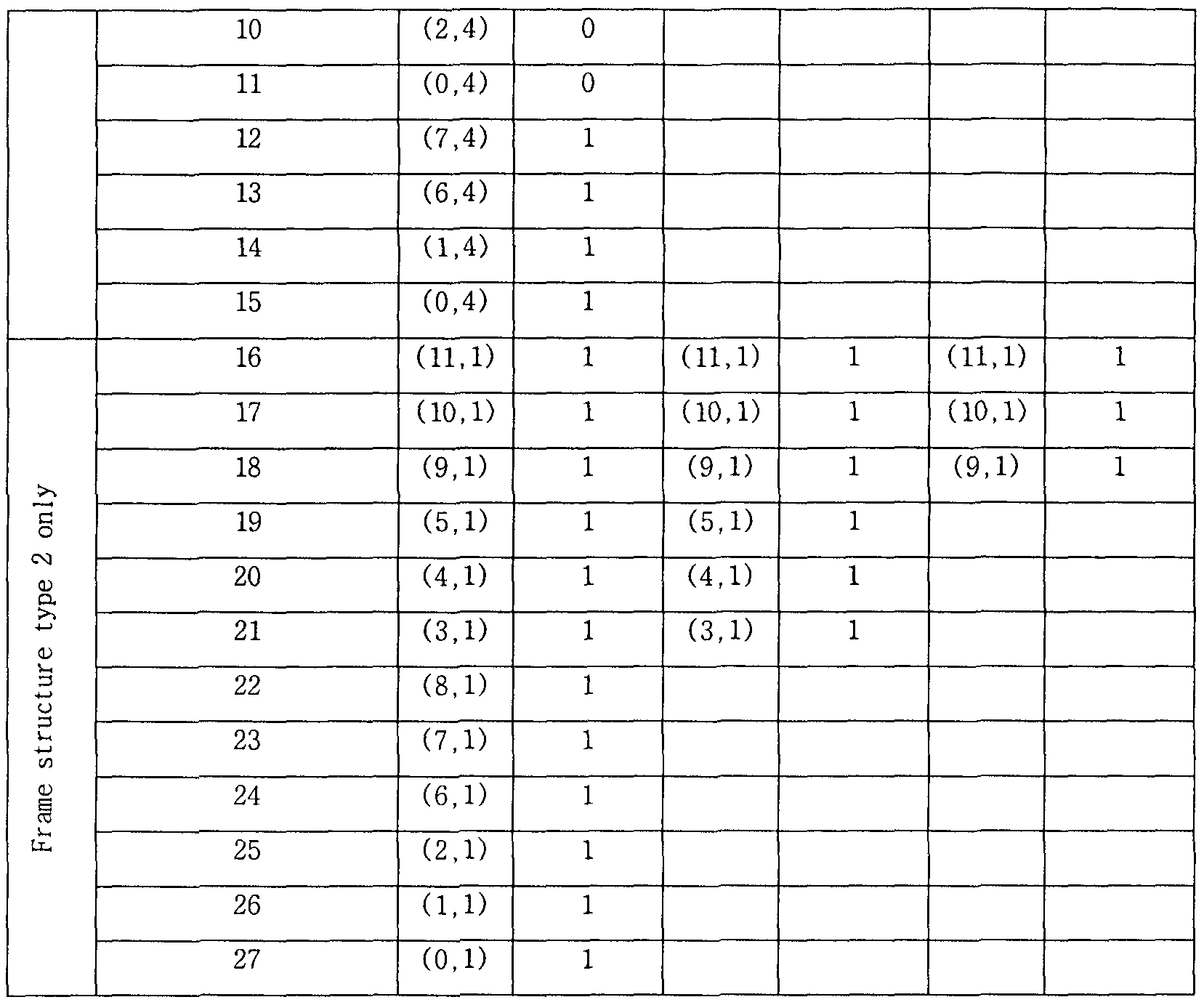


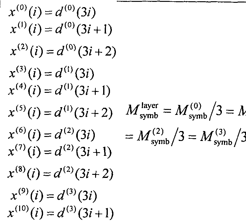
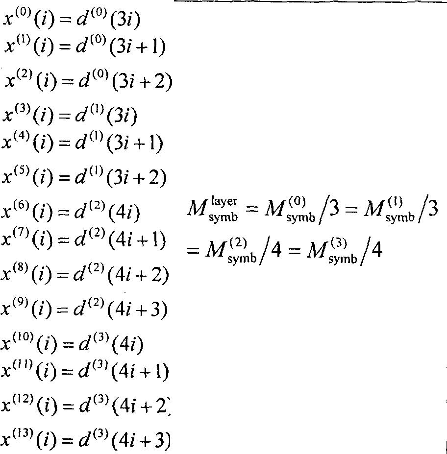


Claims
Priority Applications (5)
| Application Number | Priority Date | Filing Date | Title |
|---|---|---|---|
| CN201480009616.3A CN105075321B (en) | 2013-01-14 | 2014-01-14 | The method and user equipment of channel state information are sent in a wireless communication system |
| KR1020157021314A KR20150135217A (en) | 2013-01-14 | 2014-01-14 | Method for reporting channel state information for three-dimensional beamforming in wireless communication system and device therefor |
| US14/760,439 US9985709B2 (en) | 2013-01-14 | 2014-01-14 | Method for reporting channel state information for three-dimensional beamforming in wireless communication system and device therefor |
| JP2015552587A JP6306052B2 (en) | 2013-01-14 | 2014-01-14 | Method and apparatus for reporting channel state information for 3-dimensional beamforming in a wireless communication system |
| EP14738065.3A EP2945414B1 (en) | 2013-01-14 | 2014-01-14 | Method for reporting channel state information for three-dimensional beamforming in wireless communication system and device therefor |
Applications Claiming Priority (4)
| Application Number | Priority Date | Filing Date | Title |
|---|---|---|---|
| US201361752420P | 2013-01-14 | 2013-01-14 | |
| US61/752,420 | 2013-01-14 | ||
| US201361766670P | 2013-02-19 | 2013-02-19 | |
| US61/766,670 | 2013-02-19 |
Publications (1)
| Publication Number | Publication Date |
|---|---|
| WO2014109622A1 true WO2014109622A1 (en) | 2014-07-17 |
Family
ID=51167198
Family Applications (1)
| Application Number | Title | Priority Date | Filing Date |
|---|---|---|---|
| PCT/KR2014/000388 WO2014109622A1 (en) | 2013-01-14 | 2014-01-14 | Method for reporting channel state information for three-dimensional beamforming in wireless communication system and device therefor |
Country Status (6)
| Country | Link |
|---|---|
| US (1) | US9985709B2 (en) |
| EP (1) | EP2945414B1 (en) |
| JP (1) | JP6306052B2 (en) |
| KR (1) | KR20150135217A (en) |
| CN (1) | CN105075321B (en) |
| WO (1) | WO2014109622A1 (en) |
Cited By (8)
| Publication number | Priority date | Publication date | Assignee | Title |
|---|---|---|---|---|
| CN104243008A (en) * | 2014-09-29 | 2014-12-24 | 中国联合网络通信集团有限公司 | Limited information feedback method and device |
| CN106033987A (en) * | 2015-03-20 | 2016-10-19 | 上海贝尔股份有限公司 | Method and device for increasing sounding reference signal capacity |
| CN106160821A (en) * | 2015-03-31 | 2016-11-23 | 电信科学技术研究院 | A kind of information feedback, acquisition methods and device |
| CN106664192A (en) * | 2015-01-30 | 2017-05-10 | 韩国电子通信研究院 | Method and apparatus for transmitting downlink reference signal, and method and apparatus for transmitting control information in multi-cell collaborative communication system |
| WO2018019123A1 (en) * | 2016-07-25 | 2018-02-01 | 上海朗帛通信技术有限公司 | Method and apparatus for wireless transmission |
| JP2018507607A (en) * | 2015-01-19 | 2018-03-15 | クゥアルコム・インコーポレイテッドQualcomm Incorporated | Extended CSI feedback for FD-MIMO |
| WO2019047090A1 (en) * | 2017-09-07 | 2019-03-14 | 南通朗恒通信技术有限公司 | Method and apparatus for wireless communication in user device and base station |
| US11121752B2 (en) | 2016-01-07 | 2021-09-14 | Qualcomm Incorporated | Enhanced CSI feedback for FD-MIMO |
Families Citing this family (34)
| Publication number | Priority date | Publication date | Assignee | Title |
|---|---|---|---|---|
| CN103974315B (en) * | 2013-02-05 | 2018-01-19 | 电信科学技术研究院 | Three dimensional channel measures resource distribution and mass measuring method and equipment |
| CN105191164B (en) * | 2013-04-02 | 2020-06-09 | 太阳专利托管公司 | Method for mapping CSI-RS port to antenna unit and base station |
| KR102285852B1 (en) | 2013-12-17 | 2021-08-05 | 삼성전자 주식회사 | Method and apparatus for communication in full dimension mimo mobile communication system |
| US9667328B2 (en) * | 2014-03-31 | 2017-05-30 | Samsung Electronics Co., Ltd. | Precoding matrix codebook design and periodic channel state information feedback for advanced wireless communication systems |
| CN107078773B (en) * | 2014-09-25 | 2020-11-17 | 瑞典爱立信有限公司 | Network node, user equipment and method thereof for enabling UE to determine precoder codebook |
| US11223394B2 (en) * | 2014-11-14 | 2022-01-11 | Interdigital Patent Holdings, Inc. | Antenna virtualization in two-dimensional antenna array |
| CN105991483B (en) * | 2015-01-28 | 2020-08-07 | 索尼公司 | Wireless communication apparatus and wireless communication method |
| WO2017034509A1 (en) | 2015-08-26 | 2017-03-02 | Intel IP Corporation | Managing aspects of receive beamforming |
| WO2017075839A1 (en) * | 2015-11-06 | 2017-05-11 | 华为技术有限公司 | Method and device for measuring and feeding back channel state information (csi) |
| CN106850123B (en) * | 2015-11-30 | 2020-02-21 | 上海诺基亚贝尔股份有限公司 | Method and apparatus for layer mapping and de-layer mapping in a wireless communication system |
| WO2017096558A1 (en) * | 2015-12-09 | 2017-06-15 | Qualcomm Incorporated | Flexible resource mapping and mcs determination |
| WO2017193331A1 (en) * | 2016-05-12 | 2017-11-16 | Qualcomm Incorporated | Hybrid class b fd-mimo |
| WO2017194019A1 (en) * | 2016-05-13 | 2017-11-16 | 中兴通讯股份有限公司 | Method, device, and system for transmitting signaling |
| CN107370591B (en) * | 2016-05-13 | 2022-03-01 | 中兴通讯股份有限公司 | Signaling transmission method, device and system |
| CA3038706A1 (en) | 2016-09-30 | 2018-04-05 | Guangdong Oppo Mobile Telecommunications Corp., Ltd. | Method for managing wave beam, terminal device and network device |
| EP3905564B1 (en) * | 2016-11-02 | 2023-01-18 | Apple Inc. | Mimo (multiple input multiple output) layer transmission for nr (new radio) |
| CN108270470B (en) * | 2016-12-30 | 2021-02-23 | 华为技术有限公司 | Data transmission method, sending end equipment and receiving end equipment |
| CN108282321B (en) * | 2017-01-06 | 2022-03-29 | 华为技术有限公司 | Information indication method, network equipment and terminal equipment |
| CN115664476A (en) | 2017-02-06 | 2023-01-31 | 中兴通讯股份有限公司 | Channel information feedback and receiving method and device |
| CN108923896B (en) | 2017-04-19 | 2021-03-26 | 上海朗帛通信技术有限公司 | Method and device used in paging user equipment and base station |
| US10536205B2 (en) * | 2017-04-26 | 2020-01-14 | Samsung Electronics Co., Ltd. | Method and apparatus to CSI reporting using multiple antenna panels in advanced wireless communication systems |
| US10396871B2 (en) | 2017-06-15 | 2019-08-27 | At&T Intellectual Property I, L.P. | Layer mapping subset restriction for 5G wireless communication systems |
| MX2019015112A (en) | 2017-06-16 | 2020-02-05 | Ericsson Telefon Ab L M | Channel state information for reference signals in a wireless communication system. |
| US11139878B2 (en) | 2017-09-08 | 2021-10-05 | Apple Inc. | Group based beam reporting and channel state information reference signal configuration in new radio systems |
| ES2910991T3 (en) * | 2017-09-30 | 2022-05-17 | Guangdong Oppo Mobile Telecommunications Corp Ltd | Method for calculating channel quality indicator (CQI), terminal device and network device |
| CN109660284A (en) * | 2017-10-11 | 2019-04-19 | 索尼公司 | Electronic equipment, communication means and storage medium in wireless communication system |
| US11258566B2 (en) * | 2017-10-18 | 2022-02-22 | Qualcomm Incorporated | Aperiodic tracking reference signal |
| CN111566975B (en) * | 2018-02-14 | 2022-05-24 | 中兴通讯股份有限公司 | Method and apparatus for configuration of reference signals |
| EP3761736A4 (en) * | 2018-02-28 | 2021-11-24 | Ntt Docomo, Inc. | User equipment and wireless communication method |
| CN111726148B (en) | 2019-03-21 | 2022-10-18 | 三星电子株式会社 | Wireless communication device for adaptive beamforming and method of operating the same |
| CN110493831B (en) * | 2019-07-30 | 2021-09-28 | 维沃移动通信有限公司 | Power determination method and terminal equipment |
| EP4005103A1 (en) * | 2019-08-01 | 2022-06-01 | Huawei Technologies Co., Ltd. | Adaptive kronecker product mimo precoding for a multi-antenna network entity and a wireless communication device and corresponding methods |
| US10973062B2 (en) | 2019-08-26 | 2021-04-06 | International Business Machines Corporation | Method for extracting environment information leveraging directional communication |
| IL292217A (en) * | 2022-04-13 | 2023-11-01 | Qualcomm Inc | Two-step user equipment assisted code block mapping adaptation |
Citations (5)
| Publication number | Priority date | Publication date | Assignee | Title |
|---|---|---|---|---|
| KR20090093388A (en) * | 2008-02-29 | 2009-09-02 | 한국과학기술원 | Method and apparatus for random beamforming in multiple-input multiple-output wireless communication system |
| US20100027697A1 (en) * | 2006-11-06 | 2010-02-04 | Qualcomm Incorporated | Mimo transmission with layer permutation in a wireless communication system |
| KR20100096016A (en) * | 2009-02-22 | 2010-09-01 | 엘지전자 주식회사 | A method for generating downlink in downlink mimo system |
| KR20100099650A (en) * | 2009-03-03 | 2010-09-13 | 엘지전자 주식회사 | Method for transmitting uplink signal in mimo wireless communication system |
| WO2011138979A1 (en) * | 2010-05-03 | 2011-11-10 | Pantech Co., Ltd. | Method for feedback and receive channel information method, receiver and transmitter thereof in wireless communication system |
Family Cites Families (8)
| Publication number | Priority date | Publication date | Assignee | Title |
|---|---|---|---|---|
| EP1545082A3 (en) * | 2003-12-17 | 2005-08-03 | Kabushiki Kaisha Toshiba | Signal decoding methods and apparatus |
| JP2011527137A (en) * | 2008-07-03 | 2011-10-20 | テレフオンアクチーボラゲット エル エム エリクソン(パブル) | Method and configuration in a wireless communication system |
| KR101611272B1 (en) * | 2008-11-07 | 2016-04-11 | 엘지전자 주식회사 | Method for transmitting a reference signal |
| US8432873B2 (en) | 2009-01-12 | 2013-04-30 | Qualcomm Incorporated | Method and apparatus for computing and reporting channel quality indication (CQI) |
| WO2011087272A2 (en) * | 2010-01-18 | 2011-07-21 | Lg Electronics Inc. | A method and an apparatus for providing channel quality information in a wireless communication system |
| CN101800628B (en) | 2010-02-12 | 2015-09-16 | 中兴通讯股份有限公司 | A kind of method and system obtaining channel condition information |
| CN101834707B (en) * | 2010-04-04 | 2016-03-30 | 中兴通讯股份有限公司 | A kind of obtain channel condition information method and corresponding communication system |
| CN101958773B (en) | 2010-09-30 | 2016-08-24 | 中兴通讯股份有限公司 | The method of feedback channel information and terminal |
-
2014
- 2014-01-14 CN CN201480009616.3A patent/CN105075321B/en not_active Expired - Fee Related
- 2014-01-14 JP JP2015552587A patent/JP6306052B2/en not_active Expired - Fee Related
- 2014-01-14 US US14/760,439 patent/US9985709B2/en not_active Expired - Fee Related
- 2014-01-14 WO PCT/KR2014/000388 patent/WO2014109622A1/en active Application Filing
- 2014-01-14 EP EP14738065.3A patent/EP2945414B1/en not_active Not-in-force
- 2014-01-14 KR KR1020157021314A patent/KR20150135217A/en not_active Application Discontinuation
Patent Citations (5)
| Publication number | Priority date | Publication date | Assignee | Title |
|---|---|---|---|---|
| US20100027697A1 (en) * | 2006-11-06 | 2010-02-04 | Qualcomm Incorporated | Mimo transmission with layer permutation in a wireless communication system |
| KR20090093388A (en) * | 2008-02-29 | 2009-09-02 | 한국과학기술원 | Method and apparatus for random beamforming in multiple-input multiple-output wireless communication system |
| KR20100096016A (en) * | 2009-02-22 | 2010-09-01 | 엘지전자 주식회사 | A method for generating downlink in downlink mimo system |
| KR20100099650A (en) * | 2009-03-03 | 2010-09-13 | 엘지전자 주식회사 | Method for transmitting uplink signal in mimo wireless communication system |
| WO2011138979A1 (en) * | 2010-05-03 | 2011-11-10 | Pantech Co., Ltd. | Method for feedback and receive channel information method, receiver and transmitter thereof in wireless communication system |
Non-Patent Citations (1)
| Title |
|---|
| See also references of EP2945414A4 * |
Cited By (14)
| Publication number | Priority date | Publication date | Assignee | Title |
|---|---|---|---|---|
| CN104243008B (en) * | 2014-09-29 | 2018-03-06 | 中国联合网络通信集团有限公司 | A kind of method and apparatus of Limited Feedback information |
| CN104243008A (en) * | 2014-09-29 | 2014-12-24 | 中国联合网络通信集团有限公司 | Limited information feedback method and device |
| US10826577B2 (en) | 2015-01-19 | 2020-11-03 | Qualcomm Incorporated | Enhanced CSI feedback for FD-MIMO |
| JP2018507607A (en) * | 2015-01-19 | 2018-03-15 | クゥアルコム・インコーポレイテッドQualcomm Incorporated | Extended CSI feedback for FD-MIMO |
| US11611378B2 (en) | 2015-01-19 | 2023-03-21 | Qualcomm Incorporated | Enhanced CSI feedback for FD-MIMO |
| CN106664192A (en) * | 2015-01-30 | 2017-05-10 | 韩国电子通信研究院 | Method and apparatus for transmitting downlink reference signal, and method and apparatus for transmitting control information in multi-cell collaborative communication system |
| CN106033987A (en) * | 2015-03-20 | 2016-10-19 | 上海贝尔股份有限公司 | Method and device for increasing sounding reference signal capacity |
| CN106160821A (en) * | 2015-03-31 | 2016-11-23 | 电信科学技术研究院 | A kind of information feedback, acquisition methods and device |
| US10305569B2 (en) | 2015-03-31 | 2019-05-28 | China Academy Of Telecommunications Technology | Channel state information feedback and acquisition method and device |
| US11121752B2 (en) | 2016-01-07 | 2021-09-14 | Qualcomm Incorporated | Enhanced CSI feedback for FD-MIMO |
| WO2018019123A1 (en) * | 2016-07-25 | 2018-02-01 | 上海朗帛通信技术有限公司 | Method and apparatus for wireless transmission |
| US11019634B2 (en) | 2016-07-25 | 2021-05-25 | Shanghai Langbo Communication Technology Company Limited | Method and device in wireless transmission |
| US11950272B2 (en) | 2016-07-25 | 2024-04-02 | Shanghai Langbo Communication Technology Company Limited | Method and device in wireless transmission |
| WO2019047090A1 (en) * | 2017-09-07 | 2019-03-14 | 南通朗恒通信技术有限公司 | Method and apparatus for wireless communication in user device and base station |
Also Published As
| Publication number | Publication date |
|---|---|
| CN105075321A (en) | 2015-11-18 |
| US9985709B2 (en) | 2018-05-29 |
| JP2016511953A (en) | 2016-04-21 |
| EP2945414B1 (en) | 2018-03-07 |
| KR20150135217A (en) | 2015-12-02 |
| JP6306052B2 (en) | 2018-04-04 |
| CN105075321B (en) | 2018-11-09 |
| US20150358060A1 (en) | 2015-12-10 |
| EP2945414A1 (en) | 2015-11-18 |
| EP2945414A4 (en) | 2016-08-10 |
Similar Documents
| Publication | Publication Date | Title |
|---|---|---|
| JP6306052B2 (en) | Method and apparatus for reporting channel state information for 3-dimensional beamforming in a wireless communication system | |
| US10461906B2 (en) | Method for setting reference signal in multi-cell based wireless communication system and apparatus therefor | |
| KR102110494B1 (en) | Method and apparatus for performing cooperative transmission in wireless communication system | |
| US9825682B2 (en) | Method for reporting channel state information for three-dimensional beam forming in wireless communication system and apparatus therefor | |
| KR101668709B1 (en) | Method for reporting channel state information for 3-dimensional beam forming in wireless communications system | |
| US20150304997A1 (en) | Method for transmitting and receiving signal in multiple cell-based wireless communication system, and apparatus for same | |
| WO2014042378A2 (en) | Method for receiving signal using interference removal scheme and apparatus for same in wireless communication system | |
| WO2015016487A1 (en) | Method for performing antenna shuffling using partial antenna array based beamforming in wireless communication system, and apparatus therefor | |
| WO2015016489A1 (en) | Method for reporting channel state information for partial antenna array based beamforming in wireless communication system, and apparatus therefor | |
| EP3143704A1 (en) | Method and apparatus for calculating feedback information for 3d mimo in wireless communication system | |
| EP3100366A1 (en) | Feedback reporting method for massive antenna array based beamforming in wireless communication system, and apparatus therefor | |
| WO2014021565A1 (en) | Method for reporting aperiodic channel status information in multi cell-based wireless communication system and device therefor | |
| WO2014185645A1 (en) | Method for configuring reference signal for multi-antenna-based beamforming in wireless communication system and device for same | |
| WO2016111427A1 (en) | Method for configuring channel state information using polarization characteristics of antenna in wireless communication system and device therefor | |
| WO2014123317A1 (en) | Method for measuring channel and interference in wireless communication system | |
| EP3110049A1 (en) | Method by which terminal reports channel status information in wireless communication system, and apparatus therefor | |
| US10686503B2 (en) | Method and apparatus for reporting channel quality information for 3D MIMO in wireless communication system | |
| WO2016111521A1 (en) | Method for reporting channel quality information in tdd type wireless communication system, and device therefor | |
| WO2016153112A1 (en) | Method for generating channel state information for three-dimensional mimo in wireless communication system, and device therefor | |
| WO2018084405A1 (en) | Method for configuring reference signal for open-loop multi-antenna transmission in wireless communication system and apparatus therefor | |
| WO2012141384A1 (en) | Method for suppressing interference of terminal in multiple input multiple output wireless communication system and apparatus therefor |
Legal Events
| Date | Code | Title | Description |
|---|---|---|---|
| WWE | Wipo information: entry into national phase |
Ref document number: 201480009616.3 Country of ref document: CN |
|
| 121 | Ep: the epo has been informed by wipo that ep was designated in this application |
Ref document number: 14738065 Country of ref document: EP Kind code of ref document: A1 |
|
| WWE | Wipo information: entry into national phase |
Ref document number: 14760439 Country of ref document: US |
|
| ENP | Entry into the national phase |
Ref document number: 2015552587 Country of ref document: JP Kind code of ref document: A |
|
| NENP | Non-entry into the national phase |
Ref country code: DE |
|
| WWE | Wipo information: entry into national phase |
Ref document number: 2014738065 Country of ref document: EP |
|
| ENP | Entry into the national phase |
Ref document number: 20157021314 Country of ref document: KR Kind code of ref document: A |