WO2014109363A1 - マグネシウム精錬装置およびマグネシウム精錬方法 - Google Patents
マグネシウム精錬装置およびマグネシウム精錬方法 Download PDFInfo
- Publication number
- WO2014109363A1 WO2014109363A1 PCT/JP2014/050236 JP2014050236W WO2014109363A1 WO 2014109363 A1 WO2014109363 A1 WO 2014109363A1 JP 2014050236 W JP2014050236 W JP 2014050236W WO 2014109363 A1 WO2014109363 A1 WO 2014109363A1
- Authority
- WO
- WIPO (PCT)
- Prior art keywords
- magnesium
- sample
- reaction
- briquette
- container
- Prior art date
- Legal status (The legal status is an assumption and is not a legal conclusion. Google has not performed a legal analysis and makes no representation as to the accuracy of the status listed.)
- Ceased
Links
Images




Classifications
-
- C—CHEMISTRY; METALLURGY
- C22—METALLURGY; FERROUS OR NON-FERROUS ALLOYS; TREATMENT OF ALLOYS OR NON-FERROUS METALS
- C22B—PRODUCTION AND REFINING OF METALS; PRETREATMENT OF RAW MATERIALS
- C22B9/00—General processes of refining or remelting of metals; Apparatus for electroslag or arc remelting of metals
- C22B9/02—Refining by liquating, filtering, centrifuging, distilling, or supersonic wave action including acoustic waves
-
- C—CHEMISTRY; METALLURGY
- C22—METALLURGY; FERROUS OR NON-FERROUS ALLOYS; TREATMENT OF ALLOYS OR NON-FERROUS METALS
- C22B—PRODUCTION AND REFINING OF METALS; PRETREATMENT OF RAW MATERIALS
- C22B26/00—Obtaining alkali, alkaline earth metals or magnesium
- C22B26/20—Obtaining alkaline earth metals or magnesium
- C22B26/22—Obtaining magnesium
-
- F—MECHANICAL ENGINEERING; LIGHTING; HEATING; WEAPONS; BLASTING
- F24—HEATING; RANGES; VENTILATING
- F24S—SOLAR HEAT COLLECTORS; SOLAR HEAT SYSTEMS
- F24S20/00—Solar heat collectors specially adapted for particular uses or environments
- F24S20/30—Solar heat collectors for heating objects, e.g. solar cookers or solar furnaces
-
- F—MECHANICAL ENGINEERING; LIGHTING; HEATING; WEAPONS; BLASTING
- F24—HEATING; RANGES; VENTILATING
- F24S—SOLAR HEAT COLLECTORS; SOLAR HEAT SYSTEMS
- F24S50/00—Arrangements for controlling solar heat collectors
- F24S50/20—Arrangements for controlling solar heat collectors for tracking
-
- F—MECHANICAL ENGINEERING; LIGHTING; HEATING; WEAPONS; BLASTING
- F27—FURNACES; KILNS; OVENS; RETORTS
- F27B—FURNACES, KILNS, OVENS OR RETORTS IN GENERAL; OPEN SINTERING OR LIKE APPARATUS
- F27B17/00—Furnaces of a kind not covered by any of groups F27B1/00 - F27B15/00
-
- F—MECHANICAL ENGINEERING; LIGHTING; HEATING; WEAPONS; BLASTING
- F27—FURNACES; KILNS; OVENS; RETORTS
- F27B—FURNACES, KILNS, OVENS OR RETORTS IN GENERAL; OPEN SINTERING OR LIKE APPARATUS
- F27B5/00—Muffle furnaces; Retort furnaces; Other furnaces in which the charge is held completely isolated
- F27B5/06—Details, accessories or equipment specially adapted for furnaces of these types
- F27B5/14—Arrangements of heating devices
-
- F—MECHANICAL ENGINEERING; LIGHTING; HEATING; WEAPONS; BLASTING
- F27—FURNACES; KILNS; OVENS; RETORTS
- F27B—FURNACES, KILNS, OVENS OR RETORTS IN GENERAL; OPEN SINTERING OR LIKE APPARATUS
- F27B5/00—Muffle furnaces; Retort furnaces; Other furnaces in which the charge is held completely isolated
- F27B5/06—Details, accessories or equipment specially adapted for furnaces of these types
- F27B5/18—Arrangement of controlling, monitoring, alarm or like devices
-
- F—MECHANICAL ENGINEERING; LIGHTING; HEATING; WEAPONS; BLASTING
- F27—FURNACES; KILNS; OVENS; RETORTS
- F27D—DETAILS OR ACCESSORIES OF FURNACES, KILNS, OVENS OR RETORTS, IN SO FAR AS THEY ARE OF KINDS OCCURRING IN MORE THAN ONE KIND OF FURNACE
- F27D99/00—Subject matter not provided for in other groups of this subclass
- F27D99/0001—Heating elements or systems
-
- Y—GENERAL TAGGING OF NEW TECHNOLOGICAL DEVELOPMENTS; GENERAL TAGGING OF CROSS-SECTIONAL TECHNOLOGIES SPANNING OVER SEVERAL SECTIONS OF THE IPC; TECHNICAL SUBJECTS COVERED BY FORMER USPC CROSS-REFERENCE ART COLLECTIONS [XRACs] AND DIGESTS
- Y02—TECHNOLOGIES OR APPLICATIONS FOR MITIGATION OR ADAPTATION AGAINST CLIMATE CHANGE
- Y02B—CLIMATE CHANGE MITIGATION TECHNOLOGIES RELATED TO BUILDINGS, e.g. HOUSING, HOUSE APPLIANCES OR RELATED END-USER APPLICATIONS
- Y02B10/00—Integration of renewable energy sources in buildings
- Y02B10/20—Solar thermal
-
- Y—GENERAL TAGGING OF NEW TECHNOLOGICAL DEVELOPMENTS; GENERAL TAGGING OF CROSS-SECTIONAL TECHNOLOGIES SPANNING OVER SEVERAL SECTIONS OF THE IPC; TECHNICAL SUBJECTS COVERED BY FORMER USPC CROSS-REFERENCE ART COLLECTIONS [XRACs] AND DIGESTS
- Y02—TECHNOLOGIES OR APPLICATIONS FOR MITIGATION OR ADAPTATION AGAINST CLIMATE CHANGE
- Y02E—REDUCTION OF GREENHOUSE GAS [GHG] EMISSIONS, RELATED TO ENERGY GENERATION, TRANSMISSION OR DISTRIBUTION
- Y02E10/00—Energy generation through renewable energy sources
- Y02E10/40—Solar thermal energy, e.g. solar towers
- Y02E10/47—Mountings or tracking
-
- Y—GENERAL TAGGING OF NEW TECHNOLOGICAL DEVELOPMENTS; GENERAL TAGGING OF CROSS-SECTIONAL TECHNOLOGIES SPANNING OVER SEVERAL SECTIONS OF THE IPC; TECHNICAL SUBJECTS COVERED BY FORMER USPC CROSS-REFERENCE ART COLLECTIONS [XRACs] AND DIGESTS
- Y02—TECHNOLOGIES OR APPLICATIONS FOR MITIGATION OR ADAPTATION AGAINST CLIMATE CHANGE
- Y02P—CLIMATE CHANGE MITIGATION TECHNOLOGIES IN THE PRODUCTION OR PROCESSING OF GOODS
- Y02P10/00—Technologies related to metal processing
- Y02P10/20—Recycling
Definitions
- the present invention relates to a magnesium refining apparatus and a magnesium refining method.
- Patent Document 1 a technique for reducing metal oxides using solar energy, which is natural energy, is known (for example, Patent Document 1).
- the magnesium refining apparatus includes a storage container that stores a sample containing a magnesium compound, and condenses sunlight to irradiate the storage container so that the interior of the storage container reaches a predetermined temperature. And a condenser that heats the container to a predetermined temperature by the condensing device to generate magnesium vapor from the sample by a thermal reduction reaction, and a condenser that condenses the magnesium vapor.
- a sunlight transmitting member that transmits sunlight collected by the light collecting device is provided on the surface of the housing of the storage container, and the reaction unit is held inside the storage container. A sample is carried into the interior of the container.
- the containing container has a shield part for preventing magnesium vapor generated by the thermal reduction reaction from adhering to the solar light transmitting member.
- the surface of the shield part is provided with a passing region through which sunlight condensed by the light collecting device and transmitted through the sunlight transmitting member is passed, and the reaction part is held inside the shield part. Is preferred.
- the shield portion is formed by coating the reflective material except for the passage region on the inner surface or the outer surface of the casing made of the transparent material.
- the reaction part and the condenser part are integrally formed and held inside the storage container, and the longitudinal direction of the storage container One end of the container is held at a lower altitude than the other end, and inside the condenser part, liquid magnesium condensed from magnesium vapor extends in the longitudinal direction toward the one end of the container. It is preferable to provide a guide member that guides the air flow.
- the recovery unit that is provided below one end of the storage container and recovers the liquid magnesium condensed in the condenser part in a liquid state. Furthermore, it is preferable that the recovery unit recovers the liquid magnesium dropped from the condenser unit by the action of gravity.
- a carry-in port for carrying the sample into the storage container a carry-out port for carrying out the sample from the storage container, And a transport unit that transports the sample along a transport path connecting from the transport inlet to the transport outlet.
- the transport path passes through the inside of the reaction unit to heat the sample. It is preferably constituted by a reaction conveyance path for causing the reduction reaction.
- the transport path is opposite to the first partial transport path in which the sample is transported from the transport inlet in the first transport direction, and to the first transport direction.
- the sample is cylindrical, the central axis of the sample coincides with the sample transport direction, and the transport unit is at least the reaction unit.
- the apparatus in the magnesium refining apparatus according to the seventh or eighth aspect, the sample is prismatic, and the transport unit moves the sample two-dimensionally on a predetermined plane at least in the opposite part. It is preferable.
- the apparatus in the magnesium refining device according to any one of the seventh to tenth aspects, the apparatus further includes a determination unit that determines whether or not the sample is usable, and the transport unit includes When it is determined that the sample is not usable, it is preferable to carry out the sample from the storage container via the carry-out port.
- the determination unit is not usable when the number of times that the sample has passed through the reaction transport path exceeds a predetermined number. Is preferably determined.
- the sample containing the magnesium compound is stored in the storage container, the sunlight is collected and irradiated to the storage container, and the interior of the storage container reaches a predetermined temperature.
- magnesium vapor is generated from the sample by a thermal reduction reaction inside the reaction part provided in the container, and the magnesium vapor is condensed inside the condenser part provided in the container.
- the reaction part and the condenser part are integrally formed and held inside the container, and one end of the container in the longitudinal direction is provided. Is held at a lower altitude than the other end, and inside the condenser part, the liquid magnesium condensed from the magnesium vapor is guided to flow in the longitudinal direction toward the one end of the container. It is preferable.
- the inlet for carrying the sample into the storage container and the outlet for discharging the sample from the storage container are connected, and at least It is preferable to transport the sample along a transport path that partially passes through the inside of the reaction section.
- a sample having a cylindrical shape whose central axis coincides with the transport direction is rotated around the axis of the cylinder at least in the reaction section. However, it is preferable to carry it.
- the prismatic sample is moved two-dimensionally on a predetermined plane at least in the reaction part.
- the sample in the container can be heated at a predetermined temperature required for the thermal reduction reaction by collecting sunlight with the light collecting device and irradiating the container.
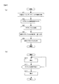
- FIG. 9A is a flowchart for explaining a magnesium refining method using a magnesium refining apparatus
- FIG. 9B is a flowchart for explaining a conveying process of a feeder.
- the Pigeon method is known as an example of the refining method of magnesium.
- briquettes are produced by mixing dolomite ore (CaMg (CO 3 ) 2 ) into an oxide and ferrosilicon.
- the produced briquette is accommodated in a reaction furnace (retort), and magnesium vapor is generated by a thermal reduction reaction by heating at a high temperature of about 1200 ° C. for about 8 hours under vacuum.
- This magnesium vapor is condensed to take out magnesium as crystals. Since high-purity magnesium is easy to burn and is dangerous to transport, it has been made flame retardant as a magnesium alloy by adding another element. That is, in order to produce a magnesium alloy, a desired material is obtained by adding necessary substances and heating again.
- the first embodiment of the present invention relates to a magnesium refining apparatus that prevents the generation of carbon dioxide as described above, has high durability against high-temperature and long-time heating, and has a low environmental load.
- the magnesium refining apparatus of the present embodiment uses the energy of sunlight condensed by a solar furnace to heat a sample (briquette) at a predetermined temperature and refines magnesium by a thermal reduction reaction. At that time, magnesium refined by the thermal reduction reaction contains a predetermined amount of calcium, so that magnesium having flame retardancy is generated. In this case, heating is performed to a temperature at which the vapor pressure of calcium is a predetermined percentage with respect to the vapor pressure of magnesium during the thermal reduction reaction. That is, flame retardant magnesium containing calcium is obtained by using a conventional pigeon method to increase the magnesium generation temperature by the thermal reduction reaction to a higher temperature. Details will be described below.
- FIG. 1 is a diagram showing an example of the configuration of the magnesium refining apparatus 1.
- the magnesium refining device 1 includes a light collecting unit 10, a retort 20, and a control unit 30.
- the light collecting unit 10 according to the present embodiment includes a primary mirror 101, a direct light sensor 104, and a drive mechanism 105.
- the primary mirror 101 is configured to have a parabolic surface (parabolic surface) by combining, for example, a plurality of concave mirrors and plane mirrors.
- a parabolic surface parbolic surface
- the primary mirror 101 has a light collection degree of 2000 times or more, and focuses on a position where the sample in the retort 20 is carried. Composed.
- the energy of sunlight heats the sample in the retort 20 by the primary mirror 101 of the light collecting unit 10.
- the primary mirror 101 is driven in the horizontal direction and / or the elevation direction according to the movement of the sun using a known technique, and performs the tracking drive so as to face the sun.
- the control unit 30 calculates the solar position calculated based on the time and the installation position of the light collecting unit 10 (for example, latitude and longitude information) and the amount of solar radiation directly received from the direct light sensor 104.
- the driving amount for the primary mirror 101 to face the sun is calculated according to the signal (direct solar radiation amount signal) according to the above.
- the drive mechanism 105 inputs a drive signal indicating the drive amount calculated by the control unit 30 and drives the primary mirror 101 in the horizontal direction and / or the elevation direction.
- the retort 20 is configured to be detachable from the primary mirror 101 and functions as a storage container for storing the briquette B (sample) therein, and the briquette B is heated by sunlight energy, so that magnesium can be thermally reduced. It functions as a reactor for precipitating.
- FIG. 2 schematically shows the structure of the retort 20.
- the retort 20 is a hollow cylindrical member formed of a material having high heat resistance.
- the retort 20 is connected to a vacuum pump or the like (not shown) and can maintain the inside in a vacuum.
- the briquette B contains at least MgO and CaO.
- the retort 20 is irradiated with condensed sunlight and reacts to generate magnesium vapor from the briquette B by a thermal reduction reaction, a condenser 22 for collecting the generated magnesium vapor, and a condenser 22 for cooling the condenser 22.
- the cooling unit 23 and a heat shield 24 that blocks heat from the reaction unit 21 are attached to the primary mirror 101 on the cooling unit 23 side.
- the briquette B is arranged inside the reaction unit 21 and is irradiated with sunlight collected by the light collecting unit 10.
- the briquette B irradiated with sunlight is locally heated to a temperature (for example, about 1400 ° C.) exceeding the boiling point of magnesium (1107 ° C.).
- the temperature at which briquette B is heated is set so that the vapor pressure of calcium is 1% to 5% with respect to the vapor pressure of magnesium.
- the condenser 22 is cooled by the cooling unit 23 so that the internal temperature is maintained at a predetermined temperature, for example, an appropriate temperature below the melting point of magnesium.
- the cooling unit 23 is a water-cooled cooling device that cools the condenser 22 by the action of cooling water using seawater or the like as an example.
- magnesium and calcium that are vaporized in the reaction unit 21 are sucked by the suction device and condensed in the condenser 22, and an alloy in which several percent of calcium is mixed into magnesium. Precipitate.
- a magnesium alloy having flame retardancy is obtained.
- magnesium hydroxide Mg obtained from dolomite mined as a raw material, as in conventional techniques (for example, Pigeon method), and bittern obtained by purifying seawater, etc. OH) 2 and a method using magnesium hydroxide Mg (OH) 2 taken out from an electrode material after use, such as a fuel cell using magnesium as an electrode material, as a raw material.
- the fired dolomite produced as described in (1) and (2) above and ferrosilicon are mixed to obtain briquette B having a predetermined size and shape.
- magnesium hydroxide (MgO) is generated by the following reaction formula (3) by adding calcium hydroxide Ca (OH) 2 and dehydrating with heating. .
- generated by (2) is mixed with magnesium oxide (MgO), and the briquette B which has a predetermined magnitude
- magnesium is generated as a vapor and is condensed in the condenser 22.
- magnesium containing a small amount of calcium condenses on the condenser 22.
- the alloy precipitated in the capacitor 22 since briquette B is heated so that the vapor pressure of calcium is 1% or more with respect to the vapor pressure of magnesium, the alloy precipitated in the capacitor 22 also has 1 calcium relative to magnesium. Add more than percent.
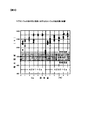
- FIG. 3 is a graph showing the relationship between the amount of calcium added and the ignition temperature of the magnesium alloy.
- the ignition temperature can be set to 1000K or higher. This is considerably higher than the ignition temperature of pure magnesium is 800K or less.
- the amount of calcium added is 1 percent or more with respect to magnesium as described above. Therefore, the magnesium alloy produced by the magnesium refining apparatus 1 exhibits flame retardancy. Thereby, the safety
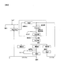
- FIG. 4 shows a system for producing a flame-retardant magnesium alloy and a recycling system as described above.
- a flame retardant magnesium alloy can be produced and used for applications such as fuel materials and electrode materials such as fuel cells.
- MgO remains.
- Ferrosilicon obtained by the reaction formula (2) is mixed with MgO to produce briquette B, which is again carried into the retort 20 of the magnesium refining apparatus 1.
- a flame-retardant magnesium alloy can be produced
- Mg (OH) 2 remains.
- MgO is produced by causing the Mg (OH) 2 to undergo the reaction shown in the reaction formula (3).
- the briquette B is generated, carried into the retort 20, and subjected to a thermal reduction reaction, whereby a flame retardant magnesium alloy can be generated again.
- the magnesium refining apparatus 1 can circulate and use magnesium.
- the sledge such as SiO 2 generated in the thermal reduction reaction of the reaction formula (4) can be used again as a reducing agent.
- the magnesium refining apparatus 1 condenses the retort 20 that contains the briquette B as a sample containing a magnesium compound, condenses sunlight and irradiates the retort 20, and heats the interior of the retort 20 to a predetermined temperature. And a light collecting unit 10 that performs the above operation.
- the retort 20 has a reaction part 21 that generates magnesium vapor from the briquette B by a thermal reduction reaction when heated to a predetermined temperature by the light collecting part 10. Therefore, magnesium can be deposited by a thermal reduction reaction using sunlight energy.
- fossil fuel is burned in a gas furnace or the like and carbon dioxide is not generated by long-time high-temperature heating, and the environment is not adversely affected.
- the retort 20 can be heated to a high temperature of 1400 ° C. Therefore, by heating to about 1400 ° C. and causing the magnesium to undergo a thermal reduction reaction, calcium can be mixed and a highly flame-retardant magnesium alloy can be obtained.
- the precipitated magnesium is heated again to obtain an alloy to which other substances are added.
- achieve the heating at high temperature of 1400 degreeC by one process by using sunlight as energy for a heating using the condensing part 10 it is flame retardance.
- the manufacturing process of magnesium can be simplified. Furthermore, since it is not necessary to obtain an alloy by reheating as in the conventional technique, the emission of carbon dioxide is suppressed and the environment is not adversely affected.
- the retort 20 further includes a condenser 22 that condenses magnesium vapor. Therefore, since a magnesium alloy can be efficiently obtained from the magnesium vapor generated by the thermal reduction reaction in the reaction part 21, a decrease in productivity can be suppressed.
- the magnesium refining apparatus according to the first embodiment can be modified as follows.
- the magnesium refining apparatus 1 can be used to generate a raw material for generating a magnesium alloy by changing the degree of condensing by the condensing unit 10 and changing the heating temperature.
- it can be used for the step of generating MgO by firing shown in the above reaction formula (3) and the step of generating ferrosilicon shown in reaction formula (2) by heating.
- the entire system that produces magnesium alloy suppresses the generation of carbon dioxide. This will not adversely affect the environment.
- the heating method of the retort 20 is not limited to the method using the light collecting unit 10 having the primary mirror 101. Sunlight is condensed and the retort 20 is irradiated and heated so that the internal temperature of the retort 20 becomes 1400 ° C., and magnesium vapor is generated from the briquette B containing the magnesium compound contained in the retort 20 by a thermal reduction reaction. Any method that can be generated can be used.
- the condensing unit 10 may use a heliostat system that condenses the reflected light reflected from each of the plurality of plane mirrors by superimposing them at one point.
- FIGS. 5 to 8 schematically show the structure of the magnesium refining apparatus 1 according to the second embodiment.
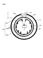
- 6 is a cross-sectional view taken along the line A1-A1 of the retort 20 shown in FIG. 5
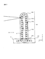
- FIG. 7 is a cross-sectional view taken along the line A2-A2 of the retort 20 shown in FIG.
- coordinate axes including an x-axis, a y-axis, and a z-axis are set as shown in FIGS.
- the condensing part 10 by 2nd Embodiment is comprised by the Cassegrain optical system which has the primary mirror 101 which consists of a concave mirror, and the secondary mirror 102 which consists of a convex mirror, and in addition to the primary mirror 101 by a paraboloid, by a hyperboloid It further has a secondary mirror 102 made of a convex mirror and a drive mechanism 102a for driving the secondary mirror 102.
- the front or back surface of the primary mirror 101 is made of a corrosion-resistant aluminum or silver film
- the secondary mirror 102 is made of, for example, a dielectric multilayer film mirror having low energy absorption.
- the condensing unit 10 In the condensing unit 10, sunlight is reflected by the primary mirror 101 and proceeds to the secondary mirror 102, and is collected by the secondary mirror 102 on the upper surface (z axis + side) of the briquette B carried into the retort 20 described later.
- the secondary mirror 102 condenses sunlight efficiently on the briquette B and arranges the retort 20 on the back surface of the primary mirror 101, so that the opening angle (NA) when the sunlight is collected on the briquette B is shown. ) Is designed to be small.
- the drive mechanism 102a drives the secondary mirror 102 by a drive signal from the control unit 30 to be described later, and changes the degree of light collection by which sunlight is collected on the surface of the briquette B.
- the retort 20 is indicated by a broken line in FIG. 5 so that one end of the longitudinal direction (x-axis direction + side) is lower than the other end (x-axis direction-side) by the control unit 30. It is supported via a posture control mechanism (not shown) in a state inclined by a predetermined angle ⁇ with respect to the horizontal plane shown. That is, the x axis is set in a direction inclined by a predetermined angle ⁇ with respect to the horizontal plane.
- the predetermined angle ⁇ is determined by an experiment or the like as an optimum angle at which magnesium that has become liquid as a result of the reduction reaction flows into and drops into the magnesium recovery unit 204 as described later.
- the retort 20 includes a window material 201, a capacitor shield 202, a second shield 203, a magnesium recovery unit 204, a feeding device 205, a temperature sensor 206, a pressure sensor 207, a pump 208, a briquette inlet 210, , A briquette exit 211 and a transport path 212 are provided.
- the window member 201 covers an opening provided in the upper part (z axis + side, the light collecting unit 10 side) of the retort 20, and transmits sunlight condensed by the light collecting unit 10 into the retort 20.
- the window material 201 reflects visible light (sunlight) such as a transparent electrode ITO film (indium tin oxide film) that reflects radiant heat from the capacitor shield 202 described later, and reflects infrared light (sunlight). A transmission infrared reflection film).
- the window material 201 is provided so as to be replaceable, and is wider than the range of the luminous flux of sunlight guided into the retort 20.
- the window member 201 is configured to be capable of two-dimensional movement on a plane parallel to the xy plane at a provided location by a drive mechanism (not shown) in accordance with a drive signal output from the control unit 30.
- the capacitor shield 202 is a hollow member provided inside the retort 20 and made of ordinary steel.
- the capacitor shield 202 is provided with an opening 202h so that sunlight from the light collecting unit 10 can be irradiated with the briquette B.
- the briquette B is conveyed on the conveyance path 212 by a feeding device 205 described later, and the briquette B is irradiated with sunlight through the opening 202h inside the capacitor shield 202.
- a communication portion 202 b that communicates with the magnesium recovery portion 204 provided below is provided at the y-axis + side end portion of the bottom portion (z-axis-side) of the capacitor shield 202.
- the diameter of the opening 202h will be described with reference to FIG. In FIG. 8, the distance in the z-axis direction between the upper surface of the briquette B (z axis + side) and the inner wall of the capacitor shield 202 is Z, and the diameter of the luminous flux of sunlight from the light converging unit 10 connected to the upper surface of the briquette B ( Let D be the spot diameter.
- the diameter H of the opening 202h is formed to satisfy the following formula (5). 2 (D + 2Ztan ⁇ 1) ⁇ H> D + 2Ztan ⁇ 1 (5)
- the inside of the capacitor shield 202 has the following configuration. As shown in FIG. 6, a plurality of guide members 202g are provided inside the capacitor shield 202 so that magnesium is guided to the magnesium recovery unit 204 via the communication unit 202b in a liquid state.
- the guide member provided along the opening end of the opening 202h is denoted by reference numeral 202g1 and provided on the bottom (z-axis-side) of the capacitor shield 202.
- the guide member is denoted by reference numeral 202g2, and the guide members other than those described above are denoted by reference numeral 202g3.
- the guide member 202g1 projects in the z-axis direction from the opening end of the opening 202h.
- the guide material 202g1 protrudes in a direction that does not block the luminous flux of sunlight incident through the window material 201. That is, the guide member 202g1 is formed so as to cover the window material 201 so that the precipitated magnesium liquid does not protrude in the direction of the window material 201.
- the guide member 202g2 is provided on the bottom inner wall of the capacitor shield 202 so as to extend along the x-axis direction.
- the guide member 202g3 protrudes from the inner wall of the capacitor shield 202 along the z-axis direction and is provided so as to extend along the x-axis direction.
- the guide members 202g1 to 202g3 are formed so that the thickness thereof is larger than the thickness of the members constituting the capacitor shield 202.
- the guide members 202g1 to 202g3 may protrude in the direction of the focal plane placed near the center of the capacitor shield 202. Further, the guide members 202g1 to 202g3 are not rectangular in cross section, and may project in a triangular shape, for example. As described above, since the surface area of the inner surface of the capacitor shield 202 is increased by having the guide members 202g1 to 202g3, a large amount of magnesium can be deposited.
- the inside of the capacitor shield 202 is maintained at a temperature exceeding the melting point of magnesium (651 ° C.), for example, about 700 ° C. to 800 ° C., and the internal pressure of the capacitor shield 202 other than magnesium vapor is adjusted to 1 Pa or less. .
- the magnesium that has become vapor due to the thermal reduction reaction reaches the inner wall of the capacitor shield 202 without being oxidized and condenses, and becomes liquid and adheres to the inner wall.
- the capacitor shield 202 is formed by integrally forming a reaction portion for causing the briquette B to undergo a thermal reduction reaction and a capacitor portion for allowing the magnesium vapor generated by the thermal reduction reaction to condense.
- the magnesium adhering to the inner wall of the capacitor shield 202 as a liquid is affected by gravity, and the guide members 202g2 and 202g3 extend. It is guided along the existing direction, i.e. the x-axis. Then, the liquid magnesium that has reached the end surface on the x-axis + side of the capacitor shield 202 flows or drops into the magnesium recovery unit 204 through the communication unit 202b.
- the second shield 203 is provided so as to hold the capacitor shield 202 inside.
- the second shield 203 is provided to prevent heat from being dissipated to the outside through the outer wall of the housing of the retort 20 due to radiant heat from the capacitor shield 202, and sunlight from the light collecting unit 10 is transmitted, but from the capacitor shield 202. It is made of a material that reflects the radiant heat.
- an inner surface of a member formed in a cylindrical shape with a transparent material such as quartz or glass is coated with aluminum. However, no coating is applied to a range 203 a in which sunlight from the light collecting unit 10 passes toward the briquette B, that is, a range corresponding to the window material 201.
- the second shield 203 mirror-finished stainless steel may be used.
- a dielectric multilayer film may be provided for the range 203a of the second shield 203 made of a transparent material such as quartz or glass, or covered with a sunlight transmitting infrared reflective film such as an ITO (indium tin oxide film) film. May be.
- a window portion made of a transparent material may be combined with the second shield 203 made of stainless steel.
- the transport path 212 includes a first transport path 212a that transports the loaded briquette B in the x-axis + direction, and a transport direction of the briquette B that is connected to the first transport path 212a and transported from the first transport path 212a.
- a second bent conveyance path 212d is provided that is connected to the second conveyance path 212c and changes the conveyance direction of the briquette B conveyed from the second conveyance path 212c to the x-axis + direction.
- a part of the second conveyance path 212c is a reaction conveyance path 212c1 that passes through the inside of the capacitor shield 202, and is provided for irradiating the briquette B with sunlight that has passed through the window member 201 to cause a thermal reduction reaction. .
- the feeding device 205 is configured by, for example, a belt, a plurality of rollers, or the like provided along the conveyance path 212.
- the feeding device 205 conveys the briquette B having a predetermined shape to the capacitor shield 202 sequentially and sequentially.
- the briquette B is formed in a cylindrical shape and is transported on the transport path 212 so that the central axis of the briquette B coincides with the transport direction.
- the feeding device 205 connects the briquette entrance 210 at the x-axis side end and the first transport path 212a in accordance with a drive signal from the control unit 30, and is carried in from the briquette entrance 210.
- Briquette B is transported in the x-axis + direction.
- the feeding device 205 connects the x-axis-side end of the first transport path 212a with the second bent transport path 212d, and the briquette B is placed on the transport path 212. Do not carry in more than necessary.
- the briquette B carried into the transport path 212 is transported in the order of the first transport path 212a, the first bent transport path 212b, the second transport path 212c, and the second bent transport path 212d, and again into the first transport path 212a. It is transported and transported on the transport path 212 in the above order.
- the briquette B moves along the x-axis-direction while rotating around the central axis of the briquette B in the x-axis direction by a rotation mechanism (not shown). .
- a rotation mechanism not shown.
- the secondary mirror 102 is finely driven by the drive mechanism 102a to move the light collection position along the optical axis direction of sunlight.
- the surface shape of the briquette B is deformed along with the thermal reduction reaction, and the distance between the upper surface (z axis + side) of the briquette B and the inner wall of the capacitor shield 202 shown in FIG. Even if the fluctuation occurs, the surface temperature of the briquette B changes at a substantially constant high temperature.
- the briquette B continues to be transported on the transport path 212 by the feeding device 205.
- the same briquette B is transported a plurality of times on the reaction transport path 212c1.
- the control unit 30 It is determined that it is not usable.
- a counter for counting the number of times the briquette B is transported through the reaction transport path 212c1, a timer for measuring time, and the like may be provided. The predetermined number of times and the predetermined time are determined in advance based on experiments and the like so that the briquette B can maintain a shape suitable for generating magnesium vapor by a thermal reduction reaction.
- the feeding device 205 separates the second transport path 212c from the second bent transport path 212d and connects it to the briquette exit 211. For this reason, the used briquette B used for the thermal reduction reaction is transported from the second transport path 212 c to the briquette exit 211 and discharged to the outside of the retort 20. By repeating the above-described operation, a predetermined amount of briquette B is transported on the transport path 212.
- the feeding device 205 controls the moving speed of the briquette B according to the speed instruction signal from the control unit 30.
- the moving speed is determined so that the briquette B is irradiated with sunlight from the light collecting unit 10 for a period sufficient to generate magnesium by the thermal reduction reaction.
- the temperature sensor 206 measures the temperature in the capacitor shield 202 and outputs a temperature signal indicating the measured temperature to the control unit 30.
- the pressure sensor 207 includes a first pressure sensor 207 a that measures the pressure inside the capacitor shield 202 and a second pressure sensor 207 b that measures the pressure inside the retort 20 outside the capacitor shield 202.
- the first pressure sensor 207a and the second pressure sensor 207b each output a pressure signal indicating the measured pressure to the control unit 30.
- the pump 208 is driven in accordance with a drive signal from the control unit 30, and the pressure inside the retort 20 inside the capacitor shield 202 and outside the capacitor shield 202 is changed to a predetermined pressure via a not-shown exhaust / exhaust system.
- the pressure inside the capacitor shield 202 measured by the first pressure sensor 207a indicates the pressure of the deposited magnesium vapor while the briquette B undergoes the thermal reduction reaction.
- the pressure in the capacitor shield 202 is adjusted to 1 Pa or less so that magnesium that has become vapor is not oxidized as described above.
- the pressure in the retort 20 outside the capacitor shield 202 is adjusted to 100 Pa or less in order to prevent transmission due to heat convection.
- the control unit 30 includes a CPU, a ROM, a RAM, and the like, and is an arithmetic device that executes various data processing.
- the control unit 30 inputs signals from various sensors such as the direct light sensor 104, the temperature sensor 206, and the pressure sensor 207 described above, and the amount of sunlight that irradiates the light collecting unit 10, the temperature in the capacitor shield 202, The pressure in the capacitor shield 202 and the retort 20 is monitored. In accordance with the monitoring result, the control unit 30 executes processing such as drive control of the light collecting unit 10, drive control of the feeding device 205, drive control of the window member 201, and the like.
- processing such as drive control of the light collecting unit 10, drive control of the feeding device 205, drive control of the window member 201, and the like.
- the control unit 30 includes a determination unit 301, a condensing unit drive control unit 302, a feeding device drive control unit 303, and a window material drive control unit 304. .
- the determination unit 301 determines whether to drive the light collecting unit 10, drive the feeding device 205, or drive the window material 201. To do. As described above, the determination unit 301 determines whether the briquette B is usable.
- the condensing unit drive control unit 302 calculates a driving amount for driving the condensing unit 10 in the horizontal direction and / or the elevation direction according to the determination result of the determining unit 301, and the driving mechanism of the condensing unit 10 as a drive signal. To 105.
- the feeding device drive control unit 303 calculates and calculates a signal for instructing the carry-in of the briquette B into or out of the retort 20 and the transport speed of the briquette B according to the determination result of the determination unit 301.
- a speed instruction signal for instructing to transport the briquette B at the transport speed is output to the feeding device 205.
- the window material drive control unit 304 outputs a drive signal instructing the drive direction and the drive amount of the window material 201 according to the determination result of the determination unit 301, so that the window material 201 is on a plane parallel to the xy plane. Drive in two dimensions. Details of processing performed by the determination unit 301, the condensing unit drive control unit 302, the feeding device drive control unit 303, and the window material drive control unit 304 will be described below.
- the determination unit 301 When the amount of solar radiation indicated by the direct solar radiation signal from the direct light sensor 104 is less than the first threshold value, the determination unit 301 has low sunlight intensity due to factors such as clouds and atmospheric conditions, and the briquette B is not heated. It determines with becoming inadequate, and determines with the time which sunlight is irradiated to Briquette B need to be lengthened. In this case, the feed device drive control unit 303 calculates a new transport speed according to the amount of solar radiation so that the transport speed of the briquette B by the feed device 205 becomes low. Then, the feed device drive control unit 303 outputs a speed instruction signal to the feed device 205 so that the briquette B is transported at the calculated transport speed.
- the briquette B can be heated to a temperature necessary for the thermal reduction reaction by increasing the irradiation time of the sunlight to the briquette B.
- the determination unit 301 determines that it is necessary to shorten the irradiation time of sunlight on the briquette B, and sends
- the device drive control unit 303 outputs a speed instruction signal to the feeding device 205 so that the transport speed of the briquette B becomes high.
- the determination unit 301 determines that the amount of magnesium vapor deposited by the thermal reduction reaction is small, and On the other hand, it is determined that a longer-time thermal reduction reaction is necessary. That is, the determination unit 301 determines that the briquette B needs to pass through the capacitor shield 202 over a longer time. Also in this case, the feed device drive control unit 303 calculates a new transport speed according to the pressure in the capacitor shield 202 so that the transport speed of the briquette B by the feed device 205 becomes low.
- the feed device drive control unit 303 outputs a speed instruction signal to the feed device 205 so that the briquette B is transported at the calculated transport speed.
- the feed device drive control unit 303 outputs a speed instruction signal to the feed device 205 so that the briquette B is transported at the calculated transport speed.
- control unit 30 outputs a drive signal to the drive mechanism 102a to finely drive the sub mirror 102 so that the temperature in the capacitor shield 202 detected by the temperature sensor 206 is maintained at 700 ° C. or higher.
- concentration of sunlight is changed, and the temperature drop in the capacitor shield 202 can be suppressed.
- the control unit 30 outputs a drive signal to the drive mechanism 102a so that the sub mirror 102 is finely controlled so that the pressure in the capacitor shield 202 measured by the first pressure sensor 207a is maintained at a predetermined pressure. Drive.
- the concentration of sunlight is changed and control can be performed so that the amount of magnesium vapor deposited from briquette B does not become insufficient, so that a decrease in productivity of the magnesium alloy can be suppressed.
- the determination unit 301 outputs a drive signal to the window material drive control unit 304 so that the window material 201 is driven in a predetermined direction by a predetermined amount every time a predetermined time has elapsed since the magnesium refining apparatus 1 is activated. Avoiding the region where the vapor of magnesium adheres to the window material 201 and the transmittance of sunlight is reduced, and directs sunlight to the surface of the briquette B through the region where the transmittance of the window material 201 is high. It is aimed.
- the predetermined direction and the predetermined amount in which the window material 201 is driven are determined in advance so that a region different from the region in which the window material 201 has faced the inside of the retort 20 so far faces the inside of the retort 20. Has been.
- the determination unit 301 keeps the pressure in the retort 20 inside the capacitor shield 202 and outside the capacitor shield 202 constant.
- a pump 208 having an exhaust speed is arranged so that the pressure value indicated by the pressure signal input from the second pressure sensor 207b does not exceed 100 Pa.
- step S1 sunlight is reflected by the primary mirror 101 and proceeds to the secondary mirror 102, and is condensed by the secondary mirror 102 onto the briquette B and is passed through the condenser shield 202 at a predetermined temperature (ie, a temperature exceeding the melting point of magnesium).
- step S2 the drive mechanism 102a drives the secondary mirror 102 to move the position where sunlight is collected on at least one of the surface of the briquette B or the optical axis of sunlight.
- step S2 magnesium vapor is generated from briquette B by thermal reduction reaction inside capacitor shield 202, and the process proceeds to step S3.
- step S3 the vaporized magnesium condenses on the inner wall of the capacitor shield 202 and proceeds to step S4.
- step S 4 the retort 20 is held such that one end in the longitudinal direction (x-axis direction + side) is at a lower altitude than the other end (x-axis direction ⁇ side), and is provided inside the capacitor shield 202.
- the liquid magnesium condensed from the magnesium vapor is guided so as to flow along the longitudinal direction in the direction of the end on the x-axis direction + side of the retort 20 and step S5.
- step S ⁇ b> 5 the magnesium recovery unit 204 that is provided below the end of the retort 20 on the + side in the x-axis direction and collects liquid magnesium condensed by the capacitor shield 202 in a liquid state is applied to the action of gravity from the capacitor shield 202. The liquid magnesium dripped is recovered and the processing is terminated.
- step S ⁇ b> 10 the briquette carry-in port 210 for carrying the briquette B into the retort 20, the feeding device 205 are provided inside the retort 20, the briquette carry-out port 211 for carrying out the briquette B from the retort 20, and the briquette carry-in port 210.
- the briquette B is connected to the briquette outlet 211, and at least a part of the briquette B is conveyed along a conveyance path 212 configured by a reaction conveyance path 212 c 1 for causing the briquette B to undergo a thermal reduction reaction through the inside of the capacitor shield 202. Then, the process proceeds to step S11. At this time, the feeding device 205 aligns the central axis of the cylindrical briquette B with the x-axis direction, which is the conveying direction of the briquette B, and conveys the briquette B while rotating around the axis of the cylinder at least inside the capacitor shield 202. To do.
- step S11 the determination unit 301 of the control unit 30 determines whether or not the briquette B is usable. If it is determined that the briquette B is usable, an affirmative determination is made in step S11 and the process returns to step S10. If it is determined that the briquette B is not usable, a negative determination is made in step S11 and the process proceeds to step S12.
- step S11 as described above, the determination unit 301 determines whether the same briquette B has been transported through the reaction transport path 212c1 a predetermined number of times or for a predetermined time after first passing through the reaction transport path 212c1. It is determined that the briquette B is not usable when elapses.
- step S ⁇ b> 12 the feeding device 205 unloads the briquette B from the retort 20 to the outside via the briquette outlet 211 and ends the process.
- a window material 201 that transmits sunlight collected by the light collecting unit 10 is provided on the surface of the housing of the retort 20, and the capacitor shield 202 is held inside the retort 20. Briquette B is carried in. As a result, since the briquette B can be heated while suppressing the energy loss of sunlight, the magnesium refining efficiency can be improved.
- the retort 20 has a second shield 203 for preventing magnesium vapor generated by the thermal reduction reaction from adhering to the window material 201, and a condensing part is provided on the surface of the second shield 203.
- a range 203 a through which sunlight that has been collected by light 10 and transmitted through the window material 201 passes is provided, and the capacitor shield 202 is held inside the second shield 203. Therefore, by providing the second shield 203, heat loss due to the influence of heat radiation from the capacitor shield 202 that has become high temperature due to the thermal reduction reaction can be suppressed, so that the thermal reduction reaction of magnesium is continuously performed at a high temperature. Can do.
- the deterioration rate of the retort 20 can be suppressed and the durability can be maintained over a long period of time. Furthermore, since it can suppress that the magnesium vapor
- the second shield 203 is configured by coating a reflective material except for the range 203a on the inner surface or outer surface of the casing made of a transparent material. Accordingly, heat loss due to the influence of heat radiation from the capacitor shield 202 can be suppressed, and the thermal reduction reaction of magnesium can be continuously performed at a high temperature, so that the refining efficiency of the magnesium alloy can be improved. Furthermore, since the high temperature of the retort 20 due to the influence of heat radiation can be suppressed, the deterioration rate of the retort 20 can be suppressed and the durability can be maintained over a long period of time, and the manufacturing cost of the magnesium alloy can be reduced. In addition, since the surface of the housing of the retort 20 is suppressed from becoming high temperature, operations such as maintenance, inspection, and maintenance by an operator can be easily performed.
- a film that transmits light of a predetermined wavelength is provided in the range 203 a of the second shield 203.
- a guide member 202g (202g1 to 202g3) is provided for guiding the liquid magnesium condensed from the magnesium vapor so as to flow along the longitudinal direction toward the end of the retort 20 on the positive side in the x-axis direction.
- the retort 20 is tilted by an angle ⁇ with respect to the horizontal direction to use the action of gravity, and the plurality of guide members 202g are extended along the x-axis direction, so that liquid magnesium can be collected at a desired position. The collection efficiency of the condensed magnesium can be improved.
- a magnesium recovery unit 204 is provided below the end of the retort 20 on the + side in the x-axis direction and collects liquid magnesium condensed by the capacitor shield 202 in a liquid state. The liquid magnesium dripped by the action of gravity is recovered. Magnesium that has become liquid can be dropped onto the magnesium recovery unit 204 using the action of gravity, which contributes to the automation of the process.
- the briquette B has a cylindrical shape, and the central axis of the briquette B coincides with the x-axis direction, which is the conveying direction of the briquette B. Transport while rotating around. Thereby, since sunlight is irradiated to the wide range of the surface of briquette B, the utilization efficiency of briquette B improves.
- the determination unit 301 of the control unit 30 determines whether or not the briquette B is usable.
- the feeding device 205 replaces the briquette B with the briquette. It is carried out from the retort 20 through the carry-out port 211. As a result, it is possible to automatically determine whether or not the briquette B is suitable for use and carry out the briquette B determined to be unsuitable for use, which contributes to automation of the refining process of the magnesium alloy.
- the condensing unit 10 includes a primary mirror 101 configured by a concave mirror and a secondary mirror 102 configured by a convex mirror, and guides reflected light reflected by the primary mirror 101 to the secondary mirror 102.
- a Cassegrain optical system that reflects the reflected light on the surface of the briquette B in the retort 20 by reflecting with the secondary mirror 102 is configured.
- the drive mechanism 102a drives the secondary mirror 102 to move the position where the sunlight is collected on at least one of the surface of the briquette B or the optical axis of the sunlight. Therefore, by changing the degree of concentration of sunlight collected on the upper surface of the briquette B, the sunlight is efficiently condensed on the briquette B, and the thermal reduction reaction is continuously performed at a desired temperature for a long time. be able to.
- a direct light sensor 104 that detects direct light reaching the light collecting unit 10 from the sun, a first pressure sensor 207a that detects the pressure inside the capacitor shield 202 of the retort 20, and the temperature inside the capacitor shield 202
- the drive mechanism 102a is linked to at least one or a combination of a detection result by the direct light sensor 104, a detection result by the first pressure sensor 207a, and a detection result by the temperature sensor 206. Then, the secondary mirror 102 is driven. Therefore, the concentration of sunlight can be changed depending on the amount of sunlight, such as when the sun is hidden by clouds, or depending on the state inside the capacitor shield 202.
- the briquette B can be continuously heated at a high temperature to suppress a reduction in the refining efficiency of the magnesium alloy.
- the feeder driving unit 303 is controlled by the feeder 205.
- the conveyance speed of briquette B is determined.
- the feeding device 205 can be controlled to change the transport speed of the briquette B, so that the sun Productivity can be maintained by heating the briquette B at a desired temperature regardless of the amount of light.
- the magnesium refining apparatus can be modified as follows. (1) Utilizing the action of gravity to the magnesium recovery unit 204, instead of the liquid magnesium flowing in and dropping through the communication unit 202b, the retort 20 is vibrated, and the liquid magnesium is removed by the impact of vibration. You may make it dripped at the magnesium collection
- the shape of the briquette B is not limited to a cylindrical shape, and may be formed in a shape that can be conveyed on the conveyance path 212.
- the shape of the briquette B may be formed in a prismatic shape.
- the feeding device 205 moves the briquette B two-dimensionally on the xy plane. In this case, in step S11 in the flowchart of FIG.
- the feeding device 205 aligns the central axis of the cylindrical briquette B with the x-axis direction that is the conveyance direction of the briquette B, and at least the inside of the capacitor shield 202
- the briquette B may be moved two-dimensionally on the xy plane, instead of the briquette B being conveyed while rotating around the axis of the cylinder.
- the magnesium refining apparatus 1 can be used to generate a raw material for generating a magnesium alloy by changing the degree of condensing by the condensing unit 10 and changing the heating temperature. In this case, it can be used for the step of generating MgO by firing shown in the above reaction formula (3) and the step of generating ferrosilicon shown in reaction formula (2) by heating. As a result, it is no longer necessary to burn fossil fuel when firing raw MgO or heating ferrosilicon in addition to the production of magnesium alloy, so the entire system that produces magnesium alloy suppresses the generation of carbon dioxide. This will not adversely affect the environment. Furthermore, by heating the heating temperature to about 1200 ° C. instead of about 1400 ° C., the magnesium refining apparatus 1 can obtain high-purity magnesium instead of the magnesium alloy containing calcium.
- the present invention is not limited to the above-described embodiments, and other forms conceivable within the scope of the technical idea of the present invention are also included in the scope of the present invention. .
Landscapes
- Engineering & Computer Science (AREA)
- Mechanical Engineering (AREA)
- Chemical & Material Sciences (AREA)
- General Engineering & Computer Science (AREA)
- Life Sciences & Earth Sciences (AREA)
- Physics & Mathematics (AREA)
- Metallurgy (AREA)
- Organic Chemistry (AREA)
- Manufacturing & Machinery (AREA)
- Materials Engineering (AREA)
- Sustainable Energy (AREA)
- Sustainable Development (AREA)
- Thermal Sciences (AREA)
- Combustion & Propulsion (AREA)
- Geology (AREA)
- General Life Sciences & Earth Sciences (AREA)
- Acoustics & Sound (AREA)
- Environmental & Geological Engineering (AREA)
- Manufacture And Refinement Of Metals (AREA)
- Muffle Furnaces And Rotary Kilns (AREA)
Abstract
マグネシウム精錬装置は、マグネシウム化合物を含む試料を収容する収容容器と、太陽光を集光して収容容器に照射して、収容容器の内部が所定温度となるように加熱する集光装置と、を備え、収容容器は、集光装置により所定温度に加熱されることにより、熱還元反応により試料からマグネシウム蒸気を発生させる反応部と、マグネシウム蒸気を凝結させるコンデンサー部とを有し、収容容器の筐体表面には、集光装置により集光された太陽光を透過させる太陽光透過部材が設けられ、反応部は、収容容器の内部に保持され、反応部の内部に試料が搬入される。
Description
本発明は、マグネシウム精錬装置およびマグネシウム精錬方法に関する。
従来から、自然エネルギーである太陽光のエネルギーを用いて、金属酸化物を還元させる技術が知られている(たとえば特許文献1)。
しかしながら、太陽光のエネルギーを用いてマグネシウムを加熱によって精錬する場合、加熱温度を一定に保持する必要がある。
本発明の第1の態様によると、マグネシウム精錬装置は、マグネシウム化合物を含む試料を収容する収容容器と、太陽光を集光して収容容器に照射して、収容容器の内部が所定温度となるように加熱する集光装置と、を備え、収容容器は、集光装置により所定温度に加熱されることにより、熱還元反応により試料からマグネシウム蒸気を発生させる反応部と、マグネシウム蒸気を凝結させるコンデンサー部とを有し、収容容器の筐体表面には、集光装置により集光された太陽光を透過させる太陽光透過部材が設けられ、反応部は、収容容器の内部に保持され、反応部の内部に試料が搬入される。
本発明の第2の態様によると、第1の態様のマグネシウム精錬装置において、収容容器は、熱還元反応により発生したマグネシウム蒸気が太陽光透過部材に付着することを防止するためのシールド部を内部に有し、シールド部の表面には、集光装置により集光され、太陽光透過部材を透過した太陽光を通過させる通過領域が設けられ、反応部は、シールド部の内部に保持されることが好ましい。
本発明の第3の態様によると、第2の態様のマグネシウム精錬装置において、シールド部は、透明材料によって構成された筐体の内面または外面のうち通過領域を除いて反射材料をコーティングして構成されることが好ましい。
本発明の第4の態様によると、第3の態様のマグネシウム精錬装置において、シールド部の通過領域には所定波長の光を透過させる膜を設けることが好ましい。
本発明の第5の態様によると、第1乃至4のいずれか一態様のマグネシウム精錬装置において、反応部とコンデンサー部とは一体に形成されて収容容器の内部に保持され、収容容器の長手方向の一方の端部は他方の端部より低い高度となるように保持され、コンデンサー部の内部には、マグネシウム蒸気から凝結した液体マグネシウムが収容容器の一方の端部の方向へ、長手方向に沿って流れるように案内する案内部材が設けられることが好ましい。
本発明の第6の態様によると、第5の態様のマグネシウム精錬装置において、収容容器の一方の端部の下方に設けられ、コンデンサー部で凝結した液体マグネシウムを液体の状態で回収する回収部をさらに備え、回収部は、コンデンサー部から重力の作用によって滴下した液体マグネシウムを回収することが好ましい。
本発明の第7の態様によると、第1乃至6の何れか一態様のマグネシウム精錬装置において、収容容器に試料を搬入する搬入口と、収容容器から試料を搬出する搬出口と、収容容器の内部に設けられ、搬入口から搬出口までを結ぶ搬送路に沿って、試料を搬送する搬送部と、をさらに備え、搬送路の少なくとも一部は、反応部の内部を通過して試料を熱還元反応させるための反応用搬送路により構成されることが好ましい。
本発明の第8の態様によると、第7の態様のマグネシウム精錬装置において、搬送路は、搬入口から第1搬送方向へ試料が搬送される第1部分搬送路と、第1搬送方向と逆方向の第2搬送方向へ試料が搬送される第2部分搬送路と、第1部分搬送路と、第2部分搬送路とを連結し、第1部分搬送路で搬送された試料を第2部分搬送路へ搬送させるため第1屈曲搬送路と、第2部分搬送路と、第1部分搬送路とを連結し、第2部分搬送路で搬送された試料を第1部分搬送路へ搬送させるための第2屈曲搬送路とを有し、第2部分搬送路の一部は、反応用搬送路により構成されることが好ましい。
本発明の第9の態様によると、第7または8の態様のマグネシウム精錬装置において、試料は円柱状であって、試料の中心軸は試料の搬送方向と一致し、搬送部は、少なくとも反応部においては試料を円柱の軸回りに回転させながら搬送することが好ましい。
本発明の第10の態様によると、第7または8の態様のマグネシウム精錬装置において、試料は角柱状であって、搬送部は、少なくとも反部においては試料を所定の平面上で二次元移動させることが好ましい。
本発明の第11の態様によると、第7乃至10の何れか一態様のマグネシウム精錬装置において、試料が使用可能か否かを判定する判定部をさらに備え、搬送部は、判定部により試料が使用可能ではないと判定されると、試料を搬出口を介して収容容器から搬出することが好ましい。
本発明の第12の態様によると、第11の態様のマグネシウム精錬装置において、判定部は、試料が反応用搬送路を通過した回数が所定回数を超えた場合には、試料は使用可能ではないと判定することが好ましい。
本発明の第13の態様によると、マグネシウム精錬方法は、マグネシウム化合物を含む試料を収容容器に収容し、太陽光を集光して収容容器に照射して、収容容器の内部が所定温度となるように加熱し、収容容器が備える反応部の内部で、熱還元反応により試料からマグネシウム蒸気を発生させ、収容容器が備えるコンデンサー部の内部で、マグネシウム蒸気を凝結させる。
本発明の第14の態様によると、第13の態様のマグネシウム精錬方法において、反応部とコンデンサー部とを一体に形成して収容容器の内部に保持し、収容容器の長手方向の一方の端部が他方の端部より低い高度となるように保持し、コンデンサー部の内部において、マグネシウム蒸気から凝結した液体マグネシウムが収容容器の一方の端部の方向へ、長手方向に沿って流れるように案内することが好ましい。
本発明の第15の態様によると、第14の態様のマグネシウム精錬方法において、収容容器の一方の端部において、重力の作用によってコンデンサー部から滴下した液体マグネシウムを回収することが好ましい。
本発明の第16の態様によると、第13乃至15の何れか一態様のマグネシウム精錬方法において、収容容器に試料を搬入する搬入口と、収容容器から試料を搬出する搬出口とを結び、少なくとも一部が反応部の内部を通過する搬送路に沿って、試料を搬送することが好ましい。
本発明の第17の態様によると、第16の態様のマグネシウム精錬方法において、円柱状であって、中心軸が搬送方向と一致する試料を、少なくとも反応部においては、円柱の軸回りに回転させながら搬送することが好ましい。
本発明の第18の態様によると、第16の態様のマグネシウム精錬方法において、角柱状の試料を、少なくとも反応部においては、所定の平面上で二次元移動させることが好ましい。
本発明の第19の態様によると、第16乃至18の何れか一態様のマグネシウム精錬方法において、試料が使用可能か否かを判定し、試料が使用可能ではないと判定されると、試料を搬出口を介して収容容器から搬出することが好ましい。
本発明の第20の態様によると、第19の態様のマグネシウム精錬方法において、試料が反応部を通過した回数が所定回数を超えた場合に、試料は使用可能ではないと判定することが好ましい。
本発明によれば、集光装置により太陽光を集光させて収容容器を照射することにより、収容容器内の試料を熱還元反応に必要な所定温度にて加熱することができる。
従来からマグネシウムの精錬方法の一例としてピジョン法が知られている。ピジョン法では、ドロマイト鉱石(CaMg(CO3)2)を焼成し酸化物としたものとフェロシリコンとを混合してブリケットを生成する。生成したブリケットを反応炉(レトルト)内に収容し、真空下にて1200℃程度の高温で約8時間一定に加熱することによる熱還元反応によりマグネシウムの蒸気が発生する。このマグネシウムの蒸気を凝集させてマグネシウムを結晶として取り出している。純度の高いマグネシウムは燃焼しやすく、搬送に危険を伴うことから、別の元素を加えてマグネシウム合金として難燃化することがなされている。すなわち、マグネシウム合金を生成するために、必要な物質を添加し、再度加熱を行うことにより、所望の合金を得ている。
上記のピジョン法による熱還元工程で難燃化されたマグネシウム合金を得ようとすると、1200℃よりも更に高温の1400℃程度の温度まで上昇させる必要がある。その結果、二酸化炭素が更に多量に発生し環境への更なる悪影響が及ぶことと、1400℃の高温加熱によりガス炉やレトルトの寿命は短くなり、マグネシウムを生成するための製造コストも上昇することとにより、実現が不可能である。また、後工程にてマグネシウム合金を生成する際にも、装置に多大な負担をかけるとともに、二酸化炭素の発生を伴うことになる。
-第1の実施の形態-
本発明の第1の実施の形態は、上記した二酸化炭素の発生を防ぎ、高温かつ長時間の加熱に対して耐久性が高く環境負荷の小さいマグネシウム精錬装置に関するものである。本実施の形態のマグネシウム精錬装置は、太陽炉によって集光させた太陽光のエネルギーを利用して、試料(ブリケット)を所定の温度で加熱して熱還元反応によりマグネシウムを精錬する。その際、熱還元反応により精錬されたマグネシウムには所定量のカルシウムが含まれることにより、難燃性を有するマグネシウムが生成される。この場合、熱還元反応中のマグネシウムの蒸気圧に対して、カルシウムの蒸気圧が所定パーセントとなる温度まで加熱される。すなわち、従来のピジョン法を用いて熱還元反応によるマグネシウム生成温度をより高温とすることで、カルシウムを含有させた難燃性のマグネシウムを得るものである。以下、詳細に説明する。
本発明の第1の実施の形態は、上記した二酸化炭素の発生を防ぎ、高温かつ長時間の加熱に対して耐久性が高く環境負荷の小さいマグネシウム精錬装置に関するものである。本実施の形態のマグネシウム精錬装置は、太陽炉によって集光させた太陽光のエネルギーを利用して、試料(ブリケット)を所定の温度で加熱して熱還元反応によりマグネシウムを精錬する。その際、熱還元反応により精錬されたマグネシウムには所定量のカルシウムが含まれることにより、難燃性を有するマグネシウムが生成される。この場合、熱還元反応中のマグネシウムの蒸気圧に対して、カルシウムの蒸気圧が所定パーセントとなる温度まで加熱される。すなわち、従来のピジョン法を用いて熱還元反応によるマグネシウム生成温度をより高温とすることで、カルシウムを含有させた難燃性のマグネシウムを得るものである。以下、詳細に説明する。
図1は、マグネシウム精錬装置1の構成の一例を示す図である。マグネシウム精錬装置1は、集光部10と、レトルト20と、制御部30とを備えている。本実施の形態の集光部10は、主鏡101と、直達光センサ104と、駆動機構105とを有している。
主鏡101は、たとえば凹面鏡や平面鏡を複数枚組み合わせて放物面(パラボラ面)を有するように構成される。主鏡101は、レトルト20内で局所的に、たとえば1400℃程度の高温を得るために、2000倍以上の集光度を有し、レトルト20内の試料が搬入される位置に焦点を結ぶように構成される。その結果、太陽光のエネルギーは、集光部10の主鏡101によりレトルト20内の試料を加熱する。
主鏡101は、公知の技術を用いて、太陽の移動に応じて水平方向および/または俯仰方向に駆動して、太陽と対向するように追尾駆動を行う。この場合、制御部30は、時刻や集光部10の設置位置(たとえば緯度、経度情報)に基づいて算出される太陽の位置と、直達光センサ104から入力した太陽からの直達光の日射量に応じた信号(直達日射量信号)とに応じて、主鏡101が太陽と対向するための駆動量を算出する。駆動機構105は、制御部30により算出された駆動量を示す駆動信号を入力して、主鏡101を水平方向および/または俯仰方向に駆動させる。
レトルト20は、主鏡101に着脱可能に構成され、内部にブリケットB(試料)を収容する収容容器として機能するとともに、ブリケットBを太陽光のエネルギーで加熱することにより、熱還元反応にてマグネシウムを析出させるための反応炉として機能する。
図2に、レトルト20の構造を模式的に示す。レトルト20は、耐熱性の高い材料により形成される中空の筒状部材である。レトルト20は図示しない真空ポンプ等に接続されて、内部を真空に維持することが可能である。後述するように、ブリケットBには少なくともMgOとCaOとが含まれている。
レトルト20は、集光された太陽光が照射されてブリケットBから熱還元反応によりマグネシウム蒸気を発生させるための反応部21と、発生したマグネシウム蒸気を回収するコンデンサー22と、コンデンサー22を冷却するための冷却部23と、反応部21からの熱を遮断する遮熱板24とを有し、冷却部23側で主鏡101に装着される。反応部21の内部には、ブリケットBが配置され、集光部10にて集光された太陽光により照射される。太陽光により照射されたブリケットBはマグネシウムの沸点(1107℃)を超える温度(たとえば1400℃程度)まで局所的に加熱される。その結果、ブリケットBが還元反応を行うことによりマグネシウムは蒸気として発生し、図示しない吸引装置により吸引され、コンデンサー22へ至る。なお、カルシウムの沸点は1487℃であるため、少量のカルシウムも蒸気となり、コンデンサー22へ至る。本実施の形態では、一例として、マグネシウムの蒸気圧に対してカルシウムの蒸気圧が1パーセント~5パーセントとなるようにブリケットBを加熱する温度を設定している。
コンデンサー22は、内部の温度が所定温度、たとえばマグネシウムの融点以下の適当な温度で保持されるように、冷却部23により冷却される。本実施の形態では、冷却部23は、一例として海水等を用いた冷却水の作用によりコンデンサー22を冷却する水冷式の冷却装置であるものとする。コンデンサー22が冷却部23により冷却されることによって、反応部21で蒸気となったマグネシウムとカルシウムとが吸引装置により吸引され、コンデンサー22内で凝結し、マグネシウムに数パーセントのカルシウムが混入した合金として析出する。析出したマグネシウム合金をコンデンサー22から取り出すことによって、難燃性を有するマグネシウム合金を得る。
ブリケットBの生成方法としては、従来からの技術(たとえばピジョン法)のように採掘されたドロマイトを原料とする方法と、海水を精製して得られたにがり等から得られた水酸化マグネシウムMg(OH)2や、マグネシウムを電極材とした燃料電池等の使用後の電極材から取り出した水酸化マグネシウムMg(OH)2を原料とする方法とを採り得る。
ドロマイトを原料とする場合には、採掘したドロマイト(CaCO3・MgCO3)を粉砕し、加熱することにより以下の(1)の反応式により焼成ドロマイト(CaO・MgO)が生成される。
CaCO3・MgCO3→CaO・MgO+2CO2 …(1)
CaCO3・MgCO3→CaO・MgO+2CO2 …(1)
一方、酸化マグネシウム(MgO)の還元剤として機能する、ケイ素(Si)、鉄(Fe)、カルシウム(Ca)、炭素(C)の金属およびその酸化物、すなわちフェロシリコン(FeSi2)を、以下の(2)の反応式により生成する。
Fe2CO3+4SiO2+11C→2FeSi2+11CO …(2)
上記(1)、(2)のようにして生成された焼成ドロマイトとフェロシリコンとを混合し、所定の大きさ、形状を有するブリケットBを得る。
Fe2CO3+4SiO2+11C→2FeSi2+11CO …(2)
上記(1)、(2)のようにして生成された焼成ドロマイトとフェロシリコンとを混合し、所定の大きさ、形状を有するブリケットBを得る。
水酸化マグネシウムMg(OH)2を原料とする場合には、水酸化カルシウムCa(OH)2を加えて加熱脱水することにより、以下の(3)の反応式により酸化マグネシウム(MgO)を生成する。
Mg(OH)2+Ca(OH)2→MgO+CaO+2H2O …(3)
そして、(2)により生成されたフェロシリコンを、酸化マグネシウム(MgO)と混合して、所定の大きさ、形状を有するブリケットBを得る。
Mg(OH)2+Ca(OH)2→MgO+CaO+2H2O …(3)
そして、(2)により生成されたフェロシリコンを、酸化マグネシウム(MgO)と混合して、所定の大きさ、形状を有するブリケットBを得る。
上述したマグネシウム精錬装置1を用いることによって、以下に説明する精錬工程を実現して、難燃性マグネシウム合金を生成する。上述した方法により生成されたブリケットBをレトルト20内に収容して、1400℃程度の高温にて加熱すると、以下の(4)の反応式に示す熱還元反応を行う。
2(MgO+CaO)+Si→2Mg+2CaO+SiO2 …(4)
2(MgO+CaO)+Si→2Mg+2CaO+SiO2 …(4)
上記の(4)式に示す反応により、マグネシウムが蒸気として発生し、コンデンサー22内に凝結する。このとき、少量のカルシウムも蒸気となり、マグネシウム蒸気に混入するため、少量のカルシウムを含むマグネシウムがコンデンサー22に凝結する。本実施の形態では、マグネシウムの蒸気圧に対してカルシウムの蒸気圧が1パーセント以上となるようにブリケットBを加熱しているので、コンデンサー22に析出する合金にも、マグネシウムに対してカルシウムが1パーセント以上添加される。
図3は、マグネシウム合金の発火温度に対するカルシウムの添加量の関係を示す図である。図3に示すように、カルシウムの添加量が1パーセントを超えると、発火温度を1000K以上とすることができる。これは、純マグネシウムの発火温度が800K以下であることに比べてかなり高い。本実施の形態のマグネシウム精錬装置1により生成されるマグネシウム合金では、上述したようにマグネシウムに対してカルシウムの添加量が1パーセント以上となる。したがって、マグネシウム精錬装置1により生成されたマグネシウム合金は難燃性を示す。これにより、搬送時の安全性を確保できる。
図4に、上述のようにして難燃性マグネシウム合金を生成する系と、リサイクルの系とを示す。図4に示すように、難燃性マグネシウム合金を生成し、燃料材や燃料電池等の電極材等の用途に用いることができる。マグネシウム合金を燃料材として使用すると、MgOが残留する。このMgOに反応式(2)により得られたフェロシリコンを混合してブリケットBを生成し、再びマグネシウム精錬装置1のレトルト20内に搬入する。そして、反応式(4)で示す熱還元反応を行わせることにより、再び難燃性マグネシウム合金を生成することができる。また、燃料電池の電極材として使用するとMg(OH)2が残留する。このMg(OH)2に対して反応式(3)に示す反応を行わせることによりMgOを生成させる。そして、同様にしてブリケットBを生成し、レトルト20内に搬入して熱還元反応を行わせることにより、再び難燃性マグネシウム合金を生成することができる。この結果、マグネシウム精錬装置1により、マグネシウムを循環利用することができる。さらに、反応式(4)の熱還元反応の際に生成するSiO2等のスレッジを、還元剤として再び利用することができる。
上述した第1の実施の形態によるマグネシウム精錬装置によれば、次の作用効果が得られる。
(1)マグネシウム精錬装置1は、マグネシウム化合物を含む試料としてブリケットBを収容するレトルト20と、太陽光を集光してレトルト20に照射して、レトルト20の内部が所定温度となるように加熱する集光部10とを備えている。レトルト20は、集光部10により所定温度に加熱されることにより、熱還元反応によりブリケットBからマグネシウム蒸気を発生させる反応部21を有する。したがって、太陽光のエネルギーを用いてマグネシウムを熱還元反応により析出させることができる。その結果、ガス炉等にて化石燃料を燃焼させて長時間の高温加熱による二酸化炭素の発生を伴うことなくなり、環境へ悪影響を及ぼすことがなくなる。
(1)マグネシウム精錬装置1は、マグネシウム化合物を含む試料としてブリケットBを収容するレトルト20と、太陽光を集光してレトルト20に照射して、レトルト20の内部が所定温度となるように加熱する集光部10とを備えている。レトルト20は、集光部10により所定温度に加熱されることにより、熱還元反応によりブリケットBからマグネシウム蒸気を発生させる反応部21を有する。したがって、太陽光のエネルギーを用いてマグネシウムを熱還元反応により析出させることができる。その結果、ガス炉等にて化石燃料を燃焼させて長時間の高温加熱による二酸化炭素の発生を伴うことなくなり、環境へ悪影響を及ぼすことがなくなる。
特に、集光部10により太陽光を集光するので、レトルト20を1400℃の高温まで加熱することができる。したがって、1400℃程度まで加熱してマグネシウムを熱還元反応させることにより、カルシウムを混入させて、難燃性の高いマグネシウム合金を得ることができる。従来の技術では、析出したマグネシウムを再度加熱することにより、他の物質を添加させた合金を得ていた。これに対して、本実施の形態では、集光部10を用いて太陽光を加熱用のエネルギーとして用いることにより、1回の工程で1400℃の高温での加熱を実現できるので、難燃性マグネシウムの製造工程を簡略化できる。さらに、従来の技術のように、再加熱によって合金を得る必要が無くなるので、二酸化炭素の排出を抑制して、環境へ悪影響を及ぼすことがなくなる。
(2)レトルト20は、マグネシウム蒸気を凝結させるコンデンサー22を更に有する。したがって、反応部21で熱還元反応により発生したマグネシウム蒸気から効率良くマグネシウム合金を得ることができるので、生産性の低下を抑制できる。
第1の実施の形態によるマグネシウム精錬装置を、次のように変形できる。
(1)集光部10による集光度を変更し、加熱温度を変えることにより、マグネシウム合金を生成するための原料を生成するためにマグネシウム精錬装置1を用いることができる。この場合、上記の反応式(3)に示す焼成によりMgOを生成する工程や、反応式(2)に示すフェロシリコンを加熱により生成する工程に利用することができる。この結果、マグネシウム合金の生成に加えて、原料となるMgOの焼成やフェロシリコンの加熱の際にも化石燃料を燃焼させる必要がなくなるので、マグネシウム合金を生成するシステム全体として二酸化炭素の発生を抑制し環境への悪影響を与えることがなくなる。
(1)集光部10による集光度を変更し、加熱温度を変えることにより、マグネシウム合金を生成するための原料を生成するためにマグネシウム精錬装置1を用いることができる。この場合、上記の反応式(3)に示す焼成によりMgOを生成する工程や、反応式(2)に示すフェロシリコンを加熱により生成する工程に利用することができる。この結果、マグネシウム合金の生成に加えて、原料となるMgOの焼成やフェロシリコンの加熱の際にも化石燃料を燃焼させる必要がなくなるので、マグネシウム合金を生成するシステム全体として二酸化炭素の発生を抑制し環境への悪影響を与えることがなくなる。
(2)レトルト20の加熱方法は、主鏡101を有する集光部10を用いるものに限定されない。太陽光を集光してレトルト20を照射して、レトルト20の内部温度が1400℃となるように加熱し、レトルト20内に収容されたマグネシウム化合物を含むブリケットBから熱還元反応によりマグネシウム蒸気を発生させることが可能なあらゆる方法を用いることができる。たとえば、集光部10は複数の平面鏡のそれぞれから反射された反射光を一点に重ね合わせて集光するヘリオスタット方式を用いてもよい。
-第2の実施の形態-
本発明の第2の実施の形態による材料処理装置を説明する。以下の説明では、第1の実施の形態と同じ構成要素には同じ符号を付し、第1の実施の形態との相違点を主に説明する。特に説明しない点については、第1の実施の形態と同じである。本実施の形態では、集光部の構造とレトルトの構造と精錬されたマグネシウム合金の回収方法とが、第1の実施の形態と異なる。
本発明の第2の実施の形態による材料処理装置を説明する。以下の説明では、第1の実施の形態と同じ構成要素には同じ符号を付し、第1の実施の形態との相違点を主に説明する。特に説明しない点については、第1の実施の形態と同じである。本実施の形態では、集光部の構造とレトルトの構造と精錬されたマグネシウム合金の回収方法とが、第1の実施の形態と異なる。
図5~8に第2の実施の形態のマグネシウム精錬装置1の構造を模式的に示す。図6は、図5に示すレトルト20のA1-A1断面図であり、図7は、図5に示すレトルト20のA2-A2断面図である。なお、説明の都合上、図5~7に示すように、x軸、y軸、z軸からなる座標軸を設定する。
第2の実施の形態による集光部10は、凹面鏡からなる主鏡101と凸面鏡からなる副鏡102とを有するカセグレン光学系により構成され、放物面による主鏡101に加えて、双曲面による凸面鏡からなる副鏡102と、副鏡102を駆動する駆動機構102aとを更に有する。主鏡101の表面あるいは裏面は耐腐食加工したアルミや銀の膜が用いられ、副鏡102の表面あるいは裏面は、たとえばエネルギー吸収の小さい誘電体多層膜ミラーが用いられる。集光部10では、太陽光は主鏡101で反射されて副鏡102へ進み、後述するレトルト20内に搬入されるブリケットBの上面(z軸+側)で副鏡102により集光する。なお、副鏡102は、ブリケットBに効率よく太陽光を集光させ、かつ主鏡101の裏面にレトルト20を配置するために、太陽光がブリケットB上で集光する際の開き角(NA)が小さくなるように設計されているものとする。駆動機構102aは、後述する制御部30からの駆動信号により副鏡102を駆動させて、ブリケットBの表面にて太陽光が集光する集光度を変更する。
レトルト20は、制御部30により、長手方向(x軸方向+側)の一方の端部が他方の端部(x軸方向-側)よりも高度が低くなるように、図5にて破線で示す水平面に対して所定の角度θだけ傾いた状態で、図示しない姿勢制御機構を介して支持される。すなわち、x軸は水平面に対して所定の角度θだけ傾いた方向に設定される。なお、上記の所定の角度θは、後述するように還元反応により液体となったマグネシウムがマグネシウム回収部204内に流入、滴下するのに最適な角度として、実験等によって決定されるものとする。
レトルト20は、窓材201と、コンデンサシールド202と、第2シールド203と、マグネシウム回収部204と、送り装置205と、温度センサ206と、圧力センサ207と、ポンプ208と、ブリケット搬入口210と、ブリケット搬出口211と、搬送路212とを備えている。窓材201は、レトルト20の上部(z軸+側、集光部10側)に設けられた開口を覆い、集光部10にて集光された太陽光をレトルト20の内部に透過させる。窓材201は、後述するコンデンサシールド202からの輻射熱を反射する、透明電極ITO膜(インジウム錫酸化膜)等のなどの可視光(太陽光)を透過し赤外光を反射する膜(太陽光透過赤外反射膜)を備えて構成される。窓材201は交換可能に設けられ、レトルト20内に導かれる太陽光の光束の範囲よりも広い。窓材201は、制御部30から出力される駆動信号に応じて、図示しない駆動機構により、設けられた場所でxy平面に平行な面上を2次元移動可能に構成されている。
コンデンサシールド202は、レトルト20の内部に設けられ、普通鋼を材料とする中空の部材である。コンデンサシールド202には、集光部10からの太陽光がブリケットBを照射可能となるように、開口202hが設けられている。コンデンサシールド202の内部には、後述する送り装置205によって搬送路212上をブリケットBが搬送され、ブリケットBはコンデンサシールド202の内部で開口202hを通して太陽光の照射を受ける。また、コンデンサシールド202の底部(z軸-側)のy軸+側端部には下方に設けられたマグネシウム回収部204と連通する連通部202bが設けられている。
図8を参照して、開口202hの直径について説明する。図8では、ブリケットBの上面(z軸+側)とコンデンサシールド202の内壁とのz軸方向の距離をZとし、集光部10からの太陽光の光束がブリケットBの上面で結ぶ径(スポット径)をDとする。太陽光の開き角をθ1とすると、開口202hの直径Hは、以下の式(5)を満たすように形成される。
2(D+2Ztanθ1)≧H>D+2Ztanθ1 …(5)
2(D+2Ztanθ1)≧H>D+2Ztanθ1 …(5)
コンデンサシールド202の内部は次のような構成を有している。図6に示すように、コンデンサシールド202の内部には、マグネシウムが液体の状態で連通部202bを介してマグネシウム回収部204に導かれるように、複数のガイド部材202gが設けられている。なお、以後の説明では、複数のガイド部材202gのうち、開口202hの開口端部に沿って設けられるガイド部材には符合202g1を付し、コンデンサシールド202の底部(z軸-側)に設けられるガイド部材には符合202g2を付し、上記以外のガイド部材には符合202g3を付す。
ガイド部材202g1は、開口202hの開口端部からz軸-方向に突設している。ガイド材202g1は、窓材201を介して入射する太陽光の光束を遮らない方向に向かって突設している。すなわち、ガイド部材202g1は、析出したマグネシウム液体が窓材201の方向にはみ出さないように、窓材201を覆う形状となるように形成されている。ガイド部材202g2は、コンデンサシールド202の底部内壁にx軸方向に沿って延在するように設けられる。ガイド部材202g3は、コンデンサシールド202の内壁からz軸方向に沿って突設し、x軸方向に沿って延在するように設けられる。なお、ガイド部材202g1~202g3の厚みはコンデンサシールド202を構成する部材厚よりも厚くなるように形成されている。なお、ガイド部材202g1~202g3は、コンデンサシールド202の中心付近に置かれた焦点面の方向に突出していてもよい。また、ガイド部材202g1~202g3は、断面が矩形のものではなく、たとえば三角状に突出していてもよい。上述したように、ガイド部材202g1~202g3を有することにより、コンデンサシールド202の内面の表面積が増加するので、多量のマグネシウムの析出を可能にする。
コンデンサシールド202の内部は、マグネシウムの融点(651℃)を超える温度、たとえば700℃程度~800℃程度に保たれ、かつ、コンデンサシールド202のマグネシウム蒸気以外による内部圧力は、1Pa以下に調節される。このため、熱還元反応によって蒸気となったマグネシウムは、酸化することなくコンデンサシールド202の内壁に到達して凝結し、液体となって内壁に付着する。換言すると、コンデンサシールド202は、ブリケットBが熱還元反応するための反応部と、熱還元反応によって発生したマグネシウム蒸気が凝結するためのコンデンサー部とが一体に形成されたものである。上述したようにレトルト20は、水平面に対して所定の角度θだけ傾いているので、液体となってコンデンサシールド202の内壁に付着したマグネシウムは、重力の影響を受け、ガイド部材202g2、202g3が延在する方向、すなわちx軸に沿って案内される。そして、コンデンサシールド202のx軸+側の端面に到達した液体のマグネシウムは、連通部202bを介して、マグネシウム回収部204へ流入、あるいは滴下する。
第2シールド203は、コンデンサシールド202を内部に保持するように設けられる。第2シールド203は、コンデンサシールド202からの輻射熱によってレトルト20の筐体外壁を通して熱が外部に散逸することを防ぐために設けられ、集光部10からの太陽光は透過するが、コンデンサシールド202からの輻射熱を反射する材料によって形成される。本実施の形態では、第2シールド203として、石英やガラス等の透明材料によって円筒形に形成された部材の内面に、アルミをコーティングしたものを用いる。ただし、集光部10からの太陽光がブリケットBへ向けて通過する範囲203a、すなわち窓材201に対応する範囲にはコーティングを施さない。なお、第2シールド203として、鏡面加工したステンレスを用いてもよい。また、石英やガラス等の透明材料による第2シールド203の範囲203aに対して誘電体多層膜を設けてもよいし、ITO(インジウム錫酸化膜)膜などの太陽光透過赤外反射膜で被覆してもよい。また、ステンレスによる第2シールド203に透明材料による窓部を組み合わせてもよい。レトルト20の内部に上記の構造を有する第2シールド203が設けられることにより、第2シールド203とレトルト20との間の空間は、200℃程度の温度に保持される。この結果、レトルト20の筐体外壁が高温になることを防ぐことができる。
図7に示すように、レトルト20の内部には、x軸-側端部に設けられたブリケット搬入口210およびブリケット搬出口211と、ブリケット搬入口210からブリケット搬出口211までを結ぶ搬送路212とが設けられている。搬送路212は、搬入されたブリケットBをx軸+方向へ搬送する第1搬送路212aと、第1搬送路212aと連結され第1搬送路212aから搬送されたブリケットBの搬送方向をx軸-方向へ変更するための第1屈曲搬送路212bと、第1屈曲搬送路212bと連結され第1屈曲搬送路212bから搬送されたブリケットBをx軸-方向へ搬送する第2搬送路212cと、第2搬送路212cと連結され第2搬送路212cから搬送されたブリケットBの搬送方向をx軸+方向へ変更するための第2屈曲搬送路212dとが設けられている。第2搬送路212cの一部はコンデンサシールド202の内部を通過する反応用搬送路212c1であり、窓材201を通過した太陽光によりブリケットBを照射させて熱還元反応させるために設けられている。
送り装置205は、搬送路212に沿って設けられた、たとえばベルトや複数のローラー等によって構成されている。送り装置205は、所定の形状を有するブリケットBを連続的に順次、コンデンサシールド202に搬送する。なお、本実施の形態では、ブリケットBは円柱状に形成され、ブリケットBの中心軸が搬送方向と一致するように搬送路212上で搬送される。送り装置205は、後述するように制御部30からの駆動信号に応じて、x軸-側端部のブリケット搬入口210と第1搬送路212aとを連結し、ブリケット搬入口210から搬入されたブリケットBをx軸+方向へ搬送する。ブリケットBが第1搬送路212aに導かれると、送り装置205は、第1搬送路212aのx軸-側端部を第2屈曲搬送路212dと連結させて、搬送路212上にブリケットBが必要量以上搬入されないようにする。搬送路212上に搬入されたブリケットBは、第1搬送路212a、第1屈曲搬送路212b、第2搬送路212c、第2屈曲搬送路212dの順序で搬送され、再び第1搬送路212aに搬送され、上記の順序で搬送路212上にて搬送される。
第2搬送路212cの一部の反応用搬送路212c1では、ブリケットBは、図示しない回転機構により、ブリケットBのx軸方向の中心軸を中心として回転しながらx軸-方向に沿って移動する。これにより、ブリケットBの表面の広い範囲に太陽光が照射されるので、ブリケットBの利用効率が向上する。副鏡102は駆動機構102aにより微小駆動して、太陽光の光軸方向に沿って集光位置を移動させる。これにより、熱還元反応に伴ってブリケットBの表面形状が変形し、図8に示すブリケットBの上面(z軸+側)とコンデンサシールド202の内壁とのz軸方向の距離Zとの間に変動が生じても、ブリケットBの表面温度は実質的に一定の高温度で推移する。
制御部30によってブリケットBが使用可能ではないと判定されるまで、ブリケットBは送り装置205により搬送路212上で搬送され続ける。その結果、同一のブリケットBは、反応用搬送路212c1上を複数回搬送される。制御部30は、たとえば、同一のブリケットBが反応用搬送路212c1を所定回数搬送された場合や、最初に反応用搬送路212c1を通過してから所定時間が経過した場合等に、ブリケットBが使用可能ではないと判定する。この場合、ブリケットBが反応用搬送路212c1を搬送される回数をカウントするカウンタや、時間計測をするためのタイマ等を備えていればよい。なお、上記の所定回数や所定時間は、予め実験等に基づいて、ブリケットBが熱還元反応によってマグネシウム蒸気を発生するのに適した形状が保持可能となるように決定されている。
制御部30によりブリケットBが使用可能ではないと判定されると、送り装置205は、第2搬送路212cを第2屈曲搬送路212dから切り離し、ブリケット搬出口211と連結させる。このため、熱還元反応に使用された使用済のブリケットBは、第2搬送路212cからブリケット搬出口211に搬送され、レトルト20の外部に排出される。上述の動作を繰り返すことにより、所定量のブリケットBが搬送路212上にて搬送される。
送り装置205は、制御部30からの速度指示信号に応じて、ブリケットBの移動速度を制御する。熱還元反応によりマグネシウムが発生するために十分な期間、ブリケットBが集光部10からの太陽光により照射されるように、移動速度が決定される。
温度センサ206は、コンデンサシールド202内の温度を計測して、計測した温度を示す温度信号を制御部30へ出力する。圧力センサ207は、コンデンサシールド202内の圧力を計測する第1圧力センサ207aと、コンデンサシールド202の外部のレトルト20内の圧力を計測する第2圧力センサ207bとによって構成される。第1圧力センサ207aおよび第2圧力センサ207bは、計測した圧力を示す圧力信号を制御部30へそれぞれ出力する。ポンプ208は、制御部30による駆動信号に応じて駆動することで、図示しない注排気系統を介して、コンデンサシールド202の内部、およびコンデンサシールド202の外部のレトルト20内の圧力を所定の圧力となるように調整する。なお、第1圧力センサ207aにより計測されるコンデンサシールド202内部の圧力は、ブリケットBが熱還元反応を起こしている最中には、析出したマグネシウム蒸気の圧力を示す。コンデンサシールド202内の圧力は、マグネシウム蒸気が存在しないときには、上述したように、蒸気となったマグネシウムが酸化しないように1Pa以下に調整される。また、コンデンサシールド202の外部のレトルト20内の圧力は、熱の対流による伝達を防止するために、100Pa以下に調整される。
制御部30は、CPU、ROM、RAMなどを有し、各種のデータ処理を実行する演算装置である。制御部30は、上述した直達光センサ104、温度センサ206、圧力センサ207等の各種センサからの信号を入力して、集光部10を照射する太陽光の光量、コンデンサシールド202内の温度、コンデンサシールド202およびレトルト20内の圧力を監視する。監視結果に応じて、制御部30は、集光部10の駆動制御、送り装置205の駆動制御、窓材201の駆動制御等の処理を実行する。以下、制御部30による各種駆動制御の処理の詳細について説明する。
上記の各種駆動制御の処理を実行するため、制御部30は、判定部301と、集光部駆動制御部302と、送り装置駆動制御部303と、窓材駆動制御部304とを備えている。判定部301は、直達光センサ104、温度センサ206、圧力センサ207から入力した信号に基づいて、集光部10の駆動、送り装置205の駆動、窓材201の駆動の何れを行うかを判定する。判定部301は、上述したように、ブリケットBが使用可能か否かを判定する。集光部駆動制御部302は、判定部301の判定結果に応じて、集光部10を水平方向および/または俯仰方向に駆動させる駆動量を算出し、駆動信号として集光部10の駆動機構105へ出力する。
送り装置駆動制御部303は、判定部301の判定結果に応じて、ブリケットBのレトルト20内部への搬入またはレトルト20からの搬出を指示する信号や、ブリケットBの搬送速度を算出し、算出した搬送速度にてブリケットBを搬送するように指示する速度指示信号を送り装置205へ出力する。窓材駆動制御部304は、判定部301の判定結果に応じて、窓材201の駆動方向と駆動量とを指示する駆動信号を出力して、窓材201をxy平面に平行な面上で二次元駆動させる。判定部301と、集光部駆動制御部302と、送り装置駆動制御部303と、窓材駆動制御部304との処理の詳細について、以下で説明を行う。
-送り装置の駆動-
直達光センサ104からの直達日射量信号が示す日射量が第1閾値未満の場合には、判定部301は雲や大気の状態等の要因により太陽光の強度が弱く、ブリケットBへの加熱が不十分になると判定し、ブリケットBに太陽光が照射される時間を長くする必要があると判定する。この場合、送り装置駆動制御部303は、送り装置205によるブリケットBの搬送速度が低速となるように、日射量に応じて新たな搬送速度を算出する。そして、送り装置駆動制御部303は、算出した搬送速度でブリケットBが搬送されるように、送り装置205へ速度指示信号を出力する。その結果、太陽光の強度が弱くなった場合であっても、ブリケットBへの太陽光の照射時間を長くすることで、ブリケットBを熱還元反応に必要な温度まで加熱することができる。なお、再び日射量が強くなった場合には、すなわち日射量が第1閾値以上の場合には、判定部301はブリケットBへの太陽光の照射時間を短くする必要があると判定し、送り装置駆動制御部303は、ブリケットBの搬送速度が高速となるように送り装置205へ速度指示信号を出力する。
直達光センサ104からの直達日射量信号が示す日射量が第1閾値未満の場合には、判定部301は雲や大気の状態等の要因により太陽光の強度が弱く、ブリケットBへの加熱が不十分になると判定し、ブリケットBに太陽光が照射される時間を長くする必要があると判定する。この場合、送り装置駆動制御部303は、送り装置205によるブリケットBの搬送速度が低速となるように、日射量に応じて新たな搬送速度を算出する。そして、送り装置駆動制御部303は、算出した搬送速度でブリケットBが搬送されるように、送り装置205へ速度指示信号を出力する。その結果、太陽光の強度が弱くなった場合であっても、ブリケットBへの太陽光の照射時間を長くすることで、ブリケットBを熱還元反応に必要な温度まで加熱することができる。なお、再び日射量が強くなった場合には、すなわち日射量が第1閾値以上の場合には、判定部301はブリケットBへの太陽光の照射時間を短くする必要があると判定し、送り装置駆動制御部303は、ブリケットBの搬送速度が高速となるように送り装置205へ速度指示信号を出力する。
第1圧力センサ207aからの圧力信号が示すコンデンサシールド202内の圧力が第2閾値未満の場合には、判定部301は熱還元反応により析出したマグネシウム蒸気の量が少ないと判定し、ブリケットBに対してより長時間の熱還元反応が必要であると判定する。すなわち、判定部301は、ブリケットBがより長い時間をかけてコンデンサシールド202を通過する必要があると判定する。この場合も、送り装置駆動制御部303は、送り装置205によるブリケットBの搬送速度が低速となるように、コンデンサシールド202内の圧力に応じて新たな搬送速度を算出する。そして、送り装置駆動制御部303は、算出した搬送速度でブリケットBが搬送されるように、送り装置205へ速度指示信号を出力する。その結果、ブリケットBがコンデンサシールド202内を低速で通過するため、太陽光による照射時間を長くすることができるので、より多くのマグネシウム蒸気を析出させることができる。
なお、温度センサ206により検出されたコンデンサシールド202内の温度が700℃以上に保持されるように、制御部30は、駆動機構102aに駆動信号を出力して、副鏡102を微駆動させる。その結果、太陽光の集光度が変更されて、コンデンサシールド202内の温度低下を抑制できる。また、太陽光の一部をコンデンサシールド202に照射させることにより、適切な温度が保持された状態でブリケットBを加熱できる。また、第1圧力センサ207aにより計測されたコンデンサシールド202内の圧力が、所定の圧力に保持されるように、制御部30は、駆動機構102aに駆動信号を出力して、副鏡102を微駆動させる。その結果、太陽光の集光度が変更されて、ブリケットBから析出するマグネシウム蒸気の量が不足とならないように制御できるので、マグネシウム合金の生産性低下を抑制できる。
-窓材の駆動-
判定部301は、マグネシウム精錬装置1が起動してから所定の時間が経過するごとに、窓材201を所定方向に所定量駆動するように窓材駆動制御部304へ駆動信号を出力する。窓材201にマグネシウムの蒸気が付着して、太陽光の透過率が低下している領域を避けて、窓材201の透過率が高い領域を通ってブリケットBの表面に太陽光を導くことを目的としている。このため、上記の窓材201が駆動する所定方向と所定量は、これまで窓材201がレトルト20の内部に対面していた領域とは異なる領域がレトルト20の内部に面するように予め決定されている。
判定部301は、マグネシウム精錬装置1が起動してから所定の時間が経過するごとに、窓材201を所定方向に所定量駆動するように窓材駆動制御部304へ駆動信号を出力する。窓材201にマグネシウムの蒸気が付着して、太陽光の透過率が低下している領域を避けて、窓材201の透過率が高い領域を通ってブリケットBの表面に太陽光を導くことを目的としている。このため、上記の窓材201が駆動する所定方向と所定量は、これまで窓材201がレトルト20の内部に対面していた領域とは異なる領域がレトルト20の内部に面するように予め決定されている。
-ポンプの駆動-
判定部301は、圧力センサ207から入力した圧力信号が示す圧力値に基づいて、コンデンサシールド202の内部、およびコンデンサシールド202の外部のレトルト20内の圧力を一定に保持する。本実施の形態では、第2圧力センサ207bから入力した圧力信号が示す圧力値が100Paを超えることがないような排気速度を有するポンプ208が配置されている。
判定部301は、圧力センサ207から入力した圧力信号が示す圧力値に基づいて、コンデンサシールド202の内部、およびコンデンサシールド202の外部のレトルト20内の圧力を一定に保持する。本実施の形態では、第2圧力センサ207bから入力した圧力信号が示す圧力値が100Paを超えることがないような排気速度を有するポンプ208が配置されている。
図9(a)に示すフローチャートを参照して、マグネシウム精錬装置1によるマグネシウムの精錬方法について説明する。
ステップS1においては、太陽光は主鏡101で反射されて副鏡102へ進み、副鏡102によりブリケットBに集光されてコンデンサシールド202の内部を所定の温度(すなわちマグネシウムの融点を超える温度)に加熱してステップS2へ進む。なお、ステップS1においては、駆動機構102aは、副鏡102を駆動させて、太陽光が集光する位置をブリケットBの表面上または太陽光の光軸上の少なくとも一方で移動させる。ステップS2では、コンデンサシールド202内部にて熱還元反応によってブリケットBからマグネシウム蒸気を発生させてステップS3へ進む。ステップS3では、蒸気となったマグネシウムがコンデンサシールド202の内壁に凝結してステップS4へ進む。
ステップS1においては、太陽光は主鏡101で反射されて副鏡102へ進み、副鏡102によりブリケットBに集光されてコンデンサシールド202の内部を所定の温度(すなわちマグネシウムの融点を超える温度)に加熱してステップS2へ進む。なお、ステップS1においては、駆動機構102aは、副鏡102を駆動させて、太陽光が集光する位置をブリケットBの表面上または太陽光の光軸上の少なくとも一方で移動させる。ステップS2では、コンデンサシールド202内部にて熱還元反応によってブリケットBからマグネシウム蒸気を発生させてステップS3へ進む。ステップS3では、蒸気となったマグネシウムがコンデンサシールド202の内壁に凝結してステップS4へ進む。
ステップS4では、レトルト20が長手方向の一方の端部(x軸方向+側)は他方の端部(x軸方向-側)より低い高度となるように保持され、コンデンサシールド202の内部に設けられたガイド部材202g(202g1~202g3)に沿って、マグネシウム蒸気から凝結した液体マグネシウムがレトルト20のx軸方向+側の端部の方向へ、長手方向に沿って流れるように案内してステップS5へ進む。ステップS5においては、レトルト20のx軸方向+側の端部の下方に設けられ、コンデンサシールド202で凝結した液体マグネシウムを液体の状態で回収するマグネシウム回収部204は、コンデンサシールド202から重力の作用によって滴下した液体マグネシウムを回収して処理を終了する。
上述したマグネシウムの精錬方法の際に、ブリケットBをレトルト20に搬入するための処理を図9(b)のフローチャートを用いて説明する。
ステップS10では、レトルト20にブリケットBを搬入するブリケット搬入口210と、送り装置205は、レトルト20からブリケットBを搬出するブリケット搬出口211と、レトルト20の内部に設けられ、ブリケット搬入口210からブリケット搬出口211までを結び、少なくとも一部は、コンデンサシールド202の内部を通過してブリケットBを熱還元反応させるための反応用搬送路212c1により構成される搬送路212に沿ってブリケットBを搬送させてステップS11へ進む。このとき、送り装置205は、円柱状のブリケットBの中心軸をブリケットBの搬送方向であるx軸方向と一致させ、少なくともコンデンサシールド202内部においてはブリケットBを円柱の軸回りに回転させながら搬送する。ステップS11では、制御部30の判定部301は、ブリケットBが使用可能か否かを判定する。ブリケットBが使用可能と判定された場合には、ステップS11が肯定判定されてステップS10へ戻る。ブリケットBが使用可能ではないと判定されるとステップS11が否定判定されてステップS12へ進む。なお、ステップS11においては、判定部301は、上述したように、同一のブリケットBが反応用搬送路212c1を所定回数搬送された場合や、最初に反応用搬送路212c1を通過してから所定時間が経過した場合等に、ブリケットBが使用可能ではないと判定する。ステップS12では、送り装置205は、ブリケットBをブリケット搬出口211を介してレトルト20から外部に搬出して処理を終了する。
ステップS10では、レトルト20にブリケットBを搬入するブリケット搬入口210と、送り装置205は、レトルト20からブリケットBを搬出するブリケット搬出口211と、レトルト20の内部に設けられ、ブリケット搬入口210からブリケット搬出口211までを結び、少なくとも一部は、コンデンサシールド202の内部を通過してブリケットBを熱還元反応させるための反応用搬送路212c1により構成される搬送路212に沿ってブリケットBを搬送させてステップS11へ進む。このとき、送り装置205は、円柱状のブリケットBの中心軸をブリケットBの搬送方向であるx軸方向と一致させ、少なくともコンデンサシールド202内部においてはブリケットBを円柱の軸回りに回転させながら搬送する。ステップS11では、制御部30の判定部301は、ブリケットBが使用可能か否かを判定する。ブリケットBが使用可能と判定された場合には、ステップS11が肯定判定されてステップS10へ戻る。ブリケットBが使用可能ではないと判定されるとステップS11が否定判定されてステップS12へ進む。なお、ステップS11においては、判定部301は、上述したように、同一のブリケットBが反応用搬送路212c1を所定回数搬送された場合や、最初に反応用搬送路212c1を通過してから所定時間が経過した場合等に、ブリケットBが使用可能ではないと判定する。ステップS12では、送り装置205は、ブリケットBをブリケット搬出口211を介してレトルト20から外部に搬出して処理を終了する。
上述した第2の実施の形態によるマグネシウム精錬装置によれば、第1の実施の形態により得られる作用効果に加えて、次の作用効果が得られる。
(1)レトルト20の筐体表面には、集光部10により集光された太陽光を透過させる窓材201が設けられ、コンデンサシールド202はレトルト20の内部に保持され、コンデンサシールド202の内部にブリケットBが搬入される。この結果、太陽光のエネルギーロスを抑制してブリケットBを加熱できるので、マグネシウム精錬効率を向上できる。
(1)レトルト20の筐体表面には、集光部10により集光された太陽光を透過させる窓材201が設けられ、コンデンサシールド202はレトルト20の内部に保持され、コンデンサシールド202の内部にブリケットBが搬入される。この結果、太陽光のエネルギーロスを抑制してブリケットBを加熱できるので、マグネシウム精錬効率を向上できる。
(2)レトルト20は、熱還元反応により発生したマグネシウム蒸気が窓材201に付着することを防止するための第2シールド203を内部に有し、第2シールド203の表面には、集光部10により集光され、窓材201を透過した太陽光を通過させる範囲203aが設けられ、コンデンサシールド202は、第2シールド203の内部に保持される。したがって、第2シールド203を設けることにより、熱還元反応により高温となったコンデンサシールド202からの熱輻射の影響による熱損失を抑制できるので、マグネシウムの熱還元反応を高温下で継続して行うことができる。さらに、熱輻射の影響によるレトルト20の高温化を抑制することができるので、レトルト20の劣化速度を抑え耐久性を長期に渡って維持することができる。さらに、熱還元反応で生成したマグネシウム蒸気が、レトルト20に設けられた窓材201に付着して、太陽光の透過率を低下させることを抑制できるので、コンデンサシールド202の内部を高温に維持して、マグネシウムの精錬効率を維持することができる。
(3)第2シールド203は、透明材料によって構成された筐体の内面または外面のうち範囲203aを除いて反射材料をコーティングして構成される。したがって、コンデンサシールド202からの熱輻射の影響による熱損失を抑制し、マグネシウムの熱還元反応を高温下で継続して行うことができるので、マグネシウム合金の精錬効率を向上させることができる。さらに、熱輻射の影響によるレトルト20の高温化を抑制することができるので、レトルト20の劣化速度を抑え耐久性を長期に渡って維持して、マグネシウム合金の製造コストを低減できる。さらに加えて、レトルト20の筐体表面が高温になることが抑制されるので、作業員による保守、点検、整備等の作業が容易に行える。
(4)第2シールド203の範囲203aには所定波長の光を透過させる膜を設けた。この結果、太陽光のエネルギーロスを抑制してブリケットBを高温で長時間加熱できるので、マグネシウム精錬効率を向上できる。
(5)レトルト20の長手方向の一方の端部(x軸方向+側)は他方の端部(x軸方向-側)より低い高度となるように保持され、コンデンサシールド202の内部には、マグネシウム蒸気から凝結した液体マグネシウムがレトルト20のx軸方向+側の端部の方向へ、長手方向に沿って流れるように案内するガイド部材202g(202g1~202g3)が設けられる。レトルト20を水平方向に対して角度θだけ傾けて重力の作用を利用するとともに、複数のガイド部材202gをx軸方向に沿って延伸させているので、液体マグネシウムを所望の位置に集めることができ、凝結したマグネシウムの回収効率を向上させることができる。
(6)レトルト20のx軸方向+側の端部の下方に設けられ、コンデンサシールド202で凝結した液体マグネシウムを液体の状態で回収するマグネシウム回収部204をさらに備え、マグネシウム204は、コンデンサシールド202から重力の作用によって滴下した液体マグネシウムを回収する。液体となったマグネシウムを重力の作用を利用してマグネシウム回収部204に滴下させることができ、工程の自動化に寄与する。
(7)レトルト20にブリケットBを搬入するブリケット搬入口210と、レトルト20からブリケットBを搬出するブリケット搬出口211と、レトルト20の内部に設けられ、ブリケット搬入口210からブリケット搬出口211までを結ぶ搬送路212に沿って、ブリケットBを搬送する送り装置205とをさらに備え、搬送路212の少なくとも一部は、コンデンサシールド202の内部を通過してブリケットBを熱還元反応させるための反応用搬送路212c1により構成される。したがって、送り装置205によりブリケットBを連続的にコンデンサシールド202内部に搬入できるので、工程の自動化に寄与することができる。
(8)ブリケットBは円柱状であって、ブリケットBの中心軸はブリケットBの搬送方向であるx軸方向と一致し、送り装置205は、少なくともコンデンサシールド202内部においてはブリケットBを円柱の軸回りに回転させながら搬送する。これにより、ブリケットBの表面の広い範囲に太陽光が照射されるので、ブリケットBの利用効率が向上する。
(9)制御部30の判定部301は、ブリケットBが使用可能か否かを判定し、送り装置205は、判定部301によりブリケットBが使用可能ではないと判定されると、ブリケットBをブリケット搬出口211を介してレトルト20から外部に搬出する。この結果、ブリケットBの使用適不適の判定と、使用不適と判定されたブリケットBの搬出とを自動で行うことができるので、マグネシウム合金の精錬工程の自動化に寄与する。
(10)集光部10は、凹面鏡により構成される主鏡101と、凸面鏡により構成される副鏡102とを有し、太陽光を主鏡101で反射した反射光を副鏡102へ導き、反射光を副鏡102で反射してレトルト20内のブリケットBの表面に集光させるカセグレン光学系により構成される。この結果、集光部10の裏面にレトルト20を配置することができるので、マグネシウム精錬装置1は作業員が集光部10で集光される太陽光に曝されることのなくレトルト20の交換や整備等の作業が容易に行える構造をとることができる。
(11)駆動機構102aは、副鏡102を駆動させて、太陽光が集光する位置をブリケットBの表面上または太陽光の光軸上の少なくとも一方で移動させる。したがって、ブリケットBの上面にて太陽光が集光する集光度を変更することにより、ブリケットBに効率よく太陽光を集光させて、熱還元反応を所望の温度で長時間継続的に行わせることができる。
(12)太陽から集光部10へ到達する直達光を検出する直達光センサ104と、レトルト20のコンデンサシールド202の内部の圧力を検出する第1圧力センサ207aと、コンデンサシールド202の内部の温度を検出する温度センサ206と、を備え、駆動機構102aは、直達光センサ104による検出結果と第1圧力センサ207aによる検出結果と温度センサ206による検出結果との少なくとも一つ、または組み合わせに連動させて、副鏡102を駆動させる。したがって、太陽が雲で隠れている等の太陽光の光量が少ない場合やコンデンサシールド202内部の状態に応じて、太陽光の集光度を変更することができるので、太陽光の多少によらず、ブリケットBを高温で継続的に加熱して、マグネシウム合金の精錬効率の低下を抑制できる。
(13)直達光センサ104による検出結果と第1圧力センサ207aによる検出結果と温度センサ206による検出結果との少なくとも一つ、または組み合わせに連動させて、送り装置駆動部303は、送り装置205によるブリケットBの搬送速度を決定する。この結果、太陽が雲で隠れている等の太陽光の光量が少ない場合やコンデンサシールド202内部の状態に応じて、送り装置205を制御してブリケットBの搬送速度を低速に変更できるので、太陽光の多少によらずブリケットBを所望の温度にて加熱して、生産性を維持できる。
上述した第2の実施の形態によるマグネシウム精錬装置を、次のように変形できる。
(1)マグネシウム回収部204に重力の作用を利用して、連通部202bを介して液体のマグネシウムを流入、滴下させるものに代えて、レトルト20を振動させて、振動の衝撃により液体のマグネシウムをマグネシウム回収部204に滴下させてもよい。この場合、レトルト20を振動させるための振動機構をさらに有する。ただし、振動によりブリケットB上で太陽光が集光する位置が一定とならずに、所望の加熱温度が得られないことがないように、振幅や振動時間や振動のタイミング等を制御することが必要となる。
(1)マグネシウム回収部204に重力の作用を利用して、連通部202bを介して液体のマグネシウムを流入、滴下させるものに代えて、レトルト20を振動させて、振動の衝撃により液体のマグネシウムをマグネシウム回収部204に滴下させてもよい。この場合、レトルト20を振動させるための振動機構をさらに有する。ただし、振動によりブリケットB上で太陽光が集光する位置が一定とならずに、所望の加熱温度が得られないことがないように、振幅や振動時間や振動のタイミング等を制御することが必要となる。
(2)ブリケットBの形状が円柱状であるものに限定されず、搬送路212上を搬送可能な形状に形成されていればよい。たとえば、ブリケットBの形状が角柱状に形成されていてもよい。この場合、第2搬送路212cの一部の反応用搬送路212c1では、送り装置205はブリケットBをxy平面上で二次元移動させる。この場合、上述した図9(b)のフローチャートにおけるステップS11において、送り装置205は、円柱状のブリケットBの中心軸をブリケットBの搬送方向であるx軸方向と一致させ、少なくともコンデンサシールド202内部においてはブリケットBを円柱の軸回りに回転させながら搬送するものに代えて、ブリケットBをxy平面上で二次元移動させればよい。これにより、ブリケットBの上面の広い範囲に太陽光が照射されるので、ブリケットBの利用効率が向上する。
(3)集光部10による集光度を変更し、加熱温度を変えることにより、マグネシウム合金を生成するための原料を生成するためにマグネシウム精錬装置1を用いることができる。この場合、上記の反応式(3)に示す焼成によりMgOを生成する工程や、反応式(2)に示すフェロシリコンを加熱により生成する工程に利用することができる。この結果、マグネシウム合金の生成に加えて、原料となるMgOの焼成やフェロシリコンの加熱の際にも化石燃料を燃焼させる必要がなくなるので、マグネシウム合金を生成するシステム全体として二酸化炭素の発生を抑制し環境への悪影響を与えることがなくなる。さらには、加熱温度を1400℃程度ではなく、1200℃程度まで加熱することにより、マグネシウム精錬装置1では、カルシウムが含有されたマグネシウム合金に代えて、純度の高いマグネシウムを得ることができる。
本発明の特徴を損なわない限り、本発明は上記実施の形態に限定されるものではなく、本発明の技術的思想の範囲内で考えられるその他の形態についても、本発明の範囲内に含まれる。
次の優先権基礎出願の開示内容は引用文としてここに組み込まれる。
日本国特許出願2013年第2068号(2013年1月9日出願)
日本国特許出願2013年第2068号(2013年1月9日出願)
1…マグネシウム精錬装置、10…集光部、
20…レトルト、21…反応部、
22…コンデンサー、30…制御部、
101…主鏡、102…副鏡、102a…駆動機構、
104…直達光センサ、201…窓材、
202…コンデンサシールド、203…第2シールド、
204…マグネシウム回収部、205…送り装置、202h…開口、
202g、202g1、202g2、202g3…ガイド部材、206…温度センサ、
207、207a、207b…圧力センサ、第1圧力センサ、第2圧力センサ、
210…ブリケット搬入口、211…ブリケット搬出口、212…搬送路、
301…判定部、302…集光部駆動制御部、
303…送り装置駆動制御部、304…窓材駆動制御部
20…レトルト、21…反応部、
22…コンデンサー、30…制御部、
101…主鏡、102…副鏡、102a…駆動機構、
104…直達光センサ、201…窓材、
202…コンデンサシールド、203…第2シールド、
204…マグネシウム回収部、205…送り装置、202h…開口、
202g、202g1、202g2、202g3…ガイド部材、206…温度センサ、
207、207a、207b…圧力センサ、第1圧力センサ、第2圧力センサ、
210…ブリケット搬入口、211…ブリケット搬出口、212…搬送路、
301…判定部、302…集光部駆動制御部、
303…送り装置駆動制御部、304…窓材駆動制御部
Claims (20)
- マグネシウム化合物を含む試料を収容する収容容器と、
太陽光を集光して前記収容容器に照射して、前記収容容器の内部が所定温度となるように加熱する集光装置と、を備え、
前記収容容器は、前記集光装置により前記所定温度に加熱されることにより、熱還元反応により前記試料からマグネシウム蒸気を発生させる反応部と、前記マグネシウム蒸気を凝結させるコンデンサー部とを有し、
前記収容容器の筐体表面には、前記集光装置により集光された太陽光を透過させる太陽光透過部材が設けられ、
前記反応部は、前記収容容器の内部に保持され、前記反応部の内部に前記試料が搬入されるマグネシウム精錬装置。 - 請求項1に記載のマグネシウム精錬装置において、
前記収容容器は、熱還元反応により発生した前記マグネシウム蒸気が前記太陽光透過部材に付着することを防止するためのシールド部を内部に有し、
前記シールド部の表面には、前記集光装置により集光され、前記太陽光透過部材を透過した太陽光を通過させる通過領域が設けられ、
前記反応部は、前記シールド部の内部に保持されるマグネシウム精錬装置。 - 請求項2に記載のマグネシウム精錬装置において、
前記シールド部は、透明材料によって構成された筐体の内面または外面のうち前記通過領域を除いて反射材料をコーティングして構成されるマグネシウム精錬装置。 - 請求項3に記載のマグネシウム精錬装置において、
前記シールド部の前記通過領域には所定波長の光を透過させる膜を設けるマグネシウム精錬装置。 - 請求項1乃至4のいずれか一項に記載のマグネシウム精錬装置において、
前記反応部と前記コンデンサー部とは一体に形成されて前記収容容器の内部に保持され、
前記収容容器の長手方向の一方の端部は他方の端部より低い高度となるように保持され、
前記コンデンサー部の内部には、前記マグネシウム蒸気から凝結した液体マグネシウムが前記収容容器の前記一方の端部の方向へ、前記長手方向に沿って流れるように案内する案内部材が設けられるマグネシウム精錬装置。 - 請求項5に記載のマグネシウム精錬装置において、
前記収容容器の前記一方の端部の下方に設けられ、前記コンデンサー部で凝結した前記液体マグネシウムを液体の状態で回収する回収部をさらに備え、
前記回収部は、前記コンデンサー部から重力の作用によって滴下した前記液体マグネシウムを回収するマグネシウム精錬装置。 - 請求項1乃至6の何れか一項に記載のマグネシウム精錬装置において、
前記収容容器に前記試料を搬入する搬入口と、
前記収容容器から前記試料を搬出する搬出口と、
前記収容容器の内部に設けられ、前記搬入口から前記搬出口までを結ぶ搬送路に沿って、前記試料を搬送する搬送部と、をさらに備え、
前記搬送路の少なくとも一部は、前記反応部の内部を通過して前記試料を熱還元反応させるための反応用搬送路により構成されるマグネシウム精錬装置。 - 請求項7に記載のマグネシウム精錬装置において、
前記搬送路は、
前記搬入口から第1搬送方向へ前記試料が搬送される第1部分搬送路と、
前記第1搬送方向と逆方向の第2搬送方向へ前記試料が搬送される第2部分搬送路と、
前記第1部分搬送路と、前記第2部分搬送路とを連結し、前記第1部分搬送路で搬送された前記試料を前記第2部分搬送路へ搬送させるため第1屈曲搬送路と、
前記第2部分搬送路と、前記第1部分搬送路とを連結し、前記第2部分搬送路で搬送された前記試料を前記第1部分搬送路へ搬送させるための第2屈曲搬送路とを有し、
前記第2部分搬送路の一部は、前記反応用搬送路により構成されるマグネシウム精錬装置。 - 請求項7または8に記載のマグネシウム精錬装置において、
前記試料は円柱状であって、前記試料の中心軸は前記試料の搬送方向と一致し、
前記搬送部は、少なくとも前記反応部においては前記試料を前記円柱の軸回りに回転させながら搬送するマグネシウム精錬装置。 - 請求項7または8に記載のマグネシウム精錬装置において、
前記試料は角柱状であって、
前記搬送部は、少なくとも前記反部においては前記試料を所定の平面上で二次元移動させるマグネシウム精錬装置。 - 請求項7乃至10の何れか一項に記載のマグネシウム精錬装置において、
前記試料が使用可能か否かを判定する判定部をさらに備え、
前記搬送部は、前記判定部により前記試料が使用可能ではないと判定されると、前記試料を前記搬出口を介して前記収容容器から搬出するマグネシウム精錬装置。 - 請求項11に記載のマグネシウム精錬装置において、
前記判定部は、前記試料が前記反応用搬送路を通過した回数が所定回数を超えた場合には、前記試料は使用可能ではないと判定するマグネシウム精錬装置。 - マグネシウム化合物を含む試料を収容容器に収容し、
太陽光を集光して前記収容容器に照射して、前記収容容器の内部が所定温度となるように加熱し、
前記収容容器が備える反応部の内部で、熱還元反応により前記試料からマグネシウム蒸気を発生させ、
前記収容容器が備えるコンデンサー部の内部で、前記マグネシウム蒸気を凝結させるマグネシウム精錬方法。 - 請求項13に記載のマグネシウム精錬方法において、
前記反応部と前記コンデンサー部とを一体に形成して前記収容容器の内部に保持し、
前記収容容器の長手方向の一方の端部が他方の端部より低い高度となるように保持し、
前記コンデンサー部の内部において、前記マグネシウム蒸気から凝結した液体マグネシウムが前記収容容器の一方の端部の方向へ、前記長手方向に沿って流れるように案内するマグネシウム精錬方法。 - 請求項14に記載のマグネシウム精錬方法において、
前記収容容器の前記一方の端部において、重力の作用によって前記コンデンサー部から滴下した前記液体マグネシウムを回収するマグネシウム精錬方法。 - 請求項13乃至15の何れか一項に記載のマグネシウム精錬方法において、
前記収容容器に前記試料を搬入する搬入口と、前記収容容器から前記試料を搬出する搬出口とを結び、少なくとも一部が前記反応部の内部を通過する搬送路に沿って、前記試料を搬送するマグネシウム精錬方法。 - 請求項16に記載のマグネシウム精錬方法において、
円柱状であって、中心軸が搬送方向と一致する前記試料を、少なくとも前記反応部においては、前記円柱の軸回りに回転させながら搬送するマグネシウム精錬方法。 - 請求項16に記載のマグネシウム精錬方法において、
角柱状の前記試料を、少なくとも前記反応部においては、所定の平面上で二次元移動させるマグネシウム精錬方法。 - 請求項16乃至18の何れか一項に記載のマグネシウム精錬方法において、
前記試料が使用可能か否かを判定し、
前記試料が使用可能ではないと判定されると、前記試料を前記搬出口を介して前記収容容器から搬出するマグネシウム精錬方法。 - 請求項19に記載のマグネシウム精錬方法において、
前記試料が前記反応部を通過した回数が所定回数を超えた場合に、前記試料は使用可能ではないと判定するマグネシウム精錬方法。
Priority Applications (1)
| Application Number | Priority Date | Filing Date | Title |
|---|---|---|---|
| US14/794,599 US20150307960A1 (en) | 2013-01-09 | 2015-07-08 | Magnesium refining apparatus and magnesium refining method |
Applications Claiming Priority (2)
| Application Number | Priority Date | Filing Date | Title |
|---|---|---|---|
| JP2013002068A JP6032015B2 (ja) | 2013-01-09 | 2013-01-09 | マグネシウム精錬装置およびマグネシウム精錬方法 |
| JP2013-002068 | 2013-01-09 |
Related Child Applications (1)
| Application Number | Title | Priority Date | Filing Date |
|---|---|---|---|
| US14/794,599 Continuation US20150307960A1 (en) | 2013-01-09 | 2015-07-08 | Magnesium refining apparatus and magnesium refining method |
Publications (1)
| Publication Number | Publication Date |
|---|---|
| WO2014109363A1 true WO2014109363A1 (ja) | 2014-07-17 |
Family
ID=51167010
Family Applications (1)
| Application Number | Title | Priority Date | Filing Date |
|---|---|---|---|
| PCT/JP2014/050236 Ceased WO2014109363A1 (ja) | 2013-01-09 | 2014-01-09 | マグネシウム精錬装置およびマグネシウム精錬方法 |
Country Status (3)
| Country | Link |
|---|---|
| US (1) | US20150307960A1 (ja) |
| JP (1) | JP6032015B2 (ja) |
| WO (1) | WO2014109363A1 (ja) |
Families Citing this family (6)
| Publication number | Priority date | Publication date | Assignee | Title |
|---|---|---|---|---|
| JP2015155568A (ja) * | 2014-02-21 | 2015-08-27 | 三鷹光器株式会社 | マグネシウム熱還元用のレトルト |
| JP6620501B2 (ja) * | 2015-10-08 | 2019-12-18 | 株式会社ニコン | 還元装置、金属化合物の還元方法、およびマグネシウム金属の製造方法 |
| JP2017098007A (ja) * | 2015-11-20 | 2017-06-01 | 矢嶋 龍彦 | プラズマ発生装置およびその使用方法、マグネシウム回収方法、海水成分回収装置、マグネシウム循環方法 |
| FR3094465B1 (fr) * | 2019-03-28 | 2021-10-01 | Four Solaire Dev | Usine solaire et procede de transformation |
| CN110244388B (zh) * | 2019-05-24 | 2021-03-26 | 华中科技大学 | 一种基于超表面的电可调卡塞格林反射系统 |
| KR102614330B1 (ko) * | 2020-08-11 | 2023-12-14 | 보드 오브 트러스티즈 오브 미시건 스테이트 유니버시티 | 고체 열화학 연료 장치 |
Citations (6)
| Publication number | Priority date | Publication date | Assignee | Title |
|---|---|---|---|---|
| US5904748A (en) * | 1996-08-19 | 1999-05-18 | Yeda Research And Development Co. Ltd. | Production of elementary volatile metals by thermal reduction of their oxides with the aid of another metal |
| US5980605A (en) * | 1996-08-20 | 1999-11-09 | Yeda Research And Development Co. Ltd., | Carbothermal production of alkali metals |
| WO2010050450A1 (ja) * | 2008-10-28 | 2010-05-06 | 株式会社エレクトラホールディングス | レーザ精錬装置及びレーザ精錬方法 |
| JP2010144956A (ja) * | 2008-12-16 | 2010-07-01 | Ihi Corp | 太陽炉装置 |
| JP2010249345A (ja) * | 2009-04-13 | 2010-11-04 | Masahide Ichikawa | アルカリ金属塩化物またはアルカリ土類金属塩化物からアルカリ金属またはアルカリ土類金属を得る装置 |
| JP2013185255A (ja) * | 2012-03-08 | 2013-09-19 | Nippon Sozai Kk | マグネシウム製錬方法 |
Family Cites Families (5)
| Publication number | Priority date | Publication date | Assignee | Title |
|---|---|---|---|---|
| US3700430A (en) * | 1969-06-25 | 1972-10-24 | Knapsack Ag | Process for the manufacture of potassium |
| US4338922A (en) * | 1977-07-15 | 1982-07-13 | Veda, Incorporated | Solar powered chemical processing method and apparatus |
| US4627418A (en) * | 1980-09-08 | 1986-12-09 | Geruldine Gibson | Apparatus for the carbothermic reduction of metal oxides using solar energy |
| KR101079205B1 (ko) * | 2008-08-22 | 2011-11-03 | 주식회사 하이닉스반도체 | 반도체 장치 및 그 제조 방법 |
| JP2014084501A (ja) * | 2012-10-24 | 2014-05-12 | Nippon Sozai Kk | マグネシウム蒸気凝縮装置 |
-
2013
- 2013-01-09 JP JP2013002068A patent/JP6032015B2/ja not_active Expired - Fee Related
-
2014
- 2014-01-09 WO PCT/JP2014/050236 patent/WO2014109363A1/ja not_active Ceased
-
2015
- 2015-07-08 US US14/794,599 patent/US20150307960A1/en not_active Abandoned
Patent Citations (6)
| Publication number | Priority date | Publication date | Assignee | Title |
|---|---|---|---|---|
| US5904748A (en) * | 1996-08-19 | 1999-05-18 | Yeda Research And Development Co. Ltd. | Production of elementary volatile metals by thermal reduction of their oxides with the aid of another metal |
| US5980605A (en) * | 1996-08-20 | 1999-11-09 | Yeda Research And Development Co. Ltd., | Carbothermal production of alkali metals |
| WO2010050450A1 (ja) * | 2008-10-28 | 2010-05-06 | 株式会社エレクトラホールディングス | レーザ精錬装置及びレーザ精錬方法 |
| JP2010144956A (ja) * | 2008-12-16 | 2010-07-01 | Ihi Corp | 太陽炉装置 |
| JP2010249345A (ja) * | 2009-04-13 | 2010-11-04 | Masahide Ichikawa | アルカリ金属塩化物またはアルカリ土類金属塩化物からアルカリ金属またはアルカリ土類金属を得る装置 |
| JP2013185255A (ja) * | 2012-03-08 | 2013-09-19 | Nippon Sozai Kk | マグネシウム製錬方法 |
Also Published As
| Publication number | Publication date |
|---|---|
| JP2014133918A (ja) | 2014-07-24 |
| US20150307960A1 (en) | 2015-10-29 |
| JP6032015B2 (ja) | 2016-11-24 |
Similar Documents
| Publication | Publication Date | Title |
|---|---|---|
| JP6044349B2 (ja) | マグネシウム精錬装置およびマグネシウム精錬方法 | |
| JP6032015B2 (ja) | マグネシウム精錬装置およびマグネシウム精錬方法 | |
| US12442094B2 (en) | Electrical power generation systems and methods regarding same | |
| US10443139B2 (en) | Electrical power generation systems and methods regarding same | |
| AU2009310941B2 (en) | Laser refining apparatus and laser refining method | |
| AU2022226599B2 (en) | Concentrated solar thermal reactor | |
| US12338153B2 (en) | Method for producing mixed raw material, method for producing molten glass, method for producing glass article, apparatus for producing molten glass, and apparatus for producing glass article | |
| Koepf et al. | High temperature flow visualization and aerodynamic window protection of a 100-kWth solar thermochemical receiver-reactor for ZnO dissociation | |
| JP5826534B2 (ja) | マイクロ波加熱炉 | |
| Schaffner et al. | Recycling of hazardous solid waste material using high-temperature solar process heat. 2. Reactor design and experimentation | |
| US4627418A (en) | Apparatus for the carbothermic reduction of metal oxides using solar energy | |
| JP2010144956A (ja) | 太陽炉装置 | |
| US20260078956A1 (en) | High-efficiency photonic furnaces for metal production | |
| JP6636737B2 (ja) | マグネシウム還元炉 | |
| Ekman | The design, construction and performance of a novel solar simulator and hybrid reactor | |
| JP6620501B2 (ja) | 還元装置、金属化合物の還元方法、およびマグネシウム金属の製造方法 | |
| CN102534552A (zh) | 化学气相沉积装置 | |
| ES2733627T3 (es) | Cabeza de medición de tipo LIBS optimizada para el análisis de compuestos líquidos y/o a alta temperatura | |
| JP2023521571A (ja) | 強く集光されたソーラーパワーによるバルク材料の熱処理のためのシステム及び方法 | |
| Sitando | Beneficiation of Zimbabwean petalite: extraction, purification and compound synthesis | |
| JP2009265386A (ja) | 光学部材、光源装置及び検査装置 | |
| Cho et al. | Studies on the chemistry of 4f-block elements in high temperature ionic melt | |
| Al'Tman | Heat exchange during condensation of the products of the gaseous-phase combustion of metals | |
| Kim et al. | Study of the reaction between Uranium (III) and Lanthanide oxide by using the UV-VIS spectrophotometer. | |
| Steinfield | A solar receiver-reactor system for high-temperature thermochemical processes |
Legal Events
| Date | Code | Title | Description |
|---|---|---|---|
| 121 | Ep: the epo has been informed by wipo that ep was designated in this application |
Ref document number: 14738279 Country of ref document: EP Kind code of ref document: A1 |
|
| NENP | Non-entry into the national phase |
Ref country code: DE |
|
| 122 | Ep: pct application non-entry in european phase |
Ref document number: 14738279 Country of ref document: EP Kind code of ref document: A1 |