WO2014109105A1 - 無線通信システムおよび通信制御方法 - Google Patents
無線通信システムおよび通信制御方法 Download PDFInfo
- Publication number
- WO2014109105A1 WO2014109105A1 PCT/JP2013/078531 JP2013078531W WO2014109105A1 WO 2014109105 A1 WO2014109105 A1 WO 2014109105A1 JP 2013078531 W JP2013078531 W JP 2013078531W WO 2014109105 A1 WO2014109105 A1 WO 2014109105A1
- Authority
- WO
- WIPO (PCT)
- Prior art keywords
- base station
- synchronization
- transmission timing
- signal
- transmission
- Prior art date
Links
Images


Classifications
-
- H—ELECTRICITY
- H04—ELECTRIC COMMUNICATION TECHNIQUE
- H04W—WIRELESS COMMUNICATION NETWORKS
- H04W56/00—Synchronisation arrangements
- H04W56/001—Synchronization between nodes
- H04W56/0015—Synchronization between nodes one node acting as a reference for the others
-
- H—ELECTRICITY
- H04—ELECTRIC COMMUNICATION TECHNIQUE
- H04W—WIRELESS COMMUNICATION NETWORKS
- H04W48/00—Access restriction; Network selection; Access point selection
- H04W48/08—Access restriction or access information delivery, e.g. discovery data delivery
- H04W48/10—Access restriction or access information delivery, e.g. discovery data delivery using broadcasted information
-
- H—ELECTRICITY
- H04—ELECTRIC COMMUNICATION TECHNIQUE
- H04W—WIRELESS COMMUNICATION NETWORKS
- H04W48/00—Access restriction; Network selection; Access point selection
- H04W48/16—Discovering, processing access restriction or access information
Definitions
- the present invention relates to a wireless communication system and a communication control method.
- a user apparatus performs cell search to establish synchronization with a macro base station, and performs radio communication.
- the user apparatus performs a correlation operation between the synchronization signal transmitted from the macro base station and the replica signal stored in the user apparatus, so that the transmission timing of the synchronization signal and the physical cell identifier (Physical Cell (Identity, PCI) is detected and the macro base station is recognized (identified).
- the physical cell identifier Physical Cell (Identity, PCI)
- the above wireless communication system is a new base station (hereinafter referred to as 3.5 GHz band) that performs wireless communication using a frequency band (for example, 3.5 GHz band) different from the frequency band (for example, 2 GHz band) that the macro base station uses for wireless communication.
- a small base station Referred to as a small base station.
- the user device In the configuration in which the user apparatus performs cell search in both the frequency band used by the macro base station and the frequency band used by the small base station, the user device is compared with the configuration in which the cell search is performed only for one frequency band.
- the processing load such as correlation calculation executed by the apparatus is large, and consequently the power consumption of the user apparatus is large.
- an object of the present invention is to reduce a processing load for a user apparatus to recognize a base station in a wireless communication system including a plurality of base stations.
- the wireless communication system of the present invention can execute wireless communication in the first frequency band, can execute wireless communication in the second frequency band with the first base station identified by the first cell identifier, A plurality of base stations including a second base station identified by a second cell identifier; and a user apparatus capable of performing wireless communication with each of the plurality of base stations.
- the first base station includes a first transmission unit that transmits a first synchronization signal indicating the first cell identifier for identifying the first base station at a first transmission timing, and the second base station A second transmission unit configured to transmit an identification signal indicating the second cell identifier for identifying a second base station, wherein the user apparatus receives the first synchronization signal based on the first synchronization signal received from the first base station;
- a cell search unit that detects a transmission timing and executes a timing search process for establishing synchronization with the first base station is provided, and the first base station synchronizes the first base station and the second base station.
- An information notification unit for notifying the user apparatus of synchronization state information regarding a state and frequency information regarding an identification signal frequency used by the second base station for transmitting the identification signal in the second frequency band;
- the device The search unit executes, for the identification signal frequency indicated in the frequency information, a process for specifying the second cell identifier indicated in the identification signal based on the synchronization state information from the first base station. .
- the first base station and the second base station are capable of performing wireless communication in synchronization with each other, and the second transmission unit of the second base station is at a second transmission timing.
- the synchronization status information notified by the information notification unit of the first base station indicates whether or not the first base station and the second base station are synchronized, If the synchronization state information indicates that the first base station and the second base station are synchronized, the cell search unit of the user apparatus does not perform a timing search process for the second base station. Based on the first transmission timing, the second cell identifier specifying process indicated in the identification signal is executed.
- the first base station and the second base station are capable of performing wireless communication in synchronization with each other, and the second transmission unit of the second base station is at a second transmission timing.
- the synchronization status information notified by the information notification unit of the first base station indicates whether or not the first base station and the second base station are synchronized,
- the cell search unit of the user apparatus performs the second base over a predetermined period including the first transmission timing.
- the second transmission timing is specified by executing a timing search process for a station, and the second cell identifier specifying process indicated by the identification signal is executed based on the second transmission timing.
- the second transmission unit of the second base station further transmits a cell specific signal including the identification signal and different from the second synchronization signal, and the cell search unit of the user apparatus Performs the specifying process of the second cell identifier indicated in the identification signal included in the cell specific signal.
- the information communication unit of the first base station receives configuration information indicating a transmission timing of the cell specific signal and CP length information when the second base station performs radio communication.
- the cell search unit of the user apparatus transmits the user apparatus UE, and further uses the configuration information and the CP length information to specify the second cell identifier indicated in the identification signal included in the cell specific signal. Execute the process.
- the second transmission unit of the second base station uses the second transmission timing obtained by delaying the first transmission timing of the first base station by a time corresponding to a transmission offset value.
- the second synchronization signal including the identification signal is transmitted, and the synchronization state information notified by the information notification unit of the first base station is the transmission offset value with respect to the first transmission timing of the first base station.
- the cell search unit of the user apparatus performs the identification without performing a timing search process for the second base station based on the first transmission timing and the transmission offset value indicated by the synchronization state information.
- the process of specifying the second cell identifier indicated by the signal is executed.
- the second transmission unit of the second base station includes the identification signal at the second transmission timing obtained by delaying the first transmission timing of the first base station by a time corresponding to a transmission offset value.
- the synchronization state information transmitted from the first base station and transmitted by the information notification unit of the first base station indicates the transmission offset value with respect to the first transmission timing of the first base station, and transmits the synchronization signal.
- the search unit executes the timing search process for the second base station over a predetermined period including a transmission timing delayed by a time corresponding to the transmission offset value indicated by the synchronization state information.
- a second transmission timing is specified, and a process for specifying the second cell identifier indicated in the identification signal based on the second transmission timing is performed. Row.
- the second base station further includes a received power measuring unit that measures received power of a radio signal received from the first base station, and the received power measured by the received power measuring unit. And an offset value setting unit that sets a transmission offset value to a larger value, and the second transmission unit of the second base station corresponds to the first transmission timing of the first base station to the transmission offset value.
- the second synchronization signal including the identification signal is transmitted, and the synchronization status information notified by the information notification unit of the first base station includes the first base station and Indicates whether or not the second base station is synchronized, and the cell search unit of the user apparatus indicates that the synchronization state information indicates that the first base station and the second base station are synchronized.
- the second group Without executing the timing search process for a station, based on the first transmission timing, perform specific processing of the second cell identifiers indicated in the identification signal.
- the synchronization state information further includes an identifier list indicating a plurality of the second cell identifiers corresponding to a plurality of the second base stations
- the cell search unit of the user apparatus includes: The specifying process is executed only for the plurality of second base stations corresponding to the plurality of second cell identifiers indicated in the identifier list.
- the user apparatus includes a terminal transmission unit that transmits a terminal detection signal indicating a terminal identifier for identifying the user apparatus, and the second transmission unit of the second base station includes the terminal The identification signal having a signal format common to the detection signal is transmitted.
- the second transmission unit of the second base station indicates an arrangement of the identification signal in each of a plurality of subframes, and the identification is performed according to an identification signal pattern for identifying the second base station. Send a signal.
- the communication control method of the present invention can execute wireless communication in the first frequency band, can execute wireless communication in the second frequency band with the first base station identified by the first cell identifier,
- a communication control method for a wireless communication system comprising: a plurality of base stations including a second base station identified by a second cell identifier; and a user apparatus capable of performing wireless communication with each of the plurality of base stations.
- the first base station transmits a first synchronization signal indicating the first cell identifier for identifying the first base station at a first transmission timing
- the second base station transmits the second synchronization signal.
- the second cell identifier included in the identification signal is specified using the synchronization state information from the first base station.
- the user apparatus performs the process of specifying the second cell identifier indicated in the second synchronization signal transmitted by the second base station, based on the frequency information and synchronization state information notified from the first base station. Execute. Since the timing search process for the small base station PhNB is omitted, the processing load for the user apparatus UE to recognize the small base station PhNB is reduced.
- FIG. 1 is a block diagram showing a wireless communication system according to a first embodiment. It is a figure which shows the example of the cell which a base station forms around. It is a figure which shows the format of a radio
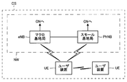
- FIG. 1 is a block diagram showing a radio communication system CS according to the first embodiment of the present invention.
- the radio communication system CS includes a macro base station eNB, a small base station PhNB, and a user apparatus UE as elements.
- the radio communication system CS may include elements (not shown) other than those described above, for example, an exchange, a serving gateway, a PDN gateway, and the like.
- the network NW includes elements other than the user apparatus UE among the elements included in the radio communication system CS.
- Each element in the radio communication system CS executes communication according to a predetermined access technology (Access Technology), for example, LTE / SAE (Long Term Evolution / System Architecture Evolution) standard included in 3GPP (Third Generation Partnership Project) standard.
- access Technology for example, LTE / SAE (Long Term Evolution / System Architecture Evolution) standard included in 3GPP (Third Generation Partnership Project) standard.
- LTE / SAE Long Term Evolution / System Architecture Evolution
- 3GPP Third Generation Partnership Project
- the user equipment UE is User Equipment
- the macro base station eNB is evolved Node B
- the switching center is Mobile Management Entity
- the serving gateway is Serving Gateway
- the PDN gateway Packet Data Network Gateway.
- the small base station PhNB is a new base station that performs wireless communication in a frequency band different from that of the macro base station eNB (details will be described later).
- the user apparatus UE can wirelessly communicate with the macro base station eNB and the small base station PhNB.
- Each base station (eNB, PhNB) is identified by a unique physical cell identifier PCI. As will be described later, each base station (eNB, PhNB) may be identified by a unique identification signal.
- a method of radio communication between the user apparatus UE and each base station (eNB, PhNB) is arbitrary. For example, OFDMA (Orthogonal Frequency Division Multiple Access) can be adopted in the downlink, and SC-FDMA (Single-Carrier Frequency Division Multiple Access) can be adopted in the uplink. It is also possible to adopt a configuration in which the wireless communication method used by the macro base station eNB and the wireless communication method used by the small base station PhNB are different.
- the macro base station eNB and the small base station PhNB are connected to each other by a wired interface such as an optical fiber capable of transmitting a clock signal.
- the macro base station eNB and the small base station PhNB can be synchronized with each other according to a clock signal.
- the clock signal may be generated in one of the base stations (preferably, in the macro base station eNB) and transmitted to the other base station, or may be arranged separately from each base station (not shown) It may be generated by the clock generator and transmitted to each base station.
- each of the macro base station eNB and the small base station PhNB is connected to the core network.
- the core network is a packet communication network having an exchange, a serving gateway, a PDN gateway, and the like.
- the small base station PhNB may be connected to the core network via the macro base station eNB instead of being directly connected to the core network.
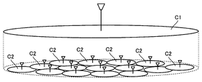
- FIG. 2 shows an example of a cell C formed around each base station (eNB, PhNB).
- the macro base station eNB forms a macro cell C1 around it
- the small base station PhNB forms a small cell C2 around it.
- the antenna of each base station is schematically shown.
- the plane in which the macro cell C1 is shown and the plane in which the small cell C2 are shown are drawn separately, but in reality, the macro cell C1 and the small cell C2 are superimposed on the same plane (the ground surface or the like). Can be done.
- Cell C is a range in which radio waves from each base station effectively reach the user apparatus UE. Therefore, the user apparatus UE can perform radio communication with the base station corresponding to the cell C in which the user apparatus UE is located.
- the small base station PhNB is smaller than the macro base station eNB and has a lower radio transmission capability (average transmission power, maximum transmission power, etc.). Further, the frequency band (second frequency band, for example, 3.5 GHz band) used by the small base station PhNB for wireless communication is higher than the frequency band (first frequency band, for example, 2 GHz band) used by the macro base station eNB for wireless communication. High frequency and large propagation loss. Therefore, the small cell C2 has a smaller area than the macro cell C1.
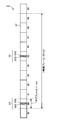
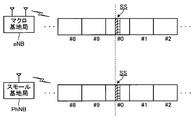
- FIG. 3 is a diagram illustrating a format of a radio frame F transmitted by each of the macro base station eNB and the small base station PhNB.
- Various radio signals (control signal, user signal, etc.) are mounted on the radio frame F and transmitted from the base stations (eNB, PhNB).
- One radio frame F includes 10 subframes SF. Since the time length of each subframe SF is 1 millisecond, the time length of one radio frame F is 10 milliseconds.
- Each subframe SF has any subframe number from # 0 to # 9 that is repeatedly given in the order of transmission.
- the synchronization signal SS indicating the physical cell identifier PCI is transmitted in the first and sixth subframes SF (SF # 0 and SF # 5) in the radio frame F. Therefore, the synchronization signal SS is transmitted at a period of 5 subframes (that is, every 5 milliseconds).
- the physical cell identifier PCI indicated in the synchronization signal SS is set for each base station (for each cell) and is used for various processes such as synchronization establishment, cell recognition, channel estimation, data scrambling, etc. (3GPP TS6.236.211 V10. 1.0 (2011-03), see Chapter 6.11, “Synchronization signals”).
- the synchronization signal SS includes a PSS (Primary Synchronization Signal) indicating the local identifier of the cell and an SSS (Secondary Synchronization Signal) indicating the group identifier of the cell. That is, the synchronization signal SS has a function as an identification signal.
- FIG. 4 is a diagram showing local identifiers and group identifiers included in the physical cell identifier PCI.
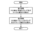
- FIG. 5 is a flowchart schematically showing the flow of synchronization establishment and cell recognition (cell search) using synchronization signals SS (PSS and SSS). is there.
- the cell search includes a first stage process and a second stage process.
- the user apparatus UE performs a correlation operation between the radio signal received from the base station (for example, the macro base station eNB) and the PSS replica signal stored in the user apparatus UE, and the radio signal PSS transmission timing (subframe timing) and local identifier included in the.
- the process of detecting the transmission timing (subframe timing) of the PSS may be referred to as “timing search process”.
- the user apparatus UE performs a correlation operation between the SSS included in the received radio signal and the SSS replica signal stored in the user apparatus UE based on the transmission timing detected in the first stage. To detect the SSS transmission timing (frame timing) and group identifier included in the radio signal. By the processing executed in the first stage and the second stage, the local identifier and group identifier indicated by the synchronization signal SS in the received radio signal are identified. As a result, the user apparatus UE recognizes the physical cell identifier PCI of the base station (eNB, PhNB) that transmits the synchronization signal SS.
- PCI physical cell identifier
- the user apparatus UE In the first stage, since the user apparatus UE does not recognize where the synchronization signal SS is located in the received radio signal, the user apparatus UE performs correlation calculation over the entire received radio signal.
- the user apparatus UE In the second stage, since the user apparatus can recognize the position of the synchronization signal SS (and thus SSS) in the received radio signal based on the transmission timing detected in the first stage, the user apparatus UE receives the received radio signal.
- the correlation calculation is executed only for the portion corresponding to SSS. Therefore, the arithmetic processing load of the first stage is significantly higher than the arithmetic processing load of the second stage.
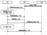
- FIG. 6 is an operation flow illustrating an example of the physical cell identifier PCI specifying process.
- FIG. 7 is a diagram illustrating an example of radio signal transmission by the macro base station eNB and the small base station PhNB that are synchronized with each other.
- the macro base station eNB and the small base station PhNB of the first embodiment are synchronized with each other. That is, as shown in FIG. 7, there is no difference between the transmission timing at which the macro base station eNB transmits the synchronization signal SS and the transmission timing at which the small base station PhNB transmits the synchronization signal SS (or above)
- the difference between the transmission timings is significantly smaller than the time length of the radio signal unit (resource element or the like).
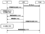
- the macro base station eNB periodically transmits a synchronization signal SS indicating a physical cell identifier PCI for identifying the macro base station eNB at a transmission timing as shown in FIGS. 3 and 7 (S10).
- the user apparatus UE Based on the synchronization signal SS received from the macro base station eNB, the user apparatus UE performs cell detection (processing for specifying a physical cell identifier PCI indicating the macro base station eNB) and synchronization establishment with the macro base station eNB. (S20). More specifically, as described above, based on the PSS included in the synchronization signal SS from the macro base station eNB, the user apparatus UE detects the transmission timing and local identifier of the PSS (first stage).
- the user apparatus UE detects the transmission timing and group identifier of the SSS, and specifies the transmission timing of the synchronization signal SS and the physical cell identifier PCI. Then, the user apparatus UE establishes a wireless connection with the macro base station eNB (S30).
- the macro base station eNB sends, to the user apparatus UE, synchronization state information regarding the synchronization state with the small base station PhNB located in the vicinity thereof and frequency information regarding the identification signal frequency used by the small base station PhNB for transmission of the synchronization signal SS. Notify (S40).
- the above synchronization state information indicates that the macro base station eNB and the small base station PhNB are synchronized.
- the user apparatus UE stores the received synchronization state information and frequency information.
- the small base station PhNB periodically transmits a synchronization signal SS indicating a physical cell identifier PCI for identifying the small base station PhNB at a transmission timing as shown in FIG. 7 (S50).
- the user apparatus UE performs cell detection (processing for specifying a physical cell identifier PCI indicating the small base station PhNB) based on the synchronization signal SS received from the small base station PhNB (S60).
- the above cell detection is performed using the synchronization state information and frequency information notified in step S40. More specifically, when the synchronization status information indicates that “the macro base station eNB and the small base station PhNB are synchronized”, the user apparatus UE does not perform the timing search process for the small base station PhNB.
- the local identifier and group identifier detection processing is executed for the identification signal frequency of the small base station PhNB indicated in the frequency information. Then, the user apparatus UE establishes a wireless connection with the small base station PhNB (S70).
- the user apparatus UE does not need to search for the position (transmission timing) of the synchronization signal SS included in the radio signal from the small base station PhNB. In other words, the user apparatus UE can omit the first stage of cell search.
- the user apparatus UE acquires the macro acquired in step S20. This is because the cell detection (correlation calculation with the replica signal) can be executed by regarding the transmission timing of the synchronization signal SS of the base station eNB as the transmission timing of the synchronization signal SS of the small base station PhNB.
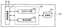
- FIG. 8 is a block diagram illustrating a configuration of the user device UE according to the first embodiment.
- the user apparatus UE includes a radio communication unit 110, a storage unit 120, and a control unit 130. Illustrations of an output device that outputs audio, video, and the like and an input device that receives an instruction from the user are omitted for convenience.
- the wireless communication unit 110 is an element for performing wireless communication with the macro base station eNB and the small base station PhNB, a transmission / reception antenna, a receiving circuit that receives a radio signal (radio wave) and converts it into an electrical signal, and a control A transmission circuit that converts electric signals such as signals and user signals into radio signals (radio waves) and transmits the signals.
- the storage unit 120 stores information related to communication control, in particular, the transmission timing of the synchronization signal SS of the base station (eNB, PhNB) that has established synchronization, and the above-described synchronization state information and frequency information.
- the control unit 130 includes a cell search unit 132 in addition to transmitting and receiving user signals and control signals.
- the cell search unit 132 performs the above-described plurality of cell searches, that is, the normal two-stage cell search (FIG. 5) and the cell search of the small base station PhNB using the transmission timing of the macro base station eNB (FIG. 6 and the like). To do.
- the control unit 130 and each element in the control unit 130 are configured by a CPU (Central Processing Unit) (not shown) in the user apparatus UE executing a computer program stored in the storage unit 120 and functioning according to the computer program. It is a functional block that is realized.
- a CPU Central Processing Unit
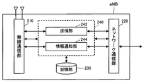
- FIG. 9 is a block diagram illustrating a configuration of the macro base station eNB according to the first embodiment.
- the macro base station eNB includes a radio communication unit 210, a network communication unit 220, a storage unit 230, and a control unit 240.
- the radio communication unit 210 is an element for executing radio communication with the user apparatus UE, and has the same configuration as the radio communication unit 110 of the user apparatus UE.
- the network communication unit 220 is an element for performing communication with other nodes (small base station PhNB, switching office, etc.) in the network NW, and transmits / receives signals to / from other nodes.
- the storage unit 230 stores information related to communication control.
- the control unit 240 includes a transmission unit 242 and an information notification unit 244 in addition to executing transmission / reception of user signals and control signals.
- the transmission unit 242 transmits the synchronization signal SS indicating the physical cell identifier PCI for identifying the macro base station eNB via the wireless communication unit 210.
- the information notification unit 244 notifies the user apparatus of the above-described synchronization state information and frequency information via the wireless communication unit 210.
- the control unit 240 and each element in the control unit 240 are functions realized by a CPU (not shown) in the macro base station eNB executing a computer program stored in the storage unit 230 and functioning according to the computer program. It is a block.
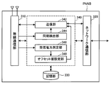
- FIG. 10 is a block diagram illustrating a configuration of the small base station PhNB according to the first embodiment.
- the small base station PhNB includes a wireless communication unit 310, a network communication unit 320, a storage unit 330, and a control unit 340.
- the radio communication unit 310 is an element for executing radio communication with the user apparatus UE, and has the same configuration as the radio communication unit 210 of the macro base station eNB.
- the network communication unit 320 is an element for executing communication with other nodes (such as the macro base station eNB) in the network NW, and transmits and receives signals to and from other nodes.
- the storage unit 330 stores information related to communication control.
- the control unit 340 includes a transmission unit 342 in addition to transmitting and receiving user signals and control signals.
- the transmission unit 342 transmits a synchronization signal SS indicating the physical cell identifier PCI for identifying the small base station PhNB via the wireless communication unit 310.
- the control unit 340 and each element in the control unit 340 are functions realized by a CPU (not shown) in the small base station PhNB executing a computer program stored in the storage unit 330 and functioning according to the computer program. It is a block.
- the user apparatus UE does not execute the timing search process for the small base station PhNB, based on the transmission timing of the synchronization signal SS of the macro base station eNB.
- the physical cell identifier PCI specified in the synchronization signal SS transmitted by the small base station PhNB can be executed.
- the timing search process for the small base station PhNB is omitted, the processing load for the user apparatus UE to recognize the small base station PhNB is reduced.
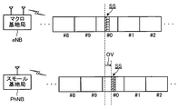
- the macro base station eNB and the small base station PhNB synchronize with each other and simultaneously transmit the synchronization signal SS.
- the transmission timing of the synchronization signal SS of the macro base station eNB is transmitted at a transmission timing that is transmitted for a time corresponding to the transmission offset value OV. 342) transmits the synchronization signal SS.
- step S12 to step S32 Cell detection and synchronization establishment (from step S12 to step S32) regarding the macro base station eNB performed by the user apparatus UE are the same as step S10 to step S30 of the first embodiment, and thus description thereof is omitted.
- the macro base station eNB sends, to the user apparatus UE, synchronization state information regarding the synchronization state with the small base station PhNB located in the vicinity thereof and frequency information regarding the identification signal frequency used by the small base station PhNB for transmission of the synchronization signal SS. Notify (S42).
- S42 Notify
- the transmission offset value OV with respect to the transmission timing is shown.
- the user apparatus UE stores the received synchronization state information and frequency information.
- the small base station PhNB periodically transmits a synchronization signal SS indicating a physical cell identifier PCI for identifying the small base station PhNB at a transmission timing as shown in FIG. 11 (S52).
- the user apparatus UE performs cell detection (processing for specifying a physical cell identifier PCI indicating the small base station PhNB) based on the synchronization signal SS received from the small base station PhNB (S62).
- the above cell detection is performed using the synchronization state information (transmission offset value OV) and frequency information notified in step S42.
- the user apparatus UE performs frequency search based on the transmission timing of the synchronization signal SS from the macro base station eNB and the transmission offset value OV without executing the timing search process for the small base station PhNB.
- a local identifier and group identifier detection process is executed for the identification signal frequency of the small base station PhNB shown.
- the user apparatus UE establishes a wireless connection with the small base station PhNB (S72).
- the user apparatus UE does not need to search for the position (transmission timing) of the synchronization signal SS included in the radio signal from the small base station PhNB. In other words, the user apparatus UE can omit the first stage of cell search.
- the user apparatus UE acquires in step S22. This is because the transmission timing of the synchronization signal SS of the small base station PhNB can be acquired by adding the transmission offset value OV to the transmission timing of the synchronization signal SS of the macro base station eNB. According to the above configuration, the same technical effects as those of the first embodiment are achieved.
- the macro base station eNB and the small base station PhNB are connected and synchronized with each other by an interface (such as an optical fiber) that can transmit a clock signal.
- the small base station PhNB receives the synchronization signal SS from the macro base station eNB and synchronizes with the macro base station eNB.
- FIG. 13 is a block diagram showing a radio communication system CS according to the third embodiment.
- the small base station PhNB receives the synchronization signal SS from the macro base station eNB, detects the transmission timing, and synchronizes with the macro base station eNB.
- the synchronization timing is delayed only by the time required for the radio signal transmitted from the macro base station eNB to reach the small base station PhNB and be processed. . Therefore, the small base station PhNB of the third embodiment advances the transmission timing of the synchronization signal SS according to the distance from the macro base station eNB.
- FIG. 14 is a block diagram showing a configuration of the small base station PhNB according to the third embodiment.
- the control unit 340 of the small base station PhNB further includes a synchronization detection unit 344, a received power measurement unit 346, and an offset value setting unit 348.
- the synchronization detection unit 344 detects the transmission timing of the synchronization signal SS from the macro base station eNB and supplies it to the transmission unit 342 in the same manner as the cell search unit 132 of the user apparatus UE of the above-described embodiment.
- the reception power measurement unit 346 measures reception power of a radio signal (reference signal) from the macro base station eNB received via the radio communication unit 310.
- the offset value setting unit 348 sets the transmission offset value OV to be larger as the reception power measured by the reception power measurement unit 346 is smaller, and supplies the transmission offset value OV to the transmission unit 342.
- the transmission unit 342 is configured to advance the transmission timing of the macro base station eNB supplied from the synchronization detection unit 344 by a transmission timing that is advanced by a time corresponding to the transmission offset value OV supplied from the offset value setting unit 348.
- a PhNB synchronization signal SS is transmitted.
- the small base station PhNB of the third embodiment increases the transmission timing earlier (advances earlier) as the reception power of the radio signal from the macro base station eNB is smaller. Transmission of the synchronization signal SS) is executed. Since the radio signal is attenuated as it propagates in space, the small reception power of the radio signal from the macro base station eNB in the small base station PhNB means that the distance from the macro base station eNB to the small base station PhNB is large. To do. Therefore, according to the above small base station PhNB, the transmission timing is corrected (advanced) according to the distance from the macro base station eNB. As a result, the difference between the transmission timing of the macro base station eNB and the transmission timing of the small base station PhNB is reduced.
- the transmission timing at which the macro base station eNB transmits the synchronization signal SS and the transmission timing at which the small base station PhNB transmits the synchronization signal SS are synchronized with each other (FIG. 7). Since 168 types of SSSs are not orthogonal to each other, they interfere with each other when a plurality of SSSs are transmitted at the same transmission timing. Therefore, when performing the cell search (FIG. 6) of the small base station PhNB using the transmission timing of the macro base station eNB described in the first embodiment, depending on the radio environment or the like, the group identifier (and thus the physical cell identifier PCI) ) May not be identified with sufficient accuracy.
- the small base station PhNB (transmission unit 342) of the fourth embodiment transmits a cell specific signal including a signal (identification signal) indicating a physical cell identifier PCI corresponding to the small base station PhNB.
- the cell specific signal is a signal different from the synchronization signal SS, for example, a reference signal other than the synchronization signal SS.
- Examples of the reference signal include CRS (Cell Specific Reference Signal), CSI-RS (CSI Reference Signal), PRS (Positioning Reference Signal), MBSFN-RS (MBSFN Reference Signal), and the like.
- CRS Cell Specific Reference Signal
- CSI-RS CSI Reference Signal
- PRS Positioning Reference Signal
- MBSFN-RS MBSFN Reference Signal
- CRS has 6 patterns of frequency shift
- symbols are spread over the entire system bandwidth in the CRS, more correlation energy can be acquired in the correlation calculation.
- any signal indicating the physical cell identifier PCI corresponding to the small base station PhNB may be adopted as the cell specific signal.
- the user apparatus UE (cell search unit 132) specifies the physical cell identifier PCI of the small base station PhNB indicated in the identification signal included in the cell specific signal in cell detection (step S60 in FIG. 6).
- the position (transmission timing) of the cell specific signal is determined as a relative position (transmission timing) with respect to the synchronization signal SS of the small base station PhNB. Further, as described above, the macro base station eNB and the small base station PhNB are synchronized, and the transmission timing of the synchronization signal SS of both is common.
- the user apparatus UE (cell search unit 132) regards the transmission timing of the synchronization signal SS of the macro base station eNB acquired in step S20 as the transmission timing of the synchronization signal SS of the small base station PhNB, and Cell detection can be performed on the signal.
- the user apparatus UE (cell search unit 132) may perform cell detection on a combination of the synchronization signal SS and the cell specific signal or a combination of a plurality of cell specific signals.
- the group identifier (physical cell identifier PCI) is used using only the SSSs that interfere with each other. It is possible to specify the group identifier (physical cell identifier PCI) with higher accuracy compared to the configuration for specifying.
- the fifth embodiment relates to details of cell search of the small base station PhNB using a reference signal (CSI-RS).
- the macro base station eNB (information notification unit 244) of the fifth embodiment in addition to the above-described synchronization state information and frequency information, information related to the configuration of CSI-RS transmitted by the small base station PhNB (reference signal configuration information, CSI -RS Configuration) and the CP length (cyclic prefix length) in wireless communication by the small base station PhNB are transmitted to the user apparatus UE.
- CSI-RS is a reference signal sequence generated using various parameters including physical cell identifier PCI. Radio resources (time and frequency) for transmitting the CSI-RS are not fixed and are determined independently of the physical cell identifier PCI (3GPP TS 36.211 V10.1.0 (2011-03), Chapter 6.11.1, Cell-specific reference signals). The above reference signal configuration information indicates a radio resource in which CSI-RS is transmitted.
- CP length is the cyclic prefix time length.
- the cyclic prefix is a guard interval that is inserted before an effective symbol in order to avoid the influence of a delayed wave during wireless communication using OFDM.
- the CP length is either “normal” or “extended”.
- the position of the SSS on the radio frame F is determined according to the CP length (not shown in FIGS. 3 and 7).
- the macro base station eNB (information notification unit 244) notifies the user apparatus UE of synchronization state information, frequency information, reference signal configuration information, and CP length information (S40).
- the frequency information of the present embodiment indicates the frequency used for transmission of the synchronization signal SS and the frequency used for transmission of the CSI-RS as identification signal frequencies.
- the small base station PhNB periodically transmits a synchronization signal SS indicating the physical cell identifier PCI for identifying the small base station PhNB and the CSI-RS described above (S50).
- the user apparatus UE performs cell detection based on the synchronization signal SS and CSI-RS received from the small base station PhNB (S60).
- the above cell detection is performed using synchronization state information, frequency information, reference signal configuration information, and CP length information. More specifically, when the synchronization status information indicates that “the macro base station eNB and the small base station PhNB are synchronized”, the user apparatus UE does not perform the timing search process for the small base station PhNB.
- the user apparatus UE Based on the transmission timing of the synchronization signal SS from the macro base station eNB and the reference signal configuration information, the local identifier, the group identifier, and the CSI-RS of the identification signal frequency of the small base station PhNB indicated in the frequency information Perform detection processing. Then, the user apparatus UE establishes a wireless connection with the small base station PhNB (S70).
- the above operation can also be applied to the configuration of the second embodiment in which the transmission timing of the small base station PhNB is offset.
- the above configuration can also be applied to arbitrary signals (other reference signals, small cell discovery signals (Discovery Signal), etc.) that can be used for cell identification.
- the user apparatus UE Since the user apparatus UE is notified of the reference signal configuration information from the macro base station eNB, the user apparatus UE recognizes the radio resource to which the CSI-RS is transmitted. Therefore, in the cell detection of step S60, the user apparatus UE performs CSI-RS detection processing (correlation calculation between the CSI-RS transmitted from the small base station PhNB and the replica signal stored in the user apparatus UE). Can be executed. Further, since the user equipment UE is notified of the CP length information from the macro base station eNB, the user apparatus UE recognizes the position of the SSS on the radio frame F (position relative to the PSS). Therefore, in the cell detection in step S60, the user apparatus UE does not need to specify whether the SSS position (transmission timing) corresponds to the “normal” CP length or the “extended” CP length.
- the same technical effects as those of the first embodiment are achieved. Furthermore, since the cell detection of the small base station PhNB is performed using the reference signal (CSI-RS), the cell can be identified with higher accuracy than the configuration in which the cell detection is performed using only the SSSs that interfere with each other. It becomes possible to do. Even if the small base station PhNB has a plurality of transmission points and each transmission point is identified by the reference signal (CSI-RS), according to the above configuration, not only the small base station PhNB but each It is also possible to identify the transmission point.
- CSI-RS reference signal
- the user apparatus UE (cell search unit 132) performs a detection process based on the transmission timing of the synchronization signal SS from the macro base station eNB instead of the first stage (timing search process) of the cell search for the small base station PhNB. (Tracking process) is executed. More specifically, in the cell detection (step S60 in FIG. 6) for the small base station PhNB, the user apparatus UE indicates that the synchronization state information is “the macro base station eNB and the small base station PhNB are synchronized”.
- the above situation is the same in the second embodiment in which the transmission timing of the small base station PhNB is offset. That is, when the accuracy of synchronization between the macro base station eNB and the small base station PhNB is low, the transmission timing (calculation in which the transmission timing of the macro base station eNB is delayed by the time corresponding to the transmission offset value OV indicated by the synchronization state information) There is a possibility that the transmission timing of the small base station PhNB) and the actual transmission timing of the synchronization signal SS from the small base station PhNB are shifted.
- the user apparatus UE performs transmission by delaying the transmission timing of the synchronization signal SS from the macro base station eNB by a time corresponding to the transmission offset value OV in the cell detection (step S62 in FIG. 12) for the small base station PhNB.
- Perform timing search processing over a predetermined period for example, 5 microseconds centered on the above transmission timing
- timing that is, calculation transmission timing of the small base station PhNB
- the cell detection is performed after the transmission timing of the small base station PhNB is specified.
- Seventh Embodiment A seventh embodiment of the present invention will be described below.
- a case is assumed in which a plurality of small base stations PhNB exist under the macro base station eNB.
- the plurality of small base stations PhNB are synchronized with the connected macro base station eNB.
- a plurality of small base stations PhNB transmit a common reference signal (for example, CSI-RS) at the same transmission timing.
- the above reference signals are synchronization reference signals used by the user apparatus UE to establish synchronization with the small base station PhNB.
- each of the plurality of small base stations PhNB transmits reference signals (for example, CSI-RS) having different transmission timings or sequences.
- the above reference signals are identification reference signals used for the user apparatus UE to identify the small base station PhNB.
- the macro base station eNB and the small base station PhNB are synchronized, only the macro base station eNB may transmit the above reference signal for synchronization. In this case, the small base station PhNB only needs to transmit an identification reference signal indicating itself.
- synchronization with a plurality of small base stations PhNB can be simultaneously detected by using a common synchronization reference signal. Furthermore, since each small base station PhNB transmits a different identification reference signal, the user apparatus UE can identify each small base station PhNB.
- FIG. 18 is a block diagram illustrating a configuration of a user apparatus UE according to the eighth embodiment.
- the control unit 130 of the user apparatus UE further includes a terminal transmission unit 134 that transmits a terminal detection signal indicating a terminal identifier for identifying the user apparatus.
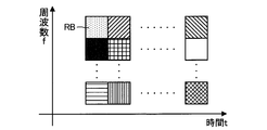
- FIG. 19 is an explanatory diagram of terminal detection signals transmitted by a plurality of user apparatuses UE.
- Each user apparatus UE (terminal transmission unit 134) transmits a terminal detection signal in the resource block RB allocated to the user apparatus UE.
- the hatching of the resource block RB corresponds to each different user apparatus UE.
- the terminal detection signal is an uplink signal transmitted using SC-FDMA. Reduction of the peak-to-average power ratio (PAPR) is realized by transmitting a signal from the user apparatus UE on a single carrier.
- PAPR peak-to-average power ratio
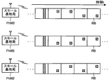
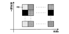
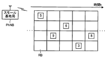
- FIG. 20 is an explanatory diagram of an identification signal transmitted by the small base station PhNB.
- the small base station PhNB (transmission unit 342) transmits an identification signal having a signal format common to the terminal detection signal transmitted by the user apparatus UE, in the plurality of resource blocks RB.
- “Common signal format” means that the signal length, the number of selectable signal sequences, the modulation / demodulation method used at the time of signal transmission / reception, and the like are common.
- the type of hatching of the resource block RB differs depending on the small base station PhNB that is the transmission source.
- a plurality of resource blocks RB may be transmitted on one time axis or on one frequency axis. According to the above configuration, the diversity effect in the time domain or the frequency domain by the plurality of resource blocks RB is realized.
- the identification signal transmitted by the small base station PhNB in the eighth embodiment is preferably transmitted using SC-FDMA.
- the above identification signal is preferably transmitted in a frequency band that can be received by the user apparatus UE. Therefore, when the uplink frequency and the downlink frequency are different in the small base station PhNB (that is, when FDD is adopted), the identification signal may be transmitted using SC-FDMA at the downlink frequency. In the above-described case where a plurality of resource blocks RB are transmitted on one frequency axis, a plurality of single carriers may be used for transmitting an identification signal.
- the identification signal may be transmitted at the common frequency. Further, the identification signal may be transmitted using a dedicated radio resource. In the dedicated radio resource, it is preferable that transmission of signals other than the identification signal is stopped.
- the terminal detection signal for detecting the user apparatus UE and the identification signal for detecting the small base station PhNB have a common signal format. Therefore, the user apparatus UE can perform detection of the small base station PhNB and detection of other user apparatuses UE by a single mechanism.
- cell detection of the small base station PhNB is performed using the reference signal (CSI-RS).
- cell detection of the small base station PhNB is performed based on a hopping pattern (identification signal pattern) configured by a plurality of CSI-RSs.
- the small base station PhNB (transmission unit 342) of the ninth embodiment transmits a CSI-RS according to a hopping pattern unique to the small base station PhNB.
- the hopping pattern indicates the arrangement of CSI-RSs in each of the plurality of subframes SF.
- the user apparatus UE can identify the small base station PhNB based on the arrangement (hopping pattern) of the CSI-RS over a plurality of subframes SF.
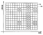
- FIG. 21 is an explanatory diagram of the arrangement of CSI-RSs in one resource block RB.
- a plurality of resource elements RE are included in the resource block RB.
- the CSI-RS is transmitted by one of resource elements RE (RE # 0 to RE # 19) numbered from 0 to 19 in FIG. 21 (a plurality of numbers may be selected).
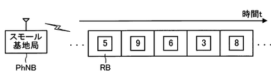
- FIG. 22 is a diagram showing a specific example of the hopping pattern.
- the small base station PhNB transmits CSI-RSs in the order of RE # 5-RE # 9-RE # 6-RE # 3-RE # 8 (hopping pattern).
- the user apparatus UE is notified of the hopping pattern used by each small base station PhNB from the macro base station eNB. Therefore, the user apparatus UE can identify the small base station PhNB by detecting the above hopping pattern.
- the repetition period of the hopping pattern may be set equal to the repetition period of the conventional CSI-RS (for example, 80 ms) or set to be equal to another period, for example, an integral multiple of the repetition period of the conventional CSI-RS. May be.
- a plurality of small base stations PhNB transmit a common synchronization CSI-RS, and each small base station PhNB transmits a different identification CSI-RS. May be.
- a base station PhNB can be installed.
- the radio communication system CS (network NW) of the above embodiment is a heterogeneous network including a macro base station eNB and a small base station PhNB, but only a single type of base station (for example, the macro base station eNB) is provided. A provided homogeneous network may be employed. In that case, one frequency band may be used.
- the macro base station eNB and the small base station PhNB are synchronized via an interface that can transmit a clock signal such as an optical fiber or a radio interface, but the macro base station eNB and the small base station PhNB are synchronized.
- the means for establishing is arbitrary.
- the macro base station eNB and the small base station PhNB may establish synchronization based on the time indicated by the radio wave (GPS signal) transmitted from the GPS satellite.
- GPS signal radio wave
- the macro base station eNB (information notification unit 244) notifies the user apparatus UE of an identifier list indicating physical cell identifiers PCI of a plurality of small base stations PhNB existing around the macro base station eNB in the synchronization state information. (Step S40, Step S42).
- the user apparatus UE (cell search unit 132) may perform cell detection (correlation calculation with a replica signal) only for the small base station PhNB corresponding to the physical cell identifier PCI indicated in the notified identifier list ( Step S60, Step S62). In the above case, since the number of cell identifiers PCI for performing cell detection is limited, the processing load of the user apparatus UE is further reduced.
- the small base station PhNB is identified by the physical cell identifier PCI, but the identifier for identifying the small base station PhNB is arbitrary. An identifier dedicated to identification of the small base station PhNB different from the physical cell identifier PCI may be adopted.
- Modification 5 There may be a plurality of small base stations PhNB under the control of one macro base station eNB. When there are a plurality of small base stations PhNB, the small base stations PhNB may transmit the synchronization signal SS in synchronization with each other, or may transmit the synchronization signal SS based on different transmission offset values OV. Also good. When a plurality of small base stations PhNB transmit the synchronization signal SS based on different transmission offset values OV, the macro base station eNB (information notification unit 244) notifies the user apparatus UE of each offset value OV as synchronization state information. To do.
- Modification 6 One reference signal configuration information (CSI-RS Configuration) may be set for a single small base station PhNB or a transmission point, or a plurality may be set. When a plurality of reference signal configuration information is set for a single small base station PhNB or a transmission point, the cell is specified with higher accuracy than when one reference signal configuration information is set. It becomes possible.
- CSI-RS Configuration CSI-RS Configuration
- the user apparatus UE performs a cell search (timing search process) using the synchronization signal SS.
- the user apparatus UE can execute a cell search (timing search process) using an arbitrary signal transmitted periodically.
- the reference signals (CRS, CSI-RS, PRS, MBSFN-RS, etc.) described in the fourth embodiment can be used for cell search.
- the cell search may be performed using a combination of the synchronization signal SS and the above reference signals, or a combination of a plurality of reference signals.
- a hopping pattern that hops not only the resource element RE in the subframe SF but also the resource block RB that transmits the CSI-RS may be employed. According to the above configuration, since more hopping patterns are provided, it is possible to install more small base stations PhNB.
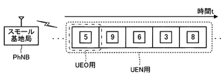
- Modification 9 In the ninth embodiment, as shown in FIG. 24, a new version user apparatus UEN for identifying the small base station PhNB and the CSI-RS are transmitted using the CSI-RS hopping pattern (“UEN” in FIG. 24). Both the old version user apparatus UEO that identifies the small base station PhNB based only on the resource element RE (for “UEO” in FIG. 24) may be mixed.
- the user apparatus UE is an arbitrary apparatus that can perform radio communication with the macro base station eNB and the small base station PhNB.
- the user apparatus UE may be, for example, a mobile phone terminal such as a feature phone or a smartphone, a desktop personal computer, a notebook personal computer, a UMPC (Ultra-Mobile Personal Computer), or a portable game machine. Other wireless terminals may be used.
- Each function executed by the CPU in each element (user apparatus UE, macro base station eNB, small base station PhNB) in the radio communication system CS may be executed by hardware instead of the CPU.
- FPGA programmable logic device
- DSP field programmable gate array
- DSP digital signal processor
Abstract
Description
1(1). 無線通信システムの概略
図1は、本発明の第1実施形態に係る無線通信システムCSを示すブロック図である。無線通信システムCSは、マクロ基地局eNBとスモール基地局PhNBとユーザ装置UEとを要素として備える。無線通信システムCSは、上記以外の不図示の要素、例えば、交換局、サービングゲートウェイ、及びPDNゲートウェイ等を備え得る。ネットワークNWは、無線通信システムCSが備える上記の要素のうち、ユーザ装置UE以外の要素を備える。
図3は、マクロ基地局eNBおよびスモール基地局PhNBの各々が送信する無線フレームFのフォーマットを示す図である。種々の無線信号(制御信号、ユーザ信号等)が無線フレームFに搭載されて基地局(eNB,PhNB)から送信される。1つの無線フレームFは10個のサブフレームSFを含む。各サブフレームSFの時間長は1ミリ秒であるから、1つの無線フレームFの時間長は10ミリ秒である。各サブフレームSFは、送信順に繰り返して付される#0から#9までのいずれかのサブフレーム番号を有する。物理セル識別子PCIを示す同期信号SSは、無線フレームF内の1番目および6番目のサブフレームSF(SF#0およびSF#5)において送信される。したがって、同期信号SSは5サブフレーム周期で(すなわち5ミリ秒ごとに)送信される。
1(3)-1. 同期信号を用いた同期確立およびセル認識(セルサーチ)の概略
図5は、同期信号SS(PSSおよびSSS)を用いた同期確立およびセル認識(セルサーチ)の流れを概略的に示すフロー図である。セルサーチは第1段階および第2段階の処理を含む。第1段階では、ユーザ装置UEが、基地局(例えば、マクロ基地局eNB)から受信した無線信号と、ユーザ装置UEに記憶されているPSSのレプリカ信号との相関演算を実行して、無線信号に含まれるPSSの送信タイミング(サブフレームタイミング)およびローカル識別子を検出する。なお、PSSの送信タイミング(サブフレームタイミング)を検出する処理を「タイミングサーチ処理」と称する場合がある。
図6および図7を参照して、本実施形態におけるスモール基地局PhNBの物理セル識別子PCIの特定処理を説明する。図6は、物理セル識別子PCIの特定処理の一例を示す動作フローである。図7は、相互に同期するマクロ基地局eNBとスモール基地局PhNBとによる無線信号の送信の一例を示す図である。
1(4)-1. ユーザ装置の構成
図8は、第1実施形態に係るユーザ装置UEの構成を示すブロック図である。ユーザ装置UEは、無線通信部110と記憶部120と制御部130とを備える。音声・映像等を出力する出力装置及びユーザからの指示を受け付ける入力装置等の図示は便宜的に省略されている。無線通信部110は、マクロ基地局eNBおよびスモール基地局PhNBと無線通信を実行するための要素であり、送受信アンテナと、無線信号(電波)を受信して電気信号に変換する受信回路と、制御信号、ユーザ信号等の電気信号を無線信号(電波)に変換して送信する送信回路とを含む。記憶部120は、通信制御に関する情報、特に、同期を確立した基地局(eNB,PhNB)の同期信号SSの送信タイミング、ならびに、前述の同期状態情報および周波数情報を記憶する。制御部130は、ユーザ信号および制御信号の送受信を実行する他、セルサーチ部132を備える。セルサーチ部132は、前述した複数のセルサーチ、すなわち、通常の2段階セルサーチ(図5)およびマクロ基地局eNBの送信タイミングを用いたスモール基地局PhNBのセルサーチ(図6等)を実行する。制御部130及び制御部130内の各要素は、ユーザ装置UE内の不図示のCPU(Central Processing Unit)が、記憶部120に記憶されたコンピュータプログラムを実行し、そのコンピュータプログラムに従って機能することにより実現される機能ブロックである。
図9は、第1実施形態に係るマクロ基地局eNBの構成を示すブロック図である。マクロ基地局eNBは、無線通信部210とネットワーク通信部220と記憶部230と制御部240とを備える。無線通信部210は、ユーザ装置UEと無線通信を実行するための要素であり、ユーザ装置UEの無線通信部110と同様の構成を有する。ネットワーク通信部220は、ネットワークNW内の他のノード(スモール基地局PhNB、交換局等)と通信を実行するための要素であり、他のノードと信号を送受信する。記憶部230は、通信制御に関する情報を記憶する。制御部240は、ユーザ信号および制御信号の送受信を実行する他、送信部242と情報通知部244とを備える。送信部242は、マクロ基地局eNBを識別する物理セル識別子PCIを示す同期信号SSを、無線通信部210を介して送信する。情報通知部244は、前述の同期状態情報および周波数情報を、無線通信部210を介してユーザ装置に通知する。制御部240及び制御部240内の各要素は、マクロ基地局eNB内の不図示のCPUが、記憶部230に記憶されたコンピュータプログラムを実行し、そのコンピュータプログラムに従って機能することにより実現される機能ブロックである。
図10は、第1実施形態に係るスモール基地局PhNBの構成を示すブロック図である。スモール基地局PhNBは、無線通信部310とネットワーク通信部320と記憶部330と制御部340とを備える。無線通信部310は、ユーザ装置UEと無線通信を実行するための要素であり、マクロ基地局eNBの無線通信部210と同様の構成を有する。ネットワーク通信部320は、ネットワークNW内の他のノード(マクロ基地局eNB等)と通信を実行するための要素であり、他のノードと信号を送受信する。記憶部330は、通信制御に関する情報を記憶する。制御部340は、ユーザ信号および制御信号の送受信を実行する他、送信部342を備える。送信部342は、スモール基地局PhNBを識別する物理セル識別子PCIを示す同期信号SSを、無線通信部310を介して送信する。制御部340及び制御部340内の各要素は、スモール基地局PhNB内の不図示のCPUが、記憶部330に記憶されたコンピュータプログラムを実行し、そのコンピュータプログラムに従って機能することにより実現される機能ブロックである。
以上の本実施形態の構成によれば、ユーザ装置UEは、スモール基地局PhNBに対するタイミングサーチ処理を実行しなくても、マクロ基地局eNBの同期信号SSの送信タイミングに基づいて、スモール基地局PhNBが送信する同期信号SSに示される物理セル識別子PCIの特定処理を実行することが可能である。結果として、スモール基地局PhNBに対するタイミングサーチ処理が省略されるので、ユーザ装置UEがスモール基地局PhNBを認識するための処理負荷が低減される。
本発明の第2実施形態を以下に説明する。以下に例示する各実施形態において、作用、機能が第1実施形態と同等である要素については、以上の説明で参照した符号を流用して各々の説明を適宜に省略する。
以上の構成によれば、第1実施形態と同様の技術的効果が奏される。
本発明の第3実施形態を以下に説明する。第1実施形態では、マクロ基地局eNBとスモール基地局PhNBとが、クロック信号を伝送可能なインタフェース(光ファイバ等)によって相互に接続され相互に同期する。第3実施形態では、スモール基地局PhNBが、マクロ基地局eNBからの同期信号SSを受信して、マクロ基地局eNBと同期する。
本発明の第4実施形態を以下に説明する。第1実施形態では、マクロ基地局eNBが同期信号SSを送信する送信タイミングと、スモール基地局PhNBが同期信号SSを送信する送信タイミングとが相互に同期している(図7)。168種類のSSSは互いに直交していないので、複数のSSSが同じ送信タイミングで送信されると互いに干渉する。したがって、第1実施形態にて説明されたマクロ基地局eNBの送信タイミングを用いたスモール基地局PhNBのセルサーチ(図6)を実行する場合、無線環境等によってはグループ識別子(ひいては物理セル識別子PCI)を十分な精度で特定できない可能性がある。
本発明の第5実施形態を以下に説明する。第5実施形態は、参照信号(CSI-RS)を用いたスモール基地局PhNBのセルサーチの詳細に関する。第5実施形態のマクロ基地局eNB(情報通知部244)は、前述の同期状態情報および周波数情報に加えて、スモール基地局PhNBが送信するCSI-RSの構成に関する情報(参照信号構成情報、CSI-RS Configuration)と、スモール基地局PhNBによる無線通信におけるCP長(サイクリックプレフィックス長)とを、ユーザ装置UEに送信する。
本発明の第6実施形態を以下に説明する。マクロ基地局eNBとスモール基地局PhNBとの同期は、常に厳密であるとは限らない。マクロ基地局eNBとスモール基地局PhNBとの同期の精度が低い場合も想定され得る。そのような場合、第1実施形態のように前述の同期状態情報が「マクロ基地局eNBとスモール基地局PhNBとが同期している」ことを示していても、実際には、マクロ基地局eNBからの同期信号SSの送信タイミングと、スモール基地局PhNBからの同期信号SSの送信タイミングとがずれている可能性がある。
本発明の第7実施形態を以下に説明する。第7実施形態では、図15に示すように、マクロ基地局eNBの配下に複数のスモール基地局PhNBが存在するケースを想定する。これら複数のスモール基地局PhNBは、接続先のマクロ基地局eNBと同期している。
本発明の第8実施形態を以下に説明する。第8実施形態では、図17に示すように、無線通信システムCSにおいて、ユーザ装置UE同士が直接的に無線通信を実行する。図18は、第8実施形態に係るユーザ装置UEの構成を示すブロック図である。ユーザ装置UEの制御部130は、そのユーザ装置を識別する端末識別子を示す端末検出信号を送信する端末送信部134をさらに備える。
また、専用の無線リソースを用いて識別信号が送信されてもよい。専用の無線リソースにおいては、識別信号以外の信号の送信が停止されると好適である。
本発明の第9実施形態を以下に説明する。第5実施形態では、参照信号(CSI-RS)を用いてスモール基地局PhNBのセル検出が実行される。第9実施形態では、複数のCSI-RSにより構成されるホッピングパターン(識別信号パターン)に基づいてスモール基地局PhNBのセル検出が実行される。
以上の実施の形態は多様に変形される。具体的な変形の態様を以下に例示する。以上の実施の形態および以下の例示から任意に選択された2以上の態様は、相互に矛盾しない限り適宜に併合され得る。
以上の実施形態の無線通信システムCS(ネットワークNW)は、マクロ基地局eNBとスモール基地局PhNBとを備えるヘテロジーニアスネットワークであるが、単一種別の基地局(例えば、マクロ基地局eNB)のみを備えるホモジーニアスネットワークが採用されてもよい。その場合、使用される周波数帯域は1つであってもよい。
以上の実施形態では、光ファイバ等のクロック信号を伝送可能なインタフェースまたは無線インタフェースを介してマクロ基地局eNBとスモール基地局PhNBとが同期するが、マクロ基地局eNBとスモール基地局PhNBとが同期を確立するための手段は任意である。例えば、GPS衛星から送信される電波(GPS信号)が示す時刻に基づいて、マクロ基地局eNBとスモール基地局PhNBとが同期を確立してもよい。
マクロ基地局eNB(情報通知部244)が、そのマクロ基地局eNBの周辺に存在する複数のスモール基地局PhNBの物理セル識別子PCIを示す識別子リストを、同期状態情報に含めてユーザ装置UEに通知してもよい(ステップS40、ステップS42)。ユーザ装置UE(セルサーチ部132)は、通知された識別子リストに示される物理セル識別子PCIに対応するスモール基地局PhNBのみを対象としてセル検出(レプリカ信号との相関演算)を実行すればよい(ステップS60、ステップS62)。以上の場合、セル検出を実行すべきセル識別子PCIの数が限定されるので、ユーザ装置UEの処理負荷がより低減される。
以上の実施形態では、スモール基地局PhNBが物理セル識別子PCIによって識別されるが、スモール基地局PhNBを識別するための識別子は任意である。物理セル識別子PCIとは異なるスモール基地局PhNB識別専用の識別子が採用されてもよい。
1つのマクロ基地局eNBの配下に複数のスモール基地局PhNBが存在し得る。複数のスモール基地局PhNBが存在する場合、それらのスモール基地局PhNBは相互に同期して同期信号SSを送信してもよいし、それぞれ異なる送信オフセット値OVに基づいて同期信号SSを送信してもよい。複数のスモール基地局PhNBがそれぞれ異なる送信オフセット値OVに基づいて同期信号SSを送信する場合、マクロ基地局eNB(情報通知部244)は、各オフセット値OVを同期状態情報としてユーザ装置UEに通知する。
参照信号構成情報(CSI-RS Configuration)は、単一のスモール基地局PhNBまたは送信点に対して1つ設定されてもよいし、複数設定されてもよい。複数の参照信号構成情報が単一のスモール基地局PhNBまたは送信点に対して設定される場合には、1つの参照信号構成情報が設定される場合と比較して、より精度高くセルを特定することが可能となる。
第6実施形態では、ユーザ装置UEが同期信号SSを用いてセルサーチ(タイミングサーチ処理)を実行する。しかし、ユーザ装置UEは、周期的に送信される任意の信号を用いてセルサーチ(タイミングサーチ処理)を実行することが可能である。例えば、第4実施形態において説明された参照信号(CRS,CSI-RS,PRS,MBSFN-RS等)がセルサーチに用いられ得る。また、同期信号SSと以上の参照信号の組合せ、または複数の参照信号の組合せを用いてセルサーチが実行されてもよい。
第9実施形態に関して、図23に示すように、サブフレームSF内のリソースエレメントREだけでなく、CSI-RSを送信するリソースブロックRBをもホッピングさせるホッピングパターンが採用されてもよい。以上の構成によれば、より多くのホッピングパターンが提供されるので、より多くのスモール基地局PhNBを設置することが可能である。
第9実施形態において、図24に示すように、CSI-RSのホッピングパターン(図24の「UEN用」)にてスモール基地局PhNBを識別する新バージョンユーザ装置UENと、CSI-RSが送信されるリソースエレメントRE(図24の「UEO用」)のみに基づいてスモール基地局PhNBを識別する旧バージョンユーザ装置UEOとの双方が混在してもよい。
ユーザ装置UEは、マクロ基地局eNBおよびスモール基地局PhNBと無線通信が可能な任意の装置である。ユーザ装置UEは、例えば、フィーチャーフォンまたはスマートフォン等の携帯電話端末でもよく、デスクトップ型パーソナルコンピュータでもよく、ノート型パーソナルコンピュータでもよく、UMPC(Ultra-Mobile Personal Computer)でもよく、携帯用ゲーム機でもよく、その他の無線端末でもよい。
無線通信システムCS内の各要素(ユーザ装置UE、マクロ基地局eNB、スモール基地局PhNB)においてCPUが実行する各機能は、CPUの代わりに、ハードウェアで実行してもよいし、例えばFPGA(Field Programmable Gate Array)、DSP(Digital Signal Processor)等のプログラマブルロジックデバイスで実行してもよい。
Claims (10)
- 第1周波数帯域にて無線通信を実行可能であり、第1セル識別子によって識別される第1基地局と、第2周波数帯域にて無線通信を実行可能であり、第2セル識別子によって識別される第2基地局と、を含む複数の基地局と、
前記複数の基地局の各々と無線通信を実行可能なユーザ装置とを備え、
前記第1基地局は、
当該第1基地局を識別する前記第1セル識別子を示す第1同期信号を第1送信タイミングにて送信する第1送信部を備え、
前記第2基地局は、
当該第2基地局を識別する前記第2セル識別子を示す識別信号を送信する第2送信部を備え、
前記ユーザ装置は、
前記第1基地局から受信した前記第1同期信号に基づいて前記第1送信タイミングを検出し、前記第1基地局との同期を確立するタイミングサーチ処理を実行するセルサーチ部を備え、
前記第1基地局は、
当該第1基地局と前記第2基地局との同期状態に関する同期状態情報と、前記第2周波数帯域のうち前記第2基地局が前記識別信号の送信に用いる識別信号周波数に関する周波数情報とを、前記ユーザ装置に通知する情報通知部を備え、
前記ユーザ装置の前記セルサーチ部は、
前記周波数情報に示される前記識別信号周波数に対して、前記識別信号に示される前記第2セル識別子の特定処理を、前記第1基地局からの前記同期状態情報に基づいて実行する
無線通信システム。 - 前記第1基地局および前記第2基地局は相互に同期して無線通信を実行可能であり、
前記第2基地局の前記第2送信部は第2送信タイミングにて第2同期信号を送信し、
前記第1基地局の前記情報通知部が通知する前記同期状態情報は、前記第1基地局と前記第2基地局とが同期しているか否かを示し、
前記ユーザ装置の前記セルサーチ部は、前記第1基地局と前記第2基地局とが同期していると前記同期状態情報が示す場合、前記第2基地局に対するタイミングサーチ処理を実行せずに、前記第1送信タイミングに基づいて、前記識別信号に示される前記第2セル識別子の特定処理を実行する
請求項1の無線通信システム。 - 前記第1基地局および前記第2基地局は相互に同期して無線通信を実行可能であり、
前記第2基地局の前記第2送信部は第2送信タイミングにて第2同期信号を送信し、
前記第1基地局の前記情報通知部が通知する前記同期状態情報は、前記第1基地局と前記第2基地局とが同期しているか否かを示し、
前記ユーザ装置の前記セルサーチ部は、前記第1基地局と前記第2基地局とが同期していると前記同期状態情報が示す場合、前記第1送信タイミングを含む所定期間にわたって前記第2基地局に対するタイミングサーチ処理を実行することにより前記第2送信タイミングを特定し、前記第2送信タイミングに基づいて前記識別信号に示される前記第2セル識別子の特定処理を実行する
請求項1の無線通信システム。 - 前記第2基地局の前記第2送信部は、前記第1基地局の前記第1送信タイミングを送信オフセット値に対応する時間だけ遅らせた前記第2送信タイミングにて、前記識別信号を含む第2同期信号を送信し、
前記第1基地局の前記情報通知部が通知する前記同期状態情報は、前記第1基地局の前記第1送信タイミングに対する前記送信オフセット値を示し、
前記ユーザ装置の前記セルサーチ部は、前記第1送信タイミングと前記同期状態情報が示す前記送信オフセット値とに基づいて、前記第2基地局に対するタイミングサーチ処理を実行せずに、前記識別信号に示される前記第2セル識別子の特定処理を実行する
請求項1の無線通信システム。 - 前記第2基地局の前記第2送信部は、前記第1基地局の前記第1送信タイミングを送信オフセット値に対応する時間だけ遅らせた前記第2送信タイミングにて、前記識別信号を含む第2同期信号を送信し、
前記第1基地局の前記情報通知部が通知する前記同期状態情報は、前記第1基地局の前記第1送信タイミングに対する前記送信オフセット値を示し、
前記ユーザ装置の前記セルサーチ部は、前記第1送信タイミングを、前記同期状態情報が示す前記送信オフセット値に対応する時間だけ遅らせた送信タイミングを含む所定期間にわたって前記第2基地局に対するタイミングサーチ処理を実行することにより前記第2送信タイミングを特定し、前記第2送信タイミングに基づいて前記識別信号に示される前記第2セル識別子の特定処理を実行する
請求項1の無線通信システム。 - 前記第2基地局は、さらに、
前記第1基地局から受信した無線信号の受信電力を測定する受信電力測定部と、
前記受信電力測定部が測定した前記受信電力が小さいほど、送信オフセット値を大きく設定するオフセット値設定部とを備え、
前記第2基地局の前記第2送信部は、前記第1基地局の前記第1送信タイミングを送信オフセット値に対応する時間だけ早めた前記第2送信タイミングにて、前記識別信号を含む第2同期信号を送信し、
前記第1基地局の前記情報通知部が通知する前記同期状態情報は、前記第1基地局と前記第2基地局とが同期しているか否かを示し、
前記ユーザ装置の前記セルサーチ部は、前記第1基地局と前記第2基地局とが同期していると前記同期状態情報が示す場合、前記第2基地局に対するタイミングサーチ処理を実行せずに、前記第1送信タイミングに基づいて、前記識別信号に示される前記第2セル識別子の特定処理を実行する
請求項1の無線通信システム。 - 前記同期状態情報は、さらに、複数の前記第2基地局に対応する複数の前記第2セル識別子を示す識別子リストを含み、
前記ユーザ装置の前記セルサーチ部は、前記識別子リストに示される複数の前記第2セル識別子に対応する複数の前記第2基地局のみについて、前記特定処理を実行する
請求項2の無線通信システム。 - 前記ユーザ装置は、
当該ユーザ装置を識別する端末識別子を示す端末検出信号を送信する端末送信部を備え、
前記第2基地局の前記第2送信部は、
前記端末検出信号と共通の信号フォーマットを有する前記識別信号を送信する
請求項1の無線通信システム。 - 前記第2基地局の前記第2送信部は、
複数のサブフレームの各々における前記識別信号の配置を示し、当該第2基地局を識別する識別信号パターンに従って前記識別信号を送信する
請求項1の無線通信システム。 - 第1周波数帯域にて無線通信を実行可能であり、第1セル識別子によって識別される第1基地局と、第2周波数帯域にて無線通信を実行可能であり、第2セル識別子によって識別される第2基地局と、を含む複数の基地局と、
前記複数の基地局の各々と無線通信を実行可能なユーザ装置とを備える無線通信システムの通信制御方法であって、
前記第1基地局において、当該第1基地局を識別する前記第1セル識別子を示す第1同期信号を第1送信タイミングにて送信することと、
前記第2基地局において、当該第2基地局を識別する前記第2セル識別子を示す識別信号を送信することと、
前記ユーザ装置において、前記第1基地局から受信した前記第1同期信号に基づいて前記第1送信タイミングを検出し、前記第1基地局との同期を確立するタイミングサーチ処理を実行することと、
前記第1基地局において、当該第1基地局と前記第2基地局との同期状態に関する同期状態情報と、前記第2周波数帯域のうち前記第2基地局が前記識別信号の送信に用いる識別信号周波数に関する周波数情報とを、前記ユーザ装置に通知することと、
前記ユーザ装置において、前記周波数情報に示される前記識別信号周波数に対して、前記識別信号に含まれる前記第2セル識別子の特定処理を、前記第1基地局からの前記同期状態情報を用いて実行することとを備える
通信制御方法。
Priority Applications (4)
| Application Number | Priority Date | Filing Date | Title |
|---|---|---|---|
| EP13870740.1A EP2945428B1 (en) | 2013-01-09 | 2013-10-22 | Radio communication system and communication control method |
| BR112015012836A BR112015012836A2 (pt) | 2013-01-09 | 2013-10-22 | sistema de comunicação de rádio e método de controle de comunicação |
| CN201380069976.8A CN105122891B (zh) | 2013-01-09 | 2013-10-22 | 无线通信系统和通信控制方法 |
| US14/759,257 US9603111B2 (en) | 2013-01-09 | 2013-10-22 | Radio communication system and communication control method |
Applications Claiming Priority (4)
| Application Number | Priority Date | Filing Date | Title |
|---|---|---|---|
| JP2013-001826 | 2013-01-09 | ||
| JP2013001826 | 2013-01-09 | ||
| JP2013-099391 | 2013-05-09 | ||
| JP2013099391A JP5809660B2 (ja) | 2013-01-09 | 2013-05-09 | 無線通信システムおよび通信制御方法 |
Publications (1)
| Publication Number | Publication Date |
|---|---|
| WO2014109105A1 true WO2014109105A1 (ja) | 2014-07-17 |
Family
ID=51166770
Family Applications (1)
| Application Number | Title | Priority Date | Filing Date |
|---|---|---|---|
| PCT/JP2013/078531 WO2014109105A1 (ja) | 2013-01-09 | 2013-10-22 | 無線通信システムおよび通信制御方法 |
Country Status (6)
| Country | Link |
|---|---|
| US (1) | US9603111B2 (ja) |
| EP (1) | EP2945428B1 (ja) |
| JP (1) | JP5809660B2 (ja) |
| CN (1) | CN105122891B (ja) |
| BR (1) | BR112015012836A2 (ja) |
| WO (1) | WO2014109105A1 (ja) |
Cited By (5)
| Publication number | Priority date | Publication date | Assignee | Title |
|---|---|---|---|---|
| WO2016013387A1 (ja) * | 2014-07-23 | 2016-01-28 | 株式会社Nttドコモ | 無線基地局、ユーザ端末及び無線通信方法 |
| CN106304346A (zh) * | 2015-05-15 | 2017-01-04 | 电信科学技术研究院 | 一种同步信号的发送、接收方法及装置 |
| CN106576256A (zh) * | 2014-07-31 | 2017-04-19 | 宇龙计算机通信科技(深圳)有限公司 | 时频同步维持的方法、时频同步维持的系统和终端 |
| WO2017084607A1 (zh) * | 2015-11-20 | 2017-05-26 | 华为技术有限公司 | 一种下行同步的方法、装置及系统 |
| JP2017530595A (ja) * | 2014-08-11 | 2017-10-12 | インテル アイピー コーポレイション | 高周波数帯域無線アクセス技術アーキテクチャにおけるシステム検出 |
Families Citing this family (22)
| Publication number | Priority date | Publication date | Assignee | Title |
|---|---|---|---|---|
| JP2015223005A (ja) * | 2013-01-09 | 2015-12-10 | 株式会社Nttドコモ | 無線通信システムおよび通信制御方法 |
| EP2963982B1 (en) * | 2013-02-28 | 2019-03-20 | Sony Corporation | Communication control device, communication control method, and user equipment |
| KR101460491B1 (ko) * | 2013-04-03 | 2014-11-11 | 주식회사 이노와이어리스 | 멀티-셀 환경에서 lte 셀 검출 장치 |
| US9603065B2 (en) | 2013-04-03 | 2017-03-21 | Google Technology Holdings LLC | Methods and devices for cell discovery |
| WO2015013208A1 (en) * | 2013-07-22 | 2015-01-29 | Zte Wistron Telecom Ab | Cell synchronization and synchronization cell indication |
| JP6309736B2 (ja) * | 2013-10-09 | 2018-04-11 | 株式会社Nttドコモ | 無線基地局、ユーザ端末及び無線通信方法 |
| IN2013CH05862A (ja) * | 2013-12-16 | 2015-06-19 | Samsung R&D Inst India – Bangalore Private Ltd | |
| WO2015180188A1 (zh) * | 2014-05-30 | 2015-12-03 | 华为技术有限公司 | 同步方法、同步装置和基站 |
| US9374796B2 (en) * | 2014-10-10 | 2016-06-21 | Qualcomm Incorporated | Channel structure for a cellular internet of things system |
| US10091609B2 (en) * | 2016-03-28 | 2018-10-02 | Qualcomm Incorporated | Enhancing PRS searches via runtime conditions |
| KR102614082B1 (ko) | 2016-07-01 | 2023-12-13 | 광동 오포 모바일 텔레커뮤니케이션즈 코포레이션 리미티드 | 신호 검출 방법 및 장치 |
| US10893445B2 (en) | 2016-09-30 | 2021-01-12 | Telefonaktiebolaget Lm Ericsson (Publ) | Network, network nodes and method therein for handling connection in a wireless communication network |
| US10517009B2 (en) * | 2016-09-30 | 2019-12-24 | Telefonaktiebolaget Lm Ericsson (Publ) | Network, network node, user equipment and method therein for establishing active mode beam to idle mode cells neighbour relations in a wireless communication network |
| CN107959646B (zh) * | 2016-10-15 | 2020-11-06 | 上海朗帛通信技术有限公司 | 一种支持同步信号的ue、基站中的方法和装置 |
| CN108616300B (zh) * | 2017-01-06 | 2024-03-08 | 华为技术有限公司 | 一种信道状态信息测量的配置方法及相关设备 |
| JP6832794B2 (ja) * | 2017-06-05 | 2021-02-24 | ルネサスエレクトロニクス株式会社 | 無線通信システム |
| WO2019043799A1 (ja) * | 2017-08-29 | 2019-03-07 | 株式会社Nttドコモ | ユーザ端末、基地局及び無線通信方法 |
| WO2019068587A1 (en) * | 2017-10-02 | 2019-04-11 | Sony Mobile Communications Inc | METHOD AND DEVICE FOR SYNCHRONIZATION AND MEASUREMENT IN A RADIO COMMUNICATION SYSTEM |
| WO2019125749A1 (en) * | 2017-12-18 | 2019-06-27 | Kyocera Corporation | Reduced system acquisition time for mtc using common synchronization channel |
| JP7037653B2 (ja) * | 2017-12-18 | 2022-03-16 | 京セラ株式会社 | 共通同期信号取得のためにアドバンスさせたダウンリンクタイミング |
| TW201931813A (zh) * | 2018-01-09 | 2019-08-01 | 財團法人資訊工業策進會 | 無線通訊裝置及其時頻同步方法與非暫態電腦可讀取紀錄媒體 |
| US11109387B2 (en) * | 2019-02-15 | 2021-08-31 | Nokia Technologies Oy | Interference management |
Citations (3)
| Publication number | Priority date | Publication date | Assignee | Title |
|---|---|---|---|---|
| JP2009188612A (ja) | 2008-02-05 | 2009-08-20 | Mitsubishi Electric Corp | 移動体通信システム |
| JP2010045545A (ja) * | 2008-08-11 | 2010-02-25 | Ntt Docomo Inc | ユーザ装置及びセルサーチ方法 |
| JP2012191444A (ja) * | 2011-03-10 | 2012-10-04 | Ntt Docomo Inc | セルサーチ装置及び方法並びに移動局 |
Family Cites Families (4)
| Publication number | Priority date | Publication date | Assignee | Title |
|---|---|---|---|---|
| US8711811B2 (en) * | 2008-06-19 | 2014-04-29 | Telefonaktiebolaget L M Ericsson (Publ) | Identifying multi-component carrier cells |
| CA2859980C (en) * | 2008-12-26 | 2016-04-12 | Sharp Kabushiki Kaisha | Base station device, mobile station device, communication system, and communication method |
| US9072104B2 (en) * | 2009-02-02 | 2015-06-30 | Mitsubishi Electric Corporation | Mobile communication system |
| CN102958151B (zh) * | 2011-08-15 | 2015-08-19 | 财团法人工业技术研究院 | 载波聚合的无线网络系统与基站、通信装置及同步方法 |
-
2013
- 2013-05-09 JP JP2013099391A patent/JP5809660B2/ja active Active
- 2013-10-22 BR BR112015012836A patent/BR112015012836A2/pt not_active IP Right Cessation
- 2013-10-22 US US14/759,257 patent/US9603111B2/en active Active
- 2013-10-22 WO PCT/JP2013/078531 patent/WO2014109105A1/ja active Application Filing
- 2013-10-22 EP EP13870740.1A patent/EP2945428B1/en active Active
- 2013-10-22 CN CN201380069976.8A patent/CN105122891B/zh active Active
Patent Citations (3)
| Publication number | Priority date | Publication date | Assignee | Title |
|---|---|---|---|---|
| JP2009188612A (ja) | 2008-02-05 | 2009-08-20 | Mitsubishi Electric Corp | 移動体通信システム |
| JP2010045545A (ja) * | 2008-08-11 | 2010-02-25 | Ntt Docomo Inc | ユーザ装置及びセルサーチ方法 |
| JP2012191444A (ja) * | 2011-03-10 | 2012-10-04 | Ntt Docomo Inc | セルサーチ装置及び方法並びに移動局 |
Cited By (12)
| Publication number | Priority date | Publication date | Assignee | Title |
|---|---|---|---|---|
| WO2016013387A1 (ja) * | 2014-07-23 | 2016-01-28 | 株式会社Nttドコモ | 無線基地局、ユーザ端末及び無線通信方法 |
| CN106576256A (zh) * | 2014-07-31 | 2017-04-19 | 宇龙计算机通信科技(深圳)有限公司 | 时频同步维持的方法、时频同步维持的系统和终端 |
| CN106576256B (zh) * | 2014-07-31 | 2020-04-07 | 宇龙计算机通信科技(深圳)有限公司 | 时频同步维持的方法、时频同步维持的系统和终端 |
| JP2017530595A (ja) * | 2014-08-11 | 2017-10-12 | インテル アイピー コーポレイション | 高周波数帯域無線アクセス技術アーキテクチャにおけるシステム検出 |
| CN106304346A (zh) * | 2015-05-15 | 2017-01-04 | 电信科学技术研究院 | 一种同步信号的发送、接收方法及装置 |
| WO2017084607A1 (zh) * | 2015-11-20 | 2017-05-26 | 华为技术有限公司 | 一种下行同步的方法、装置及系统 |
| CN106789800A (zh) * | 2015-11-20 | 2017-05-31 | 华为技术有限公司 | 一种下行同步的方法、装置及系统 |
| CN106789800B (zh) * | 2015-11-20 | 2020-04-21 | 华为技术有限公司 | 一种下行同步的方法、装置及系统 |
| US10645664B2 (en) | 2015-11-20 | 2020-05-05 | Huawei Technologies Co., Ltd. | Downlink synchronization method, and apparatus and system |
| CN111541527A (zh) * | 2015-11-20 | 2020-08-14 | 华为技术有限公司 | 一种下行同步的方法、装置及系统 |
| US11102744B2 (en) | 2015-11-20 | 2021-08-24 | Huawei Technologies Co., Ltd. | Downlink synchronization method, and apparatus and system cross-reference to related applications |
| CN111541527B (zh) * | 2015-11-20 | 2022-04-22 | 华为技术有限公司 | 一种下行同步的方法、装置及系统 |
Also Published As
| Publication number | Publication date |
|---|---|
| EP2945428A4 (en) | 2016-01-27 |
| CN105122891A (zh) | 2015-12-02 |
| EP2945428A1 (en) | 2015-11-18 |
| JP2014150517A (ja) | 2014-08-21 |
| BR112015012836A2 (pt) | 2017-07-11 |
| CN105122891B (zh) | 2018-06-22 |
| US20160088579A1 (en) | 2016-03-24 |
| EP2945428B1 (en) | 2017-09-27 |
| JP5809660B2 (ja) | 2015-11-11 |
| US9603111B2 (en) | 2017-03-21 |
Similar Documents
| Publication | Publication Date | Title |
|---|---|---|
| JP5809660B2 (ja) | 無線通信システムおよび通信制御方法 | |
| JP7001227B2 (ja) | 無線リンク監視方法及び無線リンク監視装置 | |
| EP3031232B1 (en) | Methods, apparatuses, and computer-readable storage media for inter-frequency small cell detection and reporting | |
| KR20160148559A (ko) | Lte 셀의 타이밍 정렬 및 비허가된 스펙트럼 상의 오퍼레이터 간 공존을 위한 시스템 및 방법 | |
| RU2726172C1 (ru) | Способ и устройство для обнаружения сигнала | |
| CN113692000B (zh) | 接收公共控制消息的方法、终端及存储介质 | |
| JP6729976B2 (ja) | リソース判定方法、関連デバイスおよびシステム | |
| CN108293195A (zh) | 用于管理无线通信网络中的信令的无线设备、无线网络节点及在其中执行的方法 | |
| JP6174735B1 (ja) | ユーザ装置及び通信方法 | |
| EP3183922B1 (en) | Enabling interference mitigation for over-the-air synchronization | |
| US10819546B2 (en) | Configuration method for physical channel, base station and user equipment | |
| AU2015297069B2 (en) | Methods for adapting over-the-air synchronization to radio conditions | |
| US20180324719A1 (en) | Physical channel configuration method, base station and user equipment | |
| JP5715599B2 (ja) | 無線通信システムおよび通信制御方法 | |
| CN107079489B (zh) | 信号传输方法和网络设备 | |
| US10925013B2 (en) | Methods for adapting over-the-air synchronization to radio conditions | |
| WO2022123539A2 (en) | Method supporting inter-cell mobility between different frequencies | |
| JP2015223005A (ja) | 無線通信システムおよび通信制御方法 | |
| US10206191B2 (en) | Circuit arrangement and method for determining a mobile radio cell timing | |
| WO2018158967A1 (ja) | 基地局装置およびその通信方法 | |
| WO2019029452A1 (zh) | 基站、用户设备和相关方法 | |
| CN115884328A (zh) | 一种用于寻呼的方法和通信装置 |
Legal Events
| Date | Code | Title | Description |
|---|---|---|---|
| 121 | Ep: the epo has been informed by wipo that ep was designated in this application |
Ref document number: 13870740 Country of ref document: EP Kind code of ref document: A1 |
|
| REG | Reference to national code |
Ref country code: BR Ref legal event code: B01A Ref document number: 112015012836 Country of ref document: BR |
|
| WWE | Wipo information: entry into national phase |
Ref document number: 14759257 Country of ref document: US |
|
| NENP | Non-entry into the national phase |
Ref country code: DE |
|
| REEP | Request for entry into the european phase |
Ref document number: 2013870740 Country of ref document: EP |
|
| WWE | Wipo information: entry into national phase |
Ref document number: 2013870740 Country of ref document: EP |
|
| ENP | Entry into the national phase |
Ref document number: 112015012836 Country of ref document: BR Kind code of ref document: A2 Effective date: 20150602 |