WO2014106935A1 - 画像処理装置、撮像装置、プログラム及び画像処理方法 - Google Patents
画像処理装置、撮像装置、プログラム及び画像処理方法 Download PDFInfo
- Publication number
- WO2014106935A1 WO2014106935A1 PCT/JP2013/084433 JP2013084433W WO2014106935A1 WO 2014106935 A1 WO2014106935 A1 WO 2014106935A1 JP 2013084433 W JP2013084433 W JP 2013084433W WO 2014106935 A1 WO2014106935 A1 WO 2014106935A1
- Authority
- WO
- WIPO (PCT)
- Prior art keywords
- image
- display
- unit
- divided
- correction
- Prior art date
- Legal status (The legal status is an assumption and is not a legal conclusion. Google has not performed a legal analysis and makes no representation as to the accuracy of the status listed.)
- Ceased
Links
Images










Classifications
-
- G—PHYSICS
- G02—OPTICS
- G02B—OPTICAL ELEMENTS, SYSTEMS OR APPARATUS
- G02B7/00—Mountings, adjusting means, or light-tight connections, for optical elements
- G02B7/28—Systems for automatic generation of focusing signals
- G02B7/34—Systems for automatic generation of focusing signals using different areas in a pupil plane
-
- H—ELECTRICITY
- H04—ELECTRIC COMMUNICATION TECHNIQUE
- H04N—PICTORIAL COMMUNICATION, e.g. TELEVISION
- H04N5/00—Details of television systems
- H04N5/14—Picture signal circuitry for video frequency region
- H04N5/21—Circuitry for suppressing or minimising disturbance, e.g. moiré or halo
-
- H—ELECTRICITY
- H04—ELECTRIC COMMUNICATION TECHNIQUE
- H04N—PICTORIAL COMMUNICATION, e.g. TELEVISION
- H04N23/00—Cameras or camera modules comprising electronic image sensors; Control thereof
- H04N23/60—Control of cameras or camera modules
- H04N23/63—Control of cameras or camera modules by using electronic viewfinders
- H04N23/631—Graphical user interfaces [GUI] specially adapted for controlling image capture or setting capture parameters
- H04N23/632—Graphical user interfaces [GUI] specially adapted for controlling image capture or setting capture parameters for displaying or modifying preview images prior to image capturing, e.g. variety of image resolutions or capturing parameters
-
- H—ELECTRICITY
- H04—ELECTRIC COMMUNICATION TECHNIQUE
- H04N—PICTORIAL COMMUNICATION, e.g. TELEVISION
- H04N23/00—Cameras or camera modules comprising electronic image sensors; Control thereof
- H04N23/60—Control of cameras or camera modules
- H04N23/63—Control of cameras or camera modules by using electronic viewfinders
- H04N23/633—Control of cameras or camera modules by using electronic viewfinders for displaying additional information relating to control or operation of the camera
- H04N23/635—Region indicators; Field of view indicators
-
- H—ELECTRICITY
- H04—ELECTRIC COMMUNICATION TECHNIQUE
- H04N—PICTORIAL COMMUNICATION, e.g. TELEVISION
- H04N23/00—Cameras or camera modules comprising electronic image sensors; Control thereof
- H04N23/60—Control of cameras or camera modules
- H04N23/67—Focus control based on electronic image sensor signals
- H04N23/672—Focus control based on electronic image sensor signals based on the phase difference signals
-
- H—ELECTRICITY
- H04—ELECTRIC COMMUNICATION TECHNIQUE
- H04N—PICTORIAL COMMUNICATION, e.g. TELEVISION
- H04N23/00—Cameras or camera modules comprising electronic image sensors; Control thereof
- H04N23/60—Control of cameras or camera modules
- H04N23/69—Control of means for changing angle of the field of view, e.g. optical zoom objectives or electronic zooming
-
- H—ELECTRICITY
- H04—ELECTRIC COMMUNICATION TECHNIQUE
- H04N—PICTORIAL COMMUNICATION, e.g. TELEVISION
- H04N23/00—Cameras or camera modules comprising electronic image sensors; Control thereof
- H04N23/80—Camera processing pipelines; Components thereof
- H04N23/84—Camera processing pipelines; Components thereof for processing colour signals
- H04N23/843—Demosaicing, e.g. interpolating colour pixel values
-
- H—ELECTRICITY
- H04—ELECTRIC COMMUNICATION TECHNIQUE
- H04N—PICTORIAL COMMUNICATION, e.g. TELEVISION
- H04N25/00—Circuitry of solid-state image sensors [SSIS]; Control thereof
- H04N25/10—Circuitry of solid-state image sensors [SSIS]; Control thereof for transforming different wavelengths into image signals
- H04N25/11—Arrangement of colour filter arrays [CFA]; Filter mosaics
- H04N25/13—Arrangement of colour filter arrays [CFA]; Filter mosaics characterised by the spectral characteristics of the filter elements
- H04N25/134—Arrangement of colour filter arrays [CFA]; Filter mosaics characterised by the spectral characteristics of the filter elements based on three different wavelength filter elements
-
- H—ELECTRICITY
- H04—ELECTRIC COMMUNICATION TECHNIQUE
- H04N—PICTORIAL COMMUNICATION, e.g. TELEVISION
- H04N25/00—Circuitry of solid-state image sensors [SSIS]; Control thereof
- H04N25/60—Noise processing, e.g. detecting, correcting, reducing or removing noise
- H04N25/61—Noise processing, e.g. detecting, correcting, reducing or removing noise the noise originating only from the lens unit, e.g. flare, shading, vignetting or "cos4"
-
- H—ELECTRICITY
- H04—ELECTRIC COMMUNICATION TECHNIQUE
- H04N—PICTORIAL COMMUNICATION, e.g. TELEVISION
- H04N25/00—Circuitry of solid-state image sensors [SSIS]; Control thereof
- H04N25/70—SSIS architectures; Circuits associated therewith
- H04N25/703—SSIS architectures incorporating pixels for producing signals other than image signals
- H04N25/704—Pixels specially adapted for focusing, e.g. phase difference pixel sets
-
- H—ELECTRICITY
- H04—ELECTRIC COMMUNICATION TECHNIQUE
- H04N—PICTORIAL COMMUNICATION, e.g. TELEVISION
- H04N5/00—Details of television systems
- H04N5/222—Studio circuitry; Studio devices; Studio equipment
- H04N5/262—Studio circuits, e.g. for mixing, switching-over, change of character of image, other special effects ; Cameras specially adapted for the electronic generation of special effects
- H04N5/2628—Alteration of picture size, shape, position or orientation, e.g. zooming, rotation, rolling, perspective, translation
-
- H—ELECTRICITY
- H04—ELECTRIC COMMUNICATION TECHNIQUE
- H04N—PICTORIAL COMMUNICATION, e.g. TELEVISION
- H04N2101/00—Still video cameras
-
- H—ELECTRICITY
- H04—ELECTRIC COMMUNICATION TECHNIQUE
- H04N—PICTORIAL COMMUNICATION, e.g. TELEVISION
- H04N23/00—Cameras or camera modules comprising electronic image sensors; Control thereof
- H04N23/10—Cameras or camera modules comprising electronic image sensors; Control thereof for generating image signals from different wavelengths
-
- H—ELECTRICITY
- H04—ELECTRIC COMMUNICATION TECHNIQUE
- H04N—PICTORIAL COMMUNICATION, e.g. TELEVISION
- H04N23/00—Cameras or camera modules comprising electronic image sensors; Control thereof
- H04N23/60—Control of cameras or camera modules
- H04N23/67—Focus control based on electronic image sensor signals
Definitions
- the present invention relates to an image processing apparatus, an imaging apparatus, a program, and an image processing method, and in particular, an image processing apparatus, an imaging apparatus, a program, and an image that generate and display an image for confirming a focused state of a subject image. It relates to the processing method.
- a technique for displaying a split image in a live view image is used to facilitate manual focus adjustment. It has become.
- the split image is an image obtained by combining a part of the left eye image and a part of the right eye image corresponding to a predetermined area in the subject image.
- a shift with respect to the parallax generation direction occurs between the left-eye image and the right-eye image according to the in-focus state.
- the user confirms the in-focus state by visually recognizing the deviation between the left-eye image and the right-eye image in the split image.
- Patent Document 1 discloses an imaging apparatus that generates a split image using a signal obtained from imaging pixels that are divided into pupils.
- this imaging device adds color information of signals obtained from imaging pixels that are not pupil-divided to a left-eye image and a right-eye image, and displays the split image in a chromatic color.
- Patent Document 2 discloses an imaging apparatus that can suppress a decrease in focus detection accuracy in automatic focusing control even when the above-described distortion is corrected.
- This image pickup apparatus corrects the above-mentioned distortion aberration separately for a signal obtained from a normal image pickup pixel and a signal obtained from a pixel for automatic focusing control, thereby improving the accuracy of focus detection. The decline is suppressed.
- the present invention has been made in view of the above problems, and is an image processing device, an imaging device, a program, and an image that can suppress a reduction in the visibility of a focus confirmation image (split image) that accompanies correction for distortion aberration.
- An object is to provide a processing method.
- an image processing apparatus includes a first pixel group and a second pixel group in which a subject image that has passed through first and second regions in an imaging lens is divided into pupils, respectively.
- the first display image is generated based on the image signals output from the image pickup device having The first image is obtained by dividing the first image into a first divided image of a plurality of divided images obtained by dividing the first image in a predetermined dividing direction.
- a generation unit for generating a second display image used for focus confirmation in which a second divided image excluding a divided region corresponding to the first divided image of the plurality of divided images is arranged; and displaying the image Generated by the generation unit with respect to the display unit and the display unit.
- a display control unit for controlling the display of the first display image and the display of the second display image generated by the generation unit in the display area of the first display image; Correction of distortion aberration of the first display image by the imaging lens, correction of distortion aberration with respect to the division direction of the second display image, and distortion aberration with respect to an orthogonal direction orthogonal to the division direction.
- the correction part which does not perform is provided.
- the generation unit includes the first and second pixel groups in which the subject image that has passed through the first and second regions in the imaging lens is divided into pupils and formed, respectively.
- a first display image is generated based on the image signal output from the image sensor.
- the first image is divided in a predetermined division direction based on the first and second images based on the image signals output from the first and second pixel groups by the generation unit.
- a second display image to be used for focus confirmation in which the second divided image excluding the corresponding divided region is arranged is generated.
- the display control unit displays the first display image generated by the generation unit on the display unit, and the generation is performed in a display area of the first display image. Control for displaying the second display image generated by the unit is performed.
- the correction unit corrects the distortion aberration of the first display image by the imaging lens, corrects the distortion aberration of the second display image in the division direction, and Distortion is not performed in the orthogonal direction orthogonal to the division direction.
- the image processing apparatus corrects the distortion in the orthogonal direction of the second display image (split image) in the same manner as the first display image (normal image). As a result, it is possible to prevent a shift in the orthogonal direction between the second display image and the normal image. As a result, it is possible to suppress a decrease in the visibility of the second display image due to correction of distortion. be able to.
- the image processing apparatus is configured such that the subject image that has passed through the first and second regions in the imaging lens is divided into pupils and formed respectively.
- a first display image is generated based on an image signal output from an imaging device having the first and second pixel groups, and a first based on the image signal output from the first and second pixel groups.
- the second image is added to the first divided image of a part of the plurality of divided images obtained by dividing the first image in a predetermined dividing direction.
- Generate a second display image used for focus confirmation in which a second divided image excluding a divided region corresponding to the first divided image of the plurality of divided images obtained by dividing in the dividing direction is arranged.
- a generating unit a display unit for displaying an image, and the generating unit.
- Display that suppresses display of the first display image formed by the display unit and controls the display unit to display the second display image generated by the generation unit.
- the control unit and the imaging lens correct the distortion of the first display image, correct the distortion of the second display image with respect to the division direction, and are orthogonal to the division direction.
- a correction unit that does not perform distortion with respect to.
- the generation unit includes the first and second pixel groups in which the subject image that has passed through the first and second regions in the imaging lens is divided into pupils and formed, respectively.
- a first display image is generated based on the image signal output from the image sensor.
- the first image is divided in a predetermined division direction based on the first and second images based on the image signals output from the first and second pixel groups by the generation unit.
- a second display image to be used for focus confirmation in which the second divided image excluding the corresponding divided region is arranged is generated.
- the display control unit suppresses display of the first display image generated by the generation unit by the display unit, and the display unit. On the other hand, control for displaying the second display image generated by the generation unit is performed.
- the correction unit corrects the distortion aberration of the first display image by the imaging lens, corrects the distortion aberration of the second display image in the division direction, and Distortion is not performed in the orthogonal direction orthogonal to the division direction.
- the image processing apparatus corrects the distortion of the second display image in the orthogonal direction in the same manner as the first display image. As a result, it is possible to prevent a shift in the orthogonal direction between the second display image and the normal image. As a result, it is possible to suppress a decrease in the visibility of the second display image due to correction of distortion. be able to.
- the imaging lens may be a zoom lens
- the correction unit may correct the distortion according to the focal length of the zoom lens.
- the correction unit may correct the distortion according to the aperture value of the imaging lens. Thereby, even if the aperture value is changed, it is possible to appropriately correct the distortion aberration.
- a mounting unit for mounting any one of the plurality of imaging lenses on the apparatus body in a replaceable manner, and information indicating the type of the imaging lens mounted by the mounting unit.
- the acquisition unit may further include an acquisition unit, and the correction unit may correct the distortion according to the type of the imaging lens indicated by the information acquired by the acquisition unit. Thereby, even when the imaging lens is replaced, it is possible to appropriately correct distortion.
- a second mounting part for mounting any one type of conversion lens from a plurality of predetermined types on the apparatus main body, and the conversion mounted by the second mounting part.
- a second acquisition unit that acquires information indicating the type of the lens, and the correction unit is configured to convert the distortion aberration according to the type of the conversion lens indicated by the information acquired by the second acquisition unit. Correction may be performed. Thereby, even when a conversion lens is attached, it is possible to appropriately correct distortion.
- any one of a plurality of predetermined types of conversion lens is mounted between the imaging lens mounted in a replaceable manner and the apparatus main body or in a replaceable manner.
- a third mounting unit to be mounted on the subject side of the imaging lens, and a second acquisition unit that acquires information indicating the type of the conversion lens mounted by the third mounting unit, and the correction unit includes:
- the distortion aberration may be corrected according to the type of the conversion lens indicated by the information acquired by the second acquisition unit.
- the image processing apparatus may further include a storage unit that stores in advance conversion information related to coordinate conversion for correcting the distortion, and the correction unit stores the conversion information stored in the storage unit. Based on the above, the distortion aberration may be corrected. As a result, it is possible to easily correct distortion aberration using conversion information stored in advance.
- conversion information relating to coordinate conversion for correcting distortion aberration of the first display image is stored in advance, and the conversion information stored in the storage unit And a derivation unit for deriving second conversion information related to coordinate conversion for correcting distortion of the second display image, and the correction unit stores the conversion information stored in the storage unit and the conversion information. Based on the second conversion information derived by the deriving means, the distortion aberration may be corrected. This eliminates the need to previously store information for correcting the distortion of the second display image, so that the storage capacity of the storage unit can be reduced.
- the conversion information includes information indicating a coordinate conversion table in which coordinates before correction of the distortion aberration and coordinates after correction are associated with each other for a plurality of pixels, and before the correction. It is good also as what is at least one of the arithmetic expressions which convert this coordinate into the coordinate after the correction
- the display control unit may perform control to display the second display image at a central portion with respect to the division direction of the first display image. good.
- the second display image can be displayed in the central portion where the distortion aberration is minimized in the imaging lens.
- the boundary between the first image and the second image in the second display image is a straight line. Can be close to a straight line.
- an imaging apparatus includes the image processing apparatus according to the present invention, the imaging lens, and the imaging element.
- the image pickup apparatus according to the present invention operates in the same manner as the image processing apparatus according to the present invention. Therefore, as with the image processing apparatus according to the present invention, the second display image associated with the correction for distortion aberration is displayed. A reduction in visibility can be suppressed.
- a program according to the present invention uses a computer to perform first and second imaging in which a subject image that has passed through the first and second regions of the imaging lens is divided into pupils.
- a first display image is generated based on an image signal output from an image sensor having a plurality of pixel groups, and the first and second images are output based on the image signals output from the first and second pixel groups.
- the first divided image as a part of a plurality of divided images obtained by dividing the first image in a predetermined dividing direction, and the second image are divided in the dividing direction.
- a generation unit that generates a second display image used for focus confirmation in which a second divided image excluding a divided region corresponding to the first divided image of the plurality of divided images obtained is arranged;
- a display control unit that performs control to display the generated first display image and display the second display image generated by the generation unit in a display area of the first display image.
- the computer since the computer operates in the same manner as the image processing apparatus according to the present invention, the second display image that accompanies correction for distortion aberration as in the image processing apparatus according to the present invention. Can be suppressed.
- the image processing method includes first and second images in which a subject image that has passed through the first and second regions in the imaging lens is divided into pupils, respectively. First and second images based on image signals output from the first and second pixel groups, and a first display image is generated based on an image signal output from an image sensor having a pixel group. Based on the above, a first divided image that is part of a plurality of divided images obtained by dividing the first image in a predetermined dividing direction, and the second image are divided in the dividing direction.
- the image processing method according to the present invention operates in the same manner as the image processing apparatus according to the present invention. Therefore, as with the image processing apparatus according to the present invention, the second display image associated with correction for distortion aberration. Can be suppressed.
- FIG. 3 is a schematic arrangement diagram illustrating an example of arrangement of color filters and light shielding members provided in an imaging element of an imaging apparatus according to an embodiment.
- FIG. 3 is a schematic arrangement diagram illustrating an example of an arrangement of color filters and an arrangement of light shielding members provided in an imaging element of an imaging apparatus according to an embodiment.
- FIG. 3 is a schematic arrangement diagram illustrating an example of an arrangement of color filters and an arrangement of light shielding members provided in an imaging element of an imaging apparatus according to an embodiment.
- FIG. 3 is a schematic arrangement diagram illustrating an example of an arrangement of color filters and an arrangement of light shielding members provided in an imaging element of an imaging apparatus according to an embodiment.
- FIG. 3 is a schematic arrangement diagram illustrating an example of an arrangement of color filters and an arrangement of light shielding members provided in an imaging element of an imaging apparatus according to an embodiment.
- FIG. 3 is a schematic arrangement diagram illustrating an example of an arrangement of color filters and an arrangement of light shielding members provided in an imaging element of an imaging apparatus according to an embodiment.
- FIG. 3 is a schematic arrangement diagram illustrating an example of an arrangement of color filters and an arrangement of light shielding members provided in an imaging element of an imaging apparatus according to an embodiment.
- FIG. 3 is a schematic arrangement diagram illustrating an example of an arrangement of color filters and an arrangement of light shielding members provided in an imaging element of an imaging apparatus according to an embodiment.
- It is a front view which shows an example of the division
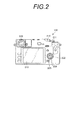
- the imaging apparatus 100 is a lens interchangeable camera.
- the imaging apparatus 100 includes a camera body 200 and an interchangeable lens 258 (shooting lens, focus ring 260), which is a zoom lens that is replaceably attached to the camera body 200.
- This is a digital camera with the flex mirror omitted.
- the camera body 200 is provided with a hybrid finder (registered trademark) 220.
- the hybrid viewfinder 220 here refers to a viewfinder in which, for example, an optical viewfinder (hereinafter referred to as “OVF”) and an electronic viewfinder (hereinafter referred to as “EVF”) are selectively used.
- OPF optical viewfinder
- EMF electronic viewfinder
- the camera body 200 and the interchangeable lens 258 are interchangeably mounted by combining a mount 256 provided in the camera body 200 and a mount 346 (see FIG. 3) on the interchangeable lens 258 side corresponding to the mount 256.
- a focus ring 260 is provided on the lens barrel of the interchangeable lens 258.
- the imaging apparatus 100 moves the focus lens in the direction of the optical axis in accordance with the rotation operation of the focus ring 260, and forms an image of subject light on an imaging element 20 (see FIG. 3) described later at a focus position corresponding to the subject distance. (Manual focusing).
- a front view of the camera body 200 is provided with an OVF viewfinder window 241 included in the hybrid viewfinder 220.
- a finder switching lever 214 is provided on the front surface of the camera body 200. When the viewfinder switching lever 214 is rotated in the direction of the arrow SW, it switches between an optical image that can be viewed with OVF and an electronic image (live view image) that can be viewed with EVF (described later).
- the OVF optical axis L2 is an optical axis different from the optical axis L1 of the interchangeable lens 258.
- a release switch 211 and a dial 212 for setting a shooting mode, a playback mode, and the like are mainly provided on the upper surface of the camera body 200.
- the release switch 211 detects a two-stage pressing operation: a state where the release switch 211 is pressed from the standby position to the intermediate position (half-pressed position) and a state where the release switch 211 is pressed to the final pressed position (full-pressed position) beyond the intermediate position. It is configured to be possible.
- “a state where the button is pressed from the standby position to the half-pressed position” is referred to as “half-pressed state”
- “a state where the button is pressed from the standby position to the fully-pressed position” is referred to as “full-pressed state”.
- the shooting control process described later is executed by pressing the release switch 211 halfway, and then exposure (shooting) is performed when the release switch 211 is fully pressed.
- an OVF viewfinder eyepiece 242 a display unit 213, a cross key 222, a MENU / OK key 224, and a BACK / DISP button 225 are provided on the back of the camera body 200.
- the cross key 222 functions as a multi-function key that outputs various command signals such as menu selection, zoom and frame advance.
- the MENU / OK key 224 has both a function as a menu button for instructing to display a menu on the screen of the display unit 213 and an function as an OK button for instructing confirmation and execution of selection contents. Key.
- the BACK / DISP button 225 is used to delete a desired object such as a selection item, cancel a designated content, or return to the previous operation state.
- the display unit 213 is realized by, for example, an LCD, and is used to display a live view image (through image) that is an example of a continuous frame image obtained by capturing a continuous frame in the shooting mode.
- the display unit 213 is also used to display a still image that is an example of a single frame image obtained by capturing a single frame when a still image shooting instruction is given.
- the display unit 213 is also used for displaying a playback image and a menu screen in the playback mode.
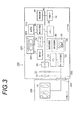
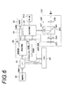
- the imaging device 100 is a digital camera that records captured still images and moving images, and the operation of the entire camera is a CPU (Central Processing Unit) 1 shown in FIG. 2 is centrally controlled.
- the imaging apparatus 100 includes an operation unit 14, an interface unit 24, a memory 26, and an encoder 34 in addition to the CPU 12.
- the imaging apparatus 100 also includes a display control unit 36, an eyepiece detection unit 37, and an external interface (I / F) 39, which are examples of display control means according to the present invention.
- the imaging apparatus 100 includes an image processing unit 28 that is an example of a generation unit and a parallax calculation unit according to the present invention.
- the CPU 12, the operation unit 14, the interface unit 24, the memory 26, the image processing unit 28, the encoder 34, the display control unit 36, the eyepiece detection unit 37, and the external interface (I / F) 39 are connected to each other via the bus 40.
- the memory 26 includes a non-volatile storage area (such as an EEPROM) that stores parameters, programs, and the like, and a volatile storage area (such as an SDRAM) that temporarily stores various information such as images.
- the CPU 12 performs focusing control by driving and controlling the focus adjustment motor so that the contrast value of the image obtained by imaging is maximized. Further, the CPU 12 calculates AE information that is a physical quantity indicating the brightness of an image obtained by imaging. When the release switch 211 is half-pressed, the CPU 12 derives the shutter speed and F value corresponding to the brightness of the image indicated by the AE information. Then, the exposure state is set by controlling each related part so that the derived shutter speed and F value are obtained.
- the operation unit 14 is a user interface operated by the operator when giving various instructions to the imaging apparatus 100. Various instructions received by the operation unit 14 are output as operation signals to the CPU 12, and the CPU 12 executes processing according to the operation signals input from the operation unit 14.
- the operation unit 14 includes a release switch 211, a dial 212, a display unit 213, a viewfinder switching lever 214, a cross key 222, a MENU / OK key 224, and a BACK / DISP button 225.
- the image light indicating the subject is received by the color image sensor (for example, a CMOS sensor) 20 via the photographing lens 16 including the focus lens that can be moved manually and the shutter 18.
- the image is formed on the surface.
- the signal charge accumulated in the image sensor 20 is sequentially read out as a digital signal corresponding to the signal charge (voltage) by a read signal applied from the device control unit 22.
- the imaging element 20 has a so-called electronic shutter function, and controls the charge accumulation time (shutter speed) of each photosensor according to the timing of the readout signal by using the electronic shutter function.
- the image sensor 20 according to the first embodiment is a CMOS image sensor, but is not limited thereto, and may be a CCD image sensor.
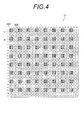
- the image sensor 20 is provided with a color filter 21 as shown in FIG.
- the color filter 21 includes a first filter G corresponding to G (green) that contributes most to obtain a luminance signal, and second filters R and B corresponding to R (red).
- a third filter B corresponding to (blue) is included.
- the imaging apparatus 100 has a phase difference AF function.
- the image sensor 20 according to the present embodiment includes a plurality of phase difference detection pixels that are used when the phase difference AF function is activated.
- the plurality of phase difference detection pixels are arranged in a predetermined pattern.
- the pixel for phase difference detection is either the first pixel L in which the left half in the horizontal direction is shielded or the second pixel R in which the right half in the horizontal direction is shielded.
- phase difference pixels when it is not necessary to distinguish between the first pixel L and the second pixel R, they are referred to as “phase difference pixels”.
- the first pixel L has a light shielding member 20A
- the second pixel R has a light shielding member 20B.
- the light shielding member 20A is provided on the front side (microlens M side) of the photodiode PD, and shields the left half of the light receiving surface.
- the light shielding member 20B is provided on the front side of the photodiode PD and shields the right half of the light receiving surface.
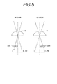
- the microlens M and the light shielding members 20A and 20B function as a pupil dividing unit, the first pixel L receives only the left side of the optical axis of the light beam passing through the exit pupil of the photographing lens 16, and the second pixel R is Only the right side of the optical axis of the light beam passing through the exit pupil of the photographing lens 16 is received. In this way, the light beam passing through the exit pupil is divided into left and right by the microlens M and the light shielding members 20A and 20B, which are pupil dividing portions, and enter the first pixel L and the second pixel R, respectively.
- the subject image corresponding to the left half of the light flux passing through the exit pupil of the photographing lens 16 and the subject image corresponding to the right half of the light flux are in focus (in focus).
- the portion forms an image at the same position on the image sensor 20.
- the front pin that is in focus before the subject or the rear pin that is in focus behind the subject is incident on a different position on the image sensor 20 (out of phase).
- the subject image corresponding to the left half light beam and the subject image corresponding to the right half light beam can be acquired as parallax images (left eye image and right eye image) having different parallaxes.
- the imaging apparatus 100 detects a phase shift amount based on the pixel value of the first pixel L and the pixel value of the second pixel R. Then, the adjustment of the focal position of the photographic lens 16 by a user operation is assisted by presenting the detected phase shift amount.
- the light shielding members 20A and 20B are referred to as “light shielding members” without reference numerals.
- the image sensor 20 is classified into a first pixel group, a second pixel group, and a third pixel group.
- the first pixel group refers to a plurality of first pixels L, for example.
- the second pixel group refers to a plurality of second pixels R, for example.
- the third pixel group refers to a plurality of normal pixels, for example.
- the “normal pixel” here refers to, for example, a pixel other than the phase difference pixel (for example, a pixel having no light shielding members 20A and 20B).
- the RAW image indicated by the image signal output from the first pixel group is referred to as a “first image”.
- the RAW image indicated by the image signal output from the second pixel group is referred to as a “second image”.
- the RAW image indicated by the image signal output from the third pixel group is referred to as a “third image”.
- Each pixel included in the first pixel group and the second pixel group is disposed at a position where the positions in the horizontal direction are aligned within one pixel between the first pixel group and the second pixel group. .
- each pixel included in the first pixel group and the second pixel group is disposed at a position where the positions in the vertical direction are aligned within the one pixel between the first pixel group and the second pixel group. ing.
- the first pixel L and the second pixel R are alternately arranged at intervals of a plurality of pixels (in this embodiment, two pixels) linearly in each of the horizontal direction and the vertical direction. Is arranged.
- the positions of the pixels included in the first and second pixel groups are positions that are aligned within one pixel in each of the horizontal direction and the vertical direction, but at least in the horizontal direction and the vertical direction.
- One of the positions may be within a predetermined number of pixels (for example, within 2 pixels).
- the position of each pixel included in the first and second pixel groups is set horizontally. It is preferable that the positions are aligned within one pixel in each of the direction and the vertical direction.
- the phase difference pixels are 2 ⁇ 2 pixels (for example, 3rd row, 3rd column, 3rd row, 4th column, 4th row, 3rd column, and 4th row, 4th from the upper left in front view of FIG. 4). It is provided for the pixels of the G filter in a square array corresponding to the pixels in the column). In the present embodiment, the pixel in the lower right corner of the front view in FIG. 4 among the 2 ⁇ 2 pixel G filter is assigned to the phase difference pixel.
- the light shielding member is provided for the pixel in the lower right corner of the 2 ⁇ 2 pixel G filter, and the phase difference pixel is spaced by a plurality of pixels in both the vertical direction and the horizontal direction.
- the phase difference pixel is spaced by a plurality of pixels in both the vertical direction and the horizontal direction.
- the interpolation accuracy in the case of interpolating the pixel values of the phase difference pixels from the pixel values of the normal pixels can be improved.
- the pixels included in the first to third pixel groups are arranged so that the normal pixels used for interpolation do not overlap between the phase difference pixels, further improvement in interpolation accuracy can be expected.
- the image sensor 20 outputs an image signal (digital signal indicating the pixel value of each first pixel) indicating the first image from the first pixel group, and outputs the image signal from the second pixel group.
- An image signal indicating a second image (a digital signal indicating a pixel value of each second pixel) is output.
- the imaging element 20 outputs an image signal indicating a third image (a digital signal indicating a pixel value of each normal pixel) from the third pixel group.
- the third image is a chromatic image, for example, a color image having the same color array as the normal pixel array.
- the image data indicating the first image, the second image, and the third image are temporarily stored in a volatile storage area in the memory 26 via the interface unit 24.
- the image processing unit 28 includes a normal processing unit 30.
- the normal processing unit 30 processes the R, G, and B signals corresponding to the third pixel group to generate a chromatic color normal image that is an example of the first display image.
- the image processing unit 28 includes a split image processing unit 32.
- the split image processing unit 32 processes the G signal corresponding to the first pixel group and the second pixel group to generate an achromatic split image that is an example of a second display image.
- the image processing unit 28 according to the present embodiment is realized by an ASIC (Application Specific Integrated Circuit) that is an integrated circuit in which circuits for realizing a plurality of functions related to image processing are combined into one.
- ASIC Application Specific Integrated Circuit
- the CPU 12 executes a shooting control processing program, which will be described later, and causes the split image processing unit 32 to generate a split image and controls the display unit 213 to display the generated split image.
- the hardware configuration of the image processing unit 28 is not limited to the ASIC, and may be another hardware configuration such as a computer including a programmable logic device, CPU, ROM, and RAM.
- the encoder 34 converts the input signal into a signal of another format and outputs it.
- the hybrid viewfinder 220 has an LCD 247 that displays an electronic image.
- the number of pixels in a predetermined direction on the LCD 247 (for example, the number of pixels in the horizontal direction, which is a parallax generation direction) is smaller than the number of pixels in the same direction on the display unit 213.
- the display control unit 36 is connected to the display unit 213 and the LCD 247, respectively, and an image is displayed on the LCD 247 or the display unit 213 by selectively controlling the LCD 247 and the display unit 213.
- the display unit 213 and the LCD 247 are referred to as “display devices” when it is not necessary to distinguish between them.
- the imaging apparatus 100 is configured to be able to switch between the manual focus mode and the autofocus mode described above using the dial 212.
- the display control unit 36 causes the display device to display a live view image obtained by combining the split images.
- the CPU 12 operates as a phase difference detection unit and an automatic focus adjustment unit.
- the phase difference detection unit detects a phase difference between the first image output from the first pixel group and the second image output from the second pixel group.
- the automatic focus adjustment unit controls the lens driving unit (not shown) from the device control unit 22 via the mounts 256 and 346 so that the defocus amount of the photographing lens 16 is zero based on the detected phase difference. Then, the photographing lens 16 is moved to the in-focus position.
- the above “defocus amount” refers to, for example, the amount of phase shift between the first image and the second image.
- the eyepiece detection unit 37 detects that the user has looked into the viewfinder eyepiece unit 242, and outputs the detection result to the CPU 12. Therefore, the CPU 12 can grasp whether or not the finder eyepiece unit 242 is used based on the detection result of the eyepiece detection unit 37.
- the external I / F 39 is connected to a communication network such as a LAN (Local Area Network) or the Internet, and controls transmission / reception of various information between the external device (for example, a printer) and the CPU 12 via the communication network. Therefore, when a printer is connected as an external device, the imaging apparatus 100 can output a captured still image to the printer for printing. Further, when a display is connected as an external device, the imaging apparatus 100 can output and display a captured still image or live view image on the display.
- a communication network such as a LAN (Local Area Network) or the Internet
- the normal processing unit 30 and the split image processing unit 32 each have a WB gain unit, a gamma correction unit, and a synchronization processing unit (not shown), and the original digital data temporarily stored in the memory 26.
- Each processing unit sequentially performs signal processing on the signal (RAW image). That is, the WB gain unit executes white balance (WB) by adjusting the gains of the R, G, and B signals.
- the gamma correction unit performs gamma correction on each of the R, G, and B signals that have been subjected to WB by the WB gain unit.
- the synchronization processing unit performs color interpolation processing corresponding to the arrangement of the color filters 21 of the image sensor 20, and generates synchronized R, G, B signals.
- the normal processing unit 30 and the split image processing unit 32 perform image processing on the RAW image in parallel every time a RAW image for one screen is acquired by the image sensor 20.
- the normal processing unit 30 receives the R, G, B RAW images from the interface unit 24 and performs the first processing on the pixels that are shielded from light by the phase difference image in the R, G, B pixels of the third pixel group. Are interpolated with peripheral pixels of the same color in the pixel group and the second pixel group (for example, adjacent G pixels).
- the normal processing unit 30 may use the image obtained by the interpolation as a normal image for display and a normal image for recording.
- the normal processing unit 30 outputs the generated image data of the normal image for recording to the encoder 34.
- the R, G, and B signals processed by the normal processing unit 30 are converted (encoded) into recording signals by the encoder 34 and recorded in the recording unit 42 (see FIG. 6).
- the normal processing unit 30 outputs the generated image data of the normal image for display to the display control unit 36.
- the term “for recording” and “for display” are used. Is referred to as a “normal image”.
- the image sensor 20 can change the exposure conditions (shutter speed by an electronic shutter as an example) of each of the first pixel group and the second pixel group, and thereby can simultaneously acquire images having different exposure conditions. . Therefore, the image processing unit 28 can generate an image with a wide dynamic range based on images with different exposure conditions. In addition, a plurality of images can be simultaneously acquired under the same exposure condition, and by adding these images, a high-sensitivity image with little noise can be generated, or a high-resolution image can be generated.
- the split image processing unit 32 extracts the G signal of the first pixel group and the second pixel group from the RAW image once stored in the memory 26, and the G of the first pixel group and the second pixel group. An achromatic split image is generated based on the signal.
- Each of the first pixel group and the second pixel group extracted from the RAW image is a pixel group including G filter pixels as described above. Therefore, the split image processing unit 32 can generate an achromatic left parallax image and an achromatic right parallax image based on the G signals of the first pixel group and the second pixel group.
- the above “achromatic left parallax image” is referred to as a “left eye image”
- the above “achromatic right parallax image” is referred to as a “right eye image”.
- the split image processing unit 32 combines the left-eye image based on the first image output from the first pixel group and the right-eye image based on the second image output from the second pixel group to split the image. Generate an image.
- the generated split image data is output to the display controller 36.
- the display control unit 36 records image data corresponding to the third pixel group input from the normal processing unit 30 and the split corresponding to the first and second pixel groups input from the split image processing unit 32. Display image data is generated based on the image data of the image. For example, the display control unit 36 displays the image input from the split image processing unit 32 in the display area of the normal image indicated by the recording image data corresponding to the third pixel group input from the normal processing unit 30. The split image indicated by the data is synthesized. Then, the image data obtained by the synthesis is output to the display device.
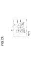
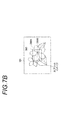
- the split image generated by the split image processing unit 32 is a multi-divided image obtained by combining a part of the left eye image and a part of the right eye image.
- Examples of the “multi-divided image” mentioned here include a split image 300 shown in FIGS. 7A and 7B.
- the split image 300 includes an upper half of the divided images obtained by dividing the left-eye image 300A into two in the front view vertical direction in FIGS. 7A and 7B, and a divided image obtained by dividing the right-eye image 300B in the same manner. It is an image obtained by combining the lower half divided image.
- the split image 300 is shifted in a predetermined direction (in this embodiment, left and right directions in front view in FIGS. 7A and 7B) by an amount corresponding to the in-focus state between the divided images of the left eye image 300A and the right eye image 300B. It is an image.
- the split image 300 when the split image 300 is combined with the normal image 301, the split image 300 is combined instead of a part of the normal image, but the combining method is not limited to this.
- a composition method in which the split image 300 is superimposed on the normal image 301 may be used.
- the composition method is a method of superimposing the split image 300 by appropriately adjusting the transmittance of a part of the normal image 301 corresponding to the region on which the split image 300 is superimposed.
- the normal image 301 and the split image 300 may be displayed in different layers. Thereby, the split image 300 can be displayed in the display area of the normal image in the live view image.
- the live view image is an image that shows a subject image when a subject image that is continuously photographed is displayed continuously on the screen of the display device.
- the hybrid finder 220 includes an OVF 240 and an EVF 248.
- the OVF 240 is an inverse Galileo finder having an objective lens 244 and an eyepiece 246, and the EVF 248 has an LCD 247, a prism 245, and an eyepiece 246.
- a liquid crystal shutter 243 is disposed in front of the objective lens 244, and the liquid crystal shutter 243 shields light so that an optical image does not enter the objective lens 244 when the EVF 248 is used.
- the prism 245 reflects an electronic image or various information displayed on the LCD 247 and guides it to the eyepiece 246, and combines the optical image and information (electronic image and various information) displayed on the LCD 247.
- an OVF mode in which an optical image can be visually recognized by the OVF 240 and an electronic image can be visually recognized by the EVF 248 each time it is rotated.
- the EVF mode is switched alternately.
- the display control unit 36 controls the liquid crystal shutter 243 to be in a non-light-shielded state so that the optical image can be viewed from the viewfinder eyepiece 242. Further, only the split image 300 is displayed on the LCD 247. Thereby, the finder image in which the split image 300 is superimposed on a part of the optical image can be displayed.
- the display control unit 36 controls the liquid crystal shutter 243 to be in a light shielding state so that only the electronic image displayed on the LCD 247 from the viewfinder eyepiece unit 242 can be visually recognized.
- image data equivalent to the image data obtained by combining the split image 300 output to the display unit 213 is input to the LCD 247. Accordingly, the display control unit 36 can display an electronic image in which the split image 300 is combined with a part of the normal image 301 in the same manner as the display unit 213.
- an image signal indicating each of the normal image 301 and the split image 300 is input to the display device.
- the display device displays the split image 300 indicated by the input image signal in the display area of the split image 300 having a rectangular shape at the center of the screen. Further, the display device displays the normal image 301 indicated by the input image signal in the outer peripheral area of the split image 300.
- the display device displays the normal image 301 indicated by the input image signal in the display area of the display device. Display in the whole area.
- the display device displays the split image 300 indicated by the input image signal in the display area. Let the area be a blank area.
- the imaging apparatus 100 stores in advance conversion information used when correcting distortion due to the photographing lens 16 in the memory 26.
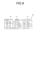
- the conversion information 320 according to the present embodiment includes focal length information 320 a indicating a plurality of predetermined focal length ranges.
- normal image conversion information 320b indicating conversion parameters for correcting distortion of the corresponding normal image 301 is associated with each focal length information 320a.
- split image conversion information 320c indicating conversion parameters for correcting distortion aberration of the split image 300 is associated with each of the focal length information 320a.
- the conversion parameter according to the present embodiment is a parameter in which a coordinate value before conversion and a coordinate value after conversion are associated with a plurality of predetermined coordinates in an image to be corrected.
- the imaging apparatus 100 corrects each distortion aberration of the normal image 301 and the split image 300 using the conversion information 320. That is, the imaging apparatus 100 according to the present embodiment corrects each distortion aberration of the normal image 301 and the split image 300 according to the focal length of the imaging lens 16.
- the focal length division width in the conversion information 320 becomes wider as the focal length becomes longer. This is because the distortion becomes smaller as the focal length becomes longer, that is, as the enlargement ratio becomes smaller.
- the imaging apparatus 100 corrects the distortion aberration of each of the normal image 301 and the split image 300 according to the focal length of the imaging lens 16, but is not limited thereto.
- the distortion aberration of each of the normal image 301 and the split image 300 may be corrected according to the aperture value.
- normal image conversion information 320b and split image conversion information 320c are associated with each of aperture value information indicating a plurality of predetermined aperture values.
- the conversion parameter of the split image 300 is a conversion parameter for converting the coordinates of each pixel in the split image 300 only in the orthogonal direction described later.
- the imaging apparatus 100 generates a split image 300 obtained by combining the left-eye image 300A and the right-eye image 300B and displays the split image 300 on the LCD 247. An imaging control process for performing control is performed.
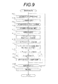
- FIG. 9 is a flowchart showing the flow of processing of the shooting control processing program executed by the CPU 12 when the imaging apparatus 100 is set to the manual focus mode and the release switch 211 is half-pressed.
- the program is stored in advance in a predetermined storage area of the memory 26.
- step S401 image data indicating the left eye image 300A based on the image signal output from the first pixel group, and image data indicating the right eye image 300B based on the image signal output from the second pixel group, Obtained via the interface unit 24.
- Each acquired image data is stored in a predetermined storage area of the memory 26 by the CPU 12.
- image data indicating the normal image 301 based on the image signal output from the third pixel group is acquired via the interface unit 24.
- the imaging apparatus 100 acquires image data indicating the normal image 301 from the third pixel group, but is not limited thereto, and is based on the image data acquired in steps S401 and S403. Image data indicating the normal image 301 may be generated.
- a method for generating image data indicating the normal image 301 at this time for example, a method in which the image data indicating the left-eye image 300A or the right-eye image 300B is directly used as image data indicating the normal image 301 is exemplified. Further, in the image data indicating the left eye image 300A or the right eye image 300B, an interpolation pixel is arranged between adjacent pixels, and the average value of the pixel values surrounding the interpolation pixel is used as the pixel value of the interpolation pixel.
- a method of generating image data indicating Further, the method of generating the normal image 301 may be a method of generating image data indicating the normal image 301 by combining image data indicating the left eye image 300A and the right eye image 300B.
- the focal length set at this time is acquired in the photographing lens 16, and the conversion parameter of the normal image 301 corresponding to the acquired focal length is acquired.
- the CPU 12 reads the normal image conversion information 230b associated with the focal length information 320a of the acquired focal length in the conversion information 320 from the memory 26, thereby converting the conversion parameters of the normal image 301 (hereinafter, “Norm image conversion parameter ”) is acquired.
- the distortion aberration of the normal image 301 is corrected based on the normal image conversion parameter.
- the CPU 12 converts the coordinates after conversion associated with the coordinate values before conversion. Convert to coordinate values.
- the CPU 12 uses the coordinate values of a plurality of coordinates close to the coordinates of the coordinate values before conversion of the normal image conversion parameters.
- the converted coordinates are linearly or nonlinearly interpolated using an arithmetic expression. Thereby, CPU12 obtains the coordinate after conversion of the coordinate used as conversion object.
- coordinates after conversion of coordinates to be converted are obtained by linear interpolation.
- the conversion information 320 is stored as a table in which the coordinate values before the conversion and the coordinate values after the conversion are associated with each other in all the coordinates in the normal image 301, and after the conversion of the coordinates to be converted using only the table. You may get the coordinates.
- the conversion information 320 may store an arithmetic expression for performing the above-described conversion, and the coordinates after conversion of the coordinates to be converted may be obtained using only the arithmetic expression.
- the normal image 301 acquired by the processing in step S403 has a shape distorted by the distortion.
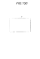
- the normal image 301 that has been corrected in step S409 has a rectangular shape as illustrated in FIG. 10B by correcting the distortion.
- control is performed to display the normal image 301 on which the distortion aberration is corrected on the display unit 213.
- the CPU 12 displays the normal image 301 on the display unit 213, but is not limited thereto, and may be displayed on the LCD 247.
- the CPU 12 displays the normal image 301 on the LCD 247 when the eyepiece detection unit 37 detects that the user has looked into the viewfinder eyepiece 242, and displays the normal image 301 otherwise. You may display on the part 213.
- the focal length set at this time is acquired, and the conversion parameter of the split image 300 corresponding to the acquired focal length is acquired.
- the CPU 12 reads the split image conversion information 230 c corresponding to the acquired focal length from the conversion information 320 from the memory 26. Thereby, the CPU 12 acquires the conversion parameter of the split image 300 (hereinafter referred to as “split image conversion parameter”).
- the split image processing unit 32 is controlled to generate a split image.
- the split image processing unit 32 reads information indicating the display area of the split image 300 on the display unit 213 (hereinafter referred to as “display area information”) from the memory 26.
- display area information information indicating the display area of the split image 300 on the display unit 213
- the range of the display area indicated by the predetermined coordinate system in the display area of each display device as the display area information in the memory 26 Is stored in advance.
- the split image processing unit 32 determines the division direction of each of the left eye image 300A and the right eye image 300B.
- information indicating the division direction (hereinafter referred to as “division direction information”) is stored in the memory 26 in advance, and the CPU 12 determines the division direction by reading the division direction information. .
- the split image processing unit 32 reads information indicating the number of divisions of each of the left eye image 300A and the right eye image 300B (hereinafter referred to as “division number information”) from the memory 26.
- the memory 26 stores the division number information in advance.
- the split image processing unit 32 generates the split image 300 based on information indicating each of the display area, the division direction, and the number of divisions obtained by the above processing.
- the distortion aberration of the split image 300 is corrected based on the acquired split image conversion parameter.
- the CPU 12 converts the coordinates of each pixel of the split image 300 using the split image conversion parameter in the same manner as in the case of the normal image 300 (step S409 above).
- the CPU 12 corrects the distortion aberration in the division direction with respect to the split image 300 and does not perform distortion aberration in a direction orthogonal to the division direction (hereinafter referred to as “orthogonal direction”).
- control is performed to display the split image 300 on which the distortion is corrected in the display area of the display unit 213.
- the CPU 12 superimposes and displays the image on the central portion of the normal image 301.
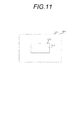
- the display unit 213 displays the normal image 301 in the entire display area, and the split image 300 in which the boundary 302 is a straight line is displayed in the center of the display area. .
- the distortion aberration decreases as the distance from the center of the photographing lens 16 increases. Therefore, when the split image 300 is corrected only for the distortion aberration with respect to the orthogonal direction, the straight line along the orthogonal direction at the central portion with respect to the division direction becomes a linear shape after the correction of the distortion aberration.
- the split image 300 generated by the process of step S415 has a shape distorted by the distortion as shown in FIG. 12A as an example.
- the split image 300 that has been corrected in step S417 is, as an example, as shown in FIG. 12B, the orthogonal direction (right and left when viewed from the front in FIG. Direction). Therefore, the boundary 302 between the left eye image 300A and the right eye image 300B is linear. Accordingly, the user can easily visually confirm the amount of shift between the left eye image 300A and the right eye image 300B in the split image 300.
- the CPU 12 erases the protrusion 304 that is included in the split image 300 and protrudes from the rectangular frame that has the largest area, and forms a rectangular shape. .
- each of the boundaries 302 in the split image 300 generated in step S415 is a curve or straight line having a different shape.
- the split image 300 corrected in step S417 is a straight line along the orthogonal direction in the vicinity of the center with respect to the division direction. Therefore, as an example, as shown in FIG. 12E, each of the boundaries 302 has a linear shape that is substantially parallel to each other. Note that the split image 300 shown in FIG. 12E is formed in a rectangular shape by erasing the protruding portion included in the split image 300 and protruding from the rectangular frame having the maximum area.
- step S421 it is determined whether or not a zoom operation has been performed by determining whether or not a zoom instruction input operation has been performed by operating the cross key 222. If the determination in step S421 is affirmative, the process proceeds to step S423. If the determination is negative, the process proceeds to step S425 described later. In step 423, the zoom magnification is changed according to the operation, and the focal position is moved.
- step S425 it is determined whether a shooting instruction has been input. At this time, the CPU 12 determines that a shooting instruction has been input when a full-press operation on the release switch 211 is detected. If a negative determination is made in step S425, the process returns to step S401 described above, whereas if an affirmative determination is made, the process proceeds to step S427.
- step S427 shooting processing for recording image data indicating the normal image 301 in the memory 26 is performed, and the shooting control processing program ends.
- photography process is a process currently performed generally, description here is abbreviate
- the conversion parameter is acquired according to the focal length of the photographing lens 16 while in the second embodiment, the conversion parameter is acquired according to the type of the interchangeable lens 258.
- the type of the interchangeable lens 258 according to the present invention include a single focus lens having a different focal length, a telecentric lens, and the like.
- the configuration of the imaging apparatus 100 according to the second embodiment is the same as that of the imaging apparatus 100 according to the first embodiment, and thus the description thereof is omitted here.
- the imaging apparatus 100 stores in advance conversion information used when correcting distortion due to the photographing lens 16 in the memory 26.
- the conversion information 322 according to the present embodiment includes lens information 322a indicating a plurality of predetermined lens types. Also, in the conversion information 322, normal image conversion information 322b indicating conversion parameters for correcting distortion of the corresponding normal image 301 is associated with each of the lens information 322a. Further, in the conversion information 322, split image conversion information 322c indicating conversion parameters for correcting distortion of the split image 300 is associated with each of the lens information 322a.
- the conversion parameters according to the second embodiment include coordinate values before conversion and coordinate values after conversion for a plurality of predetermined coordinates in an image to be corrected.
- the conversion parameter of the split image 300 is a conversion parameter for converting the coordinates of each pixel in the split image 300 only in the orthogonal direction.
- the imaging apparatus 100 corrects each distortion aberration of the normal image 301 and the split image 300 using the conversion information 322.
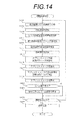
- FIG. 14 is a flowchart showing the flow of processing of the shooting control processing program executed by the CPU 12 of the imaging apparatus 100 at this time.
- the program is stored in advance in a predetermined area of the ROM of the memory 26.
- step S406 information indicating the type of the lens is acquired, and the process proceeds to step S407.
- the CPU 12 acquires an electrical signal indicating the lens type from the interchangeable lens 258 when the interchangeable lens 258 is coupled to the camera body 200.
- step S407 a normal image conversion parameter corresponding to the lens type indicated by the acquired lens type information is acquired.
- the CPU 12 reads the normal image conversion information 232b associated with the lens information 322a indicating the type of the lens in the conversion information 322, thereby acquiring the normal image conversion parameters.
- step S413 a split image conversion parameter corresponding to the lens type indicated by the acquired lens type information is acquired.
- the CPU 12 reads the split image conversion information 232c associated with the lens information 322a indicating the type of the lens in the conversion information 322, thereby acquiring the split image image conversion parameter.
- the imaging apparatus 100 is provided with a mounting portion (not shown) on which a conversion lens can be mounted, and the conversion lens may be mounted via the mounting portion.
- the conversion lens in this case is, for example, a wide conversion lens that shoots at a wider angle than the focal length of the photographic lens 16 or a tele conversion lens that shoots at a telephoto side of the bookstore distance of the photographic lens 16.
- These conversion lenses are attached to the imaging apparatus 100 by being attached to the side of the photographing lens 16 that is not mounted on the apparatus body, or mounted between the apparatus body or between the apparatus body and the photographing lens 16.
- Conversion parameters may be acquired according to the presence or absence of a conversion lens or the type of conversion lens when a conversion lens is coupled.
- the conversion parameter is acquired according to the type of the interchangeable lens 258, but the present invention is not limited to this, and the conversion parameter may be acquired according to the type of the conversion lens.
- conversion information used in correcting the distortion due to the photographing lens 16 is stored in the memory 26 in advance.
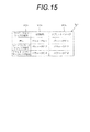
- the conversion information 324 includes lens information 324a indicating the presence / absence of a conversion lens or a plurality of predetermined types of conversion lenses when the conversion lens is coupled.
- normal image conversion information 324b indicating conversion parameters for correcting distortion aberration of the corresponding normal image 301 is associated with each conversion lens information 324a.
- each of the conversion lens information 324a is associated with split image conversion information 324c indicating conversion parameters for correcting distortion of the split image 300.
- the conversion parameter is a parameter in which coordinate values before conversion and coordinate values after conversion are associated with a plurality of predetermined coordinates in an image to be corrected.
- the conversion parameter of the split image 300 is a conversion parameter for converting the coordinates of each pixel in the split image 300 only in the orthogonal direction.
- the imaging apparatus 100 corrects each distortion aberration of the normal image 301 and the split image 300 using the conversion information 324. In addition, you may correct
- the imaging apparatus 100 according to the third embodiment will be described in detail with reference to the accompanying drawings.
- the conversion information 320, 322, and 324 includes the normal image conversion parameter and the split image conversion parameter.
- the split image conversion parameter is not included in the conversion information, and the split image conversion parameter is derived from the normal image conversion parameter.
- the configuration of the imaging apparatus 100 according to the third embodiment is the same as that of the imaging apparatus 100 according to the first embodiment, and a description thereof will be omitted here.
- the imaging apparatus 100 stores in advance conversion information used when correcting distortion due to the photographing lens 16 in the memory 26.
- the conversion information according to the present embodiment is information that does not include the split image conversion parameter in the conversion information 320 illustrated in FIG. 8, the conversion information 322 illustrated in FIG. 13, or the conversion information 324 illustrated in FIG. 15.
- FIG. 16 is a flowchart showing the flow of processing of the shooting control processing program executed by the CPU 12 of the imaging apparatus 100 at this time.
- the program is stored in advance in a predetermined area of the ROM of the memory 26.
- step S415 after performing the process of step S415, the process proceeds to step S418, the split image conversion parameter is derived, and the process proceeds to step S419.
- the CPU 12 derives the split image conversion parameter by using, as the split image conversion parameter, the conversion parameter related to the correction of the normal image conversion parameter in the conversion information with respect to the orthogonal direction. .
- a pair of the first pixel L and the second pixel R may be arranged for the two-pixel G filter.
- a pair of first and second pixels L and R adjacent in the row direction to a 2 ⁇ 2 pixel G filter may be arranged.
- a pair of first and second pixels L and R adjacent to each other in the column direction with respect to a 2 ⁇ 2 pixel G filter may be arranged.
- the positions of the first pixel L and the second pixel R are set at least in the column direction and the row direction between the first pixel group and the second pixel group. It is preferable to align one side within a predetermined number of pixels. 17 and 18, the first pixel L and the second pixel R, and the position in each of the column direction and the row direction between the first pixel group and the second pixel group are one pixel. An example is shown in which they are arranged at the same positions.
- the color filter 21 having the basic arrangement pattern C is exemplified, but the present invention is not limited to this.
- the arrangement of the primary colors (R filter, G filter, B filter) of the color filter may be a Bayer arrangement.
- phase difference pixels are arranged for the G filter.
- a phase difference pixel is arranged at the center of an array pattern G1 in which the four corners and the center of a 3 ⁇ 3 pixel square matrix are G filters. Further, the first pixel L and the second pixel R are alternately arranged with the G filter for one pixel being skipped in each of the row direction and the column direction (with the G filter for one pixel in between). Yes. Further, the first pixel L and the second pixel R are arranged at positions where the positions in the column direction and the row direction are aligned within one pixel between the first pixel group and the second pixel group. ing.
- an image based on the phase difference pixel at the center of the array pattern G1 can be interpolated using an image based on the normal pixels at the four corners of the array pattern G1, so that the interpolation accuracy is improved compared to the case without this configuration. Can be made.
- the positions of the array patterns G1 do not overlap each other. That is, the first pixel L and the second pixel R are interpolated with the third image by the pixels included in the third pixel group adjacent to the pixels included in the first and second pixel groups.
- the pixels included in the second image are arranged at positions that do not overlap in pixel units. Therefore, it is possible to avoid an image based on a phase difference pixel being interpolated with an image based on a normal pixel used in the interpolation of an image based on another phase difference pixel. Therefore, further improvement in interpolation accuracy can be expected.
- a phase difference pixel is arranged at the center of the array pattern G1 and at the lower right corner in the front view in the figure.
- the first pixel L and the second pixel R are alternately arranged by skipping the G filter for two pixels in each of the row direction and the column direction (with the G filter for two pixels in between). Yes.
- the first pixel L and the second pixel R are arranged at positions where the positions in the column direction and the row direction are aligned within one pixel between the first pixel group and the second pixel group.
- the first pixel L and the second pixel R can be adjacent to each other. Therefore, it is possible to suppress the occurrence of image shift due to factors other than focus shift.
- the interpolation accuracy can be improved.
- the positions of the array patterns G1 do not overlap each other. That is, the first pixel L and the second pixel R are interpolated with the third image by the pixels included in the third pixel group adjacent to the pixels included in the first and second pixel groups.
- the pixels included in the second image are arranged at positions that do not overlap in a pair of pixel units.
- the “pair of pixels” refers to, for example, a first pixel L and a second pixel R (a pair of phase difference pixels) included in each array pattern G1.
- the first pixel L is arranged at the center of the array pattern G1, and the second pixel R is arranged at the lower right corner in the front view in the figure.
- the first pixel L is disposed by skipping the G filters for two pixels in each of the row direction and the column direction
- the second pixel R is also a G filter for two pixels in each of the row direction and the column direction. It is arranged by skipping.
- the first pixel L and the second pixel R are arranged at positions where the positions in the column direction and the row direction are aligned within the two pixels between the first pixel group and the second pixel group.
- the first pixel L and the second pixel R can be adjacent to each other. Therefore, it is possible to suppress the occurrence of image shift due to factors other than focus shift.
- the positions of the array patterns G1 do not overlap with each other as in the example shown in FIG. Therefore, it is possible to avoid an image based on a phase difference pixel being interpolated with an image based on a normal pixel used in the interpolation of an image based on another phase difference pixel. Therefore, further improvement in interpolation accuracy can be expected.
- a color filter 21D shown in FIG. 22 schematically shows an example of the arrangement of primary colors (R filter, G filter, B filter) of the color filter 21D provided in the image sensor 20 and the arrangement of the light shielding members.
- the first to fourth row arrangements are repeatedly arranged in the column direction.
- the first row arrangement refers to an arrangement in which B filters and G filters are alternately arranged along the row direction.
- the second row arrangement refers to an arrangement obtained by shifting the first row arrangement by a half pitch (half pixel) in the row direction.
- the third row arrangement refers to an arrangement in which G filters and R filters are alternately arranged along the row direction.
- the fourth row arrangement refers to an arrangement obtained by shifting the third row arrangement by a half pitch in the row direction.
- the first row arrangement and the second row arrangement are adjacent to each other with a half pitch shift in the column direction.
- the second row arrangement and the third row arrangement are also adjacent to each other with a half-pitch shift in the column direction.
- the third row arrangement and the fourth row arrangement are adjacent to each other with a half-pitch shift in the column direction.
- the fourth row arrangement and the first row arrangement are also adjacent to each other with a half-pitch shift in the column direction. Accordingly, each of the first to fourth row arrays repeatedly appears every two pixels in the column direction.
- the first pixel L and the second pixel R are assigned to the third and fourth row arrays as shown in FIG. 22 as an example. That is, the first pixel L is assigned to the third row array, and the second pixel R is assigned to the fourth row array. Further, the first pixel L and the second pixel R are disposed adjacent to each other (minimum pitch) in pairs. In the example shown in FIG. 23, the first pixel L is assigned every six pixels in each of the row direction and the column direction, and the second pixel R is also six pixels in each of the row direction and the column direction. Assigned to each. Thereby, the phase difference between the first pixel group and the second pixel group is calculated with higher accuracy than in the case where the present configuration is not provided.
- G filters are assigned to the first pixel L and the second pixel R. Since the pixel provided with the G filter is more sensitive than the pixel provided with the filter of other colors, the interpolation accuracy can be increased. In addition, since the G filter has continuity compared to other color filters, pixels to which the G filter is assigned are more easily interpolated than pixels to which the other color filter is assigned.
- the split image divided in the vertical direction is exemplified.
- the present invention is not limited to this, and an image divided into a plurality of parts in the horizontal direction or the diagonal direction may be applied as the split image.
- the split image 66a shown in FIG. 23 is divided into odd lines and even lines by a plurality of boundary lines 63a parallel to the row direction.
- a line-like (eg, strip-like) phase difference image 66La generated based on the output signal outputted from the first pixel group is displayed on an odd line (even an even line is acceptable).
- a line-shaped (eg, strip-shaped) phase difference image 66Ra generated based on the output signal output from the second pixel group is displayed on even lines.
- the split image 66b shown in FIG. 24 is divided into two by a boundary line 63b (for example, a diagonal line of the split image 66b) having an inclination angle in the row direction.
- the phase difference image 66Lb generated based on the output signal output from the first pixel group is displayed in one area.
- the phase difference image 66Rb generated based on the output signal output from the second pixel group is displayed in the other region.
- the split image 66c shown in FIGS. 25A and 25B is divided by a grid-like boundary line 63c parallel to the row direction and the column direction, respectively.
- the phase difference image 66Lc generated based on the output signal output from the first pixel group is displayed in a checkered pattern (checker pattern).
- the phase difference image 66Rc generated based on the output signal output from the second pixel group is displayed in a checkered pattern.
- another focus confirmation image may be generated from the two phase difference images, and the focus confirmation image may be displayed.
- two phase difference images may be superimposed and displayed as a composite image. If the image is out of focus, the image may be displayed as a double image, and the image may be clearly displayed when the image is in focus.
- each process included in the image generation output process described in the first to third embodiments may be realized by a software configuration using a computer by executing a program. It may be realized by a hardware configuration. Further, it may be realized by a combination of a hardware configuration and a software configuration.
- the program may be stored in a predetermined storage area (for example, the memory 26) in advance. . It is not always necessary to store in the memory 26 from the beginning.
- a program is first stored in an arbitrary “portable storage medium” such as an SSD (Solid State Drive), a CD-ROM, a DVD disk, a magneto-optical disk, and an IC card that is connected to a computer. May be. Then, the computer may acquire the program from these portable storage media and execute it.
- each program may be stored in another computer or server device connected to the computer via the Internet, a LAN (Local Area Network), etc., and the computer may acquire and execute the program from these. Good.
- the imaging apparatus 100 is illustrated.
- a mobile terminal apparatus that is a modification of the imaging apparatus 100, for example, a mobile phone or a smartphone having a camera function, a PDA (Personal Digital Assistants) And portable game machines.
- a smartphone will be described as an example, and will be described in detail with reference to the drawings.
- FIG. 26 is a perspective view showing an example of the appearance of the smartphone 500.
- a smartphone 500 illustrated in FIG. 26 includes a flat housing 502, and a display input in which a display panel 521 as a display unit and an operation panel 522 as an input unit are integrated on one surface of the housing 502. Part 520.
- the housing 502 includes a speaker 531, a microphone 532, an operation unit 540, and a camera unit 541. Note that the configuration of the housing 502 is not limited thereto, and for example, a configuration in which the display unit and the input unit are independent, or a configuration having a folding structure or a slide structure may be employed.
- FIG. 27 is a block diagram illustrating an example of a configuration of the smartphone 500 illustrated in FIG.
- the main components of the smartphone 500 include a wireless communication unit 510, a display input unit 520, a call unit 530, an operation unit 540, a camera unit 541, a storage unit 550, and an external input / output. Part 560.
- a GPS (Global Positioning System) receiving unit 570, a motion sensor unit 580, a power supply unit 590, and a main control unit 501 are provided as a main function of the smartphone 500.
- a wireless communication function for performing mobile wireless communication via a base station device and a mobile communication network is provided as a main function of the smartphone 500.
- the wireless communication unit 510 performs wireless communication with a base station apparatus accommodated in the mobile communication network in accordance with an instruction from the main control unit 501. Using this wireless communication, transmission and reception of various file data such as audio data and image data, e-mail data, and reception of Web data and streaming data are performed.
- the display input unit 520 is a so-called touch panel, and includes a display panel 521 and an operation panel 522. For this reason, the display input unit 520 displays images (still images and moving images), character information, and the like visually by controlling the main control unit 501, and visually transmits information to the user, and performs user operations on the displayed information. To detect. Note that when viewing the generated 3D, the display panel 521 is preferably a 3D display panel.
- the display panel 521 uses an LCD, OELD (Organic Electro-Luminescence Display), or the like as a display device.
- the operation panel 522 is a device that is placed so that an image displayed on the display surface of the display panel 521 is visible and detects one or a plurality of coordinates operated by a user's finger or stylus. When such a device is operated by a user's finger or stylus, a detection signal generated due to the operation is output to the main control unit 501. Next, the main control unit 501 detects an operation position (coordinates) on the display panel 521 based on the received detection signal.
- the display panel 521 and the operation panel 522 of the smartphone 500 integrally form the display input unit 520, but the operation panel 522 is disposed so as to completely cover the display panel 521. ing.
- the operation panel 522 may have a function of detecting a user operation even in an area outside the display panel 521.
- the operation panel 522 includes a detection area (hereinafter referred to as a display area) for an overlapping portion that overlaps the display panel 521 and a detection area (hereinafter, a non-display area) for an outer edge portion that does not overlap the other display panel 521. May be included).
- the operation panel 522 may include two sensitive regions of the outer edge portion and the other inner portion. Further, the width of the outer edge portion is appropriately designed according to the size of the housing 502 and the like.
- examples of the position detection method employed in the operation panel 522 include a matrix switch method, a resistance film method, a surface acoustic wave method, an infrared method, an electromagnetic induction method, and a capacitance method. You can also
- the call unit 530 includes a speaker 531 and a microphone 532.
- the call unit 530 converts the user's voice input through the microphone 532 into voice data that can be processed by the main control unit 501 and outputs the voice data to the main control unit 501. Further, the call unit 530 decodes the audio data received by the wireless communication unit 510 or the external input / output unit 560 and outputs it from the speaker 531.
- the speaker 531 can be mounted on the same surface as the display input unit 520 and the microphone 532 can be mounted on the side surface of the housing 502.
- the operation unit 540 is a hardware key using a key switch or the like, and receives an instruction from the user.
- the operation unit 540 is mounted on the side surface of the housing 502 of the smartphone 500 and turns on when pressed with a finger or the like, and turns off when a finger is released with a restoring force such as a spring. It is a push button type switch.
- the storage unit 550 stores the control program and control data of the main control unit 501, application software, address data that associates the name and telephone number of the communication partner, and transmitted / received e-mail data.
- the storage unit 550 stores Web data downloaded by Web browsing and downloaded content data.
- the storage unit 550 temporarily stores streaming data and the like.
- the storage unit 550 includes an external storage unit 552 having an internal storage unit 551 built in the smartphone and a removable external memory slot.
- Each of the internal storage unit 551 and the external storage unit 552 constituting the storage unit 550 is realized using a storage medium such as a flash memory type or a hard disk type.
- Other storage media include multimedia card micro type, card type memory (for example, MicroSD (registered trademark) memory, etc.), RAM (Random Access Memory), ROM (Read Only Memory). ) Can be exemplified.
- the external input / output unit 560 serves as an interface with all external devices connected to the smartphone 500, and is used to connect directly or indirectly to other external devices through communication or the like or a network. is there. Examples of communication with other external devices include universal serial bus (USB), IEEE 1394, and the like. Examples of the network include the Internet, wireless LAN, Bluetooth (registered trademark), RFID (Radio Frequency Identification), and infrared communication (Infrared Data Association: IrDA) (registered trademark). Other examples of the network include UWB (Ultra Wideband) (registered trademark), ZigBee (registered trademark), and the like.
- Examples of the external device connected to the smartphone 500 include a memory card connected via a wired / wireless headset, a wired / wireless external charger, a wired / wireless data port, and a card socket.
- Other examples of external devices include SIM (Subscriber Examples include an Identity Module Card (UIM) / UIM (User Identity Module Card) card and an external audio / video device connected via an audio / video I / O (Input / Output) terminal.
- an external audio / video device that is wirelessly connected can be used.
- the external input / output unit may transmit data received from such an external device to each component inside the smartphone 500, or may allow data inside the smartphone 500 to be transmitted to the external device. it can.
- the GPS receiving unit 570 receives GPS signals transmitted from the GPS satellites ST1 to STn in accordance with instructions from the main control unit 501, performs positioning calculation processing based on the received GPS signals, and calculates the latitude of the smartphone 500 Detect the position consisting of longitude and altitude.
- the GPS reception unit 570 can acquire position information from the wireless communication unit 510 or the external input / output unit 560 (for example, a wireless LAN), the GPS reception unit 570 can also detect the position using the position information.
- the motion sensor unit 580 includes a triaxial acceleration sensor, for example, and detects the physical movement of the smartphone 500 in accordance with an instruction from the main control unit 501. By detecting the physical movement of the smartphone 500, the moving direction and acceleration of the smartphone 500 are detected. This detection result is output to the main control unit 501.
- the power supply unit 590 supplies power stored in a battery (not shown) to each unit of the smartphone 500 in accordance with an instruction from the main control unit 501.
- the main control unit 501 includes a microprocessor, operates according to a control program and control data stored in the storage unit 550, and controls each unit of the smartphone 500 in an integrated manner. Further, the main control unit 501 includes a mobile communication control function for controlling each unit of the communication system and an application processing function in order to perform voice communication and data communication through the wireless communication unit 510.
- the application processing function is realized by the main control unit 501 operating according to the application software stored in the storage unit 550.
- Application processing functions include, for example, an infrared communication function that controls the external input / output unit 560 to perform data communication with the opposite device, an e-mail function that transmits and receives e-mails, and a web browsing function that browses web pages. .
- the main control unit 501 has an image processing function such as displaying video on the display input unit 520 based on image data (still image data or moving image data) such as received data or downloaded streaming data.
- the image processing function is a function in which the main control unit 501 decodes the image data, performs image processing on the decoding result, and displays an image on the display input unit 520.
- the main control unit 501 executes display control for the display panel 521 and operation detection control for detecting a user operation through the operation unit 540 and the operation panel 522.
- the main control unit 501 By executing the display control, the main control unit 501 displays an icon for starting application software, a software key such as a scroll bar, or a window for creating an e-mail.
- a software key such as a scroll bar
- the scroll bar refers to a software key for accepting an instruction to move a display portion of an image, such as a large image that does not fit in the display area of the display panel 521.
- the main control unit 501 detects a user operation through the operation unit 540, or accepts an operation on the icon or an input of a character string in the input field of the window through the operation panel 522. Or, by executing the operation detection control, the main control unit 501 accepts a display image scroll request through a scroll bar.
- the main control unit 501 causes the operation position with respect to the operation panel 522 to overlap with the display panel 521 (display area) or other outer edge part (non-display area) that does not overlap with the display panel 521.
- a touch panel control function for controlling the sensitive area of the operation panel 522 and the display position of the software key is provided.
- the main control unit 501 can also detect a gesture operation on the operation panel 522 and execute a preset function according to the detected gesture operation.
- Gesture operation is not a conventional simple touch operation, but an operation that draws a trajectory with a finger or the like, designates a plurality of positions at the same time, or combines these to draw a trajectory for at least one of a plurality of positions. means.
- the camera unit 541 is a digital camera that captures an image using an image sensor such as a CMOS or a CCD, and has the same function as the image capturing apparatus 100 shown in FIG.
- the camera unit 541 can switch between a manual focus mode and an autofocus mode.
- the photographing lens 16 of the camera unit 541 can be focused by operating a focus icon button or the like displayed on the operation unit 540 or the display input unit 520.
- the manual focus mode the live view image obtained by combining the split images is displayed on the display panel 521 so that the in-focus state during the manual focus can be confirmed. Note that the hybrid finder 220 shown in FIG.
- the camera unit 541 converts image data obtained by imaging into compressed image data such as JPEG (Joint Photographic coding Experts Group) under the control of the main control unit 501.
- the converted image data can be recorded in the storage unit 550 or output through the external input / output unit 560 or the wireless communication unit 510.
- the camera unit 541 is mounted on the same surface as the display input unit 520, but the mounting position of the camera unit 541 is not limited to this, and the camera unit 541 may be mounted on the back surface of the display input unit 520.
- a plurality of camera units 541 may be mounted. Note that when a plurality of camera units 541 are mounted, the camera unit 541 used for imaging may be switched and imaged alone, or a plurality of camera units 541 may be used simultaneously for imaging. it can.
- the camera unit 541 can be used for various functions of the smartphone 500.
- an image acquired by the camera unit 541 can be displayed on the display panel 521, or the image of the camera unit 541 can be used as one of operation inputs of the operation panel 522.
- the GPS receiving unit 570 detects the position, the position can also be detected with reference to an image from the camera unit 541.
- the optical axis direction of the camera unit 541 of the smartphone 500 is determined without using the triaxial acceleration sensor or in combination with the triaxial acceleration sensor. It is also possible to determine the current usage environment.
- the image from the camera unit 541 can be used in the application software.
- various kinds of information can be added to still image or moving image data and recorded in the storage unit 550 or output through the external input / output unit 560 or the wireless communication unit 510.
- the “various information” herein include, for example, position information acquired by the GPS receiving unit 570 and image information of the still image or moving image, audio information acquired by the microphone 532 (sound text conversion by the main control unit or the like). May be text information).
- posture information acquired by the motion sensor unit 580 may be used.
- the image pickup device 20 having the first to third pixel groups is illustrated, but the present invention is not limited to this, and only the first pixel group and the second pixel group.
- An image sensor made of A digital camera having this type of image sensor generates a three-dimensional image (3D image) based on the first image output from the first pixel group and the second image output from the second pixel group. 2D images (2D images) can also be generated. In this case, the generation of the two-dimensional image is realized, for example, by performing an interpolation process between pixels of the same color in the first image and the second image. Moreover, you may employ
- the split image 300 is displayed in the display area of the normal image 301.
- the present invention is not limited to this, and the normal image 301 is displayed on the display device.
- the split image 300 may be displayed without displaying it.
- the split image 300 is displayed in a part of the display area of the display device.
- the present invention is not limited to this, and the split image 300 may be displayed in the entire display area of the display device.
- the present invention is not limited to a mode in which both the normal image 301 and the split image 300 are simultaneously displayed on the same screen of the display device.
- the display control unit 36 when the display instruction of the normal image 301 is canceled while the display of the split image 300 is instructed, the display control unit 36 does not display the normal image 301 on the display device, and the split image is displayed. Control for displaying 300 may be performed.
Landscapes
- Engineering & Computer Science (AREA)
- Multimedia (AREA)
- Signal Processing (AREA)
- Physics & Mathematics (AREA)
- General Physics & Mathematics (AREA)
- Optics & Photonics (AREA)
- Spectroscopy & Molecular Physics (AREA)
- Human Computer Interaction (AREA)
- Studio Devices (AREA)
- Automatic Focus Adjustment (AREA)
- Indication In Cameras, And Counting Of Exposures (AREA)
- Focusing (AREA)
- Image Processing (AREA)
Abstract
歪曲収差に対する補正に伴うスプリットイメージの視認性の低下を抑制することができる画像処理装置、撮像装置、プログラム及び画像処理方法を提供する。撮像レンズにおける第1及び第2の領域を通過した被写体像が瞳分割されてそれぞれ結像される第1及び第2の画素群を有する撮像素子から出力された画像信号に基づいてライブビュー画像として使用する第1の表示用画像及び合焦確認に使用する第2の表示用画像を生成し(S403、S415)、第1の表示用画像の歪曲収差の補正を行い(S403、S411)、第2の表示用画像の分割方向に対する歪曲収差を補正し、かつ分割方向と直交する方向に対する歪曲収差を行わない(S409、S417)。
Description
本発明は、画像処理装置、撮像装置、プログラム及び画像処理方法に係り、特に、被写体像の合焦状態を確認するための画像を生成して表示する画像処理装置、撮像装置、プログラム、及び画像処理方法に関する。
従来、デジタルカメラやカメラ付きの携帯電話機等の撮像装置において、手動で焦点調整を行う作業を容易にするために、スプリットイメージをライブビュー画像(所謂スルー画像)内に表示する技術が用いられるようになってきた。なお、スプリットイメージとは、被写体像における所定領域に対応する左目画像の一部と右目画像の一部とを合成した画像である。このスプリットイメージにおいては、合焦状態に応じて、左目画像と右目画像との間で視差発生方向に対するずれが発生する。この技術を利用し、ユーザは、スプリットイメージにおける左目画像と右目画像とのずれを視認することで合焦状態を確認する。
これに関する技術として、特許文献1には、瞳分割された撮像用の画素から得られる信号を用いてスプリットイメージを生成する撮像装置が開示されている。この撮像装置は、スプリットイメージを表示する際、瞳分割されない撮像用の画素から得られる信号の色情報を左目画像と右目画像と付加し、スプリットイメージを有彩色で表示する。
一方、撮像レンズを介して撮像素子に結像される被写体像には撮像レンズに起因する歪曲収差が発生するため、従来の撮像装置において、この歪曲収差を補正する処理が行われている。
しかしながら、通常の撮像用の画素から得られる信号に対して、上記歪曲収差の補正を行うと、自動合焦制御における焦点検出の精度が低下してしまう、という問題が発生していた。
そこで、特許文献2には、上記歪曲収差の補正を行った場合でも、自動合焦制御における焦点検出の精度の低下を抑制することができる撮像装置が開示されている。この撮像装置は、通常の撮像用の画素から得られる信号、及び自動合焦制御用の画素から得られる信号に対して、各々別個に上記歪曲収差の補正を行うことにより、焦点検出の精度の低下を抑制している。
ところで、撮像装置においてスプリットイメージを表示させる場合、通常画像の場合と同様に、スプリットイメージにも上記歪曲収差が発生する。
そこで、スプリットイメージにおける上記歪曲収差の補正を行うために、上記特許文献1及び特許文献2に開示されている技術を応用することが考えられる。すなわち、通常の撮像用の画素から得られる信号、及びスプリットイメージ用の画素から得られる信号に対して、各々別個に上記歪曲収差の補正を行うことが考えられる。
一方、スプリットイメージにおける右目画像及び左目画像のずれ量をユーザが目視で確認するためには、右目画像と左目画像との境界が直線となっていることが視認性の面で望ましい。そのため、スプリットイメージの右目画像と左目画像とを合成する際には上記境界が直線となるように合成される。しかしながら、上記特許文献1及び特許文献2に開示されている技術を応用した場合には、上記境界が上記歪曲収差の量に応じて歪んでしまい、スプリットイメージの視認性が低下してしまう、という問題点があった。
本発明は上記問題点に鑑みてなされたものであり、歪曲収差に対する補正に伴う合焦確認画像(スプリットイメージ)の視認性の低下を抑制することができる画像処理装置、撮像装置、プログラム及び画像処理方法を提供することを目的とする。
上記目的を達成するために、本発明に係る画像処理装置は、撮像レンズにおける第1及び第2の領域を通過した被写体像が瞳分割されてそれぞれ結像される第1及び第2の画素群を有する撮像素子から出力された画像信号に基づいて第1の表示用画像を生成し、かつ上記第1及び第2の画素群から出力された画像信号に基づく第1及び第2の画像に基づいて、上記第1の画像を予め定められた分割方向に分割して得られた複数の分割画像の一部の第1の分割画像に、上記第2の画像を上記分割方向に分割して得られた複数の分割画像の上記第1の分割画像に対応する分割領域を除く第2の分割画像を配置した合焦確認に使用する第2の表示用画像を生成する生成部と、画像を表示する表示部と、上記表示部に対して上記生成部により生成された上記第1の表示用画像を表示し、かつ上記第1の表示用画像の表示領域内に上記生成部により生成された上記第2の表示用画像を表示する制御を行う表示制御部と、上記撮像レンズによる上記第1の表示用画像の歪曲収差の補正を行い、上記第2の表示用画像の上記分割方向に対する歪曲収差を補正し、かつ上記分割方向と直交する直交方向に対する歪曲収差を行わない補正部とを備えている。
本発明に係る画像処理装置によれば、生成部により、撮像レンズにおける第1及び第2の領域を通過した被写体像が瞳分割されてそれぞれ結像される第1及び第2の画素群を有する撮像素子から出力された画像信号に基づいて第1の表示用画像が生成される。
また、本発明では、生成部により、上記第1及び第2の画素群から出力された画像信号に基づく第1及び第2の画像に基づいて、上記第1の画像を予め定められた分割方向に分割して得られた複数の分割画像の一部の第1の分割画像に、上記第2の画像を上記分割方向に分割して得られた複数の分割画像の上記第1の分割画像に対応する分割領域を除く第2の分割画像を配置した合焦確認に使用する第2の表示用画像が生成される。
更に、本発明では、表示制御部により、上記表示部に対して上記生成部により生成された上記第1の表示用画像を表示し、かつ上記第1の表示用画像の表示領域内に上記生成部により生成された上記第2の表示用画像を表示する制御が行われる。
ここで、本発明では、補正部により、上記撮像レンズによる上記第1の表示用画像の歪曲収差の補正が行われ、上記第2の表示用画像の上記分割方向に対する歪曲収差が補正され、かつ上記分割方向と直交する直交方向に対する歪曲収差が行われない。
このように、本発明に係る画像処理装置は、第2の表示用画像(スプリットイメージ)の上記直交方向に対する歪曲収差を、第1の表示用画像(通常画像)と同様に補正する。これにより、第2の表示用画像と通常画像との間に上記直交方向に対するずれが生じることが防止される結果、歪曲収差に対する補正に伴う第2の表示用画像の視認性の低下を抑制することができる。
また、上記目的を達成するために、本発明の第2のアスペクトに係る画像処理装置は、撮像レンズにおける第1及び第2の領域を通過した被写体像が瞳分割されてそれぞれ結像される第1及び第2の画素群を有する撮像素子から出力された画像信号に基づいて第1の表示用画像を生成し、かつ上記第1及び第2の画素群から出力された画像信号に基づく第1及び第2の画像に基づいて、上記第1の画像を予め定められた分割方向に分割して得られた複数の分割画像の一部の第1の分割画像に、上記第2の画像を上記分割方向に分割して得られた複数の分割画像の上記第1の分割画像に対応する分割領域を除く第2の分割画像を配置した合焦確認に使用する第2の表示用画像を生成する生成部と、画像を表示する表示部と、上記生成部により生成された上記第1の表示用画像の上記表示部による表示を抑止し、かつ、上記表示部に対して、上記生成部により生成された上記第2の表示用画像を表示させる制御を行う表示制御部と、上記撮像レンズによる上記第1の表示用画像の歪曲収差の補正を行い、上記第2の表示用画像の上記分割方向に対する歪曲収差を補正し、かつ上記分割方向と直交する直交方向に対する歪曲収差を行わない補正部とを備えている。
本発明に係る画像処理装置によれば、生成部により、撮像レンズにおける第1及び第2の領域を通過した被写体像が瞳分割されてそれぞれ結像される第1及び第2の画素群を有する撮像素子から出力された画像信号に基づいて第1の表示用画像が生成される。
また、本発明では、生成部により、上記第1及び第2の画素群から出力された画像信号に基づく第1及び第2の画像に基づいて、上記第1の画像を予め定められた分割方向に分割して得られた複数の分割画像の一部の第1の分割画像に、上記第2の画像を上記分割方向に分割して得られた複数の分割画像の上記第1の分割画像に対応する分割領域を除く第2の分割画像を配置した合焦確認に使用する第2の表示用画像が生成される。
更に、本発明の第2のアスペクトに係る画像処理装置では、表示制御部により、上記生成部により生成された上記第1の表示用画像の上記表示部による表示を抑止し、かつ、上記表示部に対して、上記生成部により生成された上記第2の表示用画像を表示させる制御が行われる。
ここで、本発明では、補正部により、上記撮像レンズによる上記第1の表示用画像の歪曲収差の補正が行われ、上記第2の表示用画像の上記分割方向に対する歪曲収差が補正され、かつ上記分割方向と直交する直交方向に対する歪曲収差が行われない。
このように、本発明に係る画像処理装置は、第2の表示用画像の上記直交方向に対する歪曲収差を、第1の表示用画像と同様に補正する。これにより、第2の表示用画像と通常画像との間に上記直交方向に対するずれが生じることが防止される結果、歪曲収差に対する補正に伴う第2の表示用画像の視認性の低下を抑制することができる。
なお、本発明に係る画像処理装置において、上記撮像レンズはズームレンズであり、上記補正部は、上記ズームレンズによる焦点距離に応じて、上記歪曲収差の補正を行うようにしても良い。これにより、撮像レンズがズームレンズであっても、適切に歪曲収差に対する補正を行うことができる。
また、本発明に係る画像処理装置において、前記補正部は、前記撮像レンズの絞り値に応じて、前記歪曲収差の補正を行うようにしても良い。これにより、絞り値が変更されても、適切に歪曲収差に対する補正を行うことができる。
また、本発明に係る画像処理装置において、複数の上記撮像レンズの何れか1つを装置本体に交換可能に装着させる装着部と、上記装着部により装着された上記撮像レンズの種類を示す情報を取得する取得部とを更に備え、上記補正部は、上記取得部により取得された情報によって示される上記撮像レンズの種類に応じて、上記歪曲収差の補正を行うようにしても良い。これにより、撮像レンズ交換された場合であっても、適切に歪曲収差に対する補正を行うことができる。
また、本発明に係る画像処理装置において、予め定められた複数の種類から何れか1つの種類のコンバージョンレンズを装置本体に装着させる第2装着部と、上記第2装着部により装着された上記コンバージョンレンズの種類を示す情報を取得する第2取得部とを更に備え、上記補正部は、上記第2取得部により取得された情報によって示される上記コンバーションレンズの種類に応じて、上記歪曲収差の補正を行うようにしても良い。これにより、コンバージョンレンズが装着された場合であっても、適切に歪曲収差に対する補正を行うことができる。
また、本発明に係る画像処理装置において、予め定められた複数の種類から何れか1つの種類のコンバージョンレンズを、交換可能に装着された上記撮像レンズと装置本体との間、または交換可能に装着された上記撮像レンズの被写体側に装着させる第3装着部と、上記第3装着部により装着された上記コンバージョンレンズの種類を示す情報を取得する第2取得部とを更に備え、上記補正部は、上記第2取得部により取得された情報によって示される上記コンバーションレンズの種類に応じて、上記歪曲収差の補正を行うようにしても良い。これにより、コンバージョンレンズが装着された場合であっても、適切に歪曲収差に対する補正を行うことができる。
また、本発明に係る画像処理装置において、上記歪曲収差を補正するための座標変換に関する変換情報が予め記憶された記憶部を更に備え、上記補正部は、上記記憶部に記憶された上記変換情報に基づき、上記歪曲収差の補正を行うようにしても良い。これにより、予め記憶されている変換情報を用いて簡単に歪曲収差に対する補正を行うことができる。
また、本発明に係る画像処理装置において、上記第1の表示用画像の歪曲収差を補正するための座標変換に関する変換情報が予め記憶された記憶部と、上記記憶部に記憶された上記変換情報から上記第2の表示用画像の歪曲収差を補正するための座標変換に関する第2変換情報を導出する導出部とを更に備え、上記補正部は、上記記憶部に記憶された上記変換情報及び上記導出手段により導出された第2変換情報に基づき、上記歪曲収差の補正を行ようにしても良い。これにより、第2の表示用画像の歪曲収差を補正するための情報を予め記憶させる必要がなくなるため、記憶部の記憶容量を低減させることができる。
また、本発明に係る画像処理装置において、上記変換情報は、複数の画素について上記歪曲収差の補正前の座標と補正後の座標とが各々関連付けられた座標変換テーブルを示す情報、及び上記補正前の座標を上記補正後の座標に変換する演算式の少なくとも一方であるものとしても良い。これにより、変換情報として座標変換テーブルを用いた場合には。演算式を用いる場合と比較して、高速に歪曲収差の補正を行うことができ、変換情報として演算式を用いた場合には、座標変換テーブルを用いる場合と比較して、記憶部の記憶容量を低減させることができる。
また、本発明に係る画像処理装置において、上記表示制御部は、上記第2の表示用画像を、上記第1の表示用画像の上記分割方向に対する中央部に表示する制御を行うようにしても良い。これにより、撮像レンズにおいて歪曲収差が最小となる中央部に第2の表示用画像を表示させることができる結果、第2の表示用画像における第1の画像及び第2の画像の境界を直線とする、または直線に近付けることができる。
一方、上記目的を達成するために、本発明に記載の撮像装置は、本発明に係る画像処理装置と、上記撮像レンズと、上記撮像素子と、を備えている。
従って、本発明に係る撮像装置によれば、本発明に係る画像処理装置と同様に作用するので、本発明に係る画像処理装置と同様に、歪曲収差に対する補正に伴う第2の表示用画像の視認性の低下を抑制することができる。
また、上記目的を達成するために、本発明に係るプログラムは、コンピュータを、撮像レンズにおける第1及び第2の領域を通過した被写体像が瞳分割されてそれぞれ結像される第1及び第2の画素群を有する撮像素子から出力された画像信号に基づいて第1の表示用画像を生成し、かつ上記第1及び第2の画素群から出力された画像信号に基づく第1及び第2の画像に基づいて、上記第1の画像を予め定められた分割方向に分割して得られた複数の分割画像の一部の第1の分割画像、及び上記第2の画像を上記分割方向に分割して得られた複数の分割画像の上記第1の分割画像に対応する分割領域を除く第2の分割画像を配置した合焦確認に使用する第2の表示用画像を生成する生成部と、画像を表示する表示部に対して上記生成部により生成された上記第1の表示用画像を表示し、かつ上記第1の表示用画像の表示領域内に上記生成部により生成された上記第2の表示用画像を表示する制御を行う表示制御部と、上記撮像レンズによる上記第1の表示用画像の歪曲収差の補正を行い、上記第2の表示用画像の上記分割方向に対する歪曲収差を補正し、かつ上記分割方向と直交する直交方向に対する歪曲収差を行わない補正部と、として機能させる。
従って、本発明に係るプログラムによれば、コンピュータを本発明に係る画像処理装置と同様に作用させるので、本発明に係る画像処理装置と同様に、歪曲収差に対する補正に伴う第2の表示用画像の視認性の低下を抑制することができる。
更に、上記目的を達成するために、本発明に係る画像処理方法は、撮像レンズにおける第1及び第2の領域を通過した被写体像が瞳分割されてそれぞれ結像される第1及び第2の画素群を有する撮像素子から出力された画像信号に基づいて第1の表示用画像を生成し、かつ上記第1及び第2の画素群から出力された画像信号に基づく第1及び第2の画像に基づいて、上記第1の画像を予め定められた分割方向に分割して得られた複数の分割画像の一部の第1の分割画像、及び上記第2の画像を上記分割方向に分割して得られた複数の分割画像の上記第1の分割画像に対応する分割領域を除く第2の分割画像を配置した合焦確認に使用する第2の表示用画像を生成する生成ステップと、画像を表示する表示部に対して上記生成ステップにより生成された上記第1の表示用画像を表示し、かつ上記第1の表示用画像の表示領域内に上記生成ステップにより生成された上記第2の表示用画像を表示する制御を行う表示制御ステップと上記撮像レンズによる上記第1の表示用画像の歪曲収差の補正を行い、上記第2の表示用画像の上記分割方向に対する歪曲収差を補正し、かつ上記分割方向と直交する直交方向に対する歪曲収差を行わない補正ステップと、を有している。
従って、本発明に係る画像処理方法によれば、本発明に係る画像処理装置と同様に作用するので、本発明に係る画像処理装置と同様に、歪曲収差に対する補正に伴う第2の表示用画像の視認性の低下を抑制することができる。
本発明によれば、歪曲収差に対する補正に伴う合焦確認画像(スプリットイメージ)の視認性の低下を抑制することができる、という効果を奏する。
以下、添付図面に従って本発明に係る撮像装置の実施の形態の一例について説明する。
[第1実施形態]
本実施形態に係る撮像装置100は、レンズ交換式カメラである。また、撮像装置100は、図1に示すように、カメラ本体200と、カメラ本体200に交換可能に装着されるズームレンズである交換レンズ258(撮影レンズ、フォーカスリング260)と、を含み、レフレックスミラーが省略されたデジタルカメラである。また、カメラ本体200には、ハイブリッドファインダー(登録商標)220が設けられている。ここで言うハイブリッドファインダー220とは、例えば光学ビューファインダー(以下、「OVF」という)及び電子ビューファインダー(以下、「EVF」という)が選択的に使用されるファインダーを指す。
本実施形態に係る撮像装置100は、レンズ交換式カメラである。また、撮像装置100は、図1に示すように、カメラ本体200と、カメラ本体200に交換可能に装着されるズームレンズである交換レンズ258(撮影レンズ、フォーカスリング260)と、を含み、レフレックスミラーが省略されたデジタルカメラである。また、カメラ本体200には、ハイブリッドファインダー(登録商標)220が設けられている。ここで言うハイブリッドファインダー220とは、例えば光学ビューファインダー(以下、「OVF」という)及び電子ビューファインダー(以下、「EVF」という)が選択的に使用されるファインダーを指す。
カメラ本体200と交換レンズ258とは、カメラ本体200に備えられたマウント256と、マウント256に対応する交換レンズ258側のマウント346(図3参照)とが結合されることにより交換可能に装着される。また、交換レンズ258の鏡筒にはフォーカスリング260が設けられている。撮像装置100は、フォーカスリング260の回転操作に伴ってフォーカスレンズを光軸方向に移動させ、被写体距離に応じた合焦位置で後述の撮像素子20(図3参照)に被写体光を結像させる(マニュアルフォーカシング)ことができる。
カメラ本体200の前面には、ハイブリッドファインダー220に含まれるOVFのファインダー窓241が設けられている。また、カメラ本体200の前面には、ファインダー切替えレバー214が設けられている。ファインダー切替えレバー214を矢印SW方向に回動させると、OVFで視認可能な光学像とEVFで視認可能な電子像(ライブビュー画像)との間で切り換わるようになっている(後述)。なお、OVFの光軸L2は、交換レンズ258の光軸L1とは異なる光軸である。また、カメラ本体200の上面には、主としてレリーズスイッチ211及び撮影モードや再生モード等の設定用のダイヤル212が設けられている。
レリーズスイッチ211は、待機位置から中間位置(半押し位置)まで押下される状態と、中間位置を超えた最終押下位置(全押し位置)まで押下される状態と、の2段階の押圧操作が検出可能に構成されている。なお、以下では、「待機位置から半押し位置まで押下される状態」を「半押し状態」といい、「待機位置から全押し位置まで押下される状態」を「全押し状態」という。本第1実施形態に係る撮像装置100では、レリーズスイッチ211を半押し状態にすることにより後述する撮影制御処理が実行され、その後、引き続き全押し状態にすると露光(撮影)が行われる。
図2に示すように、カメラ本体200の背面には、OVFのファインダー接眼部242、表示部213、十字キー222、MENU/OKキー224、BACK/DISPボタン225が設けられている。
十字キー222は、メニューの選択、ズームやコマ送り等の各種の指令信号を出力するマルチファンクションのキーとして機能する。MENU/OKキー224は、表示部213の画面上にメニューを表示させる指令を行うためのメニューボタンとしての機能と、選択内容の確定及び実行などを指令するOKボタンとしての機能とを兼備した操作キーである。BACK/DISPボタン225は、選択項目など所望の対象の消去や指定内容の取消、あるいは1つ前の操作状態に戻すときなどに使用される。
表示部213は、例えばLCDにより実現され、撮影モード時に連続フレームで撮像されて得られた連続フレーム画像の一例であるライブビュー画像(スルー画像)の表示に用いられる。また、表示部213は、静止画撮影の指示が与えられた場合に単一フレームで撮像されて得られた単一フレーム画像の一例である静止画像の表示にも用いられる。更に、表示部213は、再生モード時の再生画像の表示やメニュー画面等の表示にも用いられる。
撮像装置100は、撮影した静止画像や動画像を記録するデジタルカメラであり、カメラ全体の動作は、図3に示されるCPU(Central Processing Unit:中央処理装置)1
2によって統括制御されている。同図に示すように、撮像装置100は、CPU12の他に、操作部14、インタフェース部24、メモリ26及びエンコーダ34を含む。また、撮像装置100は、本発明に係る表示制御手段の一例である表示制御部36、接眼検出部37及び外部インタフェース(I/F)39を含む。また、撮像装置100は、本発明に係る生成手段及び視差算出手段の一例である画像処理部28を含む。
2によって統括制御されている。同図に示すように、撮像装置100は、CPU12の他に、操作部14、インタフェース部24、メモリ26及びエンコーダ34を含む。また、撮像装置100は、本発明に係る表示制御手段の一例である表示制御部36、接眼検出部37及び外部インタフェース(I/F)39を含む。また、撮像装置100は、本発明に係る生成手段及び視差算出手段の一例である画像処理部28を含む。
CPU12、操作部14、インタフェース部24、メモリ26、画像処理部28、エンコーダ34、表示制御部36、接眼検出部37及び外部インタフェース(I/F)39は、バス40を介して相互に接続されている。なお、メモリ26は、パラメータやプログラムなどが記憶された不揮発性の記憶領域(一例としてEEPROMなど)と画像などの各種情報が一時的に記憶される揮発性の記憶領域(一例としてSDRAMなど)とを有する。
なお、本第1実施形態に係る撮像装置100では、CPU12が、撮像によって得られた画像のコントラスト値が最大となるように焦点調整モータを駆動制御することによって合焦制御を行う。また、CPU12は、撮像によって得られた画像の明るさを示す物理量であるAE情報を算出する。CPU12は、レリーズスイッチ211が半押し状態とされたときには、AE情報により示される画像の明るさに応じたシャッタースピード及びF値を導出する。そして、導出したシャッタースピード及びF値となるように関係各部を制御することによって露出状態の設定を行う。
操作部14は、撮像装置100に対して各種指示を与える際に操作者によって操作されるユーザインタフェースである。操作部14によって受け付けられた各種指示は操作信号としてCPU12に出力され、CPU12は、操作部14から入力された操作信号に応じた処理を実行する。
操作部14は、レリーズスイッチ211、ダイヤル212、表示部213、ファインダー切替えレバー214、十字キー222、MENU/OKキー224及びBACK/DISPボタン225を含む。
ダイヤル212により撮影モードが設定されると、被写体を示す画像光は、手動操作により移動可能なフォーカスレンズを含む撮影レンズ16及びシャッタ18を介してカラーの撮像素子(一例としてCMOSセンサ)20の受光面に結像される。撮像素子20に蓄積された信号電荷は、デバイス制御部22から加えられる読出し信号によって信号電荷(電圧)に応じたデジタル信号として順次読み出される。撮像素子20は、いわゆる電子シャッタ機能を有しており、電子シャッタ機能を働かせることで、読出し信号のタイミングによって各フォトセンサの電荷蓄積時間(シャッタスピード)を制御する。なお、本第1実施形態に係る撮像素子20は、CMOS型のイメージセンサであるが、これに限らず、CCDイメージセンサでもよい。
撮像素子20には一例として図4に示すようなカラーフィルタ21が設けられている。一例として図4に示すように、カラーフィルタ21は、輝度信号を得るために最も寄与するG(緑)に対応する第1のフィルタG、R(赤)に対応する第2のフィルタR及びB(青)に対応する第3のフィルタBを含む。
また、本実施形態に係る撮像装置100は、位相差AF機能を有する。更に、本実施形態に係る撮像素子20は、位相差AF機能を働かせた場合に用いられる複数の位相差検出用の画素を含む。この複数の位相差検出用の画素は予め定めたパターンで配置されている。
位相差検出用の画素は、水平方向の左半分が遮光された第1の画素L及び水平方向の右半分が遮光された第2の画素Rの何れかである。なお、以下では、第1の画素L及び第2の画素Rを区別して説明する必要がない場合は「位相差画素」と称する。
一例として図5に示すように、第1の画素Lは遮光部材20Aを有し、第2の画素Rは遮光部材20Bを有する。遮光部材20Aは、フォトダイオードPDの前面側(マイクロレンズM側)に設けられており、受光面の左半分を遮光する。一方、遮光部材20Bは、フォトダイオードPDの前面側に設けられており、受光面の右半分を遮光する。
マイクロレンズM及び遮光部材20A,20Bは瞳分割部として機能し、第1の画素Lは、撮影レンズ16の射出瞳を通過する光束の光軸の左側のみを受光し、第2の画素Rは、撮影レンズ16の射出瞳を通過する光束の光軸の右側のみを受光する。このように、射出瞳を通過する光束は、瞳分割部であるマイクロレンズM及び遮光部材20A,20Bにより左右に分割され、それぞれ第1の画素Lおよび第2の画素Rに入射する。
また、撮影レンズ16の射出瞳を通過する光束のうちの左半分の光束に対応する被写体像と、右半分の光束に対応する被写体像のうち、焦点が合っている(合焦状態である)部分は、撮像素子20上の同じ位置に結像する。これに対し、被写体より前に焦点が合っている前ピン又は被写体より後ろに焦点が合っている後ピンの部分は、それぞれ撮像素子20上の異なる位置に入射する(位相がずれる)。これにより、左半分の光束に対応する被写体像と右半分の光束に対応する被写体像とは、視差が異なる視差画像(左目画像、右目画像)として取得することができる。
本実施形態に係る撮像装置100は、第1の画素Lの画素値と第2の画素Rの画素値とに基づいて位相のずれ量を検出する。そして、検出した位相のずれ量を提示することによって、ユーザ操作による撮影レンズ16の焦点位置の調整を補助する。なお、以下では、遮光部材20A,20Bを区別して説明する必要がない場合は符号を付さずに「遮光部材」と称する。
本実施形態に係る撮像素子20は、第1の画素群、第2の画素群及び第3の画素群に分類される。第1の画素群とは、例えば複数の第1の画素Lを指す。第2の画素群とは、例えば複数の第2の画素Rを指す。第3の画素群とは、例えば複数の通常画素を指す。ここで言う「通常画素」とは、例えば位相差画素以外の画素(例えば遮光部材20A,20Bを有しない画素)を指す。なお、以下では、第1の画素群から出力される画像信号により示されるRAW画像を「第1の画像」と称する。また、第2の画素群から出力される画像信号により示されるRAW画像を「第2の画像」と称する。更に、第3の画素群から出力される画像信号により示されるRAW画像を「第3の画像」と称する。
第1の画素群及び第2の画素群に含まれる各画素は、第1の画素群と第2の画素群との間で水平方向についての位置が1画素内で揃う位置に配置されている。また、第1の画素群及び第2の画素群に含まれる各画素は、第1の画素群と第2の画素群との間で垂直方向についての位置も1画素内で揃う位置に配置されている。図4に示す例では、水平方向及び垂直方向の各々について直線状に第1の画素Lと第2の画素Rとが複数画素分(本実施形態では、2画素分)の間隔を空けて交互に配置されている。
また、図4に示す例では、第1及び第2の画素群に含まれる各画素の位置を水平方向及び垂直方向の各々について1画素内で揃う位置としているが、水平方向及び垂直方向の少なくとも一方について所定画素数内(例えば2画素以内)に収まる位置としてもよい。なお、ピントずれ以外の要因で画像ずれが発生するのを最大限に抑制するためには、一例として図4に示すように、第1及び第2の画素群に含まれる各画素の位置を水平方向及び垂直方向の各々について1画素内で揃う位置とすることが好ましい。
位相差画素は、一例として図4に示すように、2×2画素(例えば、図4の正面視左上から3行3列目、3行4列目、4行3列目、及び4行4列目の画素)に対応する正方配列のGフィルタの画素に対して設けられている。本実施形態では、2×2画素のGフィルタのうちの図4の正面視右下角の画素が位相差画素に対して割り当てられている。
このように、カラーフィルタ21では、2×2画素のGフィルタの右下角部の画素に対して遮光部材が設けられており、垂直方向及び水平方向ともに複数画素分の間隔を空けて位相差画素が規則的に配置されている。このため、位相差画素の周囲に通常画素が比較的多く配置されるので、通常画素の画素値から位相差画素の画素値を補間する場合における補間精度を向上させることができる。しかも、位相差画素間で補間に利用する通常画素が重複しないように第1乃至第3の画素群に含まれる各画素が配置されているので、補間精度のより一層の向上が期待できる。
図3に戻って、撮像素子20は、第1の画素群から第1の画像を示す画像信号(各第1の画素の画素値を示すデジタル信号)を出力し、第2の画素群から第2の画像を示す画像信号(各第2の画素の画素値を示すデジタル信号)を出力する。また、撮像素子20は、第3の画素群から第3の画像を示す画像信号(各通常画素の画素値を示すデジタル信号)を出力する。なお、上記第3の画像は有彩色の画像であり、例えば通常画素の配列と同じカラー配列のカラー画像である。また、上記第1の画像、上記第2の画像及び上記第3の画像を示す画像データは、インタフェース部24を介してメモリ26における揮発性の記憶領域に一時記憶される。
また、画像処理部28は、通常処理部30を有する。通常処理部30は、第3の画素群に対応するR,G,B信号を処理することで第1の表示用画像の一例である有彩色の通常画像を生成する。また、画像処理部28は、スプリットイメージ処理部32を有する。スプリットイメージ処理部32は、第1の画素群及び第2の画素群に対応するG信号を処理することで第2の表示用画像の一例である無彩色のスプリットイメージを生成する。なお、本実施形態に係る画像処理部28は、一例として、画像処理に係る複数の機能を実現する回路を1つにまとめた集積回路であるASIC(Application Specific Integrated Circuit)により実現される。ここで、CPU12は、後述する撮影制御処理プログラムを実行し、スプリットイメージ処理部32にスプリットイメージを生成させ、生成されたスプリットイメージを表示部213に表示させる制御を行う。しかし、画像処理部28のハードウェア構成はASICに限定されるものではなく、例えばプログラマブルロジックデバイスやCPU、ROM及びRAMを含むコンピュータなどの他のハードウェア構成であっても良い。
一方、エンコーダ34は、入力された信号を別の形式の信号に変換して出力する。また、ハイブリッドファインダー220は、電子像を表示するLCD247を有する。LCD247における所定方向の画素数(一例として視差発生方向である水平方向の画素数)は、表示部213における同方向の画素数よりも少ない。表示制御部36は表示部213及びLCD247に各々接続されており、LCD247及び表示部213が選択的に制御されることによりLCD247又は表示部213により画像が表示される。なお、以下では、表示部213及びLCD247を区別して説明する必要がない場合は「表示装置」と称する。
なお、本実施形態に係る撮像装置100は、ダイヤル212により上述したマニュアルフォーカスモードとオートフォーカスモードとを切り替え可能に構成されている。何れかのフォーカスモードが選択されると、表示制御部36は、スプリットイメージが合成されたライブビュー画像を表示装置に表示させる。また、ダイヤル212によりオートフォーカスモードが選択されると、CPU12は、位相差検出部及び自動焦点調整部として動作する。位相差検出部は、第1の画素群から出力された第1の画像と第2の画素群から出力された第2の画像との位相差を検出する。自動焦点調整部は、検出された位相差に基づいて撮影レンズ16のデフォーカス量をゼロにするように、デバイス制御部22からマウント256,346を介してレンズ駆動部(図示省略)を制御し、撮影レンズ16を合焦位置に移動させる。なお、上記の「デフォーカス量」とは、例えば第1の画像及び第2の画像の位相ずれ量を指す。
また、接眼検出部37は、ユーザがファインダー接眼部242を覗き込んだことを検出し、検出結果をCPU12に出力する。従って、CPU12は、接眼検出部37での検出結果に基づいてファインダー接眼部242が使用されているか否かを把握することができる。
更に、外部I/F39は、LAN(Local Area Network)やインターネットなどの通信網に接続され、通信網を介して、外部装置(例えばプリンタ)とCPU12との間の各種情報の送受信を司る。従って、撮像装置100は、外部装置としてプリンタが接続されている場合、撮影した静止画像をプリンタに出力して印刷させることができる。また、撮像装置100は、外部装置としてディスプレイが接続されている場合は、撮影した静止画像やライブビュー画像をディスプレイに出力して表示させることができる。
図6に示すように、通常処理部30及びスプリットイメージ処理部32は、それぞれWBゲイン部、ガンマ補正部及び同時化処理部を有し(図示省略)、メモリ26に一時記憶された元のデジタル信号(RAW画像)に対して各処理部で順次信号処理を行う。すなわち、WBゲイン部は、R,G,B信号のゲインを調整することによりホワイトバランス(WB)を実行する。ガンマ補正部は、WBゲイン部でWBが実行された各R,G,B信号をガンマ補正する。同時化処理部は、撮像素子20のカラーフィルタ21の配列に対応した色補間処理を行い、同時化したR,G,B信号を生成する。なお、通常処理部30及びスプリットイメージ処理部32は、撮像素子20により1画面分のRAW画像が取得される毎に、そのRAW画像に対して並列に画像処理を行う。
通常処理部30は、インタフェース部24からR,G,BのRAW画像が入力され、第3の画素群のR,G,B画素における位相差画像で遮光されている画素に対して、第1の画素群及び第2の画素群のうちの同色の周辺画素(例えば隣接するG画素)で補間する。通常処理部30は、上記補間により得られる画像を、表示用の通常画像及び記録用の通常画像としても良い。
また、通常処理部30は、生成した記録用の通常画像の画像データをエンコーダ34に出力する。通常処理部30により処理されたR,G,B信号は、エンコーダ34により記録用の信号に変換(エンコーディング)され、記録部42(図6参照)に記録される。また、通常処理部30は、生成した表示用の通常画像の画像データを表示制御部36に出力する。なお、以下では、説明の便宜上、上記の「記録用の通常画像」及び「表示用の通常画像」を区別して説明する必要がない場合は「記録用の」との文言及び「表示用の」との文言を省略して「通常画像」と称する。
撮像素子20は、第1の画素群及び第2の画素群の各々の露出条件(一例として電子シャッタによるシャッタ速度)を変えることができ、これにより露出条件の異なる画像を同時に取得することができる。従って、画像処理部28は、露出条件の異なる画像に基づいて広ダイナミックレンジの画像を生成することができる。また、同じ露出条件で複数の画像を同時に取得することができ、これら画像を加算することによりノイズの少ない高感度の画像を生成し、あるいは高解像度の画像を生成することができる。
一方、スプリットイメージ処理部32は、メモリ26に一旦記憶されたRAW画像から第1の画素群及び第2の画素群のG信号を抽出し、第1の画素群及び第2の画素群のG信号に基づいて無彩色のスプリットイメージを生成する。RAW画像から抽出される第1の画素群及び第2の画素群の各々は、上述したようにGフィルタの画素による画素群である。そのため、スプリットイメージ処理部32は、第1の画素群及び第2の画素群のG信号に基づいて、無彩色の左の視差画像及び無彩色の右の視差画像を生成することができる。なお、以下では、説明の便宜上、上記の「無彩色の左の視差画像」を「左目画像」と称し、上記の「無彩色の右の視差画像」を「右目画像」と称する。
スプリットイメージ処理部32は、第1の画素群から出力された第1の画像に基づく左目画像と、第2の画素群から出力された第2の画像に基づく右目画像とを合成することによりスプリットイメージを生成する。生成したスプリットイメージの画像データは表示制御部36に出力される。
表示制御部36は、通常処理部30から入力された第3の画素群に対応する記録用の画像データと、スプリットイメージ処理部32から入力された第1、第2の画素群に対応するスプリットイメージの画像データとに基づいて表示用の画像データを生成する。例えば、表示制御部36は、通常処理部30から入力された第3の画素群に対応する記録用の画像データにより示される通常画像の表示領域内に、スプリットイメージ処理部32から入力された画像データにより示されるスプリットイメージを合成する。そして、合成して得た画像データを表示装置に出力する。
スプリットイメージ処理部32により生成されるスプリットイメージは、左目画像の一部と右目画像の一部とを合成した複数分割の画像である。ここで言う「複数分割の画像」としては、例えば図7A及び図7Bに示すスプリットイメージ300が挙げられる。スプリットイメージ300は、左目画像300Aを図7A及び図7Bの正面視上下方向に2つに分割した分割画像のうちの上半分の分割画像と、右目画像300Bを同様に分割した分割画像のうちの下半分の分割画像とを合成した画像である。スプリットイメージ300は、左目画像300A及び右目画像300Bの各分割画像間が合焦状態に応じた量だけ予め定められた方向(本実施形態では、図7A及び図7Bの正面視左右方向)にずれた画像である。
本実施形態では、通常画像301にスプリットイメージ300を合成する際、通常画像の一部の画像に代えてスプリットイメージ300を嵌め込むことで合成するが、合成方法はこれに限定されない。例えば、通常画像301の上にスプリットイメージ300を重畳させる合成方法であってもよい。また、スプリットイメージ300を重畳する際に、スプリットイメージ300が重畳される領域に対応する通常画像301の一部の画像とスプリットイメージ300との透過率を適宜調整して重畳させる合成方法であってもよい。あるいは、通常画像301及びスプリットイメージ300を各々異なるレイヤで表示させても良い。これにより、ライブビュー画像における通常画像の表示領域内に、スプリットイメージ300を表示させることができる。なお、ライブビュー画像とは、連続的に撮影している被写体像を表示装置の画面上に連続的に表示させる際の、被写体像を示す画像である。
また、図6に示すように、ハイブリッドファインダー220は、OVF240及びEVF248を含む。OVF240は、対物レンズ244と接眼レンズ246とを有する逆ガリレオ式ファインダーであり、EVF248は、LCD247、プリズム245及び接眼レンズ246を有する。
また、対物レンズ244の前方には、液晶シャッタ243が配設されており、液晶シャッタ243は、EVF248を使用する際に、対物レンズ244に光学像が入射しないように遮光する。
プリズム245は、LCD247に表示される電子像又は各種の情報を反射させて接眼レンズ246に導くと共に、光学像とLCD247に表示される情報(電子像、各種の情報)とを合成する。
ここで、ファインダー切替えレバー214を図1に示す矢印SW方向に回動させると、回動させる毎にOVF240により光学像を視認することができるOVFモードと、EVF248により電子像を視認することができるEVFモードとが交互に切り替えられる。
表示制御部36は、OVFモードの場合、液晶シャッタ243が非遮光状態になるように制御し、ファインダー接眼部242から光学像が視認できるようにする。また、LCD247には、スプリットイメージ300のみを表示させる。これにより、光学像の一部にスプリットイメージ300が重畳されたファインダー像を表示させることができる。
一方、表示制御部36は、EVFモードの場合、液晶シャッタ243が遮光状態になるように制御し、ファインダー接眼部242からLCD247に表示される電子像のみが視認できるようにする。なお、LCD247には、表示部213に出力されるスプリットイメージ300が合成された画像データと同等の画像データが入力される。これにより、表示制御部36は、表示部213と同様に通常画像301の一部にスプリットイメージ300が合成された電子像を表示させることができる。
表示装置に通常画像301及びスプリットイメージ300の各々を示す画像信号が入力されたとする。この場合、表示装置は、一例として図7A及び図7Bに示すように、入力された画像信号によって示されるスプリットイメージ300を画面中央部の矩形状とされたスプリットイメージ300の表示領域に表示する。また、表示装置は、入力された画像信号が示す通常画像301をスプリットイメージ300の外周領域に表示する。また、表示装置は、スプリットイメージ300を示す画像信号が入力されずに通常画像301を示す画像信号のみが入力された場合、入力された画像信号によって示される通常画像301を表示装置の表示領域の全域に表示する。また、表示装置は、通常画像301を示す画像信号が入力されずにスプリットイメージ300を示す画像信号が入力された場合、入力された画像信号によって示されるスプリットイメージ300を表示領域に表示し、外周領域を空白領域とする。
ところで、本実施形態に係る撮像装置100は、メモリ26に、撮影レンズ16による歪曲収差を補正する際に使用される変換情報を予め記憶している。図8に示すように、本実施形態に係る変換情報320は、予め定められた複数の焦点距離の範囲を示す焦点距離情報320aを有している。また、変換情報320では、焦点距離情報320aの各々に対して、対応する通常画像301の歪曲収差の補正用の変換パラメータを示す通常画像変換情報320bが対応付けられている。更に、変換情報320では、焦点距離情報320aの各々に対して、スプリットイメージ300の歪曲収差の補正用の変換パラメータを示すスプリットイメージ変換情報320cが対応付けられている。
なお、本実施形態に係る変換パラメータとしては、補正対象とされる画像における予め定められた複数の座標について変換前の座標値と変換後の座標値とが関連付けられたパラメータである。撮像装置100は、変換情報320を用いて、通常画像301及びスプリットイメージ300の各々の歪曲収差の補正を行う。すなわち、本実施形態に係る撮像装置100は、撮像レンズ16による焦点距離に応じて、通常画像301及びスプリットイメージ300の各々の歪曲収差の補正を行う。
なお、変換情報320における焦点距離の区分幅は、焦点距離が長くなる程、広くなっている。これは、焦点距離が長くなる程、すなわち拡大率が小さくなる程、歪曲収差が小さくなるからである。
また、上述したように、本実施形態に係る撮像装置100は、撮像レンズ16による焦点距離に応じて、通常画像301及びスプリットイメージ300の各々の歪曲収差の補正を行うが、これに限らない。例えば、撮像レンズ16の絞り値が小さくなる程、歪曲収差が小さくなることを考慮し、この絞り値に応じて、通常画像301及びスプリットイメージ300の各々の歪曲収差の補正を行っても良い。この場合、上記変換情報において、予め定められた複数の絞り値を示す絞り値情報の各々に対して、通常画像変換情報320b及びスプリットイメージ変換情報320cが対応付けられている。
なお、スプリットイメージ300の変換パラメータは、スプリットイメージ300における各画素の座標を、後述する直交方向のみに変換する変換パラメータである。
本実施形態に係る撮像装置100は、左目画像300Aと右目画像300Bとを合成したスプリットイメージ300を生成してLCD247に表示させ、ユーザによりスプリットイメージ300を用いた焦点調整が行われた上で撮影制御を行う撮影制御処理を行う。
次に、図9を参照して、本実施形態に係る撮像装置100の作用を説明する。なお、図9は、撮像装置100がマニュアルフォーカスモードに設定されており、かつレリーズスイッチ211が半押し状態にされた際にCPU12によって実行される撮影制御処理プログラムの処理の流れを示すフローチャートである。本実施形態では、当該プログラムは、メモリ26の所定の記憶領域に予め記憶されている。
まず、ステップS401では、第1の画素群から出力された画像信号に基づく左目画像300Aを示す画像データ、及び第2の画素群から出力された画像信号に基づく右目画像300Bを示す画像データを、インタフェース部24を介して取得する。なお、取得した各画像データはCPU12によりメモリ26の所定の記憶領域に記憶される。
次のステップS403では、第3の画素群から出力された画像信号に基づく通常画像301を示す画像データを、インタフェース部24を介して取得する。このように本実施形態に係る撮像装置100は、通常画像301を示す画像データを第3の画素群から取得するが、これに限定されず、上記ステップS401及びS403により取得した画像データに基づいて通常画像301を示す画像データを生成しても良い。
この際の通常画像301を示す画像データを生成する方法としては、例えば、左目画像300Aまたは右目画像300Bを示す画像データをそのまま通常画像301を示す画像データとする方法が例示される。また、左目画像300Aまたは右目画像300Bを示す画像データにおいて隣接する各画素の間に補間画素を配置させ、当該補間画素を囲む画素の画素値の平均値を当該補間画素の画素値として通常画像301を示す画像データを生成する方法であっても良い。更に、通常画像301を生成する方法は、左目画像300A及び右目画像300Bを示す画像データを合成することにより通常画像301を示す画像データを生成する方法であっても良い。
次のステップS407では、撮影レンズ16において、この時点で設定されている焦点距離を取得し、取得した焦点距離に対応する通常画像301の変換パラメータを取得する。本実施形態では、CPU12は、変換情報320において、取得した焦点距離の焦点距離情報320aに対応付けられた通常画像変換情報230bをメモリ26から読み出すことにより、通常画像301の変換パラメータ(以下、「通常画像変換パラメータ」という。)を取得する。
次のステップS409では、通常画像変換パラメータに基づき、通常画像301の上記歪曲収差の補正を行う。本実施形態では、CPU12は、通常画像301における各画素の座標において、取得した通常画像変換パラメータの変換前の座標値に含まれる座標については、当該変換前の座標値に関連付けられた変換後の座標値に変換する。一方、CPU12は、通常画像変換パラメータの変換前の座標値に含まれていない座標については、通常画像変換パラメータの変換前の座標値の、当該座標に近接する複数の座標の座標値を用いて変換後の座標を演算式を用いて線形補間または非線形補間する。これにより、CPU12は、変換対象とする座標の変換後の座標を得る。なお、本実施形態では、線形補間により変換対象とする座標の変換後の座標を得る。また、変換情報320が通常画像301における全ての座標について変換前の座標値及び変換後の座標値を各々関連付けたテーブルとして記憶しておき、当該テーブルのみを用いて変換対象とする座標の変換後の座標を得ても良い。または、変換情報320が上記変換を行うための演算式を記憶しておき、当該演算式のみを用いて変換対象とする座標の変換後の座標を得ても良い。
一例として図10Aに示すように、上記ステップS403の処理により取得した通常画像301は、上記歪曲収差によって歪んだ形状となっている。しかし、上記ステップS409により補正を行った通常画像301は、一例として図10Bに示すように、上記歪曲収差が補正されて矩形状の形状となる。
次のステップS411では、上記歪曲収差の補正を行った通常画像301を表示部213に表示させる制御を行う。なお、本実施形態では、CPU12は、通常画像301を表示部213に表示させるが、これに限定されず、LCD247に表示させても良い。また、CPU12は、接眼検出部37によってユーザがファインダー接眼部242を覗き込んだことを検出した場合には、通常画像301をLCD247に表示させ、それ以外の場合には、通常画像301を表示部213に表示させても良い。
次のステップS413では、この時点で設定されている焦点距離を取得し、取得した焦点距離に対応するスプリットイメージ300の変換パラメータを取得する。本実施形態では、CPU12は、変換情報320において、取得した焦点距離に対応するスプリットイメージ変換情報230cをメモリ26から読み出す。これにより、CPU12は、スプリットイメージ300の変換パラメータ(以下、「スプリットイメージ変換パラメータ」という。)を取得する。
次のステップS415では、スプリットイメージ処理部32に対してスプリットイメージを生成させる制御を行う。まず、スプリットイメージ処理部32は、表示部213におけるスプリットイメージ300の表示領域を示す情報(以下、「表示領域情報」という。)をメモリ26から読み出す。本実施形態では、メモリ26に、上記表示領域情報として、各表示装置の表示領域内における予め定められた座標系によって示される、表示領域の範囲(本実施形態では、通常画像301の中央部)を示す情報が予め記憶されている。また、スプリットイメージ処理部32は、左目画像300A及び右目画像300Bの各々の分割方向を決定する。本実施形態では、上記分割方向を示す情報(以下、「分割方向情報」という。)がメモリ26に予め記憶されており、CPU12は、当該分割方向情報を読み出すことにより、上記分割方向を決定する。
更に、スプリットイメージ処理部32は、左目画像300A及び右目画像300Bの各々の分割数を示す情報(以下、「分割数情報」という。)をメモリ26から読み出す。本実施形態では、メモリ26に、当該分割数情報が予め記憶されている。スプリットイメージ処理部32は、以上の処理によって得られた表示領域、分割方向、及び分割数の各々を示す情報に基づいてスプリットイメージ300を生成する。
次のステップS417では、取得したスプリットイメージ変換パラメータに基づき、スプリットイメージ300の上記歪曲収差の補正を行う。本実施形態では、CPU12は、当該補正を行う際に、スプリットイメージ変換パラメータを用いて通常画像300の場合(上記ステップS409)と同様にしてスプリットイメージ300の各画素の座標を変換する。この際、CPU12は、スプリットイメージ300に対して、上記分割方向に対する歪曲収差を補正し、かつ上記分割方向と直交する方向(以下、「直交方向」という。)に対する歪曲収差を行わない。
次のステップS419では、歪曲収差の補正が行われたスプリットイメージ300を表示部213の表示領域に表示させる制御を行う。本実施形態では、CPU12は、通常画像301の中央部に重畳させて表示させる。
一例として図11に示すように、表示部213には、通常画像301が表示領域全体に表示されると共に、表示領域の中央部に、上記境界302が直線とされたスプリットイメージ300が表示される。
なお、撮影レンズ16において中央部に近付くほど歪曲収差が小さくなる。従って、スプリットイメージ300を上記直交方向に対する歪曲収差のみについて補正した場合には、上記分割方向に対する中央部における上記直交方向に沿った直線は、歪曲収差の補正後において直線状となる。
上記ステップS415の処理により生成したスプリットイメージ300は、一例として図12Aに示すように、上記歪曲収差によって歪んだ形状となっている。しかし、上記ステップS417により補正を行ったスプリットイメージ300は、一例として図12Bに示すように、上記分割方向(図12Bにおける正面視上下方向)に対する中央部における上記直交方向(図12Bにおける正面視左右方向)に沿った直線である。そのため、左目画像300Aと右目画像300Bとの境界302は直線状となる。これにより、ユーザは、スプリットイメージ300における左目画像300Aと右目画像300Bとのずれ量を容易に目視で確認することができる。
CPU12は、スプリットイメージ300を、一例として図12Cに示すように、スプリットイメージ300に内包され、かつ面積が最大となる矩形状の枠からはみ出した凸部304を消去し、矩形状の形状とする。
なお、スプリットイメージ300における上記分割数が3以上であった場合、一例として図12Dに示すように、上記ステップS415により生成したスプリットイメージ300における境界302の各々が異なった形状の曲線または直線となる。しかし、上記ステップS417により補正を行ったスプリットイメージ300は、上記分割方向に対する中央部の近傍における上記直交方向に沿った直線である。そのため、一例として図12Eに示すように、境界302の各々が相互に略平行な線状となる。なお、図12Eに示すスプリットイメージ300は、スプリットイメージ300に内包され、かつ面積が最大となる矩形状の枠からはみ出した凸部を消去し、矩形状の形状とされている。
次のステップS421では、十字キー222の操作によるズームの指示入力の操作があったか否かを判定することにより、ズーム操作があったか否かを判定する。ステップS421で肯定判定となった場合はステップS423に移行する一方、否定判定となった場合は後述するステップS425に移行する。ステップ423では、操作に応じてズーム倍率を変更し、焦点位置の移動を行う。
ステップS425では、撮影指示が入力されたか否かを判定する。この際、CPU12は、レリーズスイッチ211に対する全押し操作が検出された場合に、撮影指示が入力されたと判定する。ステップS425で否定判定となった場合は上述したステップS401に戻る一方、肯定判定となった場合はステップS427に移行する。
ステップS427では、通常画像301を示す画像データをメモリ26に記録する撮影処理を行い、本撮影制御処理プログラムを終了する。なお、上記撮影処理は一般的に行われている処理であるため、ここでの説明を省略する。
[第2実施形態]
以下、第2実施形態に係る撮像装置100について添付図面を用いて詳細に説明する。
[第2実施形態]
以下、第2実施形態に係る撮像装置100について添付図面を用いて詳細に説明する。
上記第1実施形態では、撮影レンズ16による焦点距離に応じて変換パラメータを取得する一方、第2実施形態では、交換レンズ258の種類に応じて変換パラメータを取得する。なお、本発明に係る交換レンズ258の種類として、焦点距離が異なる単焦点レンズ、テレセントリックなレンズ等が例示される。
なお、第2実施形態に係る撮像装置100の構成は、第1実施形態に係る撮像装置100と同様であるので、ここでは説明は省略する。
本実施形態に係る撮像装置100は、メモリ26に、撮影レンズ16による歪曲収差を補正する際に使用される変換情報を予め記憶している。図13に示すように、本実施形態に係る変換情報322は、予め定められた複数のレンズの種類を示すレンズ情報322aを有している。また、変換情報322では、レンズ情報322aの各々に対して、対応する通常画像301の歪曲収差の補正用の変換パラメータを示す通常画像変換情報322bが対応付けられている。更に、変換情報322では、レンズ情報322aの各々に対して、スプリットイメージ300の歪曲収差の補正用の変換パラメータを示すスプリットイメージ変換情報322cが対応付けられている。
なお、本第2実施形態に係る変換パラメータとしては、第1実施形態と同様に、補正対象とされる画像における予め定められた複数の座標について変換前の座標値と変換後の座標値とが関連付けられたパラメータである。また、スプリットイメージ300の変換パラメータは、スプリットイメージ300における各画素の座標を、上記直交方向のみに変換する変換パラメータである。撮像装置100は、変換情報322を用いて、通常画像301及びスプリットイメージ300の各々の歪曲収差の補正を行う。
次に、図14を参照して、本実施形態に係る撮影制御処理を実行する際の撮像装置100の作用を説明する。なお、図14は、この際に撮像装置100のCPU12によって実行される撮影制御処理プログラムの処理の流れを示すフローチャートである。当該プログラムは、メモリ26のROMの所定領域に予め記憶されている。
また、第1実施形態の撮影制御処理と同一のステップには同一のステップ番号を付し、重複する説明を省略する。
第2実施形態では、ステップS403の処理を行った後、ステップS406に移行し、レンズの種類を示す情報を取得し、ステップS407に移行する。本実施形態に係る撮像装置100では、CPU12は、カメラ本体200に交換レンズ258が結合されている際に、交換レンズ258からレンズの種類を示す電気信号を取得する。
ステップS407では、取得したレンズの種類を示す情報によって示されるレンズの種類に対応する通常画像変換パラメータを取得する。本実施形態では、CPU12は、変換情報322において、当該レンズの種類を示すレンズ情報322aに対応付けられた通常画像変換情報232bをメモリ26から読み出すことにより、通常画像変換パラメータを取得する。
ステップS413では、取得したレンズの種類を示す情報によって示されるレンズの種類に対応するスプリットイメージ変換パラメータを取得する。本実施形態では、CPU12は、変換情報322において、当該レンズの種類を示すレンズ情報322aに対応付けられたスプリットイメージ変換情報232cをメモリ26から読み出すことにより、スプリットイメージ画像変換パラメータを取得する。
なお、本実施形態に係る撮像装置100には、コンバージョンレンズを装着可能な装着部(図示省略。)が設けられていて、装着部を介してコンバージョンレンズが装着されても良い。この場合のコンバージョンレンズは、例えば、撮影レンズ16の焦点距離よりも広角側で撮影するワイドコンバージョンレンズや、撮影レンズ16の書店距離よりも望遠側で撮影するテレコンバージョンレンズである。これらのコンバージョンレンズは、撮影レンズ16の装置本体にマウントされない側に装着されたり、装置本体、または装置本体と撮影レンズ16との間にマウントされたりして、撮像装置100に装着される。コンバージョンレンズの有無、またはコンバージョンレンズの結合されている場合のコンバージョンレンズの種類に応じて変換パラメータを取得しても良い。
本実施形態では、交換レンズ258の種類に応じて変換パラメータを取得するが、これに限定されず、コンバーションレンズの種類に応じて変換パラメータを取得しても良い。この場合、メモリ26に、撮影レンズ16による歪曲収差を補正する際に使用される変換情報を予め記憶している。図15に示すように、変換情報324は、コンバージョンレンズの有無、またはコンバージョンレンズが結合されている場合の予め定められた複数のコンバージョンレンズの種類を示すレンズ情報324aを有している。また、変換情報322では、コンバージョンレンズ情報324aの各々に対して、対応する通常画像301の歪曲収差の補正用の変換パラメータを示す通常画像変換情報324bが対応付けられている。更に、変換情報322では、コンバージョンレンズ情報324aの各々に対して、スプリットイメージ300の歪曲収差の補正用の変換パラメータを示すスプリットイメージ変換情報324cが対応付けられている。
なお、当該変換パラメータとしては、第1実施形態と同様に、補正対象とされる画像における予め定められた複数の座標について変換前の座標値と変換後の座標値とが関連付けられたパラメータである。また、スプリットイメージ300の変換パラメータは、スプリットイメージ300における各画素の座標を、上記直交方向のみに変換する変換パラメータである。撮像装置100は、変換情報324を用いて、通常画像301及びスプリットイメージ300の各々の歪曲収差の補正を行う。なお、複数の変換パラメータ210、322、324を組み合わせて、通常画像301及びスプリットイメージ300の各々の歪曲収差の補正を行っても良い。
[第3実施形態]
以下、第3実施形態に係る撮像装置100について添付図面を用いて詳細に説明する。
[第3実施形態]
以下、第3実施形態に係る撮像装置100について添付図面を用いて詳細に説明する。
上記第1実施形態及び第2実施形態では、変換情報320、322、324に通常画像変換パラメータ及びスプリットイメージ変換パラメータが含まれている。一方、第3実施形態では、変換情報にスプリットイメージ変換パラメータが含まれておらず、スプリットイメージ変換パラメータを通常画像変換パラメータから導出する。
なお、第3実施形態に係る撮像装置100の構成は、第1実施形態に係る撮像装置100と同様であるので、ここでは説明は省略する。
本実施形態に係る撮像装置100は、メモリ26に、撮影レンズ16による歪曲収差を補正する際に使用される変換情報を予め記憶している。本実施形態に係る変換情報は、図8に示す変換情報320、または図13に示す変換情報322、または図15に示す変換情報324において、スプリットイメージ変換パラメータが含まれていない情報である。
次に、図16を参照して、本実施形態に係る撮影制御処理を実行する際の撮像装置100の作用を説明する。なお、図16は、この際に撮像装置100のCPU12によって実行される撮影制御処理プログラムの処理の流れを示すフローチャートである。当該プログラムは、メモリ26のROMの所定領域に予め記憶されている。
また、第1実施形態及び第2実施形態の撮影制御処理と同一のステップには同一のステップ番号を付し、重複する説明を省略する。
第3実施形態では、ステップS415の処理を行った後、ステップS418に移行し、スプリットイメージ変換パラメータを導出し、ステップS419に移行する。なお、本実施形態に係る撮像装置100では、CPU12は、変換情報における通常画像変換パラメータの、上記直交方向に対する補正に関する変換パラメータを、スプリットイメージ変換パラメータとすることで、スプリットイメージ変換パラメータを導出する。
なお、上記第1実施形態乃至第3実施形態では、2×2画素のGフィルタに対して単一の位相差画素を配置する形態例を挙げて説明したが、これに限らず、例えば2×2画素のGフィルタに対して一対の第1画素L及び第2画素Rを配置してもよい。例えば図17に示すように、2×2画素のGフィルタに対して行方向に隣接した一対の第1画素L及び第2画素Rを配置してもよい。また、例えば図18に示すように、2×2画素のGフィルタに対して列方向に隣接した一対の第1画素L及び第2画素Rを配置してもよい。いずれの場合も上記第1実施形態で説明したように、第1画素L及び第2画素Rの位置を、第1の画素群と第2の画素群との間で列方向及び行方向の少なくとも一方について所定画素数内で揃えることが好ましい。なお、図17及び図18には、第1画素Lと第2画素Rとを、第1の画素群と第2の画素群との間で列方向及び行方向の各々についての位置を1画素内で揃えた位置に配置した例が示されている。
また、上記第1実施形態乃至第3実施形態では、基本配列パターンCを有するカラーフィルタ21を例示したが、本発明はこれに限定されるものではない。例えば図19~21に示すようにカラーフィルタの原色(Rフィルタ,Gフィルタ,Bフィルタ)の配列をベイヤ配列としてもよい。図19~図21に示す例では、Gフィルタに対して位相差画素が配置されている。
一例として図19に示すカラーフィルタ21Aは、3×3画素の正方行列の四隅及び中央がGフィルタとされた配列パターンG1の中央に位相差画素が配置されている。また、第1の画素Lと第2の画素Rとが行方向及び列方向の各々について1画素分のGフィルタを飛ばして(1画素分のGフィルタを間に置いて)交互に配置されている。また、第1画素Lと第2画素Rとが、第1の画素群と第2の画素群との間で列方向及び行方向の各々についての位置を1画素内で揃えた位置に配置されている。これにより、配列パターンG1の中央の位相差画素に基づく画像は配列パターンG1の四隅の通常画素に基づく画像を利用して補間可能となるため、本構成を有しない場合に比べ、補間精度を向上させることができる。
しかも、配列パターンG1の各々は互いに位置が重複していない。つまり、第1の画素L及び第2の画素Rは、第1及び第2の画素群に含まれる各画素に隣接する第3の画素群に含まれる画素による第3の画像で補間する第1及び第2の画像に含まれる画素が画素単位で重複しない位置に配置されている。そのため、位相差画素に基づく画像が他の位相差画素に基づく画像の補間で利用された通常画素に基づく画像で補間されることを回避することができる。よって、補間精度のより一層の向上が期待できる。
一例として図20に示すカラーフィルタ21Bは、配列パターンG1の中央及び図中正面視右下角に位相差画素が配置されている。また、第1の画素Lと第2の画素Rとが行方向及び列方向の各々について2画素分のGフィルタを飛ばして(2画素分のGフィルタを間に置いて)交互に配置されている。これにより、第1画素Lと第2画素Rとが、第1の画素群と第2の画素群との間で列方向及び行方向の各々についての位置を1画素内で揃えた位置に配置され、第1の画素L及び第2の画素Rを隣接させることができる。よって、ピントずれ以外の要因で画像ずれが発生するのを抑制することができる。
しかも、各位相差画素には同色のフィルタ(Gフィルタ)が設けられた通常画素が隣接するので、補間精度を向上させることができる。その上、配列パターンG1の各々は互いに位置が重複していない。つまり、第1の画素L及び第2の画素Rは、第1及び第2の画素群に含まれる各画素に隣接する第3の画素群に含まれる画素による第3の画像で補間する第1及び第2の画像に含まれる画素が一対の画素単位で重複しない位置に配置されている。ここで言う「一対の画素」とは、例えば各配列パターンG1に含まれる第1の画素L及び第2の画素R(一対の位相差画素)を指す。そのため、一対の位相差画素に基づく画像が他の一対の位相差画素に基づく画像の補間で利用された通常画素に基づく画像で補間されることを回避することができる。よって、補間精度のより一層の向上が期待できる。
一例として図21に示すカラーフィルタ21Cは、配列パターンG1の中央に第1の画素Lが、図中正面視右下角に第2の画素Rが配置されている。また、第1の画素Lは行方向及び列方向の各々について2画素分のGフィルタを飛ばして配置されており、第2の画素Rも行方向及び列方向の各々について2画素分のGフィルタを飛ばして配置されている。これにより、第1画素Lと第2画素Rとが、第1の画素群と第2の画素群との間で列方向及び行方向の各々についての位置を2画素内で揃えた位置に配置され、第1の画素L及び第2の画素Rを隣接させることができる。よって、ピントずれ以外の要因で画像ずれが発生するのを抑制することができる。
しかも、図21に示す例においても図20に示す例と同様に配列パターンG1の各々は互いに位置が重複していない。そのため、位相差画素に基づく画像が他の位相差画素に基づく画像の補間で利用された通常画素に基づく画像で補間されることを回避することができる。よって、補間精度のより一層の向上が期待できる。
また、カラーフィルタの他の構成例としては、例えば図22に示すカラーフィルタ21Dが挙げられる。図22には撮像素子20に設けられているカラーフィルタ21Dの原色(Rフィルタ,Gフィルタ,Bフィルタ)の配列及び遮光部材の配置の一例が模式的に示されている。図22に示すカラーフィルタ21Dでは、第1~第4の行配列が列方向について繰り返し配置されている。第1の行配列とは、行方向に沿ってBフィルタ及びGフィルタが交互に配置された配列を指す。第2の行配列とは、第1の行配列を行方向に半ピッチ(半画素分)ずらした配列を指す。第3の行配列とは、行方向に沿ってGフィルタ及びRフィルタが交互に配置された配列を指す。第4の行配列とは、第3の行配列を行方向に半ピッチずらした配列を指す。
第1の行配列及び第2の行配列は列方向について半ピッチずれて隣接している。第2の行配列及び第3の行配列も列方向について半ピッチずれて隣接している。第3の行配列及び第4の行配列も列方向について半ピッチずれて隣接している。第4の行配列及び第1の行配列も列方向について半ピッチずれて隣接している。従って、第1~4の行配列の各々は、列方向について2画素毎に繰り返し現れる。
第1の画素L及び第2の画素Rは、一例として図22に示すように、第3及び第4の行配列に対して割り当てられている。すなわち、第1の画素Lは、第3の行配列に対して割り当てられており、第2の画素Rは、第4の行配列に対して割り当てられている。また、第1の画素L及び第2の画素Rは、互いに隣接して(最小ピッチ)で対になって配置されている。また、図23に示す例では、第1の画素Lは、行方向及び列方向の各々について6画素毎に割り当てられており、第2の画素Rも、行方向及び列方向の各々について6画素毎に割り当てられている。これにより、第1の画素群と第2の画素群との位相差は、本構成を有しない場合と比較して、高精度に算出される。
また、図22に示す例では、第1の画素L及び第2の画素RにはGフィルタが割り当てられている。Gフィルタが設けられた画素は他色のフィルタが設けられた画素に比べ感度が良いため、補間精度を高めることができる。しかも、Gフィルタは、他色のフィルタに比べ、連続性があるため、Gフィルタが割り当てられた画素は他色のフィルタが割り当てられた画素に比べ補間がし易くなる。
また、上記第1実施形態では、上下方向に2分割されたスプリットイメージを例示したが、これに限らず、左右方向又は斜め方向に複数分割された画像をスプリットイメージとして適用してもよい。
例えば、図23に示すスプリットイメージ66aは、行方向に平行な複数の境界線63aにより奇数ラインと偶数ラインとに分割されている。このスプリットイメージ66aでは、第1の画素群から出力された出力信号に基づいて生成されたライン状(一例として短冊状)の位相差画像66Laが奇数ライン(偶数ラインでも可)に表示される。また、第2の画素群から出力された出力信号に基づき生成されたライン状(一例として短冊状)の位相差画像66Raが偶数ラインに表示される。
また、図24に示すスプリットイメージ66bは、行方向に傾き角を有する境界線63b(例えば、スプリットイメージ66bの対角線)により2分割されている。このスプリットイメージ66bでは、第1の画素群から出力された出力信号に基づき生成された位相差画像66Lbが一方の領域に表示される。また、第2の画素群から出力された出力信号に基づき生成された位相差画像66Rbが他方の領域に表示される。
また、図25A及び図25Bに示すスプリットイメージ66cは、行方向及び列方向にそれぞれ平行な格子状の境界線63cにより分割されている。スプリットイメージ66cでは、第1の画素群から出力された出力信号に基づき生成された位相差画像66Lcが市松模様(チェッカーパターン)状に並べられて表示される。また、第2の画素群から出力された出力信号に基づき生成された位相差画像66Rcが市松模様状に並べられて表示される。
更に、スプリットイメージに限らず、2つの位相差画像から他の合焦確認画像を生成し、合焦確認画像を表示するようにしてもよい。例えば、2つの位相差画像を重畳して合成表示し、ピントがずれている場合は2重像として表示され、ピントが合った状態ではクリアに画像が表示されるようにしてもよい。
なお、上記第1実施形態乃至第3実施形態で説明した撮影制御処理の流れはあくまでも一例である。従って、主旨を逸脱しない範囲内において不要なステップを削除したり、新たなステップを追加したり、処理順序を入れ替えたりしてもよいことは言うまでもない。また、上記第1実施形態乃至第3実施形態で説明した画像生成出力処理に含まれる各処理は、プログラムを実行することにより、コンピュータを利用してソフトウェア構成により実現されてもよいし、その他のハードウェア構成で実現されてもよい。また、ハードウェア構成とソフトウェア構成の組み合わせによって実現してもよい。
上記第1実施形態乃至第3実施形態で説明した撮影制御処理を、コンピュータによりプログラムを実行することにより実現する場合は、プログラムを所定の記憶領域(例えばメモリ26)に予め記憶しておけばよい。なお、必ずしも最初からメモリ26に記憶させておく必要はない。例えば、コンピュータに接続されて使用されるSSD(Solid State Drive)、CD-ROM、DVDディスク、光磁気ディスク、ICカードなどの任意の「可
搬型の記憶媒体」に先ずはプログラムを記憶させておいてもよい。そして、コンピュータがこれらの可搬型の記憶媒体からプログラムを取得して実行するようにしてもよい。また、インターネットやLAN(Local Area Network)などを介してコンピュータに接続される他のコンピュータまたはサーバ装置などに各プログラムを記憶させておき、コンピュータがこれらからプログラムを取得して実行するようにしてもよい。
搬型の記憶媒体」に先ずはプログラムを記憶させておいてもよい。そして、コンピュータがこれらの可搬型の記憶媒体からプログラムを取得して実行するようにしてもよい。また、インターネットやLAN(Local Area Network)などを介してコンピュータに接続される他のコンピュータまたはサーバ装置などに各プログラムを記憶させておき、コンピュータがこれらからプログラムを取得して実行するようにしてもよい。
[第4実施形態]
上記第1実施形態乃至第3実施形態では、撮像装置100を例示したが、撮像装置100の変形例である携帯端末装置としては、例えばカメラ機能を有する携帯電話機やスマートフォン、PDA(Personal Digital Assistants)、携帯型ゲーム機などが挙げられる
。以下、スマートフォンを例に挙げ、図面を参照しつつ、詳細に説明する。
上記第1実施形態乃至第3実施形態では、撮像装置100を例示したが、撮像装置100の変形例である携帯端末装置としては、例えばカメラ機能を有する携帯電話機やスマートフォン、PDA(Personal Digital Assistants)、携帯型ゲーム機などが挙げられる
。以下、スマートフォンを例に挙げ、図面を参照しつつ、詳細に説明する。
図26は、スマートフォン500の外観の一例を示す斜視図である。図26に示すスマートフォン500は、平板状の筐体502を有し、筐体502の一方の面に表示部としての表示パネル521と、入力部としての操作パネル522とが一体となった表示入力部520を備えている。また、筐体502は、スピーカ531と、マイクロホン532と、操作部540と、カメラ部541とを備えている。なお、筐体502の構成はこれに限定されず、例えば、表示部と入力部とが独立した構成を採用したり、折り畳み構造やスライド構造を有する構成を採用することもできる。
図27は、図26に示すスマートフォン500の構成の一例を示すブロック図である。図27に示すように、スマートフォン500の主たる構成要素として、無線通信部510と、表示入力部520と、通話部530と、操作部540と、カメラ部541と、記憶部550と、外部入出力部560と、を備える。また、スマートフォン500の主たる構成要素として、GPS(Global Positioning System)受信部570と、モーションセンサ
部580と、電源部590と、主制御部501と、を備える。また、スマートフォン500の主たる機能として、基地局装置と移動通信網とを介した移動無線通信を行う無線通信機能を備える。
部580と、電源部590と、主制御部501と、を備える。また、スマートフォン500の主たる機能として、基地局装置と移動通信網とを介した移動無線通信を行う無線通信機能を備える。
無線通信部510は、主制御部501の指示に従って、移動通信網に収容された基地局装置に対して無線通信を行うものである。この無線通信を使用して、音声データ、画像データ等の各種ファイルデータ、電子メールデータなどの送受信や、Webデータやストリーミングデータなどの受信を行う。
表示入力部520は、いわゆるタッチパネルであって、表示パネル521と、操作パネル522とを備える。そのため、表示入力部520は、主制御部501の制御により、画像(静止画像および動画像)や文字情報などを表示して視覚的にユーザに情報を伝達するとともに、表示した情報に対するユーザ操作を検出する。なお、生成された3Dを鑑賞する場合には、表示パネル521は、3D表示パネルであることが好ましい。
表示パネル521は、LCD、OELD(Organic Electro-Luminescence Display)などを表示デバイスとして用いたものである。操作パネル522は、表示パネル521の表示面上に表示される画像を視認可能に載置され、ユーザの指や尖筆によって操作される一又は複数の座標を検出するデバイスである。係るデバイスをユーザの指や尖筆によって操作すると、操作に起因して発生する検出信号を主制御部501に出力する。次いで、主制御部501は、受信した検出信号に基づいて、表示パネル521上の操作位置(座標)を検出する。
図26に示すように、スマートフォン500の表示パネル521と操作パネル522とは一体となって表示入力部520を構成しているが、操作パネル522が表示パネル521を完全に覆うような配置となっている。この配置を採用した場合、操作パネル522は、表示パネル521外の領域についても、ユーザ操作を検出する機能を備えてもよい。換言すると、操作パネル522は、表示パネル521に重なる重畳部分についての検出領域(以下、表示領域と称する)と、それ以外の表示パネル521に重ならない外縁部分についての検出領域(以下、非表示領域と称する)とを備えていてもよい。
なお、表示領域の大きさと表示パネル521の大きさとを完全に一致させても良いが、両者を必ずしも一致させる必要は無い。また、操作パネル522が、外縁部分と、それ以外の内側部分の2つの感応領域を備えていてもよい。更に、外縁部分の幅は、筐体502の大きさなどに応じて適宜設計されるものである。更にまた、操作パネル522で採用される位置検出方式としては、マトリクススイッチ方式、抵抗膜方式、表面弾性波方式、赤外線方式、電磁誘導方式、静電容量方式などが挙げられ、いずれの方式を採用することもできる。
通話部530は、スピーカ531やマイクロホン532を備える。通話部530は、マイクロホン532を通じて入力されたユーザの音声を主制御部501にて処理可能な音声データに変換して主制御部501に出力する。また、通話部530は、無線通信部510あるいは外部入出力部560により受信された音声データを復号してスピーカ531から出力する。また、図26に示すように、例えば、スピーカ531を表示入力部520が設けられた面と同じ面に搭載し、マイクロホン532を筐体502の側面に搭載することができる。
操作部540は、キースイッチなどを用いたハードウェアキーであって、ユーザからの指示を受け付けるものである。例えば、図26に示すように、操作部540は、スマートフォン500の筐体502の側面に搭載され、指などで押下されるとオンとなり、指を離すとバネなどの復元力によってオフ状態となる押しボタン式のスイッチである。
記憶部550は、主制御部501の制御プログラムや制御データ、アプリケーションソフトウェア、通信相手の名称や電話番号などを対応づけたアドレスデータ、送受信した電子メールのデータを記憶する。また、記憶部550は、WebブラウジングによりダウンロードしたWebデータや、ダウンロードしたコンテンツデータを記憶する。また、記憶部550は、ストリーミングデータなどを一時的に記憶する。また、記憶部550は、スマートフォン内蔵の内部記憶部551と着脱自在な外部メモリスロットを有する外部記憶部552を有する。なお、記憶部550を構成するそれぞれの内部記憶部551と外部記憶部552は、フラッシュメモリタイプ(flash memory type)、ハードディスクタイプ
(hard disk type)などの格納媒体を用いて実現される。格納媒体としては、この他にも、マルチメディアカードマイクロタイプ(multimedia card micro type)、カードタイプのメモリ(例えば、MicroSD(登録商標)メモリ等)、RAM(Random Access Memory)、ROM(Read Only Memory)が例示できる。
(hard disk type)などの格納媒体を用いて実現される。格納媒体としては、この他にも、マルチメディアカードマイクロタイプ(multimedia card micro type)、カードタイプのメモリ(例えば、MicroSD(登録商標)メモリ等)、RAM(Random Access Memory)、ROM(Read Only Memory)が例示できる。
外部入出力部560は、スマートフォン500に連結される全ての外部機器とのインタフェースの役割を果たすものであり、他の外部機器に通信等又はネットワークにより直接的又は間接的に接続するためのものである。他の外部機器に通信等としては、例えば、ユニバーサルシリアルバス(USB)、IEEE1394などが挙げられる。ネットワークとしては、例えば、インターネット、無線LAN、ブルートゥース(Bluetooth)(登録
商標)、RFID(Radio Frequency Identification)、赤外線通信(Infrared Data Association:IrDA)(登録商標)が挙げられる。また、ネットワークの他の例として
は、UWB(Ultra Wideband)(登録商標)、ジグビー(ZigBee)(登録商標)などが挙げられる。
商標)、RFID(Radio Frequency Identification)、赤外線通信(Infrared Data Association:IrDA)(登録商標)が挙げられる。また、ネットワークの他の例として
は、UWB(Ultra Wideband)(登録商標)、ジグビー(ZigBee)(登録商標)などが挙げられる。
スマートフォン500に連結される外部機器としては、例えば、有/無線ヘッドセット、有/無線外部充電器、有/無線データポート、カードソケットを介して接続されるメモリカード(Memory card)が挙げられる。外部機器の他の例としては、SIM(Subscriber
Identity Module Card)/UIM(User Identity Module Card)カード、オーディオ・ビ
デオI/O(Input/Output)端子を介して接続される外部オーディオ・ビデオ機器が挙げられる。外部オーディオ・ビデオ機器の他にも、無線接続される外部オーディオ・ビデオ機器が挙げられる。また、外部オーディオ・ビデオ機器に代えて、例えば有/無線接続されるスマートフォン、有/無線接続されるパーソナルコンピュータ、有/無線接続されるPDA、有/無線接続されるパーソナルコンピュータ、イヤホンなども適用可能である。
Identity Module Card)/UIM(User Identity Module Card)カード、オーディオ・ビ
デオI/O(Input/Output)端子を介して接続される外部オーディオ・ビデオ機器が挙げられる。外部オーディオ・ビデオ機器の他にも、無線接続される外部オーディオ・ビデオ機器が挙げられる。また、外部オーディオ・ビデオ機器に代えて、例えば有/無線接続されるスマートフォン、有/無線接続されるパーソナルコンピュータ、有/無線接続されるPDA、有/無線接続されるパーソナルコンピュータ、イヤホンなども適用可能である。
外部入出力部は、このような外部機器から伝送を受けたデータをスマートフォン500の内部の各構成要素に伝達することや、スマートフォン500の内部のデータが外部機器に伝送されるようにすることができる。
GPS受信部570は、主制御部501の指示にしたがって、GPS衛星ST1乃至STnから送信されるGPS信号を受信し、受信した複数のGPS信号に基づく測位演算処理を実行し、当該スマートフォン500の緯度、経度、高度からなる位置を検出する。GPS受信部570は、無線通信部510や外部入出力部560(例えば、無線LAN)から位置情報を取得できる時には、その位置情報を用いて位置を検出することもできる。
モーションセンサ部580は、例えば、3軸の加速度センサなどを備え、主制御部501の指示にしたがって、スマートフォン500の物理的な動きを検出する。スマートフォン500の物理的な動きを検出することにより、スマートフォン500の動く方向や加速度が検出される。この検出結果は、主制御部501に出力されるものである。
電源部590は、主制御部501の指示にしたがって、スマートフォン500の各部に、バッテリ(図示しない)に蓄えられる電力を供給するものである。
主制御部501は、マイクロプロセッサを備え、記憶部550が記憶する制御プログラムや制御データにしたがって動作し、スマートフォン500の各部を統括して制御するものである。また、主制御部501は、無線通信部510を通じて、音声通信やデータ通信を行うために、通信系の各部を制御する移動通信制御機能と、アプリケーション処理機能を備える。
アプリケーション処理機能は、記憶部550が記憶するアプリケーションソフトウェアにしたがって主制御部501が動作することにより実現するものである。アプリケーション処理機能としては、例えば、外部入出力部560を制御して対向機器とデータ通信を行う赤外線通信機能や、電子メールの送受信を行う電子メール機能、Webページを閲覧するWebブラウジング機能などがある。
また、主制御部501は、受信データやダウンロードしたストリーミングデータなどの画像データ(静止画像や動画像のデータ)に基づいて、映像を表示入力部520に表示する等の画像処理機能を備える。画像処理機能とは、主制御部501が、上記画像データを復号し、この復号結果に画像処理を施して、画像を表示入力部520に表示する機能のことをいう。
更に、主制御部501は、表示パネル521に対する表示制御と、操作部540、操作パネル522を通じたユーザ操作を検出する操作検出制御とを実行する。
表示制御の実行により、主制御部501は、アプリケーションソフトウェアを起動するためのアイコンや、スクロールバーなどのソフトウェアキーを表示したり、あるいは電子メールを作成したりするためのウィンドウを表示する。なお、スクロールバーとは、表示パネル521の表示領域に収まりきれない大きな画像などについて、画像の表示部分を移動する指示を受け付けるためのソフトウェアキーのことをいう。
また、操作検出制御の実行により、主制御部501は、操作部540を通じたユーザ操作を検出したり、操作パネル522を通じて、上記アイコンに対する操作や、上記ウィンドウの入力欄に対する文字列の入力を受け付けたりする。また、操作検出制御の実行により、主制御部501は、スクロールバーを通じた表示画像のスクロール要求を受け付ける。
更に、操作検出制御の実行により主制御部501は、操作パネル522に対する操作位置が、表示パネル521に重なる重畳部分(表示領域)か、それ以外の表示パネル521に重ならない外縁部分(非表示領域)かを判定する。そして、この判定結果を受けて、操作パネル522の感応領域や、ソフトウェアキーの表示位置を制御するタッチパネル制御機能を備える。
また、主制御部501は、操作パネル522に対するジェスチャ操作を検出し、検出したジェスチャ操作に応じて、予め設定された機能を実行することもできる。ジェスチャ操作とは、従来の単純なタッチ操作ではなく、指などによって軌跡を描いたり、複数の位置を同時に指定したり、あるいはこれらを組み合わせて、複数の位置から少なくとも1つについて軌跡を描く操作を意味する。
カメラ部541は、CMOSやCCDなどの撮像素子を用いて撮像するデジタルカメラであり、図1等に示す撮像装置100と同様の機能を備えている。
また、カメラ部541は、マニュアルフォーカスモードとオートフォーカスモードとを切り替え可能である。マニュアルフォーカスモードが選択されると、操作部540又は表示入力部520に表示されるフォーカス用のアイコンボタン等を操作することにより、カメラ部541の撮影レンズ16のピント合わせを行うことができる。そして、マニュアルフォーカスモード時には、スプリットイメージが合成されたライブビュー画像を表示パネル521に表示させ、これによりマニュアルフォーカス時の合焦状態を確認できるようにしている。なお、図6に示すハイブリッドファインダー220をスマートフォン500に設けるようにしてもよい。
また、カメラ部541は、主制御部501の制御により、撮像によって得た画像データを例えばJPEG(Joint Photographic coding Experts Group)などの圧縮した画像デー
タに変換する。そして、変換して得た画像データを記憶部550に記録したり、外部入出力部560や無線通信部510を通じて出力することができる。図26に示すにスマートフォン500において、カメラ部541は表示入力部520と同じ面に搭載されているが、カメラ部541の搭載位置はこれに限らず、表示入力部520の背面に搭載されてもよいし、あるいは、複数のカメラ部541が搭載されてもよい。なお、複数のカメラ部541が搭載されている場合には、撮像に供するカメラ部541を切り替えて単独にて撮像したり、あるいは、複数のカメラ部541を同時に使用して撮像したりすることもできる。
タに変換する。そして、変換して得た画像データを記憶部550に記録したり、外部入出力部560や無線通信部510を通じて出力することができる。図26に示すにスマートフォン500において、カメラ部541は表示入力部520と同じ面に搭載されているが、カメラ部541の搭載位置はこれに限らず、表示入力部520の背面に搭載されてもよいし、あるいは、複数のカメラ部541が搭載されてもよい。なお、複数のカメラ部541が搭載されている場合には、撮像に供するカメラ部541を切り替えて単独にて撮像したり、あるいは、複数のカメラ部541を同時に使用して撮像したりすることもできる。
また、カメラ部541はスマートフォン500の各種機能に利用することができる。例えば、表示パネル521にカメラ部541で取得した画像を表示することや、操作パネル522の操作入力のひとつとして、カメラ部541の画像を利用することができる。また、GPS受信部570が位置を検出する際に、カメラ部541からの画像を参照して位置を検出することもできる。更には、カメラ部541からの画像を参照して、3軸の加速度センサを用いずに、或いは、3軸の加速度センサと併用して、スマートフォン500のカメラ部541の光軸方向を判断することや、現在の使用環境を判断することもできる。勿論、カメラ部541からの画像をアプリケーションソフトウェア内で利用することもできる。
その他、静止画又は動画の画像データに各種情報を付加して記憶部550に記録したり、外部入出力部560や無線通信部510を通じて出力したりすることもできる。ここで言う「各種情報」としては、例えば、静止画又は動画の画像データにGPS受信部570により取得した位置情報、マイクロホン532により取得した音声情報(主制御部等により、音声テキスト変換を行ってテキスト情報となっていてもよい)が挙げられる。この他にも、モーションセンサ部580により取得した姿勢情報等などであってもよい。
なお、上記各実施形態では、第1乃至第3の画素群を有する撮像素子20を例示したが、本発明はこれに限定されるものではなく、第1の画素群及び第2の画素群のみからなる撮像素子であってもよい。この種の撮像素子を有するデジタルカメラは、第1の画素群から出力された第1の画像及び第2の画素群から出力された第2の画像に基づいて3次元画像(3D画像)を生成することができるし、2次元画像(2D画像)も生成することができる。この場合、2次元画像の生成は、例えば第1の画像及び第2の画像の相互における同色の画素間で補間処理を行うことで実現される。また、補間処理を行わずに、第1の画像又は第2の画像を2次元画像として採用してもよい。
上記各実施形態では、通常画像301の表示領域内にスプリットイメージ300が表示される例を挙げて説明したが、本発明はこれに限定されるものではなく、表示装置に対して通常画像301を表示させずにスプリットイメージ300を表示させても良い。また、上記各実施形態では、表示装置の表示領域の一部にスプリットイメージ300を表示させるが、これに限定されず、表示装置の表示領域の全体にスプリットイメージ300を表示させても良い。このように、本発明は、通常画像301とスプリットイメージ300との双方を表示装置の同一画面に同時に表示する態様に限定されるものではない。例えば、本発明は、スプリットイメージ300の表示が指示されている状態で通常画像301の表示指示が解除された場合は表示制御部36が表示装置に対して通常画像301を表示させずにスプリットイメージ300を表示させる制御を行うようにしても良い。
12 CPU
20 撮像素子
26 メモリ
28 画像処理部
30 通常処理部
32 スプリットイメージ処理部
36 表示制御部
100 撮像装置
213 表示部
241 LCD
20 撮像素子
26 メモリ
28 画像処理部
30 通常処理部
32 スプリットイメージ処理部
36 表示制御部
100 撮像装置
213 表示部
241 LCD
Claims (14)
- 撮像レンズにおける第1及び第2の領域を通過した被写体像が瞳分割されてそれぞれ結像される第1及び第2の画素群を有する撮像素子から出力された画像信号に基づいて第1の表示用画像を生成し、かつ前記第1及び第2の画素群から出力された画像信号に基づく第1及び第2の画像に基づいて、前記第1の画像を予め定められた分割方向に分割して得られた複数の分割画像の一部の第1の分割画像に、前記第2の画像を前記分割方向に分割して得られた複数の分割画像の前記第1の分割画像に対応する分割領域を除く第2の分割画像を配置した合焦確認に使用する第2の表示用画像を生成する生成部と、
画像を表示する表示部と、
前記表示部に対して前記生成部により生成された前記第1の表示用画像を表示し、かつ該第1の表示用画像の表示領域内に前記生成部により生成された前記第2の表示用画像を表示する制御を行う表示制御部と、
前記撮像レンズによる前記第1の表示用画像の歪曲収差の補正を行い、前記第2の表示用画像の前記分割方向に対する歪曲収差を補正し、かつ前記分割方向と直交する直交方向に対する歪曲収差を行わない補正部と、
を備えた画像処理装置。 - 撮像レンズにおける第1及び第2の領域を通過した被写体像が瞳分割されてそれぞれ結像される第1及び第2の画素群を有する撮像素子から出力された画像信号に基づいて第1の表示用画像を生成し、かつ前記第1及び第2の画素群から出力された画像信号に基づく第1及び第2の画像に基づいて、前記第1の画像を予め定められた分割方向に分割して得られた複数の分割画像の一部の第1の分割画像に、前記第2の画像を前記分割方向に分割して得られた複数の分割画像の前記第1の分割画像に対応する分割領域を除く第2の分割画像を配置した合焦確認に使用する第2の表示用画像を生成する生成部と、
画像を表示する表示部と、
前記生成部により生成された前記第1の表示用画像の前記表示部による表示を抑止し、かつ、前記表示部に対して、前記生成部により生成された前記第2の表示用画像を表示させる制御を行う表示制御部と、
前記撮像レンズによる前記第1の表示用画像の歪曲収差の補正を行い、前記第2の表示用画像の前記分割方向に対する歪曲収差を補正し、かつ前記分割方向と直交する直交方向に対する歪曲収差を行わない補正部と、
を備えた画像処理装置。 - 前記撮像レンズはズームレンズであり、
前記補正部は、前記ズームレンズによる焦点距離に応じて、前記歪曲収差の補正を行う
請求項1または2記載の画像処理装置。 - 前記補正部は、前記撮像レンズの絞り値に応じて、前記歪曲収差の補正を行う
請求項1または2記載の画像処理装置。 - 複数の前記撮像レンズの何れか1つを装置本体に交換可能に装着させる装着部と、
前記装着部により装着された前記撮像レンズの種類を示す情報を取得する取得部とを更に備え、
前記補正部は、前記取得部により取得された情報によって示される前記撮像レンズの種類に応じて、前記歪曲収差の補正を行う
請求項1乃至4の何れか1項記載の画像処理装置。 - 予め定められた複数の種類から何れか1つの種類のコンバージョンレンズを装置本体に装着させる第2装着部と、
前記第2装着部により装着された前記コンバージョンレンズの種類を示す情報を取得する第2取得部とを更に備え、
前記補正部は、前記第2取得部により取得された情報によって示される前記コンバーションレンズの種類に応じて、前記歪曲収差の補正を行う
請求項1乃至4の何れか1項記載の画像処理装置。 - 予め定められた複数の種類から何れか1つの種類のコンバージョンレンズを、交換可能に装着された前記撮像レンズと装置本体との間、または交換可能に装着された前記撮像レンズの被写体側に装着させる第3装着部と、
前記第3装着部により装着された前記コンバージョンレンズの種類を示す情報を取得する第2取得部とを更に備え、
前記補正部は、前記第2取得部により取得された情報によって示される前記コンバーションレンズの種類に応じて、前記歪曲収差の補正を行う
請求項5記載の画像処理装置。 - 前記歪曲収差を補正するための座標変換に関する変換情報が予め記憶された記憶部を更に備え、
前記補正部は、前記記憶部に記憶された前記変換情報に基づき、前記歪曲収差の補正を行う
請求項1乃至7の何れか1項記載の画像処理装置。 - 前記第1の表示用画像の歪曲収差を補正するための座標変換に関する変換情報が予め記憶された記憶部と、
前記記憶部に記憶された前記変換情報から前記第2の表示用画像の歪曲収差を補正するための座標変換に関する第2変換情報を導出する導出部とを更に備え、
前記補正部は、前記記憶部に記憶された前記変換情報及び前記導出手段により導出された第2変換情報に基づき、前記歪曲収差の補正を行う
請求項1乃至7の何れか1項記載の画像処理装置。 - 前記変換情報は、複数の画素について前記歪曲収差の補正前の座標と補正後の座標とが各々関連付けられた座標変換テーブルを示す情報、及び前記補正前の座標を前記補正後の座標に変換する演算式の少なくとも一方である
請求項8または9記載の画像処理装置。 - 前記表示制御部は、前記第2の表示用画像を、前記第1の表示用画像の前記分割方向に対する中央部に表示する制御を行う
請求項1乃至10の何れか1項記載の画像処理装置。 - 請求項1乃至11の何れか1項記載の画像処理装置と、
前記撮像レンズと、
前記撮像素子と、
を備えた撮像装置。 - コンピュータを、
撮像レンズにおける第1及び第2の領域を通過した被写体像が瞳分割されてそれぞれ結像される第1及び第2の画素群を有する撮像素子から出力された画像信号に基づいて第1の表示用画像を生成し、かつ前記第1及び第2の画素群から出力された画像信号に基づく第1及び第2の画像に基づいて、前記第1の画像を予め定められた分割方向に分割して得られた複数の分割画像の一部の第1の分割画像に、前記第2の画像を前記分割方向に分割して得られた複数の分割画像の前記第1の分割画像に対応する分割領域を除く第2の分割画像を配置した合焦確認に使用する第2の表示用画像を生成する生成部と、
画像を表示する表示部に対して前記生成部により生成された前記第1の表示用画像を表示し、かつ該第1の表示用画像の表示領域内に前記生成部により生成された前記第2の表示用画像を表示する制御を行う表示制御部と、
前記撮像レンズによる前記第1の表示用画像の歪曲収差の補正を行い、前記第2の表示用画像の前記分割方向に対する歪曲収差を補正し、かつ前記分割方向と直交する直交方向に対する歪曲収差を行わない補正部と、
として機能させるためのプログラム。 - 撮像レンズにおける第1及び第2の領域を通過した被写体像が瞳分割されてそれぞれ結像される第1及び第2の画素群を有する撮像素子から出力された画像信号に基づいて第1の表示用画像を生成し、かつ前記第1及び第2の画素群から出力された画像信号に基づく第1及び第2の画像に基づいて、前記第1の画像を予め定められた分割方向に分割して得られた複数の分割画像の一部の第1の分割画像に、前記第2の画像を前記分割方向に分割して得られた複数の分割画像の前記第1の分割画像に対応する分割領域を除く第2の分割画像を配置した合焦確認に使用する第2の表示用画像を生成する生成ステップと、
画像を表示する表示部に対して前記生成ステップにより生成された前記第1の表示用画像を表示し、かつ該第1の表示用画像の表示領域内に前記生成ステップにより生成された前記第2の表示用画像を表示する制御を行う表示制御ステップと、
前記撮像レンズによる前記第1の表示用画像の歪曲収差の補正を行い、前記第2の表示用画像の前記分割方向に対する歪曲収差を補正し、かつ前記分割方向と直交する直交方向に対する歪曲収差を行わない補正ステップと、
を有する画像処理方法。
Priority Applications (3)
| Application Number | Priority Date | Filing Date | Title |
|---|---|---|---|
| JP2014555451A JP5901801B2 (ja) | 2013-01-04 | 2013-12-24 | 画像処理装置、撮像装置、プログラム及び画像処理方法 |
| CN201380068334.6A CN104919789B (zh) | 2013-01-04 | 2013-12-24 | 图像处理装置、摄像装置及图像处理方法 |
| US14/753,406 US9560243B2 (en) | 2013-01-04 | 2015-06-29 | Image processing device, imaging device, program, and image processing method suppressing a reduction in visibility of an image to check focus when distortion is corrected |
Applications Claiming Priority (2)
| Application Number | Priority Date | Filing Date | Title |
|---|---|---|---|
| JP2013000044 | 2013-01-04 | ||
| JP2013-000044 | 2013-01-04 |
Related Child Applications (1)
| Application Number | Title | Priority Date | Filing Date |
|---|---|---|---|
| US14/753,406 Continuation US9560243B2 (en) | 2013-01-04 | 2015-06-29 | Image processing device, imaging device, program, and image processing method suppressing a reduction in visibility of an image to check focus when distortion is corrected |
Publications (1)
| Publication Number | Publication Date |
|---|---|
| WO2014106935A1 true WO2014106935A1 (ja) | 2014-07-10 |
Family
ID=51062256
Family Applications (1)
| Application Number | Title | Priority Date | Filing Date |
|---|---|---|---|
| PCT/JP2013/084433 Ceased WO2014106935A1 (ja) | 2013-01-04 | 2013-12-24 | 画像処理装置、撮像装置、プログラム及び画像処理方法 |
Country Status (4)
| Country | Link |
|---|---|
| US (1) | US9560243B2 (ja) |
| JP (1) | JP5901801B2 (ja) |
| CN (1) | CN104919789B (ja) |
| WO (1) | WO2014106935A1 (ja) |
Cited By (2)
| Publication number | Priority date | Publication date | Assignee | Title |
|---|---|---|---|---|
| CN106204419A (zh) * | 2016-06-27 | 2016-12-07 | 乐视控股(北京)有限公司 | 图像处理方法以及装置 |
| JP2020154037A (ja) * | 2019-03-18 | 2020-09-24 | キヤノン株式会社 | 撮像装置及び焦点検出方法 |
Families Citing this family (8)
| Publication number | Priority date | Publication date | Assignee | Title |
|---|---|---|---|---|
| CN104641626B (zh) * | 2012-09-19 | 2018-02-27 | 富士胶片株式会社 | 摄像装置及对焦确认显示方法 |
| CN105026976B (zh) * | 2013-03-29 | 2017-05-03 | 富士胶片株式会社 | 图像处理装置、摄像装置及图像处理方法 |
| JP6373056B2 (ja) * | 2014-05-14 | 2018-08-15 | キヤノン株式会社 | 撮像装置、撮像装置の制御方法及び画像処理方法 |
| US10277796B2 (en) * | 2014-05-26 | 2019-04-30 | Sony Corporation | Imaging control apparatus, imaging apparatus, and imaging control method |
| JP6745682B2 (ja) * | 2016-08-30 | 2020-08-26 | キヤノン株式会社 | 撮像装置、制御方法、プログラム、及び記憶媒体 |
| JP2018081224A (ja) * | 2016-11-17 | 2018-05-24 | キヤノン株式会社 | 撮像装置およびその制御方法 |
| KR102735341B1 (ko) * | 2018-07-31 | 2024-11-27 | 스미토모 겐키 가부시키가이샤 | 쇼벨 |
| CN110460773B (zh) * | 2019-08-16 | 2021-05-11 | Oppo广东移动通信有限公司 | 图像处理方法和装置、电子设备、计算机可读存储介质 |
Citations (2)
| Publication number | Priority date | Publication date | Assignee | Title |
|---|---|---|---|---|
| JP2009147665A (ja) * | 2007-12-13 | 2009-07-02 | Canon Inc | 撮像装置 |
| JP2010191390A (ja) * | 2009-02-20 | 2010-09-02 | Canon Inc | 撮像装置 |
Family Cites Families (4)
| Publication number | Priority date | Publication date | Assignee | Title |
|---|---|---|---|---|
| US7099575B2 (en) * | 2002-07-08 | 2006-08-29 | Fuji Photo Film Co., Ltd. | Manual focus device and autofocus camera |
| JP5451111B2 (ja) * | 2008-03-11 | 2014-03-26 | キヤノン株式会社 | 焦点検出装置およびそれを有する撮像装置 |
| JP2012008424A (ja) * | 2010-06-28 | 2012-01-12 | Olympus Corp | 撮像システム |
| JP5901246B2 (ja) * | 2010-12-13 | 2016-04-06 | キヤノン株式会社 | 撮像装置 |
-
2013
- 2013-12-24 CN CN201380068334.6A patent/CN104919789B/zh not_active Expired - Fee Related
- 2013-12-24 WO PCT/JP2013/084433 patent/WO2014106935A1/ja not_active Ceased
- 2013-12-24 JP JP2014555451A patent/JP5901801B2/ja not_active Expired - Fee Related
-
2015
- 2015-06-29 US US14/753,406 patent/US9560243B2/en not_active Expired - Fee Related
Patent Citations (2)
| Publication number | Priority date | Publication date | Assignee | Title |
|---|---|---|---|---|
| JP2009147665A (ja) * | 2007-12-13 | 2009-07-02 | Canon Inc | 撮像装置 |
| JP2010191390A (ja) * | 2009-02-20 | 2010-09-02 | Canon Inc | 撮像装置 |
Cited By (3)
| Publication number | Priority date | Publication date | Assignee | Title |
|---|---|---|---|---|
| CN106204419A (zh) * | 2016-06-27 | 2016-12-07 | 乐视控股(北京)有限公司 | 图像处理方法以及装置 |
| JP2020154037A (ja) * | 2019-03-18 | 2020-09-24 | キヤノン株式会社 | 撮像装置及び焦点検出方法 |
| JP7292909B2 (ja) | 2019-03-18 | 2023-06-19 | キヤノン株式会社 | 撮像装置及び焦点検出方法 |
Also Published As
| Publication number | Publication date |
|---|---|
| JPWO2014106935A1 (ja) | 2017-01-19 |
| JP5901801B2 (ja) | 2016-04-13 |
| US20150304529A1 (en) | 2015-10-22 |
| US9560243B2 (en) | 2017-01-31 |
| CN104919789A (zh) | 2015-09-16 |
| CN104919789B (zh) | 2018-10-02 |
Similar Documents
| Publication | Publication Date | Title |
|---|---|---|
| JP6033454B2 (ja) | 画像処理装置、撮像装置、画像処理方法及び画像処理プログラム | |
| JP5901801B2 (ja) | 画像処理装置、撮像装置、プログラム及び画像処理方法 | |
| JP5931206B2 (ja) | 画像処理装置、撮像装置、プログラム及び画像処理方法 | |
| JP5960286B2 (ja) | 画像処理装置、撮像装置、画像処理方法及び画像処理プログラム | |
| JP5901781B2 (ja) | 画像処理装置、撮像装置、画像処理方法及び画像処理プログラム | |
| JP5889441B2 (ja) | 画像処理装置、撮像装置、画像処理方法及び画像処理プログラム | |
| JP6158340B2 (ja) | 画像処理装置、撮像装置、画像処理方法及び画像処理プログラム | |
| JP5833254B2 (ja) | 画像処理装置、撮像装置、画像処理方法及び画像処理プログラム | |
| JP6086975B2 (ja) | 画像処理装置、撮像装置、画像処理方法及び画像処理プログラム | |
| JP5753323B2 (ja) | 撮像装置及び画像表示方法 | |
| JP5955417B2 (ja) | 画像処理装置、撮像装置、プログラム及び画像処理方法 | |
| JP6000446B2 (ja) | 画像処理装置、撮像装置、画像処理方法及び画像処理プログラム | |
| WO2014045740A1 (ja) | 画像処理装置、撮像装置、画像処理方法及び画像処理プログラム | |
| JP5972485B2 (ja) | 画像処理装置、撮像装置、画像処理方法及び画像処理プログラム | |
| JP5934844B2 (ja) | 画像処理装置、撮像装置、画像処理方法及び画像処理プログラム | |
| WO2014045741A1 (ja) | 画像処理装置、撮像装置、画像処理方法及び画像処理プログラム |
Legal Events
| Date | Code | Title | Description |
|---|---|---|---|
| 121 | Ep: the epo has been informed by wipo that ep was designated in this application |
Ref document number: 13870218 Country of ref document: EP Kind code of ref document: A1 |
|
| ENP | Entry into the national phase |
Ref document number: 2014555451 Country of ref document: JP Kind code of ref document: A |
|
| NENP | Non-entry into the national phase |
Ref country code: DE |
|
| 122 | Ep: pct application non-entry in european phase |
Ref document number: 13870218 Country of ref document: EP Kind code of ref document: A1 |