WO2014106915A1 - 立体映像符号化装置、立体映像復号化装置、立体映像符号化方法、立体映像復号化方法、立体映像符号化プログラム及び立体映像復号化プログラム - Google Patents
立体映像符号化装置、立体映像復号化装置、立体映像符号化方法、立体映像復号化方法、立体映像符号化プログラム及び立体映像復号化プログラム Download PDFInfo
- Publication number
- WO2014106915A1 WO2014106915A1 PCT/JP2013/078095 JP2013078095W WO2014106915A1 WO 2014106915 A1 WO2014106915 A1 WO 2014106915A1 JP 2013078095 W JP2013078095 W JP 2013078095W WO 2014106915 A1 WO2014106915 A1 WO 2014106915A1
- Authority
- WO
- WIPO (PCT)
- Prior art keywords
- video
- depth map
- encoded
- encoding
- identification information
- Prior art date
Links
Images


Classifications
-
- H—ELECTRICITY
- H04—ELECTRIC COMMUNICATION TECHNIQUE
- H04N—PICTORIAL COMMUNICATION, e.g. TELEVISION
- H04N13/00—Stereoscopic video systems; Multi-view video systems; Details thereof
- H04N13/10—Processing, recording or transmission of stereoscopic or multi-view image signals
- H04N13/106—Processing image signals
- H04N13/161—Encoding, multiplexing or demultiplexing different image signal components
-
- H—ELECTRICITY
- H04—ELECTRIC COMMUNICATION TECHNIQUE
- H04N—PICTORIAL COMMUNICATION, e.g. TELEVISION
- H04N19/00—Methods or arrangements for coding, decoding, compressing or decompressing digital video signals
- H04N19/50—Methods or arrangements for coding, decoding, compressing or decompressing digital video signals using predictive coding
- H04N19/597—Methods or arrangements for coding, decoding, compressing or decompressing digital video signals using predictive coding specially adapted for multi-view video sequence encoding
-
- H—ELECTRICITY
- H04—ELECTRIC COMMUNICATION TECHNIQUE
- H04N—PICTORIAL COMMUNICATION, e.g. TELEVISION
- H04N13/00—Stereoscopic video systems; Multi-view video systems; Details thereof
- H04N13/10—Processing, recording or transmission of stereoscopic or multi-view image signals
- H04N13/106—Processing image signals
- H04N13/128—Adjusting depth or disparity
-
- H—ELECTRICITY
- H04—ELECTRIC COMMUNICATION TECHNIQUE
- H04N—PICTORIAL COMMUNICATION, e.g. TELEVISION
- H04N13/00—Stereoscopic video systems; Multi-view video systems; Details thereof
- H04N13/10—Processing, recording or transmission of stereoscopic or multi-view image signals
- H04N13/106—Processing image signals
- H04N13/156—Mixing image signals
-
- H—ELECTRICITY
- H04—ELECTRIC COMMUNICATION TECHNIQUE
- H04N—PICTORIAL COMMUNICATION, e.g. TELEVISION
- H04N13/00—Stereoscopic video systems; Multi-view video systems; Details thereof
- H04N13/30—Image reproducers
- H04N13/349—Multi-view displays for displaying three or more geometrical viewpoints without viewer tracking
-
- H—ELECTRICITY
- H04—ELECTRIC COMMUNICATION TECHNIQUE
- H04N—PICTORIAL COMMUNICATION, e.g. TELEVISION
- H04N19/00—Methods or arrangements for coding, decoding, compressing or decompressing digital video signals
- H04N19/44—Decoders specially adapted therefor, e.g. video decoders which are asymmetric with respect to the encoder
-
- H—ELECTRICITY
- H04—ELECTRIC COMMUNICATION TECHNIQUE
- H04N—PICTORIAL COMMUNICATION, e.g. TELEVISION
- H04N19/00—Methods or arrangements for coding, decoding, compressing or decompressing digital video signals
- H04N19/70—Methods or arrangements for coding, decoding, compressing or decompressing digital video signals characterised by syntax aspects related to video coding, e.g. related to compression standards
Definitions
- the present invention relates to a stereoscopic video encoding apparatus that encodes stereoscopic video, a stereoscopic video encoding method, a stereoscopic video encoding program, a stereoscopic video decoding apparatus that decodes encoded stereoscopic video, and stereoscopic video decoding.
- the present invention relates to a method and a stereoscopic video decoding program.
- Patent Document 1 discloses a method for restoring a multi-viewpoint video using a small number of viewpoint videos and a depth map.
- Patent Document 1 describes a method of encoding / decoding a multi-view video (image signal) and its depth map (depth signal).
- image signal image signal
- depth signal depth signal
- the image coding apparatus described in Patent Document 1 will be described.
- the image encoding device described in Patent Document 1 includes an encoding management unit 101, an image signal encoding unit 107, a depth signal encoding unit 108, a unitization unit 109, and a parameter information encoding unit. 110 is comprised.
- each viewpoint image (image signal) is subjected to predictive encoding between viewpoint images by the image signal encoding unit 107, and one or more depth maps (depth signals) of the viewpoints are depth signal codes.
- depth signals depth signals
- inter-view prediction encoding is performed in the conversion unit 108.
- These encoded signals are configured into a coded bit string by the unitizing unit 109, and stored and transmitted.
- Patent Document 1 describes a method of synthesizing a thinned viewpoint video using a depth map attached to a transmitted viewpoint video. However, the same number of depth maps as the number of viewpoints are encoded and encoded. There is a problem that encoding efficiency is low because transmission is required.
- the multi-view video and the depth map are individually subjected to inter-view prediction encoding.
- the conventional inter-view prediction encoding method searches for a corresponding pixel position between viewpoint videos, extracts a shift amount of the pixel position as a disparity vector, and uses the extracted disparity vector to perform an inter-view prediction code. To decrypt / decrypt. For this reason, there are problems that it takes time to search for a disparity vector, the prediction accuracy is poor, and the encoding / decoding speed is low.
- a method of encoding and transmitting a plurality of videos and a plurality of depth maps after combining them to reduce the amount of data can be considered.
- the amount of data can be reduced by combining, but image quality deterioration due to combining occurs.
- various combining methods can be selected depending on the application, including the case where a plurality of videos and a plurality of depth maps are encoded without being combined.
- a moving picture coding expert group (MPEG: Moving Picture Expert Group) under the International Organization for Standardization (ISO) is MVC (Multiview Video Coding).
- MPEG-4 Video Part 10 AVC Advanced Video Coding
- Annex H Multiview video coding
- 3DV / FTV 3-Dimensional Video / Free-viewpoint TV
- the present invention has been made in view of such problems, and a stereoscopic video encoding apparatus, a stereoscopic video encoding method, and a stereoscopic video that efficiently encode and transmit a stereoscopic video while maintaining compatibility with an old system. It is an object of the present invention to provide a video encoding program, a stereoscopic video decoding device that decodes the encoded stereoscopic video, a stereoscopic video decoding method, and a stereoscopic video decoding program.
- the stereoscopic video encoding apparatus is configured to convert a multi-view video that is a set of videos at a plurality of viewpoints to any one of a plurality of types of predetermined video synthesis methods.
- a plurality of types of predetermined depth map synthesis is performed on a synthesized video synthesized by two methods and a depth map that is attached to the multi-view video and is a map of information for each pixel of a depth value that is a parallax between the viewpoints of the multi-view video.
- a combined depth map synthesized by any one of the methods is encoded, and for each predetermined unit, identification information for identifying the information type of the predetermined unit is added to generate a series of encoded bit strings.
- the stereoscopic video encoding apparatus includes a video synthesis unit, a video encoding unit, a depth map synthesis unit, a depth map encoding unit, a parameter encoding unit, and a multiplexing unit.
- the stereoscopic video encoding apparatus combines the multi-view video by using any one of the plurality of types of predetermined video synthesis methods by video synthesis means.
- the composite video as a target is generated.
- the stereoscopic video encoding apparatus encodes the composite video by video encoding means, and generates an encoded composite video to which first identification information for identifying the encoded composite video is added.
- the stereoscopic video encoding device may synthesize a plurality of depth maps attached to the multi-viewpoint video by any one of the plurality of types of predetermined depth map synthesis methods by the depth map synthesis means. Then, the composite depth map that is the object of encoding is generated.
- the stereoscopic video encoding apparatus encodes the composite depth map by depth map encoding means and adds second identification information for identifying the encoded composite depth map to add the encoded composite depth map. Is generated.
- the stereoscopic video encoding apparatus uses the parameter encoding unit to generate third identification information for identifying the video synthesis method used for synthesizing the synthesized video and the depth map synthesis method used for synthesizing the synthesized depth map. Is encoded as a parameter of auxiliary information used for decoding or displaying video, and fourth identification information for identifying the encoded auxiliary information is added to generate an encoding parameter.
- the stereoscopic video encoding device multiplexes the encoded combined depth map, the encoded combined video, and the encoding parameters by a multiplexing unit to generate the series of encoded bit strings.
- the stereoscopic video encoding apparatus combines a composite video obtained by combining a plurality of videos, a composite depth map obtained by combining a plurality of depth maps, and third identification information indicating a combination method obtained by combining the video and the depth map. It is encoded and transmitted as separate unit information.
- the stereoscopic video encoding apparatus is the stereoscopic video encoding apparatus according to claim 1, wherein the video encoding means is a reference viewpoint that is an image determined as a reference viewpoint from among the plurality of viewpoints.
- a video and a non-reference viewpoint video that is a video at a viewpoint other than the reference viewpoint are encoded as different predetermined units, and the first identification information includes a predetermined unit for the reference viewpoint video and the non-reference viewpoint. Different eigenvalues are added to a predetermined unit for video.
- the stereoscopic video encoding device encodes the reference viewpoint video and the non-reference viewpoint video as unit information that can be distinguished from each other. Accordingly, the stereoscopic video decoding device that has received the encoded bit string can check the first identification information and identify whether the reference viewpoint video is included or the non-reference viewpoint video is included.
- the stereoscopic video encoding device is the stereoscopic video encoding device according to claim 1 or 2, wherein the parameter encoding means encodes the composite depth map and the composite video.
- the fifth identification information for identifying the set of encoding tools used in the above is encoded as a further parameter of the auxiliary information.
- the stereoscopic video encoding device uses the parameter encoding unit as unit information separate from the composite video and the composite depth map, using the fifth identification information for identifying a set of encoding tools as auxiliary information. Encode. Accordingly, the stereoscopic video decoding device that has received the encoded bit string confirms the fifth identification information in the auxiliary information and identifies whether the encoded synthesized video and the encoded synthesized depth map can be decoded. Can do.
- the stereoscopic video encoding device is the stereoscopic video encoding device according to claim 1 or 2, wherein the third identification information is associated with one type of information and the information in the predetermined unit. Encoded as first-type auxiliary information including only information to be included, and as the fourth identification information, sixth identification information identifying the first-type auxiliary information and the third identification information are included. And the seventh identification information for identifying the information to be encoded.
- the stereoscopic video encoding device encodes and transmits the third identification information indicating the video and depth map combining method as unit information separate from other parameters. Accordingly, the stereoscopic video decoding device that receives the encoded bit string detects unit information having the sixth identification information and the seventh identification information, and extracts the third identification information from the unit information.
- the stereoscopic video encoding apparatus is the stereoscopic video encoding apparatus according to claim 3, wherein the third identification information includes only one type of information in the predetermined unit and information associated with the information. It is encoded as the first type auxiliary information included, and the fourth identification information is identified as including the sixth identification information identifying the first type auxiliary information and the third identification information.
- the fifth identification information is encoded by being included in second type auxiliary information in which the predetermined unit includes a plurality of types of predetermined information, and the fifth identification information is encoded. 8th identification information which identifies that it is 2 type auxiliary information was added, and it comprised so that it might encode.
- the stereoscopic video encoding device encodes the third identification information for identifying the video and depth map combining method as unit information separate from other parameters, and also encodes the video and depth map.
- the fifth identification information indicating the set of the conversion tool is encoded and transmitted as unit information together with a plurality of parameters.
- the stereoscopic video decoding device that has received the encoded bit string detects unit information having the sixth identification information and the seventh identification information, extracts the third identification information from the unit information, Unit information having 8 identification information is detected, and fifth identification information is extracted from the unit information.
- a depth map that is a map of information for each pixel of a depth value that is a parallax between the viewpoints of the multi-view video is attached to the multi-view video, and any one of a plurality of predetermined depth map synthesis methods
- the auxiliary information including information for identifying the video composition method used for synthesizing the synthesized video and the depth map synthesis method used for synthesizing the synthetic depth map are encoded and a predetermined unit.
- the stereoscopic video decoding apparatus for synthesizing a multi-view video, wherein the coded bit string identifies the coded synthesized video to the coded synthesized video for each predetermined unit.
- the third identification information for identifying the map, the composition method used for composition of the composite image and the composition method used for composition of the composite depth map is the auxiliary information used for decoding or displaying the image.
- a coding parameter that is encoded as a parameter and added with the fourth identification information that identifies the auxiliary information that has been encoded, is multiplexed; a separation unit; a parameter decoding unit; And a video decoding unit, a depth map decoding means, and multi-view image combining unit, configured to include a.
- the stereoscopic video decoding apparatus uses the separating unit to set the unit having the first identification information as the encoded composite video and the unit having the second identification information as the code for each predetermined unit.
- the unit having the fourth identification information is separated as the encoding parameter as the synthesis synthesis depth map.
- the stereoscopic video decoding apparatus decodes the third identification information from the encoding parameter by parameter decoding means.
- the stereoscopic video decoding apparatus generates the decoded synthesized video by decoding the encoded synthesized video by video decoding means.
- the stereoscopic video decoding apparatus decodes the coded combined depth map by the depth map decoding unit, and generates the decoded combined depth map.
- the stereoscopic video decoding device uses a plurality of viewpoints by using the decoded synthesized video and the decoded synthesized depth map according to the third identification information generated by the parameter decoding means by the multi-view video synthesizing means. Synthesize the video at. Accordingly, the stereoscopic video decoding apparatus can decode unit information separate from the encoded synthesized video and the encoded synthesized depth map, and extract the third identification information indicating the video and depth map synthesis method. .
- the stereoscopic video decoding device is the stereoscopic video decoding device according to claim 6, wherein the encoded video is a video determined as a standard viewpoint from among the plurality of viewpoints. And a non-reference viewpoint video that is a video at a viewpoint other than the reference viewpoint, are encoded as different predetermined units, and the first identification information includes a predetermined unit for the reference viewpoint video and the non-reference viewpoint. Different eigenvalues are added to a predetermined unit for video.
- the stereoscopic video decoding device identifies whether the encoded unit information includes the reference viewpoint video or the non-reference viewpoint video by confirming the first identification information. be able to.
- the stereoscopic video decoding device is the stereoscopic video decoding device according to claim 6 or claim 7, wherein the encoding parameter is obtained by encoding the composite depth map and the composite video.
- Fifth identification information for identifying a set of used encoding tools is encoded as a further parameter of the auxiliary information, and the parameter decoding means further extracts the fifth identification information from the encoding parameter.
- the encoded synthesized video It was not configured to decode.
- the stereoscopic video decoding apparatus checks the fifth identification information in the auxiliary information encoded as unit information separate from the composite video and the composite depth map, and performs the encoded composite video and encoding. Identifies whether the composite depth map can be decoded. Accordingly, it is possible to identify whether or not these pieces of information can be decoded prior to decoding of the encoded synthesized video and the encoded synthesized depth map.
- the stereoscopic video decoding device is the stereoscopic video decoding device according to claim 6 or 7, wherein the third identification information is associated with one type of information and the information in the predetermined unit. Encoded as first-type auxiliary information including only information to be included, and as the fourth identification information, sixth identification information identifying the first-type auxiliary information and the third identification information are included. And 7th identification information for identifying that the predetermined unit has the 6th identification information, the separation unit separates the predetermined unit as the encoding parameter. Then, the parameter decoding means is configured to decode the third identification information from the encoding parameter when the encoding parameter having the sixth identification information has the seventh identification information.
- the stereoscopic video decoding device detects unit information having the sixth identification information and the seventh identification information, and extracts the third identification information from the unit information. Accordingly, the stereoscopic video decoding apparatus can quickly extract the third identification information indicating the video and depth map synthesis method from the unit information in which the third identification information is individually encoded.
- the stereoscopic video decoding device is the stereoscopic video decoding device according to claim 8, wherein the third identification information includes only one type of information in the predetermined unit and information associated with the information. It is encoded as the first type auxiliary information included, and the fourth identification information is identified as including the sixth identification information identifying the first type auxiliary information and the third identification information. And the fifth identification information is encoded as second type auxiliary information in which the predetermined unit includes a plurality of types of predetermined information, and the fifth identification information is encoded. 8th identification information for identifying that it is type 2 auxiliary information is added and encoded, and when the predetermined unit includes the sixth identification information or the eighth identification information, The predetermined unit is the encoding parameter. And when the encoding parameter having the sixth identification information has the seventh identification information, the parameter decoding means decodes the third identification information from the encoding parameter, and The fifth identification information is decoded from the encoding parameter having the identification information.
- the stereoscopic video decoding device detects unit information having the sixth identification information and the seventh identification information, extracts the third identification information from the unit information, and sets the eighth identification information.
- the unit information is detected, and the fifth identification information is extracted from the unit information. Accordingly, the stereoscopic video decoding device can quickly extract the third identification information indicating the video and depth map combining method from the unit information obtained by individually encoding the third identification information. It is possible to identify whether the synthesized synthesized video and the coded synthesized depth map can be decoded.
- the stereoscopic video encoding method a synthesized video obtained by synthesizing a multi-view video that is a set of videos at a plurality of viewpoints by any one of a plurality of types of predetermined video synthesis methods;
- a depth map that is a map of information for each pixel of a depth value that is a parallax between the viewpoints of the multi-view video is attached to the multi-view video, and any one of a plurality of predetermined depth map synthesis methods
- the multi-view video is synthesized by any one of the plurality of types of predetermined video synthesis methods.
- the composite video as a target is generated.
- the composite video is encoded, and an encoded composite video to which first identification information for identifying the encoded composite video is added is generated.
- a plurality of depth maps attached to the multi-viewpoint video are synthesized by any one of the plurality of types of predetermined depth map synthesis methods, so that an encoding target is obtained.
- the composite depth map is generated.
- the combined depth map is encoded, and second identification information for identifying the encoded combined depth map is added to generate an encoded combined depth map.
- the third identification information for identifying the video composition method used for the composition of the composite image and the depth map composition method used for the composition of the composite depth map is obtained by decoding the video or the video. Encoding is performed as a parameter of auxiliary information used for display, and fourth identification information for identifying the encoded auxiliary information is added to generate an encoding parameter.
- the coded synthesis depth map, the coded synthesized video, and the coding parameters are multiplexed to generate the series of coded bit strings.
- the synthesized video obtained by synthesizing the plurality of videos, the synthesized depth map obtained by synthesizing the plurality of depth maps, and the third identification information indicating the synthesis method obtained by synthesizing the video and the depth map are used as separate unit information. Encode and transmit.
- the stereoscopic video decoding method wherein a synthesized video obtained by synthesizing a multi-view video that is a set of videos at a plurality of viewpoints by any one of a plurality of types of predetermined video synthesis methods; A depth map that is a map of information for each pixel of a depth value that is a parallax between the viewpoints of the multi-view video is attached to the multi-view video, and any one of a plurality of predetermined depth map synthesis methods And the auxiliary information including information for identifying the video composition method used for synthesizing the synthesized video and the depth map synthesis method used for synthesizing the synthetic depth map are encoded and a predetermined unit.
- a stereoscopic video decoding method for synthesizing a multi-view video wherein the encoded bit string identifies the encoded composite video to the encoded composite video for each predetermined unit.
- Third identification information for identifying the depth map, the video composition method used for synthesizing the synthesized video, and the depth map synthesis method used for synthesizing the synthesized depth map is used for video decoding or video display. Encoded with the fourth identification information that is encoded as a parameter of the auxiliary information and added with the fourth identification information that identifies the auxiliary information that has been encoded.
- the unit having the first identification information is used as the encoded composite video, and the unit having the second identification information is the code.
- the unit having the fourth identification information is separated as the encoding parameter as the synthesis synthesis depth map.
- the third identification information is decoded from the encoding parameter.
- the encoded synthesized video is decoded to generate the decoded synthesized video.
- the encoded combined depth map is decoded to generate the decoded combined depth map.
- videos at a plurality of viewpoints are synthesized using the decoded synthesized video and the decoded synthesized depth map according to the third identification information generated by the parameter decoding means.
- the unit information encoded separately from the synthesized video and the synthesized depth map can be decoded, and the third identification information indicating the synthesis method of the synthesized video and the synthesized depth map can be extracted.
- the stereoscopic video encoding apparatus includes hardware resources such as a CPU (central processing unit) and a memory included in a general computer, video synthesizing means, video encoding means, depth map synthesizing means, It can also be realized by a stereoscopic video encoding program according to claim 13 for functioning as a depth map encoding means, parameter encoding means, and multiplexing means.
- hardware resources such as a CPU (central processing unit) and a memory included in a general computer, video synthesizing means, video encoding means, depth map synthesizing means, It can also be realized by a stereoscopic video encoding program according to claim 13 for functioning as a depth map encoding means, parameter encoding means, and multiplexing means.
- the stereoscopic video decoding apparatus is a hardware resource such as a CPU and a memory provided in a general computer, separating hardware resources such as separation means, parameter decoding means, video decoding means, depth map decoding means, It can also be realized by the stereoscopic video decoding program according to claim 14 for functioning as multi-view video synthesis means.
- the third identification information indicating the synthesis method of the synthesized video and the synthesized depth map is encoded as unit information separate from the synthesized video and the synthesized depth map. Therefore, the synthesized video and the synthesized depth map can be encoded by the same encoding method as before.
- the stereoscopic video decoding device that has received the encoded bit string transmitted from the stereoscopic video encoding device confirms the first identification information and determines whether the reference viewpoint video or non-reference video is received.
- the stereoscopic video decoding device that has received the encoded bit string transmitted from the stereoscopic video encoding device confirms the fifth identification information in the auxiliary information and performs encoding. Since it is possible to identify whether the composite video and the encoded composite depth map are decodable, if the decoding is not possible, the encoded composite video and the encoded composite depth map are not decoded to prevent malfunction. Can do.
- the unit information having the sixth identification information and the seventh identification information is stored on the side of the stereoscopic video decoding device that has received the encoded bit string transmitted from the stereoscopic video encoding device. It is possible to detect and quickly extract the third identification information from the unit information.
- the unit information having the sixth identification information and the seventh identification information is stored on the side of the stereoscopic video decoding device that has received the encoded bit string transmitted from the stereoscopic video encoding device. By detecting, the third identification information can be quickly extracted from the unit information, the unit information having the eighth identification information is detected, and the fifth identification information is extracted from the unit information. It is possible to prevent malfunction by not decoding the encoded synthesized video and the encoded synthesized depth map if the encoded synthesized video and the encoded synthesized depth map are identified and cannot be decoded. .
- the third identification information indicating the synthesis method of the synthesized video and the synthesized depth map is encoded as unit information separate from the synthesized video and the synthesized depth map. Therefore, the synthesized video and the synthesized depth map can be decoded by the same encoding method as before.
- the seventh aspect of the present invention since the first identification information can be confirmed to identify the reference viewpoint video or the non-reference viewpoint video, the stereoscopic video decoding of the old system that does not support the multi-view video In the apparatus, it is possible to use only the reference viewpoint video while ignoring the encoding information about the non-reference viewpoint video.
- the stereoscopic video decoding apparatus confirms the fifth identification information in the auxiliary information and identifies whether the encoded synthesized video and the encoded synthesized depth map can be decoded. Therefore, when decoding cannot be performed, malfunctions can be prevented by not decoding the encoded synthesized video and the encoded synthesized depth map.
- the stereoscopic video decoding apparatus detects unit information having the sixth identification information and the seventh identification information, and quickly extracts the third identification information from the unit information. be able to.
- unit information having the sixth identification information and the seventh identification information is detected, and the third identification information is quickly extracted from the unit information.
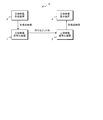
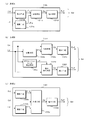
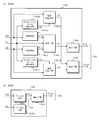
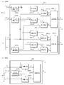
- FIG. 1 is a block diagram illustrating a configuration of a stereoscopic video transmission system including a stereoscopic video encoding device and a stereoscopic video decoding device according to a first embodiment of the present invention. It is a block diagram which shows the structure of the stereo image coding apparatus which concerns on 1st Embodiment of this invention. It is a block diagram which shows the structure of the depth map synthetic
- FIG. 1 It is a block diagram which shows the structure of the depth map synthetic
- 4A and 4B are explanatory diagrams for explaining a state in which a combined depth map is subjected to reduction processing in the stereoscopic video encoding device according to the first embodiment of the present invention, where (a) is an overall depth map, and (b) is a residual depth. Map (c) shows the warp data.
- the stereoscopic video encoding device In the stereoscopic video encoding device according to the first embodiment of the present invention, it is an explanatory diagram for explaining how to reduce the synthesized multi-view video, (a) when reducing one residual video, (B) shows a case where two residual images are reduced. It is explanatory drawing for demonstrating a mode that the residual image
- FIG. 4 is a diagram illustrating a data structure of an encoded multi-view video and depth map in the stereoscopic video encoding device according to the first embodiment of the present invention, where (a) is an encoding reference viewpoint video, and (b) is a code.
- (C) is an encoded overall depth map
- (d) is an encoded residual depth map
- (e) is an encoded overall depth map
- (f) is an encoded residual depth map.
- the stereoscopic video encoding device In the stereoscopic video encoding device according to the first embodiment and the second embodiment, it is a diagram showing a data structure of the encoded parameters, (a) is the encoding management information for the reference viewpoint video or the central viewpoint video, (B) is the encoding management information for the non-reference viewpoint video, (c) is the camera parameter, (d) is the depth type in the first embodiment, and (e) is the depth type in the second embodiment. It is a figure which shows the correspondence of a depth type value and a synthetic
- FIG. 1 It is explanatory drawing for demonstrating a mode that a designated viewpoint image
- the stereoscopic video transmission system S encodes and transmits a multi-view video shot with a camera or the like together with a depth map, and generates a multi-view video at the transmission destination.
- the stereoscopic video transmission system S includes a stereoscopic video encoding device 1, a stereoscopic video decoding device 2, a stereoscopic video creation device 3, and a stereoscopic video display device 4.
- the stereoscopic video encoding device 1 encodes the multi-view video created by the stereoscopic video creation device 3, outputs it as a coded bit string (bit stream) to a transmission path, and transmits it to the stereoscopic video decoding device 2. .
- the stereoscopic video decoding device 2 decodes the encoded bit string transmitted from the stereoscopic video encoding device 1, generates a multi-view video, and outputs it to the stereoscopic video display device 4.
- the stereoscopic video creation device 3 is a camera that can capture a stereoscopic video, a CG (computer graphics) creation device, or the like.
- the stereoscopic video creation device 3 generates a stereoscopic video (multi-view video) and an associated depth map, and generates a stereoscopic video code. Is output to the converter 1.
- the stereoscopic video display device 4 receives the multi-view video generated by the stereoscopic video decoding device 2 and displays the stereoscopic video.
- the encoded bit string is multiplexed, and the encoded video, the encoded depth map, and the encoded information are decoded by the stereoscopic video decoding device 2 or the video is synthesized or displayed. And encoding parameters obtained by encoding parameters necessary for processing. Further, in the present invention, the encoded bit string is multiplexed with identification information for identifying the information type of the predetermined unit for each predetermined unit, and the encoded bit string is serially transmitted from the stereoscopic video encoding device 1 to the stereoscopic video decoding device 2. It is transmitted as a coded bit string.
- the predetermined unit corresponds to a NALU (Network Abstraction Layer Unit) in the MPEG-4 AVC coding standard, and various information is transmitted in units of NALU.
- the encoding method may be based on the MPEG-4 MVC + Depth encoding standard or the 3D-AVC encoding standard.
- the stereoscopic video encoding device 1 (hereinafter referred to as “encoding device 1” as appropriate) according to the first embodiment includes a video synthesis unit 11, a video encoding unit 12, and a depth map synthesis. Means 13, depth map encoding means 14, parameter encoding means 15, and multiplexing means 16 are provided.
- the encoding device 1 viewed as a stereoscopic viewpoint from a reference viewpoint video C that is an image viewed from a reference viewpoint (reference viewpoint), and a left viewpoint (non-reference viewpoint) that is a viewpoint horizontally separated from the reference viewpoint in the left direction.
- a left-view video L that is a video
- a right-view video R that is a video viewed from the right viewpoint (non-reference viewpoint) that is horizontally distant from the reference viewpoint
- a reference viewpoint corresponding to each of these videos The depth map Cd, the left viewpoint depth map Ld, the right viewpoint depth map Rd, and parameters including the encoding management information Hk, the camera parameter Hc, and the depth type Hd are input from the outside.
- the term “external” refers to, for example, the stereoscopic video creation device 3, and is a depth type Hd that specifies a synthesis method of a multi-view video and a depth map, and a part of encoding management information Hk that specifies an encoding method.
- the above may be input via a user interface (input means) (not shown).
- the encoding device 1 generates an encoded bit string BS using these input information and transmits it to the stereoscopic video decoding device 2 (hereinafter referred to as “decoding device 2” as appropriate).
- the encoding management information Hk is information relating to encoding, and includes, for example, sequence management information such as a frame rate and the number of frames, and a profile ID (Identification) indicating a set of tools used for encoding.
- the camera parameter Hc is a parameter for the camera that has captured the input video of each viewpoint, and is the closest distance of the subject, the farthest distance of the subject, the focal length, the coordinate value of the left viewpoint, the coordinate value of the reference viewpoint, the right The coordinate value of the viewpoint is included.
- the camera parameter Hc is, for example, coefficient information for converting a depth value given as a pixel value of the depth map into a pixel shift amount when projecting the depth map or video to another viewpoint using the depth map. Used.
- the depth type Hd is a parameter indicating a method for synthesizing the images C, L, R and the depth maps Cd, Ld, Rd input by the encoding device 1.
- the central viewpoint is the reference viewpoint
- the left viewpoint toward the subject is the left viewpoint (non-reference viewpoint)
- the right viewpoint is the right viewpoint (non-reference viewpoint).
- the left viewpoint may be a reference viewpoint
- the central viewpoint and the right viewpoint may be non-reference viewpoints.
- the reference viewpoint and the non-reference viewpoint are not limited to being separated in the horizontal direction, and may be separated in any direction such as a vertical direction or an oblique direction in which the angle at which the subject is observed from the viewpoint changes.
- the number of non-reference viewpoint videos is not limited to two, and there may be at least one non-reference viewpoint video in addition to the reference viewpoint video C, and may be three or more.
- the number of viewpoints of the multi-view video and the number of viewpoints of the depth map may not be the same.
- a multi-view video a three-view video composed of a reference viewpoint (center viewpoint) video C, a left viewpoint video L, and a right viewpoint video R is input together with depth maps Cd, Ld, and Rd associated therewith. It is explained as a thing.
- the encoding device 1 combines the input video and depth map by a combining method specified by the depth type Hd, and further combines the combined video and depth map, the encoding management information Hk, the camera parameter Hc, and the depth type.
- the parameters including Hd are encoded, multiplexed on the encoded bit string BS, and transmitted to the stereoscopic video decoding device 2.
- the video synthesizing unit 11 inputs the reference viewpoint video C, the left viewpoint video L, the right viewpoint video R, the camera parameter Hc, and the depth type Hd from the outside, and decodes them from the depth map encoding unit 14.
- the composite depth map G′d is input, a composite video G is generated, and is output to the video encoding means 12.
- the depth map encoding means 14 will be described later, it also has a function of decoding the encoded depth map.
- the signal input to the video synthesis unit 11 and the signal output from the video synthesis unit 11 differ depending on the depth type Hd indicating the video and depth map synthesis method, but in FIG. A signal represented by codes C, L, and R is input as video, a signal represented by code G′d is input as a decoding synthesis depth map, and a signal represented by code G is output as a synthesized video. And
- the video encoding means 12 inputs the encoding management information Hk from the outside and the composite video G from the video synthesis means 11 and encodes the composite video G by the encoding method specified by the encoding management information Hk. Thus, the encoded synthesized video g is generated.
- the video encoding unit 12 outputs the generated encoded composite video g to the multiplexing unit 16. Note that the video encoding unit 12 in the present embodiment encodes the video information about the reference viewpoint and the video information about the non-reference viewpoint separately when encoding the synthesized video G, and is different from each other.
- the data is output to the multiplexing means 16 as encoded data in units (NALU). Further, the reference viewpoint video C is encoded without being processed as it is so as to maintain forward compatibility. The structure of encoded video data will be described later.
- the video encoding unit 12 can encode the composite video G using the encoding method specified by the encoding management information Hk from among a plurality of predetermined encoding methods. It is configured as follows.
- the multi-view video is encoded as the composite video G without processing the multi-view video
- the correlation between the reference viewpoint video C and the non-reference viewpoint videos L and R is high.
- the information Hk it is preferable to set so as to permit the inter-viewpoint prediction between the reference viewpoint image C and the non-reference viewpoint images L and R.
- the encoding efficiency of the synthesized video G is improved.
- the residual video is encoded as the composite video G for the non-reference viewpoint, there is no correlation between the reference viewpoint video and the residual video, so inter-view video prediction is prohibited in the encoding management information Hk. It is preferable to set so as to. Thereby, the encoding efficiency of the synthesized video G is improved.
- the residual video will be described later.
- the depth map synthesizing unit 13 inputs depth maps Cd, Ld, Rd, camera parameters Hc, and depth type Hd from the outside, and uses the depth maps Cd, Ld, Rd by the synthesis method specified by the depth type Hd.
- a map Gd is generated, and the generated combined depth map Gd is output to the depth map encoding means 14.
- the composition method of the depth map will be described later.
- the depth maps Cd, Ld, and Rd at each viewpoint are created in advance by, for example, the stereoscopic video creation device 3 (see FIG. 1) and input along with the videos C, L, and R at each viewpoint.
- the depth maps Cd, Ld, and Rd may be generated and used using the images C, L, and R.
- the depth map encoding means 14 inputs the encoding management information Hk from the outside, and the combined depth map Gd from the depth map combining means 13, respectively, and the combined depth map Gd is specified by the encoding management information Hk. To generate a coding synthesis depth map gd and output it to the multiplexing means 16. In addition, the depth map encoding unit 14 generates a decoded combined depth map G′d by decoding the generated encoded combined depth map gd based on the encoding method, and outputs the decoded combined depth map G′d to the video combining unit 11. To do.
- the depth map encoding means 14 in the present embodiment encodes each frame when the composite depth map Gd is composed of a plurality of frames, and multiplexes the encoded data in different units (NALU). Output to means 16.
- NALU units
- the depth map encoding unit 14 like the video encoding unit 12, uses the encoding method specified by the encoding management information Hk from among a plurality of predetermined encoding methods to generate the composite depth map Gd. It is configured to encode. Further, the depth map encoding means 14 also has a decoding function for decoding the encoded combined depth map gd. As the encoding method, the same method as the video encoding means 12 can be used. In the series of stereoscopic video encoding processing, the video encoding unit 12 and the depth map encoding unit 14 may select the same encoding method, or different encoding methods may be selected. It may be.
- the parameter encoding unit 15 receives the encoding management information Hk, the camera parameter Hc, and the depth type Hd from the outside, encodes these parameters by a predetermined encoding method, generates an encoding parameter h, and performs multiplexing. Output to the conversion means 16.
- the parameter encoding unit 15 encodes each parameter as a separate unit (NALU) according to the type of parameter to be encoded. The structure of the parameter encoded data will be described later.
- the multiplexing unit 16 receives the encoding parameter h from the parameter encoding unit 15, the encoded combined video g from the video encoding unit 12, and the encoded combined depth map gd from the depth map encoding unit 14. These encoded information is multiplexed and transmitted to the stereoscopic video decoding apparatus 2 as a series of encoded bit strings BS.
- the depth maps Cd, Ld, and Rd are composed of a depth f corresponding to the foreground subject image F and a depth b corresponding to the background subject image B.
- the brighter the region the greater the depth value, and therefore, it indicates that it is located in front (close to the viewpoint).
- any depth map used in the present embodiment is handled as image data in the same format as a video such as the reference viewpoint video C.
- a depth value is set as the luminance component (Y)
- a predetermined value for example, “128” in the case of an 8-bit signal per component
- the color difference components (Pb, Pr) are set.
- the synthesis method for the depth map is selected from a total of six methods including the five methods from method A to method E and the method of encoding a plurality of depth maps as they are without being processed. It is configured to be selectable.
- 3A (a) to FIG. 3A (c), FIG. 3B (a), and FIG. 3B (b) show configuration examples of the depth map synthesis means 13 corresponding to the methods A to E, respectively. Hereinafter, each method will be described sequentially.
- the method A includes a reference viewpoint depth map Cd and a left viewpoint depth map Ld, which are depth maps in two viewpoints in which the central viewpoint is a reference viewpoint and the left viewpoint is a non-reference viewpoint.
- This is a method of projecting to a predetermined common viewpoint and combining two depth maps projected to the common viewpoint into one.
- the left intermediate viewpoint which is an intermediate viewpoint between the central viewpoint and the left viewpoint, is used as the common viewpoint.
- a common viewpoint may be set anywhere within the range having the central viewpoint and the left viewpoint as both ends.
- the depth map synthesized by the method A is an “entire depth map” having depth values corresponding to all pixels of the video at the common viewpoint.
- the depth map combining unit 13A that combines the depth map by the method A includes a projecting unit 131a, a projecting unit 131b, a combining unit 131c, and a reducing unit 131d. ing.
- the projecting means 131a projects the reference viewpoint depth map Cd, which is the depth map at the central viewpoint input from the outside, to the left intermediate viewpoint, which is the common viewpoint, and generates the depth map Z C d at the left intermediate viewpoint.
- the projecting unit 131a outputs the generated left intermediate viewpoint depth map Z C d to the synthesizing unit 131c.
- the projection of the depth map will be described with reference to FIG.
- the distance from the reference viewpoint to the left viewpoint is b
- the distance from the reference viewpoint to the left designated viewpoint as an arbitrary viewpoint is c
- the distance from the left intermediate viewpoint to the left designated viewpoint is a
- the left designation Let d be the distance from the viewpoint to the left viewpoint.
- the distance from the reference viewpoint to the left intermediate viewpoint and the distance from the left intermediate viewpoint to the left viewpoint are both b / 2.
- the depth value means that when a depth map or video is projected to a viewpoint separated by a distance b which is a distance between the reference viewpoint and the left viewpoint, the pixel is shifted in the right direction opposite to the viewpoint shift direction.
- the shift amount of the number of pixels is proportional to the shift amount of the viewpoint. Accordingly, when the depth map at the reference viewpoint is projected to the left designated viewpoint that is c away from the reference viewpoint, each pixel is shifted to the right by the number of pixels corresponding to (c / b) times the depth value. It will be. Note that when the viewpoint shift direction is the right direction, the pixel is shifted to the opposite left side.
- the depth value ((b / 2) / b) 1 / Shifting to the right by the number of pixels corresponding to twice.
- the projecting unit 131a calculates the depth after projection of the largest pixel value among them.
- the pixel value of the left intermediate viewpoint depth map Z C d which is a map, is used.
- the smaller pixel value among the pixel values located on the left and right of the pixel is set as the pixel value of the left intermediate viewpoint depth map Z C d.
- the projecting means 131b projects the left viewpoint depth map Ld, which is the depth map at the left viewpoint input from the outside, to the left intermediate viewpoint, which is the common viewpoint, and generates the depth map Z L d at the left intermediate viewpoint. .
- the projecting unit 131b can perform projective transformation in the same procedure except that the projecting unit 131a is shifted in a different direction.
- the projecting unit 131b outputs the generated left intermediate viewpoint depth map Z L d to the synthesizing unit 131c.
- the synthesizing unit 131c receives the left intermediate viewpoint depth map Z C d from the projecting unit 131a and the left intermediate viewpoint depth map Z L d from the projecting unit 131b, and synthesizes the two depth maps, thereby combining the two depth maps. Zd is generated.
- the synthesizing unit 131c calculates an average value of pixel values that are depth values for each pixel for the two depth maps, and uses the calculated average value as a pixel value of the combined depth map Zd to thereby calculate the two depths. Synthesize the map.
- the combining unit 131c outputs the generated combined depth map Zd to the reducing unit 131d.
- the reduction unit 131d receives the combined depth map Zd from the combining unit 131c, and the input combined depth map Zd is 1/2 in the vertical direction (vertical) and the horizontal direction (horizontal) as shown in FIG.
- the image is reduced by thinning out to 2, and a reduced composite depth map Z 2 d is generated.
- the depth map combining unit 13A outputs the generated reduced combined depth map Z 2 d as the combined depth map Gd to the depth map encoding unit 14 (see FIG. 2).
- the depth map reduction processing is not limited to 1/2 reduction in length and breadth, but may be other reduction ratios such as 1/3 and 1/4. Also, the vertical and horizontal reduction ratios may be different. Furthermore, the reduction process may not be performed. In this case, the reduction means 131d can be omitted. In other composition methods described later, the depth map is reduced, but it may not be reduced. In this case, the reduction means can be omitted in each synthesis method.
- Method B 2-view 2-type
- the method B is a reference viewpoint depth map Cd and a left viewpoint depth map which are depth maps in two viewpoints in which the central viewpoint is a reference viewpoint and the left viewpoint is a non-reference viewpoint.
- Ld is used to synthesize an overall depth map Zd at the reference viewpoint and a left residual depth map Xd at the left viewpoint.
- the “residual depth map” is an occlusion hole when the depth map Cd at the reference viewpoint is projected onto the left viewpoint, and is generated by cutting out the depth values for pixels that are not projected from the left viewpoint depth map Ld. It is a depth map.
- the occlusion hole is hidden behind the foreground subject in the depth map Cd at the reference viewpoint or protrudes outside the depth map Cd at the reference viewpoint, and exists in the depth map Cd at the reference viewpoint. It refers to a pixel that does not. That is, in the method B, only the depth information that does not overlap with the reference viewpoint depth map Cd is extracted from the left viewpoint depth map Ld that is the entire depth map, and the left residual depth map Xd is generated to reduce the amount of data. To do.
- the depth map combining unit 13B that combines the depth map by the method B includes a projection unit 132a, an occlusion hole detecting unit 132b, a combining unit 132c, and a residual cutting unit 132d.
- a reduction unit 132e and a reduction unit 132f are provided.
- the projection means 132a projects the left viewpoint depth map Ld input from the outside onto the reference viewpoint, and generates a depth map C L d at the reference viewpoint.
- the projecting unit 132a outputs the generated reference viewpoint depth map C L d to the synthesizing unit 132c.
- the occlusion hole detection means 132b receives the reference viewpoint depth map Cd from the outside, and detects an occlusion hole which is an area where pixel values are not projected when the reference viewpoint depth map Cd is projected to the left viewpoint.
- the occlusion hole detection unit 132b generates a hole mask Lh indicating an area to be an occlusion hole, and outputs the hole mask Lh to the residual cutout unit 132d.
- region used as an occlusion hole is mentioned later.
- the synthesizing unit 132c receives the reference viewpoint depth map Cd from the outside and the reference viewpoint depth map C L d from the projection unit 132a, respectively, and synthesizes the two depth maps at the reference viewpoint into one overall depth map Zd.
- the entire depth map Zd is output to the reduction means 132e.
- the synthesizing unit 132c calculates an average value of pixel values that are depth values for each pixel for the two input depth maps, and sets the calculated average value as the pixel value of the entire depth map Zd. Combining two depth maps.
- the reference viewpoint depth map Cd may be used as it is as the entire depth map Zd at the reference viewpoint. In this case, the projection unit 132a and the synthesis unit 132c can be omitted.
- the residual cutting means 132d inputs the left viewpoint depth map Ld from the outside, and the hole mask Lh from the occlusion hole detection means 132b, respectively, and becomes an occlusion hole indicated by the hole mask Lh from the left viewpoint depth map Ld.
- the left residual depth map Xd which is a depth map having only the pixel values of the region that becomes the occlusion hole, is generated.
- the residual cutout unit 132d outputs the generated left residual depth map Xd to the reduction unit 132f.
- the residual cutting means 132d sets a fixed value as the pixel value of the region that does not become an occlusion hole. Thereby, the encoding efficiency of the left residual depth map Xd can be improved.
- the constant value may be 128 as the median value.
- the reducing unit 132e receives the entire depth map Zd from the synthesizing unit 132c and thins out pixels in the same manner as the reducing unit 131d of the above-described method A, thereby reducing the reduced entire depth map Z 2 d at a predetermined reduction rate.
- the generated entire reduced depth map Z 2 d is output to the depth map encoding means 14 (see FIG. 2) as a part of the combined depth map Gd.
- the reduction unit 132f receives the left residual depth map Xd from the residual cutout unit 132d, and thins out the pixels in the same manner as the reduction unit 131d of the method A described above, thereby reducing the image at a predetermined reduction rate.
- a residual depth map X 2 d is generated, and the generated reduced residual depth map X 2 d is output to the depth map encoding means 14 (see FIG. 2) as a part of the combined depth map Gd. That is, the combined depth map Gd in the method B is a combination of the reduced overall depth map Z 2 d and the reduced residual depth map X 2 d.
- the method C is a reference viewpoint depth map Cd that is a depth map in three viewpoints with the central viewpoint as the reference viewpoint and the left viewpoint and the right viewpoint as the non-reference viewpoint.
- the viewpoint depth map Ld and the right viewpoint depth map Rd are respectively projected onto a predetermined common viewpoint, and the three depth maps projected onto the common viewpoint are combined into one.
- the central viewpoint is the common viewpoint. It should be noted that the common viewpoint may be used anywhere as long as the left viewpoint and the right viewpoint are within the range.
- the depth map synthesized by the method C is the entire depth map Zd at the common viewpoint.
- the depth map combining unit 13C that combines the depth map by the method C includes a projecting unit 133a, a projecting unit 133b, a combining unit 133c, and a reducing unit 133d. ing.
- the projecting means 133a projects the right viewpoint depth map Rd input from the outside to the central viewpoint, that is, the reference viewpoint, which is a common viewpoint, and generates a reference viewpoint depth map C R d.
- the projecting unit 133a outputs the generated reference viewpoint depth map C R d to the synthesizing unit 133c.
- the projection means 133b projects the left viewpoint depth map Ld input from the outside to the central viewpoint, that is, the reference viewpoint, which is a common viewpoint, and generates a reference viewpoint depth map C L d.
- the projecting means 133b outputs the generated reference viewpoint depth map C L d to the synthesizing means 133c.
- the synthesizing unit 133c inputs the reference viewpoint depth map Cd from the outside, the reference viewpoint depth map C R d from the projection unit 133a, and the reference viewpoint depth map C L d from the projection unit 133b. Is combined to generate the entire depth map Zd.
- the synthesizing unit 133c calculates the average value of the pixel values that are the depth values for each pixel for the three depth maps, and sets the calculated average value as the pixel value of the entire depth map Zd. Synthesize. Instead of the average value, the median value of the three pixel values may be used.
- the synthesizing unit 133c outputs the generated entire depth map Zd to the reducing unit 133d.
- the common viewpoint is other than the reference viewpoint
- the reference viewpoint depth map Cd is projected onto the common viewpoint, and the left viewpoint depth map Ld and the right viewpoint depth map Rd are respectively projected onto the common viewpoint.
- the entire depth map Zd can be generated by combining them.
- the reduction unit 133d reduces the overall depth map Zd at a predetermined reduction rate by thinning out pixels in the same manner as the reduction unit 131d of the method A, and generates a reduced overall depth map Z 2 d.
- the depth map combining unit 13C outputs the generated reduced overall depth map Z 2 d as the combined depth map Gd to the depth map encoding unit 14 (see FIG. 2).
- the method D is a reference viewpoint depth map Cd, which is a depth map in three viewpoints with the central viewpoint as the reference viewpoint and the left viewpoint and the right viewpoint as the non-reference viewpoint.
- the viewpoint depth map Ld and the right viewpoint depth map Rd the overall depth map Zd at the reference viewpoint, which is the central viewpoint, the residual depth map Xd at the left viewpoint, and the residual depth map Yd at the right viewpoint are synthesized. It is.
- the residual depth map at the right viewpoint is an occlusion hole when the depth map Cd at the reference viewpoint is projected onto the right viewpoint, and is generated by cutting out the depth values for pixels that are not projected from the right viewpoint depth map Rd. It is a depth map. That is, in method D, only depth information that does not overlap with the reference viewpoint depth map Cd is extracted from the depth maps at the two non-reference viewpoints, and the left residual depth map Xd and the right residual depth map Yd are generated. The amount of data is reduced.
- the projecting means 134 L a projects the left viewpoint depth map Ld input from the outside onto the reference viewpoint, and generates a depth map C L d at the reference viewpoint.
- the projecting unit 134 L a outputs the generated reference viewpoint depth map C L d to the synthesizing unit 134 c.
- the projection unit 134 Ra projects the right viewpoint depth map Rd input from the outside onto the reference viewpoint, and generates the depth map C R d at the reference viewpoint.
- the projecting unit 134 R a outputs the generated reference viewpoint depth map C R d to the synthesizing unit 134 c.
- the occlusion hole detection means 134 L b detects the occlusion hole that is an area where pixel values are not projected when the reference viewpoint depth map Cd is input from the outside and the reference viewpoint depth map Cd is projected to the left viewpoint. .
- the occlusion hole detection unit 134 L b generates a hole mask Lh indicating an area to be an occlusion hole, and outputs the hole mask Lh to the residual extraction unit 134 L d.
- the occlusion hole detection means 134 R b detects the occlusion hole that is an area in which pixel values are not projected when the reference viewpoint depth map Cd is input from the outside and the reference viewpoint depth map Cd is projected to the right viewpoint. .
- the occlusion hole detection unit 134 R b generates a hole mask Rh indicating an area to be an occlusion hole, and outputs the hole mask Rh to the residual extraction unit 134 R d.
- Combining means 134c is a reference viewpoint depth map Cd externally, the reference viewpoint depth map C L d from the projection means 134 L a, the reference viewpoint depth map C R d from the projection means 134 R a, type respectively, the reference viewpoint Are combined into one overall depth map Zd, and the combined overall depth map Zd is output to the reduction means 134e.
- the synthesizing unit 134c synthesizes the three depth maps in the same manner as the synthesizing unit 133c of the method C described above.
- the reference viewpoint depth map Cd may be used as it is as the entire depth map Zd at the reference viewpoint. In this case, the synthesizing unit 134c can be omitted.
- the residual cutting means 134 L d inputs the left viewpoint depth map Ld from the outside and the hole mask Lh from the occlusion hole detection means 134 L b, respectively, and the occlusion indicated by the hole mask Lh from the left viewpoint depth map Ld. A pixel value of a region to be a hole is cut out, and a left residual depth map Xd that is a depth map having only the pixel value of the region to be an occlusion hole is generated. The residual cutting means 134 L d outputs the generated left residual depth map Xd to the reducing means 134 f.
- the residual cutting means 134 R d inputs the right viewpoint depth map Rd from the outside, the hole mask Rh from the occlusion hole detection means 134 R b, and the occlusion indicated by the hole mask Rh from the right viewpoint depth map Rd. A pixel value of a region that becomes a hole is cut out, and a right residual depth map Yd that is a depth map having only pixel values of a region that becomes an occlusion hole is generated.
- the residual cutting unit 134 R d outputs the generated right residual depth map Yd to the reducing unit 134 f.
- the residual cutting means 134 L d and 134 R d preferably set a constant value as the pixel value of the region that does not become an occlusion hole, similarly to the residual cutting means 132 d of the method B described above.
- the reducing unit 134e receives the entire depth map Zd from the synthesizing unit 134c, and generates the reduced entire depth map Z 2 d reduced at a predetermined reduction rate in the same manner as the reducing unit 131d of the method A described above.
- the reduced overall depth map Z 2 d is output to the depth map encoding means 14 (see FIG. 2) as a part of the combined depth map Gd.
- the reduction means 134f is left residual depth map Xd from the residual cutting means 134 L d, respectively input the right residual depth map Yd from the residual cutting means 134 R d, respectively, a predetermined reduction ratio
- the left reduced residual depth map X 2 d and the right reduced residual depth map Y 2 d that have been reduced by (for example, 1/2 both vertically and horizontally) and further reduced to 1/2 in the vertical or horizontal direction are As shown in FIG. 5B, a reduced residual depth map XY 2 d synthesized into one frame is generated.
- Reduction means 134f outputs as part of the generated reduced residual depth map XY 2 d synthesis depth map Gd, the depth map encoding means 14 (see FIG. 2). That is, the combined depth map Gd in the method D is a combination of the reduced overall depth map Z 2 d and the reduced residual depth map XY 2 d.
- FIG. 5B is an example in which the frame is formed by reducing the length in the vertical direction to 1 ⁇ 2 and connecting two residual depth maps in the vertical direction.
- the left and right residual depth maps Xd, Yd may be reduced or output to the depth map encoding means 14 (see FIG. 2) without changing the frame, or with the same magnification.
- the standard E is a reference viewpoint depth map Cd and a left viewpoint depth map that are depth maps in two viewpoints with the central viewpoint as the reference viewpoint and the left viewpoint as the non-reference viewpoint.
- a depth map (hereinafter referred to as warp data) is generated by smoothly changing the depth value on the background side where the depth value is small in the portion where the depth value changes abruptly (edge portion). To do.
- ⁇ Occlusion does not occur in the projected image using warp data in which the part where the depth value changes abruptly is changed smoothly. For this reason, even if the stereoscopic video decoding device 2 (see FIG. 1) synthesizes video using either the center warp data Cw or the left warp data Lw as the depth map, a smooth video can be synthesized.
- the depth map combining unit 13E that combines the depth map by the method E includes a warping unit 135a, a warping unit 135b, and a reduction unit 135c.
- the warping unit 135a inputs the reference viewpoint depth map Cd from the outside, and “warps” to smoothly change the depth value on the background side where the depth value is small in the portion where the depth value changes abruptly (edge portion).
- the central warp data Cw is generated.
- the warping unit 135a outputs the generated central warp data Cw to the reduction unit 135c.
- the range in which the depth value is smoothly changed is an area where pixels overlap when the reference viewpoint depth map Cd, which is the depth map at the central viewpoint, is projected to the left viewpoint, that is, the foreground subject.
- This corresponds to a region on the right side of the right edge of the depth f of the image F and a region having a predetermined width on the left side of the left edge of the depth f of the foreground subject image F.
- the predetermined width can be determined as appropriate.
- the predetermined width can be set to be approximately the same as the region width for smoothly changing the depth value on the right side of the right edge.
- linear interpolation may be performed using the depth values at the left and right ends of the range, or curve interpolation using a spline function or the like may be performed. Also good.
- the edge of the texture in the video is detected from the reference viewpoint video C which is the video corresponding to the reference viewpoint depth map Cd, and the center warp data Cw is generated by weighting the depth value of the detected portion of the edge. It may be. Thereby, it is possible to reduce the positional deviation between the edge in the video and the depth value of the central warp data Cw.
- the warping unit 135b inputs the left viewpoint depth map Ld from the outside, warps the input left viewpoint depth map Ld, and generates the left warp data Lw.
- the warping unit 135b outputs the generated left warp data Lw to the reduction unit 135c.
- the range in which the depth value is smoothly changed is a range having an effective pixel value in the left residual depth map Xd of the above-described method B (the left side of the depth f corresponding to the foreground subject image F).
- the left warp data Lw is generated by this procedure.
- the predetermined width can be determined as appropriate.
- the predetermined width can be approximately the same as the region width in which the depth value is smoothly changed on the left side of the left edge. Note that the method of smoothly changing the depth value is the same as that in the case of the above-described central warp data Cw, and the description thereof will be omitted.
- the reducing unit 135c receives the central warp data Cw from the warping unit 135a and the left warp data Lw from the warping unit 135b, respectively, and reduces the image vertically and horizontally at a predetermined reduction rate (for example, 1/4). As shown in FIG. 5C, the reduced warp data CL 2 w synthesized into one frame is generated by reducing the length in the vertical direction or the horizontal direction to 1/2 and connecting in the vertical or horizontal direction. The reducing unit 135c outputs the generated reduced warp data CL 2 w to the depth map encoding unit 14 (see FIG. 2) as a combined depth map Gd.
- a predetermined reduction rate for example, 1/4
- FIG. 5C shows an example of the further reduction as described above, in which the image is reduced to 1/2 in the vertical direction and connected in the vertical direction to form a frame.
- the warped depth map has a smooth change in depth value, so that, for example, 1/4, less information is lost even if it is reduced to a smaller size. For this reason, it is possible to reduce the amount of data by reducing the reduction rate.
- the predetermined reduction ratio for reducing the warp data may be another reduction ratio such as 1/2 or 1/3, or may be equal.
- the central warp data Cw and the left warp data Lw may be reduced or output as they are as individual data to the depth map encoding means 14 (see FIG. 2) without being framed.
- FIGS. 7 to 11 (Video composition method) Next, referring to FIGS. 7 to 11 (refer to FIGS. 1, 2 and 4 as appropriate), the video composition method in the video composition means 11 will be described.
- Depth maps Cd, Ld, and Rd are input.
- the central viewpoint is the reference viewpoint, and the left viewpoint and the right viewpoint are non-reference viewpoints.
- one of the three types of video composition methods is selected in correspondence with the above-described five types of depth map composition methods A to E.
- Method A 2-viewpoint 1 type
- Method B 2-viewpoint 2 type
- the central viewpoint video C and the left viewpoint video L are used as they are, and the central viewpoint video C is used as it is as the reference viewpoint video.
- a left residual video X obtained by cutting out a residual video from the video L is generated. That is, one reference viewpoint video at the central viewpoint and one residual video at the left viewpoint are generated as the synthesized video G.
- the “residual image” is an image generated by cutting out the pixel of the region that becomes an occlusion hole when the reference viewpoint image C is projected to the left viewpoint from the left viewpoint image L. That is, in the method A and the method B, only the pixel information that does not overlap with the reference viewpoint video C is extracted from the left viewpoint video L in the composite video G, and the left residual video X is generated, thereby reducing the data amount. To do.
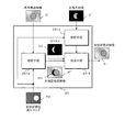
- FIG. 10 is a block diagram excerpting a configuration necessary for explaining the generation of the residual video in the video synthesizing unit 11 of the encoding device 1 shown in FIG. Further, in the example shown in FIG. 10, it is assumed that the reference viewpoint video C and the left viewpoint video L are composed of a subject on a circular foreground and a subject on the other background.
- the occlusion hole OH will be described.
- the case where the reference viewpoint video C is projected to the left viewpoint using the left viewpoint depth map L C d obtained by projecting the reference viewpoint depth map Cd to the left viewpoint will be described as an example.
- the pixel of the subject that is the foreground close to the viewpoint position is projected to a position greatly shifted by the shift of the viewpoint position.
- a subject pixel that is a background far away from the viewpoint position is projected to a position that hardly shifts due to the shift of the viewpoint position.
- the region shown in black in a crescent shape remains as a region where pixels are not projected.
- An area where this pixel is not projected is an occlusion hole OH.
- an occlusion hole is generally generated when an image is projected to an arbitrary viewpoint using a depth map related to the image (the viewpoint does not have to be the same as the image).
- the residual cutting unit 111d extracts the pixels in the pixel area in the occlusion hole OH from the left viewpoint video L to generate the left residual video X.
- the residual video excluding the pixel area that can be projected from the reference viewpoint video C, not the entire left viewpoint video L, is encoded, so that the encoding efficiency is good and the amount of data to be transmitted can be reduced. it can.
- the depth value of the background is “0”, that is, at infinity.
- the depth value of the background is not “0” and there are pixels that protrude outside the reference viewpoint video C, such pixels are also included in the residual video.
- the video composition unit 11 uses the left viewpoint depth map L C d to detect the region that becomes the occlusion hole OH by the occlusion hole detection unit 111c, and shows the region that becomes the occlusion hole OH.
- a hole mask Lh is generated.
- a white area indicates an area that becomes an occlusion hole OH.
- the video synthesizing unit 11 extracts the pixels in the region that becomes the occlusion hole OH indicated by the hole mask Lh from the left viewpoint video L by the residual cutout unit 111d to generate the left residual video X.
- a method for detecting (predicting) a pixel region that becomes an occlusion hole using the left viewpoint depth map L C d will be described with reference to FIG.
- a right neighboring pixel (a pixel in the figure) of a pixel of interest (a pixel indicated by a cross in the figure) that is a determination target of whether or not the pixel is an occlusion hole.
- the pixel of interest has a depth value larger than the depth value of the pixel of interest, it is determined that the pixel of interest is a pixel that becomes an occlusion hole and indicates that it is a pixel that becomes an occlusion hole.
- a hole mask Lh is generated. In the hole mask Lh shown in FIG. 11, pixels that become occlusion holes are shown in white, and other pixels are shown in black.
- a method for detecting a pixel serving as an occlusion hole will be described in more detail.
- the depth value at the pixel of interest is x
- the depth value at a pixel away from the pixel of interest by a predetermined number of pixels Pmax in the right direction is y.
- the predetermined number of pixels Pmax separated in the right direction is, for example, the number of pixels corresponding to the maximum amount of parallax in the corresponding video, that is, the amount of parallax corresponding to the maximum depth value.
- the depth value in the right neighboring pixel is z.
- it is determined that the pixel of interest is a pixel that becomes an occlusion hole.
- Equation (1) k is a predetermined coefficient, and can be a value of about “0.8” to “0.6”, for example.
- the “predetermined value” can be set to “4”, for example.
- a discontinuous portion with a small depth value that hardly causes occlusion is not detected, and the left residual
- the number of pixels extracted as the difference video can be suppressed, and the data amount of the encoded residual video described later can be suppressed.
- the entire depth map is at the reference viewpoint as in the scheme B, the scheme C, and the scheme D illustrated in FIG. 4, pixels are not projected when the entire depth map is projected to the left viewpoint or the right viewpoint.
- the area may be an occlusion hole.
- the video compositing means 11A for composing the video corresponding to the system A and the system B includes a size restoring means 111a, a projecting means 111b, an occlusion hole detecting means 111c, and a residual cutting unit.
- An output unit 111d and a reduction unit 111e are provided.
- the size restoration unit 111a receives the decoding combined depth map G′d from the depth map encoding unit 14 (see FIG. 2), and the reduction unit 131d (see FIG. 3A (a)) of the depth map combining unit 13A according to the method A. ) Or the reduced overall depth map Z ′ 2 d in the decoded combined depth map G′d reduced by the reducing means 132e (see FIG. 3A (b)) of the depth map combining means 13B by the method B is used for each method. By enlarging at a corresponding enlargement ratio, the entire depth map Z′d restored to the original size is generated. The size restoration unit 111a outputs the generated entire depth map Z′d to the projection unit 111b.
- the projection unit 111b receives the entire depth map Z′d from the size restoration unit 111a, and projects the input entire depth map Z′d on the left viewpoint to generate a left viewpoint depth map L′ d.
- the projecting unit 111b outputs the generated left viewpoint depth map L′ d to the occlusion hole detecting unit 111c.
- the projecting unit 111b performs projective conversion from the left intermediate viewpoint to the left viewpoint.
- the projecting unit 111b performs projective conversion from the reference viewpoint to the left viewpoint.
- the decoding synthesized depth map G′d is used with its size restored, but this allows the stereoscopic video decoding device 2 (see FIG. 1) side to identify the occlusion hole. This is preferable because the region can be predicted more appropriately.
- the synthesized depth map Gd generated by the depth map synthesizing unit 13 may be used by restoring the size instead of the decoded synthesized depth map G′d. The same applies to the occlusion hole detection of the image synthesizing means 11B by the method C and the method D described later.
- the occlusion hole detection unit 111c receives the left viewpoint depth map L′ d from the projection unit 111b, and projects the reference viewpoint video C to the left viewpoint using the input left viewpoint depth map L′ d. A region to be formed is detected (predicted) by the above-described method, and a hole mask Lh indicating the region is generated. The occlusion hole detection unit 111c outputs the generated hole mask Lh to the residual cutout unit 111d.
- the residual cut-out means 111d inputs the left viewpoint video L from the outside and the hole mask Lh from the occlusion hole detection means 111c, respectively, and the pixels shown as the regions to be occlusion holes by the hole mask Lh are the left viewpoint video L To generate a left residual video X. Note that, as shown in the uppermost row in FIG. 8, the pixel in the vicinity of the left end portion of the left viewpoint video L is also pixel information that does not include the range corresponding to the depth value in the reference viewpoint video C. Add to video X. In addition, the residual cutout unit 111d outputs the generated left residual video X to the reduction unit 111e.
- a pixel value is set as a pixel value for a region where no pixel is extracted, or an average value for all the pixels of the left residual video X is set as the pixel value.
- the encoding efficiency of the left residual video X can be improved.
- the reduction means 111e receives the left residual video X from the residual cutout means 111d, and reduces the left residual video X by reducing the input residual video X at a predetermined reduction ratio as shown in FIG. 9A. generating a residual image X 2.
- Reduction means 111e the generated left reduced residual picture X 2 as part of a composite video G, and outputs the video coding unit 12 (see FIG. 2).
- the video synthesizing unit 11A corresponding to the scheme A or the scheme B outputs the reference viewpoint video C as it is to the video encoding unit 12 (see FIG. 2) as a part of the synthesized video G.
- the vertical and horizontal directions can be 1 ⁇ 2.
- the left residual video X may be reduced and fitted into the original size frame. In this case, for there is no blank area left reduced residual picture X 2, it is sufficient to set the predetermined pixel value set in the pixel extraction area outside the Hidarizansa image X.
- the reduction process of the left residual video X is not limited to reduction to 1/2 in the vertical and horizontal directions, and may be other reduction ratios such as 1/3 and 1/4. Also, the vertical and horizontal reduction ratios may be different. Furthermore, the reduction process may not be performed. In this case, the reduction unit 111e can be omitted.
- the central viewpoint video C is directly used as the reference viewpoint video using the central viewpoint video C, the left viewpoint video L, and the right viewpoint video R. And generating a left residual video X obtained by cutting out a residual video from the left viewpoint video L and a right residual video Y obtained by cutting out a residual video from the right viewpoint video R. That is, one reference viewpoint video at the central viewpoint and two residual videos at the left viewpoint and the right viewpoint are generated as the synthesized video G.
- the left residual video X is the same as the left residual video X of the composite video corresponding to the scheme A and the scheme B.
- the right residual video Y is a video generated by cutting out the pixels of the region that becomes an occlusion hole when the reference viewpoint video C is projected to the right viewpoint from the right viewpoint video R.
- the right residual video Y can be generated in the same manner as the left residual video X, except that the right and left positional relationships differ with respect to the reference viewpoint. That is, in the method C and the method D, only pixel information that does not overlap with the reference viewpoint video C is extracted from the left viewpoint video L and the right viewpoint video R that are non-reference viewpoint videos, and the left residual video X and the right residual video are extracted. The amount of data is reduced by generating the difference video Y.
- the size restoration unit 112a receives the decoding combined depth map G′d from the depth map encoding unit 14 (see FIG. 2), and the reduction unit 133d (see FIG. 3A (c)) of the depth map combining unit 13C according to the method C. ) Or the reduced overall depth map Z ′ 2 d in the decoded combined depth map G′d reduced by the reducing means 134e (see FIG. 3B (a)) of the depth map combining means 13D by the method D is used for each method. By enlarging at a corresponding enlargement ratio, the entire depth map Z′d restored to the original size is generated.
- the size restoration unit 112a outputs the generated entire depth map Z′d to the projection unit 112 L b and the projection unit 112 R b.
- the projection unit 112 L b, the occlusion hole detection unit 112 L c, and the residual cutout unit 112 L d are respectively the projection unit 111 b, the occlusion hole detection unit 111 c, and the residual cutout shown in FIG. Since it is the same as that of the means 111d, a detailed description is omitted.
- projection means 112 R b, occlusion hole detection unit 112 R c and the residual cutting means 112 R d is, projection means 111b shown in FIGS 7 (a), occlusion hole detection unit 111c and the residual cutting means 111d is the same as the reference point 111d except that the positional relationship on the left and right with respect to the reference viewpoint is different.
- projection means 112 R b outputs a right viewpoint depth map R'd to occlusion hole detection unit 112 R c
- occlusion hole detection unit 112 R c outputs a hole mask Rh to residual cutting means 112 R d
- the residual cutting unit 112 L d outputs the generated left residual video X to the reducing unit 112 e
- the residual cutting unit 112 R d outputs the generated right residual video Y to the reducing unit 112 e.
- Reduction means 112e is left residual picture X from the residual cutting means 112 L d, enter the right residual picture Y respectively from the residual cutting means 112 R d, respectively, a predetermined reduction ratio (for example, vertical and horizontal both the left reduced residual picture X 2 and right reduced residual picture Y 2 obtained by reducing by 1/2), 9 (as shown in b), 1 single synthesized framed with a frame reduced residual picture XY 2 Is generated.
- Reduction means 112e the generated framed reduced residual picture XY 2 as part of a composite video G, and outputs the video coding unit 12 (see FIG. 2).
- FIG. 9B is an example in which the frames are connected in the vertical direction.
- the left and right residual videos X and Y may be reduced without being framed, or may be output as they are to the video encoding means 12 (see FIG. 2). Further, the reduction ratios in the vertical direction and the horizontal direction may be different.
- Method E Type 3
- the reference viewpoint video C and the left viewpoint video L are respectively used as they are as shown in the third row of FIG. That is, as shown in FIG. 7C, the video compositing means 11C corresponding to the method E uses the reference viewpoint video and the non-reference viewpoint left viewpoint video as the composite video G. Accordingly, the two videos are output to the video encoding means 12 (see FIG. 2) without being processed.
- composition methods for the depth map and the video have been described.
- the composition method is not limited to these, and instead of or in addition to some or all of these methods, Other schemes can also be configured to be selectable.
- the present invention is not limited to the selection of all five types of synthesis methods, and one or more of them may be used.
- the above-described method A (two-viewpoint type 1) can be extended to a composition method using a three-viewpoint image and a depth map.
- FIG. 12 (refer to FIG. 4 and FIG. 8 as appropriate)
- a case where the method A is extended to three viewpoints will be described.
- the depth map at the intermediate viewpoint between the reference viewpoint and the left viewpoint is used by using the reference viewpoint depth map Cd and the left viewpoint depth map Ld.
- a left composite depth map Md is generated.
- a right composite depth map Nd that is a depth map at an intermediate viewpoint between the reference viewpoint and the right viewpoint is generated using the reference viewpoint depth map Cd and the right viewpoint depth map Rd.
- the left reduced composite depth map M 2 d and the right reduced depth obtained by reducing the left composite depth map Md and the right composite depth map Nd at a predetermined reduction ratio (for example, 1/2 in the horizontal direction and not reduced in the vertical direction), respectively.
- a combined depth map N 2 d is generated, and for example, a framed reduced combined depth map MN 2 d that is joined in the horizontal direction and combined into one frame is generated. Then, the framed reduced composite depth map MN 2 d may be encoded as a composite depth map Gd.
- the left residual video X and the right residual video Y are generated in the same manner as in the method C and the method D. Then, like the depth map method A, respectively generate the left reduced residual picture X 2 and right reduced residual picture Y 2 which is reduced at a predetermined reduction ratio. Then, a framed reduced residual image XY 2 is generated by combining these into one frame. That is, the reference viewpoint image C, it is possible to generate a composite image G comprising a residual image at two viewpoints from framed framed reduced residual picture XY 2 Prefecture.
- FIG. 12B shows a residual image when the depth value of the background is “0”.
- the encoded bit string is transmitted by a method compliant with the MPEG-4 AVC encoding standard. Therefore, the data unit is composed of various information in units of NALU in the MPEG-4 AVC encoding standard.
- the encoded reference viewpoint video data structure D10 which is data obtained by encoding the video for the reference viewpoint or the central viewpoint, has a start code D100 at the head, and then the reference viewpoint.
- a NALU type D101 having a value of “5” or “1”.
- an encoded reference viewpoint video (or encoded central viewpoint video) D102 is included thereafter.
- the value “5” of the NALU type D101 is added to the encoded video that is intra-frame encoded in the reference viewpoint video, and the value “1” is added to the encoded video that is inter-frame encoded.
- the start code D100 is assigned with “001” as a predetermined value of 3 bytes, and all types of NALU have it at the head. All NALUs have a NALU type that is identification information for identifying the type of information after the start code D100, and a unique value is assigned to each type of information.
- the NALU type is 1-byte information.
- the data structure D11 of the encoded residual video which is data obtained by encoding the video for the non-reference viewpoint, has a start code D100 at the head, and then the non-reference viewpoint.
- the NALU type D111 having a value “20” is included.
- a value “0” is assigned as an SVC (Scalable Video Coding) extension flag D112.
- SVC extension flag is 1-bit length information.
- the video is decomposed into a plurality of resolution videos of the reference resolution video and the residual resolution video and encoded. It is a flag which shows.
- encoding a plurality of viewpoint videos as a reference viewpoint video and a residual video thereof it indicates that the video is encoded as a residual video of a multi-view video by setting “0” as the value of the SVC extension flag. Is.
- the view ID (D113) is included as information indicating the viewpoint position of the non-reference viewpoint.
- the value “0” indicates the reference viewpoint
- the value “1” indicates the left viewpoint
- the value “2” indicates the right viewpoint.
- the value “1” is set as the view ID (D113). Then, it has an encoded residual video (or encoded non-reference viewpoint video) D114 after that.
- the depth map encoding means 14 conforming to the MPEG-4 MVC + Depth encoding standard or the 3D-AVC encoding standard is used, as shown in FIG. 13C, the entire depth map is encoded.
- the data structure D12 of a certain coded entire depth map has a start code D100 at the head, and then has a NALU type D121 having a value of “21” as identification information for identifying the entire depth map.
- the value “21” is also set for the central warp data Cw in the method E as the NALU type D121.
- the value “0” is set as the SVC (Scalable Video Coding) extension flag D122.
- it has view ID (D123) as viewpoint information which shows the viewpoint position of this whole depth map.
- the value “0” is set as the view ID (D123).
- the encoding whole depth map (or encoding center warp data) D124 When synthesizing the depth map by the method A, the viewpoint of the entire depth map is at an intermediate viewpoint position between the central viewpoint and the left viewpoint. In this case, the value “0” is set as the view ID.
- the fact that this viewpoint position is the left intermediate viewpoint position can be identified from the fact that the depth type value indicating the composition method is “0”.
- a data structure D13 of an encoded residual depth map which is data obtained by encoding a residual depth map, has a start code D100 at the head, and then is a residual depth map.
- a NALU type D131 having a value of “21” is included. Note that the value “21” is also assigned to the left warp data Lw in method E as the NALU type D131.
- a value “0” is assigned as an SVC (Scalable Video Coding) expansion flag D132.
- it has view ID (D133) as viewpoint information which shows the viewpoint position of this residual depth map.
- the value “1” is set as the view ID (D133) in order to distinguish it from the entire depth map.
- it has an encoding residual depth map (or encoding left warp data) D134.
- a value “0” is set as the view ID and encoded with the data structure D12 shown in FIG.
- This value “0” is an undefined value in the MPEG-4 AVC coding standard and its extended standard such as MVC.
- the separating means 21 (see FIG. 16) of the decoding device 2 to be described later can identify that this data is the combined depth map gd.
- the separation unit 21 (see FIG. 16) of the decryption apparatus 2 converts the data structure D10 shown in FIG. 13A by deleting the inserted NALU type D141 having the value “0”. It outputs to the depth map decoding means 24 (refer FIG. 16). Accordingly, the depth map decoding unit 24 (see FIG. 16) can correctly decode this data as a NALU having a NALU type D101 conforming to the MVC encoding standard.
- the composite depth map is also immediately after the start code D100 at the head.
- a NALU type D151 having a value of “0” is inserted.
- the separating means 21 (see FIG. 16) of the decoding device 2 described later can identify that this data is a composite depth map.
- the separation means 21 (see FIG. 16) of the decryption device 2 converts the data structure D11 shown in FIG. 13B by deleting the inserted NALU type D151 having the value “0”. It outputs to the depth map decoding means 24 (refer FIG. 16). Accordingly, the depth map decoding unit 24 (see FIG. 16) can correctly decode this data as a NALU having the NALU type D111 conforming to the MVC encoding standard.
- the data structure D20 of the encoding parameter h that encodes SPS (Sequence Parameter Set) that is the encoding management information for the reference viewpoint video (or the central viewpoint video) starts at the head. It has a code D100, and then has a NALU type D201 having a value of “7” as identification information for identifying the coding management information (SPS) for the reference viewpoint video. Next, for example, a value “100” is set as the profile ID (D202) which is 1-byte information indicating a set of tools that encode the reference viewpoint video. After that, the encoding management information D203 regarding the reference viewpoint video (or the central viewpoint video) is included.
- SPS Sequence Parameter Set
- S_SPS Subscribeset_Sequence Parameter Set
- a value “118”, “128”, “138”, “139”, or “140” is set as the profile ID (D212) that is information indicating a set of tools that encode the non-reference viewpoint video. Is done.
- it has encoding management information D213 about the non-reference viewpoint video.
- the value “118” of the profile ID indicates a case where the composite video or the composite depth map is encoded by the MVC encoding tool which is an extension of the MPEG-4 AVC encoding standard
- the value “128” is The case of encoding with the stereo encoding tool
- the value “138” indicates the case of encoding with the MVC + Depth encoding tool
- the value “139” indicates the case of encoding with the 3D-AVC encoding tool It is.
- the value “140” can be set.
- the value “140” is an undefined value in the MPEG-4 AVC encoding standard and its extended standard. For this reason, by using the value “140” as the profile ID, when a conventional decoding device based on the MPEG-4 AVC coding standard and its extended standard receives this coded bit string, an unknown coding method is used. Stop decryption. As a result, it is possible to prevent a malfunction that a conventional decoding device synthesizes an erroneous multi-view video.
- camera parameters are encoded as SEI (Supplemental Enhancement Information) messages that are information for decoding and displaying video.
- SEI Supplemental Enhancement Information
- the data structure D22 of the encoding parameter h obtained by encoding the camera parameter has a start code D100 at the head and the value as identification information for identifying the next SEI message.
- As a 1-byte information identifying that it has a camera parameter as an SEI message it has a payload type D222 whose value is “50”. After that, it has a camera parameter D223.
- the SEI message is used to transmit various kinds of information for video decoding and display. However, only one piece of related data for each type of information of one type is stored in one NALU. Is included.
- the depth type indicating the method for combining the depth map and the video is encoded as the SEI message described above.
- the data structure D23 of the encoding parameter h obtained by encoding the depth type has a start code D100 at the head, and is a value as identification information for identifying the next SEI message.
- a payload type D232 having a value of “53” is included.
- it has a depth type value D233.
- the depth type data structure shown in FIG. 14E will be described in the second embodiment.
- the values “0” to “4” indicate the methods A to E, respectively.
- the values “5” and “6” are undefined, and the value “7” is assigned as an extension code for adding a depth type.
- the stereoscopic video decoding device 2 does not process the video and the depth map when the depth type is not transmitted from the encoding device 1, and the original multi-view video.
- the multi-view depth map is encoded and transmitted.
- the stereoscopic video decoding device 2 decodes the encoded bit string BS transmitted from the stereoscopic video encoding device 1 shown in FIG. 2 via a transmission path, and generates a multi-view video. Therefore, the encoded bit sequence BS is multiplexed with the encoded composite video g, the encoded composite depth map gd, and the encoding parameter h necessary for decoding, combining or displaying the multi-view video.
- the stereoscopic video decoding device 2 includes a separation unit 21, a parameter decoding unit 22, and a video decoding unit. Means 23, depth map decoding means 24, and multi-view video composition means 25 are provided.
- the separating means 21 receives the encoded bit sequence BS transmitted from the encoding device 1, and from the encoded bit sequence BS, the encoded encoding parameter h, the encoded combined video g, and the encoded combined depth map. gd are separated from each other.
- the separating unit 21 outputs the separated encoding parameter h to the parameter decoding unit 22, the encoded combined video g to the video decoding unit 23, and the encoded combined depth map gd to the depth map decoding unit 24. .
- the parameter decoding means 22 receives the encoding parameter h from the separating means 21, decodes the input encoding parameter h, and outputs it to other constituent means according to the parameter type.
- the parameter decoding unit 22 outputs the depth type Hd and the camera parameter Hc to the multi-view video synthesis unit 25 and the encoding management information Hk to the video decoding unit 23 and the depth map decoding unit 24, respectively.
- the video decoding unit 23 receives the encoded synthesized video g from the separating unit 21 and the encoding management information Hk from the parameter decoding unit 22, and indicates the encoding method of the video included in the encoding management information Hk. With reference to the profile ID (see data structures D20 and D21 shown in FIGS. 14A and 14B), the encoded synthesized video g is decoded according to the encoding method. The video decoding unit 23 outputs the generated decoded combined video G ′ to the multi-view video combining unit 25.
- the depth map decoding unit 24 inputs the encoding synthesis depth map gd from the separating unit 21 and the encoding management information Hk from the parameter decoding unit 22, and encodes the depth map included in the encoding management information Hk.
- the profile ID (see the data structure D21 shown in FIG. 14B) is referred to, and the coded synthesis depth map gd is decoded according to the coding method.
- the depth map decoding unit 24 outputs the generated decoding combined depth map G′d to the multi-view video combining unit 25.
- the multi-view video synthesizing unit 25 receives the depth type Hd and camera parameter Hc from the parameter decoding unit 22, the decoded synthesized video G ′ from the video decoding unit 23, and the decoded synthesized depth map G from the depth map decoding unit 24. 'd' is input, and using these pieces of information, for example, a video for a designated viewpoint input from the outside via a user interface is synthesized.
- the multi-view video synthesizing unit 25 outputs the synthesized multi-view video P, C ′, Q and the like to the stereoscopic video display device 4 (see FIG. 1), for example.
- FIG. 17 is a block diagram excerpting the configuration necessary for explaining the generation of multi-view video by the method A in the multi-view video synthesis means 25 of the decoding device 2 shown in FIG. is there.
- the reference viewpoint video C ′, the left residual video X ′, and the like are obtained from a subject in a circular foreground and other background subjects as in the example shown in FIG. It shall be configured.
- the left designated viewpoint video P which is the video at the left designated viewpoint designated between the reference viewpoint and the left viewpoint, is decoded with the decoded reference viewpoint video C ′ and the decoded left residual video X ′.
- the overall depth map (not shown) at the left intermediate viewpoint is synthesized using the left designated viewpoint depth map Pd projected onto the left designated viewpoint.
- the multi-view video composition unit 25 projects the reference viewpoint video C ′ to the left designated viewpoint using the left designated viewpoint depth map Pd by the projecting unit 251d, and the left designated viewpoint video P C. Is generated.
- occlusion hole OH (crescent black area in FIG. 17) is generated in the left specified viewpoint video P C.
- the multi-viewpoint image synthesizing unit 25 generates a hole mask Lh indicating a region to be the occlusion hole OH by the projecting unit 251d.
- a crescent-shaped white region is a region that becomes an occlusion hole OH.
- the multi-view video composition unit 25 projects the left residual video X ′ onto the left designated viewpoint using the left designated viewpoint depth map Pd by the projecting unit 251e. Then, the multi-view video synthesis unit 25 extracts pixels corresponding to the position of the occlusion hole OH indicated by the hole mask Lh from the residual video projected to the left designated viewpoint by the synthesis unit 251f. complement to the specified viewpoint video P C. As a result, the left designated viewpoint video P without the occlusion hole OH is synthesized. In this example, the multi-view video is synthesized using the entire depth map at the left intermediate viewpoint as the depth map, but a depth map at another viewpoint can also be used.
- the decoding device 2 in the present embodiment shown in FIG. 16 does not process the five types of synthesis methods (method A to method E) of the depth map and video by the encoding device 1 and a plurality of videos and depth maps.
- the multi-view video synthesis means 25 synthesizes video at an arbitrary designated viewpoint corresponding to each of the systems for encoding and transmitting the video as it is. Further, it is identified with reference to the depth type Hd, which is one of the encoding parameters, by which combination method the input depth map and video are combined. And the decoding apparatus 2 shall synthesize
- the configuration of the multi-view video composition unit 25 corresponding to each composition method will be described in sequence with reference to FIGS. 18A to 18C (refer to FIGS. 4, 5, 8, 9, and 16 as appropriate).
- Method A 2 viewpoint 1 type
- the entire depth map Zd at the left intermediate viewpoint is encoded as the synthesized depth map Gd
- the reference viewpoint video is obtained as the synthesized video G.
- C and left residual video X are encoded.
- a multi-view video composition unit 25A that synthesizes a multi-view video by the method A includes a size restoration unit 251a, a size restoration unit 251b, a projection unit 251c, a projection unit 251d, Means 251e and synthesizing means 251f are provided.
- the size restoration unit 251a inputs the reduced overall depth map Z ′ 2 d, which is the decoded combined depth map G′d, from the depth map decoding unit 24, and enlarges it at a predetermined enlargement ratio to enlarge the entire depth map of the original size. Restore Z'd.
- the size restoration unit 251a outputs the restored entire depth map Z′d to the projection unit 251c.
- restoration means 251a can be abbreviate
- the omission of the size restoring means is the same for the video size restoring means 251b described later. Further, the same applies to each size restoring means in other systems described later.
- the size restoring unit 251b, and enter the 2 'left reduced residual picture X is a part of the' decoded combined image G from the video decoding unit 23, the left residual picture of the original size at a predetermined magnification Restore X '.
- the size restoration means 251b outputs the restored left residual video X ′ to the projection means 251e.
- the projection unit 251c receives the entire depth map Z'd at the left intermediate viewpoint from the size restoration unit 251a, and generates a left specified viewpoint depth map Pd obtained by projecting the entire depth map Z'd to the left specified viewpoint.
- the projecting unit 251c outputs the generated left designated viewpoint depth map Pd to the projecting unit 251d and the projecting unit 251e.
- the projecting means 251d inputs the reference viewpoint video C ′ decoded from the video decoding means 23 and the left designated viewpoint depth map Pd from the projection means 251c, respectively, and uses the left designated viewpoint depth map Pd as a reference viewpoint video C. generating a left specified viewpoint video P C obtained by projecting the left specified viewpoint '. Further, the projection means 251d, using the left specified viewpoint depth map Pd, when the standard viewpoint image C 'is projected to the left specified viewpoint, the hole mask Lh indicating the area where the occlusion hole in the left specified viewpoint video P C Generate. Projection means 251d outputs the generated left viewpoint specified image P C and the hole mask Lh synthesis unit 251f.
- the projection unit 251e inputs the left residual video X ′ from the size restoration unit 251b and the left designated viewpoint depth map Pd from the projection unit 251c, and uses the left designated viewpoint depth map Pd to input the left residual video X ′. generating a left viewpoint specified residual picture P X obtained by projecting the left specified viewpoint. Projection means 251e outputs the generated left viewpoint specified residual picture P X to the combining means 251f.
- Combining means 251f is left specified viewpoint video P C and the hole mask Lh from projection unit 251d, the left viewpoint specified residual picture P X from the projection unit 251e, respectively enter, become occlusion holes shown in the hole mask Lh and extracts pixels of the region are left viewpoint specified residual picture P X, complementing left specified viewpoint video P C. As a result, the left designated viewpoint video P is generated. Further, combining means 251f is according to the above mentioned process, for pixels that are not projected effective pixels from either of the left specified viewpoint video P C or left viewpoint specified residual picture P X, a valid pixel value of the surrounding To interpolate.
- the synthesizing unit 251f outputs the generated left designated viewpoint video P together with the reference viewpoint video C ′ as a multi-view video, for example, to the stereoscopic video display device 4 (see FIG. 1). It should be noted that as a multi-view video, instead of or in addition to the reference viewpoint video C ′, videos from other viewpoints may be synthesized and output. Further, the viewpoint position and the number of viewpoints of the video to be synthesized are the same in other methods described later.
- Method B 2-view 2-type
- the overall depth map Zd at the reference viewpoint and the left residual depth map Xd are encoded as the combined depth map Gd
- the synthesized video G the reference viewpoint video C and the left residual video X are encoded.
- a multi-view video composition unit 25B that synthesizes a multi-view video by the method B includes a size restoration unit 252a, a size restoration unit 252b, a size restoration unit 252c, a projection unit 252d, Projection means 252e, projection means 252f, projection means 252g, and synthesis means 252h are provided.
- the size restoration unit 252a inputs the reduced overall depth map Z ′ 2 d, which is a part of the decoded combined depth map G′d, from the depth map decoding unit 24, expands it at a predetermined enlargement ratio, and restores the original size. The entire depth map Z′d is restored. The size restoration unit 252a outputs the restored entire depth map Z′d to the projection unit 252d.
- the size restoration unit 252b inputs the left reduced residual depth map X ′ 2 d, which is a part of the decoded combined depth map G′d, from the depth map decoding unit 24, expands it with a predetermined enlargement factor, and restores the original Restore the size left residual depth map X'd.
- the size restoring unit 252b outputs the restored left residual depth map X′d to the projecting unit 252f.
- the size restoring unit 252c, 'left reduced residual picture X is a' decoding composite video G from the video decoding unit 23 2 enter the left residual picture X of the original size by expanding at a predetermined enlargement ratio ' To restore.
- the size restoration means 252c outputs the restored left residual video X ′ to the projection means 252g.
- the projection means 252d receives the entire depth map Z'd at the central viewpoint, which is the reference viewpoint, from the size restoration means 252a, and generates the left designated viewpoint depth map Pd by projecting the overall depth map Z'd to the left designated viewpoint.
- the projecting unit 252d outputs the generated left designated viewpoint depth map Pd to the projecting unit 252e.
- the projecting means 252e receives the reference viewpoint video C ′ decoded from the video decoding means 23, the left designated viewpoint depth map Pd from the projection means 252d, and uses the left designated viewpoint depth map Pd to input the reference viewpoint video C 'left specified viewpoint video P C obtained by projecting the left specified viewpoint, a pixel is not projected to produce a hole mask Lh indicating the area to be occlusion hole.
- Projection means 252e outputs the generated left specified viewpoint video P C and the hole mask Lh synthesis unit 252h.
- the projection unit 252f receives the left residual depth map X′d from the size restoration unit 252b, and generates a left designated viewpoint residual depth map P X d obtained by projecting the left residual depth map X′d onto the left designated viewpoint. .
- the projecting means 252f outputs the generated left designated viewpoint residual depth map P X d to the projecting means 252g.
- the projection means 252g inputs the left residual video X ′ from the size restoration means 252c and the left designated viewpoint residual depth map P X d from the projection means 252f, and uses the left designated viewpoint residual depth map P X d. Te generates a left viewpoint specified residual picture P X obtained by projecting the left residual picture X '. Projection means 252g outputs the generated left viewpoint specified residual picture P X to the synthesis unit 252h.
- Combining means 252h are left specified viewpoint video P C and the hole mask Lh from projection unit 252e, the left viewpoint specified residual picture P X from the projection unit 252 g, respectively enter, become occlusion hole in the left specified viewpoint video P C the in which pixels for generating a left specified viewpoint video P by complementing extracted from the left viewpoint specified residual picture P X. Further, combining means 252h is according to the above mentioned process, for pixels that are not projected effective pixels from either of the left specified viewpoint video P C or left viewpoint specified residual picture P X, a valid pixel value of the surrounding To interpolate.
- the synthesizing unit 252h outputs the generated left designated viewpoint video P as a part of the multi-view video, for example, to the stereoscopic video display device 4 (see FIG. 1). That is, the multi-view video synthesizing means 25B according to the system B outputs a multi-view video composed of the left designated viewpoint video P and the reference viewpoint video C ′.
- Method C 3 viewpoints, 1 type
- the entire depth map Zd at the reference viewpoint is encoded as the synthesized depth map Gd
- the reference viewpoint video C is obtained as the synthesized video G.
- the left residual video X and the right residual video Y are encoded.
- Multiview video synthesis means 25C to synthesize the multi-view image by method C, as shown in FIG. 18B, a size restoring unit 253a, a size restoring unit 253b, a projection means 253 L c, 253 R c, projection means 253 L d, 253 R d, projecting means 253 L e, 253 R e, and synthesizing means 253 L f, 253 R f are provided.
- the size restoration unit 253a receives from the depth map decoding unit 24 the reduced overall depth map Z ′ 2 d obtained by reducing the entire depth map at the reference viewpoint, which is the decoded combined depth map G′d, and has a predetermined enlargement ratio.
- the entire depth map Z′d of the original size is restored by enlarging with.
- the size restoration unit 253a outputs the restored entire depth map Z′d to the projection unit 253 L c and the projection unit 253 R c.
- the size restoration means 253b receives the reduced residual video XY ′ 2 that is a part of the decoded composite video G ′ from the video decoding means 23, separates it into left and right residual videos, and at a predetermined enlargement ratio. By enlarging, the left residual video X ′ and the right residual video Y ′ of the original size are restored. Size restoring unit 253b is restored left residual picture X 'to projection means 253 L e, Migizansa image Y' to projection means 253 R e, and outputs, respectively.
- the projection unit 253 L c receives the entire depth map Z′d at the reference viewpoint from the size restoration unit 253 a, and generates a left specified viewpoint depth map Pd obtained by projecting the entire depth map Z′d to the left specified viewpoint.
- Projection means 253 L c outputs the generated left viewpoint specified depth map Pd on projection means 253 L d and projection means 253 L e.
- the projecting means 253 L d receives the left designated viewpoint depth map Pd from the projecting means 253 L c and the reference viewpoint video C ′ that is a part of the decoded composite video G ′ from the video decoding means 23, respectively. generating a hole mask Lh indicating the area marked occlusion hole the reference viewpoint image C 'in the left specified projected to the left viewpoint specified viewpoint video P C and left specified viewpoint video P C using a specified viewpoint depth map Pd.
- Projection means 253 L d outputs the generated left viewpoint specified image P C and the hole mask Lh synthesis unit 253 L f.
- Projection means 253 L e is a left viewpoint specified depth map Pd from projection means 253 L c, the left residual picture X 'from size restoring unit 253b, respectively enter, with the left specified viewpoint depth map Pd Hidarizansa generating a left viewpoint specified residual picture P X obtained by projecting an image X 'in the left specified viewpoint.
- Projection means 253 L e outputs the generated left viewpoint specified residual picture P X to the combining means 253 L f.
- Combining means 253 L f is the projection means 253 L d left specified from view image P C and the hole mask Lh, the left viewpoint specified residual picture P X from the projection unit 253 L e, type respectively shown in the hole mask Lh the pixels in the region that is the occlusion holes are extracted from the left viewpoint specified residual picture P X, complementing left specified viewpoint video P C. As a result, the left designated viewpoint video P is generated. Further, combining means 253 L f is the aforementioned process, for the pixels valid pixel also has not been projected from one of the left specified viewpoint video P C or left viewpoint specified residual picture P X, valid pixels around Interpolate using values.
- the synthesizing unit 253 L f outputs the generated left designated viewpoint video P together with the reference viewpoint video C ′ and the right designated viewpoint video Q described later as a multi-view video, for example, to the stereoscopic video display device 4 (see FIG. 1). To do.
- the projecting means 253 R c, the projecting means 253 R d, the projecting means 253 R e, and the synthesizing means 253 R f are respectively the projecting means 253 L c, the projecting means 253 L d, the projecting means 253 L e, and the synthesizing means. Since it corresponds to H.253 L f and only the positional relationship on the left and right with respect to the reference viewpoint is different, detailed description is omitted.
- the means for generating the right designated viewpoint video Q generates the right designated viewpoint depth map Qd instead of the left designated viewpoint depth map Pd in the means for generating the left designated viewpoint video P described above, Instead of the difference image X ′, the right residual image Y ′ is used.
- the right designated viewpoint video Q C the right designated viewpoint residual video Q Y , and the hole mask Rh are used, respectively. .
- Method D 3 viewpoints, 2 types
- the overall depth map Zd, the left residual depth map Xd, and the right residual depth map Yd at the reference viewpoint are used as the combined depth map Gd.
- the reference viewpoint video C, the left residual video X, and the right residual video Y are encoded as the synthesized video G.
- the multi-view video composition unit 25D that synthesizes the multi-view video by the method D includes the size restoration unit 254a, the size restoration unit 254b, the size restoration unit 254c, and the projection unit 254 L d. and 254 R d, and projection means 254 L e, 254 R e, and projection means 254 L f, 254 R f, and projection means 254 L g, 254 R g, a synthesizing unit 254 L h, 254 R h, It is configured with.
- the size restoration unit 254a receives the reduced overall depth map Z ′ 2 d, which is a part of the decoded combined depth map G′d, from the depth map decoding unit 24, and expands the original size by a predetermined enlargement ratio. The entire depth map Z′d is restored. Size restoring unit 254a outputs the whole was recovered depth map Z'd the projection means 254 L d and projection means 254 R d.
- the size restoration unit 254b receives the reduced residual depth map XY ′ 2 d, which is a part of the decoded combined depth map G′d, from the depth map decoding unit 24 and separates it into left and right residual depth maps, The left residual depth map X′d and the right residual depth map Y′d of the original size are restored by enlarging at a predetermined enlargement ratio.
- Size restoring unit 254b is the restored left residual depth map X'd the projection means 254 L f, the Migizansa depth map Y'd the projection means 254 R f, and outputs, respectively.
- the size restoration means 254c receives the reduced residual video XY ′ 2 that is a part of the decoded composite video G ′ from the video decoding means 23, separates it into left and right residual videos, and at a predetermined enlargement ratio. By enlarging, the left residual video X ′ and the right residual video Y ′ of the original size are restored.
- the size restoration means 254c outputs the restored left residual video X ′ to the projection means 254 L g and the right residual video Y ′ to the projection means 254 R g.
- Projection means 254 L d, projection means 254 L e, projection means 254 L f, projection means 254 L g, and composition means 254 L h are respectively included in multi-viewpoint image composition means 25B according to method B shown in FIG. 18A (b). This corresponds to the projecting means 252d, the projecting means 252e, the projecting means 252f, the projecting means 252g, and the synthesizing means 252h, and the left designated viewpoint video P is synthesized in the same manner, so that the description is omitted.
- the projecting means 254 R d, the projecting means 254 R e, the projecting means 254 R f, the projecting means 254 R g, and the synthesizing means 254 R h are respectively the projecting means 254 L d, the projecting means 254 L e, and the projecting means. It corresponds to 254 L f, projection means 254 L g, and composition means 254 L h, and synthesizes right designated viewpoint video Q instead of left designated viewpoint video P. Since the right designated viewpoint video Q can be synthesized in the same manner except that the right and left positional relationship with respect to the reference viewpoint is different, detailed description will be omitted.
- the means for generating the right designated viewpoint video Q generates the right designated viewpoint depth map Qd instead of the left designated viewpoint depth map Pd in the means for generating the left designated viewpoint video P described above,
- the right residual depth map Y′d is used instead of the difference depth map X′d, and the right residual video Y ′ is used instead of the left residual video X ′.
- the left specified viewpoint video P C instead of the hole mask Lh and left viewpoint specified residual picture P X, respectively right specified viewpoint video Q C, using a hole mask Rh and right viewpoint specified residual picture Q Y.
- Method E Type 3
- central warp data Cw that is a warped depth map at the reference viewpoint (center viewpoint)
- the left warp data Lw which is a warped depth map at the left viewpoint
- synthesized video G the reference viewpoint video C and the left viewpoint video L, which are two viewpoint videos, are encoded.
- the multi-view video synthesizing unit 25E that synthesizes the multi-view video by the method E includes a size restoring unit 255a, a projecting unit 255b, a projecting unit 255c, and a synthesizing unit 255d. Configured.
- the size restoration unit 255a receives the reduced warp data CL ′ 2 w that is the decoded combined depth map G′d from the depth map decoding unit 24, separates it into warp data at two viewpoints, and at a predetermined enlargement ratio. By enlarging, the original warp data C′w and left warp data L′ w of the original size are restored.
- the size restoration means 255a outputs the restored central warp data C′w to the projection means 255b and the left warp data L′ w to the projection means 255c.
- the projection unit 255b receives the central warp data C′w from the size restoration unit 255a and the reference viewpoint video C ′ that is a part of the synthesized video G ′ decoded from the video decoding unit 23, respectively.
- the reference viewpoint image C 'to generate the left specified viewpoint video P C obtained by projecting the left viewpoint specified by using the data C'w.
- Projection means 255b outputs the generated left specified viewpoint image P C synthesis unit 255d.
- the projection unit 255c receives the left warp data L′ w from the size restoration unit 255a and the left viewpoint video L ′ that is a part of the composite video G ′ decoded from the video decoding unit 23, respectively.
- the left viewpoint video L 'to generate the left specified viewpoint video P L, which is projected to the left specified viewpoint using the data L'w.
- Projection means 255c outputs the generated left specified viewpoint image P L to the combining means 255d.
- the synthesizing unit 255d inputs the left designated viewpoint video P C from the projecting unit 255b and the left designated viewpoint video P L from the projection unit 255c, and the left designated viewpoint video P C and the left designated viewpoint video P L for each pixel.
- the video whose average value is calculated is generated as the left designated viewpoint video P.
- the synthesizing unit 255d outputs the generated left designated viewpoint video P to, for example, the stereoscopic video display device 4 (see FIG. 1).
- the multi-view video synthesizing unit 25 uses, for example, the multi-view video synthesizing unit 25E according to the method E shown in FIG. 18C (b).
- the left warp data L 'w instead of the central warp data C'w, to generate the left-designated view image P C of the standard viewpoint image C 'is projected to the left viewpoint specified by using the reference viewpoint depth map an entire depth map, the left warp data L 'instead of w, the left view image L with a left viewpoint depth map is an overall depth map' to generate the left specified viewpoint video P L obtained by projecting the left specified viewpoint.
- the left designated viewpoint video P C and the left designated viewpoint video P L are synthesized by averaging for each pixel, and the left designated viewpoint video P can be generated.
- the left specified viewpoint video P C and left specified viewpoint video P L when the occlusion hole occurs, it is sufficient to complement each other.
- each component can be configured using a dedicated hardware circuit, but is not limited thereto.
- These apparatuses are a program (a stereoscopic video encoding program and a program for causing a general computer including a CPU (Central Processing Unit), a memory, a storage device such as a hard disk and an optical disk, a communication unit, and the like to function as each of the constituent units described above. It can also be realized by executing a stereoscopic video decoding program.
- These programs can be distributed via a communication line, or can be written on a recording medium such as an optical disk for distribution. The same applies to the modified examples and other embodiments described later.
- the encoding apparatus 1 selects a synthesis method (any one of methods A to E) indicated by the depth type Hd inputted from the outside by the depth map synthesis means 13, and inputs the reference viewpoint depth inputted from the outside.
- a composite depth map Gd is generated using the map Cd, the left viewpoint depth map Ld, the right viewpoint depth map Rd, and the camera parameter Hc (step S11).
- the depth map composition means 13 generates a composite depth map Gd by depth map composition means 13A to 13E (see FIGS. 3A and 3B) corresponding to the composition method.
- the encoding device 1 does not process the depth map by the depth map combining unit 13 and uses the plurality of input entire depth maps as the combined depth map Gd as it is. .
- the encoding apparatus 1 uses the depth map encoding unit 14 to decode the encoded combined depth map gd generated in step S12 to generate a decoded combined depth map G′d.
- the encoding device 1 selects the synthesis method (any one of the methods A to E) designated by the depth type Hd by the video synthesis unit 11, and from the decoding synthesis depth map G′d and the outside.
- the reference viewpoint image C and the left viewpoint image L, or the reference viewpoint image C, the left viewpoint image L, and the right viewpoint image R are combined to generate a combined image G (step) S13).
- the video composition unit 11 generates a composite video G by the video composition units 11A to 11C (see FIG. 7) corresponding to the composition method.
- a composite video g is generated (step S14). At this time, two or more NALUs of the encoded reference viewpoint video data structure D10 and the encoded residual video data structure D11 shown in FIG. Generated.
- the encoding device 1 encodes parameters including various types of encoding management information Hk, camera parameters Hc, and depth type Hd by a parameter encoding unit 15 using a predetermined method to generate an encoding parameter h. (Step S15). At this time, for each parameter, a NALU having the data structure shown in FIG. 14 is generated according to the information type.
- the parameter encoding means 15 generates a NALU having the data structure D20 shown in FIG. 14A as the encoding parameter h of the encoding management information Hk for the reference viewpoint video (step S101). ).
- the parameter encoding means 15 uses the NALU of the data structure D21 shown in FIG. 14B as the encoding parameter h of the encoding management information Hk for the non-reference viewpoint video such as the residual video and the left viewpoint video. Is generated (step S102).
- the parameter encoding unit 15 generates a NALU having the data structure D22 shown in FIG.
- the parameter encoding unit 15 generates the NALU having the data structure D23 shown in FIG. 14D as the encoding parameter h of the depth type Hd (step S104). If there are other parameters, the parameters are encoded according to a predetermined method.
- the order in which the parameters are encoded is not limited to this example, and the order may be appropriately changed.
- the depth type Hd need only be transmitted once in a series of sequences, but in order to make a moving picture video randomly accessible, it is inserted during transmission of the video and depth map, for example, every 24 frames. It may be transmitted periodically as follows. Further, the camera parameter Hc that may change for each frame may be transmitted by inserting it into the encoded bit string BS for each frame.
- the encoding device 1 uses the multiplexing unit 16 to generate the encoded synthesis depth map gd generated in step S12, the encoded combined video g generated in step S14, and the encoding parameter h generated in step S15.
- the encoded bit string BS is transmitted from the encoding device 1 to the decoding device 2.
- the decoding apparatus 2 receives the encoded bit string BS from the encoding apparatus 1 by the separating means 21, and separates the input encoded bit string BS for each NALU that is a unit of information. Then, the information is output to each component according to the information type included in each NALU (step S21).
- the separation unit 21 detects a NALU type value after the start code of each NALU, and determines an output destination of the NALU according to the detected NALU type value.
- the NALU for the encoding reference viewpoint video whose NALU type value is “5” or “1” and the NALU for the encoded residual video whose NALU type value is “20” are encoded.
- the synthesized video g is output to the video decoding means 23.
- the NALU for the entire coding depth map or coding residual depth map whose NALU type value is “21” is output to the depth map decoding means 24 as the coding synthesis depth map gd.
- the NALU having the NALU type value “6”, “7”, or “15” is output to the parameter decoding unit 22 as the encoding parameter h.
- the separating unit 21 deletes the NALU type D141 and the NALU type D151 having the value “0”. , Converted into NALUs of data structure D10 and data structure D11, respectively, and output to depth map decoding means 24. That is, the separating unit 21 converts the NALU having the NALU type value “0” into the NALU having the NALU type value “5”, “1”, or “20”, and outputs the converted NALU to the depth map decoding unit 24. .
- the decoding apparatus 2 uses the parameter decoding unit 22 to decode the encoding parameter h separated in step S21, and outputs the decoded parameter to each constituent unit according to the information type (step S22). .
- step S22 of FIG. 21 the parameter decoding process (step S22 of FIG. 21) will be described in detail with reference to FIG.
- the parameters that are directly necessary in the present invention are extracted.
- NALU is also used for other parameters. It should be extracted appropriately based on the type and payload type.
- the parameter decoding unit 22 detects the NALU type of the NALU input as the encoding parameter h, and checks whether the NALU type value is “7” (step S201). Here, if the NALU type value is “7” (Yes in step S201), the parameter decryption means 22 detects the profile ID possessed after the NALU type and determines whether the profile ID value is “100”. Confirmation (step S202).
- the parameter decoding unit 22 extracts other encoding management information Hk for the encoding reference viewpoint video included in the NALU (step S203).
- the parameter decoding unit 22 outputs the extracted encoding management information Hk including the profile ID to the video decoding unit 23 and the depth map decoding unit 24.
- the decoding apparatus 2 stops the decoding process because the encoding reference viewpoint video cannot be decoded. Thereby, malfunction of the decoding apparatus 2 can be prevented.
- the parameter decryption means 22 checks whether the NALU type value is “15” (step S204).
- the parameter decryption means 22 detects the profile ID possessed after the NALU type, and the profile ID values are “118”, “128”. ”,“ 138 ”,“ 139 ”, or“ 140 ”(step S205).
- the video other than the reference viewpoint video included in the series of encoded bit strings BS ( It is confirmed that the encoded residual video, the entire encoding depth map, and the encoded residual depth map, which are information related to (non-reference viewpoint video), are encoded with a set of predetermined encoding tools that can be decoded.
- the parameter decoding unit 22 extracts other encoding management information Hk for the non-reference viewpoint video included in the NALU (step S206).
- the parameter decoding unit 22 outputs the extracted encoding management information Hk including the profile ID to the video decoding unit 23 and the depth map decoding unit 24.
- the set of encoding tools used for encoding the non-reference viewpoint video is the depth map and It is defined based on an old standard that does not support the video composition method, and the video in the depth map and non-reference viewpoint is encoded as a multi-view depth map and video without being processed. It is shown.
- the value of the profile ID is “140”, it indicates that the depth map and the video are encoded by the above-described synthesis method (any of method A to method E).
- the depth type Hd indicating the composition method is transmitted as yet another NALU.
- the decoding device 2 determines that the depth map and the non-reference viewpoint Since the encoded information about the video cannot be decoded, the decoding process is stopped. Thereby, malfunction of the decoding apparatus 2 can be prevented.
- the parameter decryption means 22 checks whether the NALU type value is “6” (step S207). Here, if the NALU type value is “6” (Yes in step S207), the parameter decoding unit 22 detects the payload type after the NALU type and determines whether the payload type value is “50”. Confirmation (step S208).
- the parameter decoding unit 22 extracts the camera parameter Hc included in the NALU (step S209).
- the parameter decoding unit 22 outputs the extracted camera parameter Hc to the multi-view video composition unit 25.
- the parameter decoding means 22 checks whether the payload type value is “53” (step S210).
- the parameter decoding unit 22 extracts the depth type Hd included in the NALU (step S211). The parameter decoding unit 22 outputs the extracted depth type Hd to the multi-view video composition unit 25. On the other hand, if the value of the payload type is not “53” (No in step S210), the decoding device 2 checks whether the payload type is unknown to itself. ignore.
- the decryption apparatus 2 continues the decryption process unless the NALU type is unknown to itself.
- the decoding device compliant with the old standard may The decoding process can be continued and used as a single viewpoint video, and forward compatibility can be maintained.
- the profile ID is “118”, “128”, “138”, “139”, or “140”.
- the decoding process for the reference viewpoint video is continued without decoding the information about the depth map and the non-reference viewpoint video as unknown information.
- the decoded reference viewpoint video can be used as one viewpoint video, and forward compatibility can be maintained.
- the decoding apparatus 2 uses the video decoding means 23 to perform the coding synthesis separated in step S21 by the set of coding tools (encoding method) indicated by the profile ID value detected in step S22.
- the video image g By decoding the video image g, a decoded composite video image G ′ is generated (step S23).
- the video decoding means 23 decodes the encoded synthesized video g for each NALU.
- the video decoding means 23 encodes the profile ID (value is “100”) extracted in step S203 (see FIG. 22).
- the reference viewpoint video C ′ is generated by decoding the encoded reference viewpoint video by the encoding method indicated by the management information Hk.
- the video decoding unit 23 sets the profile ID (values “118”, “128”, “138”, “138”) extracted in step S206 (see FIG. 22). 139 ”or“ 140 ”), the left viewpoint video L ′ and the left reduced residual are decoded by decoding the video for the non-reference viewpoint encoded by the encoding method indicated by the encoding management information Hk. Video X ′ 2 and the like are generated.
- the decoding apparatus 2 uses the depth map decoding unit 24 to perform the encoding separated in step S21 by the set of encoding tools (encoding method) indicated by the profile ID value detected in step S22.
- a decoded combined depth map G′d is generated (step S24).
- the depth map decoding unit 24 decodes the encoded combined depth map gd for each NALU.
- the depth map decoding unit 24 sets the profile ID (value is “138”, “139”, or “140”) extracted in step S206 (see FIG. 22).
- the depth map decoding unit 24 sets the profile ID (value “118”) extracted in step S206 (see FIG. 22) for the NALU type NALU value “5”, “1”, or “20”.
- the decoding composition depth map G′d is generated by decoding the encoding composition depth map gd by the encoding method indicated by the encoding management information Hk including “128”).
- the decoding device 2 uses the multi-view video composition unit 25 to extract the camera parameter Hc extracted in step S209 (see FIG. 22) according to the composition method indicated by the depth type Hd extracted in step S211 and in step S23.
- a multi-view video is synthesized using the decoded synthesized video G ′ and the synthesized depth map G′d decoded in step S24 (step S25).
- the multi-view video synthesizing unit 25 uses the multi-view video synthesizing units 25A to 25E (see FIGS. 18A to 18C) corresponding to the synthesizing method (Scheme A to E) designated by the depth type Hd.
- the images P, Q, etc. are synthesized.
- the stereoscopic video transmission system S is a unit type (NALU) that is different from the composite video and the combined depth map in the depth type indicating the composite method of the video and the depth map.
- the SEI message which is auxiliary information for decoding and display, is multiplexed with the encoded bit string and transmitted. For this reason, the decoding apparatus 2 side first decodes the SEI message, which is auxiliary information with a small amount of data, identifies the depth type, and then appropriately decodes the composite video and the composite depth map with a large amount of data. be able to.
- the encoded depth map that the decoding device cannot recognize should be ignored as incompatible information. Thus, malfunction can be prevented.
- an old standard to be complied with such as a reference viewpoint video, or a reference viewpoint video and a video of another viewpoint, it can be appropriately decoded within a range that the decoding device can handle, a two-dimensional video, or It can be used as a multi-view video without projection to a free viewpoint. That is, forward compatibility can be maintained.
- a stereoscopic video transmission system including a stereoscopic video encoding device and a stereoscopic video decoding device according to the second embodiment of the present invention encodes a depth type indicating a synthesis method as a parameter of auxiliary information for displaying decoded video. It is to become.
- MVC_VUI Multiview Video Coding_Video Usability Information
- S_SPS Signal-to-Semiconductor
- this encoding parameter data structure D24 has a start code D100 at the head, and NALU type D241 having a value of “15” as identification information for identifying S_SPS. Have.
- the values “118”, “128”, “138”, “139”, or “140” are used as the profile ID (D242) indicating the set of encoding tools used for encoding the non-reference viewpoint video. Is set.
- an MVC_VUI flag D243 is provided as identification information indicating whether or not it has a parameter for MVC_VUI.
- the MVC_VUI flag D243 takes a value of “0” or “1”, and when it is “0”, it does not have a parameter for the MVC_VUI. That is, the MVC_VUI flag D243 is followed by a similar flag indicating the presence or absence of the next parameter group.
- a depth type flag D244 is included as identification information indicating whether or not the first parameter group has a depth type.
- the depth type flag D244 takes a value of “0” or “1”, and if it is “0”, it does not have a parameter for the depth type. That is, after the depth type flag, similar flags for the next parameter group are arranged. With this configuration, for parameters that do not need to be transmitted, it is only necessary to arrange 1-bit data “0” as a flag indicating that there is no parameter.
- a depth type value D245 is arranged as a depth type parameter after the flag.
- any one of “0”, “1”, “2”, “3”, and “4” is set as the depth type value D245 and corresponds to each value as shown in FIG.
- it shows which of the method A to method E is the combining method.
- the depth type information D244 and D245 is shown as the MVC_VUI parameter group, but a plurality of parameter groups are arranged in a predetermined order. Therefore, in order to extract the depth type information D244 and D245 from the MVC_VUI, all parameter groups arranged before the depth type information D244 and D245 are first decoded.
- the S_SPS NALU further includes encoding management information D246 for other non-reference viewpoint videos after the MVC_VUI parameter group, and is sequentially decoded following the MVC_VUI parameter group.
- the individual parameter groups are identified. Therefore, it is not necessary to assign a unique value to the identification information (for example, payload type). For this reason, there is an advantage that it is easy to add a new parameter.
- the second embodiment differs from the first embodiment only in the depth-type encoding method as described above. That is, the depth-type encoding method in the parameter encoding unit 15 shown in FIG. 2 is different from the depth-type extraction method in the parameter decoding unit 22 shown in FIG. 16, and other configurations are the first embodiment. The detailed description of the configuration is omitted.
- the encoding device 1 according to the second embodiment performs the processing from step S11 to step S14 in the same manner as the encoding device 1 according to the first embodiment.
- the encoding device 1 encodes parameters including various types of encoding management information Hk, camera parameters Hc, and depth type Hd by a parameter encoding unit 15 using a predetermined method to generate an encoding parameter h. (Step S15). At this time, the encoding device 1 encodes the parameter including the depth type Hd by the parameter encoding unit 15 in step S104 shown in FIG. 20, and generates the NALU of the data structure D24 shown in FIG. To do. Also, in this NALU, the depth type Hd is arranged in a predetermined order together with other parameter groups.
- the NALU including the depth type Hd is the same NALU type as the NALU for transmitting the encoding management information Hk for the non-reference viewpoint video.
- the NALU type a plurality of predetermined parameter groups can be included in one NALU. For this reason, the depth type Hd may be included in the NALU generated in step S102.
- Other parameters are the same as those in the first embodiment, and thus the description thereof is omitted.
- the encoding device 1 uses the multiplexing unit 16 to perform the encoding / combining depth map gd generated in step S12, the encoded combined video g generated in step S14, and the step, as in the first embodiment.
- the encoding parameter h generated in S15 is multiplexed with the encoded bit string BS and transmitted to the decoding device 2 (step S16).
- the decoding device 2 inputs the encoded bit string BS from the encoding device 1 by the separating means 21 in the same manner as in the first embodiment, and inputs the input encoded bit string BS.
- the information is separated for each NALU, which is a unit of information, and output to each constituent unit according to the information type included in each NALU (step S21).
- Step S22 the decoding apparatus 2 uses the parameter decoding unit 22 to decode the encoding parameter h separated in step 21, and outputs the decoded parameter to each constituent unit according to the information type (step S22). .
- Steps S23 to S25 are the same as those in the first embodiment, and a description thereof will be omitted.
- the parameter decoding unit 22 detects the NALU type included in the NALU input as the encoding parameter h, and checks whether the value of the NALU type is “7” (step S301). Here, if the NALU type value is “7” (Yes in step S301), the parameter decryption means 22 detects the profile ID possessed after the NALU type, and determines whether the profile ID value is “100”. Confirmation (step S302).
- the parameter decoding unit 22 extracts other encoding management information Hk for the encoding reference viewpoint video included in the NALU (step S303).
- the parameter decoding unit 22 outputs the extracted encoding management information Hk including the profile ID to the video decoding unit 23 and the depth map decoding unit 24.
- the decoding device 2 cannot decode the encoded reference viewpoint video. The decryption process is stopped. Thereby, malfunction of the decoding apparatus 2 can be prevented.
- the parameter decryption means 22 checks whether the NALU type value is “15” (step S304). If the NALU type value is “15” (Yes in step S304), the parameter decoding unit 22 detects the profile ID that the NALU type has, and the profile ID values are “118” and “128”. ”,“ 138 ”,“ 139 ”, or“ 140 ”(step S305).
- the parameter decoding unit 22 extracts other encoding management information Hk for the non-reference viewpoint video included in the NALU (step S306).
- the parameter decoding unit 22 outputs the extracted encoding management information Hk including the profile ID to the video decoding unit 23 and the depth map decoding unit 24.
- the depth type Hd is transmitted by being included in a NALU whose NALU type value is “15”. Therefore, the depth type Hd extraction process is performed as part of a series of extraction processes for the encoding management information Hk for the non-reference viewpoint video.
- a description will be made assuming that a parameter group arranged before MVC_VUI including the depth type Hd is extracted, and subsequently, the depth type Hd is extracted from the MVC_VUI.
- the MVC_VUI parameters including the depth type Hd are arranged. What is necessary is just to extract other encoding management information after extracting a group.
- the parameter decoding means 22 checks whether the value of the MVC_VUI flag is “1” (step S307). When the value of the MVC_VUI flag is “1” (Yes in step S307), the parameter decoding unit 22 extracts a group of parameters arranged in a predetermined order in the MVC_VUI, and the depth type information is arranged. It is checked whether the value of the depth type flag that is a flag for the parameter group is “1” (step S308). If the value of the depth type flag is “1” (Yes in step S308), the parameter decoding unit 22 extracts the value of the depth type Hd arranged next to the depth type flag (step S309). The parameter decoding unit 22 outputs the extracted depth type Hd to the multi-view video composition unit 25.
- the parameter decoding unit 22 ends the process for this NALU. If the depth type Hd is not input from the parameter decoding unit 22, the multi-view video composition unit 25 assumes that “no processing” is selected as the depth map and video composition method, and the composite depth map. And composite video. When the value of the depth type flag is “0”, the parameter decoding unit 22 outputs information indicating that the value of the depth type flag is “0” to the multi-view video composition unit 25, and the depth map and It may be explicitly indicated that “no processing” is selected as the video composition method.
- the parameter decoding means 22 ends the processing for this NALU because there is no MVC_VUI parameter group in this NALU.
- the decoding device 2 determines that the depth map and the non-reference viewpoint Since the encoded information about the video cannot be decoded, the decoding process is stopped. Thereby, malfunction of the decoding apparatus 2 can be prevented.
- the parameter decryption means 22 checks whether the NALU type value is “6” (step S310). Here, if the NALU type value is “6” (Yes in step S310), the parameter decoding means 22 detects the payload type after the NALU type, and determines whether the payload type value is “50”. Confirmation (step S311).
- the parameter decoding unit 22 extracts the camera parameter Hc included in the NALU (step S312).
- the parameter decoding unit 22 outputs the extracted camera parameter Hc to the multi-view video composition unit 25.
- the payload type value is not “50” but an unknown value (No in step S311)
- the decoding apparatus 2 ignores this because it is an unknown payload type for itself.
- the NALU type value is not “6” (No in step S310)
- the decryption apparatus 2 continues the decryption unless the NALU type is unknown to itself.
- a naked-eye stereoscopic video that requires a large number of viewpoint videos can be efficiently compressed and transmitted as a small number of viewpoint videos and a depth map thereof, and a highly efficient and high-quality stereoscopic video can be transmitted. It can be provided at low cost. Therefore, the stereoscopic image storage / transmission apparatus and service using the present invention can easily store and transmit data even if it is a naked-eye stereoscopic image that requires a large number of viewpoint images, and a high-quality stereoscopic image. Can be provided.
- the present invention can be widely used for 3D television broadcasting, 3D video recorders, 3D movies, 3D video educational equipment, exhibition equipment, Internet services, and the like. Furthermore, the present invention can exert its effect even when used in a free viewpoint television or a free viewpoint movie in which the viewer can freely change the viewpoint position.
- the multi-view video generated by the stereoscopic video encoding device of the present invention can be used as a single-view video even if it is an existing decoding device that cannot decode the multi-view video.
Landscapes
- Engineering & Computer Science (AREA)
- Multimedia (AREA)
- Signal Processing (AREA)
- Testing, Inspecting, Measuring Of Stereoscopic Televisions And Televisions (AREA)
- Compression Or Coding Systems Of Tv Signals (AREA)
Abstract
Description
これによって、立体映像符号化装置は、複数の映像を合成した合成映像と、複数の奥行マップを合成した合成奥行マップと、映像及び奥行マップを合成した合成方式を示す第3識別情報とを、それぞれ別個の単位情報として符号化して伝送する。
これによって、符号化ビット列を受信した立体映像復号化装置側では、第1識別情報を確認して、基準視点映像が含まれるか非基準視点映像が含まれるかを識別することができる。
これによって、符号化ビット列を受信した立体映像復号化装置側では、補助情報中の第5識別情報を確認して、符号化合成映像及び符号化合成奥行マップが復号化可能かどうかを識別することができる。
これによって、符号化ビット列を受信した立体映像復号化装置側では、第6識別情報と第7識別情報とを有する単位情報を検出して、当該単位情報から第3識別情報を抽出する。
これによって、符号化ビット列を受信した立体映像復号化装置側では、第6識別情報と第7識別情報とを有する単位情報を検出して、当該単位情報から第3識別情報を抽出するとともに、第8識別情報を有する単位情報を検出して、当該単位情報から第5識別情報を抽出する。
これによって、立体映像復号化装置は、符号化合成映像及び符号化合成奥行マップとは別個の単位情報を復号化して、映像及び奥行マップの合成方式を示す第3識別情報を抽出することができる。
これによって、符号化合成映像及び符号化合成奥行マップの復号化に先立って、これらの情報が復号化可能かどうかを識別することができる。
これによって、立体映像復号化装置は、映像及び奥行マップの合成方式を示す第3識別情報を、当該第3識別情報が個別に符号化された単位情報から迅速に抽出することができる。
これによって、立体映像復号化装置は、映像及び奥行マップの合成方式を示す第3識別情報を、当該第3識別情報が個別に符号化された単位情報から迅速に抽出することができるとともに、符号化合成映像及び符号化合成奥行マップが復号化可能かどうかを識別することができる。
これによって、複数の映像を合成した合成映像と、複数の奥行マップを合成した合成奥行マップと、映像及び奥行マップを合成した合成方式を示す第3識別情報とを、それぞれ別個の単位の情報として符号化して伝送する。
これによって、合成映像及び合成奥行マップとは別個に符号化された単位情報を復号化して、合成映像及び合成奥行マップの合成方式を示す第3識別情報を抽出することができる。
請求項2に記載の発明によれば、かかる立体映像符号化装置から伝送された符号化ビット列を受信した立体映像復号化装置側では、第1識別情報を確認して、基準視点映像か非基準視点映像かを識別することができるため、多視点映像をサポートしない旧システムの立体映像復号化装置においては、非基準視点映像についての符号化情報を無視して、基準視点映像のみを利用することができる。
請求項3に記載の発明によれば、かかる立体映像符号化装置から伝送された符号化ビット列を受信した立体映像復号化装置側では、補助情報中の第5識別情報を確認して、符号化合成映像及び符号化合成奥行マップが復号化可能かどうかを識別することができるため、復号化できない場合は、符号化合成映像及び符号化合成奥行マップを復号化しないことで、誤動作を防止することができる。
請求項4に記載の発明によれば、かかる立体映像符号化装置から伝送された符号化ビット列を受信した立体映像復号化装置側では、第6識別情報と第7識別情報とを有する単位情報を検出して、当該単位情報から第3識別情報を迅速に抽出することができる。
請求項5に記載の発明によれば、かかる立体映像符号化装置から伝送された符号化ビット列を受信した立体映像復号化装置側では、第6識別情報と第7識別情報とを有する単位情報を検出して、当該単位情報から第3識別情報を迅速に抽出することができるとともに、第8識別情報を有する単位情報を検出して、当該単位情報から第5識別情報を抽出することで、符号化合成映像及び符号化合成奥行マップが復号化可能かどうかを識別して、復号化できない場合は、符号化合成映像及び符号化合成奥行マップを復号化しないことで、誤動作を防止することができる。
請求項7に記載の発明によれば、第1識別情報を確認して、基準視点映像か非基準視点映像かを識別することができるため、多視点映像をサポートしない旧システムの立体映像復号化装置においては、非基準視点映像についての符号化情報を無視して、基準視点映像のみを利用することができる。
請求項8に記載の発明によれば、立体映像復号化装置は、補助情報中の第5識別情報を確認して、符号化合成映像及び符号化合成奥行マップを復号化可能かどうかを識別することができるため、復号化できない場合は、符号化合成映像及び符号化合成奥行マップを復号化しないことで、誤動作を防止することができる。
請求項9に記載の発明によれば、立体映像復号化装置は、第6識別情報と第7識別情報とを有する単位情報を検出して、当該単位情報から第3識別情報を迅速に抽出することができる。
請求項10に記載の発明によれば、立体映像復号化装置側では、第6識別情報と第7識別情報とを有する単位情報を検出して、当該単位情報から第3識別情報を迅速に抽出することができる。また、立体映像復号化装置側では、第8識別情報を有する単位情報を検出して、当該単位情報から第5識別情報を抽出し、符号化合成映像及び符号化合成奥行マップが復号化可能かどうかを識別して、復号化できない場合は、符号化合成映像及び符号化合成奥行マップを復号化しないことで、誤動作を防止することができる。
<第1実施形態>
[立体映像伝送システム]
まず、図1を参照して、本発明の第1実施形態に係る立体映像符号化装置及び立体映像復号化装置を含んだ立体映像伝送システムSについて説明する。
また、本発明において、符号化ビット列は、所定単位毎に当該所定単位の情報種別を識別する識別情報が付加されて多重化され、立体映像符号化装置1から立体映像復号化装置2に一連の符号化ビット列として伝送される。
また、符号化方式は、MPEG-4 MVC+Depth符号化規格や3D-AVC符号化規格に準拠するものであってもよい。
次に、図2を参照(適宜図1参照)して、第1実施形態に係る立体映像符号化装置1の構成について説明する。
図2に示すように、第1実施形態に係る立体映像符号化装置1(以下、適宜に「符号化装置1」という)は、映像合成手段11と、映像符号化手段12と、奥行マップ合成手段13と、奥行マップ符号化手段14と、パラメータ符号化手段15と、多重化手段16と、を備えて構成されている。
ここで、外部とは、例えば、立体映像作成装置3を指すものであり、多視点映像及び奥行マップの合成方式を指定する奥行型Hd、符号化方式を指定する符号化管理情報Hkの一部については、不図示のユーザインターフェース(入力手段)を介して入力するようにしてもよい。
また、符号化装置1は、これらの入力情報を用いて符号化ビット列BSを生成し、立体映像復号化装置2(以下、適宜に「復号化装置2」という)に伝送する。
また、カメラパラメータHcは、入力した各視点の映像を撮影したカメラについてのパラメータであり、被写体の最近距離、被写体の最遠距離、焦点距離、左視点の座標値、基準視点の座標値、右視点の座標値などが含まれる。カメラパラメータHcは、例えば、奥行マップを用いて奥行マップ又は映像を他の視点に射影する際に、奥行マップの画素値として与えられる奥行値を、画素のシフト量に換算するための係数情報として用いられる。
また、奥行型Hdは、符号化装置1が入力した映像C,L,R及び奥行マップCd,Ld,Rdを合成する方式を示すパラメータである。
本実施形態では、多視点映像として、基準視点(中央視点)映像C、左視点映像L及び右視点映像Rからなる3視点映像が、これらに付随する奥行マップCd,Ld,Rdとともに入力されるものとして説明する。
なお、本実施形態における映像符号化手段12は、合成映像Gを符号化する際に、基準視点についての映像情報と、非基準視点についての映像情報とを、それぞれ別個に符号化して、それぞれ異なる単位(NALU)の符号化データとして多重化手段16に出力する。また、基準視点映像Cについては、前方互換性を保つように、そのまま加工せずに符号化するものとする。
映像の符号化データの構造については後記する。
また、非基準視点について残差映像を合成映像Gとして符号化する場合は、基準視点映像と残差映像との間には相関がないため、符号化管理情報Hkにおいて、視点間映像予測を禁止するように設定することが好ましい。これによって、合成映像Gの符号化効率が改善される。なお、残差映像については後記する。
なお、本実施形態では、各視点における奥行マップCd,Ld,Rdは、例えば、立体映像作成装置3(図1参照)によって予め作成され、各視点の映像C,L,Rに付随して入力されるものとしたが、映像C,L,Rを用いて奥行マップCd,Ld,Rdを生成して用いるようにしてもよい。
なお、本実施形態における奥行マップ符号化手段14は、合成奥行マップGdが複数のフレームから構成される場合には、フレーム毎に符号化して、それぞれ異なる単位(NALU)の符号化データとして多重化手段16に出力する。
なお、奥行マップの符号化データの構造については後記する。
符号化方式は、映像符号化手段12と同様の方式を用いることができる。なお、一連の立体映像符号化処理において、映像符号化手段12と奥行マップ符号化手段14とで、同じ符号化方式が選択されるようにしてもよいし、異なる符号化方式が選択されるようにしてもよい。
なお、パラメータ符号化手段15は、符号化するパラメータの種別に応じて、パラメータをそれぞれ別個の単位(NALU)として符号化する。
なお、パラメータの符号化データの構造については後記する。
次に、図3Aから図6を参照(適宜図1及び図2参照)して、奥行マップ合成手段13における奥行マップの合成方式について説明する。
本実施形態においては、図4において、2本の2点鎖線で挟まれた段の内で、最上段に示すように、外部(立体映像作成装置3(図1参照))から原データとして、中央視点、左視点及び右視点の3視点における映像C,L,Rと、これらに付随する奥行マップCd,Ld,Rdとを入力する。ここで、中央視点を基準視点とし、左視点及び右視点を非基準視点とする。
なお、図4に示した映像C,L,Rは、正方形の被写体像Fと、その他の領域である被写体像Bとが撮影され、被写体像Fを前景とし、被写体像Bを背景とするものである。また、奥行マップCd,Ld,Rdは、前景の被写体像Fに対応する奥行fと、背景の被写体像Bに対応する奥行bとから構成されている。図4において、明るく示した領域ほど奥行値が大きく、従って、手前に位置する(視点に近い)ことを示している。
以下、各方式について順次に説明する。
方式Aは、図4の2段目に示すように、中央視点を基準視点とし、左視点を非基準視点とする2視点における奥行マップである基準視点奥行マップCd及び左視点奥行マップLdを、それぞれ所定の共通視点に射影し、当該共通視点に射影された2つの奥行マップを1つに合成する方式である。本実施形態は、中央視点と左視点との丁度中間の視点である左中間視点を前記した共通視点とするものである。また、中央視点と左視点を両端とする範囲内の何処を共通視点としてもよい。
なお、方式Aで合成される奥行マップは、共通視点における映像の全画素に対応する奥行値を有する「全体奥行マップ」である。
ここで、図6を参照して、奥行マップの射影について説明する。
図6に示すように、基準視点から左視点までの距離をb、基準視点から任意の視点である左指定視点までの距離をc、左中間視点から左指定視点までの距離をa、左指定視点から左視点までの距離をdとする。また、基準視点から左中間視点までの距離及び左中間視点から左視点までの距離は、何れもb/2である。
射影手段131bは、外部から入力した左視点における奥行マップである左視点奥行マップLdを、共通視点である左中間視点に射影変換し、左中間視点における奥行マップZLdを生成するものである。なお、射影手段131bは、射影手段131aとシフトする方向が異なるだけで同様の手順で射影変換することができる。また、射影手段131bは、生成した左中間視点奥行マップZLdを合成手段131cに出力する。
なお、奥行マップの縮小処理は、縦横1/2に縮小することに限定されず、1/3、1/4など、他の縮小率であってもよい。また、縦横の縮小率を異なるようにしてもよい。更にまた、縮小処理を行わないようにしてもよい。この場合は、縮小手段131dは省略することができる。
また、後記する他の合成方式においても、奥行マップを縮小することとしたが、縮小しないようにしてもよい。この場合は、各合成方式において縮小手段を省略することができる。
方式Bは、図4の最上段及び3段目に示すように、中央視点を基準視点とし、左視点を非基準視点とする2視点における奥行マップである基準視点奥行マップCd及び左視点奥行マップLdを用い、基準視点における全体奥行マップZdと、左視点における左残差奥行マップXdとを合成するものである。
なお、オクルージョンホールとなる領域の検出方法については後記する。
なお、方式Bにおいて、基準視点における全体奥行マップZdとして、基準視点奥行マップCdをそのまま用いるようにしてもよい。この場合は、射影手段132a及び合成手段132cは省略することができる。
また、縮小手段132fは、残差切出手段132dから左残差奥行マップXdを入力し、前記した方式Aの縮小手段131dと同様にして画素を間引くことで、所定の縮小率で縮小した縮小残差奥行マップX2dを生成し、生成した縮小残差奥行マップX2dを合成奥行マップGdの一部として、奥行マップ符号化手段14(図2参照)に出力する。
すなわち、方式Bにおける合成奥行マップGdは、縮小全体奥行マップZ2dと縮小残差奥行マップX2dとを合わせたものである。
方式Cは、図4の最上段及び4段目に示すように、中央視点を基準視点とし、左視点及び右視点を非基準視点とする3視点における奥行マップである基準視点奥行マップCd、左視点奥行マップLd及び右視点奥行マップRdを、それぞれ所定の共通視点に射影し、当該共通視点に射影された3つの奥行マップを1つに合成するものである。本実施形態では、中央視点を共通視点とするものである。なお、左視点と右視点とを両端とする範囲内であれば、何処を共通視点としてもよい。
また、方式Cで合成される奥行マップは、共通視点における全体奥行マップZdである。
射影手段133bは、外部から入力した左視点奥行マップLdを、共通視点である中央視点、すなわち基準視点に射影し、基準視点奥行マップCLdを生成するものである。射影手段133bは、生成した基準視点奥行マップCLdを合成手段133cに出力する。
また、共通視点を基準視点以外とする場合には、基準視点奥行マップCdを、その共通視点に射影し、左視点奥行マップLd及び右視点奥行マップRdをそれぞれその共通視点に射影した奥行マップと合成するようにして、全体奥行マップZdを生成することができる。
方式Dは、図4の最上段及び5段目に示すように、中央視点を基準視点とし、左視点及び右視点を非基準視点とする3視点における奥行マップである基準視点奥行マップCd、左視点奥行マップLd及び右視点奥行マップRdを用い、中央視点である基準視点における全体奥行マップZdと、左視点における残差奥行マップXdと、右視点における残差奥行マップYdと、を合成するものである。
射影手段134Raは、外部から入力した右視点奥行マップRdを、基準視点に射影し、基準視点における奥行マップCRdを生成するものである。射影手段134Raは、生成した基準視点奥行マップCRdを合成手段134cに出力する。
なお、方式Dにおいて、基準視点における全体奥行マップZdとして、基準視点奥行マップCdをそのまま用いるようにしてもよい。この場合は、合成手段134cは省略することができる。
なお、残差切出手段134Ld、134Rdは、前記した方式Bの残差切出手段132dと同様に、オクルージョンホールとならない領域の画素値として、一定値を設定することが好ましい。
また、縮小手段134fは、残差切出手段134Ldから左残差奥行マップXdを、残差切出手段134Rdから右残差奥行マップYdをそれぞれ入力し、それぞれ、所定の縮小率(例えば、縦横ともに1/2)で縮小するとともに、更に、縦又は横方向に1/2に縮小した左縮小残差奥行マップX2dと右縮小残差奥行マップY2dとを、図5(b)に示すように、1つのフレームに合成した縮小残差奥行マップXY2dを生成する。縮小手段134fは、生成した縮小残差奥行マップXY2dを合成奥行マップGdの一部として、奥行マップ符号化手段14(図2参照)に出力する。
すなわち、方式Dにおける合成奥行マップGdは、縮小全体奥行マップZ2dと縮小残差奥行マップXY2dとを合わせたものである。
方式Eは、図4の最上段及び6段目に示すように、中央視点を基準視点とし、左視点を非基準視点とする2視点における奥行マップである基準視点奥行マップCd及び左視点奥行マップLdを用い、それぞれの奥行マップについて、奥行値が急激に変化する部分(エッジ部分)において、奥行値が小さい背景側の奥行値を滑らかに変化させた奥行マップ(以下、ワープデータという)を生成するものである。
更に、基準視点奥行マップCdに対応する映像である基準視点映像Cから、映像中のテキスチャのエッジを検出し、エッジの検出された部分の奥行値に重み付けして中央ワープデータCwを生成するようにしてもよい。これによって、映像中のエッジと中央ワープデータCwの奥行値との間の位置ずれを軽減することができる。
なお、奥行値を滑らかに変化させる方法は、前記した中央ワープデータCwの場合と同様であるから説明は省略する。
次に、図7から図11を参照(適宜図1、図2及び図4参照)して、映像合成手段11における映像の合成方式について説明する。
本実施形態においては、前記したように、外部から原データ(図4の最上段を参照)として、中央視点、左視点及び右視点の3視点における映像C,L,Rと、これらに付随する奥行マップCd,Ld,Rdとを入力する。また、中央視点を基準視点とし、左視点及び右視点を非基準視点とする。
また、前記した奥行マップの5種類の合成方式である方式A~方式Eに対応して、図8に示すように、3種類の映像の合成方式の何れかが選択される。
方式A及び方式Bに対応した映像合成では、図8の最上段に示すように、中央視点映像C及び左視点映像Lを用いて、中央視点映像Cをそのまま基準視点映像として用いるとともに、左視点映像Lから残差映像を切り出した左残差映像Xを生成する。すなわち、中央視点における1つの基準視点映像と、左視点における1つの残差映像と、を合成映像Gとして生成するものである。
なお、図10は、図2に示した符号化装置1の映像合成手段11において、残差映像の生成を説明するために必要な構成を抜粋したブロック図である。
また、図10に示す例において、基準視点映像C及び左視点映像Lなどは、円形の前景にある被写体と、その他の背景となる被写体とから構成されているものとする。
これによって、左視点映像Lの全部ではなく、基準視点映像Cから射影可能な画素領域を除いた残差映像のみを符号化するため、符号化効率がよく、伝送するデータ量を低減することができる。
そして、映像合成手段11は、残差切出手段111dによって、穴マスクLhで示されたオクルージョンホールOHとなる領域の画素を左視点映像Lから抽出して、左残差映像Xを生成する。
図11に示すように、左視点奥行マップLCdにおいて、オクルージョンホールとなる画素かどうかの判定対象となっている着目画素(図において×印で示した画素)の右近傍画素(図において●で示した画素)が、着目画素における奥行値よりも大きな奥行値を有している場合は、その着目画素はオクルージョンホールとなる画素であると判定し、オクルージョンホールとなる画素であることを示す穴マスクLhを生成する。なお、図11に示した穴マスクLhにおいて、オクルージョンホールとなる画素は白で示し、他の画素は黒で示している。
(z-x)≧k×g>(所定値) ・・・式(1)
となる場合に、着目画素をオクルージョンホールとなる画素であると判定する。
なお、図4に示した方式B、方式C及び方式Dのように、全体奥行マップが基準視点にある場合は、全体奥行マップを左視点又は右視点に射影したときに、画素が射影されなかった領域をオクルージョンホールとするようにしてもよい。
方式A及び方式Bに対応して映像を合成する映像合成手段11Aは、図7(a)に示すように、サイズ復元手段111aと、射影手段111bと、オクルージョンホール検出手段111cと、残差切出手段111dと、縮小手段111eとを備えて構成されている。
なお、方式Aの場合には、全体奥行マップZ’dは、左中間視点における奥行マップであるから、射影手段111bは、左中間視点から左視点への射影変換を行う。また、方式Bの場合は、全体奥行マップZ’dは、基準視点における奥行マップであるから、射影手段111bは、基準視点から左視点への射影変換を行う。
また、オクルージョンホール検出のために、復号化合成奥行マップG’dに代えて、奥行マップ合成手段13が生成した合成奥行マップGdを、サイズを復元して用いるようにしてもよい。
なお、後記する方式C及び方式Dによる映像合成手段11Bのオクルージョンホール検出についても同様である。
更に、有効な画素値がある部分と、前記した所定の値を設定した領域との境界をローパスフィルタで平滑化することが好ましい。これによって、符号化効率が更に向上する。
また、方式A又は方式Bに対応した映像合成手段11Aは、基準視点映像Cをそのままで、合成映像Gの一部として、映像符号化手段12(図2参照)に出力する。
また、左残差映像Xを縮小し、元のサイズのフレームにはめ込むようにしてもよい。この場合、左縮小残差映像X2がない余白領域については、左残差映像Xの画素抽出領域外に設定された所定の画素値を設定するようにすればよい。
また、左残差映像Xの縮小処理は、縦横1/2に縮小することに限定されず、1/3、1/4など、他の縮小率であってもよい。また、縦横の縮小率を異なるようにしてもよい。更にまた、縮小処理を行わないようにしてもよい。この場合は、縮小手段111eは省略することができる。
方式C及び方式Dに対応した映像合成では、図8の2段目に示すように、中央視点映像C、左視点映像L及び右視点映像Rを用いて、中央視点映像Cをそのまま基準視点映像として用いるとともに、左視点映像Lから残差映像を切り出した左残差映像Xと、右視点映像Rから残差映像を切り出した右残差映像Yと、を生成する。すなわち、中央視点における1つの基準視点映像と、左視点及び右視点における2つの残差映像と、を合成映像Gとして生成するものである。
すなわち、方式C及び方式Dでは、非基準視点映像である左視点映像L及び右視点映像Rの中から、基準視点映像Cと重複しない画素情報のみを抽出し、左残差映像X及び右残差映像Yを生成することでデータ量を削減するものである。
なお、射影手段112Rbは右視点奥行マップR’dをオクルージョンホール検出手段112Rcへ出力し、オクルージョンホール検出手段112Rcは穴マスクRhを残差切出手段112Rdへ出力する。
また、残差切出手段112Ldは、生成した左残差映像Xを縮小手段112eに出力し、残差切出手段112Rdは、生成した右残差映像Yを縮小手段112eに出力する。
方式Eに対応した映像合成では、図8の3段目に示すように、基準視点映像C及び左視点映像Lを、それぞれそのまま用いるものである。すなわち、図7(c)に示すように、方式Eに対応した映像合成手段11Cは、基準視点の映像と、非基準視点である左視点における映像と、を合成映像Gとするものである。従って、2つの映像は加工されることなく、映像符号化手段12(図2参照)に出力される。
以上、奥行マップ及び映像についての5種類の合成方式を説明したが、合成方式はこれらに限定されるものではなく、これらの方式の一部又は全部に代えて、若しくはこれらの方式に加えて、他の方式を選択可能に構成することもできる。
また、5種類すべての合成方式を選択可能に備えることに限定されず、これらの内の1以上を用いることができるように構成してもよい。
ここで、図12を参照(適宜図4及び図8参照)して、方式Aを3視点に拡張した場合について説明する。
すなわち、基準視点映像Cと、2つの視点における残差映像をフレーム化したフレーム化縮小残差映像XY2とからなる合成映像Gを生成することができる。
なお、図12(b)は、背景の奥行値が「0」の場合の残差映像を示す。
次に、図13から図15を参照して、本実施形態において、多重化手段16によって符号化ビット列に多重化されるデータの構造について説明する。
前記したように、本実施形態においては、MPEG-4 AVC符号化規格に準拠した方式で符号化ビット列が伝送される。従って、データの単位は、MPEG-4 AVC符号化規格におけるNALUを単位として各種情報が構成される。
(符号化基準視点映像)
図13(a)に示すように、基準視点又は中央視点についての映像を符号化したデータである符号化基準視点映像のデータ構造D10は、先頭に開始コードD100を有し、次に基準視点についての映像であることを識別する識別情報として、値が「5」又は「1」のNALU型D101を有する。そして、その後に符号化基準視点映像(又は符号化中央視点映像)D102を有する。NALU型D101の値「5」は、基準視点映像の内で、フレーム内符号化された符号化映像に付加され、値「1」は、フレーム間符号化された符号化映像に付加される。
図13(b)に示すように、非基準視点についての映像を符号化したデータである符号化残差映像のデータ構造D11は、先頭に開始コードD100を有し、次に非基準視点についての映像であることを識別する識別情報として、値が「20」のNALU型D111を有する。
なお、SVC拡張フラグは、1ビット長の情報であり、その値が「1」の場合は、映像を基準解像度映像とその残差解像度映像との複数の解像度映像に分解して符号化したことを示すフラグである。複数の視点映像を、基準視点映像とその残差映像として符号化する場合は、SVC拡張フラグの値として「0」を設定することで、多視点映像の残差映像として符号化したことを示すものである。
そして、その後に符号化残差映像(又は符号化非基準視点映像)D114を有する。
奥行マップ符号化手段14に、MPEG-4 MVC+Depth符号化規格や3D-AVC符号化規格に準拠するものを用いる場合は、図13(c)に示すように、全体奥行マップを符号化したデータである符号化全体奥行マップのデータ構造D12は、先頭に開始コードD100を有し、次に全体奥行マップであることを識別する識別情報として、値が「21」のNALU型D121を有する。なお、方式Eにおける中央ワープデータCwも、このNALU型D121として値「21」が設定される。
図13(d)に示すように、残差奥行マップを符号化したデータである符号化残差奥行マップのデータ構造D13は、先頭に開始コードD100を有し、次に残差奥行マップであることを識別する識別情報として、値が「21」のNALU型D131を有する。なお、方式Eにおける左ワープデータLwも、このNALU型D131として値「21」が割当てられる。
また、方式Eにおいて、複数の視点のワープデータがフレーム化されている場合は、ビューIDとして値「0」が設定され、図13(c)に示したデータ構造D12で符号化される。
(基準視点映像についての符号化管理情報)
図14(a)に示すように、基準視点映像(又は中央視点映像)についての符号化管理情報であるSPS(Sequence Parameter Set)を符号化した符号化パラメータhのデータ構造D20は、先頭に開始コードD100を有し、次に基準視点映像についての符号化管理情報(SPS)であることを識別する識別情報として、値が「7」のNALU型D201を有する。次に、基準視点映像を符号化したツールの組を示す1バイトの情報であるプロファイルID(D202)として、例えば、値「100」が設定される。そして、その後に基準視点映像(又は中央視点映像)についての符号化管理情報D203を有する。
図14(b)に示すように、非基準視点映像(左視点映像、右視点映像など)についての符号化管理情報であるS_SPS(Subset_Sequence Parameter Set)を符号化した符号化パラメータhのデータ構造D21は、先頭に開始コードD100を有し、次に非基準視点映像についての管理情報(S_SPS)であることを識別する識別情報として、値が「15」のNALU型D211を有する。次に、非基準視点映像を符号化したツールの組を示す情報であるプロファイルID(D212)として、例えば、値「118」、「128」、「138」、「139」又は「140」が設定される。そして、その後に非基準視点映像についての符号化管理情報D213を有する。
本実施形態では、カメラパラメータは、映像の復号化と表示のための情報であるSEI(Supplemental Enhancement Information:補足強化情報)メッセージとして符号化される。図14(c)に示すように、カメラパラメータを符号化した符号化パラメータhのデータ構造D22は、先頭に開始コードD100を有し、次にSEIメッセージであることを識別する識別情報として、値が「6」のNALU型D221を有する。次に、SEIメッセージとしてカメラパラメータを有することを識別する1バイトの情報として、値が「50」のペイロード型D222を有する。そして、その後にカメラパラメータD223を有する。
なお、SEIメッセージは、映像の復号化と表示のための種々の情報を伝送するために用いられるが、1つのNALUには、1種類の情報についての、予め種類毎に定められた関連データのみが含まれる。
本実施形態では、奥行マップ及び映像を合成する方式を示す奥行型は、前記したSEIメッセージとして符号化される。図14(d)に示すように、奥行型を符号化した符号化パラメータhのデータ構造D23は、先頭に開始コードD100を有し、次にSEIメッセージであることを識別する識別情報として、値が「6」のNALU型D231を有する。次に、SEIメッセージとして奥行型を有することを識別する情報として、例えば、値が「53」のペイロード型D232を有する。そして、その後に奥行型値D233を有する。
なお、図14(e)に示す奥行型のデータ構造については、第2実施形態において説明する。
図15に示すように、本実施形態では、値「0」~「4」が、それぞれ方式A~方式Eを示す。また、値「5」及び「6」は未定義であり、値「7」は奥行型を追加するための拡張コードとして割当てられている。
次に、図16を参照(適宜図1参照)して、第1実施形態に係る立体映像復号化装置2の構成について説明する。立体映像復号化装置2は、図2に示した立体映像符号化装置1から伝送路を介して伝送される符号化ビット列BSを復号化して、多視点映像を生成するものである。従って、符号化ビット列BSには、符号化合成映像g、符号化合成奥行マップgd、及び、多視点映像を復号、合成又は表示するために必要な符号化パラメータhが多重化されている。
なお、図17に示した例は、図16に示した復号化装置2の多視点映像合成手段25において、方式Aによる多視点映像の生成を説明するために必要な構成を抜粋したブロック図である。
また、図17に示す例において、基準視点映像C’及び左残差映像X’などは、図10に示した例と同様に、円形の前景にある被写体と、その他の背景となる被写体とから構成されているものとする。また、基準視点と左視点との間に指定された左指定視点における映像である左指定視点映像Pを、復号化した基準視点映像C’及び復号化した左残差映像X’と、復号化された左中間視点における全体奥行マップ(不図示)を、当該左指定視点に射影した左指定視点奥行マップPdと、を用いて合成する様子を示したものである。
そして、多視点映像合成手段25は、合成手段251fによって、左指定視点に射影した残差映像から、穴マスクLhで示されたオクルージョンホールOHとなっている位置に対応する画素を抽出し、左指定視点映像PCに補完する。これによって、オクルージョンホールOHのない左指定視点映像Pが合成される。
なお、本例では、奥行マップとして、左中間視点における全体奥行マップを用いて多視点映像を合成するようにしたが、他の視点における奥行マップを用いることもできる。
以下、図18Aから図18Cを参照(適宜図4、図5、図8、図9及び図16参照)して、各合成方式に対応した多視点映像合成手段25の構成について順次に説明する。
方式Aでは、図4の2段目及び図8の1段目に示したように、合成奥行マップGdとして、左中間視点における全体奥行マップZdが符号化され、合成映像Gとして、基準視点映像Cと左残差映像Xとが符号化されている。
なお、入力した復号化合成奥行マップG’dが縮小されていない場合は、サイズ復元手段251aは省略することができる。サイズ復元手段の省略については、後記する映像のサイズ復元手段251bについても同様である。更に、後記する他の方式における各サイズ復元手段についても同様である。
射影手段251dは、生成した左指定視点映像PC及び穴マスクLhを合成手段251fに出力する。
なお、多視点映像として基準視点映像C’に代えて、又はこれに加えて、他の視点における映像を合成して出力するようにしてもよい。また、合成する映像の視点位置及び視点数については、後記する他の方式においても同様である。
方式Bでは、図4の3段目及び図8の1段目に示したように、合成奥行マップGdとして、基準視点における全体奥行マップZdと、左残差奥行マップXdとが符号化され、合成映像Gとして、基準視点映像Cと左残差映像Xとが符号化されている。
合成手段252hは、生成した左指定視点映像Pを、多視点映像の一部として、例えば、立体映像表示装置4(図1参照)に出力する。
すなわち、方式Bによる多視点映像合成手段25Bは、左指定視点映像Pと基準視点映像C’とからなる多視点映像を出力する。
方式Cでは、図4の4段目及び図8の2段目に示したように、合成奥行マップGdとして、基準視点における全体奥行マップZdが符号化され、合成映像Gとして、基準視点映像Cと左残差映像Xと右残差映像Yとが符号化されている。
射影手段253Lcは、サイズ復元手段253aから基準視点における全体奥行マップZ’dを入力し、全体奥行マップZ’dを左指定視点に射影した左指定視点奥行マップPdを生成する。射影手段253Lcは、生成した左指定視点奥行マップPdを射影手段253Ld及び射影手段253Leに出力する。
合成手段253Lfは、生成した左指定視点映像Pを、基準視点映像C’及び後記する右指定視点映像Qとともに、多視点映像として、例えば、立体映像表示装置4(図1参照)に出力する。
方式Dでは、図4の5段目及び図8の2段目に示したように、合成奥行マップGdとして、基準視点における全体奥行マップZdと左残差奥行マップXdと右残差奥行マップYdとが符号化され、合成映像Gとして、基準視点映像Cと左残差映像Xと右残差映像Yとが符号化されている。
なお、これらの右指定視点映像Qを生成するための手段は、前記した左指定視点映像Pを生成する手段における左指定視点奥行マップPdに代えて右指定視点奥行マップQdを生成し、左残差奥行マップX’dに代えて右残差奥行マップY’dを用い、左残差映像X’に代えて右残差映像Y’を用いるものである。同様に、左指定視点映像PC、穴マスクLh及び左指定視点残差映像PXに代えて、それぞれ右指定視点映像QC、穴マスクRh及び右指定視点残差映像QYを用いる。
方式Eでは、図4の6段目及び図8の3段目に示したように、合成奥行マップGdとして、基準視点(中央視点)におけるワープ化された奥行マップである中央ワープデータCwと、左視点におけるワープ化された奥行マップである左ワープデータLwとが符号化され、合成映像Gとして、2つの視点映像である基準視点映像Cと左視点映像Lとが符号化されている。
複数の視点における奥行マップ及び映像が加工されることなく符号化されている場合は、多視点映像合成手段25は、例えば、図18C(b)に示した方式Eよる多視点映像合成手段25Eにおいて、中央ワープデータC’wに代えて、全体奥行マップである基準視点奥行マップを用いて基準視点映像C’を左指定視点に射影した左指定視点映像PCを生成するとともに、左ワープデータL’wに代えて、全体奥行マップである左視点奥行マップを用いて左視点映像L’を左指定視点に射影した左指定視点映像PLを生成する。そして、左指定視点映像PC及び左指定視点映像PLについて画素毎に平均することで合成し、左指定視点映像Pを生成することができる。
なお、左指定視点映像PC及び左指定視点映像PLにおいて、オクルージョンホールが生じている場合には、互いに補完するようにすればよい。
なお、変形例や後記する他の実施形態についても同様である。
次に、図19を参照(適宜図1及び図2参照)して、第1実施形態に係る立体映像符号化装置1の動作について説明する。
符号化装置1は、まず、奥行マップ合成手段13によって、外部から入力した奥行型Hdで指示された合成方式(方式A~方式Eの何れか)を選択して、外部から入力した基準視点奥行マップCd、左視点奥行マップLd、右視点奥行マップRd及びカメラパラメータHcを用いて、合成奥行マップGdを生成する(ステップS11)。
このとき、奥行マップ合成手段13は、合成方式に対応した奥行マップ合成手段13A~13E(図3A及び図3B参照)によって、合成奥行マップGdを生成する。
なお、奥行型Hdが入力されない場合は、符号化装置1は、奥行マップ合成手段13によって、奥行マップの加工は行わずに、入力した複数の全体奥行マップを、そのままで合成奥行マップGdとする。
次に、符号化装置1は、奥行マップ符号化手段14によって、ステップS11で生成した合成奥行マップGdを、例えばプロファイルID=140として予め定められた符号化のツールの組を用いて符号化して、符号化合成奥行マップgdを生成する(ステップS12)。
このとき、選択された合成方式に応じて、符号化合成奥行マップgdとして、図13に示した符号化全体奥行マップのデータ構造D12又は/及び符号化残差奥行マップのデータ構造D13の、1又は2以上のNALUが生成される。
次に、符号化装置1は、奥行マップ符号化手段14によって、ステップS12で生成した符号化合成奥行マップgdを復号化して、復号化合成奥行マップG’dを生成する。また、符号化装置1は、映像合成手段11によって、前記した奥行型Hdで指定された合成方式(方式A~方式Eの何れか)を選択し、復号化合成奥行マップG’d及び外部から入力したカメラパラメータHcを用いて、基準視点映像Cと左視点映像Lと、又は基準視点映像Cと左視点映像Lと右視点映像Rと、を合成して、合成映像Gを生成する(ステップS13)。
このとき、映像合成手段11は、合成方式に対応した映像合成手段11A~11C(図7参照)によって、合成映像Gを生成する。
次に、符号化装置1は、映像符号化手段12によって、ステップS13で生成した合成映像Gを、例えば、基準視点映像Cについては、例えばプロファイルID=100として予め定められた符号化ツールの組を用いて符号化するとともに、残差映像又は左視点映像(非基準視点映像)については、例えばプロファイルID=140として予め定められた符号化ツールの組を用いて符号化することで、符号化合成映像gを生成する(ステップS14)。
このとき、選択された合成方式に応じて、符号化合成映像gとして、図13に示した符号化基準視点映像のデータ構造D10及び符号化残差映像のデータ構造D11の、2以上のNALUが生成される。
次に、符号化装置1は、パラメータ符号化手段15によって、各種の符号化管理情報Hk、カメラパラメータHc及び奥行型Hdを含むパラメータを、所定の方式で符号化して、符号化パラメータhを生成する(ステップS15)。
このとき、各パラメータは情報種別に応じて、図14に示したデータ構造のNALUが生成される。
図20に示すように、パラメータ符号化手段15は、基準視点映像についての符号化管理情報Hkの符号化パラメータhとして、図14(a)に示したデータ構造D20のNALUを生成する(ステップS101)。
次に、パラメータ符号化手段15は、残差映像や左視点映像などの非基準視点映像についての符号化管理情報Hkの符号化パラメータhとして、図14(b)に示したデータ構造D21のNALUを生成する(ステップS102)。
次に、パラメータ符号化手段15は、カメラパラメータHcの符号化パラメータhとして、図14(c)に示したデータ構造D22のNALUを生成する(ステップS103)。
次に、パラメータ符号化手段15は、奥行型Hdの符号化パラメータhとして、図14(d)に示したデータ構造D23のNALUを生成する(ステップS104)。
更に他のパラメータがある場合は、所定の方式に従って、パラメータを符号化する。
また、奥行型Hdは、一連のシーケンスにおいて、最初に1回だけ伝送すればよいが、動画映像をランダムアクセス可能にするために、映像及び奥行マップの伝送中に挿入して、例えば24フレーム毎のように定期的に伝送してもよい。また、フレーム毎に変わる可能性のあるカメラパラメータHcは、フレーム毎に符号化ビット列BSに挿入して伝送するようにしてもよい。
(多重化処理)
次に、符号化装置1は、多重化手段16によって、ステップS12で生成した符号化合成奥行マップgdと、ステップS14で生成した符号化合成映像gと、ステップS15で生成した符号化パラメータhとを、符号化ビット列BSに多重化して、復号化装置2に伝送する(ステップS16)。
以上のようにして、符号化装置1から復号化装置2に符号化ビット列BSが伝送される。
次に、図21を参照(適宜図1及び図16参照)して、第1実施形態に係る立体映像復号化装置2の動作について説明する。
図21に示すように、まず、復号化装置2は、分離手段21によって、符号化装置1から符号化ビット列BSを入力し、入力した符号化ビット列BSを情報の単位であるNALU毎に分離して、各NALUに含まれる情報種別に応じて各構成手段に出力する(ステップS21)。
具体的には、NALU型の値が「5」又は「1」である符号化基準視点映像についてのNALU及びNALU型の値が「20」である符号化残差映像についてのNALUは、符号化合成映像gとして、映像復号化手段23に出力される。
また、NALU型の値が「21」である符号化全体奥行マップ又は符号化残差奥行マップについてのNALUは、符号化合成奥行マップgdとして、奥行マップ復号化手段24に出力される。
また、NALU型の値が「6」、「7」又は「15」であるNALUは、符号化パラメータhとして、パラメータ復号化手段22に出力される。
次に、復号化装置2は、パラメータ復号化手段22によって、ステップS21で分離された符号化パラメータhを復号化し、復号化したパラメータを情報種別に応じて各構成手段に出力する(ステップS22)。
なお、図22に示した例では、説明を簡略化するために、本発明において直接に必要となるパラメータのみを抽出するように説明するが、所定の規格に準拠し、他のパラメータについてもNALU型やペイロード型などに基づいて適切に抽出するものとする。
一方、プロファイルIDの値が「100」でなかった場合は(ステップS202でNo)、復号化装置2は、符号化基準視点映像を復号化できないため、復号化処理を中止する。これによって、復号化装置2の誤動作を防止することができる。
また、プロファイルIDの値が「140」の場合は、前記した合成方式(方式A~方式Eの何れか)によって奥行マップ及び映像が符号化されていることを示すものである。なお、プロファイルIDの値が「140」の場合は、合成方式を示す奥行型Hdが、更に別のNALUとして伝送される。
一方、ペイロード型の値が「50」でなかった場合は(ステップS208でNo)、パラメータ復号化手段22は、ペイロード型の値が「53」かどうかを確認する(ステップS210)。
一方、ペイロード型の値が「53」でなかった場合は(ステップS210でNo)、復号化装置2は、自己にとって未知のペイロード型であるかどうかを確認し、未知の場合は、このNALUを無視する。
(映像復号化処理)
次に、復号化装置2は、映像復号化手段23によって、ステップS22で検出したプロファイルIDの値で示された符号化ツールの組(符号化方式)により、ステップS21で分離された符号化合成映像gを復号化することで、復号化合成映像G’を生成する(ステップS23)。
次に、復号化装置2は、奥行マップ復号化手段24によって、ステップS22で検出したプロファイルIDの値で示された符号化ツールの組(符号化方式)により、ステップS21で分離された符号化合成奥行マップgdを復号化することで、復号化合成奥行マップG’dを生成する(ステップS24)。
また、奥行マップ復号化手段24は、NALU型の値が「5」、「1」又は「20」のNALUについては、ステップS206(図22参照)で抽出されたプロファイルID(値が「118」又は「128」)を含む符号化管理情報Hkで示される符号化方式により、符号化合成奥行マップgdを復号化することで、復号化合成奥行マップG’dを生成する。
次に、復号化装置2は、多視点映像合成手段25によって、ステップS211で抽出した奥行型Hdで示される合成方式に従って、ステップS209(図22参照)で抽出したカメラパラメータHcと、ステップS23で復号化した合成映像G’と、ステップS24で復号化した合成奥行マップG’dと、を用いて、多視点映像を合成する(ステップS25)。
このとき、多視点映像合成手段25は、奥行型Hdで指示された合成方式(方式A~方式E)に対応した多視点映像合成手段25A~25E(図18A~図18C参照)によって、多視点映像P,Qなどを合成する。
また、基準視点映像、又は基準視点映像及び他の視点の映像など、準拠する旧規格に応じて、その復号化装置が対応可能な範囲で適切に復号化することができ、2次元映像、又は自由視点への射影を伴わない多視点映像として利用することができる。すなわち、前方互換性を保つことができる。
次に、本発明の第2実施形態に係る立体映像符号化装置及び立体映像復号化装置を含んだ立体映像伝送システムの構成について説明する。
第2実施形態に係る立体映像符号化装置及び立体映像復号化装置を含んだ立体映像伝送システムは、合成方式を示す奥行型を、復号化された映像の表示のための補助情報のパラメータとして符号化するものである。
図14(e)に示すように、この符号化パラメータのデータ構造D24は、先頭に開始コードD100を有し、S_SPSであることを識別する識別情報として、値が「15」のNALU型D241を有する。その次に、非基準視点映像についての符号化に使用した符号化ツールの組を示すプロファイルID(D242)として、値「118」、「128」、「138」、「139」又は「140」が設定される。そして、その次にMVC_VUIについてのパラメータを有するかどうかを示す識別情報として、MVC_VUIフラグD243を有する。このMVC_VUIフラグD243は「0」又は「1」の値をとり、「0」の場合は、MVC_VUIについてのパラメータを有さない。すなわち、MVC_VUIフラグD243の次には、次のパラメータ群について、その有無を示す同様のフラグが配列される。
次に、図2、図19及び図20を参照して、第2実施形態に係る符号化装置1の動作について説明する。
第2実施形態に係る符号化装置1は、図19に示したように、第1実施形態に係る符号化装置1と同様にして、ステップS11からステップS14までの処理を行う。
次に、符号化装置1は、パラメータ符号化手段15によって、各種の符号化管理情報Hk、カメラパラメータHc及び奥行型Hdを含むパラメータを、所定の方式で符号化して、符号化パラメータhを生成する(ステップS15)。
このとき、符号化装置1は、図20に示したステップS104において、パラメータ符号化手段15によって、奥行型Hdを含むパラメータを符号化し、図14(e)に示したデータ構造D24のNALUを生成する。また、このNALUにおいて、奥行型Hdは、他のパラメータ群とともに、予め定められた順序で配列される。
他のパラメータについては、第1実施形態と同様であるから説明は省略する。
次に、符号化装置1は、多重化手段16によって、第1実施形態と同様にして、ステップS12で生成した符号化合成奥行マップgdと、ステップS14で生成した符号化合成映像gと、ステップS15で生成した符号化パラメータhとを、符号化ビット列BSに多重化して、復号化装置2に伝送する(ステップS16)。
次に、図21及び図23を参照(適宜図1及び図16参照)して、第2実施形態に係る立体映像復号化装置2の動作について説明する。なお、第1実施形態と同様の動作をする処理については、説明を適宜に省略する。
図21に示したように、まず、復号化装置2は、分離手段21によって、第1実施形態と同様にして、符号化装置1から符号化ビット列BSを入力し、入力した符号化ビット列BSを情報の単位であるNALU毎に分離して、各NALUに含まれる情報種別に応じて各構成手段に出力する(ステップS21)。
次に、復号化装置2は、パラメータ復号化手段22によって、ステップ21で分離された符号化パラメータhを復号化し、復号化したパラメータを情報種別に応じて各構成手段に出力する(ステップS22)。
なお、ステップS23からステップS25は、第1実施形態と同様であるから、説明を省略する。
図23に示すように、パラメータ復号化手段22は、符号化パラメータhとして入力されたNALUが有するNALU型を検出し、NALU型の値が「7」かどうかを確認する(ステップS301)。ここで、NALU型の値が「7」の場合は(ステップS301でYes)、パラメータ復号化手段22は、NALU型の後に有するプロファイルIDを検出し、プロファイルIDの値が「100」かどうかを確認する(ステップS302)。
一方、プロファイルIDの値が「100」でなく、自己が復号化できない方式を示す値であった場合は(ステップS302でNo)、復号化装置2は、符号化基準視点映像を復号化できないため、復号化処理を中止する。これによって、復号化装置2の誤動作を防止することができる。
なお、図14(e)に示したデータ構造D24のように、MVC_VUIの後に、非基準視点映像についてのその他の符号化管理情報が配列される場合には、奥行型Hdを含めたMVC_VUIのパラメータ群を抽出した後に、その他の符号化管理情報を抽出するようにすればよい。
なお、多視点映像合成手段25は、パラメータ復号化手段22から奥行型Hdが入力されなかった場合は、奥行マップ及び映像の合成方式として、「加工なし」が選択されているものとして合成奥行マップ及び合成映像を取り扱うものとする。
また、奥行型フラグの値が「0」の場合に、パラメータ復号化手段22は、奥行型フラグの値が「0」であること示す情報を多視点映像合成手段25に出力し、奥行マップ及び映像の合成方式として、「加工なし」が選択されていることを明示的に示すようにしてもよい。
一方、ペイロード型の値が「50」でなく、未知の値であった場合は(ステップS311でNo)、復号化装置2は、自己にとって未知のペイロード型であるため、これを無視する。
また、NALU型の値が「6」でない場合(ステップS310でNo)、復号化装置2は、自己にとって未知のNALU型でない限り、復号化を継続する。
11 映像合成手段
11A 映像合成手段
11B 映像合成手段
11C 映像合成手段
12 映像符号化手段
13 奥行マップ合成手段
13A 奥行マップ合成手段
13B 奥行マップ合成手段
13C 奥行マップ合成手段
13D 奥行マップ合成手段
13E 奥行マップ合成手段
14 奥行マップ符号化手段
15 パラメータ符号化手段
16 多重化手段
2 立体映像復号化装置
21 分離手段
22 パラメータ復号化手段
23 映像復号化手段
24 奥行マップ復号化手段
25 多視点映像合成手段
25A 多視点映像合成手段
25B 多視点映像合成手段
25C 多視点映像合成手段
25D 多視点映像合成手段
25E 多視点映像合成手段
D100 開始コード
D101 NALU型(第1識別情報)
D111 NALU型(第1識別情報)
D121 NALU型(第2識別情報)
D131 NALU型(第2識別情報)
D211 NALU型(第8識別情報)
D212 プロファイルID(第5識別情報)
D231 NALU型(第4識別情報、第6識別情報)
D232 ペイロード型(第4識別情報、第7識別情報)
D233 奥行型(第3識別情報)
D241 NALU型(第4識別情報、第8識別情報)
D242 プロファイルID(第5識別情報)
D243 MVC_VUIフラグ(第4識別情報)
D244 奥行型フラグ(第4識別情報)
D245 奥行型(第3識別情報)
Claims (14)
- 複数の視点における映像の組である多視点映像を、複数種類の所定の映像合成方式の内の何れか1つの方式によって合成した合成映像と、前記多視点映像に付随し、前記多視点映像の視点間の視差である奥行値の画素毎の情報のマップである奥行マップを複数種類の所定の奥行マップ合成方式の内の何れか1つの方式によって合成した合成奥行マップと、を符号化し、所定単位毎に、当該所定単位の情報種別を識別する識別情報を付加して、一連の符号化ビット列を生成する立体映像符号化装置であって、
前記多視点映像を、前記複数種類の所定の映像合成方式の内の何れか1つの方式によって合成することで、符号化の対象である前記合成映像を生成する映像合成手段と、
前記合成映像を符号化し、符号化された合成映像であることを識別する第1識別情報を付加した符号化合成映像を生成する映像符号化手段と、
前記多視点映像に付随する複数の奥行マップを、前記複数種類の所定の奥行マップ合成方式の内の何れか1つの方式によって合成することで、符号化の対象である前記合成奥行マップを生成する奥行マップ合成手段と、
前記合成奥行マップを符号化し、符号化された合成奥行マップであることを識別する第2識別情報を付加して符号化合成奥行マップを生成する奥行マップ符号化手段と、
前記合成映像の合成に用いた映像合成方式及び前記合成奥行マップの合成に用いた奥行マップ合成方式を識別する第3識別情報を、映像の復号化又は映像の表示のために用いられる補助情報のパラメータとして符号化し、符号化された前記補助情報であることを識別する第4識別情報を付加して符号化パラメータを生成するパラメータ符号化手段と、
前記符号化合成奥行マップと、前記符号化合成映像と、前記符号化パラメータとを多重化して前記一連の符号化ビット列を生成する多重化手段と、
を備えることを特徴とする立体映像符号化装置。 - 前記映像符号化手段は、前記複数の視点の内から基準視点として定めた映像である基準視点映像と、前記基準視点以外の視点における映像である非基準視点映像とについて、それぞれ異なる前記所定単位として符号化し、前記第1識別情報として、前記基準視点映像についての所定単位と、前記非基準視点映像についての所定単位とで、互いに異なる固有値を付加することを特徴とする請求項1に記載の立体映像符号化装置。
- 前記パラメータ符号化手段は、前記合成奥行マップ及び前記合成映像を符号化した際に用いた符号化ツールの組を識別する第5識別情報を、前記補助情報の更なるパラメータとして符号化することを特徴とする請求項1又は請求項2に記載の立体映像符号化装置。
- 前記第3識別情報は、
前記所定単位に1種類の情報及びこの情報に付随する情報のみが含まれる第1型の補助情報として符号化され、
前記第4識別情報として、
前記第1型の補助情報であることを識別する第6識別情報と、
前記第3識別情報が含まれることを識別する第7識別情報と、を付加して符号化されることを特徴とする請求項1又は請求項2に記載の立体映像符号化装置。 - 前記第3識別情報は、
前記所定単位に1種類の情報及びこの情報に付随する情報のみが含まれる第1型の補助情報として符号化され、
前記第4識別情報として、
前記第1型の補助情報であることを識別する第6識別情報と、
前記第3識別情報が含まれることを識別する第7識別情報と、を付加して符号化され、
前記第5識別情報は、
前記所定単位に所定の複数種類の情報が含まれる第2型の補助情報に含めて符号化され、
前記第2型の補助情報であることを識別する第8識別情報を付加して符号化されることを特徴とする請求項3に記載の立体映像符号化装置。 - 複数の視点における映像の組である多視点映像を、複数種類の所定の映像合成方式の内の何れか1つの方式によって合成した合成映像と、前記多視点映像に付随し、前記多視点映像の視点間の視差である奥行値の画素毎の情報のマップである奥行マップを複数種類の所定の奥行マップ合成方式の内の何れか1つの方式によって合成した合成奥行マップと、前記合成映像の合成に用いた映像合成方式及び前記合成奥行マップの合成に用いた奥行マップ合成方式を識別する情報を含む補助情報と、が符号化され、所定単位毎に、当該所定単位の情報種別を識別する識別情報を付加して多重化された符号化ビット列を復号化して得られる復号化合成映像、復号化合成奥行マップ、及び前記補助情報を用いて、多視点映像を合成する立体映像復号化装置であって、
前記符号化ビット列は、前記所定単位毎に、符号化された前記合成映像に、前記符号化された合成映像であることを識別する第1識別情報が付加された符号化合成映像と、符号化された前記合成奥行マップに、前記符号化された合成奥行マップであることを識別する第2識別情報が付加された符号化合成奥行マップと、前記合成映像の合成に用いた映像合成方式及び前記合成奥行マップの合成に用いた奥行マップ合成方式を識別する第3識別情報が、映像の復号化又は映像の表示のために用いられる補助情報のパラメータとして符号化され、符号化された前記補助情報であることを識別する第4識別情報が付加された符号化パラメータと、が多重化されており、
前記所定単位毎に、前記第1識別情報を有する単位を前記符号化合成映像として、前記第2識別情報を有する単位を前記符号化合成奥行マップとして、前記第4識別情報を有する単位を前記符号化パラメータとして、それぞれ分離する分離手段と、
前記符号化パラメータから、前記第3識別情報を復号化するパラメータ復号化手段と、
前記符号化合成映像を復号化して、前記復号化合成映像を生成する映像復号化手段と、
前記符号化合成奥行マップを復号化して、前記復号化合成奥行マップを生成する奥行マップ復号化手段と、
前記パラメータ復号化手段が生成した前記第3識別情報に従って、前記復号化合成映像及び前記復号化合成奥行マップを用いて、複数の視点における映像を合成する多視点映像合成手段と、
を備えることを特徴とする立体映像復号化装置。 - 前記符号化合成映像は、前記複数の視点の内から基準視点として定めた映像である基準視点映像と、前記基準視点以外の視点における映像である非基準視点映像とについて、それぞれ異なる前記所定単位として符号化され、前記第1識別情報として、前記基準視点映像についての所定単位と、前記非基準視点映像についての所定単位とで、互いに異なる固有値が付加されていることを特徴とする請求項6に記載の立体映像復号化装置。
- 前記符号化パラメータは、前記合成奥行マップ及び前記合成映像を符号化した際に用いた符号化ツールの組を識別する第5識別情報が、前記補助情報の更なるパラメータとして符号化されており、
前記パラメータ復号化手段は、前記符号化パラメータから、更に前記第5識別情報を復号化し、
前記映像復号化手段は、前記パラメータ復号化手段が復号化した前記第5識別情報が、前記合成映像が復号化可能な符号化ツールの組によって符号化されたことを示す場合は、前記符号化合成映像を復号化し、前記第5識別情報が、前記合成映像が復号化可能な符号化ツールの組によって符号化されたことを示さない場合は、前記符号化合成映像を復号化しないことを特徴とする請求項6又は請求項7に記載の立体映像復号化装置。 - 前記第3識別情報は、前記所定単位に1種類の情報及びこの情報に付随する情報のみが含まれる第1型の補助情報として符号化され、
前記第4識別情報として、前記第1型の補助情報であることを識別する第6識別情報と、前記第3識別情報が含まれることを識別する第7識別情報と、が付加されて符号化されており、
前記分離手段は、前記所定単位が前記第6識別情報を有する場合に、当該所定単位を前記符号化パラメータとして分離し、
前記パラメータ復号化手段は、前記第6識別情報を有する符号化パラメータが、前記第7識別情報を有する場合に、当該符号化パラメータから前記第3識別情報を復号化することを特徴とする請求項6又は請求項7に記載の立体映像復号化装置。 - 前記第3識別情報は、前記所定単位に1種類の情報及びこの情報に付随する情報のみが含まれる第1型の補助情報として符号化され、
前記第4識別情報として、前記第1型の補助情報であることを識別する第6識別情報と、前記第3識別情報が含まれることを識別する第7識別情報と、が付加されて符号化され、
前記第5識別情報は、前記所定単位に所定の複数種類の情報が含まれる第2型の補助情報として符号化され、かつ、前記第2型の補助情報であることを識別する第8識別情報が付加されて符号化されており、
前記分離手段は、前記所定単位が前記第6識別情報又は前記第8識別情報を有する場合に、当該所定単位を前記符号化パラメータとして分離し、
前記パラメータ復号化手段は、前記第6識別情報を有する符号化パラメータが、前記第7識別情報を有する場合に、当該符号化パラメータから前記第3識別情報を復号化するとともに、前記第8識別情報を有する符号化パラメータから前記第5識別情報を復号化することを特徴とする請求項8に記載の立体映像復号化装置。 - 複数の視点における映像の組である多視点映像を、複数種類の所定の映像合成方式の内の何れか1つの方式によって合成した合成映像と、前記多視点映像に付随し、前記多視点映像の視点間の視差である奥行値の画素毎の情報のマップである奥行マップを複数種類の所定の奥行マップ合成方式の内の何れか1つの方式によって合成した合成奥行マップと、を符号化し、所定単位毎に、当該所定単位の情報種別を識別する識別情報を付加して、一連の符号化ビット列を生成する立体映像符号化方法であって、
前記多視点映像を、前記複数種類の所定の映像合成方式の内の何れか1つの方式によって合成することで、符号化の対象である前記合成映像を生成する映像合成処理ステップと、
前記合成映像を符号化し、符号化された合成映像であることを識別する第1識別情報を付加した符号化合成映像を生成する映像符号化処理ステップと、
前記多視点映像に付随する複数の奥行マップを、前記複数種類の所定の奥行マップ合成方式の内の何れか1つの方式によって合成することで、符号化の対象である前記合成奥行マップを生成する奥行マップ合成処理ステップと、
前記合成奥行マップを符号化し、符号化された合成奥行マップであることを識別する第2識別情報を付加して符号化合成奥行マップを生成する奥行マップ符号化処理ステップと、
前記合成映像の合成に用いた映像合成方式及び前記合成奥行マップの合成に用いた奥行マップ合成方式を識別する第3識別情報を、映像の復号化又は映像の表示のために用いられる補助情報のパラメータとして符号化し、符号化された前記補助情報であることを識別する第4識別情報を付加して符号化パラメータを生成するパラメータ符号化処理ステップと、
前記符号化合成奥行マップと、前記符号化合成映像と、前記符号化パラメータとを多重化して前記一連の符号化ビット列を生成する多重化処理ステップと、
を含むことを特徴とする立体映像符号化方法。 - 複数の視点における映像の組である多視点映像を、複数種類の所定の映像合成方式の内の何れか1つの方式によって合成した合成映像と、前記多視点映像に付随し、前記多視点映像の視点間の視差である奥行値の画素毎の情報のマップである奥行マップを複数種類の所定の奥行マップ合成方式の内の何れか1つの方式によって合成した合成奥行マップと、前記合成映像の合成に用いた映像合成方式及び前記合成奥行マップの合成に用いた奥行マップ合成方式を識別する情報を含む補助情報と、が符号化され、所定単位毎に、当該所定単位の情報種別を識別する識別情報を付加して多重化された符号化ビット列を復号化して得られる復号化合成映像、復号化合成奥行マップ、及び前記補助情報を用いて、多視点映像を合成する立体映像復号化方法であって、
前記符号化ビット列は、前記所定単位毎に、符号化された前記合成映像に、前記符号化された合成映像であることを識別する第1識別情報が付加された符号化合成映像と、符号化された前記合成奥行マップに、前記符号化された合成奥行マップであることを識別する第2識別情報が付加された符号化合成奥行マップと、前記合成映像の合成に用いた合成方式及び前記合成奥行マップの合成に用いた合成方式を識別する第3識別情報が、映像の復号化又は映像の表示のために用いられる補助情報のパラメータとして符号化され、符号化された前記補助情報であることを識別する第4識別情報が付加された符号化パラメータと、が多重化されており、
前記所定単位毎に、前記第1識別情報を有する単位を前記符号化合成映像として、前記第2識別情報を有する単位を前記符号化合成奥行マップとして、前記第4識別情報を有する単位を前記符号化パラメータとして、それぞれ分離する分離処理ステップと、
前記符号化パラメータから、前記第3識別情報を復号化するパラメータ復号化処理ステップと、
前記符号化合成映像を復号化して、前記復号化合成映像を生成する映像復号化処理ステップと、
前記符号化合成奥行マップを復号化して、前記復号化合成奥行マップを生成する奥行マップ復号化処理ステップと、
前記パラメータ復号化処理ステップにおいて生成した前記第3識別情報に従って、前記復号化合成映像及び前記復号化合成奥行マップを用いて、複数の視点における映像を合成する多視点映像合成処理ステップと、
を含むことを特徴とする立体映像復号化方法。 - 複数の視点における映像の組である多視点映像を、複数種類の所定の映像合成方式の内の何れか1つの方式によって合成した合成映像と、前記多視点映像に付随し、前記多視点映像の視点間の視差である奥行値の画素毎の情報のマップである奥行マップを複数種類の所定の奥行マップ合成方式の内の何れか1つの方式によって合成した合成奥行マップと、を符号化し、所定単位毎に、当該所定単位の情報種別を識別する識別情報を付加して、一連の符号化ビット列を生成するために、コンピュータを、
前記多視点映像を、前記複数種類の所定の映像合成方式の内の何れか1つの方式によって合成することで、符号化の対象である前記合成映像を生成する映像合成手段、
前記合成映像を符号化し、符号化された合成映像であることを識別する第1識別情報を付加した符号化合成映像を生成する映像符号化手段、
前記多視点映像に付随する複数の奥行マップを、前記複数種類の所定の奥行マップ合成方式の内の何れか1つの方式によって合成することで、符号化の対象である前記合成奥行マップを生成する奥行マップ合成手段、
前記合成奥行マップを符号化し、符号化された合成奥行マップであることを識別する第2識別情報を付加して符号化奥行マップを生成する奥行マップ符号化手段、
前記合成映像の合成に用いた映像合成方式及び前記合成奥行マップの合成に用いた奥行マップ合成方式を識別する第3識別情報を、映像の復号化又は映像の表示のために用いられる補助情報のパラメータとして符号化し、符号化された前記補助情報であることを識別する第4識別情報を付加して符号化パラメータを生成するパラメータ符号化手段、
前記符号化奥行マップと、前記符号化映像と、前記符号化パラメータとを多重化して前記一連の符号化ビット列を生成する多重化手段、
として機能させるための立体映像符号化プログラム。 - 複数の視点における映像の組である多視点映像を、複数種類の所定の映像合成方式の内の何れか1つの方式によって合成した合成映像と、前記多視点映像に付随し、前記多視点映像の視点間の視差である奥行値の画素毎の情報のマップである奥行マップを複数種類の所定の奥行マップ合成方式の内の何れか1つの方式によって合成した合成奥行マップと、前記合成映像の合成に用いた映像合成方式及び前記合成奥行マップの合成に用いた奥行マップ合成方式を識別する情報を含む補助情報と、が符号化され、所定単位毎に、当該所定単位の情報種別を識別する識別情報を付加して多重化された符号化ビット列であって、
前記符号化ビット列は、前記所定単位毎に、符号化された前記合成映像に、前記符号化された合成映像であることを識別する第1識別情報が付加された符号化合成映像と、符号化された前記合成奥行マップに、前記符号化された合成奥行マップであることを識別する第2識別情報が付加された符号化合成奥行マップと、前記合成映像の合成に用いた映像合成方式及び前記合成奥行マップの合成に用いた奥行マップ合成方式を識別する第3識別情報が、映像の復号化又は映像の表示のために用いられる補助情報のパラメータとして符号化され、符号化された前記補助情報であることを識別する第4識別情報が付加された符号化パラメータと、が多重化されており、
前記符号化ビット列を復号化して得られる復号化合成映像、復号化合成奥行マップ、及び前記補助情報を用いて、多視点映像を合成するために、コンピュータを、
前記所定単位毎に、前記第1識別情報を有する単位を前記符号化映像として、前記第2識別情報を有する単位を前記符号化奥行マップとして、前記第4識別情報を有する単位を前記符号化パラメータとして、それぞれ分離する分離手段、
前記符号化パラメータから、前記第3識別情報を復号化するパラメータ復号化手段、
前記符号化合成映像を復号化して、前記復号化合成映像を生成する映像復号化手段、
前記符号化合成奥行マップを復号化して、前記復号化合成奥行マップを生成する奥行マップ復号化手段、
前記パラメータ復号化手段が生成した前記第3識別情報に従って、前記復号化合成映像及び前記復号化合成奥行マップを用いて、複数の視点における映像を合成する多視点映像合成手段、
として機能させるための立体映像復号化プログラム。
Priority Applications (4)
| Application Number | Priority Date | Filing Date | Title |
|---|---|---|---|
| EP13869976.4A EP2942953A4 (en) | 2013-01-07 | 2013-10-16 | STEREOSCOPIC VIDEO ENCODING DEVICE, STEREOSCOPIC VIDEO DECODING DEVICE, STEREOSCOPIC VIDEO ENCODING METHOD, STEREOSCOPIC VIDEO DECODING METHOD, STEREOSCOPIC VIDEO ENCODING PROGRAM, AND STEREOSCOPIC VIDEO DECODING PROGRAM |
| CN201380069587.5A CN104904205B (zh) | 2013-01-07 | 2013-10-16 | 立体影像编解码装置、立体影像编解码方法、记录有立体影像编解码程序的记录介质 |
| US14/759,630 US20150341614A1 (en) | 2013-01-07 | 2013-10-16 | Stereoscopic video encoding device, stereoscopic video decoding device, stereoscopic video encoding method, stereoscopic video decoding method, stereoscopic video encoding program, and stereoscopic video decoding program |
| KR1020157017906A KR20150105321A (ko) | 2013-01-07 | 2013-10-16 | 입체 영상 부호화 장치, 입체 영상 복호화 장치, 입체 영상 부호화 방법, 입체 영상 복호화 방법, 입체 영상 부호화 프로그램 및 입체 영상 복호화 프로그램 |
Applications Claiming Priority (2)
| Application Number | Priority Date | Filing Date | Title |
|---|---|---|---|
| JP2013000385A JP6150277B2 (ja) | 2013-01-07 | 2013-01-07 | 立体映像符号化装置、立体映像復号化装置、立体映像符号化方法、立体映像復号化方法、立体映像符号化プログラム及び立体映像復号化プログラム |
| JP2013-000385 | 2013-01-07 |
Publications (1)
| Publication Number | Publication Date |
|---|---|
| WO2014106915A1 true WO2014106915A1 (ja) | 2014-07-10 |
Family
ID=51062237
Family Applications (1)
| Application Number | Title | Priority Date | Filing Date |
|---|---|---|---|
| PCT/JP2013/078095 WO2014106915A1 (ja) | 2013-01-07 | 2013-10-16 | 立体映像符号化装置、立体映像復号化装置、立体映像符号化方法、立体映像復号化方法、立体映像符号化プログラム及び立体映像復号化プログラム |
Country Status (6)
| Country | Link |
|---|---|
| US (1) | US20150341614A1 (ja) |
| EP (1) | EP2942953A4 (ja) |
| JP (1) | JP6150277B2 (ja) |
| KR (1) | KR20150105321A (ja) |
| CN (1) | CN104904205B (ja) |
| WO (1) | WO2014106915A1 (ja) |
Cited By (1)
| Publication number | Priority date | Publication date | Assignee | Title |
|---|---|---|---|---|
| US10630992B2 (en) | 2016-01-08 | 2020-04-21 | Samsung Electronics Co., Ltd. | Method, application processor, and mobile terminal for processing reference image |
Families Citing this family (17)
| Publication number | Priority date | Publication date | Assignee | Title |
|---|---|---|---|---|
| EP2860975A1 (en) * | 2013-10-09 | 2015-04-15 | Thomson Licensing | Method for processing at least one disparity map, corresponding electronic device and computer program product |
| TW201528775A (zh) * | 2014-01-02 | 2015-07-16 | Ind Tech Res Inst | 景深圖校正方法及系統 |
| JP6365153B2 (ja) * | 2014-09-10 | 2018-08-01 | 株式会社ソシオネクスト | 画像符号化方法および画像符号化装置 |
| JP6687039B2 (ja) * | 2016-02-05 | 2020-04-22 | 株式会社リコー | 物体検出装置、機器制御システム、撮像装置、物体検出方法、及びプログラム |
| WO2018116253A1 (en) * | 2016-12-21 | 2018-06-28 | Interaptix Inc. | Telepresence system and method |
| EP3635957B1 (en) * | 2017-06-29 | 2024-05-22 | Huawei Technologies Co., Ltd. | Apparatuses and methods for encoding and decoding a video coding block of a multiview video signal |
| EP3432581A1 (en) * | 2017-07-21 | 2019-01-23 | Thomson Licensing | Methods, devices and stream for encoding and decoding volumetric video |
| KR102600011B1 (ko) * | 2017-09-15 | 2023-11-09 | 인터디지털 브이씨 홀딩스 인코포레이티드 | 3 자유도 및 볼류메트릭 호환 가능한 비디오 스트림을 인코딩 및 디코딩하기 위한 방법들 및 디바이스들 |
| FR3080968A1 (fr) | 2018-05-03 | 2019-11-08 | Orange | Procede et dispositif de decodage d'une video multi-vue, et procede et dispositif de traitement d'images. |
| CN112400316A (zh) * | 2018-07-13 | 2021-02-23 | 交互数字Vc控股公司 | 用于编码和解码三自由度和体积式兼容的视频流的方法和设备 |
| FR3086831A1 (fr) * | 2018-10-01 | 2020-04-03 | Orange | Codage et decodage d'une video omnidirectionnelle |
| KR20200095408A (ko) * | 2019-01-31 | 2020-08-10 | 한국전자통신연구원 | 이머시브 비디오 포맷팅 방법 및 장치 |
| WO2020240827A1 (ja) * | 2019-05-31 | 2020-12-03 | 日本電信電話株式会社 | 画像生成装置、画像生成方法、プログラム |
| US11503266B2 (en) * | 2020-03-06 | 2022-11-15 | Samsung Electronics Co., Ltd. | Super-resolution depth map generation for multi-camera or other environments |
| CN114071116A (zh) * | 2020-07-31 | 2022-02-18 | 阿里巴巴集团控股有限公司 | 视频处理方法、装置、电子设备及存储介质 |
| CN112243096B (zh) * | 2020-09-30 | 2024-01-02 | 格科微电子(上海)有限公司 | 像素合成模式下的像素读取方法及装置、存储介质、图像采集设备 |
| WO2023201504A1 (zh) * | 2022-04-18 | 2023-10-26 | 浙江大学 | 编解码方法、装置、设备及存储介质 |
Citations (3)
| Publication number | Priority date | Publication date | Assignee | Title |
|---|---|---|---|---|
| JP2010157821A (ja) | 2008-12-26 | 2010-07-15 | Victor Co Of Japan Ltd | 画像符号化装置、画像符号化方法およびそのプログラム |
| JP2012182731A (ja) * | 2011-03-02 | 2012-09-20 | Nikon Corp | 撮像装置 |
| WO2013073316A1 (ja) * | 2011-11-14 | 2013-05-23 | 独立行政法人情報通信研究機構 | 立体映像符号化装置、立体映像復号化装置、立体映像符号化方法、立体映像復号化方法、立体映像符号化プログラム及び立体映像復号化プログラム |
Family Cites Families (10)
| Publication number | Priority date | Publication date | Assignee | Title |
|---|---|---|---|---|
| CN101346998B (zh) * | 2006-01-05 | 2012-01-11 | 日本电信电话株式会社 | 视频编码方法及解码方法、其装置 |
| KR100918862B1 (ko) * | 2007-10-19 | 2009-09-28 | 광주과학기술원 | 참조영상을 이용한 깊이영상 생성방법 및 그 장치, 생성된깊이영상을 부호화/복호화하는 방법 및 이를 위한인코더/디코더, 그리고 상기 방법에 따라 생성되는 영상을기록하는 기록매체 |
| WO2009131287A1 (en) * | 2008-04-23 | 2009-10-29 | Lg Electronics Inc. | Method for encoding and decoding image of ftv |
| EP2491723A4 (en) * | 2009-10-20 | 2014-08-06 | Ericsson Telefon Ab L M | METHOD AND ARRANGEMENT FOR MULTILOOK VIDEO COMPRESSION |
| US8537200B2 (en) * | 2009-10-23 | 2013-09-17 | Qualcomm Incorporated | Depth map generation techniques for conversion of 2D video data to 3D video data |
| EP2613531A4 (en) * | 2010-09-03 | 2014-08-06 | Sony Corp | DEVICE AND ENCODING METHOD, AND DEVICE, AND DECODING METHOD |
| WO2013030458A1 (en) * | 2011-08-31 | 2013-03-07 | Nokia Corporation | Multiview video coding and decoding |
| US9288506B2 (en) * | 2012-01-05 | 2016-03-15 | Qualcomm Incorporated | Signaling view synthesis prediction support in 3D video coding |
| CN102572482A (zh) * | 2012-01-06 | 2012-07-11 | 浙江大学 | 基于fpga的立体视频到多视点视频的3d重构方法 |
| CN104813669B (zh) * | 2012-09-21 | 2018-05-22 | 诺基亚技术有限公司 | 用于视频编码的方法和装置 |
-
2013
- 2013-01-07 JP JP2013000385A patent/JP6150277B2/ja active Active
- 2013-10-16 KR KR1020157017906A patent/KR20150105321A/ko not_active Application Discontinuation
- 2013-10-16 EP EP13869976.4A patent/EP2942953A4/en not_active Ceased
- 2013-10-16 CN CN201380069587.5A patent/CN104904205B/zh not_active Expired - Fee Related
- 2013-10-16 US US14/759,630 patent/US20150341614A1/en not_active Abandoned
- 2013-10-16 WO PCT/JP2013/078095 patent/WO2014106915A1/ja active Application Filing
Patent Citations (3)
| Publication number | Priority date | Publication date | Assignee | Title |
|---|---|---|---|---|
| JP2010157821A (ja) | 2008-12-26 | 2010-07-15 | Victor Co Of Japan Ltd | 画像符号化装置、画像符号化方法およびそのプログラム |
| JP2012182731A (ja) * | 2011-03-02 | 2012-09-20 | Nikon Corp | 撮像装置 |
| WO2013073316A1 (ja) * | 2011-11-14 | 2013-05-23 | 独立行政法人情報通信研究機構 | 立体映像符号化装置、立体映像復号化装置、立体映像符号化方法、立体映像復号化方法、立体映像符号化プログラム及び立体映像復号化プログラム |
Non-Patent Citations (5)
| Title |
|---|
| MASAYUKI TANIMOTO ET AL.: "GLOBAL VIEW DEPTH 3D FORMAT", ITE TECHNICAL REPORT, THE INSTITUTE OF IMAGE INFORMATION AND TELEVISION ENGINEERS, vol. 36, no. 35, 30 August 2012 (2012-08-30), pages 1 - 4, XP008179837 * |
| See also references of EP2942953A4 |
| TAKANORI SENOH ET AL.: "AHG8: Proposal on Signaling of Alternative 3D Format in ISO/IEC 14496-10 (ITU-T H.264", JOINT COLLABORATIVE TEAM ON 3D VIDEO CODING EXTENSION DEVELOPMENT OF ITU-T SG 16 WP 3 AND ISO/IEC JTC 1/SC 29/WG 11 JCT3V-B0227, ITU-T, 18 October 2012 (2012-10-18), pages 1 - 11, XP030130408 * |
| TAKANORI SENOH ET AL.: "AHG8: Proposed Draft Amendment on Signaling of Alternative 3D Format in ISO/IEC 14496-10 (ITU-T H.264", JOINT COLLABORATIVE TEAM ON 3D VIDEO CODING EXTENSION DEVELOPMENT OF ITU-T SG 16WP 3 AND ISO/IEC JTC 1/SC 29/WG 11 JCT3V-B0059R1, ITU-T, pages 1 - 15, XP030130240 * |
| TAKANORI SENOH ET AL.: "Proposal on Simple Test Model for 3DV Coding based on CE7", JOINT COLLABORATIVE TEAM ON 3D VIDEO CODING EXTENSION DEVELOPMENT OF ITU-T SG 16 WP 3 AND ISO/IEC JTC 1/SC 29/WG 11 JCT2-A0072, ITU-T, 16 July 2012 (2012-07-16), pages 1 - 9, XP030054349 * |
Cited By (1)
| Publication number | Priority date | Publication date | Assignee | Title |
|---|---|---|---|---|
| US10630992B2 (en) | 2016-01-08 | 2020-04-21 | Samsung Electronics Co., Ltd. | Method, application processor, and mobile terminal for processing reference image |
Also Published As
| Publication number | Publication date |
|---|---|
| EP2942953A4 (en) | 2016-07-27 |
| JP2014132721A (ja) | 2014-07-17 |
| CN104904205A (zh) | 2015-09-09 |
| US20150341614A1 (en) | 2015-11-26 |
| JP6150277B2 (ja) | 2017-06-21 |
| KR20150105321A (ko) | 2015-09-16 |
| CN104904205B (zh) | 2018-06-05 |
| EP2942953A1 (en) | 2015-11-11 |
Similar Documents
| Publication | Publication Date | Title |
|---|---|---|
| JP6150277B2 (ja) | 立体映像符号化装置、立体映像復号化装置、立体映像符号化方法、立体映像復号化方法、立体映像符号化プログラム及び立体映像復号化プログラム | |
| JP6095067B2 (ja) | 立体映像符号化装置、立体映像復号化装置、立体映像符号化方法、立体映像復号化方法、立体映像符号化プログラム及び立体映像復号化プログラム | |
| EP2327059B1 (en) | Intermediate view synthesis and multi-view data signal extraction | |
| US8422801B2 (en) | Image encoding method for stereoscopic rendering | |
| EP2537347B1 (en) | Apparatus and method for processing video content | |
| US9661320B2 (en) | Encoding device, decoding device, playback device, encoding method, and decoding method | |
| JP2010049607A (ja) | コンテンツ再生装置および方法 | |
| JP6231125B2 (ja) | マルチビュー立体視ディスプレイデバイスと共に使用するビデオデータ信号を符号化する方法 | |
| JP2011249945A (ja) | 立体画像データ送信装置、立体画像データ送信方法、立体画像データ受信装置および立体画像データ受信方法 | |
| US8941718B2 (en) | 3D video processing apparatus and 3D video processing method | |
| JP2015534745A (ja) | 立体画像の生成、送信、及び受信方法、及び関連する装置 | |
| JP2007312407A (ja) | 立体画像表示装置およびその方法 | |
| JP2014132722A (ja) | 立体映像符号化装置、立体映像復号化装置、立体映像符号化方法、立体映像復号化方法、立体映像符号化プログラム及び立体映像復号化プログラム | |
| US20120050465A1 (en) | Image processing apparatus and method using 3D image format | |
| JP2011124802A (ja) | 立体映像生成装置および立体映像生成方法 |
Legal Events
| Date | Code | Title | Description |
|---|---|---|---|
| 121 | Ep: the epo has been informed by wipo that ep was designated in this application |
Ref document number: 13869976 Country of ref document: EP Kind code of ref document: A1 |
|
| ENP | Entry into the national phase |
Ref document number: 20157017906 Country of ref document: KR Kind code of ref document: A |
|
| NENP | Non-entry into the national phase |
Ref country code: DE |
|
| WWE | Wipo information: entry into national phase |
Ref document number: 14759630 Country of ref document: US Ref document number: 2013869976 Country of ref document: EP |