WO2014103098A1 - Radio communication system, base station, mobile station, communication control method, and computer-readable medium - Google Patents
Radio communication system, base station, mobile station, communication control method, and computer-readable medium Download PDFInfo
- Publication number
- WO2014103098A1 WO2014103098A1 PCT/JP2013/004746 JP2013004746W WO2014103098A1 WO 2014103098 A1 WO2014103098 A1 WO 2014103098A1 JP 2013004746 W JP2013004746 W JP 2013004746W WO 2014103098 A1 WO2014103098 A1 WO 2014103098A1
- Authority
- WO
- WIPO (PCT)
- Prior art keywords
- base station
- bearer
- data
- setting information
- radio bearer
- Prior art date
Links
Images


Classifications
-
- H—ELECTRICITY
- H04—ELECTRIC COMMUNICATION TECHNIQUE
- H04W—WIRELESS COMMUNICATION NETWORKS
- H04W40/00—Communication routing or communication path finding
- H04W40/24—Connectivity information management, e.g. connectivity discovery or connectivity update
- H04W40/248—Connectivity information update
-
- H—ELECTRICITY
- H04—ELECTRIC COMMUNICATION TECHNIQUE
- H04W—WIRELESS COMMUNICATION NETWORKS
- H04W16/00—Network planning, e.g. coverage or traffic planning tools; Network deployment, e.g. resource partitioning or cells structures
- H04W16/24—Cell structures
- H04W16/32—Hierarchical cell structures
-
- H—ELECTRICITY
- H04—ELECTRIC COMMUNICATION TECHNIQUE
- H04W—WIRELESS COMMUNICATION NETWORKS
- H04W36/00—Hand-off or reselection arrangements
- H04W36/04—Reselecting a cell layer in multi-layered cells
-
- H—ELECTRICITY
- H04—ELECTRIC COMMUNICATION TECHNIQUE
- H04W—WIRELESS COMMUNICATION NETWORKS
- H04W72/00—Local resource management
- H04W72/04—Wireless resource allocation
-
- H—ELECTRICITY
- H04—ELECTRIC COMMUNICATION TECHNIQUE
- H04W—WIRELESS COMMUNICATION NETWORKS
- H04W28/00—Network traffic management; Network resource management
- H04W28/16—Central resource management; Negotiation of resources or communication parameters, e.g. negotiating bandwidth or QoS [Quality of Service]
- H04W28/18—Negotiating wireless communication parameters
-
- H—ELECTRICITY
- H04—ELECTRIC COMMUNICATION TECHNIQUE
- H04W—WIRELESS COMMUNICATION NETWORKS
- H04W76/00—Connection management
- H04W76/10—Connection setup
- H04W76/15—Setup of multiple wireless link connections
-
- H—ELECTRICITY
- H04—ELECTRIC COMMUNICATION TECHNIQUE
- H04W—WIRELESS COMMUNICATION NETWORKS
- H04W84/00—Network topologies
- H04W84/02—Hierarchically pre-organised networks, e.g. paging networks, cellular networks, WLAN [Wireless Local Area Network] or WLL [Wireless Local Loop]
- H04W84/04—Large scale networks; Deep hierarchical networks
- H04W84/042—Public Land Mobile systems, e.g. cellular systems
- H04W84/045—Public Land Mobile systems, e.g. cellular systems using private Base Stations, e.g. femto Base Stations, home Node B
-
- H—ELECTRICITY
- H04—ELECTRIC COMMUNICATION TECHNIQUE
- H04W—WIRELESS COMMUNICATION NETWORKS
- H04W92/00—Interfaces specially adapted for wireless communication networks
- H04W92/16—Interfaces between hierarchically similar devices
- H04W92/20—Interfaces between hierarchically similar devices between access points
Definitions
- the present invention relates to a wireless communication system, and more particularly to a network architecture in a small cell enhancement scenario.
- LTE Long Term Evolution
- 3GPP 3rdGenelation Partnership Project
- LPN low-power node
- C / U-plane split has been proposed for small cell enhancements.
- macro cell provides control plane (for example, Radio Resource Control (RRC) connection and Non-Access Stratum (NAS) message transfer) for mobile stations (User Equipment (UE)), small
- RRC Radio Resource Control
- NAS Non-Access Stratum
- UE User Equipment
- the cell provides a user plane for the UE.
- RRC Radio Resource Control
- NAS Non-Access Stratum
- a macro cell can maintain a good connection with the UE and support the mobility of the UE with a wide coverage using a low frequency band.
- U-plane user plane
- the small cell can provide high local throughput to the UE by using a wide bandwidth in a high frequency band.
- the small cell is an existing cell-specific signal / channel, for example, Primary Synchronization Signal (PSS), Secondary Synchronization Signal (SSS), Cell Specific Reference Signal (CRS), Master Information Block ( It is also assumed that transmission of (MIB), System Information Block (SIB) is not required. Therefore, such a new small cell is sometimes called a phantom cell.
- a base station (eNB) or LPN that provides a small cell is sometimes called a Phantom eNodeB (PhNB).
- 3GPP RWS-120010 NTT DOCOMO, "Requirements, Candidate Solutions & Technology Roadmap for LTE Rel-12 Onward", 3GPP TSG RAN Workshop on Rel-12 and Onwards Ljubljana, Slovenia, 11-12 June 2012
- a C / U-plane split scenario is proposed in which a C-plane is provided to the UE in a cell controlled by the MeNB and a U-plane is provided to the UE in a cell controlled by the LPN.
- a cell that provides a C-Plane in a C / U-plane split scenario is referred to as a primary cell (PCell), and a cell that provides a U-Plane is referred to as a secondary cell (SCell).
- PCell primary cell
- SCell secondary cell
- the inventors of the present invention examined UE inter-cell movement in the C / U-plane split scenario and found various problems.
- the first LPN cell in which the UE moves within the coverage of one MeNB cell (PCell) and thereby establishes a data radio bearer (Data Radio bearer (DRB)) Consider the case of moving outside (SCell).
- DRB Data Radio bearer
- the first LPN cell is sparsely arranged without overlapping with other LPN cells, so the UE uses the SCell (that is, the DRB established in the SCell) as the first. 1 LPN cell is changed to MeNB cell.
- SCell that is, the DRB established in the SCell
- path switch delay that is, data bearer switching delay time
- the first LPN cell overlaps with the second LPN cell and is densely arranged, so that the UE uses the SCell (that is, the DRB established in the SCell) as the first. Change from one LPN cell to a second LPN cell.
- a problem related to path switch delay occurs as in the first mobility scenario.
- one of the objects of the present invention is to provide a radio communication system, a base station, a mobile station, a communication control method, which contributes to a reduction in path switch delay when a UE moves between cells in a C / U-plane split scenario. And providing a program.
- the wireless communication system includes first and second base stations, a core network, and a mobile station.
- the core network includes a mobility management device and a data relay device.
- the first base station operates a first cell
- the second base station operates a second cell.
- the first base station establishes a first signaling bearer with the mobility management device, establishes a second signaling bearer with the second base station, and in the first cell
- a signaling radio bearer is established with the mobile station.
- the second base station establishes the second signaling bearer with the first base station, establishes a data bearer with the data relay device, and moves the mobile station in the second cell. It is configured to establish a data radio bearer with the station.
- the first base station transmits first setting information necessary for establishing the data bearer and the data radio bearer in the second base station via the second signaling bearer. Configured to transmit to two base stations. Furthermore, the first base station is configured to continue to hold the first setting information in the first base station after the establishment of the data bearer and the data radio bearer in the second base station. Has been.
- the first base station includes a radio communication unit that operates the first cell, and a control unit.
- the control unit establishes a first signaling bearer with a mobility management device in a core network, establishes a second signaling bearer with a second base station that operates a second cell,
- the first cell is configured to control to establish a signaling radio bearer with a mobile station.
- the control unit transmits first setting information necessary for establishing a data bearer and a data radio bearer in the second base station to the second base station via the second signaling bearer. It is configured to Furthermore, the control unit is configured to hold the first setting information continuously after the establishment of the data bearer and the data radio bearer in the second base station.
- the data bearer is established between the data relay apparatus in the core network and the second base station.
- the data radio bearer is established between the second base station and the mobile station in the second cell.
- the mobile station is used in combination with the wireless communication system of the first aspect described above, and includes a wireless communication unit and a control unit.
- the control unit is configured to receive setting information related to the data radio bearer from the first base station and control the radio communication unit to receive or transmit user data using the second cell. ing.
- the communication control method in the first base station that operates the first cell includes the following (a) to (c).
- the first setting information is retained in the first base station after the establishment of the data bearer and the data radio bearer in the second base station.
- the data bearer is established between the data relay apparatus in the core network and the second base station.
- the data radio bearer is established between the second base station and the mobile station in the second cell.
- the program includes a group of instructions for causing a computer to perform the communication control method according to the fourth aspect described above.
- a radio communication system a base station, a mobile station, a communication control method, and a program that contribute to reducing path switch delay when a UE moves between cells in a C / U-plane split scenario is provided. it can.
- UE which concerns on 1st Embodiment.
- MME mobility management apparatus
- S-GW data relay apparatus
- S-GW data relay apparatus
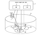
- FIG. 1 shows a configuration example of a wireless communication system according to the present embodiment.
- the wireless communication system according to the present embodiment includes a first base station 1, a second base station 2, a mobile station 4, and a core network 5.
- the base stations 1 and 2 operate the first cell 10 and the second cell 20, respectively.
- the core network 5 includes a mobility management device 6 and a data relay device 7.
- the radio communication system according to the present embodiment is an LTE system will be described as an example.
- the first base station 1 is MeNB
- the second base station 2 is LPN
- the mobile station 4 is UE
- the core network 5 is Evolved Packet Core (EPC)
- the mobility management device 6 is Mobility Management Entity (MME)
- S-GW Serving Gateway
- the radio communication system applies C / U-plane split to the cells 10 and 20. That is, the LPN 2 provides the U-plane service to the UE 4 in the cell 20. In other words, the LPN 2 establishes a data radio bearer (Data Radio bearer (DRB)) with the UE 4 and transfers user data of the UE 4.
- DRB Data Radio bearer
- MeNB1 provides C-plane service in the cell 10 to UE4 that establishes DRB with LPN2.
- the MeNB 1 establishes a signaling radio bearer (Signaling Radio Bearer (SRB)) with the UE 4, RRC signaling for establishing and modifying the DRB with the LPN 2 in the cell 20, and the EPC 5 NAS message transfer between UE4 and UE4.
- SRB Signaling radio bearer
- the MeNB 1 uses the master information (for example, the system bandwidth, the number of transmission antennas, etc.) and the system information (for example, parameters related to the DRB of the cell 20) for the cell 20 of the LPN 2 as the downlink channel (for example, Physical Broadcast Channel). (PBCH) or Physical Downlink Shared Channel (PDSCH)) may be used for transmission.
- master information for example, the system bandwidth, the number of transmission antennas, etc.
- system information for example, parameters related to the DRB of the cell 20
- the downlink channel for example, Physical Broadcast Channel
- PBCH Physical Broadcast Channel
- PDSCH Physical Downlink Shared Channel
- the LPN 2 may control layer 1 (physical layer) and layer 2 (Media Access Control (MAC) sublayer and Radio Link Control (RLC) sublayer) for the data radio bearer established in itself.
- the LPN 2 uses an uplink control channel (for example, Physical Uplink Control) Channel (PUCCH)) or an uplink data channel (eg, Physical Uplink Shared Channel (PUSCH)).
- PUCCH Physical Uplink Control
- PUSCH Physical Uplink Shared Channel
- H-ARQ Hybrid Automatic Repeat Requestpe
- ACK Channel Quality Indicator
- PMI Precoding Matrix Indicator
- RI RankRaIndicator
- the LPN 2 may transmit downlink scheduling information, ACK / NACK for uplink transmission, and the like to the UE 4 using a downlink control channel (for example, Physical-Downlink-Control-Channel (PDCCH)).
- PDCH Physical-Downlink-Control-Channel
- the EPC 5 is a network managed mainly by an operator who provides mobile communication services.
- the EPC 5 includes a control plane (C-plane) function for performing UE 4 mobility management (for example, location registration, location update), bearer management (for example, bearer establishment, bearer configuration change, bearer release), MeNB1 and LPN2 It has a user plane (U-plane) function for transferring user data of UE 4 to an external network (not shown).
- MME6 is responsible for the C-plane function in EPC.
- the S-GW 7 is responsible for the U-plane function in EPC.
- the S-GW 7 is arranged at the boundary between the radio access network (Radio Access Network (RAN)) including the MeNB 1 and LPN 2 and the EPC 5.
- RAN Radio Access Network
- FIG. 2 shows a first example of a bearer architecture related to user data transfer in cell 20.
- the radio bearer has already been described. That is, MeNB1 establishes an SRB with UE4, RRC signaling for establishing and modifying DRB in cell 20, and C-plane services such as NAS message transfer between EPC5 and UE4 Is provided in cell 10. Moreover, LPN2 establishes DRB between UE4 and transmits / receives the user data of UE4 in the cell 20.
- MeNB1 establishes an SRB with UE4, RRC signaling for establishing and modifying DRB in cell 20, and C-plane services such as NAS message transfer between EPC5 and UE4 Is provided in cell 10.
- LPN2 establishes DRB between UE4 and transmits / receives the user data of UE4 in the cell 20.
- a signaling bearer with the EPC 5 (that is, an S1 signaling bearer using the S1-MME interface) is established between the MME 6 and the MeNB 1.
- MeNB1 establishes an S1 signaling bearer with MME6, and transmits / receives an S1 Application Protocol (S1-AP) message to and from MME6.
- S1-AP S1 Application Protocol
- the data bearer with the EPC 5 (that is, the S1 bearer using the S1-U interface) is established between the S-GW 7 and the LPN 2.
- LPN 2 establishes an S1 bearer with S-GW 7 and transmits / receives user data of UE 4 to / from S-GW 7.
- MeNB1 establishes a signaling bearer with LPN2.
- the signaling bearer between MeNB1 and LPN2 is established using, for example, the X2 interface.
- the X2 interface is an interface between eNBs.
- LPN2 is defined as a new node and a new interface different from the X2 interface is defined between eNB and LPN.
- the signaling bearer between MeNB1 and LPN2 may be established using this new interlace. This new interface is referred to herein as an X3 interface.
- MeNB1 uses the bearer setting information (hereinafter referred to as E-UTRAN Radio Access Bearer (E-RAB) setting information) necessary for establishing the S1 bearer with S-GW7 and the DRB with UE4 in LPN2. It is configured to transmit to LPN2 via the / X3 signaling bearer.
- E-RAB means a radio access bearer including an S1 bearer and a DRB.
- the LPN 2 does not need an S1 signaling bearer with the MME 6, and can set an S1 bearer and a DRB based on E-RAB setting information given from the MeNB1.
- the termination point of the S1 bearer (S1-U bearer) is different from the termination point of the S1 signaling bearer. That is, not MeNB1, but LPN2 terminates the S1 bearer. That is, in the architecture of FIG. 2, the C / U plane is separated not only in signaling within the RAN but also at the interface between the EPC 5 and the RAN.
- MeNB1 only needs to perform signaling for establishing DRB and S1 bearer necessary for UE4 to transmit and receive user data via cell 20 and LPN2.
- the MeNB 1 does not need to terminate an S1 bearer (that is, a GPRS Tunneling Protocol (GTP) tunnel) for the communication of the UE 4 via the cell 20, and user data between the S1 bearer and the DRB.
- GTP GPRS Tunneling Protocol
- the S1 bearer is a GTP tunnel, and user data (data packet) is encapsulated in a GTP tunnel packet transmitted / received between the S-GW 7 and the LPN 2.
- user data data packet
- a GTP tunnel packet encapsulating downlink user data reaches LPN 2 by being routed and forwarded by a router arranged between S-GW 7 and LPN 2. Therefore, in the bearer architecture of FIG. 2, GTP tunnel packets are typically transferred without going through MeNB1. In this case, since MeNB1 does not need to perform termination processing of the S1 bearer, the processing load of MeNB1 can be reduced.
- a non-optical fiber line (for example, a wireless line) can be used for the X2 / X3 interface.
- a GTP tunnel packet encapsulating user data may be transferred between S-GW 7 and LPN 2 via MeNB 1.
- the MeNB 1 functions as a router (for example, an Internet Protocol (IP) router) and only needs to route and forward the GTP tunnel packet.
- IP Internet Protocol
- the routing of GTP tunnel packets via MeNB1 can be realized by setting the routing table of S-GW 7, LPN2, and MeNB1.
- FIG. 3 shows a second example of the bearer architecture.
- MeNB1 routes and forwards the GTP tunnel packet.
- MeNB1 may have a proxy function for converting the IP address of the GTP tunnel packet.
- MeNB1 and LPN2 set up a tunnel 80 (eg, GTP tunnel) at the X2 / X3 interface.
- the MeNB 1 further encapsulates the GTP tunnel packet encapsulating user data in the S1 bearer between the S-GW 7 and the LPN 2 and transfers it using the tunnel 80.
- the tunnel 80 may not be set. That is, MeNB1 may transfer the GTP tunnel packet as it is without further encapsulating the GTP tunnel packet.
- MeNB 1 does not need to terminate the S1 bearer.
- MeNB1 should just operate
- MeNB1 can observe a GTP tunnel packet.
- MeNB1 can observe the traffic volume of the GTP tunnel packet to be transferred.
- MeNB1 can independently estimate the load of LPN2 or the load of cell 20. Therefore, the MeNB 1 of the present embodiment can determine whether the E-RAB or the cell 20 is inactivated via the LPN 2 based on the traffic volume of the GTP-Tunnel packet observed by itself, for example.
- the MeNB 1 is configured to hold the E-RAB setting information received from the MME 6 in the initial data bearer establishment procedure without destroying (releasing) the S1 bearer and DRB establishment in the LPN 2. ing.
- the MeNB 1 is configured to hold the E-RAB setting information in the MeNB 1 after the establishment of the S1 bearer and the DRB in the LPN 2 based on the E-RAB setting information.
- the MeNB 1 establishes the S1 bearer when the S1 bearer for the UE 4 and the DRB end point (end point) are changed from the LPN 2 to another base station (for example, another eNB or another LPN).
- the E-RAB setting information held in MeNB 1 may be transmitted to another base station without transmitting a request (or S1 handover request) to MME 6 again.
- MeNB1 sends an S1 bearer establishment request (or S1 handover request) to MME6.
- the S1 bearer and the DRB may be established in the MeNB 1 by reusing the E-RAB setting information held in the MeNB 1 without transmitting again.
- the said DRB may be set to the cell 10, and may be set to the cell (secondary cell) of MeNB1 different from the cell 10.
- the wireless communication system of this embodiment employs the C / U Split architecture. Therefore, MeNB1 is responsible not only for the C-Plane of MeNB1, but also for the C-Plane of the cell 20 of LPN2 arranged in the cell 10 of MeNB1. Therefore, as long as UE4 moves in cell 10, regardless of whether MeNB1, LPN2 or other LPNs in cell 10 provide DRB and S1 bearer for UE4, MeNB1 is DRB for UE4. And C-Plane of S1 bearer. Focusing on this point, the MeNB 1 of the present embodiment continuously holds the E-RAB setting information received from the MME 6 in the initial data bearer establishment procedure without discarding (releasing) it.
- MeNB1 reuses the E-RAB setting information hold
- this embodiment can abbreviate
- FIG. 4 is a block diagram showing a configuration example of MeNB1.
- the radio communication unit 11 receives an uplink signal (uplink signal) transmitted from the UE 4 via an antenna.
- the reception data processing unit 13 restores the received uplink signal.
- the obtained received data is transferred to another network node such as MME 6 or S-GW 7 via the communication unit 14.
- uplink user data received from the UE 4 in the cell 10 is transferred to the S-GW 7.
- NAS data among the control data received from the UE 4 is transferred to the MME 6.
- the reception data processing unit 13 receives control data transmitted to the LPN 2 or MME 6 from the control unit 15, and transmits this to the LPN 2 or MME 6 via the communication unit 14.
- the transmission data processing unit 12 acquires user data addressed to the UE 4 from the communication unit 14, and performs error correction coding, rate matching, interleaving, and the like to generate a transport channel. Further, the transmission data processing unit 12 adds control information to the data sequence of the transport channel to generate a transmission symbol sequence.
- the radio communication unit 11 generates a downlink signal (downlink signal) by performing each process such as carrier wave modulation, frequency conversion, and signal amplification based on the transmission symbol sequence, and transmits this to the UE 4. Further, the transmission data processing unit 12 receives the control data transmitted to the UE 4 from the control unit 15 and transmits it to the UE 4 via the wireless communication unit 11.
- the control unit 15 signals the MME 6, the LPN 2 and the UE 4 via the signaling bearer so that the UE 4 can receive or transmit user data in the cell 20 operated by the LPN 2. Specifically, the control unit 15 transmits an E-RAB or S1 bearer establishment request to the MME 6 via the S1 signaling bearer. The control unit 15 transmits E-RAB setting information necessary for establishing the S1 bearer and the DRB in the LPN 2 to the LPN 2 via the X2 / X3 signaling bearer. The control unit 15 transmits the DRB setting information necessary for establishing the DRB in the cell 20 in the UE 4 to the UE 4 via the SRB in the cell 10.
- control unit 15 is configured to hold the E-RAB setting information in the MeNB 1 after the establishment of the S1 bearer and the DRB in the LPN 2 based on the E-RAB setting information.
- the control unit 15 performs the S1 bearer.
- the E-RAB setting information held in the MeNB 1 may be transmitted to another base station without transmitting the establishment request (or S1 handover request) to the MME 6 again.
- the control unit 15 requests to establish an S1 bearer (or request for S1 handover). May be established in MeNB1 by reusing the E-RAB setting information held in MeNB1 without transmitting to MME6 again.
- the control unit 15 establishes DRB between MeNB1 or another base station and UE4.
- the DRB setting information may be generated based on the E-RAB setting information held in the MeNB1.
- the control part 15 should just transmit the produced
- control unit 15 may notify the MME 6 of the endpoint information of the S1 bearer changed from the LPN 2 to the MeNB 1 or another base station.
- the MME 6 transmits the notified endpoint information of the S1 bearer to the S-GW 7, and the Radio Access Network (RAN) side endpoint setting of the S1 bearer managed in the S-GW 7 is updated.
- RAN Radio Access Network
- control unit 15 may determine to switch the DRB and S1 bearer for UE4 from LPN2 to MeNB1 or another base station in response to the trigger notification from UE4 or LPN2.
- FIG. 5 is a block diagram showing a configuration example of LPN2.
- the functions and operations of the wireless communication unit 21, the transmission data processing unit 22, the reception data processing unit 23, and the communication unit 24 shown in FIG. 5 correspond to the corresponding elements of the base station 1 shown in FIG. The same as the unit 11, the transmission data processing unit 12, the reception data processing unit 13, and the communication unit 14.
- the control unit 25 of the LPN 2 receives the E-RAB setting information from the MeNB1 (control unit 15) via the X2 / X3 signaling bearer, and the S1 bearer with the S-GW 7 and the SRB with the UE 4 according to the E-RAB setting information. Set.
- FIG. 6 is a block diagram illustrating a configuration example of the UE 4.
- the wireless communication unit 41 can communicate with both the cell 10 and the cell 20. Further, the radio communication unit 41 may support carrier aggregation of a plurality of cells operated by different eNBs. In this case, the wireless communication unit 41 can simultaneously use the plurality of cells 10 and 20 for transmitting or receiving user data.
- the radio communication unit 41 receives a downlink signal from the eNB 1 or LPN 2 or both via the antenna.
- the reception data processing unit 42 restores the reception data from the received downlink signal and sends it to the data control unit 43.
- the data control unit 43 uses the received data according to the purpose. Also, the transmission data processing unit 44 and the wireless communication unit 41 generate an uplink signal using the transmission data supplied from the data control unit 43 and transmit the uplink signal to the eNB 1 or LPN 2 or both.
- the control unit 45 of the UE 4 controls the wireless communication unit 41 so as to establish an SRB in the cell 10 with the MeNB 1. And the control part 45 receives the DBB setting information for establishing DRB between LPN2 from MeNB1, and controls the radio
- UE4 can communicate via LPB between LPN2 based on signaling with MeNB1.
- control unit 45 establishes the DRB between MeNB1 or another base station and UE4 when the DRB and UE S1 bearer endpoint for UE4 is changed from LPN2 to MeNB1 or another base station. May be received in the SRB of the cell 10 from the MeNB1. Thereby, UE4 can change the connecting point of DRB from LPN2 to MeNB1 or another base station based on signaling with MeNB1.
- FIG. 7 is a block diagram showing a configuration example of the MME 6.
- the communication unit 61 communicates with the MeNB 1 and the S-GW 7.
- the bearer setting control unit 62 communicates with the MeNB 1 and the S-GW 7 via the communication unit 51, and controls the setting of the signaling bearer or the data bearer in these devices. Specifically, the bearer setting control unit 62 requests the S-GW 7 to set the S1 bearer in response to the data bearer (E-RAB or S1 bearer) setting request from the MeNB1, and also sets the E-RAB or S1.
- Bearer setting information that is, E-RAB setting information
- E-RAB setting information related to the bearer is transmitted to MeNB1.
- the bearer setting control unit 62 receives a message (for example, a path switch request) indicating that the end point of the S1 bearer set in the LPN 2 has been changed to the MeNB 1 or another base station from the MeNB 1, and the message In response to this, the S-GW 7 may be instructed to change the endpoint setting of the S1 bearer.
- a message for example, a path switch request
- FIG. 8 is a block diagram showing a configuration example of the S-GW 7.
- the communication unit 71 establishes an S1 bearer with the LPN 2 and transmits or receives user data to and from the LPN 2 via the S1 bearer.
- the communication unit 71 may establish an S1 bearer with the MeNB 1 in order to receive or transmit user data via the cell 10 by the UE 4.
- the communication unit 74 sets up an S5 / S8 bearer with the Packet Data Network Gateway (P-GW) in the EPC 5 and transmits / receives user data to / from other data relay apparatuses.
- P-GW Packet Data Network Gateway
- the transmission data processing unit 72 receives the downlink user data addressed to the UE 4 from the communication unit 74, and forwards the downlink user data to the S1 bearer based on the correspondence relationship between the upstream side, the S5 / S8 bearer, and the downstream S1 bearer. To do.
- the reception data processing unit 73 receives the uplink user data from the communication unit 71, and forwards the uplink user data to the S5 / S8 bearer based on the correspondence relationship between the S5 / S8 bearer and the S1 bearer.
- the bearer control unit 75 communicates with the MME 6 and sets an S1 bearer between the LPN 2 and the communication unit 71 according to the control of the MME 6.
- the bearer control unit 75 changes the setting of the RAN side end point of the S1 bearer according to the instruction from the MME6. Good.
- step S101 MeNB1 establishes S1 connection linked
- MeNB1 establishes the RRC connection with UE4 in the cell 10.
- control data is transmitted / received between UE4 and MeNB1, between MeNB1 and MME6, and between UE4 and MME6.
- step S102 MeNB1 determines the setting of the data bearer in a secondary cell (SCell). And MeNB1 transmits the establishment request
- the secondary cell means the cell 20 of LPN2.
- MeNB1 determines the setup of a secondary cell with respect to UE4. For example, MeNB1 may determine the data bearer setup in the cell 20 in response to the request from UE4 or the request from EPC5.
- MeNB1 may determine the data bearer setup in the cell 20 in response to the notification from UE4 which shows that the cell 20 can be used. Moreover, MeNB1 may determine the data bearer setup in the cell 20 according to the user data amount of UE4 in the cell 10 having increased. Moreover, MeNB1 may determine the data bearer setup in the cell 20, in order to offload the traffic of the cell 10, when the cell 10 is highly loaded. In addition, the MeNB 1 sets up a data bearer in the cell 20 according to the subscriber data of the UE 4 (for example, the category of the UE 4, contract information, etc.) received from the subscriber server (ie, “Home Subscriber Server” (HSS)) via the MME 6. May be determined.
- the subscriber server ie, “Home Subscriber Server” (HSS)
- the MME 6 starts the S1 bearer setting procedure in response to the E-RAB establishment request from the MeNB 1 (step S103). Specifically, the MME 6 requests the S-GW 7 to set up an S1 bearer with the LPN 2. The S-GW 7 sets up an S1 bearer with the LPN 2 and sends a response including the S1 bearer context (for example, the address of the S-GW 7 on the U-plane and the tunnel endpoint identifier (Tunnel Endpoint Identifier (TEID)) to the MME 6. TEID indicates an end point on the S-GW 7 side of the GTP tunnel as the S1 bearer In step S104, the MME 6 transmits E-RAB setting information including the S1 bearer context to the MeNB 1. E-RAB setting information Is transmitted using, for example, an E-RAB SETUP RESPONSE message sent from the MME 6 to the MeNB1.
- E-RAB setting information Is transmitted using, for example, an E-RAB SETUP RESPON
- MeNB1 transmits E-RAB setting information to LPN2 via the X2 / X3 signaling bearer.
- the E-RAB setting information includes S1 bearer setting information and DRB setting information.
- LPN2 sets S1 bearer and DRB according to E-RAB setting information.
- the S1 bearer setting information includes information necessary for establishing the S1 bearer with the S-GW 7.
- S1 bearer setting information is assigned to, for example, E-RAB ID, Quality Class Indicator (QCI), IP address of S-GW7, GID tunnel (S1 bearer) TEID of S-GW7, security key, and UE4 Contains at least one of Temporary Mobile Subscriber Identity (TMSI).
- the DRB setting information includes setting information necessary for establishing a DRB with UE4.
- the DRB setting information includes, for example, E-RAB ID, Quality Class Indicator (QCI), and physical layer and MAC sublayer setting information.
- MeNB1 transmits the setting information of DRB in cell 20 to UE4 using the SRB of cell 10.
- the DRB setting information is transmitted using an RRC reconfiguration (RRC Reconfiguration) message.
- UE4 sets DRB according to the setting information of DRB.
- step S107 the MeNB 1 transmits a message (CREATE BEARER RESPONSE) indicating completion of E-RAB setting to the MME 6.
- the message includes setting information on the LPN2 side regarding the S1 bearer (for example, the address and TEID of LPN2).
- the MME 6 transmits a message including the address of the LPN 2 and the TEID to the S-GW 7.
- the S-GW 7 updates the S1 bearer setting with the LPN2 address and TEID received from the MME 6.
- E-RAB via LPN 2 is set between UE 4 and S-GW 7 by the processing of steps S102 to S107 described above.
- step S108 UE4 receives or transmits user data via cell 20 and LPN2.
- the MeNB 1 keeps holding the information on the LPN 2, that is, the E-RAB setting information established in the LPN 2, without releasing it even after the E-RAB setting in the LPN 2.
- the E-RAB setting information held in MeNB1 includes the E-RAB setting information received from the MME 6 in step S104 for establishing the E-RAB.
- the E-RAB setting information held in the MeNB 1 includes, for example, at least one of E-RAB ID, QCI, IP address of S-GW7, TEID of GTP tunnel (S1 bearer), security key, and TMSI assigned to UE4. Contains one.
- FIG. 10 shows a configuration example of a wireless communication system according to the second embodiment.
- This embodiment shows the example of movement of UE4 in the cell 10 of MeNB1.
- the cell 30 of LPN2 and the cell 30 of LPN3 are densely arranged in the cell 10 so that the UE 4 moves from the cell 20 of LPN2 to the cell 30 of another LPN3.
- An example will be described.
- MeNB1 transmits E-RAB setting information held in MeNB1 to LPN3 when the endpoint of DRB and S1 bearer for UE4 is changed from LPN2 to LPN3. Since the E-RAB setting information held in MeNB 1 is reused, MeNB 1 does not need to transmit an E-RAB establishment request or a handover request for establishing E-RAB in LPN 3 to MME 6 again. For this reason, this embodiment can reduce signaling with MME6 when UE4 moves between LPNs, and reduces path switch delay (that is, switching delay time of a data bearer) when UE4 moves between LPNs. be able to.
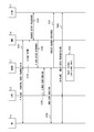
- FIG. 11 is a sequence diagram illustrating an example of a bearer switch procedure associated with movement of the UE 4 in the cell 10.
- Step S201 corresponds to step S109 shown in FIG. That is, MeNB1 holds E-RAB setting information related to E-RAB established in LPN2.
- UE4 is located in the cell 20 of LPN2. Therefore, UE4 transmits / receives control data via cell 10 and MeNB1 (step S202), and transmits / receives user data via cell 20 and LPN20 (step S203).
- MeNB1 receives a trigger notification (PATH SWITCH TRIGGER) from LPN2 or UE4.
- the trigger notification includes information for MeNB1 to determine the path switch.
- MeNB1 determines switching of the data bearer path from LPN2 to LPN3 (that is, switching of the secondary cell (SCell)) based on the trigger notification from LPN2 or UE4. Therefore, in the example of FIG. 11, LPN2 is the source LPN and LPN3 is the target LPN.
- the trigger notification from UE4 to MeNB1 may be transmitted based on the radio quality of LPN2 measured by UE4, or may indicate the radio quality.
- UE4 may transmit a trigger notification when the radio quality of LPN2 is below a predetermined threshold.
- the trigger notification from UE4 to MeNB1 may be transmitted based on the radio quality of another base station (for example, LPN3) measured by UE4, and may indicate the radio quality.
- UE4 may transmit a trigger notification when the radio quality of another base station (for example, LPN3) exceeds a predetermined threshold.
- the radio quality may be, for example, downlink received power, Signal Interference Noise Ratio (SINR), Received Signal Code Power (RSCP), or Reference Signal Received Quality (RSRQ).
- the trigger notification from LPN2 to MeNB1 may be transmitted based on load information indicating the load of LPN2, or may indicate the load information.
- LPN2 may transmit a trigger notification when the load on LPN2 exceeds a predetermined threshold.
- the load of the LPN 2 may be, for example, a radio resource usage rate (eg Physical Resource Block (PRB) usage rate) in the cell 20.
- the trigger notification from LPN2 to MeNB1 may be transmitted based on the connection state of UE4 measured in LPN2, and may indicate the connection state.
- the LPN 2 may transmit a trigger notification when the connection state of the UE 4 is deteriorated from the reference value.
- the connection state of UE 4 may be, for example, the number of occurrences or the rate of occurrence of retransmission requests from UE 4 based on Hybrid ARQ (Automatic repeat request).
- MeNB1 transmits at least a part of the stored E-RAB setting information to target LPN3.
- the target LPN 3 uses the E-RAB setting information received from the MeNB 1 to perform DRB and S1 bearer endpoint setting in the LPN 3.
- LPN3 transmits the endpoint information in LPN3 of S1 bearer for UE4 to MeNB1.
- MeNB1 updates the stored E-RAB setting information to reflect the endpoint information in LPN3 of the S1 bearer received from LPN3. In other words, MeNB1 produces
- step S207 the MeNB 1 generates DRB setting information for establishing a DRB between the UE 4 and the target LPN 3 based on the held E-RAB setting information. And MeNB1 transmits the said DRB setting information to UE4 via SRB of the cell 10.
- FIG. UE4 receives DRB setting information from MeNB1, and sets DRB in the cell 30.
- Steps S208 to S210 are S1 bearer path switching procedures, that is, procedures for switching the RAN side end point from LPN2 to LPN3.
- MeNB1 transmits the message (PATH
- the message (PATH SWITCH REQUEST) indicates that the RAN side end point of the S1 bearer for which LPN2 is set has been changed to LPN3.
- the message (PATH SWITCH REQUEST) may include, for example, an E-RAB identifier (or S1 bearer identifier), an address of LPN3, and an endpoint identifier (TEID) of the S1 bearer in LPN3.
- step S209 the MME 6 transmits an S1 bearer update request (BEARER MODIFY) to the S-GW 7.
- the S1 bearer update request includes, for example, the address of LPN 3 and the TEID.
- the S-GW 7 updates the S1 bearer setting with the LPN3 address and TEID received from the MME 6.
- step S210 the MME 6 transmits a message (PATH SWITCH RESPONSE) indicating completion of the route switching of the S1 bearer to the MeNB1.
- the E-RAB that passes through the LPN 3 is set between the UE 4 and the S-GW 7 by the processing of the above steps S210 to S211.
- UE4 transmits / receives control data via the cell 10 and MeNB1 similarly to when communicating with LPN2 (step S202).
- UE4 receives or transmits user data via cell 30 and LPN3.
- FIG. 12 is a flowchart illustrating an operation example of the MeNB 1.
- MeNB1 control part 15 determines whether the secondary cell of UE4 set to LPN2 is switched to another LPN (here LPN3).
- LPN3 another LPN
- the MeNB 1 determines whether the E-RAB setting information is already held (step S302).
- the MeNB 1 executes a normal bearer setting procedure (for example, a handover procedure), and switches the data bearer for the UE 4 from LPN2 to LPN3 (step S303).
- a normal bearer setting procedure for example, a handover procedure
- the MeNB 1 executes the processes after step S304.
- step S304 the MeNB 1 notifies the target LPN 3 of E-RAB setting information based on the held E-RAB setting information (that is, E-RAB setting information related to the LPN 2).
- step S305 MeNB1 determines whether the E-RAB setting completion notification has been received from the target LPN3.
- the MeNB 1 generates DRB setting information reflecting the DRB setting in the LPN 3, and transmits this to the UE 4 (step S306).
- step S307 MeNB1 determines whether the DRB setting completion notification was received from UE4.
- Step S307 the MeNB 1 transmits a path switch request (that is, an S1 bearer route switching request) to the MME 6 (Step S308). And MeNB1 completes the process of FIG. 12, when a path switch completion notification is received from MME6 (step S309).
- a path switch completion notification is received from MME6 (step S309).
- FIG. 13 is a flowchart showing an operation example of LPNs 2 and 3. The following description will be given with respect to LPN2, but the operation of LPN3 is the same as that of LPN2.
- LPN2 (control part 25) determines whether E-RAB setting information was received from MeNB1.
- the LPN 2 sets the S1 bearer with the S-GW 7 and the DRB with the UE 4 according to the E-RAB setting information (Steps S402 and S402). S403).
- step S404 LPN2 notifies MeNB1 of completion of E-RAB setting.
- FIG. 14 is a flowchart showing an operation example of UE4.
- UE4 (control part 45) receives DRB setting information from MeNB1.
- UE4 sets DRB (For example, DRB with LPN2 in the cell 20, or DRB with LPN3 in the cell 30) according to DRB setting information.
- FIG. 15 is a flowchart showing an operation example of the MME 6.
- the MME 6 (bearer setting control unit 62) determines whether a path switch request is received from the MeNB1.
- the MME 6 transmits an S1 bearer route change request (bearer update request (BEARER MODIFY)) to the S-GW 7 (step S602).
- the MME 6 determines whether or not the S1 bearer path change completion notification has been received from the S-GW 7.
- the MME 6 notifies the MeNB 1 of the completion of the path switch (completion of the route switching of the S1 bearer) (step S604).
- FIG. 16 is a flowchart showing an operation example of the S-GW 7.
- the S-GW 7 (bearer control unit 75) determines whether an S1 bearer route change request (bearer update request) has been received from the MME 6.
- the route change request of the S1 bearer indicates that the endpoint on the RAN side of the S1 bearer for UE4 is changed from LPN2 to LPN3.
- the S-GW 7 updates the setting of the S1 bearer for the UE 4 according to the S1 bearer setting information (step S702). That is, the S-GW 7 changes the RAN side endpoint of the S1 bearer for the UE 4 to LPN3.
- the S-GW 7 notifies the MME 6 of the route change completion (update completion) of the S1 bearer.
- FIG. 17 illustrates a configuration example of a wireless communication system according to the third embodiment.
- This embodiment shows the example of movement of UE4 in the cell 10 of MeNB1.
- at least one LPN including LPN2 is sparsely arranged in the MeNB cell 10, and the LPN cell 20 overlaps with other LPN cells (for example, LPN cell 30). Absent. Therefore, this embodiment demonstrates the example which changes the data bearer path
- the MeNB1 when the end point of the DRB and S1 bearer for UE4 is changed from LPN2 to MeNB1, the MeNB1 reuses the E-RAB setting information held in the MeNB1 to reconfigure the S1 bearer and the DRB. Is established in MeNB1. Since the E-RAB setting information held in MeNB1 is reused, MeNB1 does not need to transmit an E-RAB establishment request or a handover request for establishing E-RAB in MeNB1 to MME6 again. For this reason, this embodiment can reduce signaling with MME6 when UE4 moves from LPN2 to MeNB1, and reduces path switch delay (that is, switching delay time of data bearer) when UE4 moves between cells. can do.
- the said DRB when establishing DRB for UE4 in MeNB1, the said DRB may be set to the cell 10, and may be set to the cell (secondary cell) of MeNB1 different from the cell 10.
- FIG. 10 When the DRB for UE4 is set in the cell 10, this cell operation form is a general form in which C-Plane and U-Plane are common.
- this cell operation mode corresponds to so-called intra-base station carrier aggregation (Intra-eNBeCarrier Aggregation).
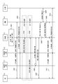
- FIG. 18 is a sequence diagram illustrating an example of a bearer switch procedure associated with movement of the UE 4 in the cell 10.
- the processes in steps S201 to S205 shown in FIG. 18 are the same as the processes in steps S201 to S205 shown in FIG. That is, MeNB1 determines switching of the data bearer path from LPN2 to MeNB1 based on the trigger notification in step S204 or S205.
- Step 806 MeNB1 reuses at least a part of the stored E-RAB configuration information, and sets S1 bearer and DRB for UE4 in MeNB1.
- the processes in steps S207 to S211 shown in FIG. 18 are the same as the processes in steps S207 to S211 shown in FIG.
- MeNB1 transmits DRB setting information for establishing DRB between UE4 and MeNB1 to UE4. Then, MeNB1 requests the MME 6 to switch the route of the S1 bearer. In step S812 of FIG. 18, UE4 receives or transmits user data via the cell 10 of MeNB1 or the cell of another MeNB1.
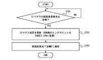
- FIG. 19 is a flowchart showing an operation example of the MeNB 1 according to the present embodiment.
- MeNB1 control part 15 determines whether the secondary cell of UE4 set to LPN2 is switched to MeNB1.
- the processes in steps S302 and S303 shown in FIG. 19 are the same as the processes in steps S302 and S303 shown in FIG. 12 except that the secondary cell switching destination is MeNB1 instead of LPN3.
- MeNB1 reuses the held E-RAB setting information (that is, E-RAB setting information related to LPN2), and sets the S1 bearer and DRB for UE4 in MeNB1.
- E-RAB setting information that is, E-RAB setting information related to LPN2
- the processes in steps S305 to S309 shown in FIG. 19 are the same as the processes in steps S305 to S309 shown in FIG. 12 except that the secondary cell switching destination is MeNB1 instead of LPN3.
- FIG. 20 illustrates a configuration example of a wireless communication system according to the fourth embodiment.
- This embodiment shows a modification of the above-described second embodiment.
- MeNB1 notifies E-RAB setting information in advance to a plurality of candidate LPNs 3A and 3B before determining to switch the DRB and S1 bearer for UE4 from LPN2 to another LPN. .
- the MeNB 1 instructs the LPN (LPN 3A) to start the data bearer.
- LPN 3A the bearer switching destination LPN
- candidate LPN can perform in advance at least one part of the setting regarding S1 bearer and DRB for UE4 using the E-RAB setting information received from MeNB1. Therefore, this embodiment can further reduce the path switch delay (that is, the data bearer switching delay time) when the UE 4 moves between cells.
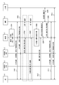
- FIG. 21 is a sequence diagram illustrating an example of a bearer switch procedure associated with movement of the UE 4 in the cell 10.
- the processing in steps S201 to S203 shown in FIG. 21 is the same as the processing in steps S201 to S203 shown in FIG.
- MeNB1 transmits the held E-RAB setting information to a plurality of candidate LPNs 3A and 3B.
- the processing in step S1005 is the same as steps S204 and S205 in FIG. That is, MeNB1 receives a trigger notification from LPN2 or UE4.
- MeNB1 determines a target LPN from among a plurality of candidate LPN3.
- the target LPN is a switching destination of the endpoint of the S1 bearer and DRB for UE4 established in LPN2 (source LPN).
- MeNB1 should just select candidate LPN which satisfies predetermined conditions among several candidate LPN as target LPN.
- the predetermined condition relates to, for example, at least one of (a) radio quality of each candidate LPN measured by the UE 4, (b) load of each candidate LPN, and (c) a moving speed of the UE 4.
- MeNB1 may receive the radio quality information of each candidate LPN or the load information of each candidate LPN from each candidate base station.
- MeNB1 may receive the radio quality information of each candidate LPN from UE4.
- the MeNB 1 may collect load information of each candidate LPN and select a candidate LPN whose load is lower than a predetermined threshold as the target LPN.
- the MeNB 1 may collect radio quality information of each candidate LPN and select a candidate LPN whose radio quality exceeds a predetermined threshold as the target LPN.
- step S1007 the MeNB 1 notifies bearer activation information to the target LPN selected from the plurality of candidate LPNs (E-RAB ACTIVATION).
- LPN 3A is selected as the target LPN.
- LPN 3A sets DRB for UE 4 in cell 30A in response to receiving bearer activation information.
- the processes in S207 to S211 shown in FIG. 21 are the same as the processes in steps S207 to S211 shown in FIG.
- FIG. 22 is a flowchart showing an operation example of the MeNB 1 according to the present embodiment.
- MeNB1 control part 15
- step S1101 MeNB1 (control part 15) notifies E-RAB setting information regarding E-RAB set to LPN2 to the candidate LPN in advance.
- the processing in steps S301 to S303 shown in FIG. 22 is the same as the processing in steps S301 to S303 shown in FIG.
- step S1104 MeNB 1 selects a target LPN from a plurality of candidate LPNs.
- MeNB 1 transmits E-RAB activation information to the target LPN.
- the processes in steps S306 to S309 shown in FIG. 22 are the same as the processes in steps S306 to S309 shown in FIG.
- FIG. 23 is a flowchart showing an operation example of a candidate LPN according to the present embodiment, that is, LPN 3A (or 3B).
- LPN 3A receives E-RAB setting information from MeNB1 in advance, and sets an S1 bearer with S-GW 7 in advance.
- LPN 3A determines whether E-RAB activation information is received from MeNB1.
- the processes in steps S403 and S404 shown in FIG. 23 are the same as the processes in steps S403 and S404 shown in FIG. That is, when E-RAB activation information is received (YES in step S1202), LPN 3A sets DRB with UE 4 in cell 30A (step S403). And LPN3A notifies MeNB1 of completion of E-RAB setting.
- MeNB1 may determine whether the change destination of the endpoint of S1 bearer and DRB for UE4 is MeNB1 or LPN3 based on the moving speed of UE4 or the inter-cell movement frequency.
- MeNB1 is good also considering MeNB1 as the change destination of the bearer endpoint for UE4, when the moving speed of UE4 or the movement frequency between cells exceeds a predetermined threshold value. Thereby, it is possible to suppress the occurrence of bearer route change processing due to the UE 4 frequently moving between a plurality of LPNs.
- MeNB1 is good also considering LPN3 as the change destination of the bearer endpoint for UE4, when the moving speed of UE4 or the movement frequency between cells is less than a predetermined threshold value.
- the communication control methods in the C / U-plane split scenario by MeNB1, LPN2, LPN3, UE4, MME6, and S-GW7 described in the first to fourth embodiments all include Application ⁇ ⁇ Specific Integrated Circuit (ASIC).
- ASIC Application ⁇ ⁇ Specific Integrated Circuit
- these methods may be realized by causing a computer system including at least one processor (e.g., microprocessor, Micro Processing Unit (MPU), Digital Signal Processor (DSP)) to execute a program.
- MPU Micro Processing Unit
- DSP Digital Signal Processor
- one or a plurality of programs including a group of instructions for causing a computer system to execute the algorithm shown in the flowchart and the sequence diagram may be created and the programs may be supplied to the computer.
- Non-transitory computer readable media include various types of tangible storage media (tangible storage medium). Examples of non-transitory computer-readable media include magnetic recording media (eg flexible disks, magnetic tapes, hard disk drives), magneto-optical recording media (eg magneto-optical discs), CD-ROMs (Read Only Memory), CD-Rs, CD-R / W, semiconductor memory (for example, mask ROM, PROM (Programmable ROM), EPROM (Erasable ROM), flash ROM, RAM (random access memory)) are included.
- the program may also be supplied to the computer by various types of temporary computer-readable media. Examples of transitory computer readable media include electrical signals, optical signals, and electromagnetic waves.
- the temporary computer-readable medium can supply the program to the computer via a wired communication path such as an electric wire and an optical fiber, or a wireless communication path.
- LTE Long Term Evolution
- 3GPP UMTS Universal Mobile Telecommunications System
- 3GPP2 CDMA2000 system (1xRTT 3GPP2 CDMA2000 system (1xRTT
- HRPD High Rate Packet Data
- GSM Global System for Mobile Communications
- Base station 2 Base station (LPN) 3, 3A, 3B Base Station (LPN) 4 Mobile station (UE) 5 Core network (EPC) 6 Mobility management device (MME) 7 Data relay device (S-GW) 15 Control unit 25 Control unit 45 Control unit 62 Bearer setting control unit 75 Bearer control unit 80 Tunnel
Abstract
Description
(a)コアネットワーク内のモビリティ管理装置との間に第1のシグナリングベアラを確立し、第2のセルを運用する第2の基地局との間に第2のシグナリングベアラを確立し、前記第1のセルにおいて移動局との間にシグナリング無線ベアラを確立するよう制御すること、
(b)データベアラ及びデータ無線ベアラを前記第2の基地局において確立するために必要な第1の設定情報を前記第2のシグナリングベアラを介して前記第2の基地局に送信すること、及び
(c)前記第2の基地局における前記データベアラ及び前記データ無線ベアラの確立後も引き続き、前記第1の基地局において前記第1の設定情報を保持すること。
ここで、前記データベアラは、前記コアネットワーク内のデータ中継装置と前記第2の基地局の間に確立される。前記データ無線ベアラは、前記第2のセルにおいて前記第2の基地局と前記移動局の間に確立される。 In the fourth aspect, the communication control method in the first base station that operates the first cell includes the following (a) to (c).
(A) establishing a first signaling bearer with a mobility management device in a core network, establishing a second signaling bearer with a second base station operating a second cell, and Controlling to establish a signaling radio bearer with a mobile station in one cell;
(B) transmitting first configuration information required to establish a data bearer and a data radio bearer in the second base station to the second base station via the second signaling bearer; and (C) The first setting information is retained in the first base station after the establishment of the data bearer and the data radio bearer in the second base station.
Here, the data bearer is established between the data relay apparatus in the core network and the second base station. The data radio bearer is established between the second base station and the mobile station in the second cell.
図1は、本実施形態に係る無線通信システムの構成例を示している。本実施形態に係る無線通信システムは、第1の基地局1、第2の基地局2、移動局4、及びコアネットワーク5を含む。基地局1及び2は、第1のセル10及び第2のセル20をそれぞれ運用する。コアネットワーク5は、モビリティ管理装置6及びデータ中継装置7を含む。以下では、説明の容易化のために、本実施形態に係る無線通信システムがLTEシステムである場合を例に説明する。従って、第1の基地局1はMeNB、第2の基地局2はLPN、移動局4はUE、コアネットワーク5はEvolved Packet Core (EPC)、モビリティ管理装置6はMobility Management Entity (MME)、データ中継装置7はServing Gateway (S-GW) に相当する。 <First Embodiment>
FIG. 1 shows a configuration example of a wireless communication system according to the present embodiment. The wireless communication system according to the present embodiment includes a first base station 1, a
図10は、第2の実施形態に係る無線通信システムの構成例を示している。本実施形態は、MeNB1のセル10内におけるUE4の移動の例を示す。具体的には、本実施形態では、セル10内にLPN2のセル30とLPN3のセル30がオーバーラップして密に配置されており、UE4がLPN2のセル20から他のLPN3のセル30に移動する例について説明する。 <Second Embodiment>
FIG. 10 shows a configuration example of a wireless communication system according to the second embodiment. This embodiment shows the example of movement of UE4 in the
また、LPN2からMeNB1へのトリガー通知は、LPN2において測定されたUE4の接続状態に基づいて送信されてもよいし、その接続状態を示してもよい。LPN2は、UE4の接続状態が基準値よりも劣化した場合にトリガー通知を送信してもよい。UE4の接続状態は、例えば、Hybrid ARQ(Automatic repeat request)に基づくUE4からの再送要求の発生数又は発生率であってもよい。 On the other hand, the trigger notification from LPN2 to MeNB1 may be transmitted based on load information indicating the load of LPN2, or may indicate the load information. LPN2 may transmit a trigger notification when the load on LPN2 exceeds a predetermined threshold. The load of the
Moreover, the trigger notification from LPN2 to MeNB1 may be transmitted based on the connection state of UE4 measured in LPN2, and may indicate the connection state. The
図17は、第3の実施形態に係る無線通信システムの構成例を示している。本実施形態は、MeNB1のセル10内におけるUE4の移動の例を示す。具体的には、本実施形態では、LPN2を含む少なくとも1つのLPNがMeNBセル10内に疎らに配置されており、LPNセル20は他のLPNセル(例えば、LPNセル30)とオーバーラップしていない。したがって、本実施形態では、UE4のためのデータベアラ経路をLPN2経由からMeNB1経由に変更する例について説明する。 <Third Embodiment>
FIG. 17 illustrates a configuration example of a wireless communication system according to the third embodiment. This embodiment shows the example of movement of UE4 in the
図20は、第4の実施形態に係る無線通信システムの構成例を示している。本実施形態は、上述した第2の実施形態の変形例を示す。具体的には、本実施形態では、LPN2において確立されたUE4のためのDRB及びS1ベアラの切り替え先となることが可能な複数の候補LPN3A及び3Bが存在する。MeNB1は、UE4のためのDRB及びS1ベアラをLPN2から他のLPNに切り替えることを決定するよりも前に、予め複数の候補LPN3A及び3Bに対して、E-RAB設定情報を予め通知しておく。そして、MeNB1は、ベアラ切り替え先LPN(例えばLPN3A)を決定した後に、そのLPN(LPN3A)に対してデータベアラの起動を指示する。これにより、候補LPNは、MeNB1から受信したE-RAB設定情報を使用して、UE4のためのS1ベアラ及びDRBに関する設定の少なくとも一部を事前に行なっておくことができる。したがって、本実施形態は、UE4がセル間を移動する際のパススイッチ遅延(つまり、データベアラの切り替え遅延時間)をいっそう低減することができる。 <Fourth Embodiment>
FIG. 20 illustrates a configuration example of a wireless communication system according to the fourth embodiment. This embodiment shows a modification of the above-described second embodiment. Specifically, in the present embodiment, there are a plurality of
上述した第1~第4の実施形態は適宜組み合わせて実施されてもよい。例えば、第2及び第3の実施形態を組み合わせることができ、また第3及び第4の実施形態を組み合わせることもできる。この場合、MeNB1は、UE4の移動速度、又はセル間移動頻度に基づいて、UE4のためのS1ベアラ及びDRBのエンドポイントの変更先をMeNB1とするかLPN3とするかを決定してもよい。例えば、MeNB1は、UE4の移動速度またはセル間移動頻度が所定の閾値を超える場合に、UE4のためのベアラエンドポイントの変更先をMeNB1としてもよい。これにより、UE4が複数のLPNの間を頻繁に移動することに起因するベアラ経路変更処理の多発を抑制できる。反対に、MeNB1は、UE4の移動速度またはセル間移動頻度が所定の閾値を下回る場合に、UE4のためのベアラエンドポイントの変更先をLPN3としてもよい。 <Other embodiments>
The first to fourth embodiments described above may be implemented in combination as appropriate. For example, the second and third embodiments can be combined, and the third and fourth embodiments can be combined. In this case, MeNB1 may determine whether the change destination of the endpoint of S1 bearer and DRB for UE4 is MeNB1 or LPN3 based on the moving speed of UE4 or the inter-cell movement frequency. For example, MeNB1 is good also considering MeNB1 as the change destination of the bearer endpoint for UE4, when the moving speed of UE4 or the movement frequency between cells exceeds a predetermined threshold value. Thereby, it is possible to suppress the occurrence of bearer route change processing due to the
2 基地局(LPN)
3、3A、3B 基地局(LPN)
4 移動局(UE)
5 コアネットワーク(EPC)
6 モビリティ管理装置(MME)
7 データ中継装置(S-GW)
15 制御部
25 制御部
45 制御部
62 ベアラ設定制御部
75 ベアラ制御部
80 トンネル 1 Base station (MeNB)
2 Base station (LPN)
3, 3A, 3B Base Station (LPN)
4 Mobile station (UE)
5 Core network (EPC)
6 Mobility management device (MME)
7 Data relay device (S-GW)
15
Claims (45)
- 第1のセルを運用する第1の基地局と、
第2のセルを運用する第2の基地局と、
モビリティ管理装置およびデータ中継装置を含むコアネットワークと、
移動局と、
を備え、
前記第1の基地局は、前記モビリティ管理装置との間に第1のシグナリングベアラを確立し、前記第2の基地局との間に第2のシグナリングベアラを確立し、前記第1のセルにおいて前記移動局との間にシグナリング無線ベアラを確立するよう構成され、
前記第2の基地局は、前記第1の基地局との間に前記第2のシグナリングベアラを確立し、前記データ中継装置との間にデータベアラを確立し、前記第2のセルにおいて前記移動局との間にデータ無線ベアラを確立するよう構成され、
前記第1の基地局は、さらに、
前記データベアラ及び前記データ無線ベアラを前記第2の基地局において確立するために必要な第1の設定情報を、前記第2のシグナリングベアラを介して前記第2の基地局に送信するよう構成されるとともに、
前記第2の基地局における前記データベアラ及び前記データ無線ベアラの確立後も引き続き、前記第1の基地局において前記第1の設定情報を保持するよう構成されている、
無線通信システム。 A first base station operating a first cell;
A second base station operating a second cell;
A core network including a mobility management device and a data relay device;
A mobile station,
With
The first base station establishes a first signaling bearer with the mobility management device, establishes a second signaling bearer with the second base station, and in the first cell Configured to establish a signaling radio bearer with the mobile station;
The second base station establishes the second signaling bearer with the first base station, establishes a data bearer with the data relay device, and moves the mobile station in the second cell. Configured to establish a data radio bearer with the station,
The first base station further includes:
First configuration information required to establish the data bearer and the data radio bearer at the second base station is configured to be transmitted to the second base station via the second signaling bearer. And
Continuing after the establishment of the data bearer and the data radio bearer in the second base station, the first base station is configured to hold the first setting information,
Wireless communication system. - 前記第1の基地局は、前記データベアラ及び前記データ無線ベアラのエンドポイントが前記第2の基地局から第3の基地局に変更される際に、前記第1の基地局において保持されていた前記第1の設定情報を前記第3の基地局に送信する、請求項1に記載の無線通信システム。 The first base station was held in the first base station when the endpoints of the data bearer and the data radio bearer were changed from the second base station to a third base station The wireless communication system according to claim 1, wherein the first setting information is transmitted to the third base station.
- 前記第1の基地局は、
前記第2の基地局における前記データベアラ及び前記データ無線ベアラの確立の際に、前記第1の基地局から前記モビリティ管理装置への前記データベアラの確立要求に応答して、前記モビリティ管理装置から前記第1の設定情報を受信し、
前記データベアラ及び前記データ無線ベアラのエンドポイントが前記第2の基地局から前記第3の基地局に変更される際に、前記データベアラの確立要求を前記モビリティ管理装置に送信すること無く、前記第1の基地局において保持されていた前記第1の設定情報を前記第3の基地局に送信する、
請求項2に記載の無線通信システム。 The first base station is
Upon establishment of the data bearer and the data radio bearer in the second base station, in response to the data bearer establishment request from the first base station to the mobility management device, from the mobility management device Receiving the first setting information;
When the endpoint of the data bearer and the data radio bearer is changed from the second base station to the third base station, without transmitting the data bearer establishment request to the mobility management device, the Transmitting the first setting information held in the first base station to the third base station;
The wireless communication system according to claim 2. - 前記第1の基地局は、前記第3の基地局に変更された前記データベアラの前記第3の基地局におけるエンドポイント情報を前記モビリティ管理装置に通知する、請求項2又は3に記載の無線通信システム。 The radio according to claim 2 or 3, wherein the first base station notifies the mobility management device of endpoint information of the data bearer changed to the third base station in the third base station. Communications system.
- 前記第1の基地局は、前記第3の基地局の情報を用いて前記第1の設定情報を更新することにより生成された第2の設定情報を、前記データベアラ及び前記データ無線ベアラのエンドポイントが前記第3の基地局に変更された後に引き続き保持する、請求項2~4のいずれか1項に記載の無線通信システム。 The first base station uses the information of the third base station to update the first setting information, and transmits the second setting information to the end of the data bearer and the data radio bearer. The wireless communication system according to any one of claims 2 to 4, wherein the wireless communication system continues to be held after the point is changed to the third base station.
- 前記第1の基地局は、前記第3の基地局に変更された前記データベアラの前記第3の基地局におけるエンドポイント情報を前記第3の基地局から受信する、請求項2~5のいずれか1項に記載の無線通信システム。 The first base station receives end point information of the data bearer changed to the third base station in the third base station from the third base station. A wireless communication system according to claim 1.
- 前記第1の基地局は、前記データベアラ及び前記データ無線ベアラのエンドポイントを前記第2の基地局から前記第3の基地局に変更する際に、前記移動局と前記第3の基地局の間に前記データ無線ベアラを確立するための第3の設定情報を前記第1の設定情報に基づいて生成し、前記第3の設定情報を前記シグナリング無線ベアラを介して前記移動局に送信する、請求項2~6のいずれか1項に記載の無線通信システム。 When the first base station changes the endpoints of the data bearer and the data radio bearer from the second base station to the third base station, the first base station Generating the third setting information for establishing the data radio bearer between them based on the first setting information, and transmitting the third setting information to the mobile station via the signaling radio bearer, The wireless communication system according to any one of claims 2 to 6.
- 前記第1の基地局は、
前記データベアラ及び前記データ無線ベアラの変更先として前記第3の基地局を選択するのに先立って、前記第3の基地局を含む複数の候補基地局に対して前記第1の設定情報を送信しておき、
前記第3の基地局の選択後に、前記第3の基地局に対して前記データベアラの起動を指示する、
請求項2~7のいずれか1項に記載の無線通信システム。 The first base station is
Prior to selecting the third base station as the change destination of the data bearer and the data radio bearer, the first setting information is transmitted to a plurality of candidate base stations including the third base station. Aside,
Instructing the third base station to start the data bearer after selecting the third base station;
The wireless communication system according to any one of claims 2 to 7. - 前記第1の基地局は、前記複数の候補基地局のうち所定の条件を満足する候補基地局を前記第3の基地局として選択する、請求項8に記載の無線通信システム。 The wireless communication system according to claim 8, wherein the first base station selects, as the third base station, a candidate base station that satisfies a predetermined condition among the plurality of candidate base stations.
- 前記所定の条件は、(a)移動局によって測定された各候補基地局の無線品質、(b)各候補基地局の負荷、及び(c)前記移動局の移動速度、のうち少なくとも1つに関する、請求項9に記載の無線通信システム。 The predetermined condition relates to at least one of (a) radio quality of each candidate base station measured by the mobile station, (b) load of each candidate base station, and (c) a moving speed of the mobile station. The wireless communication system according to claim 9.
- 前記第1の基地局は、前記無線品質および前記負荷の少なくとも一方を各候補基地局から受信する、請求項10に記載の無線通信システム。 The wireless communication system according to claim 10, wherein the first base station receives at least one of the wireless quality and the load from each candidate base station.
- 前記第1の基地局は、前記データベアラ及び前記データ無線ベアラのエンドポイントが前記第2の基地局から前記第1の基地局に変更される際に、前記第1の基地局において保持されていた前記第1の設定情報を再利用して前記データベアラ及び前記データ無線ベアラを前記第1の基地局において確立する、請求項1~11のいずれか1項に記載の無線通信システム。 The first base station is held in the first base station when endpoints of the data bearer and the data radio bearer are changed from the second base station to the first base station. The radio communication system according to any one of claims 1 to 11, wherein the first setting information is reused to establish the data bearer and the data radio bearer in the first base station.
- 前記第1の基地局は、
前記第2の基地局における前記データベアラ及び前記データ無線ベアラの確立の際に、前記第1の基地局から前記モビリティ管理装置への前記データベアラの確立要求に応答して、前記モビリティ管理装置から前記第1の設定情報を受信し、
前記データベアラ及び前記データ無線ベアラのエンドポイントが前記第2の基地局から前記第1の基地局に変更される際に、前記データベアラの確立要求を前記モビリティ管理装置に送信すること無く、前記第1の基地局において保持されていた前記第1の設定情報を用いて前記データベアラ及び前記データ無線ベアラを前記第1の基地局において確立する、
請求項12に記載の無線通信システム。 The first base station is
Upon establishment of the data bearer and the data radio bearer in the second base station, in response to the data bearer establishment request from the first base station to the mobility management device, from the mobility management device Receiving the first setting information;
When the endpoint of the data bearer and the data radio bearer is changed from the second base station to the first base station, without transmitting the data bearer establishment request to the mobility management device, the Establishing the data bearer and the data radio bearer at the first base station using the first configuration information held at the first base station;
The wireless communication system according to claim 12. - 前記第1の基地局は、前記移動局の移動速度に基づいて、前記データベアラ及び前記データ無線ベアラのエンドポイントの変更先を前記第1の基地局とするか又は他の基地局とするかを決定する、請求項12又は13に記載の無線通信システム。 Whether the first base station changes the endpoint of the data bearer and the data radio bearer to the first base station or another base station based on the moving speed of the mobile station The wireless communication system according to claim 12, wherein the wireless communication system is determined.
- 前記第1の基地局は、前記移動局又は前記第2の基地局からのトリガー通知に応答して、前記データベアラ及び前記データ無線ベアラのエンドポイントの変更を決定する、請求項1~14のいずれか1項に記載の無線通信システム。 The first base station determines an end point change of the data bearer and the data radio bearer in response to a trigger notification from the mobile station or the second base station. The wireless communication system according to any one of the above.
- 前記移動局は、前記第2の基地局との間にシグナリング無線ベアラを確立すること無く、前記データ無線ベアラを介してユーザーデータを送信又は受信するよう構成されている、請求項1~15のいずれかに記載の無線通信システム。 The mobile station according to claim 1 to 15, wherein the mobile station is configured to transmit or receive user data via the data radio bearer without establishing a signaling radio bearer with the second base station. The radio | wireless communications system in any one.
- 非アクセス層制御メッセージは、前記第1のシグナリングベアラ及び前記シグナリング無線ベアラを経由して、前記コアネットワークと前記移動局の間で転送される、請求項1~16のいずれか1項に記載の無線通信システム。 The non-access layer control message is transferred between the core network and the mobile station via the first signaling bearer and the signaling radio bearer. Wireless communication system.
- 前記第1の設定情報は、前記データベアラの識別子、前記データベアラのQoS情報、前記データ中継装置のアドレス、前記データ中継装置のトンネルエンドポイント識別子、及び前記移動局の識別子、のうち少なくとも1つを含む、請求項1~17のいずれか1項に記載の無線通信システム。 The first setting information includes at least one of an identifier of the data bearer, QoS information of the data bearer, an address of the data relay device, a tunnel endpoint identifier of the data relay device, and an identifier of the mobile station. The wireless communication system according to any one of claims 1 to 17, further comprising:
- 第1のセルを運用する無線通信手段と、
制御手段と、
を備え、
前記制御手段は、
コアネットワーク内のモビリティ管理装置との間に第1のシグナリングベアラを確立し、第2のセルを運用する第2の基地局との間に第2のシグナリングベアラを確立し、前記第1のセルにおいて移動局との間にシグナリング無線ベアラを確立するよう制御し、
データベアラ及びデータ無線ベアラを前記第2の基地局において確立するために必要な第1の設定情報を前記第2のシグナリングベアラを介して前記第2の基地局に送信し、
前記第2の基地局における前記データベアラ及び前記データ無線ベアラの確立後も引き続き、前記第1の設定情報を保持するよう構成されており、
前記データベアラは、前記コアネットワーク内のデータ中継装置と前記第2の基地局の間に確立され、
前記データ無線ベアラは、前記第2のセルにおいて前記第2の基地局と前記移動局の間に確立される、
第1の基地局。 Wireless communication means for operating the first cell;
Control means;
With
The control means includes
A first signaling bearer is established with a mobility management device in a core network, a second signaling bearer is established with a second base station that operates a second cell, and the first cell Control to establish a signaling radio bearer with the mobile station at
Transmitting first configuration information required to establish a data bearer and a data radio bearer in the second base station to the second base station via the second signaling bearer;
Continuing after the establishment of the data bearer and the data radio bearer in the second base station is configured to hold the first setting information,
The data bearer is established between a data relay device in the core network and the second base station,
The data radio bearer is established between the second base station and the mobile station in the second cell;
First base station. - 前記制御手段は、前記データベアラ及び前記データ無線ベアラのエンドポイントが前記第2の基地局から第3の基地局に変更される際に、前記第1の基地局において保持されていた前記第1の設定情報を前記第3の基地局に送信する、請求項19に記載の第1の基地局。 The control means is configured to maintain the first bearer in the first base station when the end points of the data bearer and the data radio bearer are changed from the second base station to a third base station. The first base station according to claim 19, wherein the setting information is transmitted to the third base station.
- 前記制御手段は、
前記第2の基地局における前記データベアラ及び前記データ無線ベアラの確立の際に、前記第1の基地局から前記モビリティ管理装置への前記データベアラの確立要求に応答して、前記モビリティ管理装置から前記第1の設定情報を受信し、
前記データベアラ及び前記データ無線ベアラのエンドポイントが前記第2の基地局から前記第3の基地局に変更される際に、前記データベアラの確立要求を前記モビリティ管理装置に送信すること無く、前記第1の基地局において保持されていた前記第1の設定情報を前記第3の基地局に送信する、
請求項20に記載の第1の基地局。 The control means includes
Upon establishment of the data bearer and the data radio bearer in the second base station, in response to the data bearer establishment request from the first base station to the mobility management device, from the mobility management device Receiving the first setting information;
When the endpoint of the data bearer and the data radio bearer is changed from the second base station to the third base station, without transmitting the data bearer establishment request to the mobility management device, the Transmitting the first setting information held in the first base station to the third base station;
The first base station according to claim 20. - 前記制御手段は、前記第3の基地局に変更された前記データベアラの前記第3の基地局におけるエンドポイント情報を前記モビリティ管理装置に通知する、請求項20又は21に記載の第1の基地局。 The first base according to claim 20 or 21, wherein the control means notifies the mobility management device of endpoint information in the third base station of the data bearer changed to the third base station. Bureau.
- 前記制御手段は、前記第3の基地局の情報を用いて前記第1の設定情報を更新することにより生成された第2の設定情報を、前記データベアラ及び前記データ無線ベアラのエンドポイントが前記第3の基地局に変更された後に引き続き保持する、請求項20~22のいずれか1項に記載の第1の基地局。 The control means includes the second setting information generated by updating the first setting information using the information of the third base station, and the endpoints of the data bearer and the data radio bearer The first base station according to any one of claims 20 to 22, wherein the first base station continues to be held after being changed to a third base station.
- 前記制御手段は、前記第3の基地局に変更された前記データベアラの前記第3の基地局におけるエンドポイント情報を前記第3の基地局から受信する、請求項20~23のいずれか1項に記載の第1の基地局。 The control unit according to any one of claims 20 to 23, wherein the control unit receives the end point information of the data bearer changed to the third base station in the third base station from the third base station. The 1st base station of description.
- 前記制御手段は、前記データベアラ及び前記データ無線ベアラのエンドポイントを前記第2の基地局から前記第3の基地局に変更する際に、前記移動局と前記第3の基地局の間に前記データ無線ベアラを確立するための第3の設定情報を前記第1の設定情報に基づいて生成し、前記第3の設定情報を前記シグナリング無線ベアラを介して前記移動局に送信する、請求項20~24のいずれか1項に記載の第1の基地局。 The control means, when changing the endpoint of the data bearer and the data radio bearer from the second base station to the third base station, between the mobile station and the third base station, 21. Third setting information for establishing a data radio bearer is generated based on the first setting information, and the third setting information is transmitted to the mobile station via the signaling radio bearer. The first base station according to any one of 1 to 24.
- 前記制御手段は、
前記データベアラ及び前記データ無線ベアラの変更先として前記第3の基地局を選択するのに先立って、前記第3の基地局を含む複数の候補基地局に対して前記第1の設定情報を送信しておき、
前記第3の基地局の選択後に、前記第3の基地局に対して前記データベアラの起動を指示する、
請求項20~25のいずれか1項に記載の第1の基地局。 The control means includes
Prior to selecting the third base station as the change destination of the data bearer and the data radio bearer, the first setting information is transmitted to a plurality of candidate base stations including the third base station. Aside,
Instructing the third base station to start the data bearer after selecting the third base station;
The first base station according to any one of claims 20 to 25. - 前記制御手段は、前記複数の候補基地局のうち所定の条件を満足する候補基地局を前記第3の基地局として選択する、請求項26に記載の第1の基地局。 The first base station according to claim 26, wherein the control means selects, as the third base station, a candidate base station that satisfies a predetermined condition among the plurality of candidate base stations.
- 前記所定の条件は、(a)移動局によって測定された各候補基地局の無線品質、(b)各候補基地局の負荷、及び(c)前記移動局の移動速度、のうち少なくとも1つに関する、請求項27に記載の第1の基地局。 The predetermined condition relates to at least one of (a) radio quality of each candidate base station measured by the mobile station, (b) load of each candidate base station, and (c) a moving speed of the mobile station. The first base station according to claim 27.
- 前記制御手段は、前記無線品質および前記負荷の少なくとも一方を各候補基地局から受信する、請求項28に記載の第1の基地局。 29. The first base station according to claim 28, wherein the control means receives at least one of the radio quality and the load from each candidate base station.
- 前記制御手段は、前記データベアラ及び前記データ無線ベアラのエンドポイントが前記第2の基地局から前記第1の基地局に変更される際に、前記第1の基地局において保持されていた前記第1の設定情報を用いて前記データベアラ及び前記データ無線ベアラを前記第1の基地局において確立する、請求項19~29のいずれか1項に記載の第1の基地局。 The control means, when the endpoint of the data bearer and the data radio bearer is changed from the second base station to the first base station, the first base station holds the first bearer The first base station according to any one of claims 19 to 29, wherein the data bearer and the data radio bearer are established in the first base station using one setting information.
- 前記制御手段は、
前記第2の基地局における前記データベアラ及び前記データ無線ベアラの確立の際に、前記第1の基地局から前記モビリティ管理装置への前記データベアラの確立要求に応答して、前記モビリティ管理装置から前記第1の設定情報を受信し、
前記データベアラ及び前記データ無線ベアラのエンドポイントが前記第2の基地局から前記第1の基地局に変更される際に、前記データベアラの確立要求を前記モビリティ管理装置に送信すること無く、前記第1の基地局において保持されていた前記第1の設定情報を用いて前記データベアラ及び前記データ無線ベアラを前記第1の基地局において確立する、
請求項30に記載の第1の基地局。 The control means includes
Upon establishment of the data bearer and the data radio bearer in the second base station, in response to the data bearer establishment request from the first base station to the mobility management device, from the mobility management device Receiving the first setting information;
When the endpoint of the data bearer and the data radio bearer is changed from the second base station to the first base station, without transmitting the data bearer establishment request to the mobility management device, the Establishing the data bearer and the data radio bearer at the first base station using the first configuration information held at the first base station;
The first base station according to claim 30. - 前記制御手段は、前記移動局の移動速度に基づいて、前記データベアラ及び前記データ無線ベアラのエンドポイントの変更先を前記第1の基地局とするか又は他の基地局とするかを決定する、請求項30又は31に記載の第1の基地局。 The control means determines, based on the moving speed of the mobile station, whether to change the endpoint of the data bearer and the data radio bearer to the first base station or another base station. The first base station according to claim 30 or 31.
- 前記制御手段は、前記移動局又は前記第2の基地局からのトリガー通知に応答して、前記データベアラ及び前記データ無線ベアラのエンドポイントの変更を決定する、請求項19~32のいずれか1項に記載の第1の基地局。 The control means determines the change of the endpoints of the data bearer and the data radio bearer in response to a trigger notification from the mobile station or the second base station. A first base station according to Item.
- 請求項1~18のいずれか1項に記載の無線通信システムと結合して使用される移動局であって、
無線通信手段と、
前記データ無線ベアラに関する設定情報を前記第1の基地局から受信し、前記第2のセルを利用してユーザーデータを受信又は送信するよう前記無線通信手段を制御する制御手段と、
を備える、移動局。 A mobile station used in combination with the radio communication system according to any one of claims 1 to 18,
Wireless communication means;
Control means for receiving the setting information related to the data radio bearer from the first base station and controlling the radio communication means to receive or transmit user data using the second cell;
A mobile station comprising: - 前記制御手段は、前記第2の基地局との間にシグナリング無線ベアラを確立すること無く、前記データ無線ベアラを介した前記ユーザーデータの送信又は受信を制御する、請求項34に記載の移動局。 The mobile station according to claim 34, wherein the control means controls transmission or reception of the user data via the data radio bearer without establishing a signaling radio bearer with the second base station. .
- 第1のセルを運用する第1の基地局における通信制御方法であって、
コアネットワーク内のモビリティ管理装置との間に第1のシグナリングベアラを確立し、第2のセルを運用する第2の基地局との間に第2のシグナリングベアラを確立し、前記第1のセルにおいて移動局との間にシグナリング無線ベアラを確立するよう制御すること、
データベアラ及びデータ無線ベアラを前記第2の基地局において確立するために必要な第1の設定情報を前記第2のシグナリングベアラを介して前記第2の基地局に送信すること、及び
前記第2の基地局における前記データベアラ及び前記データ無線ベアラの確立後も引き続き、前記第1の基地局において前記第1の設定情報を保持すること、
を備え、
前記データベアラは、前記コアネットワーク内のデータ中継装置と前記第2の基地局の間に確立され、
前記データ無線ベアラは、前記第2のセルにおいて前記第2の基地局と前記移動局の間に確立される、
通信制御方法。 A communication control method in a first base station that operates a first cell,
A first signaling bearer is established with a mobility management device in a core network, a second signaling bearer is established with a second base station that operates a second cell, and the first cell Controlling to establish a signaling radio bearer with the mobile station at
Transmitting first configuration information required to establish a data bearer and a data radio bearer at the second base station to the second base station via the second signaling bearer; and Continuously holding the first setting information in the first base station after the establishment of the data bearer and the data radio bearer in the base station;
With
The data bearer is established between a data relay device in the core network and the second base station,
The data radio bearer is established between the second base station and the mobile station in the second cell;
Communication control method. - 前記データベアラ及び前記データ無線ベアラのエンドポイントが前記第2の基地局から第3の基地局に変更される際に、前記第1の基地局において保持されていた前記第1の設定情報を前記第3の基地局に送信することをさらに備える、請求項36に記載の方法。 When the endpoints of the data bearer and the data radio bearer are changed from the second base station to a third base station, the first setting information held in the first base station is changed to the first setting information. 40. The method of claim 36, further comprising transmitting to a third base station.
- 前記第2の基地局における前記データベアラ及び前記データ無線ベアラの確立の際に、前記第1の基地局から前記モビリティ管理装置への前記データベアラの確立要求に応答して、前記モビリティ管理装置から前記第1の設定情報を受信することをさらに備え、
前記第1の設定情報を前記第3の基地局に送信することは、前記データベアラの確立要求を前記モビリティ管理装置に送信すること無く、前記第1の基地局において保持されていた前記第1の設定情報を前記第3の基地局に送信することを含む、
請求項37に記載の方法。 Upon establishment of the data bearer and the data radio bearer in the second base station, in response to the data bearer establishment request from the first base station to the mobility management device, from the mobility management device Further comprising receiving the first setting information;
Sending the first setting information to the third base station means that the first base station holds the first setting information without sending the data bearer establishment request to the mobility management device. Transmitting the setting information to the third base station,
38. The method of claim 37. - 前記第3の基地局に変更された前記データベアラの前記第3の基地局におけるエンドポイント情報を前記モビリティ管理装置に通知することをさらに備える、請求項37又は38に記載の方法。 The method according to claim 37 or 38, further comprising notifying the mobility management device of endpoint information in the third base station of the data bearer changed to the third base station.
- 前記第1の設定情報を前記第3の基地局に送信することは、
前記データベアラ及び前記データ無線ベアラの変更先として前記第3の基地局を選択するのに先立って、前記第3の基地局を含む複数の候補基地局に対して前記第1の設定情報を送信すること、及び
前記第3の基地局の選択後に、前記第3の基地局に対して前記データベアラの起動を指示すること、
を含む、請求項37~39のいずれか1項に記載の方法。 Transmitting the first configuration information to the third base station,
Prior to selecting the third base station as the change destination of the data bearer and the data radio bearer, the first setting information is transmitted to a plurality of candidate base stations including the third base station. And, after selecting the third base station, instructing the third base station to start up the data bearer,
The method according to any one of claims 37 to 39, comprising: - 前記第1の設定情報を前記第3の基地局に送信することは、前記複数の候補基地局のうち所定の条件を満足する候補基地局を前記第3の基地局として選択することを含む、請求項40に記載の方法。 Transmitting the first setting information to the third base station includes selecting, as the third base station, a candidate base station that satisfies a predetermined condition among the plurality of candidate base stations; 41. The method of claim 40.
- 前記データベアラ及び前記データ無線ベアラのエンドポイントが前記第2の基地局から前記第1の基地局に変更される際に、前記第1の基地局において保持されていた前記第1の設定情報を用いて前記データベアラ及び前記データ無線ベアラを前記第1の基地局において確立することをさらに備える、請求項36~41のいずれか1項に記載の方法。 The first setting information held in the first base station when the endpoints of the data bearer and the data radio bearer are changed from the second base station to the first base station. The method according to any one of claims 36 to 41, further comprising using to establish the data bearer and the data radio bearer at the first base station.
- 前記第2の基地局における前記データベアラ及び前記データ無線ベアラの確立の際に、前記第1の基地局から前記モビリティ管理装置への前記データベアラの確立要求に応答して、前記モビリティ管理装置から前記第1の設定情報を受信することをさらに備え、
前記データベアラ及び前記データ無線ベアラを前記第1の基地局において確立することは、前記データベアラの確立要求を前記モビリティ管理装置に送信すること無く、前記第1の基地局において保持されていた前記第1の設定情報を用いて前記データベアラ及び前記データ無線ベアラを前記第1の基地局において設定することを含む、
請求項42に記載の方法。 Upon establishment of the data bearer and the data radio bearer in the second base station, in response to the data bearer establishment request from the first base station to the mobility management device, from the mobility management device Further comprising receiving the first setting information;
Establishing the data bearer and the data radio bearer in the first base station was not held in the first base station without transmitting the data bearer establishment request to the mobility management device. Including setting the data bearer and the data radio bearer in the first base station using first setting information,
43. The method of claim 42. - 前記移動局の移動速度に基づいて、前記データベアラ及び前記データ無線ベアラのエンドポイントの変更先を前記第1の基地局とするか又は他の基地局とするかを決定することをさらに備える、請求項42又は43に記載の方法。 Further comprising determining whether to change the endpoint of the data bearer and the data radio bearer to the first base station or another base station based on the moving speed of the mobile station, 44. A method according to claim 42 or 43.
- 第1のセルを運用する第1の基地局における通信制御方法をコンピュータに行わせるためのプログラムを格納した非一時的なコンピュータ可読媒体であって、
前記通信制御方法は、
コアネットワーク内のモビリティ管理装置との間に第1のシグナリングベアラを確立し、第2のセルを運用する第2の基地局との間に第2のシグナリングベアラを確立し、前記第1のセルにおいて移動局との間にシグナリング無線ベアラを確立するよう制御すること、
データベアラ及びデータ無線ベアラを前記第2の基地局において確立するために必要な第1の設定情報を前記第2のシグナリングベアラを介して前記第2の基地局に送信すること、及び
前記第2の基地局における前記データベアラ及び前記データ無線ベアラの確立後も引き続き、前記第1の基地局において前記第1の設定情報を保持すること、
を含み、
前記データベアラは、前記コアネットワーク内のデータ中継装置と前記第2の基地局の間に確立され、
前記データ無線ベアラは、前記第2のセルにおいて前記第2の基地局と前記移動局の間に確立される、
コンピュータ可読媒体。 A non-transitory computer-readable medium storing a program for causing a computer to perform a communication control method in a first base station that operates a first cell,
The communication control method includes:
A first signaling bearer is established with a mobility management device in a core network, a second signaling bearer is established with a second base station that operates a second cell, and the first cell Controlling to establish a signaling radio bearer with the mobile station at
Transmitting first configuration information required to establish a data bearer and a data radio bearer at the second base station to the second base station via the second signaling bearer; and Continuously holding the first setting information in the first base station after the establishment of the data bearer and the data radio bearer in the base station;
Including
The data bearer is established between a data relay device in the core network and the second base station,
The data radio bearer is established between the second base station and the mobile station in the second cell;
Computer readable medium.
Priority Applications (10)
| Application Number | Priority Date | Filing Date | Title |
|---|---|---|---|
| EP18180837.9A EP3399796B1 (en) | 2012-12-28 | 2013-08-06 | Inter-cell movement in small cell enhancement scenario |
| CN201910362073.8A CN110113766B (en) | 2012-12-28 | 2013-08-06 | Master base station and method thereof |
| ES13869592T ES2703055T3 (en) | 2012-12-28 | 2013-08-06 | Intercell movement in small cell improvement scenario |
| CN201380068880.XA CN104885517B (en) | 2012-12-28 | 2013-08-06 | Communication system, base station, movement station, control method and computer-readable medium |
| JP2014554068A JP6160630B2 (en) | 2012-12-28 | 2013-08-06 | Wireless communication system, base station, mobile station, communication control method, and program |
| EP13869592.9A EP2941050B1 (en) | 2012-12-28 | 2013-08-06 | Inter-cell movement in small cell enhancement scenario |
| CN201910359904.6A CN110225529B (en) | 2012-12-28 | 2013-08-06 | Master base station and method thereof |
| MX2015008255A MX353577B (en) | 2012-12-28 | 2013-08-06 | Radio communication system, base station, mobile station, communication control method, and computer-readable medium. |
| US14/655,842 US10440630B2 (en) | 2012-12-28 | 2013-08-06 | Radio communication system, base station, mobile station, communication control method, and computer readable medium |
| US16/513,487 US11356924B2 (en) | 2012-12-28 | 2019-07-16 | Radio communication system, base station, mobile station, communication control method, and computer readable medium |
Applications Claiming Priority (2)
| Application Number | Priority Date | Filing Date | Title |
|---|---|---|---|
| JP2012-288209 | 2012-12-28 | ||
| JP2012288209 | 2012-12-28 |
Related Child Applications (3)
| Application Number | Title | Priority Date | Filing Date |
|---|---|---|---|
| US14/655,842 A-371-Of-International US10440630B2 (en) | 2012-12-28 | 2013-08-06 | Radio communication system, base station, mobile station, communication control method, and computer readable medium |
| US201514655842A Continuation | 2012-12-28 | 2015-06-26 | |
| US16/513,487 Continuation US11356924B2 (en) | 2012-12-28 | 2019-07-16 | Radio communication system, base station, mobile station, communication control method, and computer readable medium |
Publications (1)
| Publication Number | Publication Date |
|---|---|
| WO2014103098A1 true WO2014103098A1 (en) | 2014-07-03 |
Family
ID=51020241
Family Applications (1)
| Application Number | Title | Priority Date | Filing Date |
|---|---|---|---|
| PCT/JP2013/004746 WO2014103098A1 (en) | 2012-12-28 | 2013-08-06 | Radio communication system, base station, mobile station, communication control method, and computer-readable medium |
Country Status (8)
| Country | Link |
|---|---|
| US (2) | US10440630B2 (en) |
| EP (2) | EP2941050B1 (en) |
| JP (3) | JP6160630B2 (en) |
| CN (3) | CN110113766B (en) |
| ES (1) | ES2703055T3 (en) |
| MX (1) | MX353577B (en) |
| TR (1) | TR201819072T4 (en) |
| WO (1) | WO2014103098A1 (en) |
Cited By (5)
| Publication number | Priority date | Publication date | Assignee | Title |
|---|---|---|---|---|
| WO2016056075A1 (en) * | 2014-10-08 | 2016-04-14 | 富士通株式会社 | Wireless communication system, wireless base station, mobile station, and wireless communication control method |
| CN105578513A (en) * | 2014-10-11 | 2016-05-11 | 电信科学技术研究院 | Communication method, equipment and communication system |
| JP2016534585A (en) * | 2013-09-23 | 2016-11-04 | ゼットティーイー コーポレイション | Small cell switching method, base station, and computer storage medium |
| CN107734571A (en) * | 2016-08-12 | 2018-02-23 | 电信科学技术研究院 | The processing method and equipment of a kind of data transmission channel |
| JP2020096389A (en) * | 2015-03-11 | 2020-06-18 | 日本電気株式会社 | Communication method, communication system, and mobile management device |
Families Citing this family (19)
| Publication number | Priority date | Publication date | Assignee | Title |
|---|---|---|---|---|
| EP2875673A4 (en) * | 2012-07-17 | 2016-05-11 | Nokia Technologies Oy | System and method for proactive u-plane handovers |
| CN110113766B (en) * | 2012-12-28 | 2022-09-13 | 日本电气株式会社 | Master base station and method thereof |
| US20160143015A1 (en) * | 2013-06-17 | 2016-05-19 | Nokia Solutions And Networks Oy | Cell operation concept |
| KR102287928B1 (en) | 2013-09-27 | 2021-08-10 | 삼성전자 주식회사 | Method and apparatus for transmitting and receiving a data using a plurality of carriers in mobile communication system |
| WO2015070445A1 (en) * | 2013-11-15 | 2015-05-21 | 华为技术有限公司 | Method and base station for establishing radio bearers |
| KR101994764B1 (en) | 2014-01-30 | 2019-07-01 | 닛본 덴끼 가부시끼가이샤 | Machine-to-machine(m2m) terminal, base station, method, and computer-readable medium |
| US20150271705A1 (en) * | 2014-03-18 | 2015-09-24 | Broadcom Corporation | Determining Priority Between RAN Rules and ANDSF Rules |
| US10869209B2 (en) * | 2015-10-06 | 2020-12-15 | Lg Electronics Inc. | Method and device for transmitting/receiving data to/from base station in wireless communication system |
| US20180027436A1 (en) * | 2016-07-22 | 2018-01-25 | Aruba Networks, Inc. | Radio health monitoring |
| CN108307387B (en) | 2016-09-27 | 2020-11-06 | 华为技术有限公司 | Data transmission method and device |
| WO2018066702A1 (en) * | 2016-10-07 | 2018-04-12 | 株式会社Nttドコモ | Wireless communication system, network device, and wireless communication method |
| US10341225B2 (en) * | 2016-12-30 | 2019-07-02 | Hughes Network Systems, Llc | Bonding of satellite terminals |
| WO2018126479A1 (en) * | 2017-01-09 | 2018-07-12 | 北京小米移动软件有限公司 | Method and apparatus for acquiring and sending system information |
| US11507947B1 (en) * | 2017-07-05 | 2022-11-22 | Citibank, N.A. | Systems and methods for data communication using a stateless application |
| CN108471633B (en) * | 2018-03-07 | 2020-12-04 | 北京佰才邦技术有限公司 | Communication method and communication system |
| TWI692950B (en) * | 2018-05-11 | 2020-05-01 | 瑞昱半導體股份有限公司 | Function-expandable wired network device |
| US11601841B2 (en) * | 2018-08-01 | 2023-03-07 | Nec Corporation | Radio station, radio communication method, non-transitory computer readable medium, and radio communication system |
| JP7331383B2 (en) | 2019-02-28 | 2023-08-23 | 株式会社デンソー | Rotating electric machine |
| CN113766584B (en) * | 2020-06-05 | 2022-07-19 | 大唐移动通信设备有限公司 | Method and device for processing change of auxiliary node cell |
Family Cites Families (30)
| Publication number | Priority date | Publication date | Assignee | Title |
|---|---|---|---|---|
| GB0117071D0 (en) * | 2001-07-13 | 2001-09-05 | Koninkl Philips Electronics Nv | Hierarchical cellular radio communication system |
| MX2009006070A (en) * | 2006-12-15 | 2009-07-07 | Sharp Kk | Radio communication system and radio transmission path control method. |
| JP4548851B2 (en) * | 2007-03-09 | 2010-09-22 | 株式会社エヌ・ティ・ティ・ドコモ | Mobile communication method, radio base station, and upper node |
| CA2704149C (en) * | 2007-10-30 | 2013-08-06 | Ntt Docomo Inc. | Mobile communication method and radio base station |
| JP5354642B2 (en) * | 2008-04-09 | 2013-11-27 | 日本電気株式会社 | Wireless communication system and communication method thereof |
| CN101635962B (en) * | 2008-07-24 | 2012-01-04 | 电信科学技术研究院 | Method for acquiring load situation during user-equipment switch, and MME |
| US8625582B2 (en) * | 2008-08-14 | 2014-01-07 | Motorola Solutions, Inc. | Method and apparatus for routing a bearer path in an internet protocol multimedia subsystem based communication system |
| CN101674621B (en) * | 2008-09-08 | 2012-05-23 | 中国移动通信集团公司 | Method, system and device for mobile switching |
| KR101521886B1 (en) * | 2009-01-23 | 2015-05-28 | 삼성전자주식회사 | Apparatus and method for processing gtp in mobile communication system |
| JP4910019B2 (en) | 2009-07-27 | 2012-04-04 | 三智商事株式会社 | Data writing device for wireless IC tag |
| CN102227935B (en) * | 2009-08-18 | 2014-04-02 | 华为技术有限公司 | Switch processing method, method and device for relocating terminal path |
| WO2011038352A1 (en) | 2009-09-26 | 2011-03-31 | Cisco Technology, Inc. | Providing offloads in a communication network |
| JP5274422B2 (en) * | 2009-09-29 | 2013-08-28 | 三菱電機株式会社 | Wireless communication system and handover control method |
| CN101730032A (en) * | 2010-01-18 | 2010-06-09 | 新邮通信设备有限公司 | Method for realizing data forwarding and donor base station |
| WO2011125278A1 (en) * | 2010-04-09 | 2011-10-13 | 日本電気株式会社 | Wireless communication system, communication apparatus, method for controlling simultaneous transmissions from a plurality of base stations, and noncontemporary computer readable medium |
| US9801102B2 (en) * | 2010-04-28 | 2017-10-24 | Samsung Electronics Co., Ltd. | Method and apparatus for handover using X2 interface based on closed subscriber group in mobile communication system |
| CN102238656A (en) * | 2010-04-28 | 2011-11-09 | 北京三星通信技术研究有限公司 | Switching method for mobile communication system |
| KR101724371B1 (en) * | 2010-05-28 | 2017-04-10 | 삼성전자주식회사 | Apparatus and method for supporting mobility in heterogeneous wireless communication system |
| CN102457915B (en) * | 2010-10-26 | 2016-03-02 | 株式会社Ntt都科摩 | Manage the method for X2 interface, changing method, disturbance restraining method and device |
| CN102469557B (en) * | 2010-11-15 | 2014-08-13 | 华为技术有限公司 | Method for accessing base station, base station and user equipment |
| KR20120070038A (en) * | 2010-12-21 | 2012-06-29 | 한국전자통신연구원 | Contention based uplink transmission method |
| US8982838B2 (en) * | 2011-02-11 | 2015-03-17 | Lg Electronics Inc. | Method for processing data associated with handover in a wireless network |
| JP5175973B2 (en) * | 2011-04-28 | 2013-04-03 | 株式会社エヌ・ティ・ティ・ドコモ | Mobile communication system and radio base station |
| EP2536070A1 (en) * | 2011-06-15 | 2012-12-19 | BAE Systems Plc | Data transfer |
| US8811347B2 (en) * | 2011-06-16 | 2014-08-19 | Lg Electronics Inc. | Method and apparatus for selecting MME in wireless communication system including mobile relay node |
| EP2848023A4 (en) * | 2012-05-07 | 2016-01-06 | Ericsson Telefon Ab L M | Communication apparatus and mobility method therefor |
| JP5758351B2 (en) * | 2012-06-22 | 2015-08-05 | 株式会社Nttドコモ | Wireless communication system |
| CN102833802B (en) | 2012-08-15 | 2015-09-23 | 电信科学技术研究院 | A kind of data forwarding method and equipment |
| KR101919913B1 (en) | 2012-10-05 | 2018-11-19 | 닛본 덴끼 가부시끼가이샤 | Wireless communication system, base station, mobile station, communication control method, and computer-readable medium |
| CN110113766B (en) * | 2012-12-28 | 2022-09-13 | 日本电气株式会社 | Master base station and method thereof |
-
2013
- 2013-08-06 CN CN201910362073.8A patent/CN110113766B/en active Active
- 2013-08-06 CN CN201380068880.XA patent/CN104885517B/en active Active
- 2013-08-06 CN CN201910359904.6A patent/CN110225529B/en active Active
- 2013-08-06 EP EP13869592.9A patent/EP2941050B1/en active Active
- 2013-08-06 US US14/655,842 patent/US10440630B2/en active Active
- 2013-08-06 EP EP18180837.9A patent/EP3399796B1/en active Active
- 2013-08-06 ES ES13869592T patent/ES2703055T3/en active Active
- 2013-08-06 WO PCT/JP2013/004746 patent/WO2014103098A1/en active Application Filing
- 2013-08-06 MX MX2015008255A patent/MX353577B/en active IP Right Grant
- 2013-08-06 JP JP2014554068A patent/JP6160630B2/en active Active
- 2013-08-06 TR TR2018/19072T patent/TR201819072T4/en unknown
-
2017
- 2017-06-01 JP JP2017109052A patent/JP6451783B2/en active Active
-
2018
- 2018-12-07 JP JP2018229696A patent/JP6645563B2/en active Active
-
2019
- 2019-07-16 US US16/513,487 patent/US11356924B2/en active Active
Non-Patent Citations (6)
| Title |
|---|
| "Requirements, Candidate Solutions & Technology Roadmap for LTE Rel-12 Onward", 3GPP TSG RAN WORKSHOP ON REL-12 AND ONWARDS LJUBLJANA, 11 June 2012 (2012-06-11) |
| ERICSSON: "RESPONSE DOCUMENT TO R3-100907 protocol", 3GPP R3- 101013, 18 February 2010 (2010-02-18), pages 1 - 8, XP050424801 * |
| ERICSSON: "Termination of the S1/X2 interfaces in relay node", 3GPP R2-092953, 8 April 2009 (2009-04-08), pages 1 - 4, XP050340749 * |
| NTT DOCOMO, INC.: "Requirements, Candidate Solutions & Technology Roadmap for LTE Rel-12 Onward", 3GPP RWS-120010, 11 June 2011 (2011-06-11), pages 1 - 27, XP055176152 * |
| SAMSUNG: "Add Rel-11 scenarios for HeNB mobility enhancement.", 3GPP R3-122638, 3 November 2012 (2012-11-03), pages 1 - 5, XP050670512 * |
| See also references of EP2941050A4 |
Cited By (13)
| Publication number | Priority date | Publication date | Assignee | Title |
|---|---|---|---|---|
| JP2016534585A (en) * | 2013-09-23 | 2016-11-04 | ゼットティーイー コーポレイション | Small cell switching method, base station, and computer storage medium |
| CN106797587A (en) * | 2014-10-08 | 2017-05-31 | 富士通株式会社 | Wireless communication system, wireless base station, movement station and wireless communication control method |
| JPWO2016056075A1 (en) * | 2014-10-08 | 2017-07-13 | 富士通株式会社 | Wireless communication system, wireless base station, mobile station, and wireless communication control method |
| WO2016056075A1 (en) * | 2014-10-08 | 2016-04-14 | 富士通株式会社 | Wireless communication system, wireless base station, mobile station, and wireless communication control method |
| US10051534B2 (en) | 2014-10-08 | 2018-08-14 | Fujitsu Limited | Wireless communication system, wireless base station, mobile station, and wireless communication control method |
| CN106797587B (en) * | 2014-10-08 | 2021-01-12 | 富士通互联科技有限公司 | Wireless communication system, wireless base station, mobile station, and wireless communication control method |
| US10555228B2 (en) | 2014-10-08 | 2020-02-04 | Fujitsu Connected Technologies Limited | Wireless communication system, wireless base station, mobile station, and wireless communication control method |
| CN105578513A (en) * | 2014-10-11 | 2016-05-11 | 电信科学技术研究院 | Communication method, equipment and communication system |
| WO2016054984A3 (en) * | 2014-10-11 | 2016-06-02 | 电信科学技术研究院 | Communications method, device, and system |
| US10383049B2 (en) | 2014-10-11 | 2019-08-13 | China Academy Of Telecommunications Technology | Communications method, device, and system |
| JP2020096389A (en) * | 2015-03-11 | 2020-06-18 | 日本電気株式会社 | Communication method, communication system, and mobile management device |
| CN107734571A (en) * | 2016-08-12 | 2018-02-23 | 电信科学技术研究院 | The processing method and equipment of a kind of data transmission channel |
| CN107734571B (en) * | 2016-08-12 | 2019-09-17 | 电信科学技术研究院 | A kind of processing method and equipment of data transmission channel |
Also Published As
| Publication number | Publication date |
|---|---|
| EP2941050A4 (en) | 2016-08-03 |
| CN110113766B (en) | 2022-09-13 |
| MX353577B (en) | 2018-01-19 |
| JPWO2014103098A1 (en) | 2017-01-12 |
| CN104885517A (en) | 2015-09-02 |
| EP3399796A1 (en) | 2018-11-07 |
| CN110113766A (en) | 2019-08-09 |
| US11356924B2 (en) | 2022-06-07 |
| JP2017175654A (en) | 2017-09-28 |
| US20160198390A1 (en) | 2016-07-07 |
| US10440630B2 (en) | 2019-10-08 |
| CN110225529B (en) | 2022-05-10 |
| EP2941050A1 (en) | 2015-11-04 |
| EP3399796B1 (en) | 2022-02-16 |
| JP6451783B2 (en) | 2019-01-16 |
| MX2015008255A (en) | 2015-09-16 |
| ES2703055T3 (en) | 2019-03-06 |
| CN104885517B (en) | 2019-05-31 |
| US20190342818A1 (en) | 2019-11-07 |
| JP2019037010A (en) | 2019-03-07 |
| TR201819072T4 (en) | 2019-01-21 |
| JP6160630B2 (en) | 2017-07-12 |
| CN110225529A (en) | 2019-09-10 |
| EP2941050B1 (en) | 2018-09-19 |
| JP6645563B2 (en) | 2020-02-14 |
Similar Documents
| Publication | Publication Date | Title |
|---|---|---|
| JP6451783B2 (en) | First base station and method thereof | |
| JP7131643B2 (en) | Mobility management device, communication device, and communication method thereof | |
| US11606733B2 (en) | Radio communication system, base station, mobile station, communication control method, and computer readable medium | |
| WO2014054202A1 (en) | Wireless communication system, wireless station, wireless terminal, network device, bearer control method, and computer-readable medium | |
| JP6031932B2 (en) | Wireless communication system, base station, mobile station, communication control method, and program |
Legal Events
| Date | Code | Title | Description |
|---|---|---|---|
| 121 | Ep: the epo has been informed by wipo that ep was designated in this application |
Ref document number: 13869592 Country of ref document: EP Kind code of ref document: A1 |
|
| ENP | Entry into the national phase |
Ref document number: 2014554068 Country of ref document: JP Kind code of ref document: A |
|
| WWE | Wipo information: entry into national phase |
Ref document number: 2013869592 Country of ref document: EP |
|
| WWE | Wipo information: entry into national phase |
Ref document number: MX/A/2015/008255 Country of ref document: MX |
|
| WWE | Wipo information: entry into national phase |
Ref document number: 14655842 Country of ref document: US |
|
| NENP | Non-entry into the national phase |
Ref country code: DE |