WO2014099048A2 - Methods and apparatus for merging depth images generated using distinct depth imaging techniques - Google Patents
Methods and apparatus for merging depth images generated using distinct depth imaging techniques Download PDFInfo
- Publication number
- WO2014099048A2 WO2014099048A2 PCT/US2013/056397 US2013056397W WO2014099048A2 WO 2014099048 A2 WO2014099048 A2 WO 2014099048A2 US 2013056397 W US2013056397 W US 2013056397W WO 2014099048 A2 WO2014099048 A2 WO 2014099048A2
- Authority
- WO
- WIPO (PCT)
- Prior art keywords
- depth
- sensor
- structured light
- image
- imaging technique
- Prior art date
- Legal status (The legal status is an assumption and is not a legal conclusion. Google has not performed a legal analysis and makes no representation as to the accuracy of the status listed.)
- Ceased
Links
Classifications
-
- G—PHYSICS
- G06—COMPUTING OR CALCULATING; COUNTING
- G06T—IMAGE DATA PROCESSING OR GENERATION, IN GENERAL
- G06T5/00—Image enhancement or restoration
- G06T5/50—Image enhancement or restoration using two or more images, e.g. averaging or subtraction
-
- H—ELECTRICITY
- H04—ELECTRIC COMMUNICATION TECHNIQUE
- H04N—PICTORIAL COMMUNICATION, e.g. TELEVISION
- H04N13/00—Stereoscopic video systems; Multi-view video systems; Details thereof
- H04N13/20—Image signal generators
- H04N13/204—Image signal generators using stereoscopic image cameras
- H04N13/25—Image signal generators using stereoscopic image cameras using two or more image sensors with different characteristics other than in their location or field of view, e.g. having different resolutions or colour pickup characteristics; using image signals from one sensor to control the characteristics of another sensor
-
- H—ELECTRICITY
- H04—ELECTRIC COMMUNICATION TECHNIQUE
- H04N—PICTORIAL COMMUNICATION, e.g. TELEVISION
- H04N13/00—Stereoscopic video systems; Multi-view video systems; Details thereof
- H04N13/20—Image signal generators
- H04N13/271—Image signal generators wherein the generated image signals comprise depth maps or disparity maps
-
- H—ELECTRICITY
- H04—ELECTRIC COMMUNICATION TECHNIQUE
- H04N—PICTORIAL COMMUNICATION, e.g. TELEVISION
- H04N25/00—Circuitry of solid-state image sensors [SSIS]; Control thereof
- H04N25/70—SSIS architectures; Circuits associated therewith
- H04N25/703—SSIS architectures incorporating pixels for producing signals other than image signals
- H04N25/705—Pixels for depth measurement, e.g. RGBZ
-
- G—PHYSICS
- G06—COMPUTING OR CALCULATING; COUNTING
- G06T—IMAGE DATA PROCESSING OR GENERATION, IN GENERAL
- G06T2207/00—Indexing scheme for image analysis or image enhancement
- G06T2207/10—Image acquisition modality
- G06T2207/10028—Range image; Depth image; 3D point clouds
-
- G—PHYSICS
- G06—COMPUTING OR CALCULATING; COUNTING
- G06T—IMAGE DATA PROCESSING OR GENERATION, IN GENERAL
- G06T2207/00—Indexing scheme for image analysis or image enhancement
- G06T2207/20—Special algorithmic details
- G06T2207/20212—Image combination
- G06T2207/20221—Image fusion; Image merging
-
- G—PHYSICS
- G06—COMPUTING OR CALCULATING; COUNTING
- G06T—IMAGE DATA PROCESSING OR GENERATION, IN GENERAL
- G06T2207/00—Indexing scheme for image analysis or image enhancement
- G06T2207/20—Special algorithmic details
- G06T2207/20228—Disparity calculation for image-based rendering
Definitions
- the field relates generally to image processing, and more particularly to processing of depth images.
- 3D images of a spatial scene may be generated using triangulation based on multiple two-dimensional (2D) images captured by respective cameras arranged such that each camera has a different view of the scene.
- 2D two-dimensional
- a significant drawback of such a technique is that it generally requires very intensive computations, and can therefore consume an excessive amount of the available computational resources of a computer or other processing device. Also, it can be difficult to generate an accurate 3D image under conditions involving insufficient ambient lighting when using such a technique.
- SL and ToF cameras are commonly used in machine vision applications such as gesture recognition in video gaming systems or other types of image processing systems implementing gesture-based human-machine interfaces.
- SL and ToF cameras are also utilized in a wide variety of other machine vision applications, including, for example, face detection and singular or multiple person tracking.
- SL cameras and ToF cameras operate using different physical principles and as a result exhibit different advantages and drawbacks with regard to depth imaging.
- a typical conventional SL camera includes at least one emitter and at least one sensor.
- the emitter is configured to project designated light patterns onto objects in a scene.
- the light patterns comprise multiple pattern elements such as lines or spots.
- the corresponding reflected patterns appear distorted at the sensor because the emitter and the sensor have different perspectives of the objects.
- a triangulation approach is used to determine an exact geometric reconstruction of object surface shape.
- due to the nature of the light patterns projected by the emitter it is much easier to establish association between elements of the corresponding reflected light pattern received at the sensor and particular points in the scene, thereby avoiding much of the burdensome computation associated with triangulation using multiple 2D images from different cameras.
- SL cameras have inherent difficulties with precision in x and y dimensions because the light pattern-based triangulation approach does not allow pattern size to be made arbitrarily fine- granulated in order to achieve high resolution. Also, in order to avoid eye injury, both overall emitted power across the entire pattern as well as spatial and angular power density in each pattern element (e.g., a line or a spot) are limited. The resulting image therefore exhibits low signal-to-noise ratio and provides only a limited quality depth map, potentially including numerous depth artifacts.
- ToF cameras are typically able to determine x-y coordinates more precisely than SL cameras, ToF cameras also have issues with regard to spatial resolution, particularly in terms of depth measurements or z coordinates. Therefore, in conventional practice, ToF cameras generally provide better x-y resolution than SL cameras, while SL cameras generally provide better z resolution than ToF cameras.
- a typical conventional ToF camera also includes at least one emitter and at least one sensor.
- the emitter is controlled to produce continuous wave (CW) output light having substantially constant amplitude and frequency.
- CW continuous wave
- Other variants are known, including pulse-based modulation, multi-frequency modulation and coded pulse modulation, and are generally configured to improve depth imaging precision or to reduce mutual interference between multiple cameras, relative to the CW case.
- the output light illuminates a scene to be imaged and is scattered or reflected by objects in the scene.
- the resulting return light is detected by the sensor and utilized to create a depth map or other type of 3D image.
- the sensor receives light reflected from entire illuminated scene at once and estimates distance to each point by measuring the corresponding time delay. This more particularly involves, for example, utilizing phase differences between the output light and the return light to determine distances to the objects in the scene.
- each sensor cell may comprise a complex analog integrated semiconductor device, incorporating a photonic sensor with picosecond switches and high-precision integrating capacitors, in order to minimize measurement noise via temporal integration of sensor photocurrent.
- a complex analog integrated semiconductor device incorporating a photonic sensor with picosecond switches and high-precision integrating capacitors, in order to minimize measurement noise via temporal integration of sensor photocurrent.
- a depth imager is configured to generate a first depth image using a first depth imaging technique, and to generate a second depth image using a second depth imaging technique different than the first depth imaging technique. At least portions of each of the first and second depth images are merged to form a third depth image.
- the depth imager comprises at least one sensor including a single common sensor at least partially shared by the first and second depth imaging techniques, such that the first and second depth images are both generated at least in part using data acquired from the single common sensor.
- the first depth image may comprise an SL depth map generated using an SL depth imaging technique
- the second depth image may comprise a ToF depth map generated using a ToF depth imaging technique.
- FIG. 1 is a block diagram of an embodiment of an image processing system comprising a depth imager configured with depth map merging functionality.
- FIGS. 2 and 3 illustrate exemplary sensors implemented in respective embodiments of the depth imager of FIG. 1 .
- FIG. 4 shows a portion of a data acquisition module associated with a single cell of a given depth imager sensor and configured to provide a local depth estimate in an embodiment of the depth imager of FIG. 1.
- FIG. 5 shows a data acquisition module and an associated depth map processing module configured to provide global depth estimates in an embodiment of the depth imager of FIG. 1.
- FIG. 6 illustrates an example of a pixel neighborhood around a given interpolated pixel in an exemplary depth image processed in the depth map processing module of FIG. 5.
- Embodiments of the invention will be illustrated herein in conjunction with exemplary image processing systems that include depth imagers configured to generate depth images using respective distinct depth imaging techniques, such as respective SL and ToF depth imaging techniques, with the resulting depth images being merged to form another depth image.
- embodiments of the invention include depth imaging methods and apparatus that can generate higher quality depth maps or other types of depth images having enhanced depth resolution and fewer depth artifacts than those generated by conventional SL or ToF cameras. It should be understood, however, that embodiments of the invention are more generally applicable to any image processing system or associated depth imager in which it is desirable to provide improved quality for depth maps or other types of depth images.
- FIG. 1 shows an image processing system 100 in an embodiment of the invention.
- the image processing system 100 comprises a depth imager 101 that communicates with a plurality of processing devices 102-1, 102-2, . . . 102-JV, over a network 104.
- the depth imager 101 in the present embodiment is assumed to comprise a 3D imager that incorporates multiple distinct types of depth imaging functionality, illustratively both SL depth imaging functionality and ToF depth imaging functionality, although a wide variety of other types of depth imagers may be used in other embodiments.
- the depth imager 101 generates depth maps or other depth images of a scene and communicates those images over network 104 to one or more of the processing devices 102.
- the processing devices 102 may comprise computers, servers or storage devices, in any combination.
- one or more such devices may include display screens or various other types of user interfaces that are utilized to present images generated by the depth imager 101.
- the depth imager 101 may be at least partially combined with one or more of the processing devices.
- the depth imager 101 may be implemented at least in part using a given one of the processing devices 102.
- a computer may be configured to incorporate depth imager 101 as a peripheral,
- the image processing system 100 is implemented as a video gaming system or other type of gesture-based system that generates images in order to recognize user gestures or other user movements.
- the disclosed imaging techniques can be similarly adapted for use in a wide variety of other systems requiring a gesture-based human- machine interface, and can also be applied to numerous applications other than gesture recognition, such as machine vision systems involving face detection, person tracking or other techniques that process depth images from a depth imager. These are intended to include machine vision systems in robotics and other industrial applications.
- the depth imager 101 as shown in FIG. 1 comprises control circuitry 105 coupled to one or more emitters 106 and one or more sensors 108.
- a given one of the emitters 106 may comprise, for example, a plurality of LEDs arranged in an LED array. Each such LED is an example of what is more generally referred to herein as an "optical source.” Although multiple optical sources are used in an embodiment in which an emitter comprises an LED array, other embodiments may include only a single optical source. Also, it is to be appreciated that optical sources other than LEDs may be used. For example, at least a portion of the LEDs may be replaced with laser diodes or other optical sources in other embodiments.
- the term "emitter” as used herein is intended to be broadly construed so as to encompass all such arrangements of one or more optical sources.
- the control circuitry 105 illustratively comprises one or more driver circuits for each of the optical sources of the emitters 106. Accordingly, each of the optical sources may have an associated driver circuit, or multiple optical sources may share a common driver circuit. Examples of driver circuits suitable for use in embodiments of the present invention are disclosed in U.S. Patent Application Serial No. 13/658,153, filed October 23, 2012 and entitled "Optical Source Driver Circuit for Depth Imager,” which is commonly assigned herewith and incorporated by reference herein.
- the control circuitry 105 controls the optical sources of the one or more emitters 106 so as to generate output light having particular characteristics. Ramped and stepped examples of output light amplitude and frequency variations that may be provided utilizing a given driver circuit of the control circuitry 105 can be found in the above-cited U.S. Patent Application Serial No. 13/658,153.
- the driver circuits of control circuitry 105 can therefore be configured to generate driver signals having designated types of amplitude and frequency variations, in a manner that provides significantly improved performance in depth imager 101 relative to conventional depth imagers.
- such an arrangement may be configured to allow particularly efficient optimization of not only driver signal amplitude and frequency, but also other parameters such as an integration time window.
- the output light from the one or more emitters 106 illuminates a scene to be imaged and the resulting return light is detected using one or more sensors 108 and then further processed in control circuitry 105 and other components of depth imager 101 in order to create a depth map or other type of depth image.
- a depth image may illustratively comprise, for example, a 3D image.
- a given sensor 108 may be implemented in the form of a detector array comprising a plurality of sensor cells each including a semiconductor photonic sensor.
- detector arrays of this type may comprise charge-coupled device (CCD) sensors, photodiode matrices, or other types and arrangements of multiple optical detector elements. Examples of particular arrays of sensor cells will be described below in conjunction with FIGS. 2 and 3.
- CCD charge-coupled device
- the depth imager 101 in the present embodiment is assumed to be implemented using at least one processing device and comprises a processor 110 coupled to a memory 1 12.
- the processor 110 executes software code stored in the memory 1 12 in order to direct at least a portion of the operation of the one or more emitters 106 and the one or more sensors 108 via the control circuitry 105.
- the depth imager 101 also comprises a network interface 114 that supports communication over network 104.
- depth imager 101 includes a data acquisition module 120 and a depth map processing module 122. Exemplary image processing operations implemented using data acquisition module 120 and depth map processing module 122 of depth imager 101 will be described in greater detail below in conjunction with FIGS. 4 through 6.
- the processor 1 10 of depth imager 101 may comprise, for example, a microprocessor, an application-specific integrated circuit (ASIC), a field-programmable gate array (FPGA), a central processing unit (CPU), an arithmetic logic unit (ALU), a digital signal processor (DSP), or other similar processing device component, as well as other types and arrangements of image processing circuitry, in any combination.
- ASIC application-specific integrated circuit
- FPGA field-programmable gate array
- CPU central processing unit
- ALU arithmetic logic unit
- DSP digital signal processor
- the memory 1 12 stores software code for execution by the processor 110 in implementing portions of the functionality of depth imager 101, such as portions of at least one of the data acquisition module 120 and the depth map processing module 122.
- a given such memory that stores software code for execution by a corresponding processor is an example of what is more generally referred to herein as a computer-readable medium or other type of computer program product having computer program code embodied therein, and may comprise, for example, electronic memory such as random access memory (RAM) or read-only memory (ROM), magnetic memory, optical memory, or other types of storage devices in any combination.
- RAM random access memory
- ROM read-only memory
- magnetic memory magnetic memory
- optical memory or other types of storage devices in any combination.
- the processor 110 may comprise portions or combinations of a microprocessor, ASIC, FPGA, CPU, ALU, DSP or other image processing circuitry, and these components may additionally comprise storage circuitry that is considered to comprise memory as that term is broadly used herein.
- embodiments of the invention may be implemented in the form of integrated circuits.
- identical die are typically formed in a repeated pattern on a surface of a semiconductor wafer.
- Each die includes, for example, at least a portion of control circuitry 105 and possibly other image processing circuitry of depth imager 101 as described herein, and may further include other structures or circuits.
- the individual die are cut or diced from the wafer, then packaged as an integrated circuit.
- One skilled in the art would know how to dice wafers and package die to produce integrated circuits. Integrated circuits so manufactured are considered embodiments of the invention.
- the network 104 may comprise a wide area network (WAN) such as the Internet, a local area network (LAN), a cellular network, or any other type of network, as well as combinations of multiple networks.
- WAN wide area network
- LAN local area network
- cellular network or any other type of network, as well as combinations of multiple networks.
- the network interface 114 of the depth imager 101 may comprise one or more conventional transceivers or other network interface circuitry configured to allow the depth imager 101 to communicate over network 104 with similar network interfaces in each of the processing devices 102.
- the depth imager 101 in the present embodiment is generally configured to generate a first depth image using a first depth imaging technique, and to generate a second depth image using a second depth imaging technique different than the first depth imaging technique. At least portions of each of the first and second depth images are then merged to form a third depth image. At least one of the sensors 108 of the depth imager 101 is a single common sensor that is at least partially shared by the first and second depth imaging techniques, such that the first and second depth images are both generated at least in part using data acquired from the single common sensor.
- the first depth image may comprise an SL depth map generated using an SL depth imaging technique
- the second depth image may comprise a ToF depth map generated using a ToF depth imaging technique
- the third depth image in such an embodiment merges SL and ToF depth maps generated using a single common sensor in a manner that results in higher quality depth information than would otherwise be obtained using the SL or ToF depth maps alone.
- the first and second depth images may be generated at least in part using respective first and second different subsets of a plurality of sensor cells of the single common sensor.
- the first depth image may be generated at least in part using a designated subset of a plurality of sensor cells of the single common sensor and the second depth image may be generated without using the sensor cells of the designated subset.
- image processing system 100 as shown in FIG. 1 is exemplary only, and the system 100 in other embodiments may include other elements in addition to or in place of those specifically shown, including one or more elements of a type commonly found in a conventional implementation of such a system.
- FIGS. 2 and 3 examples of the above-noted single common sensor 108 are shown.
- the sensor 108 as illustrated in FIG. 2 comprises a plurality of sensor cells 200 arranged in the form of an array of sensor cells, including SL sensor cells and ToF sensor cells. More particularly, this 6x6 array example includes 4 SL sensor cells and 32 ToF sensor cells, although it should be understood that this arrangement is exemplary only and simplified for clarity of illustration. The particular number of sensors cells and array dimensions can be varied to accommodate the particular needs of a given application. Each sensor cell may also be referred to herein as a picture element or "pixel.” This term is also used to refer to elements of an image generated using the respective sensor cells.
- FIG. 2 shows a total of 36 sensor cells, 4 of which are SL sensor cells and 32 of which are ToF sensor cells. More generally, approximately— of the total number of sensor cells are
- SL sensor cells and the remaining — ⁇ - sensor cells are ToF sensor cells, where M is typically on the order of 9 but may take on other values in other embodiments.
- each of the SL sensor cells may include a semiconductor photonic sensor that includes a direct current (DC) detector for processing unmodulated light in accordance with an SL depth imaging technique
- each of the ToF sensor cells may comprise a different type of photonic sensor that includes picosecond switches and high- precision integrating capacitors for processing radio frequency (RF) modulated light in accordance with a ToF depth imaging technique.
- DC direct current
- RF radio frequency
- each of the sensor cells could be configured in substantially the same manner, with only the DC or RF output of a given such sensor cell being further processed depending on whether the sensor cell is used in SL or ToF depth imaging.
- the output light from a single emitter or multiple emitters in the present embodiment generally has both DC and RF components.
- the processing may utilize primarily the DC component as determined by integrating the return light over time to obtain a mean value.
- the processing may utilize primarily the RF component in the form of phase shift values obtained from a synchronous RF demodulator,
- a ToF depth imaging technique may additionally employ the DC component, possibly for determining lighting conditions in phase measurement reliability estimation or for other purposes, depending on its particular set of features.
- the SL sensor cells and the ToF sensor cells comprise respective first and second different subsets of the sensor cells 200 of the single common sensor 108.
- SL and ToF depth images are generated in this embodiment using these respective first and second different subsets of the sensor cells of the single common sensor.
- the different subsets are disjoint in this embodiment, such that the SL depth image is generated using only the SL cells and the ToF depth image is generated using only the ToF cells.
- This is an example of an arrangement in which a first depth image is generated at least in part using a designated subset of a plurality of sensor cells of the single common sensor and the second depth image is generated without using the sensor cells of the designated subset.
- the subsets need not be disjoint.
- the FIG. 3 embodiment is an example of a sensor with different subsets of sensor cells that are not disjoint.
- the sensor 108 as illustrated in FIG. 3 also comprises a plurality of sensor cells 200 arranged in the form of an array of sensor cells.
- the sensor cells include ToF sensor cells as well as a number of joint SL and ToF (SL+ToF) sensor cells.
- this 6x6 array example includes 4 SL+ToF sensor cells and 32 ToF sensor cells, although it should again be understood that this arrangement is exemplary only and simplified for clarity of illustration.
- the SL and ToF depth images are also generated in this embodiment using respective first and second different subsets of the sensor cells 200 of the single common sensor 108, but the SL+ToF sensor cells are used both for SL depth image generation and ToF depth image generation.
- the SL+ToF sensor cells are configured to produce both a DC output for use in subsequent SL depth image processing and an RF output for use in subsequent ToF depth image processing.
- FIGS. 2 and 3 illustrate what is also referred to herein as "sensor fusion," where a single common sensor 108 of the depth imager 101 is used to generate both SL and ToF depth images. Numerous alternative sensor fusion arrangements may be used in other embodiments.
- the depth imager 101 may additionally or alternatively implement what is referred to herein as “emitter fusion," where a single common emitter 106 of the depth imager 101 is used to generate output light for both SL and ToF depth imaging.
- the depth imager 101 may comprise a single common emitter 106 configured to generate output light in accordance with both an SL depth imaging technique and a ToF depth imaging technique.
- separate emitters may be used for different depth imaging techniques.
- the depth imager 101 may comprise a first emitter 106 configured to generate output light in accordance with the SL depth imaging technique and a second emitter 106 configured to generate output light in accordance with the ToF depth imaging technique.
- the single common emitter may be implemented, for example, using a masked integrated array of LEDs, lasers or other optical sources.
- Different SL and ToF optical sources can be interspersed in a checkerboard pattern in the single common emitter.
- RF modulation useful for ToF depth imaging may be applied to the SL optical sources of the single common emitter, in order to minimize offset bias that otherwise might arise when taking an RF output from a joint SL+ToF sensor cell.
- sensor fusion and emitter fusion techniques as disclosed herein can be utilized in separate embodiments or both such techniques may be combined in a single embodiment.
- use of one or more of these sensor and emitter fusion techniques in combination with appropriate data acquisition and depth map processing can result in higher quality depth images having enhanced depth resolution and fewer depth artifacts than those generated by conventional SL or ToF cameras.
- a portion of the data acquisition module 120 associated with a particular semiconductor photonic sensor ⁇ 08-(x,y) is shown as comprising elements 402, 404, 405, 406, 410, 412 and 414.
- Elements 402, 404, 406, 410, 412 and 414 are associated with a corresponding pixel, and element 405 represents information received from other pixels. It is assumed that all of these elements shown in FIG. 4 are replicated for each of the pixels of the single common sensor 108.
- the photonic sensor 108-(x,_y) represents at least a portion of a given one of the sensor cells 200 of the single common sensor 108 of FIGS. 2 or 3, where x and ; are respective indices of the rows and columns of the sensor cell matrix.
- the corresponding portion ⁇ 20-(x,y) of the data acquisition module 120 comprises ToF demodulator 402, ToF reliability estimator 404, SL reliability estimator 406, ToF depth estimator 410, SL triangulation module 412 and depth decision module 414.
- the ToF demodulator is more specifically referred to in the context of this embodiment as a "ToF-like demodulator" as it may comprise a demodulator adapted to perform ToF functionality.
- the SL triangulation module 412 is illustratively implemented using a combination of hardware and software
- the depth decision module 414 is illustratively implemented using a combination of hardware and firmware, although other arrangements of one or more of hardware, software and firmware may be used to implement these modules as well as other modules or components disclosed herein.
- IR light returned from a scene being imaged is detected in the photonic sensor 108-(x,y).
- the input information A t ⁇ x,y) comprises amplitude information A(x,y) and intensity information B(x,y).
- the ToF demodulator 402 demodulates the amplitude information A(x,y) to generate phase information (p(x,y) that is provided to the ToF depth estimator 410, which generates a ToF depth estimate using the phase information.
- the ToF demodulator 402 also provides the amplitude information A ⁇ x,y) to the ToF reliability estimator 404, and the intensity information B(x,y) to the SL reliability estimator 406.
- the ToF reliability estimator 404 generates a ToF reliability estimate using the amplitude information
- the SL reliability estimator 406 generates an SL reliability estimate using the intensity information.
- the SL reliability estimator 406 also generates estimated SL intensity information I sl (x, y) using the intensity information B(x,y).
- the estimated SL intensity information I sl (x, y) using the intensity information B(x,y).
- I SL (x, y) is provided to the SL triangulation module 412 for use in generating the SL depth estimate.
- the estimated SL intensity information I SL (x > y) is used in place of the intensity information B ⁇ x,y) because the latter includes not only the reflected light 3 ⁇ 4 , from an SL pattern or portion thereof that is useful to reconstruct depth via triangulation, but also undesirable terms including possibly a DC offset component ⁇ ⁇ , from a ToF emitter and a backlight component hackiigi from other ambient IR sources.
- the intensity information B(x,y) can be expressed as follows:
- B ⁇ x,y) I SL (x,y) + I 0 // S ei (x,y) + hackHght (x,y)-
- B ⁇ x,y I SL (x,y) + I 0 // S ei (x,y) + hackHght (x,y)-
- the estimated SL intensity information I SL (x, y) is passed to the SL triangulation module 412.
- the magnitude of a smoothed squared spatial gradient estimate G(x,y) in the x-y plane is evaluated to identify those (x,y) positions that are most adversely impacted by the undesired components:
- G(x,y) smoothing_filter ((B(x,y)-B(x+l ,y+l)f+(B(x+l .
- the smoothed squared spatial gradient G(xy) serves as an auxiliary mask for identifying impacted pixel positions such that:
- the depth decision module 414 receives the ToF depth estimate from ToF depth estimator 410 and the SL depth estimate, if any, for the given pixel, from the SL triangulation module 412. It also receives the ToF and SL reliability estimates from the respective reliability estimators 404 and 406. The depth decision module 414 utilizes the ToF and SL depth estimates and the corresponding reliability estimators to generate a local depth estimate for the given sensor cell.
- the depth decision module 414 can balance the SL and ToF depth estimates to minimize resulting uncertainty by taking a weighted sum:
- D result, y) ⁇ D To fix,y)-Rel To f ⁇ x,y) + D SL ⁇ x,y)-RelsL ⁇ x,y))l(RehoF ⁇ x,y) + Rel SL (x,y))
- DT 0 F denote the respective SL and ToF depth estimates
- RelsL and RehoF denote the respective SL and ToF reliability estimates
- D,. esu denotes the local depth estimate generated by the depth decision module 414.
- the reliability estimates used in the present embodiment can take into account differences between SL and ToF depth imaging performance as a function of range to an imaged object. For example, in some implementations, SL depth imaging may perform better than ToF depth imaging at short and intermediate ranges, while ToF depth imaging may perform better than SL depth imaging at longer ranges. Such information as reflected in the reliability estimates can provide further improvement in the resulting local depth estimate.
- local depth estimates are generated for each cell or pixel of the sensor array.
- global depth estimates may be generated over groups of multiple cells or pixels, as will now be described in conjunction with FIG. 5. More particularly, in the FIG. 5 arrangement, a global depth estimate is generated for a given cell and one or more additional cells of the single common sensor 108 based on the SL and ToF depth estimates and corresponding SL and ToF reliability estimates as determined for the given cell and similarly determined for the one or more additional cells.
- hybrid arrangements may be used, involving a combination of local depth estimates generated as illustrated in FIG, 4 and global depth estimates generated as illustrated in FIG. 5.
- global reconstruction of depth information may be utilized when local reconstruction of depth information is not possible due to the absence of reliable depth data from both SL and ToF sources or for other reasons.
- depth map processing module 120 generates a global depth estimate over a set of K sensor cells or pixels.
- the data acquisition module 120 comprises K instances of a single cell data acquisition module that corresponds generally to the FIG. 4 arrangement but without the local depth decision module 414.
- Each of the instances 120-1 , 120-2, . . . ⁇ 2Q-K of the single cell data acquisition module has an associated photonic sensor 108-( ⁇ , ) as well as demodulator 402, reliability estimators 404 and 406, ToF depth estimator 410 and SL triangulation module 410.
- each of the single cell data acquisition modules 120 shown in FIG. 5 is configured substantially as illustrated in FIG. 4, with the difference being that the local depth decision module 414 is eliminated from each module.
- the FIG. 5 embodiment thus aggregates the single cell data acquisition modules 120 into a depth map merging framework.
- the elements 405 associated with at least a subset of the respective modules 120 may be combined with the intensity signal lines from the corresponding ToF demodulators 402 of those modules in order to form a grid carrying a specified set of intensity information B(.,.) for a designated neighborhood.
- each of the ToF demodulators 402 in the designated neighborhood provides its intensity information B ⁇ x,y) to the combined grid in order to facilitate distribution of such intensity information among the neighboring modules.
- a neighborhood of size (2 +1) X(2 +1) may be defined, with the grid carrying intensity values B(x-M,y-M) . . ,B ⁇ x+M,y-M),.. .,B(x- M,y+M). . .B(x+M,y+A4) that are supplied to the SL reliability estimators 406 in the corresponding modules 120.
- the K sensor cells illustrated in the FIG. 5 embodiment may comprise all of the sensor cells 200 of the single common sensor 108, or a particular group comprising fewer than all of the sensor cells. In the latter case, the FIG. 5 arrangement may be replicated for multiple groups of sensor cells in order to provide global depth estimates covering all of the sensor cells of the single common sensor 108.
- the depth map processing module 122 in this embodiment further comprises SL depth map combining module 502, SL depth map preprocessor 504, ToF depth map combining module 506, ToF depth map preprocessor 508, and depth map merging module 510.
- the SL depth map combining module 502 receives SL depth estimates and associated SL reliability estimates from the respective SL triangulation modules 412 and SL reliability estimators 406 in the respective single cell data acquisition modules 120-1 through ⁇ 2Q-K, and generates an SL depth map using this received information.
- the ToF depth map combining module 506 receives ToF depth estimates and associated ToF reliability estimates from the respective ToF depth estimators 410 and ToF reliability estimators 404 in the respective single cell data acquisition modules 120-1 through ⁇ 2Q-K, and generates a ToF depth map using this received information.
- At least one of the SL depth map from combining module 502 and the ToF depth map from combining module 506 is further processed in its associated preprocessor 504 or 508 so as to substantially equalize the resolutions of the respective depth maps.
- the substantially equalized SL and ToF depth maps are then merged in depth map merging module 520 in order to provide a final global depth estimate.
- the final global depth estimate may be in the form of a merged depth map.
- SL depth information is potentially obtainable from approximately— of the total number of sensor cells 200 and ToF
- the depth information is potentially obtainable from the remaining - ⁇ — sensor cells.
- the FIG. 3 sensor embodiment is similar, but ToF depth information is potentially obtainable from all of the sensor cells.
- ToF depth imaging techniques generally provide better x-y resolution than SL depth imaging techniques
- SL depth imaging techniques generally provide better z resolution than ToF cameras.
- the merged depth map combines the relatively more accurate SL depth information with the relatively less accurate ToF depth information, while also combining the relatively more accurate ToF x-y information with the relatively less accurate SL x-y information, and therefore exhibits enhanced resolution in all dimensions and fewer depth artifacts than a depth map produced using only SL or ToF depth imaging techniques.
- the SL depth map combining module 502 the SL depth estimates and corresponding
- SL'reliability estimates from the single cell data acquisition modules 120-1 through 120-AT may be processed in the following manner.
- Let Do denote SL depth imaging information comprising a set of (x,y,z) triples where (x,y) denotes the position of an SL sensor cell and z is the depth value at position (x,y) obtained using SL triangulation,
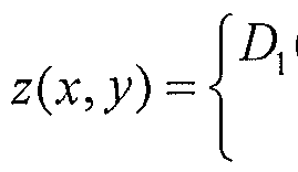
- the set Do can be formed in SL depth map combining module 502 using a threshold-based decision rule:
- Relsi(x,y) can be a binary reliability estimate equal to 0 if the corresponding depth information is missing and 1 if it is present, and in such an arrangement ThresholdsL can be equal to an intermediate value such as 0.5. Numerous alternative reliability estimates, threshold values and threshold-based decision rules may be used.
- an SL depth map comprising a sparse matrix D ⁇ is constructed in combining module 502, with the sparse matrix D ⁇ containing z values in corresponding (x,y) positions and zeros in all other positions.
- ToF depth map combining module 506 a similar approach may be used. Accordingly, the ToF depth estimates and corresponding ToF reliability estimates from the single cell data acquisition modules 120-1 through ⁇ 2Q-K may be processed in the following manner.
- To denote ToF depth imaging information comprising a set of (x,y,z) triples where (x,y) denotes the position of a ToF sensor cell and z is the depth value at position (x,y) obtained using ToF phase information.
- the set To can be formed in ToF depth map combining module 506 using a threshold-based decision rule:
- a variety of different types of reliability estimates Rel T0f (x,y) and thresholds Thresholds can be used.
- a ToF depth map comprising a matrix T ⁇ is constructed in combining module 506, with the matrix T ⁇ containing z values in corresponding (x,y) positions and zeros in all other positions.
- T ⁇ is subject to interpolation-based reconstruction in preprocessor 508 before the ToF and SL depth maps are merged in the depth map merging module 510. This preprocessing more particularly involves reconstructing depth values for those positions that contain zeros in T ⁇ .
- the interpolation in the present embodiment involves identifying a particular pixel having a zero in its position in T ⁇ , identifying a neighborhood of pixels for the particular pixel, and interpolating a depth value for the particular pixel based on depth values of the respective pixels in the neighborhood of pixels. This process is repeated for each of the zero depth value pixels in T ⁇ .
- FIG. 6 shows a pixel neighborhood around a zero depth value pixel in the ToF depth map matrix T ⁇ .
- the pixel neighborhood comprises eight pixels p ⁇ through p % surrounding a particular pixel p.
- Euclidean distance is used in this example, other types of distance metrics may be used, such as a Manhattan distance metric, or more generally a p-norm distance metric.
- An example of d corresponding to a radius of a circle is illustrated in FIG. 6 for the eight-pixel neighborhood of pixel p. It should be understood, however, that numerous other techniques may be used to identify pixel neighborhoods for respective particular pixels.
- the depth value z p for that pixel can be computed as the mean of the depth values of the respective neighboring pixels:
- mean and median used above are just examples of two possible interpolation techniques that may be applied in embodiments of the invention, and numerous other interpolation techniques Icnown to those skilled in the art may be used in place of mean or median interpolation.
- the SL depth map D ⁇ from the SL depth map combining module 502 can also be subject to one or more preprocessing operation, in SL depth map preprocessor 504.
- SL depth map preprocessor 504. interpolation techniques of the type described above for ToF depth map T ⁇ may also be applied to SL depth map in some embodiments.
- SL depth map preprocessing As another example of SL depth map preprocessing, assume that SL depth map has a resolution of MDXND pixels corresponding to the desired size of the merged depth map and ToF depth map T ⁇ from the ToF depth map combining module 506 has a resolution of MT O FXNT O F pixels, where MT 0 F ⁇ 1 ⁇ 2» and NT O F ⁇ No.
- the ToF depth map resolution may be increased to substantially match that of the SL depth map using any of a number of well-known image upsampling techniques, including upsampling techniques based on bilinear or cubic interpolation. Cropping of one or both of the SL and ToF depth maps may be applied before or after depth map resizing if necessary in order to maintain a desired aspect ratio.
- Such upsampling and cropping operations are examples of what are more generally referred to herein as depth image preprocessing operations.
- the depth map merging module 510 in the present embodiment receives a preprocessed SL depth map and a preprocessed ToF depth map, both of substantially equal size or resolution.
- the ToF depth map after upsampling as previously described has the desired merged depth map resolution of MDXND and no pixels with missing depth values, while the SL depth map has the same resolution but may have some pixels with missing depth values.
- These two SL and ToF depth maps may then be merged in module 510 using the following exemplary process:
- calibration may be used in some embodiments.
- the two sensors may be fixed in location relative to one another and then calibrated in the following manner.
- SL and ToF depth images are obtained using the respective sensors. Multiple corresponding points are located in the images, usually at least four such points.
- m the number of such points
- D xyz as a 3 Xm matrix containing the x, y and z coordinates for each of the m points from the SL depth image
- T xyz as a 3 xm matrix containing the x, y and z coordinates for each of the corresponding m points from the ToF depth image.
- a and TR as an affme transform matrix and a translation vector, respectively, determined as optimal in a least mean squares sense, where:
- the next calibration step is to transform the SL depth map D ⁇ into the coordinate system of the ToF depth map T ⁇ .
- This can be done using the already known A and TR affine transform parameters as follows:
- D lxyz A ⁇ D xyz + TR.
- the resulting (x,y) coordinates of pixels in D ⁇ - are not always integers, but are more generally rational numbers. Accordingly, those rational number coordinates can be mapped to a regular grid comprising equidistant orthogonal integer lattice points of the ToF image T ⁇ having resolution MDXND, possibly using interpolation based on nearest neighbors or other techniques. After such a mapping, some points in the regular grid may remain unfilled, but this resulting lacunal lattice is not crucial for application of a super resolution technique. Such a super resolution technique may be applied to obtain an SL depth map D 2 having resolution MDXND and possibly with one or more zero depth pixel positions.
Landscapes
- Engineering & Computer Science (AREA)
- Multimedia (AREA)
- Signal Processing (AREA)
- Physics & Mathematics (AREA)
- General Physics & Mathematics (AREA)
- Theoretical Computer Science (AREA)
- Length Measuring Devices By Optical Means (AREA)
- Measurement Of Optical Distance (AREA)
- Optical Radar Systems And Details Thereof (AREA)
- Image Processing (AREA)
- Image Analysis (AREA)
Abstract
Description


Claims
Priority Applications (5)
| Application Number | Priority Date | Filing Date | Title |
|---|---|---|---|
| JP2015547927A JP2016510396A (en) | 2012-12-17 | 2013-08-23 | Method and apparatus for merging depth images generated using different depth imaging techniques |
| CN201380003684.4A CN104903677A (en) | 2012-12-17 | 2013-08-23 | Methods and apparatus for merging depth images generated using distinct depth imaging techniques |
| CA2846653A CA2846653A1 (en) | 2012-12-17 | 2013-08-23 | Methods and apparatus for merging depth images generated using distinct depth imaging techniques |
| US14/233,943 US20160005179A1 (en) | 2012-12-17 | 2013-08-23 | Methods and apparatus for merging depth images generated using distinct depth imaging techniques |
| KR1020157016193A KR20150096416A (en) | 2012-12-17 | 2013-08-23 | Methods and apparatus for merging depth images generated using distinct depth imaging techniques |
Applications Claiming Priority (2)
| Application Number | Priority Date | Filing Date | Title |
|---|---|---|---|
| RU2012154657 | 2012-12-17 | ||
| RU2012154657/08A RU2012154657A (en) | 2012-12-17 | 2012-12-17 | METHODS AND DEVICE FOR COMBINING IMAGES WITH DEPTH GENERATED USING DIFFERENT METHODS FOR FORMING IMAGES WITH DEPTH |
Publications (2)
| Publication Number | Publication Date |
|---|---|
| WO2014099048A2 true WO2014099048A2 (en) | 2014-06-26 |
| WO2014099048A3 WO2014099048A3 (en) | 2015-07-16 |
Family
ID=50979358
Family Applications (1)
| Application Number | Title | Priority Date | Filing Date |
|---|---|---|---|
| PCT/US2013/056397 Ceased WO2014099048A2 (en) | 2012-12-17 | 2013-08-23 | Methods and apparatus for merging depth images generated using distinct depth imaging techniques |
Country Status (8)
| Country | Link |
|---|---|
| US (1) | US20160005179A1 (en) |
| JP (1) | JP2016510396A (en) |
| KR (1) | KR20150096416A (en) |
| CN (1) | CN104903677A (en) |
| CA (1) | CA2846653A1 (en) |
| RU (1) | RU2012154657A (en) |
| TW (1) | TW201432619A (en) |
| WO (1) | WO2014099048A2 (en) |
Cited By (5)
| Publication number | Priority date | Publication date | Assignee | Title |
|---|---|---|---|---|
| WO2015119657A1 (en) * | 2014-02-07 | 2015-08-13 | Lsi Corporation | Depth image generation utilizing depth information reconstructed from an amplitude image |
| CN107113415A (en) * | 2015-01-20 | 2017-08-29 | 高通股份有限公司 | The method and apparatus for obtaining and merging for many technology depth maps |
| CN108027441A (en) * | 2015-09-08 | 2018-05-11 | 微视公司 | Mixed mode depth detection |
| US11454723B2 (en) | 2016-10-21 | 2022-09-27 | Sony Semiconductor Solutions Corporation | Distance measuring device and distance measuring device control method |
| US12393179B2 (en) | 2019-11-15 | 2025-08-19 | Amgen Inc. | Offline troubleshooting and development for automated visual inspection stations |
Families Citing this family (77)
| Publication number | Priority date | Publication date | Assignee | Title |
|---|---|---|---|---|
| US10848731B2 (en) | 2012-02-24 | 2020-11-24 | Matterport, Inc. | Capturing and aligning panoramic image and depth data |
| US9324190B2 (en) | 2012-02-24 | 2016-04-26 | Matterport, Inc. | Capturing and aligning three-dimensional scenes |
| US11282287B2 (en) | 2012-02-24 | 2022-03-22 | Matterport, Inc. | Employing three-dimensional (3D) data predicted from two-dimensional (2D) images using neural networks for 3D modeling applications and other applications |
| EP4016981A3 (en) | 2013-12-24 | 2022-09-21 | Sony Depthsensing Solutions | A time-of-flight camera system |
| TWI558525B (en) * | 2014-12-26 | 2016-11-21 | 國立交通大學 | Robot and its control method |
| KR20170104506A (en) * | 2015-01-06 | 2017-09-15 | 페이스북, 인크. | Method and system for providing depth mapping using patterned light |
| US10145942B2 (en) | 2015-03-27 | 2018-12-04 | Intel Corporation | Techniques for spatio-temporal compressed time of flight imaging |
| TWI575248B (en) * | 2015-09-10 | 2017-03-21 | 義明科技股份有限公司 | Non-contact optical sensing device and method for sensing depth and position of an object in three-dimensional space |
| CN106527761A (en) | 2015-09-10 | 2017-03-22 | 义明科技股份有限公司 | Non-contact optical sensing device and three-dimensional object depth position sensing method |
| US9983709B2 (en) | 2015-11-02 | 2018-05-29 | Oculus Vr, Llc | Eye tracking using structured light |
| US10025060B2 (en) | 2015-12-08 | 2018-07-17 | Oculus Vr, Llc | Focus adjusting virtual reality headset |
| US10445860B2 (en) | 2015-12-08 | 2019-10-15 | Facebook Technologies, Llc | Autofocus virtual reality headset |
| US10241569B2 (en) | 2015-12-08 | 2019-03-26 | Facebook Technologies, Llc | Focus adjustment method for a virtual reality headset |
| KR102659065B1 (en) * | 2015-12-21 | 2024-04-22 | 코닌클리케 필립스 엔.브이. | Processing of depth maps for images |
| US9858672B2 (en) * | 2016-01-15 | 2018-01-02 | Oculus Vr, Llc | Depth mapping using structured light and time of flight |
| EP3413267B1 (en) * | 2016-02-05 | 2023-06-28 | Ricoh Company, Ltd. | Object detection device, device control system, objection detection method, and program |
| US11106276B2 (en) | 2016-03-11 | 2021-08-31 | Facebook Technologies, Llc | Focus adjusting headset |
| US10379356B2 (en) | 2016-04-07 | 2019-08-13 | Facebook Technologies, Llc | Accommodation based optical correction |
| US10429647B2 (en) | 2016-06-10 | 2019-10-01 | Facebook Technologies, Llc | Focus adjusting virtual reality headset |
| CN105974427B (en) * | 2016-06-24 | 2021-05-04 | 上海图漾信息科技有限公司 | Structured light ranging device and method |
| CN107783353B (en) * | 2016-08-26 | 2020-07-10 | 光宝电子(广州)有限公司 | Device and system for capturing three-dimensional image |
| CN108027238B (en) * | 2016-09-01 | 2022-06-14 | 索尼半导体解决方案公司 | Image forming apparatus with a plurality of image forming units |
| US10712561B2 (en) | 2016-11-04 | 2020-07-14 | Microsoft Technology Licensing, Llc | Interference mitigation via adaptive depth imaging |
| WO2018090250A1 (en) | 2016-11-16 | 2018-05-24 | 深圳市大疆创新科技有限公司 | Three-dimensional point cloud generation method, device, computer system, and mobile apparatus |
| US10025384B1 (en) | 2017-01-06 | 2018-07-17 | Oculus Vr, Llc | Eye tracking architecture for common structured light and time-of-flight framework |
| US10154254B2 (en) | 2017-01-17 | 2018-12-11 | Facebook Technologies, Llc | Time-of-flight depth sensing for eye tracking |
| US10310598B2 (en) | 2017-01-17 | 2019-06-04 | Facebook Technologies, Llc | Varifocal head-mounted display including modular air spaced optical assembly |
| WO2018140656A1 (en) * | 2017-01-26 | 2018-08-02 | Matterport, Inc. | Capturing and aligning panoramic image and depth data |
| US10679366B1 (en) | 2017-01-30 | 2020-06-09 | Facebook Technologies, Llc | High speed computational tracking sensor |
| US10810753B2 (en) * | 2017-02-27 | 2020-10-20 | Microsoft Technology Licensing, Llc | Single-frequency time-of-flight depth computation using stereoscopic disambiguation |
| IL251636B (en) | 2017-04-06 | 2018-02-28 | Yoav Berlatzky | A system and method for a coherent camera |
| US10928489B2 (en) * | 2017-04-06 | 2021-02-23 | Microsoft Technology Licensing, Llc | Time of flight camera |
| CN107345790A (en) * | 2017-07-11 | 2017-11-14 | 合肥康之恒机械科技有限公司 | A kind of electronic product detector |
| CN109729721B (en) | 2017-08-29 | 2021-04-16 | 深圳市汇顶科技股份有限公司 | Optical ranging method and optical ranging device |
| CN107526948B (en) * | 2017-09-28 | 2023-08-25 | 同方威视技术股份有限公司 | Method and device for generating associated image and image verification method and device |
| US11256667B2 (en) | 2017-10-26 | 2022-02-22 | Druva Inc. | Deduplicated merged indexed object storage file system |
| US10215856B1 (en) | 2017-11-27 | 2019-02-26 | Microsoft Technology Licensing, Llc | Time of flight camera |
| CN109870116B (en) * | 2017-12-05 | 2021-08-03 | 光宝电子(广州)有限公司 | Depth imaging apparatus and driving method thereof |
| US10901087B2 (en) | 2018-01-15 | 2021-01-26 | Microsoft Technology Licensing, Llc | Time of flight camera |
| CN108564614B (en) * | 2018-04-03 | 2020-09-18 | Oppo广东移动通信有限公司 | Depth acquisition method and apparatus, computer readable storage medium and computer device |
| CN110349196B (en) * | 2018-04-03 | 2024-03-29 | 联发科技股份有限公司 | Depth fusion method and device |
| US11187804B2 (en) | 2018-05-30 | 2021-11-30 | Qualcomm Incorporated | Time of flight range finder for a structured light system |
| CN108924408B (en) * | 2018-06-15 | 2020-11-03 | 深圳奥比中光科技有限公司 | Depth imaging method and system |
| KR102543027B1 (en) * | 2018-08-31 | 2023-06-14 | 삼성전자주식회사 | Method and apparatus for obtaining 3 dimentional image |
| WO2020045770A1 (en) | 2018-08-31 | 2020-03-05 | Samsung Electronics Co., Ltd. | Method and device for obtaining 3d images |
| CN110895822B (en) * | 2018-09-13 | 2023-09-01 | 虹软科技股份有限公司 | Method of operating a depth data processing system |
| US11393115B2 (en) * | 2018-11-27 | 2022-07-19 | Infineon Technologies Ag | Filtering continuous-wave time-of-flight measurements, based on coded modulation images |
| DE112019006048T5 (en) * | 2018-12-04 | 2021-09-30 | Iee International Electronics & Engineering S.A. | Method for corrected depth measurement with a TOF camera using amplitude-modulated continuous light |
| EP3663799B1 (en) * | 2018-12-07 | 2024-02-07 | Infineon Technologies AG | Apparatuses and methods for determining depth motion relative to a time-of-flight camera in a scene sensed by the time-of-flight camera |
| US20220155454A1 (en) * | 2019-03-22 | 2022-05-19 | Sony Semiconductor Solutions Corporation | Analysis portion, time-of-flight imaging device and method |
| CN109889809A (en) * | 2019-04-12 | 2019-06-14 | 深圳市光微科技有限公司 | Depth camera mould group, depth camera, depth picture capturing method and depth camera mould group forming method |
| KR102812099B1 (en) * | 2019-05-16 | 2025-05-23 | 엘지이노텍 주식회사 | Camera module |
| CN110488240A (en) * | 2019-07-12 | 2019-11-22 | 深圳奥比中光科技有限公司 | Depth calculation chip architecture |
| CN110376602A (en) * | 2019-07-12 | 2019-10-25 | 深圳奥比中光科技有限公司 | Multi-mode depth calculation processor and 3D rendering equipment |
| CN110490920A (en) * | 2019-07-12 | 2019-11-22 | 深圳奥比中光科技有限公司 | Merge depth calculation processor and 3D rendering equipment |
| CN110471080A (en) * | 2019-07-12 | 2019-11-19 | 深圳奥比中光科技有限公司 | Depth measurement device based on TOF imaging sensor |
| CN110333501A (en) * | 2019-07-12 | 2019-10-15 | 深圳奥比中光科技有限公司 | Depth measuring device and distance measuring method |
| CN110456379A (en) * | 2019-07-12 | 2019-11-15 | 深圳奥比中光科技有限公司 | Fusion depth measurement device and distance measurement method |
| CN110673114B (en) * | 2019-08-27 | 2023-04-18 | 三赢科技(深圳)有限公司 | Method and device for calibrating depth of three-dimensional camera, computer device and storage medium |
| KR102900549B1 (en) * | 2019-11-08 | 2025-12-16 | 삼성전자주식회사 | Depth image generation method and depth image generation apparatus |
| CN110930301B (en) * | 2019-12-09 | 2023-08-11 | Oppo广东移动通信有限公司 | Image processing method, device, storage medium and electronic equipment |
| CN114667457B (en) * | 2019-12-11 | 2026-02-13 | 三星电子株式会社 | Electronic devices and their control methods |
| US11373322B2 (en) * | 2019-12-26 | 2022-06-28 | Stmicroelectronics, Inc. | Depth sensing with a ranging sensor and an image sensor |
| WO2021176873A1 (en) * | 2020-03-03 | 2021-09-10 | ソニーグループ株式会社 | Information processing device, information processing method, and program |
| CN114170640B (en) * | 2020-08-19 | 2024-02-02 | 腾讯科技(深圳)有限公司 | Face image processing method, device, computer readable medium and equipment |
| CN112379389B (en) * | 2020-11-11 | 2024-04-26 | 杭州蓝芯科技有限公司 | A depth information acquisition device and method combining structured light camera and TOF depth camera |
| CN113031001B (en) * | 2021-02-24 | 2024-02-13 | Oppo广东移动通信有限公司 | Depth information processing method, depth information processing device, medium and electronic apparatus |
| WO2022194352A1 (en) | 2021-03-16 | 2022-09-22 | Huawei Technologies Co., Ltd. | Apparatus and method for image correlation correction |
| CN113269062B (en) * | 2021-05-14 | 2021-11-26 | 食安快线信息技术(深圳)有限公司 | Artificial intelligence anomaly identification method applied to intelligent education |
| US12544929B2 (en) | 2021-07-21 | 2026-02-10 | Mujin, Inc. | Robotic system with depth-based processing mechanism and methods for operating the same |
| CN115570556B (en) * | 2021-07-21 | 2025-06-17 | 牧今科技 | Robotic system with depth-based processing mechanism and operation method thereof |
| CN114519713B (en) * | 2022-02-24 | 2025-07-18 | 合肥芯明智能科技有限公司 | Depth measurement method, binocular stereoscopic vision system, binocular stereoscopic vision device and storage medium |
| CN115205365A (en) * | 2022-07-14 | 2022-10-18 | 小米汽车科技有限公司 | Vehicle distance detection method and device, vehicle, readable storage medium and chip |
| CN117666136A (en) * | 2022-09-07 | 2024-03-08 | 北京字跳网络技术有限公司 | Head-mounted virtual reality device |
| CN115965942B (en) * | 2023-03-03 | 2023-06-23 | 安徽蔚来智驾科技有限公司 | Position estimation method, vehicle control method, device, medium and vehicle |
| US20240377538A1 (en) * | 2023-05-08 | 2024-11-14 | Microsoft Technology Licensing, Llc | Hybrid depth imaging with sparse subject irradiation |
| CN118330673B (en) * | 2024-06-17 | 2024-10-15 | 欧菲微电子(南昌)有限公司 | Depth imaging module, depth imaging method and electronic device |
Family Cites Families (18)
| Publication number | Priority date | Publication date | Assignee | Title |
|---|---|---|---|---|
| US6515740B2 (en) * | 2000-11-09 | 2003-02-04 | Canesta, Inc. | Methods for CMOS-compatible three-dimensional image sensing using quantum efficiency modulation |
| US8134637B2 (en) * | 2004-01-28 | 2012-03-13 | Microsoft Corporation | Method and system to increase X-Y resolution in a depth (Z) camera using red, blue, green (RGB) sensing |
| US8139141B2 (en) * | 2004-01-28 | 2012-03-20 | Microsoft Corporation | Single chip red, green, blue, distance (RGB-Z) sensor |
| US7560679B1 (en) * | 2005-05-10 | 2009-07-14 | Siimpel, Inc. | 3D camera |
| US7852461B2 (en) * | 2007-11-15 | 2010-12-14 | Microsoft International Holdings B.V. | Dual mode depth imaging |
| US8223215B2 (en) * | 2008-01-30 | 2012-07-17 | Mesa Imaging Ag | Adaptive neighborhood filtering (ANF) system and method for 3D time of flight cameras |
| US8681216B2 (en) * | 2009-03-12 | 2014-03-25 | Hewlett-Packard Development Company, L.P. | Depth-sensing camera system |
| US8717417B2 (en) * | 2009-04-16 | 2014-05-06 | Primesense Ltd. | Three-dimensional mapping and imaging |
| US8681124B2 (en) * | 2009-09-22 | 2014-03-25 | Microsoft Corporation | Method and system for recognition of user gesture interaction with passive surface video displays |
| KR101648201B1 (en) * | 2009-11-04 | 2016-08-12 | 삼성전자주식회사 | Image sensor and for manufacturing the same |
| US8723923B2 (en) * | 2010-01-14 | 2014-05-13 | Alces Technology | Structured light system |
| US8885890B2 (en) * | 2010-05-07 | 2014-11-11 | Microsoft Corporation | Depth map confidence filtering |
| CN201707438U (en) * | 2010-05-28 | 2011-01-12 | 中国科学院合肥物质科学研究院 | Three-dimensional imaging system based on LED array co-lens TOF (Time of Flight) depth measurement |
| EP2395369A1 (en) * | 2010-06-09 | 2011-12-14 | Thomson Licensing | Time-of-flight imager. |
| US9194953B2 (en) * | 2010-10-21 | 2015-11-24 | Sony Corporation | 3D time-of-light camera and method |
| US9030528B2 (en) * | 2011-04-04 | 2015-05-12 | Apple Inc. | Multi-zone imaging sensor and lens array |
| CN102663712B (en) * | 2012-04-16 | 2014-09-17 | 天津大学 | Depth calculation imaging method based on time of flight (TOF) camera |
| US9175957B2 (en) * | 2012-09-24 | 2015-11-03 | Alces Technology, Inc. | Grayscale patterns from binary spatial light modulators |
-
2012
- 2012-12-17 RU RU2012154657/08A patent/RU2012154657A/en not_active Application Discontinuation
-
2013
- 2013-08-23 JP JP2015547927A patent/JP2016510396A/en active Pending
- 2013-08-23 KR KR1020157016193A patent/KR20150096416A/en not_active Withdrawn
- 2013-08-23 WO PCT/US2013/056397 patent/WO2014099048A2/en not_active Ceased
- 2013-08-23 US US14/233,943 patent/US20160005179A1/en not_active Abandoned
- 2013-08-23 CN CN201380003684.4A patent/CN104903677A/en active Pending
- 2013-08-23 CA CA2846653A patent/CA2846653A1/en not_active Abandoned
- 2013-09-18 TW TW102133979A patent/TW201432619A/en unknown
Cited By (7)
| Publication number | Priority date | Publication date | Assignee | Title |
|---|---|---|---|---|
| WO2015119657A1 (en) * | 2014-02-07 | 2015-08-13 | Lsi Corporation | Depth image generation utilizing depth information reconstructed from an amplitude image |
| CN107113415A (en) * | 2015-01-20 | 2017-08-29 | 高通股份有限公司 | The method and apparatus for obtaining and merging for many technology depth maps |
| CN107113415B (en) * | 2015-01-20 | 2019-06-14 | 高通股份有限公司 | Method and apparatus for multi-technology depth map acquisition and fusion |
| US10404969B2 (en) | 2015-01-20 | 2019-09-03 | Qualcomm Incorporated | Method and apparatus for multiple technology depth map acquisition and fusion |
| CN108027441A (en) * | 2015-09-08 | 2018-05-11 | 微视公司 | Mixed mode depth detection |
| US11454723B2 (en) | 2016-10-21 | 2022-09-27 | Sony Semiconductor Solutions Corporation | Distance measuring device and distance measuring device control method |
| US12393179B2 (en) | 2019-11-15 | 2025-08-19 | Amgen Inc. | Offline troubleshooting and development for automated visual inspection stations |
Also Published As
| Publication number | Publication date |
|---|---|
| WO2014099048A3 (en) | 2015-07-16 |
| US20160005179A1 (en) | 2016-01-07 |
| KR20150096416A (en) | 2015-08-24 |
| CN104903677A (en) | 2015-09-09 |
| TW201432619A (en) | 2014-08-16 |
| CA2846653A1 (en) | 2014-06-17 |
| JP2016510396A (en) | 2016-04-07 |
| RU2012154657A (en) | 2014-06-27 |
Similar Documents
| Publication | Publication Date | Title |
|---|---|---|
| US20160005179A1 (en) | Methods and apparatus for merging depth images generated using distinct depth imaging techniques | |
| KR102714153B1 (en) | Method and system for generating a three-dimensional image of an object | |
| US9025862B2 (en) | Range image pixel matching method | |
| CN103824318B (en) | A kind of depth perception method of multi-cam array | |
| CN111566437B (en) | Three-dimensional measurement system and three-dimensional measurement method | |
| Zhu et al. | Fusion of time-of-flight depth and stereo for high accuracy depth maps | |
| KR20150079638A (en) | Image processing method and apparatus for elimination of depth artifacts | |
| US20140139632A1 (en) | Depth imaging method and apparatus with adaptive illumination of an object of interest | |
| US20150187082A1 (en) | System and method for adaptive depth map reconstruction | |
| WO2016066893A1 (en) | Method for alignment of low-quality noisy depth map to the high-resolution colour image | |
| WO2007142643A1 (en) | Two pass approach to three dimensional reconstruction | |
| Hadjitheophanous et al. | Towards hardware stereoscopic 3D reconstruction a real-time FPGA computation of the disparity map | |
| Gao et al. | A refractive camera for acquiring stereo and super-resolution images | |
| KR20170047780A (en) | Low-cost calculation apparatus using the adaptive window mask and method therefor | |
| Ralasic et al. | Dual imaging–can virtual be better than real? | |
| Ambrosch et al. | A miniature embedded stereo vision system for automotive applications | |
| TW201426634A (en) | Target image generation utilizing a functional based on functions of information from other images | |
| KR20230077143A (en) | An enhancement technique of graphics data generated by cameras | |
| JP2018156192A (en) | Image processing apparatus, image processing system, image processing method, and program | |
| Agarwal et al. | Three dimensional image reconstruction using interpolation of distance and image registration | |
| KR101765257B1 (en) | Method for acquiring three dimensional image information, and computing device implementing the samemethod | |
| US20250245843A1 (en) | Image processor and image processing system including the same | |
| Chantara et al. | Efficient depth estimation for light field images | |
| Ajitha et al. | Application of Simulated LIDAR Methodology in Autonomous Aerial Platforms | |
| Huang et al. | Binocular vision 3D reconstruction based on semiglobal block matching and weighted least squares filtering |
Legal Events
| Date | Code | Title | Description |
|---|---|---|---|
| WWE | Wipo information: entry into national phase |
Ref document number: 14233943 Country of ref document: US |
|
| ENP | Entry into the national phase |
Ref document number: 2846653 Country of ref document: CA Kind code of ref document: A |
|
| 121 | Ep: the epo has been informed by wipo that ep was designated in this application |
Ref document number: 13863861 Country of ref document: EP Kind code of ref document: A2 |
|
| ENP | Entry into the national phase |
Ref document number: 2015547927 Country of ref document: JP Kind code of ref document: A |
|
| ENP | Entry into the national phase |
Ref document number: 20157016193 Country of ref document: KR Kind code of ref document: A |
|
| 122 | Ep: pct application non-entry in european phase |
Ref document number: 13863861 Country of ref document: EP Kind code of ref document: A2 |