WO2014098067A1 - 締結部品 - Google Patents
締結部品 Download PDFInfo
- Publication number
- WO2014098067A1 WO2014098067A1 PCT/JP2013/083722 JP2013083722W WO2014098067A1 WO 2014098067 A1 WO2014098067 A1 WO 2014098067A1 JP 2013083722 W JP2013083722 W JP 2013083722W WO 2014098067 A1 WO2014098067 A1 WO 2014098067A1
- Authority
- WO
- WIPO (PCT)
- Prior art keywords
- fastening
- resin
- fastening part
- section
- closed cross
- Prior art date
- Legal status (The legal status is an assumption and is not a legal conclusion. Google has not performed a legal analysis and makes no representation as to the accuracy of the status listed.)
- Ceased
Links
Images


Classifications
-
- B—PERFORMING OPERATIONS; TRANSPORTING
- B29—WORKING OF PLASTICS; WORKING OF SUBSTANCES IN A PLASTIC STATE IN GENERAL
- B29C—SHAPING OR JOINING OF PLASTICS; SHAPING OF MATERIAL IN A PLASTIC STATE, NOT OTHERWISE PROVIDED FOR; AFTER-TREATMENT OF THE SHAPED PRODUCTS, e.g. REPAIRING
- B29C65/00—Joining or sealing of preformed parts, e.g. welding of plastics materials; Apparatus therefor
- B29C65/56—Joining or sealing of preformed parts, e.g. welding of plastics materials; Apparatus therefor using mechanical means or mechanical connections, e.g. form-fits
- B29C65/562—Joining or sealing of preformed parts, e.g. welding of plastics materials; Apparatus therefor using mechanical means or mechanical connections, e.g. form-fits using extra joining elements, i.e. which are not integral with the parts to be joined
-
- B—PERFORMING OPERATIONS; TRANSPORTING
- B29—WORKING OF PLASTICS; WORKING OF SUBSTANCES IN A PLASTIC STATE IN GENERAL
- B29C—SHAPING OR JOINING OF PLASTICS; SHAPING OF MATERIAL IN A PLASTIC STATE, NOT OTHERWISE PROVIDED FOR; AFTER-TREATMENT OF THE SHAPED PRODUCTS, e.g. REPAIRING
- B29C66/00—General aspects of processes or apparatus for joining preformed parts
- B29C66/01—General aspects dealing with the joint area or with the area to be joined
- B29C66/05—Particular design of joint configurations
- B29C66/10—Particular design of joint configurations particular design of the joint cross-sections
- B29C66/11—Joint cross-sections comprising a single joint-segment, i.e. one of the parts to be joined comprising a single joint-segment in the joint cross-section
- B29C66/112—Single lapped joints
-
- B—PERFORMING OPERATIONS; TRANSPORTING
- B29—WORKING OF PLASTICS; WORKING OF SUBSTANCES IN A PLASTIC STATE IN GENERAL
- B29C—SHAPING OR JOINING OF PLASTICS; SHAPING OF MATERIAL IN A PLASTIC STATE, NOT OTHERWISE PROVIDED FOR; AFTER-TREATMENT OF THE SHAPED PRODUCTS, e.g. REPAIRING
- B29C66/00—General aspects of processes or apparatus for joining preformed parts
- B29C66/01—General aspects dealing with the joint area or with the area to be joined
- B29C66/05—Particular design of joint configurations
- B29C66/10—Particular design of joint configurations particular design of the joint cross-sections
- B29C66/11—Joint cross-sections comprising a single joint-segment, i.e. one of the parts to be joined comprising a single joint-segment in the joint cross-section
- B29C66/114—Single butt joints
-
- B—PERFORMING OPERATIONS; TRANSPORTING
- B29—WORKING OF PLASTICS; WORKING OF SUBSTANCES IN A PLASTIC STATE IN GENERAL
- B29C—SHAPING OR JOINING OF PLASTICS; SHAPING OF MATERIAL IN A PLASTIC STATE, NOT OTHERWISE PROVIDED FOR; AFTER-TREATMENT OF THE SHAPED PRODUCTS, e.g. REPAIRING
- B29C66/00—General aspects of processes or apparatus for joining preformed parts
- B29C66/01—General aspects dealing with the joint area or with the area to be joined
- B29C66/05—Particular design of joint configurations
- B29C66/10—Particular design of joint configurations particular design of the joint cross-sections
- B29C66/12—Joint cross-sections combining only two joint-segments; Tongue and groove joints; Tenon and mortise joints; Stepped joint cross-sections
- B29C66/124—Tongue and groove joints
- B29C66/1244—Tongue and groove joints characterised by the male part, i.e. the part comprising the tongue
- B29C66/12443—Tongue and groove joints characterised by the male part, i.e. the part comprising the tongue having the tongue substantially in the middle
-
- B—PERFORMING OPERATIONS; TRANSPORTING
- B29—WORKING OF PLASTICS; WORKING OF SUBSTANCES IN A PLASTIC STATE IN GENERAL
- B29C—SHAPING OR JOINING OF PLASTICS; SHAPING OF MATERIAL IN A PLASTIC STATE, NOT OTHERWISE PROVIDED FOR; AFTER-TREATMENT OF THE SHAPED PRODUCTS, e.g. REPAIRING
- B29C66/00—General aspects of processes or apparatus for joining preformed parts
- B29C66/01—General aspects dealing with the joint area or with the area to be joined
- B29C66/05—Particular design of joint configurations
- B29C66/20—Particular design of joint configurations particular design of the joint lines, e.g. of the weld lines
- B29C66/24—Particular design of joint configurations particular design of the joint lines, e.g. of the weld lines said joint lines being closed or non-straight
- B29C66/242—Particular design of joint configurations particular design of the joint lines, e.g. of the weld lines said joint lines being closed or non-straight said joint lines being closed, i.e. forming closed contours
- B29C66/2422—Particular design of joint configurations particular design of the joint lines, e.g. of the weld lines said joint lines being closed or non-straight said joint lines being closed, i.e. forming closed contours being circular, oval or elliptical
- B29C66/24221—Particular design of joint configurations particular design of the joint lines, e.g. of the weld lines said joint lines being closed or non-straight said joint lines being closed, i.e. forming closed contours being circular, oval or elliptical being circular
-
- B—PERFORMING OPERATIONS; TRANSPORTING
- B29—WORKING OF PLASTICS; WORKING OF SUBSTANCES IN A PLASTIC STATE IN GENERAL
- B29C—SHAPING OR JOINING OF PLASTICS; SHAPING OF MATERIAL IN A PLASTIC STATE, NOT OTHERWISE PROVIDED FOR; AFTER-TREATMENT OF THE SHAPED PRODUCTS, e.g. REPAIRING
- B29C66/00—General aspects of processes or apparatus for joining preformed parts
- B29C66/01—General aspects dealing with the joint area or with the area to be joined
- B29C66/05—Particular design of joint configurations
- B29C66/20—Particular design of joint configurations particular design of the joint lines, e.g. of the weld lines
- B29C66/24—Particular design of joint configurations particular design of the joint lines, e.g. of the weld lines said joint lines being closed or non-straight
- B29C66/242—Particular design of joint configurations particular design of the joint lines, e.g. of the weld lines said joint lines being closed or non-straight said joint lines being closed, i.e. forming closed contours
- B29C66/2424—Particular design of joint configurations particular design of the joint lines, e.g. of the weld lines said joint lines being closed or non-straight said joint lines being closed, i.e. forming closed contours being a closed polygonal chain
- B29C66/24243—Particular design of joint configurations particular design of the joint lines, e.g. of the weld lines said joint lines being closed or non-straight said joint lines being closed, i.e. forming closed contours being a closed polygonal chain forming a quadrilateral
- B29C66/24244—Particular design of joint configurations particular design of the joint lines, e.g. of the weld lines said joint lines being closed or non-straight said joint lines being closed, i.e. forming closed contours being a closed polygonal chain forming a quadrilateral forming a rectangle
-
- B—PERFORMING OPERATIONS; TRANSPORTING
- B29—WORKING OF PLASTICS; WORKING OF SUBSTANCES IN A PLASTIC STATE IN GENERAL
- B29C—SHAPING OR JOINING OF PLASTICS; SHAPING OF MATERIAL IN A PLASTIC STATE, NOT OTHERWISE PROVIDED FOR; AFTER-TREATMENT OF THE SHAPED PRODUCTS, e.g. REPAIRING
- B29C66/00—General aspects of processes or apparatus for joining preformed parts
- B29C66/50—General aspects of joining tubular articles; General aspects of joining long products, i.e. bars or profiled elements; General aspects of joining single elements to tubular articles, hollow articles or bars; General aspects of joining several hollow-preforms to form hollow or tubular articles
- B29C66/51—Joining tubular articles, profiled elements or bars; Joining single elements to tubular articles, hollow articles or bars; Joining several hollow-preforms to form hollow or tubular articles
- B29C66/53—Joining single elements to tubular articles, hollow articles or bars
- B29C66/534—Joining single elements to open ends of tubular or hollow articles or to the ends of bars
- B29C66/5346—Joining single elements to open ends of tubular or hollow articles or to the ends of bars said single elements being substantially flat
-
- B—PERFORMING OPERATIONS; TRANSPORTING
- B29—WORKING OF PLASTICS; WORKING OF SUBSTANCES IN A PLASTIC STATE IN GENERAL
- B29C—SHAPING OR JOINING OF PLASTICS; SHAPING OF MATERIAL IN A PLASTIC STATE, NOT OTHERWISE PROVIDED FOR; AFTER-TREATMENT OF THE SHAPED PRODUCTS, e.g. REPAIRING
- B29C66/00—General aspects of processes or apparatus for joining preformed parts
- B29C66/50—General aspects of joining tubular articles; General aspects of joining long products, i.e. bars or profiled elements; General aspects of joining single elements to tubular articles, hollow articles or bars; General aspects of joining several hollow-preforms to form hollow or tubular articles
- B29C66/51—Joining tubular articles, profiled elements or bars; Joining single elements to tubular articles, hollow articles or bars; Joining several hollow-preforms to form hollow or tubular articles
- B29C66/54—Joining several hollow-preforms, e.g. half-shells, to form hollow articles, e.g. for making balls, containers; Joining several hollow-preforms, e.g. half-cylinders, to form tubular articles
-
- F—MECHANICAL ENGINEERING; LIGHTING; HEATING; WEAPONS; BLASTING
- F16—ENGINEERING ELEMENTS AND UNITS; GENERAL MEASURES FOR PRODUCING AND MAINTAINING EFFECTIVE FUNCTIONING OF MACHINES OR INSTALLATIONS; THERMAL INSULATION IN GENERAL
- F16B—DEVICES FOR FASTENING OR SECURING CONSTRUCTIONAL ELEMENTS OR MACHINE PARTS TOGETHER, e.g. NAILS, BOLTS, CIRCLIPS, CLAMPS, CLIPS OR WEDGES; JOINTS OR JOINTING
- F16B5/00—Joining sheets or plates, e.g. panels, to one another or to strips or bars parallel to them
- F16B5/02—Joining sheets or plates, e.g. panels, to one another or to strips or bars parallel to them by means of fastening members using screw-thread
-
- B—PERFORMING OPERATIONS; TRANSPORTING
- B29—WORKING OF PLASTICS; WORKING OF SUBSTANCES IN A PLASTIC STATE IN GENERAL
- B29C—SHAPING OR JOINING OF PLASTICS; SHAPING OF MATERIAL IN A PLASTIC STATE, NOT OTHERWISE PROVIDED FOR; AFTER-TREATMENT OF THE SHAPED PRODUCTS, e.g. REPAIRING
- B29C66/00—General aspects of processes or apparatus for joining preformed parts
- B29C66/70—General aspects of processes or apparatus for joining preformed parts characterised by the composition, physical properties or the structure of the material of the parts to be joined; Joining with non-plastics material
- B29C66/71—General aspects of processes or apparatus for joining preformed parts characterised by the composition, physical properties or the structure of the material of the parts to be joined; Joining with non-plastics material characterised by the composition of the plastics material of the parts to be joined
-
- B—PERFORMING OPERATIONS; TRANSPORTING
- B29—WORKING OF PLASTICS; WORKING OF SUBSTANCES IN A PLASTIC STATE IN GENERAL
- B29C—SHAPING OR JOINING OF PLASTICS; SHAPING OF MATERIAL IN A PLASTIC STATE, NOT OTHERWISE PROVIDED FOR; AFTER-TREATMENT OF THE SHAPED PRODUCTS, e.g. REPAIRING
- B29C66/00—General aspects of processes or apparatus for joining preformed parts
- B29C66/70—General aspects of processes or apparatus for joining preformed parts characterised by the composition, physical properties or the structure of the material of the parts to be joined; Joining with non-plastics material
- B29C66/71—General aspects of processes or apparatus for joining preformed parts characterised by the composition, physical properties or the structure of the material of the parts to be joined; Joining with non-plastics material characterised by the composition of the plastics material of the parts to be joined
- B29C66/712—General aspects of processes or apparatus for joining preformed parts characterised by the composition, physical properties or the structure of the material of the parts to be joined; Joining with non-plastics material characterised by the composition of the plastics material of the parts to be joined the composition of one of the parts to be joined being different from the composition of the other part
-
- B—PERFORMING OPERATIONS; TRANSPORTING
- B29—WORKING OF PLASTICS; WORKING OF SUBSTANCES IN A PLASTIC STATE IN GENERAL
- B29C—SHAPING OR JOINING OF PLASTICS; SHAPING OF MATERIAL IN A PLASTIC STATE, NOT OTHERWISE PROVIDED FOR; AFTER-TREATMENT OF THE SHAPED PRODUCTS, e.g. REPAIRING
- B29C66/00—General aspects of processes or apparatus for joining preformed parts
- B29C66/70—General aspects of processes or apparatus for joining preformed parts characterised by the composition, physical properties or the structure of the material of the parts to be joined; Joining with non-plastics material
- B29C66/72—General aspects of processes or apparatus for joining preformed parts characterised by the composition, physical properties or the structure of the material of the parts to be joined; Joining with non-plastics material characterised by the structure of the material of the parts to be joined
- B29C66/721—Fibre-reinforced materials
- B29C66/7212—Fibre-reinforced materials characterised by the composition of the fibres
-
- B—PERFORMING OPERATIONS; TRANSPORTING
- B29—WORKING OF PLASTICS; WORKING OF SUBSTANCES IN A PLASTIC STATE IN GENERAL
- B29C—SHAPING OR JOINING OF PLASTICS; SHAPING OF MATERIAL IN A PLASTIC STATE, NOT OTHERWISE PROVIDED FOR; AFTER-TREATMENT OF THE SHAPED PRODUCTS, e.g. REPAIRING
- B29C66/00—General aspects of processes or apparatus for joining preformed parts
- B29C66/70—General aspects of processes or apparatus for joining preformed parts characterised by the composition, physical properties or the structure of the material of the parts to be joined; Joining with non-plastics material
- B29C66/73—General aspects of processes or apparatus for joining preformed parts characterised by the composition, physical properties or the structure of the material of the parts to be joined; Joining with non-plastics material characterised by the intensive physical properties of the material of the parts to be joined, by the optical properties of the material of the parts to be joined, by the extensive physical properties of the parts to be joined, by the state of the material of the parts to be joined or by the material of the parts to be joined being a thermoplastic or a thermoset
- B29C66/739—General aspects of processes or apparatus for joining preformed parts characterised by the composition, physical properties or the structure of the material of the parts to be joined; Joining with non-plastics material characterised by the intensive physical properties of the material of the parts to be joined, by the optical properties of the material of the parts to be joined, by the extensive physical properties of the parts to be joined, by the state of the material of the parts to be joined or by the material of the parts to be joined being a thermoplastic or a thermoset characterised by the material of the parts to be joined being a thermoplastic or a thermoset
- B29C66/7392—General aspects of processes or apparatus for joining preformed parts characterised by the composition, physical properties or the structure of the material of the parts to be joined; Joining with non-plastics material characterised by the intensive physical properties of the material of the parts to be joined, by the optical properties of the material of the parts to be joined, by the extensive physical properties of the parts to be joined, by the state of the material of the parts to be joined or by the material of the parts to be joined being a thermoplastic or a thermoset characterised by the material of the parts to be joined being a thermoplastic or a thermoset characterised by the material of at least one of the parts being a thermoplastic
- B29C66/73921—General aspects of processes or apparatus for joining preformed parts characterised by the composition, physical properties or the structure of the material of the parts to be joined; Joining with non-plastics material characterised by the intensive physical properties of the material of the parts to be joined, by the optical properties of the material of the parts to be joined, by the extensive physical properties of the parts to be joined, by the state of the material of the parts to be joined or by the material of the parts to be joined being a thermoplastic or a thermoset characterised by the material of the parts to be joined being a thermoplastic or a thermoset characterised by the material of at least one of the parts being a thermoplastic characterised by the materials of both parts being thermoplastics
Definitions
- the present invention relates to a fastening part, and in particular, to a fastening part that is made of a resin member and has a fastening portion to another member.
- Fastening parts composed of resin members and having fastening parts to other members are used in various fields (for example, Patent Document 1), but when stress is concentrated locally on the fastening parts due to a large external load.
- the part may break from the fastening part due to a shear load or the like.
- measures are taken to increase the part thickness around the fastening portion or to reinforce the surrounding portion of the fastening portion with a rib. If only measures are taken, the weight of the part may increase and the part may be difficult to mold.
- FIG. 3 shows an example of a fastening part structure of a fastening part made of a resin member.
- the part 21 is fastened to the other member 23 by a bolt 22 as a fastening member.
- a fastening portion structure when a large external load F is applied to the component 21, for example, a reaction force P from the bolt 22 in the fastening portion is applied to the component 21, and this load F and reaction force P are mainly used as the component 21.
- 3 (A) in FIG. 3A at that time, a large stress is concentrated locally on the wall portion, particularly around the fastening portion 24, and the component 21 is caused by a shear load or the like from that portion. May break.
- an object of the present invention is to provide a fastening part capable of effectively suppressing the breakage of the part from the periphery of the fastening part due to a shear load or the like, focusing on the problems in the fastening part structure of the resin fastening part as described above. There is to do.
- a fastening component according to the present invention is formed of a resin member, and in the fastening component having a fastening portion to another member, the periphery of the fastening portion of the resin member is configured in a closed cross-sectional structure. It consists of what is characterized by.
- the fastening part itself having a fastening part to another member is provided with a structure part in which the periphery of the fastening part of the resin member is configured in a closed cross-sectional structure. Since the periphery of the fastening part of the fastening part itself is configured in a closed cross-section structure, the reaction force against the external load or the external load from the fastening member (for example, bolt) side as described above is particularly reduced. It is received by the upper wall side and the lower wall side of the portion constituting the structure, and the load of the load is distributed compared to the case where it is received by only one wall side as in the conventional structure. As a result, the receiving load itself at the load bearing portion around the fastening portion is reduced, and the breakage due to the shear load or the like at that portion is less likely to occur, and the breakage is effectively suppressed.
- the fastening member for example, bolt
- the fastening component according to the present invention it is possible to adopt a form in which the closed cross-sectional structure around the fastening portion is configured by connecting two resin members. If the required closed cross-sectional structure can be formed with a single resin member, there is no problem, but generally it is often difficult to form the closed cross-sectional structure at one time. By connecting the resin members, a closed cross-sectional structure can be easily configured.
- the closed cross-sectional structure around the fastening portion is configured by connecting the two resin members having the open cross-sectional structure between the open portions.
- a desirable hollow closed cross-sectional structure can be easily formed.
- the open part sides may be joined to each other by bonding, for example, but the open part side tip parts may be connected to each other through fitting.
- an engagement portion that can be fitted to each other for example, can be fitted to each other by a one-touch operation, is formed at each of the opening portion side tip portions that face each other. It is possible to adopt a structure for fitting the two together. More specifically, for example, if an engaging portion composed of a convex portion and a concave portion is formed, and the convex portion is fitted into the concave portion through its elastic deformation, the fitting by one-touch operation is possible. In addition, it is possible to adopt a structure in which the connection structure can be maintained without being easily disengaged after being once fitted.
- the two resin members constituting the closed cross-sectional structure around the fastening part of the fastening part can be made of molded products of different kinds of resins, and the same kind of resin can be used. It can also comprise a molded product.
- the molded parts are made of different types of resin, the most appropriate resin type can be selected according to the load to be borne by the load bearing part around the fastening part of each resin member. From the viewpoints of adhesion, fitting, etc. at the connecting portions of the two resin members, it is possible to select a resin type having optimum performance.
- the molded products are made of the same kind of resin, it is possible to facilitate the manufacture, particularly the molding, and further reduce the manufacturing cost.
- the fastening member for example, a bolt
- the fastening member in the fastening part may have a structure that extends from the upper wall side of the closed cross-section structure to the other member through the lower wall side. it can.
- the fastening part itself has a closed section structure around the fastening part itself, so that an external load or fastening member that is particularly loaded on the part is formed.
- the reaction force against the external load from the side is distributed and received on the upper wall side and the lower wall side in the closed cross-section structure of the fastening part, and the load burden is appropriately distributed, so that the local load around the fastening part Stress can be reduced.
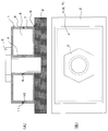
- FIG. 1 shows a fastening part of a fastening part according to an embodiment of the present invention.
- reference numeral 1 denotes a fastening component that is formed of a resin member and has a fastening portion 4 that can be fastened to the other member 2 with a bolt 3 as a fastening member.
- Reference numeral 5 denotes a fastening surface between the fastening component 1 and the other member 2.
- the bolt 3 has a head portion, and in the present embodiment, the connection structure of the two resin members 6 and 7 forms a closed cross-sectional structure 8 around the fastening portion 4 of the fastening component 1.
- the bolt 3 has its head located on the upper wall of FIG. 1A of the closed section structure 8 and penetrates the lower wall of FIG. 1A of the closed section structure 8. It extends into the other member 2.
- the two resin members 6 and 7 are constituted by resin members having an open cross-sectional structure, and the two resin members 6 and 7 are disposed between the open portions, particularly between the open ends.
- the closed cross-section structure 8 is configured by the connection.
- this connection is achieved by a fitting structure 11 between the convex portion 9 formed at the opening portion side tip portion of the resin member 7 and the concave portion 10 formed at the opening portion side tip portion of the resin member 6. Has been achieved.
- the size of the convex portion 9 is a size that can be press-fitted into the concave portion 10, or the entrance side of the concave portion 10 is slightly smaller than the maximum width of the convex portion 9, and the inside of the concave portion 10 is substantially equal to the maximum width of the convex portion 9.
- the convex portion 9 is slightly elastically deformed and fitted into the concave portion 10 so that it cannot be easily removed after fitting. That is, it is configured to be able to complete fitting by a one-touch operation.
- the periphery of the fastening portion 4 of the fastening component 1 itself having the fastening portion 4 to the other member 2 is configured in the closed cross-sectional structure 8, and thus particularly shown in FIG.
- the load constitutes the closed section structure 8 of the fastening portion 4.
- the upper wall side and the lower wall side of FIG. As compared with the case where the fastening part 1 is received only on one side of the wall as in the conventional structure, the load of the load to be received is dispersed. Therefore, the receiving load itself in the load bearing portion around the fastening portion 4 is reduced, and accordingly, breakage due to a shear load or the like around the fastening portion 4 is less likely to occur, and the breakage is effectively suppressed. become.
- a closed cross-sectional structure 8 is achieved by connecting the open portions of the two resin members 6, 7, particularly between the open-end-side tips, and in particular by the fitting structure 11 of the convex portion 9 and the concave portion 10.
- FIG. 2 shows a fastening part of a fastening part according to another embodiment of the present invention.
- the resin member 14 on the fastening surface 5 side of the two resin members 6 and 14 constituting the closed cross-sectional structure 13 around the fastening portion of the fastening part 12 is The cross section shown in FIG. 2A has an H-shaped cross section. That is, the resin member 14 has a web portion 15 having an H-shaped cross section at the center in the vertical direction in FIG. 2A, and is opened to the fastening surface 5 side portion of the resin member 14 toward the fastening surface 5 side. A space 16 is formed.
- the structure of other parts is in accordance with the embodiment shown in FIG.
- the same operation and effect as in the embodiment shown in FIG. 1 can be obtained with respect to configuring the closed section structure 13 and configuring the closed section structure 13 with the two resin members 6 and 14.
- the resin member 14 on the fastening surface 5 side is configured as a member having an H-shaped cross section, and the space 16 is formed on the fastening surface 5 side of the resin member 14, so that FIG. ) If it is difficult in design to ground the surface of the resin member 7 on the fastening surface 5 side to the other member 2 over the entire surface, or grounding to the other member 2 over the entire surface, there is a risk of causing some trouble. In some cases, it is possible to easily remove design difficulties and avoid problems.
- thermoplastic resin materials include polyolefins such as polyethylene (PE), polypropylene (PP), polybutylene, styrene resins, polyethylene terephthalate (PET), polybutylene terephthalate (PBT), polytrimethylene terephthalate (PTT).
- PEN Polyethylene naphthalate
- polyester such as liquid crystal polyester, polyoxymethylene (POM), polyamide (PA), polycarbonate (PC), polymethylene methacrylate (PMMA), polyvinyl chloride (PVC), polyphenylene sulfide (PPS) ), Polyphenylene ether (PPE), modified PPE, polyimide (PI), polyamideimide (PAI), polyetherimide (PEI), polysulfone (PSU), modified PSU, poly -Tersulfone (PES), polyketone (PK), polyetherketone (PEK), polyetheretherketone (PEEK), polyetherketoneketone (PEKK), polyarylate (PAR), polyethernitrile (PEN), phenolic resin, Examples include fluororesins such as phenoxy resin and polytetrafluoroethylene, and thermoplastic elastomers such as polystyrene, polyolefin, polyurethane, polyester, polyamide, polybutadiene, polyisopre
- PC resin and ABS resin and their blend materials are more preferably used from the viewpoint of high elongation
- PA resin, PPS resin and their blend materials are more preferably used from the viewpoint of high strength.
- the two resin members 6 and 7 (14) connected to each other can be formed of molded products of different kinds of resins, or can be formed of molded products of the same kind of resin. In the case of being formed of different types of resin molded products, it is possible to give each resin member an optimum function.
- combinations of resins different from each other for example, the following combinations can be exemplified when shown corresponding to Examples 1 to 10 shown in Table 1.
- Example 1 PA6 and PPS
- Example 2 PP and PA6
- Example 3 30% PC and PA6 + GF
- Example 4 PA6 + GF 30% and PPS + CF 30%
- Example 5 PA6 and PA6 + GF 30%
- Example 6 PA6 + GF 30% and PA6 / elastomer alloy
- Example 7 PBT / PC and PA6 + GF 45%
- Example 8 PBT / PC and POM
- Example 9 PBT + GF 30% and ABS
- Example 10 PPS + GF 40% and PA6 + GF 45%.
- CF represents carbon fiber
- GF represents glass fiber.
- Table 1 exemplifies the above combination example corresponding to the above-described two resin members 6 and 7 in FIG. 1 in Examples 1 to 10, and the function mainly in the fastening surface 5 expected in the combination. .
- the fastening part according to the present invention can be applied to any field where suppression of breakage from a fastening part of a resin fastening part is required.
Landscapes
- Engineering & Computer Science (AREA)
- Mechanical Engineering (AREA)
- General Engineering & Computer Science (AREA)
- Connection Of Plates (AREA)
- Bolts, Nuts, And Washers (AREA)
Abstract
樹脂部材(6、7)で構成され、他部材への締結部(4)を有する締結部品(1)において、締結部品(1)自体における、樹脂部材(6、7)の締結部(4)周囲を閉断面構造(8)に構成した締結部品(1)。締結部品(1)自体の締結部(4)周囲部が閉断面構造(8)に構成されていることにより、とくに締結部品(1)に負荷される外部荷重や締結部材(3)側からの外部荷重に対する反力が、締結部(4)の閉断面構造(8)における上壁側と下壁側とで分散されて受け止められ、荷重の負担を適切に分散させて、局所的な応力を低減することができる。その結果、締結部(4)周囲部での剪断荷重等による破断を効果的に抑制できる。
Description
本発明は、締結部品に関し、とくに、樹脂部材で構成され、他部材への締結部を有する締結部品に関する。
樹脂部材で構成され、他部材への締結部を有する締結部品は、各種分野で用いられているが(例えば、特許文献1)、大きな外部荷重の負荷により締結部に局所的に応力が集中すると、剪断荷重等により部品が締結部から破断することがある。通常は、このような破断を防止、抑制するために、締結部周囲の部品肉厚を大きくしたり、締結部の周囲部をリブで補強したりする対策が施されるが、単にこのような対策を採るだけでは、部品の重量増加や、部品成形の困難性を招くことがある。
また、部品肉厚を実質的に大きくせずに、締結部を重点的に補強したり、締結部に局所的に大きな荷重がかかったりするのを効率よく抑制することは、特別な工夫を加えない限り一般に困難である。
例えば、図3に樹脂部材で構成される締結部品の締結部構造の一例を示すが、部品21が、締結部材としてのボルト22により他部材23に締結されている。このような締結部構造において、部品21に大きな外部荷重Fが負荷されると、締結部における、例えばボルト22からの反力Pが部品21にかかり、この荷重Fや反力Pが主として部品21の図3(A)の上壁で受け止められることになるが、そのとき、その壁部のとくに締結部周囲部24に局所的に大きな応力が集中し、その部分から部品21が剪断荷重等により破断するおそれがある。
そこで本発明の課題は、上述したような樹脂製締結部品の締結部構造における問題点に着目し、部品が締結部周囲から剪断荷重等により破断することを効果的に抑制可能な締結部品を提供することにある。
上記課題を解決するために、本発明に係る締結部品は、樹脂部材で構成され、他部材への締結部を有する締結部品において、前記樹脂部材の前記締結部周囲を閉断面構造に構成したことを特徴とするものからなる。
このような本発明に係る締結部品においては、他部材への締結部を有する締結部品自体に、樹脂部材の締結部周囲を閉断面構造に構成した構造部が設けられる。締結部品自体の締結部周囲部が閉断面構造に構成されていることにより、とくに前述したような外部荷重または締結部材(例えば、ボルト)側からの外部荷重に対する反力が、締結部の閉断面構造を構成している部分の上壁側と下壁側とで受け止められることになり、従来構造のように片側の壁側のみで受け止められる場合に比べ、荷重の負担が分散される。その結果、締結部周囲における荷重負担部における受け止め荷重自身が軽減され、その分、その部位での剪断荷重等による破断が生じにくくなり、破断が効果的に抑制される。
上記本発明に係る締結部品においては、上記締結部周囲の閉断面構造が、2つの樹脂部材の接続により構成されている形態を採用することができる。単一の樹脂部材で必要な閉断面構造を成形できれば、それで問題はないが、一般的に閉断面構造を一時に成形することが困難な場合が多いので、そのような場合には、2つの樹脂部材の接続により、容易に閉断面構造を構成することが可能になる。
また、上記締結部周囲の閉断面構造が、開放断面構造を有する2つの樹脂部材の、開放部側同士の接続により構成されている形態を採用することができる。このような形態においては、容易に、望ましい中空閉断面構造を構成することができる。
この場合、上記開放部側同士を、例えば接着により接合した構造とすることも可能であるが、開放部側先端部同士の嵌合を介して接続されている構造とすることも可能である。例えば、互いに対向する開放部側先端部のそれぞれに、互いに嵌合し合うことが可能な、例えばワンタッチ操作で互いに嵌合し合うことが可能な係合部を形成しておき、係合部同士を互いに嵌合させる構造を採用できる。より具体的には、例えば、凸部と凹部とからなる係合部を形成し、凸部がその弾性変形を介して凹部内に嵌合される構造としておけば、ワンタッチ操作での嵌合が可能になるとともに、一旦嵌合された後には簡単には嵌合が外れず、接続構造を維持できる構造を採用できる。
また、本発明に係る締結部品においては、締結部品の締結部周囲の閉断面構造を構成する上記2つの樹脂部材を、互いに異種の樹脂の成形品から構成することもでき、互いに同種の樹脂の成形品から構成することもできる。互いに異種の樹脂の成形品からなる場合には、各樹脂部材の締結部周囲の荷重負担部での負担すべき荷重に応じて最適な樹脂種を選択でき、また、閉断面構造を構成する際の両樹脂部材の接続部における接着や嵌合等の面から、それぞれ最適な性能を有する樹脂種を選択できる。また、互いに同種の樹脂の成形品からなる場合には、製造、とくに成形の容易化、さらには製造コストの低減をはかることが可能である。
また、本発明に係る締結部品においては、上記締結部における締結部材(例えば、ボルト)が、上記閉断面構造の上壁側から下壁側を貫通して他部材へと延びる構造とすることができる。
このように、本発明に係る締結部品によれば、締結部品自体に、締結部品自体の締結部周囲部が閉断面構造に構成されていることにより、とくに部品に負荷される外部荷重や締結部材側からの外部荷重に対する反力が、締結部の閉断面構造における上壁側と下壁側とで分散されて受け止められることになり、荷重の負担を適切に分散させて、締結部周囲における局所的な応力を低減することができる。その結果、締結部周囲部での剪断荷重等による破断を効果的に抑制することが可能になる。
以下に、本発明の実施の形態を、図面を参照しながら説明する。
図1は、本発明の一実施態様に係る締結部品の締結部を示している。図1において、1は、樹脂部材で構成され、他部材2に締結部材としてのボルト3で締結可能な締結部4を有する締結部品を示している。5は、締結部品1と他部材2との締結面を示している。本実施態様では、ボルト3はその頭部をまた、本実施態様では、2つの樹脂部材6、7の接続構造により、締結部品1の締結部4周囲の閉断面構造8が構成されている。また、本実施態様では、ボルト3は、その頭部を閉断面構造8の図1(A)の上壁上に位置させ、閉断面構造8の図1(A)の下壁を貫通して他部材2中へと延びている。
図1は、本発明の一実施態様に係る締結部品の締結部を示している。図1において、1は、樹脂部材で構成され、他部材2に締結部材としてのボルト3で締結可能な締結部4を有する締結部品を示している。5は、締結部品1と他部材2との締結面を示している。本実施態様では、ボルト3はその頭部をまた、本実施態様では、2つの樹脂部材6、7の接続構造により、締結部品1の締結部4周囲の閉断面構造8が構成されている。また、本実施態様では、ボルト3は、その頭部を閉断面構造8の図1(A)の上壁上に位置させ、閉断面構造8の図1(A)の下壁を貫通して他部材2中へと延びている。
また、本実施態様では、上記2つの樹脂部材6、7は、開放断面構造を有する樹脂部材から構成され、これら2つの樹脂部材6、7の開放部側同士の、とくに開放部側先端部同士の接続により、閉断面構造8が構成されている。この接続は、とくに本実施態様では、樹脂部材7の開放部側先端部に形成された凸部9と、樹脂部材6の開放部側先端部に形成された凹部10との嵌合構造11によって達成されている。凸部9のサイズは、凹部10に対して、圧入可能なサイズに、あるいは凹部10の入口側が凸部9の最大幅よりも若干小さいサイズに凹部10内が凸部9の最大幅と略同等のサイズに形成されており、凸部9が若干弾性変形されて凹部10内に嵌合され、嵌合後には容易には抜けない構造とされている。すなわち、ワンタッチ操作にて嵌合完了可能な構造に構成されている。
上記実施態様に係る締結部品1においては、他部材2への締結部4を有する締結部品1自体の締結部4周囲部が閉断面構造8に構成されていることにより、とくに図3に示したような外部荷重Fやボルト3側からの反力Pが負荷される際、その荷重が、締結部4の閉断面構造8を構成している図1(A)の上壁側と下壁側との両方で受け止められることになり、締結部品1として、従来構造のように片側の壁側のみで受け止められる場合に比べ、受け止めるべき荷重の負担が分散される。したがって、締結部4周囲における荷重負担部における受け止め荷重自身が軽減されることになり、その分、締結部4周囲での剪断荷重等による破断が生じにくくなり、破断が効果的に抑制されることになる。
また、締結部4周囲部の閉断面構造8を2つの樹脂部材6、7の接続により構成することにより、閉断面構造が一体成形では成形しにくい場合にあっても、2つの成形品の合わせ構造として容易に構成することが可能になる。とくに本実施態様のように、2つの樹脂部材6、7の開放部側同士の、とくに開放部側先端部同士の接続により、中でも凸部9と凹部10との嵌合構造11によって閉断面構造8を構成できるようにすることにより、締結前の所望の締結部品1を極めて簡単に完成させることができ、部品製造の容易化、低コスト化を実現することが可能となる。
図2は、本発明の別の実施態様に係る締結部品の締結部を示している。本実施態様においては、図1に示した実施態様に比べ、締結部品12の締結部周囲の閉断面構造13を構成する2つの樹脂部材6、14のうち締結面5側の樹脂部材14が、図2(A)に示す断面にてH形断面形状に形成されている。すなわち、樹脂部材14の図2(A)における上下方向中央部にH形断面形状のウエブ部15を有し、樹脂部材14の締結面5側部位には、締結面5側に向けて開放された空間16が形成されている。その他の部位の構成は図1に示した実施態様に準じる。
本実施態様においても、閉断面構造13を構成すること、2つの樹脂部材6、14で閉断面構造13を構成することについては、図1に示した実施態様と同様の作用、効果が得られる。さらに本実施態様においては、締結面5側の樹脂部材14をH形断面形状の部材に構成し、樹脂部材14の締結面5側に空間16を形成した構造とすることにより、図1(A)に示したように樹脂部材7の締結面5側の面を全面にわたって他部材2に接地させることが設計的に困難な場合や、全面にわたって他部材2に接地させると何らかの不具合を生じるおそれがある場合等に、容易に設計的な困難性を除去し、不具合が生じることを回避できる。
本発明に係る締結部品に用いられる部材構成材料としては、樹脂を含む材料、中でも熱可塑性樹脂を含む材料を挙げることができる。好ましい熱可塑性樹脂材料としては、ポリエチレン(PE)、ポリプロピレン(PP)、ポリブチレン等のポリオレフィンや、スチレン系樹脂の他や、ポリエチレンテレフタレート(PET)、ポリブチレンテレフタレート(PBT)、ポリトリメチレンテレフタレート(PTT)、ポリエチレンナフタレート(PEN)、液晶ポリエステル等のポリエステル、ポリオキシメチレン(POM)、ポリアミド(PA)、ポリカーボネート(PC)、ポリメチレンメタクリレート(PMMA)、ポリ塩化ビニル(PVC)、ポリフェニレンスルフィド(PPS)、ポリフェニレンエーテル(PPE)、変性PPE、ポリイミド(PI)、ポリアミドイミド(PAI)、ポリエーテルイミド(PEI)、ポリスルホン(PSU)、変性PSU、ポリエーテルスルホン(PES)、ポリケトン(PK)、ポリエーテルケトン(PEK)、ポリエーテルエーテルケトン(PEEK)、ポリエーテルケトンケトン(PEKK)、ポリアリレート(PAR)、ポリエーテルニトリル(PEN)、フェノール系樹脂、フェノキシ樹脂、ポリテトラフルオロエチレンなどのフッ素系樹脂、更にポリスチレン系、ポリオレフィン系、ポリウレタン系、ポリエステル系、ポリアミド系、ポリブタジエン系、ポリイソプレン系、フッ素系等の熱可塑エラストマー等が挙げられ、これらの共重合体、変性体、および2種類以上ブレンドした樹脂などであってもよい。とりわけ、高伸度の観点からはPC樹脂やABS樹脂およびそれらのブレンド材が、高強度の観点からはPA樹脂、PPS樹脂およびそれらのブレンド材がより好ましく用いられる。
上記互いに接続される2つの樹脂部材6、7(14)は、前述したように、互いに異種の樹脂の成形品から構成することもでき、互いに同種の樹脂の成形品から構成することもできる。互いに異種の樹脂の成形品からなる場合には、各樹脂部材にそれぞれ最適な機能を持たせることが可能である。互いに異種の樹脂の組み合わせとしては、例えば、表1に示す実施例1~10に対応させて示すと、下記のような組み合わせを例示できる。
実施例1:PA6とPPS、
実施例2:PPとPA6、
実施例3:PCとPA6+GF30%、
実施例4:PA6+GF30%とPPS+CF30%、
実施例5:PA6とPA6+GF30%、
実施例6:PA6+GF30%とPA6/エラストマーアロイ、
実施例7:PBT/PCとPA6+GF45%、
実施例8:PBT/PCとPOM、
実施例9:PBT+GF30%とABS、
実施例10:PPS+GF40%とPA6+GF45%。
上記において、CFは炭素繊維、GFはガラス繊維をそれぞれ示している。
実施例1:PA6とPPS、
実施例2:PPとPA6、
実施例3:PCとPA6+GF30%、
実施例4:PA6+GF30%とPPS+CF30%、
実施例5:PA6とPA6+GF30%、
実施例6:PA6+GF30%とPA6/エラストマーアロイ、
実施例7:PBT/PCとPA6+GF45%、
実施例8:PBT/PCとPOM、
実施例9:PBT+GF30%とABS、
実施例10:PPS+GF40%とPA6+GF45%。
上記において、CFは炭素繊維、GFはガラス繊維をそれぞれ示している。
表1に、実施例1~10における前述の図1の2つの樹脂部材6、7に対応させた場合の上記の組み合わせ例と、その組み合わせにおいて期待される主として締結面5における機能とを例示する。

本発明に係る締結部品は、樹脂製締結部品の締結部からの破断の抑制が求められるあらゆる分野に適用可能である。
1、12 締結部品
2 他部材
3 締結部材としてのボルト
4 締結部
5 締結面
6、7、14 樹脂部材
8、13 閉断面構造
9 凸部
10 凹部
11 嵌合構造
15 ウエブ部
16 空間
2 他部材
3 締結部材としてのボルト
4 締結部
5 締結面
6、7、14 樹脂部材
8、13 閉断面構造
9 凸部
10 凹部
11 嵌合構造
15 ウエブ部
16 空間
Claims (7)
- 樹脂部材で構成され、他部材への締結部を有する締結部品において、前記樹脂部材の前記締結部周囲を閉断面構造に構成したことを特徴とする締結部品。
- 前記締結部周囲の閉断面構造が、2つの樹脂部材の接続により構成されている、請求項1に記載の締結部品。
- 前記締結部周囲の閉断面構造が、開放断面構造を有する2つの樹脂部材の、開放部側同士の接続により構成されている、請求項1または2に記載の締結部品。
- 前記開放部側同士が、開放部側先端部同士の嵌合を介して接続されている、請求項3に記載の締結部品。
- 前記2つの樹脂部材が、互いに異種の樹脂の成形品からなる、請求項2~4のいずれかに記載の締結部品。
- 前記2つの樹脂部材が、同種の樹脂の成形品からなる、請求項2~4のいずれかに記載の締結部品。
- 前記締結部における締結部材が、前記閉断面構造の上壁側から下壁側を貫通して延びる、請求項1~6のいずれかに記載の締結部品。
Priority Applications (1)
| Application Number | Priority Date | Filing Date | Title |
|---|---|---|---|
| JP2014501117A JPWO2014098067A1 (ja) | 2012-12-18 | 2013-12-17 | 締結部品 |
Applications Claiming Priority (2)
| Application Number | Priority Date | Filing Date | Title |
|---|---|---|---|
| JP2012-275709 | 2012-12-18 | ||
| JP2012275709 | 2012-12-18 |
Publications (1)
| Publication Number | Publication Date |
|---|---|
| WO2014098067A1 true WO2014098067A1 (ja) | 2014-06-26 |
Family
ID=50978394
Family Applications (1)
| Application Number | Title | Priority Date | Filing Date |
|---|---|---|---|
| PCT/JP2013/083722 Ceased WO2014098067A1 (ja) | 2012-12-18 | 2013-12-17 | 締結部品 |
Country Status (2)
| Country | Link |
|---|---|
| JP (1) | JPWO2014098067A1 (ja) |
| WO (1) | WO2014098067A1 (ja) |
Citations (2)
| Publication number | Priority date | Publication date | Assignee | Title |
|---|---|---|---|---|
| JPS5885838U (ja) * | 1981-12-07 | 1983-06-10 | 株式会社富士通ゼネラル | 無線通信機の取付装置 |
| JPS5965579U (ja) * | 1982-10-25 | 1984-05-01 | マスプロ電工株式会社 | 小型電子機器ケ−ス |
-
2013
- 2013-12-17 WO PCT/JP2013/083722 patent/WO2014098067A1/ja not_active Ceased
- 2013-12-17 JP JP2014501117A patent/JPWO2014098067A1/ja active Pending
Patent Citations (2)
| Publication number | Priority date | Publication date | Assignee | Title |
|---|---|---|---|---|
| JPS5885838U (ja) * | 1981-12-07 | 1983-06-10 | 株式会社富士通ゼネラル | 無線通信機の取付装置 |
| JPS5965579U (ja) * | 1982-10-25 | 1984-05-01 | マスプロ電工株式会社 | 小型電子機器ケ−ス |
Also Published As
| Publication number | Publication date |
|---|---|
| JPWO2014098067A1 (ja) | 2017-01-12 |
Similar Documents
| Publication | Publication Date | Title |
|---|---|---|
| US20130031756A1 (en) | Self-Locking Fastener | |
| JP5753188B2 (ja) | パイプジョイント | |
| JP5185381B2 (ja) | ファスナ、ファスナ構成要素、及びファスナ・レセプタクル | |
| WO2013053423A3 (en) | Operating fluid container | |
| KR102259793B1 (ko) | 폐수 처리조 내의 조류를 생성하기 위한 교반 부재 및 교반 장치 | |
| US20140044548A1 (en) | Ceiling Fan Blade | |
| TW200934004A (en) | Electrical connector with tethered cover | |
| HK1218097A1 (zh) | 聚氨酯振动筛 | |
| WO2014098067A1 (ja) | 締結部品 | |
| CN204378493U (zh) | 轮子结构 | |
| CN104071444A (zh) | 物品收容容器 | |
| US20180076537A1 (en) | Molded portion-equipped electric wire | |
| US9890794B2 (en) | Fan assembly | |
| US20110086122A1 (en) | Detachable punch mold | |
| CN107002730A (zh) | 防止注塑成型部件分离的紧固装置 | |
| JP2009144765A (ja) | シールパッキン | |
| JP6249300B2 (ja) | 締結部を有する構造体の補強構造 | |
| JP2015014339A (ja) | 長尺体カバーの接続構造 | |
| CN204572666U (zh) | 一种组合式扣件 | |
| JP2014119064A (ja) | エネルギー吸収締結構造 | |
| KR101426670B1 (ko) | 판형 단위 블록 및 판형 단위 블록 세트 | |
| US20160052688A1 (en) | Interior and exterior pipe end cover | |
| CN206641466U (zh) | 一种拉片及具有该拉片的拉链 | |
| CN101885353B (zh) | 一种沙滩车座垫锁 | |
| JP6034357B2 (ja) | ハードフレームタイプスーツケース |
Legal Events
| Date | Code | Title | Description |
|---|---|---|---|
| ENP | Entry into the national phase |
Ref document number: 2014501117 Country of ref document: JP Kind code of ref document: A |
|
| 121 | Ep: the epo has been informed by wipo that ep was designated in this application |
Ref document number: 13863806 Country of ref document: EP Kind code of ref document: A1 |
|
| NENP | Non-entry into the national phase |
Ref country code: DE |
|
| 122 | Ep: pct application non-entry in european phase |
Ref document number: 13863806 Country of ref document: EP Kind code of ref document: A1 |