WO2014080966A1 - Drug inspection device - Google Patents
Drug inspection device Download PDFInfo
- Publication number
- WO2014080966A1 WO2014080966A1 PCT/JP2013/081353 JP2013081353W WO2014080966A1 WO 2014080966 A1 WO2014080966 A1 WO 2014080966A1 JP 2013081353 W JP2013081353 W JP 2013081353W WO 2014080966 A1 WO2014080966 A1 WO 2014080966A1
- Authority
- WO
- WIPO (PCT)
- Prior art keywords
- image
- drug
- area
- medicine
- region
- Prior art date
Links
- 239000003814 drug Substances 0.000 title claims abstract description 333
- 238000007689 inspection Methods 0.000 title claims abstract description 142
- 229940079593 drug Drugs 0.000 title claims abstract description 114
- 238000004806 packaging method and process Methods 0.000 claims abstract description 63
- 229940000406 drug candidate Drugs 0.000 claims abstract description 41
- 238000009795 derivation Methods 0.000 claims abstract description 24
- 238000000605 extraction Methods 0.000 claims abstract description 24
- 238000001514 detection method Methods 0.000 claims abstract description 19
- 238000009826 distribution Methods 0.000 claims abstract description 10
- 238000000034 method Methods 0.000 claims description 110
- 238000005286 illumination Methods 0.000 claims description 94
- 238000003384 imaging method Methods 0.000 claims description 20
- 230000000873 masking effect Effects 0.000 claims description 9
- 238000000354 decomposition reaction Methods 0.000 claims description 5
- 230000001678 irradiating effect Effects 0.000 claims description 3
- 235000019557 luminance Nutrition 0.000 description 33
- 239000000126 substance Substances 0.000 description 13
- 239000003795 chemical substances by application Substances 0.000 description 12
- 239000011324 bead Substances 0.000 description 10
- 230000037303 wrinkles Effects 0.000 description 6
- 238000012856 packing Methods 0.000 description 4
- 238000003825 pressing Methods 0.000 description 4
- 229940126589 solid medicine Drugs 0.000 description 4
- 238000011144 upstream manufacturing Methods 0.000 description 4
- 230000004048 modification Effects 0.000 description 3
- 238000012986 modification Methods 0.000 description 3
- 238000005520 cutting process Methods 0.000 description 2
- 210000003205 muscle Anatomy 0.000 description 2
- 238000009512 pharmaceutical packaging Methods 0.000 description 2
- QNRATNLHPGXHMA-XZHTYLCXSA-N (r)-(6-ethoxyquinolin-4-yl)-[(2s,4s,5r)-5-ethyl-1-azabicyclo[2.2.2]octan-2-yl]methanol;hydrochloride Chemical compound Cl.C([C@H]([C@H](C1)CC)C2)CN1[C@@H]2[C@H](O)C1=CC=NC2=CC=C(OCC)C=C21 QNRATNLHPGXHMA-XZHTYLCXSA-N 0.000 description 1
- 241001270131 Agaricus moelleri Species 0.000 description 1
- 230000001154 acute effect Effects 0.000 description 1
- 239000002775 capsule Substances 0.000 description 1
- 230000007547 defect Effects 0.000 description 1
- 238000010586 diagram Methods 0.000 description 1
- 239000000284 extract Substances 0.000 description 1
- 229910052738 indium Inorganic materials 0.000 description 1
- 239000002184 metal Substances 0.000 description 1
- 238000007781 pre-processing Methods 0.000 description 1
- 238000011946 reduction process Methods 0.000 description 1
- 239000011347 resin Substances 0.000 description 1
- 229920005989 resin Polymers 0.000 description 1
- 230000011218 segmentation Effects 0.000 description 1
- 238000000926 separation method Methods 0.000 description 1
Images


Classifications
-
- G—PHYSICS
- G06—COMPUTING; CALCULATING OR COUNTING
- G06T—IMAGE DATA PROCESSING OR GENERATION, IN GENERAL
- G06T7/00—Image analysis
- G06T7/0002—Inspection of images, e.g. flaw detection
- G06T7/0004—Industrial image inspection
-
- G—PHYSICS
- G01—MEASURING; TESTING
- G01N—INVESTIGATING OR ANALYSING MATERIALS BY DETERMINING THEIR CHEMICAL OR PHYSICAL PROPERTIES
- G01N21/00—Investigating or analysing materials by the use of optical means, i.e. using sub-millimetre waves, infrared, visible or ultraviolet light
- G01N21/84—Systems specially adapted for particular applications
- G01N21/88—Investigating the presence of flaws or contamination
- G01N21/95—Investigating the presence of flaws or contamination characterised by the material or shape of the object to be examined
- G01N21/9508—Capsules; Tablets
-
- G—PHYSICS
- G06—COMPUTING; CALCULATING OR COUNTING
- G06F—ELECTRIC DIGITAL DATA PROCESSING
- G06F18/00—Pattern recognition
- G06F18/20—Analysing
- G06F18/22—Matching criteria, e.g. proximity measures
-
- G—PHYSICS
- G06—COMPUTING; CALCULATING OR COUNTING
- G06Q—INFORMATION AND COMMUNICATION TECHNOLOGY [ICT] SPECIALLY ADAPTED FOR ADMINISTRATIVE, COMMERCIAL, FINANCIAL, MANAGERIAL OR SUPERVISORY PURPOSES; SYSTEMS OR METHODS SPECIALLY ADAPTED FOR ADMINISTRATIVE, COMMERCIAL, FINANCIAL, MANAGERIAL OR SUPERVISORY PURPOSES, NOT OTHERWISE PROVIDED FOR
- G06Q10/00—Administration; Management
- G06Q10/06—Resources, workflows, human or project management; Enterprise or organisation planning; Enterprise or organisation modelling
-
- G—PHYSICS
- G06—COMPUTING; CALCULATING OR COUNTING
- G06Q—INFORMATION AND COMMUNICATION TECHNOLOGY [ICT] SPECIALLY ADAPTED FOR ADMINISTRATIVE, COMMERCIAL, FINANCIAL, MANAGERIAL OR SUPERVISORY PURPOSES; SYSTEMS OR METHODS SPECIALLY ADAPTED FOR ADMINISTRATIVE, COMMERCIAL, FINANCIAL, MANAGERIAL OR SUPERVISORY PURPOSES, NOT OTHERWISE PROVIDED FOR
- G06Q10/00—Administration; Management
- G06Q10/08—Logistics, e.g. warehousing, loading or distribution; Inventory or stock management
- G06Q10/087—Inventory or stock management, e.g. order filling, procurement or balancing against orders
-
- G—PHYSICS
- G06—COMPUTING; CALCULATING OR COUNTING
- G06T—IMAGE DATA PROCESSING OR GENERATION, IN GENERAL
- G06T7/00—Image analysis
- G06T7/0002—Inspection of images, e.g. flaw detection
- G06T7/0004—Industrial image inspection
- G06T7/001—Industrial image inspection using an image reference approach
-
- G—PHYSICS
- G06—COMPUTING; CALCULATING OR COUNTING
- G06V—IMAGE OR VIDEO RECOGNITION OR UNDERSTANDING
- G06V10/00—Arrangements for image or video recognition or understanding
- G06V10/40—Extraction of image or video features
- G06V10/44—Local feature extraction by analysis of parts of the pattern, e.g. by detecting edges, contours, loops, corners, strokes or intersections; Connectivity analysis, e.g. of connected components
-
- G—PHYSICS
- G06—COMPUTING; CALCULATING OR COUNTING
- G06V—IMAGE OR VIDEO RECOGNITION OR UNDERSTANDING
- G06V10/00—Arrangements for image or video recognition or understanding
- G06V10/40—Extraction of image or video features
- G06V10/56—Extraction of image or video features relating to colour
-
- G—PHYSICS
- G06—COMPUTING; CALCULATING OR COUNTING
- G06V—IMAGE OR VIDEO RECOGNITION OR UNDERSTANDING
- G06V20/00—Scenes; Scene-specific elements
- G06V20/60—Type of objects
- G06V20/66—Trinkets, e.g. shirt buttons or jewellery items
-
- G—PHYSICS
- G16—INFORMATION AND COMMUNICATION TECHNOLOGY [ICT] SPECIALLY ADAPTED FOR SPECIFIC APPLICATION FIELDS
- G16H—HEALTHCARE INFORMATICS, i.e. INFORMATION AND COMMUNICATION TECHNOLOGY [ICT] SPECIALLY ADAPTED FOR THE HANDLING OR PROCESSING OF MEDICAL OR HEALTHCARE DATA
- G16H10/00—ICT specially adapted for the handling or processing of patient-related medical or healthcare data
- G16H10/60—ICT specially adapted for the handling or processing of patient-related medical or healthcare data for patient-specific data, e.g. for electronic patient records
-
- G—PHYSICS
- G16—INFORMATION AND COMMUNICATION TECHNOLOGY [ICT] SPECIALLY ADAPTED FOR SPECIFIC APPLICATION FIELDS
- G16H—HEALTHCARE INFORMATICS, i.e. INFORMATION AND COMMUNICATION TECHNOLOGY [ICT] SPECIALLY ADAPTED FOR THE HANDLING OR PROCESSING OF MEDICAL OR HEALTHCARE DATA
- G16H20/00—ICT specially adapted for therapies or health-improving plans, e.g. for handling prescriptions, for steering therapy or for monitoring patient compliance
- G16H20/10—ICT specially adapted for therapies or health-improving plans, e.g. for handling prescriptions, for steering therapy or for monitoring patient compliance relating to drugs or medications, e.g. for ensuring correct administration to patients
-
- G—PHYSICS
- G16—INFORMATION AND COMMUNICATION TECHNOLOGY [ICT] SPECIALLY ADAPTED FOR SPECIFIC APPLICATION FIELDS
- G16H—HEALTHCARE INFORMATICS, i.e. INFORMATION AND COMMUNICATION TECHNOLOGY [ICT] SPECIALLY ADAPTED FOR THE HANDLING OR PROCESSING OF MEDICAL OR HEALTHCARE DATA
- G16H30/00—ICT specially adapted for the handling or processing of medical images
- G16H30/20—ICT specially adapted for the handling or processing of medical images for handling medical images, e.g. DICOM, HL7 or PACS
-
- H—ELECTRICITY
- H04—ELECTRIC COMMUNICATION TECHNIQUE
- H04N—PICTORIAL COMMUNICATION, e.g. TELEVISION
- H04N23/00—Cameras or camera modules comprising electronic image sensors; Control thereof
- H04N23/56—Cameras or camera modules comprising electronic image sensors; Control thereof provided with illuminating means
-
- H—ELECTRICITY
- H04—ELECTRIC COMMUNICATION TECHNIQUE
- H04N—PICTORIAL COMMUNICATION, e.g. TELEVISION
- H04N7/00—Television systems
- H04N7/18—Closed-circuit television [CCTV] systems, i.e. systems in which the video signal is not broadcast
Abstract
Description
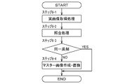
制御装置60は、薬剤の画像をマスター画像として蓄積した画像データベース62を備えている。制御装置60は、画像データベース62に登録されているマスター画像と、撮影装置40によって取得された薬剤の画像とをマッチングする画像マッチング処理を実行することにより、薬剤の数量及び種類のいずれか一方又は双方を薬剤情報として検出する薬品情報検出制御を実行可能である。以下、制御装置60によって実施される薬剤情報検出制御について先ず概略を説明した後、各工程において実施される制御について順を追って具体的に説明する。 ≪About drug inspection processing≫
The
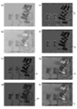
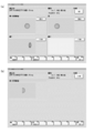
薬品情報検出制御は、正面側照明装置52をオン状態として撮影装置40により撮影された正面側照明画像と、背面側照明装置54をオン状態として撮影装置40により撮影された背面側照明画像とを用いて実施される。正面側照明画像は、図6(a)に示すように分包袋bを正面視した状態の画像であり、薬剤及び分包袋bに付されている印字とが写った画像となる。また、背面側照明画像は、図6(b)に示すように薬剤の影と分包袋bに付されている印字とが写った画像となる。制御装置60は、正面側照明画像及び背面側照明画像に基づき、分包袋b内に収容されている薬剤の画像を抽出し、この薬剤の画像に基づいて薬剤情報を検出する。 ≪Drug information detection control≫
In the medicine information detection control, the front side illumination image captured by the
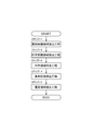
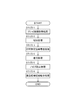
続いて、薬剤を画像鑑査する際に用いられる画像データベース62に登録されているマスター画像として、複数に分割した分割薬剤に関するものを作成する方法について説明する。制御装置60は、マスター画像作成手段64を備えている。マスター画像作成手段64は、画像データベース62に登録される薬剤の全体形状を示すマスター画像に基づき、この薬剤を複数に分割した分割薬剤についてのマスター画像を作成することができる。以下、マスター画像作成手段64による分割薬剤に係るマスター画像の作成方法について、図11に示したフローチャートを参照しつつ順を追って説明する。 ≪Master image creation method for divided medicine≫
Next, a method for creating a plurality of divided medicines related to a master image registered in the
続いて、撮影装置によって撮影した画像に基づいて作成されたマスター画像を、既登録のマスター画像と置換するマスター画像差し換え処理について説明する。マスター画像差し替え処理は、撮影装置40や照明装置50の個体差等に起因し、同一の薬剤について撮影を行っても色調等が異なる可能性を考慮し、薬剤の鑑査精度を向上させるために実施される処理である。すなわち、マスター画像差し替え処理は、画像データベース62に登録されているマスター画像と、実際に撮影装置によって撮影して得られる画像とで色調が相違する等して薬剤の特定がうまくいかないことを抑制するために実施されるものである。 ≪Master image replacement process≫
Next, a master image replacement process for replacing a master image created based on an image photographed by the photographing apparatus with a registered master image will be described. The master image replacement process is performed in order to improve the inspection accuracy of the medicine in consideration of the possibility that the color tone may be different even if the same medicine is photographed due to individual differences of the photographing
30 鑑査部
40 撮影装置
50 照明装置
52 正面側照明装置
54 背面側照明装置
60 制御装置
62 画像データベース
70 起立解消手段
A 薬剤候補領域
A2 縮小薬剤候補領域
B 印字候補領域
C 印字領域
X 薬剤領域 DESCRIPTION OF
Claims (8)
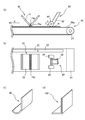
- 薬剤が分包袋内に収容された状態で配置される鑑査部と、
前記鑑査部に配置された前記分包袋を撮影可能な撮影装置と、
前記鑑査部に配置された前記分包袋を照明する照明装置と、
前記撮影装置によって得られた画像を用いて画像マッチング処理を行うことにより、薬剤の数量及び種類のいずれか一方又は双方を薬剤情報として検出する薬品情報検出制御を実行可能な制御手段とを備えており、
前記照明装置が、
前記鑑査部に配置された分包袋を前記撮影装置側から照射する正面側照明装置と、
前記分包袋を背面側から照射する背面側照明装置とを有し、
前記制御手段が、
前記正面側照明装置をオン状態として前記撮影装置により撮影された正面側照明画像と、前記背面側照明装置をオン状態として前記撮影装置により撮影された背面側照明画像とに基づき前記分包袋内に収容されている薬剤の画像を抽出し、当該薬剤の画像に基づいて薬剤情報を検出するものであり、
前記薬品情報検出制御が、
前記背面側照明画像において暗色の領域を薬剤の存在が想定される薬剤候補領域Aとして抽出する薬剤候補領域抽出工程と、
前記正面側照明画像に基づいて分包袋に付された印字が含まれている領域を印字候補領域Bとして抽出する印字候補領域抽出工程と、
前記背面側照明画像における輝度分布に基づき、前記印字候補領域Bに含まれている印字に相当する領域を印字領域Cとして特定する印字領域特定工程と、
前記薬剤候補領域Aから印字領域Cを差し引くことにより薬剤領域Xを導出する薬剤領域導出工程と、
を経て実施されることを特徴とする薬剤鑑査装置。 An inspection unit arranged in a state where the medicine is contained in a sachet;
A photographing device capable of photographing the sachet disposed in the inspection unit;
An illumination device for illuminating the sachet disposed in the inspection unit;
Control means capable of performing drug information detection control for detecting one or both of the quantity and type of medicine as medicine information by performing image matching processing using an image obtained by the imaging device. And
The lighting device is
A front side illumination device for irradiating a sachet arranged in the inspection unit from the imaging device side;
A back side illumination device that irradiates the packaging bag from the back side;
The control means is
Based on the front side illumination image photographed by the photographing device with the front side illumination device in the on state and the back side illumination image photographed by the photographing device with the back side illumination device in the on state The medicine image stored in the medicine is extracted, and the medicine information is detected based on the medicine image.
The drug information detection control is
A drug candidate region extraction step of extracting a dark region in the back side illumination image as a drug candidate region A in which the presence of a drug is assumed;
A print candidate area extraction step for extracting a print candidate area B as a print candidate area B including a print attached to the sachet based on the front side illumination image;
A printing area specifying step of specifying, as a printing area C, an area corresponding to printing included in the printing candidate area B based on the luminance distribution in the back side illumination image;
A drug region deriving step of deriving a drug region X by subtracting the print region C from the drug candidate region A;
It is carried out through the drug inspection device characterized by the above. - 前記薬剤候補領域抽出工程が、
前記背面側照明画像をグレイスケール化して背面照明グレイ画像を取得する処理と、
前記背面照明グレイ画像を二値化処理することにより分包袋に付された黒色の印字及び薬剤の存在が想定される印字・薬剤想定領域として特定する処理と、
前記背面照明グレイ画像をトップハット処理することにより得られたトップハット領域、及び前記背面照明グレイ画像をボトムハット処理することにより得られたボトムハット領域の和領域を印字の存在が想定される印字想定領域として導出する処理と、
を実施し、
前記印字・薬剤想定領域と前記印字想定領域との差分により、薬剤の存在が想定される薬剤候補領域Aを導出することを特徴とする請求項1に記載の薬剤鑑査装置。 The drug candidate region extraction step includes
Processing to grayscale the backside illumination image to obtain a backside illumination gray image;
A process of specifying the black print attached to the sachet bag by performing binarization processing on the back-illuminated gray image and the print / drug assumed area where the presence of the drug is assumed,
Printing that is assumed to be present in the top hat area obtained by top-hat processing of the back-lighted gray image and the sum area of the bottom hat area obtained by bottom-hat processing of the back-lighted gray image Processing to derive as an assumed area;
Carried out
The drug inspection apparatus according to claim 1, wherein a drug candidate area A in which a drug is assumed is derived based on a difference between the print / drug assumed area and the assumed print area. - 前記印字候補領域抽出工程が、
前記正面側照明画像をRGB分解して得られるRチャンネル画像、Gチャンネル画像、及びBチャンネル画像の各画像についてボトムハット処理を実施し、Rチャンネル画像、Gチャンネル画像、及びBチャンネル画像の全てにおいて黒色であると想定される領域を印字候補領域Bとして抽出するものであることを特徴とする請求項1又は2に記載の薬剤鑑査装置。 The printing candidate area extraction step includes
Bottom hat processing is performed on each of the R channel image, the G channel image, and the B channel image obtained by performing RGB decomposition on the front side illumination image, and all of the R channel image, the G channel image, and the B channel image are performed. The drug inspection device according to claim 1 or 2, wherein an area assumed to be black is extracted as a print candidate area B. - 前記印字領域特定工程が、
前記背面側照明画像をグレイスケール化した背面照明グレイ画像をトップハット処理することにより得られたトップハット領域、及び前記背面照明グレイ画像をボトムハット処理することにより得られたボトムハット領域の和領域として導出された印字想定領域から、前記印字領域Cを絞り込む工程であって、
前記正面側照明画像中の前記印字想定領域について輝度分布を分析し、文字に相当する領域と他の領域とを区別するための輝度の基準を規定する輝度基準規定処理と、
前記正面側照明画像をRGB分解して得られるRチャンネル画像、Gチャンネル画像、及びBチャンネル画像の全てにおいて黒色であると想定される印字候補領域Bを規定し、前記正面側照明画像中における前記印字候補領域B内に含まれている前記印字領域Cを、前記輝度基準規定処理によって規定された輝度の基準に基づき絞り込む絞込処理と、
を経て実行されることを特徴とする請求項1~3のいずれかに記載の薬剤鑑査装置。 The printing area specifying step includes
A top hat region obtained by top hat processing a back lighting gray image obtained by converting the back side lighting image into a gray scale, and a sum region of a bottom hat region obtained by bottom hat processing the back lighting gray image. A step of narrowing the print area C from the assumed print area derived as
A luminance reference defining process for analyzing a luminance distribution of the print assumed region in the front side illumination image and defining a luminance reference for distinguishing between a region corresponding to a character and another region;
A print candidate region B that is assumed to be black in all of the R channel image, the G channel image, and the B channel image obtained by performing RGB decomposition on the front side illumination image is defined, and the print candidate region B in the front side illumination image is defined. A narrowing-down process for narrowing down the print area C included in the print candidate area B based on the luminance standard defined by the luminance standard defining process;
The drug inspection device according to any one of claims 1 to 3, wherein the drug inspection device is executed through a process. - 前記薬剤領域導出工程において導出された薬剤領域Xに基づき、鑑査対象となる領域を規定する鑑査領域規定工程を有し、
前記鑑査領域規定工程が、
前記薬剤候補領域Aを縮小した縮小薬剤候補領域A2を導出する処理と、
前記薬剤領域Xと前記縮小薬剤候補領域A2との和領域を薬剤鑑査領域Zとして導出する処理と、
を経て実施されることを特徴とする請求項1~4のいずれかに記載の薬剤鑑査装置。 Based on the drug region X derived in the drug region derivation step, the inspection region defining step for defining the region to be inspected,
The inspection area defining step is:
A process of deriving a reduced drug candidate area A2 obtained by reducing the drug candidate area A;
A process of deriving a sum area of the drug area X and the reduced drug candidate area A2 as a drug inspection area Z;
The drug inspection device according to any one of claims 1 to 4, wherein the drug inspection device is implemented through the following. - 薬剤を撮影した画像をマスター画像として蓄積した画像データベースを用いて画像マッチング処理を実行可能なものであり、
前記画像データベースに登録される薬剤について、単一の薬剤を複数に分割した分割薬剤に係るマスター画像を、全体形状を示すマスター画像に基づいて作成可能なマスター画像作成手段を有し、
前記マスター画像作成手段が、
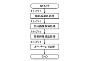
登録対象である薬剤を撮影した背面側照明画像に基づき薬剤の全体形状に係る輪郭線を導出する輪郭線導出処理と、
前記正面側照明画像において、前記輪郭線導出処理により得られた前記輪郭線の内部領域に対応する領域内の画像を、薬剤の全体形状に係る画像として取得する全体画像取得処理と、
前記正面側照明画像において、前記輪郭線導出処理により得られた前記輪郭線の外部領域の画像を背景画像として認識し、前記背景画像の平均輝度を導出する背景輝度導出処理と、
前記背景輝度導出処理で得られた前記背景画像に相当する輝度を有するマスキング画像を作成すると共に、前記全体画像取得処理により得られた薬剤の全体形状に係る画像の一部の領域に、前記マスキング画像を重複させるオーバーレイ処理と、
を実施することにより分割薬剤についてのマスター画像を作成可能であることを特徴とする請求項1~5のいずれかに記載の薬剤鑑査装置。 Image matching processing can be performed using an image database that stores images of drugs taken as master images,
A master image creating means capable of creating a master image related to a divided medicine obtained by dividing a single medicine into a plurality of medicines registered in the image database based on a master image indicating an overall shape,
The master image creating means
An outline deriving process for deriving an outline related to the overall shape of the drug based on the back side illumination image obtained by imaging the drug to be registered;
In the front side illumination image, an overall image acquisition process for acquiring an image in an area corresponding to an internal area of the outline obtained by the outline derivation process as an image related to the overall shape of the medicine;
In the front side illumination image, a background luminance derivation process for recognizing an image of an outer region of the outline obtained by the outline derivation process as a background image and deriving an average luminance of the background image;
A masking image having a luminance corresponding to the background image obtained by the background luminance derivation process is created, and the masking is applied to a partial region of the image related to the entire shape of the medicine obtained by the whole image acquisition process. Overlay processing that overlaps images,
6. The medicine inspection device according to claim 1, wherein a master image of the divided medicine can be created by performing the above. - 薬剤を撮影した画像をマスター画像として蓄積した画像データベースを用いて照合可能なものであり、
前記画像データベースに登録されている薬剤について、前記鑑査部に配置された所定の薬剤を前記撮影装置によって撮影した画像と、当該薬剤のマスター画像とを照合し、
前記制御手段により同一の薬剤でないとの判定がなされることを条件として、前記撮影装置によって撮影した画像に基づいて作成されたマスター画像を、既登録のマスター画像と置換可能であることを特徴とする請求項1~6のいずれかに記載の薬剤鑑査装置。 It is possible to collate using an image database that stores images of drugs taken as master images,
For a drug registered in the image database, an image obtained by photographing the predetermined medicine arranged in the inspection unit with the photographing device and a master image of the medicine are collated,
The master image created based on the image photographed by the photographing device can be replaced with a registered master image on condition that the control means determines that the medicines are not the same. The drug inspection device according to any one of claims 1 to 6. - 請求項1~7のいずれかに記載の薬剤鑑査装置と、
処方にあわせて薬剤を一包分ずつ分包袋に分包可能な薬剤分包装置とを備えており、
前記薬剤分包装置において分包された薬剤の個数を前記薬剤鑑査装置によって鑑査可能であることを特徴とする薬剤分包システム。 The drug inspection device according to any one of claims 1 to 7,
It is equipped with a medicine packaging device that can sachet the medicine one by one in accordance with the prescription,
The medicine packaging system, wherein the number of medicines packaged in the medicine packaging apparatus can be inspected by the medicine inspection apparatus.
Priority Applications (3)
| Application Number | Priority Date | Filing Date | Title |
|---|---|---|---|
| JP2014548610A JP6424624B2 (en) | 2012-11-22 | 2013-11-21 | Drug inspection device |
| US14/646,879 US9870611B2 (en) | 2012-11-22 | 2013-11-21 | Drug inspection device |
| EP13856758.1A EP2924647A4 (en) | 2012-11-22 | 2013-11-21 | Drug inspection device |
Applications Claiming Priority (2)
| Application Number | Priority Date | Filing Date | Title |
|---|---|---|---|
| JP2012256015 | 2012-11-22 | ||
| JP2012-256015 | 2012-11-22 |
Publications (1)
| Publication Number | Publication Date |
|---|---|
| WO2014080966A1 true WO2014080966A1 (en) | 2014-05-30 |
Family
ID=50776144
Family Applications (1)
| Application Number | Title | Priority Date | Filing Date |
|---|---|---|---|
| PCT/JP2013/081353 WO2014080966A1 (en) | 2012-11-22 | 2013-11-21 | Drug inspection device |
Country Status (4)
| Country | Link |
|---|---|
| US (1) | US9870611B2 (en) |
| EP (1) | EP2924647A4 (en) |
| JP (1) | JP6424624B2 (en) |
| WO (1) | WO2014080966A1 (en) |
Cited By (4)
| Publication number | Priority date | Publication date | Assignee | Title |
|---|---|---|---|---|
| JP2017194828A (en) * | 2016-04-20 | 2017-10-26 | 株式会社東芝 | Position detection device, position detection method and position detection program |
| JP2017192651A (en) * | 2016-04-22 | 2017-10-26 | 富士フイルム株式会社 | Audit support method and audit support apparatus |
| JPWO2018173649A1 (en) * | 2017-03-23 | 2019-12-12 | 富士フイルム富山化学株式会社 | Drug recognition device, drug recognition method, and drug recognition program |
| WO2020162263A1 (en) * | 2019-02-07 | 2020-08-13 | 富士フイルム富山化学株式会社 | Medical drug verification device, medical drug verification method, and medical drug verification system |
Families Citing this family (5)
| Publication number | Priority date | Publication date | Assignee | Title |
|---|---|---|---|---|
| FR3077907B1 (en) * | 2018-02-13 | 2021-06-18 | Pharmed S A M | INSTALLATION AND PROCEDURE FOR DETECTION OF THE CONTOUR, AND LOCATION OF A THREE-DIMENSIONAL PRODUCT BASED IN THE LOCATION OR UPside down ON A SURFACE |
| KR20200138921A (en) | 2019-06-03 | 2020-12-11 | 삼성전자주식회사 | Apparatus and method for identifying pharmaceutical |
| JP7427684B2 (en) * | 2019-10-01 | 2024-02-05 | 富士フイルム富山化学株式会社 | Drug verification system, drug management method and program |
| EP4107516A4 (en) * | 2020-02-21 | 2024-04-03 | Applied Materials Inc | Method and system for inspection of products |
| CN112883958B (en) * | 2021-01-11 | 2023-12-05 | 壹药网科技(上海)股份有限公司 | Medicine goods space checking method |
Citations (3)
| Publication number | Priority date | Publication date | Assignee | Title |
|---|---|---|---|---|
| JPH07200770A (en) | 1993-12-28 | 1995-08-04 | Sanyo Electric Co Ltd | Tablet inspection system |
| JPH07209196A (en) * | 1994-01-17 | 1995-08-11 | Sanyo Electric Co Ltd | Tablet inspection system |
| WO2012147907A1 (en) * | 2011-04-28 | 2012-11-01 | 株式会社湯山製作所 | Medicine checking device and apparatus for separately packaging medicines |
Family Cites Families (20)
| Publication number | Priority date | Publication date | Assignee | Title |
|---|---|---|---|---|
| DE3784884T2 (en) * | 1986-12-29 | 1993-06-24 | Fujimori Kogyo Co | METHOD AND DEVICE FOR CHECKING THE CONTENT OF PACKED PRODUCTS. |
| US6330351B1 (en) * | 1996-11-29 | 2001-12-11 | Kabushiki Kaisha Yuyama Seisakusho | Drug inspection device and drug packaging device |
| JPH10320502A (en) * | 1997-05-20 | 1998-12-04 | Matsushita Electric Ind Co Ltd | Component character collation and inspection method, and component character collation and inspection device |
| JPH11144057A (en) * | 1997-11-12 | 1999-05-28 | Ricoh Co Ltd | Device and method for image recognition |
| US6324253B1 (en) * | 1998-08-26 | 2001-11-27 | Yuyama Mfg. Co., Ltd. | Tablet inspection apparatus |
| NL1022679C1 (en) * | 2003-02-14 | 2004-08-17 | Dijkstra Vereenigde Bedrijven | Inspection device for loose objects, such as tablets. |
| NL1025161C1 (en) * | 2003-08-19 | 2005-07-04 | Global Factories B V | Drug inspection method in large pharmacy, involves grouping number of packs each including several drugs, to form string in association with patient data, and storing scanned image of packs and patient data in memory |
| US9334096B2 (en) * | 2004-10-01 | 2016-05-10 | Edge Medical Properties, Llc | Multiple inspection system and method that inspects different medications |
| KR100650285B1 (en) * | 2005-05-25 | 2006-11-27 | (주)제이브이엠 | System for inspecting medicine packets |
| JP4159577B2 (en) * | 2005-12-13 | 2008-10-01 | ファナック株式会社 | Interlock automatic setting device and automatic setting method between a plurality of robots |
| NL1032492C2 (en) * | 2006-09-14 | 2008-03-17 | Dijkstra Vereenigde Bedrijven | Inspection device. |
| CN101678960B (en) * | 2007-06-19 | 2011-11-02 | 快力胶囊股份有限公司 | Vibration feeder, carrier and visual inspection apparatus |
| JP4168428B1 (en) * | 2007-06-19 | 2008-10-22 | クオリカプス株式会社 | Inspected object conveying device and appearance inspection device |
| US20090055116A1 (en) * | 2007-08-24 | 2009-02-26 | Chou-Pi Chen | Method For Inspecting Appearance Of Pellet Type Medicines And System Employing Thereof |
| US20100170206A1 (en) * | 2009-01-06 | 2010-07-08 | Jvm Co., Ltd. | Medicine pouch arranging device |
| US8146331B2 (en) * | 2009-01-15 | 2012-04-03 | Sabrie Soloman | Automated packaging, inspection, verification, and counting apparatus |
| EP2381246A1 (en) * | 2010-04-26 | 2011-10-26 | Becton Dickinson France | Device, kit and method for inspection of an article |
| EP2591761A1 (en) | 2010-07-09 | 2013-05-15 | Panasonic Corporation | Tablet inspection assistance method and tablet inspection assistance system |
| US8215557B1 (en) * | 2010-11-18 | 2012-07-10 | Innovation Associates, Inc. | Low profile color-based counting system |
| US20120293623A1 (en) * | 2011-05-17 | 2012-11-22 | Gii Acquisition, Llc Dba General Inspection, Llc | Method and system for inspecting small manufactured objects at a plurality of inspection stations and sorting the inspected objects |
-
2013
- 2013-11-21 WO PCT/JP2013/081353 patent/WO2014080966A1/en active Application Filing
- 2013-11-21 JP JP2014548610A patent/JP6424624B2/en active Active
- 2013-11-21 US US14/646,879 patent/US9870611B2/en active Active
- 2013-11-21 EP EP13856758.1A patent/EP2924647A4/en not_active Withdrawn
Patent Citations (3)
| Publication number | Priority date | Publication date | Assignee | Title |
|---|---|---|---|---|
| JPH07200770A (en) | 1993-12-28 | 1995-08-04 | Sanyo Electric Co Ltd | Tablet inspection system |
| JPH07209196A (en) * | 1994-01-17 | 1995-08-11 | Sanyo Electric Co Ltd | Tablet inspection system |
| WO2012147907A1 (en) * | 2011-04-28 | 2012-11-01 | 株式会社湯山製作所 | Medicine checking device and apparatus for separately packaging medicines |
Non-Patent Citations (1)
| Title |
|---|
| See also references of EP2924647A4 |
Cited By (7)
| Publication number | Priority date | Publication date | Assignee | Title |
|---|---|---|---|---|
| JP2017194828A (en) * | 2016-04-20 | 2017-10-26 | 株式会社東芝 | Position detection device, position detection method and position detection program |
| JP2017192651A (en) * | 2016-04-22 | 2017-10-26 | 富士フイルム株式会社 | Audit support method and audit support apparatus |
| US10937152B2 (en) | 2016-04-22 | 2021-03-02 | Fujifilm Toyama Chemical Co., Ltd. | Inspection support method and inspection support device |
| JPWO2018173649A1 (en) * | 2017-03-23 | 2019-12-12 | 富士フイルム富山化学株式会社 | Drug recognition device, drug recognition method, and drug recognition program |
| WO2020162263A1 (en) * | 2019-02-07 | 2020-08-13 | 富士フイルム富山化学株式会社 | Medical drug verification device, medical drug verification method, and medical drug verification system |
| CN113260344A (en) * | 2019-02-07 | 2021-08-13 | 富士胶片富山化学株式会社 | Drug comparison device, drug comparison method, and drug comparison system |
| JPWO2020162263A1 (en) * | 2019-02-07 | 2021-11-04 | 富士フイルム富山化学株式会社 | Drug matching device, drug matching method and drug matching system |
Also Published As
| Publication number | Publication date |
|---|---|
| JP6424624B2 (en) | 2018-11-21 |
| JPWO2014080966A1 (en) | 2017-01-05 |
| US20160005160A1 (en) | 2016-01-07 |
| EP2924647A1 (en) | 2015-09-30 |
| US9870611B2 (en) | 2018-01-16 |
| EP2924647A4 (en) | 2016-08-31 |
Similar Documents
| Publication | Publication Date | Title |
|---|---|---|
| WO2014080966A1 (en) | Drug inspection device | |
| JP5196285B1 (en) | Drug inspection device and drug packaging device | |
| JP6100136B2 (en) | Drug recognition apparatus and method | |
| US10726285B2 (en) | Medicine audit apparatus, method, and program | |
| CN110892445B (en) | Drug inspection support device, drug identification device, image processing method, and program | |
| CN111052145B (en) | Drug inspection support device, image processing device, and image processing method | |
| CN111031995A (en) | Medicine inspection support device, image processing method, and program | |
| JP2006194801A (en) | Appearance inspection apparatus and ptp wrapping machine | |
| CN114450677A (en) | Drug matching device, drug matching system, drug management method, and program | |
| JPH07204253A (en) | Tablet inspection system | |
| JP2014221134A (en) | Packaged single-dose-medicament auditing device | |
| CN110892413A (en) | Drug identification device, image processing method, and program | |
| JP4201143B2 (en) | Appearance inspection device and PTP packaging machine equipped with appearance inspection device | |
| JP7375049B2 (en) | Image processing device and method | |
| JP4251325B2 (en) | Appearance inspection device and PTP packaging machine | |
| JP2010121941A (en) | Inspection apparatus and method for print position displacement | |
| JP2021010712A (en) | Medicament screening device | |
| JP2021133238A (en) | Medicine inspection device |
Legal Events
| Date | Code | Title | Description |
|---|---|---|---|
| 121 | Ep: the epo has been informed by wipo that ep was designated in this application |
Ref document number: 13856758 Country of ref document: EP Kind code of ref document: A1 |
|
| ENP | Entry into the national phase |
Ref document number: 2014548610 Country of ref document: JP Kind code of ref document: A |
|
| NENP | Non-entry into the national phase |
Ref country code: DE |
|
| WWE | Wipo information: entry into national phase |
Ref document number: 2013856758 Country of ref document: EP |
|
| WWE | Wipo information: entry into national phase |
Ref document number: 14646879 Country of ref document: US |