WO2014080568A1 - Procédé permettant d'émettre et de recevoir des données - Google Patents
Procédé permettant d'émettre et de recevoir des données Download PDFInfo
- Publication number
- WO2014080568A1 WO2014080568A1 PCT/JP2013/006200 JP2013006200W WO2014080568A1 WO 2014080568 A1 WO2014080568 A1 WO 2014080568A1 JP 2013006200 W JP2013006200 W JP 2013006200W WO 2014080568 A1 WO2014080568 A1 WO 2014080568A1
- Authority
- WO
- WIPO (PCT)
- Prior art keywords
- data
- transmission
- node
- transmitted
- information
- Prior art date
Links
- 238000000034 method Methods 0.000 title claims abstract description 67
- 230000005540 biological transmission Effects 0.000 claims abstract description 301
- 230000000737 periodic effect Effects 0.000 claims description 28
- 230000004044 response Effects 0.000 description 41
- 239000002699 waste material Substances 0.000 description 16
- 239000000872 buffer Substances 0.000 description 15
- 238000010586 diagram Methods 0.000 description 10
- 238000001514 detection method Methods 0.000 description 7
- 230000002093 peripheral effect Effects 0.000 description 4
- 230000015572 biosynthetic process Effects 0.000 description 1
- 239000000284 extract Substances 0.000 description 1
- 230000004622 sleep time Effects 0.000 description 1
Images

Classifications
-
- H—ELECTRICITY
- H04—ELECTRIC COMMUNICATION TECHNIQUE
- H04L—TRANSMISSION OF DIGITAL INFORMATION, e.g. TELEGRAPHIC COMMUNICATION
- H04L12/00—Data switching networks
- H04L12/02—Details
- H04L12/12—Arrangements for remote connection or disconnection of substations or of equipment thereof
-
- H—ELECTRICITY
- H04—ELECTRIC COMMUNICATION TECHNIQUE
- H04L—TRANSMISSION OF DIGITAL INFORMATION, e.g. TELEGRAPHIC COMMUNICATION
- H04L12/00—Data switching networks
- H04L12/28—Data switching networks characterised by path configuration, e.g. LAN [Local Area Networks] or WAN [Wide Area Networks]
- H04L12/40—Bus networks
- H04L12/403—Bus networks with centralised control, e.g. polling
-
- H—ELECTRICITY
- H04—ELECTRIC COMMUNICATION TECHNIQUE
- H04L—TRANSMISSION OF DIGITAL INFORMATION, e.g. TELEGRAPHIC COMMUNICATION
- H04L12/00—Data switching networks
- H04L12/28—Data switching networks characterised by path configuration, e.g. LAN [Local Area Networks] or WAN [Wide Area Networks]
- H04L12/44—Star or tree networks
-
- H—ELECTRICITY
- H04—ELECTRIC COMMUNICATION TECHNIQUE
- H04L—TRANSMISSION OF DIGITAL INFORMATION, e.g. TELEGRAPHIC COMMUNICATION
- H04L41/00—Arrangements for maintenance, administration or management of data switching networks, e.g. of packet switching networks
- H04L41/12—Discovery or management of network topologies
-
- H—ELECTRICITY
- H04—ELECTRIC COMMUNICATION TECHNIQUE
- H04L—TRANSMISSION OF DIGITAL INFORMATION, e.g. TELEGRAPHIC COMMUNICATION
- H04L67/00—Network arrangements or protocols for supporting network services or applications
- H04L67/01—Protocols
- H04L67/10—Protocols in which an application is distributed across nodes in the network
- H04L67/104—Peer-to-peer [P2P] networks
-
- H—ELECTRICITY
- H04—ELECTRIC COMMUNICATION TECHNIQUE
- H04W—WIRELESS COMMUNICATION NETWORKS
- H04W28/00—Network traffic management; Network resource management
- H04W28/02—Traffic management, e.g. flow control or congestion control
- H04W28/04—Error control
-
- H—ELECTRICITY
- H04—ELECTRIC COMMUNICATION TECHNIQUE
- H04W—WIRELESS COMMUNICATION NETWORKS
- H04W28/00—Network traffic management; Network resource management
- H04W28/02—Traffic management, e.g. flow control or congestion control
- H04W28/06—Optimizing the usage of the radio link, e.g. header compression, information sizing, discarding information
- H04W28/065—Optimizing the usage of the radio link, e.g. header compression, information sizing, discarding information using assembly or disassembly of packets
-
- H—ELECTRICITY
- H04—ELECTRIC COMMUNICATION TECHNIQUE
- H04W—WIRELESS COMMUNICATION NETWORKS
- H04W52/00—Power management, e.g. Transmission Power Control [TPC] or power classes
- H04W52/02—Power saving arrangements
-
- H—ELECTRICITY
- H04—ELECTRIC COMMUNICATION TECHNIQUE
- H04W—WIRELESS COMMUNICATION NETWORKS
- H04W52/00—Power management, e.g. Transmission Power Control [TPC] or power classes
- H04W52/02—Power saving arrangements
- H04W52/0209—Power saving arrangements in terminal devices
- H04W52/0212—Power saving arrangements in terminal devices managed by the network, e.g. network or access point is leader and terminal is follower
- H04W52/0216—Power saving arrangements in terminal devices managed by the network, e.g. network or access point is leader and terminal is follower using a pre-established activity schedule, e.g. traffic indication frame
-
- H—ELECTRICITY
- H04—ELECTRIC COMMUNICATION TECHNIQUE
- H04W—WIRELESS COMMUNICATION NETWORKS
- H04W52/00—Power management, e.g. Transmission Power Control [TPC] or power classes
- H04W52/02—Power saving arrangements
- H04W52/0209—Power saving arrangements in terminal devices
- H04W52/0212—Power saving arrangements in terminal devices managed by the network, e.g. network or access point is leader and terminal is follower
- H04W52/0219—Power saving arrangements in terminal devices managed by the network, e.g. network or access point is leader and terminal is follower where the power saving management affects multiple terminals
-
- H—ELECTRICITY
- H04—ELECTRIC COMMUNICATION TECHNIQUE
- H04W—WIRELESS COMMUNICATION NETWORKS
- H04W52/00—Power management, e.g. Transmission Power Control [TPC] or power classes
- H04W52/02—Power saving arrangements
- H04W52/0209—Power saving arrangements in terminal devices
- H04W52/0225—Power saving arrangements in terminal devices using monitoring of external events, e.g. the presence of a signal
- H04W52/0229—Power saving arrangements in terminal devices using monitoring of external events, e.g. the presence of a signal where the received signal is a wanted signal
-
- H—ELECTRICITY
- H04—ELECTRIC COMMUNICATION TECHNIQUE
- H04W—WIRELESS COMMUNICATION NETWORKS
- H04W56/00—Synchronisation arrangements
-
- H—ELECTRICITY
- H04—ELECTRIC COMMUNICATION TECHNIQUE
- H04W—WIRELESS COMMUNICATION NETWORKS
- H04W68/00—User notification, e.g. alerting and paging, for incoming communication, change of service or the like
-
- H—ELECTRICITY
- H04—ELECTRIC COMMUNICATION TECHNIQUE
- H04W—WIRELESS COMMUNICATION NETWORKS
- H04W84/00—Network topologies
- H04W84/18—Self-organising networks, e.g. ad-hoc networks or sensor networks
-
- Y—GENERAL TAGGING OF NEW TECHNOLOGICAL DEVELOPMENTS; GENERAL TAGGING OF CROSS-SECTIONAL TECHNOLOGIES SPANNING OVER SEVERAL SECTIONS OF THE IPC; TECHNICAL SUBJECTS COVERED BY FORMER USPC CROSS-REFERENCE ART COLLECTIONS [XRACs] AND DIGESTS
- Y02—TECHNOLOGIES OR APPLICATIONS FOR MITIGATION OR ADAPTATION AGAINST CLIMATE CHANGE
- Y02D—CLIMATE CHANGE MITIGATION TECHNOLOGIES IN INFORMATION AND COMMUNICATION TECHNOLOGIES [ICT], I.E. INFORMATION AND COMMUNICATION TECHNOLOGIES AIMING AT THE REDUCTION OF THEIR OWN ENERGY USE
- Y02D30/00—Reducing energy consumption in communication networks
- Y02D30/70—Reducing energy consumption in communication networks in wireless communication networks
Definitions
- the present invention relates to a data transmission / reception method capable of effectively suppressing waste of electric power.
- the wireless personal area network is a short-distance network that enables interconnection between devices in a personal work environment and devices in the vicinity thereof.
- a network conforming to the IEEE802.15.4 standard is roughly composed of two types of devices, FFD (Full Function Device) and RFD (Reduced Function Device).
- the FFD is a full-featured device having a function for approving a PAN to a new device that intends to join a personal area network (PAN) to which the FFD belongs, and a function for defining a superframe used in communication with other devices. .
- PAN personal area network
- a PAN coordinator one that exists in each network and further has a function of determining the ID of the entire network.
- RFD is a device that does not have the above-mentioned subscription approval function and superframe definition function that FFD has, and is a function-restricted device that has the same functions as FFD, except that these functions are not provided.
- FIG. 7 is a schematic diagram showing the topology of a conventional network configured by FFD and RFD. As shown in FIG. 7, as the topology of such a network, there are topologies such as a star network (FIG. 7A), a peer-to-peer network (FIG. 7B), and the like.
- FIG. 7A star network
- FIG. 7B peer-to-peer network
- the star network is composed of a PAN coordinator and multiple FFDs or RFDs. A master-slave relationship is established between all devices (see Patent Document 1). Then, a synchronization signal (beacon) is periodically transmitted from the FFD, which is the master located at the upper level, to the FDD or RFD, which is the slave at the lower level, thereby establishing synchronization between the master and the slave. Information is transmitted and received by a TDMA (Time Division Multiple Access) method.
- TDMA Time Division Multiple Access
- the peer-to-peer network is similar to the star network described above in that it is composed of a PAN coordinator and a plurality of FFDs or RFDs, but all devices are equivalent, that is, a master-slave relationship is established between the devices. It is different in that it is not.
- Information transmission / reception is performed between devices constituting the peer-to-peer network by a CSMA (Carrier-Sense-Multiple-Access) method.
- CSMA Carrier-Sense-Multiple-Access
- the FFD performs time synchronization for communication in the communication network, approval for participation in the communication network, and approval for removal from the communication network, and also centralizes the setting of sleep time for power saving. To manage. Therefore, it is essential for the communication network to have at least one FFD, and this has been a factor that hinders the formation of a flexible communication network.
- the present invention has been devised in view of the above-described problems, and can transmit and receive information even when no FFD exists, and can effectively suppress waste of power.
- An object is to provide a data transmission / reception method.
- the present inventor has invented a data transmission / reception method capable of effectively suppressing power consumption in order to solve the above-described problems.
- the data transmission / reception method according to claim 1 of the present application is a data transmission / reception method between a plurality of nodes, and is performed in one node to determine whether or not the data size of transmission target data is equal to or smaller than a transmittable data size.
- a data transmission / reception method is the data transmission / reception method according to claim 1, wherein the division header includes information defining an arrangement order of the intermediate data. .
- the data transmission / reception method according to claim 3 of the present application is a data transmission / reception method between nodes, and the data size of each of a plurality of transmission target data performed in one node is equal to or less than a transmittable data size.
- the transmission data is divided based on information of header parts of the plurality of transmission target data included in the transmission data, and the plurality of transmission targets It characterized in that it comprises a restoring step of restoring the over data, the.
- the data transmission / reception method is a data transmission / reception method between nodes in which a plurality of nodes periodically waits at a specific interval, and one node can communicate with other nodes that can communicate with each other.
- the other node that has received the advance notice information waits for data in accordance with the data transmission timing indicated in the advance notice information, and the one node transmits the data size of the transmission target data.
- a determination step of determining whether or not the data size is less than or equal to a possible data size, and the one node can transmit the transmission target data larger than a data size that can be transmitted A dividing step of dividing the data into a plurality of intermediate data having a data size equal to or smaller than a data size, and a transmission data generating step of generating a plurality of transmission data by adding a division header to each of the plurality of intermediate data by the one node.
- the one node transmits a plurality of transmission data to the other node according to the data transmission timing of the announcement information, and the other node transmits the one data according to the notification data transmission timing.
- the data transmission / reception method is a data transmission / reception method between nodes in which a plurality of nodes periodically waits at a specific interval, and one node can communicate with other nodes that can communicate with each other.
- a detecting step for detecting, and the other node transmits standby information indicating the timing of performing the periodic standby to the one node continuously to the periodic standby before the periodic standby.
- a standby information receiving step for receiving reception information, a determination step for determining whether or not the data size of the transmission target data is equal to or smaller than a data size that can be transmitted, and the one node A division step of dividing the transmission target data larger than the transmittable data size into a plurality of intermediate data having a data size equal to or smaller than the transmittable data size, and the one node is divided into each of the plurality of intermediate data
- a data transmission step of transmitting the data, a data reception step of receiving a plurality of the transmission data transmitted from the one node during the periodic standby, and the other node received For a plurality of the transmission data, a restoration step of integrating the transmission data based on the information of the division header and restoring the transmission target data. Characterized in that it obtain.
- the data transmission / reception method is a data transmission / reception method between nodes in which a plurality of nodes periodically waits at a specific interval, and one node can communicate with other nodes that can communicate with each other.
- a standby information transmission step in which the other node that has received the standby information request from the one node transmits the standby information to the one node; and Sent from the node A standby information receiving step of receiving the standby information, a determination step of determining whether or not the data size of the transmission target data is equal to or smaller than a transmittable data size, and the one node A division step of dividing the transmission target data larger than the transmittable data size into a plurality of intermediate data having a data size equal to or smaller than the transmittable data size, and the one node is configured to each of the plurality of intermediate data
- a transmission data generation step of generating a plurality of transmission data by adding a division header to the first node, and the one node transmits the plurality of transmissions to the other node according to the timing indicated in the received standby information.
- a data transmission step for transmitting data; and the other node receives a plurality of the transmission data transmitted from the one node during the periodic standby.
- a data receiving step, and the other node comprises a restoration step of integrating the transmission data based on the information of the division header and restoring the transmission target data for the plurality of transmission data received.
- data can be combined based on the information of the divided header part included in the transmission data, and the original transmission target data can be restored.
- FIG. 5 is a diagram showing a state of data transmission / reception between nodes in the data transmission / reception method according to the first embodiment of the present invention. It is a figure which shows the mode of the data transmission / reception between nodes in the data transmission / reception method which concerns on 2nd Embodiment of this invention.
- FIG. 6 is a schematic diagram showing the topology of a conventional network configured by FFD and RFD.
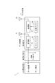
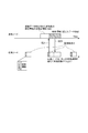
- FIG. 1 is a diagram illustrating a node structure in the data transmission / reception method according to the embodiment.
- the node 1 includes a radio unit 2, a communication control unit 3, and an upper layer processing unit 4.
- a node is a generic name for devices that transmit and receive data, such as data transmission and relay including FFD and RFD.
- the radio unit 2 includes a receiving unit 22 that receives data via the receiving antenna 21, a transmitting unit 24 that transmits data via the transmitting antenna 23, a main buffer 25 that buffers various data, and a transmission with the main buffer 25.
- a transmission buffer 26 is provided between the main buffer 25 and the transmission buffer 26 to buffer transmission data sent from the main buffer 25 to the transmission unit 24.
- the communication control unit 3 is provided between the radio unit 2 and the upper layer processing unit 4 and controls the entire radio communication by the radio unit 2.
- the communication control unit 3 extracts the payload included in the data received by the reception unit 22 via the reception antenna 21, determines the processing to be performed for each of the payloads, and determines each payload according to the determination result.
- the data is transmitted to the main buffer 25 and the upper layer processing unit 4.
- the upper layer processing unit 4 performs various processes on the received data and generates various data related to data transmission / reception such as a new payload.
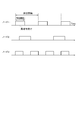
- FIG. 2 is a diagram illustrating a state in which each node 1 periodically waits in the data transmission / reception method according to each embodiment of the present invention. Note that the periodic standby of each node shown in FIG. 2 is also performed in other embodiments described later.
- each node waits periodically with a unique standby period and a specific interval. In this way, each node is not always in a standby state, that is, not always in a power-on state, but intermittently enters a standby state, thereby preventing waste of power.
- synchronization is not established between the nodes, but the data transmission / reception method according to the present invention enables transmission / reception of data between the nodes even under such circumstances.
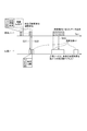
- FIG. 3 is a diagram illustrating a manner in which peripheral nodes are detected in the data transmission / reception method according to the present embodiment.
- a node that detects a communicable node in the vicinity waits for a data modulation method and data reception employed.
- Transmission of information unique to the request node (hereinafter referred to as “node information”) such as timing and data reception standby are repeated at predetermined intervals (step S1).
- node information such as timing and data reception standby are repeated at predetermined intervals (step S1).
- the node information transmission and the data reception standby are collectively referred to as a discovery operation.
- step S2 another node in the vicinity of the request node and periodically waiting at its own interval receives the node information transmitted from the request node during this periodic waiting (step S2). ).
- response nodes 1 and 2 there are two nodes (hereinafter referred to as “response nodes 1 and 2”) around the request node, and these two response nodes 1 and 2 receive node information from the request node. .
- node information is repeatedly transmitted in a discovery operation periodically performed by the request node, while the response nodes 1 and 2 If the standby is repeated repeatedly, the transmission timing of the node information from the requesting node may coincide with the standby timing of the response nodes 1 and 2. As a result of the coincidence of both timings, information can be transmitted and received even between nodes where synchronization is not established.
- the response nodes 1 and 2 having received the node information transmitted from the request node transmit their own node information to the request node, and the request node is a node transmitted from the response nodes 1 and 2.
- Information is received while waiting for reception included in the above-described discovery operation (step S3).
- the exchange of node information between the request node and the response nodes 1 and 2 completes the detection of the response nodes 1 and 2 by the request node. Thereafter, when information is transmitted and received between the request node and the response nodes 1 and 2, a data modulation method suitable for each node is selected based on the node information.
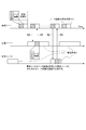
- FIG. 4 is a diagram illustrating a state of data transmission / reception between nodes in the data transmission / reception method according to the first embodiment of the present invention.
- the requesting node transmits notice information indicating the data transmission timing to the response node continuously several times at predetermined intervals, such as how many seconds from now on, to transmit data (step S11).
- the number of continuous transmissions of the advance notice information is performed a sufficient number of times over one period of periodic waiting of the response node. This is to increase the probability that the response node receives the advance notice information.
- the advance transmission of the advance notice information is performed a number of times in one cycle, the response node reliably receives the advance notice information. Will be able to.
- the data transmission timing included in each notice information becomes shorter from the notice information sent first.
- the data transmission timing included in the first notice information is “10 seconds after the current time”, and the notice information is transmitted after 0.5 seconds.
- the transmission of the next notice information is started after one second after the interval of 0.5 seconds, the data transmission timing included in the next notice information is “9 seconds after the current time.
- the response node that periodically waits at a specific interval receives the advance notice information transmitted from the request node (step S12).
- the number of continuous transmissions of the notice information is performed as many times as one period of the periodic standby of the response node, so that the response node can reliably receive the notice information.
- the response node that has received the advance notice information waits for data according to the data transmission timing indicated in the received advance notice information, and the transmission node performs data transmission according to the data transmission timing indicated in the advance notice information.
- the response node receives the data (step S13). Thus, transmission / reception of a series of data is completed.
- information can be transmitted / received even in a situation where there is no FFD and synchronization is not established between the nodes 1.
- each node 1 does not always wait, but waits intermittently, and is activated only during the time indicated in the data transmission timing during data transmission / reception, so that data can be waited, transmitted, and received. The waste of electric power can be effectively suppressed.
- each node 1 performs periodic standby with a specific standby period and a specific interval, as in the first embodiment. Yes.
- the detection method of the surrounding node 1 in this embodiment is performed like the thing in 1st Embodiment mentioned above, and a request
- FIG. 5 is a diagram illustrating a state of data transmission / reception between nodes 1 in the data transmission / reception method according to the second embodiment of the present invention.
- the response node transmits standby information indicating the timing of performing its own periodic standby to the requesting node continuously before the periodic standby (step S21).
- the standby information is transmitted repeatedly in the same cycle as the periodic standby by continuously transmitting the periodic standby.
- the request node waits at the same time as generating data to be transmitted to the request node (step S22).
- the request node When the request node receives the standby information transmitted from the response node during the standby, the request node follows the timing of performing the periodic standby of the response node indicated in the received standby information.
- the generated data is transmitted to the response node, and the response node receives the data (step S23).
- the response node since the data transmitted from the request node is transmitted during the periodic standby of the response node, the response node receives the data during the periodic standby. Thus, transmission / reception of a series of data is completed.
- information can be transmitted / received even in a situation where there is no FFD and synchronization is not established between the nodes 1.
- each node 1 does not always wait, intermittently waits, and starts only during the time indicated in the data reception timing during data transmission / reception, and performs data standby, transmission, and reception. Therefore, waste of electric power can be effectively suppressed.
- each node 1 performs periodic standby with a specific standby period and a specific interval, as in the first embodiment. Yes.
- the detection method of the surrounding node 1 in this embodiment is performed like the thing in 1st Embodiment mentioned above, and a request
- FIG. 6 is a diagram illustrating a state of data transmission / reception between nodes 1 in the data transmission / reception method according to the third embodiment of the present invention.
- the request node transmits a standby information request for requesting standby information indicating the timing at which the response node periodically performs standby to the response node several times at predetermined intervals, and multiple times.
- standby information is waited for from a response node described later (step S31).
- the response node can reliably receive the standby information request by performing the number of continuous transmissions of the standby information request for the number of times over one cycle of the periodic standby of the response node. preferable.
- the response node that has received the standby information request from the request node transmits the standby information to the request node in response to the request (step S32).
- the requesting node can grasp the periodic standby timing of the response node based on the standby information received from the response node.
- the request node transmits data to the response node at the periodic standby timing of the response node thus grasped, and the response node receives data transmitted from the request node during the periodic standby. (Step S33).
- information can be transmitted / received even in a situation where there is no FFD and synchronization is not established between the nodes 1.
- each node 1 does not always wait, intermittently waits, and starts only during the time indicated in the data reception timing during data transmission / reception, and performs data standby, transmission, and reception. Therefore, waste of electric power can be effectively suppressed.
- data transmission / reception between nodes may not be completed within the initially specified standby time. In such a case, the data transmission / reception does not need to be completed within the standby time. If the data transmission / reception is not completed within the standby time, the data transmission / reception is completed until the completion of the standby time. Continued.
- the standby time can be shortened, and the time that each node can be in the sleep mode can be lengthened, so that the power consumption of each node can be effectively suppressed.
- the data size of the transmission data generated in the upper layer processing unit 4 of each node 1 that performs data transmission, and the frequency and power when performing data transmission may be different (see FIG. 1).
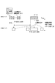
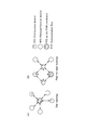
- FIG. 7A and 7B are diagrams showing (A) a state of data division and (B) a state of data combination in the data transmission / reception method according to each embodiment of the present invention.
- the generated data 11 stored in the transmission buffer 26 of the wireless unit 2, which is transmission target data generated in the higher layer processing unit 4, is used for various processes in the higher processing unit 4.
- the header part 11a is provided for use, and an information part 11b which is a data body to be transmitted to another node.
- the generation data 11 generated by the upper layer processing unit 4 is described as an example of transmission target data.
- the present invention is not limited to this, and data that is not generated at this node is not limited to this. That is, it may be data to be relayed that is received from another node and further transmitted to another node.
- the communication control unit 3 determines whether or not the generated data 11 has a data size 12 or less that can be transmitted by the transmission unit 24. Since the generated data 11 is larger than the data size 12 that can be transmitted by the transmission unit 24, data transmission cannot be performed smoothly or cannot be performed as it is. Then, repeating this transmission process until success causes an increase in power consumption.
- the communication control unit 3 of each node divides the generated data 11 into a plurality of intermediate data.
- the communication control unit 3 divides the generated data 11 into two intermediate data 13 and 14 having a data size equal to or smaller than the data size that can be transmitted.
- the intermediate data 13 has a header portion 13a out of two data generated so as to be divided into two at the information portion 11b.
- the other data generated by the division is intermediate data 14. It becomes.
- the communication control unit 3 adds the divided header portions 15a and 15b to the intermediate data 13 and 14, respectively, and generates transmission data 15 and 16 that are divided data in a format that is actually transmitted.
- the division header parts 15a and 15b indicate data 151 indicating the presence / absence of subsequent information of transmission data and information indicating how many pieces of transmission data 15, 16,...
- data 152 indicating the number of divisions
- data 153 indicating the number of divisions when viewed from the header portion 11a
- four pieces of information 154 indicating the sequence number of the original information portion 11b of the information portions 13b and 14b Consists of data.
- the communication control unit 3 of each node generates transmission data 15 and 16 by dividing the generation data 11. At this time, the communication control unit 3 sequentially generates intermediate data and transmission data so that the generated transmission data 15 and 16 have a size equal to or smaller than the data size requested by the transmission unit 24 that controls transmission of actual information. Go.
- the generated transmission data 15 and 16 are sent again from the communication control unit 3 to the transmission unit 24 through the main buffer 25 and the transmission buffer 26 and transmitted to the other nodes 1.
- transmission of these data is performed smoothly without delay.
- the communication control unit 3 of the other node 1 that has received the transmission data 15 and 16 combines these data based on the information of the divided header units 15a and 16a included in the transmission data 15 and 16, and generates the original data.
- the data 11 is restored. This data combination will be specifically described below.
- the data 151 indicating the presence / absence of the subsequent information is “present”, and the data 152 indicating the number of divisions is divided into two.
- the data 153 shown is defined as “1”.
- the data 151 indicating the presence / absence of subsequent information is “None”, and the data 152 indicating the number of divisions is divided into two.
- the data 153 shown is defined as “2”.
- the communication control unit 3 determines that the transmission data 16 is the last divided data because the data 151 indicating the presence / absence of the subsequent information of the transmission data 16 is “none”. Further, since the data indicating the number of divisions of the transmission data 16 is “2”, the communication control unit 3 is the last part of the divided data, and the transmission data 15 as the other divided data is the previous division. Judged as data. This can also be determined from the fact that the data 153 indicating the division number of the transmission data 16 is “2”.
- the communication control unit 3 determines that the transmission data 15 is not the last data because the data 151 indicating the presence / absence of the subsequent information of the transmission data 15 is “present”. Further, since the data indicating the number of divisions of the transmission data 15 is “2”, the communication control unit 3 determines that the data is not the last part of the divided data, and in this example, the data is the earliest. It is determined that the data is located in the section. This can also be determined from the fact that the data 153 indicating the division number of the transmission data 15 is “1”.
- the communication control unit 3 can combine these data and restore the original generated data 11.
- the generated data 110, 120, and 130 generated in the upper layer processing unit 4 and stored in the transmission buffer 26 of the wireless unit 2 are also the same as in the case of FIG. , Header portions 110a, 120a, 130a used for various processes in the higher layer processing unit 4 of another node 1, and information units 110b, 120b, 130b, which are data bodies to be transmitted to the other nodes 1, respectively. It is comprised by.
- the communication control unit 3 first determines whether or not each of the generated data 110, 120, and 130 has a data size 12 or less that can be transmitted by the transmission unit 24.
- each of the generated data 110, 120, and 130 is sufficiently smaller than the data size 140 that can be transmitted by the transmission unit 24 of the wireless unit 2, it can naturally be transmitted separately.
- these pieces of data are transmitted individually, it is necessary to perform transmission and reception processes as many times as this, which results in poor processing efficiency, an increase in processing time, and an increase in power consumption.
- the communication control unit 3 combines the generated data 110, 120, and 130, respectively. In addition, it is determined whether or not each combined data is equal to or smaller than the data size 12 that can be transmitted by the transmission unit 24.
- the communication control part 3 produces
- the communication control unit 3 has the transmission data 150 generated by combining the generated data 11 and the two intermediate data 110 and 120 with a data size 12 or less that can be transmitted by the transmission unit 24. It is determined that Therefore, the communication control unit 3 actually generates the transmission data 150 based on the determination result.
- the transmission data 150 is generated by combining the head part of the generation data 120, that is, the header part 120a, continuously with the last part of the information part 110b of the generation data 110.
- the information control unit 3 determines that the generated data 130 is not combined and is transmitted alone as it is.
- the generated transmission data is transmitted to other nodes.
- the communication control part 3 of the other node 1 which received transmission data is based on the information of the header parts 110a and 120a of the some transmission object data 110 and 120 contained in transmission data, The some transmission object data 110 and 120. Is determined to be included. Then, the communication control unit 3 divides the transmission data 150 and restores the plurality of transmission target data 110 and 120.
- the data size that can be transmitted by the lower layer is large, by combining and transmitting small data, the number of transmission processes is reduced, and the efficiency of the data transmission process in each node is increased.
- the data transmission process can be performed quickly and power consumption can be suppressed.
Landscapes
- Engineering & Computer Science (AREA)
- Computer Networks & Wireless Communication (AREA)
- Signal Processing (AREA)
- Mobile Radio Communication Systems (AREA)
- Data Exchanges In Wide-Area Networks (AREA)
- Communication Control (AREA)
- Small-Scale Networks (AREA)
Abstract
L'invention concerne un procédé permettant d'émettre et de recevoir des données, lequel permet de restreindre efficacement la consommation de puissance. Ledit procédé permet d'émettre et de recevoir des données entre une pluralité de nœuds. Le procédé permettant d'émettre et de recevoir des données comporte : une étape de détermination qui est effectuée dans un premier nœud et consiste à déterminer si la taille de données de données à émettre est inférieure ou égale à une taille de données émissibles ou non ; une étape de division dans laquelle les données à émettre qui sont supérieures à la taille de données émissibles sont divisées en une pluralité de données intermédiaires telles que la taille de données devient inférieure ou égale à la taille de données émissibles ; une étape de génération de données d'émission dans laquelle un entête divisé est ajouté à chaque donnée de la pluralité de données intermédaires, et une pluralité de données d'émission est générée ; une étape d'émission dans laquelle la pluralité de données d'émission est émise vers un autre nœud ; une étape de réception qui est effectuée dans l'autre nœud, et consiste à recevoir la pluralité de données d'émission émises du premier nœud ; et une étape de restauration dans laquelle la pluralité de données d'émission qui a été reçue est intégrée sur la base des informations dans les entêtes divisés de manière à restaurer les données transmises.
Priority Applications (3)
| Application Number | Priority Date | Filing Date | Title |
|---|---|---|---|
| EP13857539.4A EP2925047B1 (fr) | 2012-11-21 | 2013-10-21 | Procédé permettant d'émettre et de recevoir des données |
| CN201380060607.2A CN104798399B (zh) | 2012-11-21 | 2013-10-21 | 数据收发方法 |
| US14/443,840 US9509517B2 (en) | 2012-11-21 | 2013-10-21 | Method for transmitting and receiving data |
Applications Claiming Priority (2)
| Application Number | Priority Date | Filing Date | Title |
|---|---|---|---|
| JP2012-255202 | 2012-11-21 | ||
| JP2012255202A JP5645031B2 (ja) | 2012-11-21 | 2012-11-21 | データ送受信方法 |
Publications (1)
| Publication Number | Publication Date |
|---|---|
| WO2014080568A1 true WO2014080568A1 (fr) | 2014-05-30 |
Family
ID=50775766
Family Applications (1)
| Application Number | Title | Priority Date | Filing Date |
|---|---|---|---|
| PCT/JP2013/006200 WO2014080568A1 (fr) | 2012-11-21 | 2013-10-21 | Procédé permettant d'émettre et de recevoir des données |
Country Status (5)
| Country | Link |
|---|---|
| US (1) | US9509517B2 (fr) |
| EP (1) | EP2925047B1 (fr) |
| JP (1) | JP5645031B2 (fr) |
| CN (1) | CN104798399B (fr) |
| WO (1) | WO2014080568A1 (fr) |
Families Citing this family (9)
| Publication number | Priority date | Publication date | Assignee | Title |
|---|---|---|---|---|
| JP5645031B2 (ja) | 2012-11-21 | 2014-12-24 | 独立行政法人情報通信研究機構 | データ送受信方法 |
| JP5645032B2 (ja) | 2012-11-21 | 2014-12-24 | 独立行政法人情報通信研究機構 | データ送受信方法 |
| CN107949838B (zh) * | 2015-09-10 | 2021-02-19 | 富士胶片株式会社 | 信息处理系统、信息处理方法及存储介质 |
| CN109076459A (zh) * | 2016-05-13 | 2018-12-21 | 索尼移动通信株式会社 | 用于传输数据的通信装置和方法 |
| JP6594365B2 (ja) | 2017-03-22 | 2019-10-23 | 株式会社東芝 | 無線通信装置及び無線通信システム |
| US11218981B2 (en) * | 2018-09-20 | 2022-01-04 | Kabushiki Kaisha Toshiba | Wireless mesh network and data transmission method |
| JP6823133B2 (ja) * | 2019-09-17 | 2021-01-27 | 株式会社東芝 | 無線通信装置及び無線通信システム |
| US11477626B2 (en) * | 2020-12-22 | 2022-10-18 | Google Llc | Method and system for segmenting and transmiting data between computing devices and vehicle head units |
| US11706682B2 (en) | 2020-12-22 | 2023-07-18 | Google Llc | Switchable communication transport for communication between primary devices and vehicle head units |
Citations (4)
| Publication number | Priority date | Publication date | Assignee | Title |
|---|---|---|---|---|
| JPH06232890A (ja) | 1993-02-01 | 1994-08-19 | Sony Corp | スター型ネットワークシステム |
| WO2008099716A1 (fr) * | 2007-02-14 | 2008-08-21 | Mitsubishi Electric Corporation | Dispositif de communication véhiculaire |
| JP2010081470A (ja) * | 2008-09-29 | 2010-04-08 | Advanced Telecommunication Research Institute International | 無線装置およびそれを備えた無線ネットワーク |
| JP2012209905A (ja) * | 2011-03-30 | 2012-10-25 | Oki Electric Ind Co Ltd | 無線通信装置、方法及びプログラム |
Family Cites Families (12)
| Publication number | Priority date | Publication date | Assignee | Title |
|---|---|---|---|---|
| KR100532274B1 (ko) * | 1999-09-08 | 2005-11-29 | 삼성전자주식회사 | 디지털 휴대용 단말기의 장문 메시지 송수신장치 및 그 방법 |
| JP2005101756A (ja) | 2003-09-22 | 2005-04-14 | Sony Corp | 無線通信システム、無線通信装置及び無線通信方法、並びにコンピュータ・プログラム |
| US7768988B2 (en) * | 2005-02-22 | 2010-08-03 | Intel Corporation | Method and apparatus to perform network medium reservation in a wireless network |
| ES2314534T3 (es) * | 2005-09-20 | 2009-03-16 | Panasonic Corporation | Procedimiento y dispositivo para la señalizacion de segmentacion y concatenacion de paquetes en un sistema de telecomunicaciones. |
| EP1969752B1 (fr) * | 2006-01-05 | 2016-11-23 | Nokia Technologies Oy | Mécanisme de segmentation souple pour systèmes de communication |
| KR100932909B1 (ko) * | 2007-11-09 | 2009-12-21 | 한국전자통신연구원 | 무선 센서 네트워크에 있어서의 코디네이터 장치 및 그 운용 방법 |
| US20110038313A1 (en) * | 2009-08-12 | 2011-02-17 | Electronics And Telecommunications Research Institute | Enhanced communication apparatus for providing enhanced concatenation, segmentation and reassembly of service data units |
| EP2548392B1 (fr) * | 2010-03-16 | 2013-11-13 | ABB Research Ltd. | Procédé économe en énergie pour des communications dans un réseau de capteurs sans fil d'un système de commande industriel |
| JP6020994B2 (ja) * | 2012-07-23 | 2016-11-02 | 国立研究開発法人情報通信研究機構 | データ送受信方法 |
| JP6024064B2 (ja) * | 2012-07-23 | 2016-11-09 | 国立研究開発法人情報通信研究機構 | データ送受信方法 |
| JP5645031B2 (ja) | 2012-11-21 | 2014-12-24 | 独立行政法人情報通信研究機構 | データ送受信方法 |
| JP5645032B2 (ja) | 2012-11-21 | 2014-12-24 | 独立行政法人情報通信研究機構 | データ送受信方法 |
-
2012
- 2012-11-21 JP JP2012255202A patent/JP5645031B2/ja active Active
-
2013
- 2013-10-21 WO PCT/JP2013/006200 patent/WO2014080568A1/fr active Application Filing
- 2013-10-21 CN CN201380060607.2A patent/CN104798399B/zh active Active
- 2013-10-21 US US14/443,840 patent/US9509517B2/en active Active
- 2013-10-21 EP EP13857539.4A patent/EP2925047B1/fr active Active
Patent Citations (4)
| Publication number | Priority date | Publication date | Assignee | Title |
|---|---|---|---|---|
| JPH06232890A (ja) | 1993-02-01 | 1994-08-19 | Sony Corp | スター型ネットワークシステム |
| WO2008099716A1 (fr) * | 2007-02-14 | 2008-08-21 | Mitsubishi Electric Corporation | Dispositif de communication véhiculaire |
| JP2010081470A (ja) * | 2008-09-29 | 2010-04-08 | Advanced Telecommunication Research Institute International | 無線装置およびそれを備えた無線ネットワーク |
| JP2012209905A (ja) * | 2011-03-30 | 2012-10-25 | Oki Electric Ind Co Ltd | 無線通信装置、方法及びプログラム |
Non-Patent Citations (2)
| Title |
|---|
| JARKKO KNECKT ET AL.: "Scanning Considerations", IEEE 802.11-11-1559RO, IEEE MENTOR, 9 November 2011 (2011-11-09), pages 13, XP017673085 * |
| TYAN-SHU JOU ET AL.: "Wi-Mesh Alliance Proposal for 802.11 TGs", IEEE 802.11-05/573R2, IEEE MENTOR, 19 July 2005 (2005-07-19), pages 14,20 - 24, XP017689009 * |
Also Published As
| Publication number | Publication date |
|---|---|
| CN104798399A (zh) | 2015-07-22 |
| US9509517B2 (en) | 2016-11-29 |
| JP5645031B2 (ja) | 2014-12-24 |
| EP2925047A1 (fr) | 2015-09-30 |
| EP2925047B1 (fr) | 2020-04-15 |
| JP2014103580A (ja) | 2014-06-05 |
| US20150319001A1 (en) | 2015-11-05 |
| EP2925047A4 (fr) | 2016-07-13 |
| CN104798399B (zh) | 2019-01-11 |
Similar Documents
| Publication | Publication Date | Title |
|---|---|---|
| JP5645031B2 (ja) | データ送受信方法 | |
| EP2115965B1 (fr) | Réseau à plusieurs bonds sans fil à faible puissance | |
| US8223680B2 (en) | Mesh network control using common designation wake-up | |
| JP4630875B2 (ja) | 電力を節約するための方法及び無線装置 | |
| JP2023075220A (ja) | 広域エネルギ回収センサ・ネットワーク展開のためのマルチホップ・ネットワーキング・プロトコル | |
| KR20060007009A (ko) | 무선통신 시스템, 무선통신장치 및 무선통신방법과컴퓨터·프로그램 | |
| JP5120012B2 (ja) | 通信装置及び通信方法、並びにコンピュータ・プログラム | |
| JPWO2008149598A1 (ja) | 通信システム、通信装置及び通信方法、並びにコンピュータ・プログラム | |
| US8411648B2 (en) | Double linked wireless sensor network being capable of bidirectional communication and method thereof | |
| JP6020994B2 (ja) | データ送受信方法 | |
| JP6024064B2 (ja) | データ送受信方法 | |
| JP2018524910A (ja) | ネイバーアウェアネットワークデータリンク存在指示 | |
| Bernard et al. | A low energy consumption MAC protocol for WSN | |
| JP5645032B2 (ja) | データ送受信方法 | |
| WO2008103863A1 (fr) | Commande de réseau maillé utilisant un réveil de désignation commun | |
| Goudjil et al. | COSFI-RIMAC: A Cooperative Short Frame Identifier Receiver Initiated MAC Protocol for Wireless Sensor Network | |
| Chin | Pairwise: a time hopping medium access control protocol for wireless sensor networks | |
| Movassaghi et al. | Hierarchical collision-free addressing protocol (HCAP) for body area networks | |
| Sheikh et al. | Distributive and self-sustainable scheduling algorithm for wireless sensor networks | |
| JP2006345449A (ja) | 無線通信システム、無線通信装置、ならびに通信方法 |
Legal Events
| Date | Code | Title | Description |
|---|---|---|---|
| 121 | Ep: the epo has been informed by wipo that ep was designated in this application |
Ref document number: 13857539 Country of ref document: EP Kind code of ref document: A1 |
|
| WWE | Wipo information: entry into national phase |
Ref document number: 2013857539 Country of ref document: EP |
|
| WWE | Wipo information: entry into national phase |
Ref document number: 14443840 Country of ref document: US |
|
| NENP | Non-entry into the national phase |
Ref country code: DE |