WO2014076745A1 - 受信装置及び受信処理方法 - Google Patents
受信装置及び受信処理方法 Download PDFInfo
- Publication number
- WO2014076745A1 WO2014076745A1 PCT/JP2012/079326 JP2012079326W WO2014076745A1 WO 2014076745 A1 WO2014076745 A1 WO 2014076745A1 JP 2012079326 W JP2012079326 W JP 2012079326W WO 2014076745 A1 WO2014076745 A1 WO 2014076745A1
- Authority
- WO
- WIPO (PCT)
- Prior art keywords
- decoding
- unit
- signal frame
- signal
- code data
- Prior art date
- Legal status (The legal status is an assumption and is not a legal conclusion. Google has not performed a legal analysis and makes no representation as to the accuracy of the status listed.)
- Ceased
Links
Images



Classifications
-
- H—ELECTRICITY
- H03—ELECTRONIC CIRCUITRY
- H03M—CODING; DECODING; CODE CONVERSION IN GENERAL
- H03M13/00—Coding, decoding or code conversion, for error detection or error correction; Coding theory basic assumptions; Coding bounds; Error probability evaluation methods; Channel models; Simulation or testing of codes
- H03M13/03—Error detection or forward error correction by redundancy in data representation, i.e. code words containing more digits than the source words
- H03M13/05—Error detection or forward error correction by redundancy in data representation, i.e. code words containing more digits than the source words using block codes, i.e. a predetermined number of check bits joined to a predetermined number of information bits
- H03M13/11—Error detection or forward error correction by redundancy in data representation, i.e. code words containing more digits than the source words using block codes, i.e. a predetermined number of check bits joined to a predetermined number of information bits using multiple parity bits
- H03M13/1102—Codes on graphs and decoding on graphs, e.g. low-density parity check [LDPC] codes
-
- H—ELECTRICITY
- H03—ELECTRONIC CIRCUITRY
- H03M—CODING; DECODING; CODE CONVERSION IN GENERAL
- H03M13/00—Coding, decoding or code conversion, for error detection or error correction; Coding theory basic assumptions; Coding bounds; Error probability evaluation methods; Channel models; Simulation or testing of codes
- H03M13/25—Error detection or forward error correction by signal space coding, i.e. adding redundancy in the signal constellation, e.g. Trellis Coded Modulation [TCM]
- H03M13/255—Error detection or forward error correction by signal space coding, i.e. adding redundancy in the signal constellation, e.g. Trellis Coded Modulation [TCM] with Low Density Parity Check [LDPC] codes
-
- H—ELECTRICITY
- H03—ELECTRONIC CIRCUITRY
- H03M—CODING; DECODING; CODE CONVERSION IN GENERAL
- H03M13/00—Coding, decoding or code conversion, for error detection or error correction; Coding theory basic assumptions; Coding bounds; Error probability evaluation methods; Channel models; Simulation or testing of codes
- H03M13/03—Error detection or forward error correction by redundancy in data representation, i.e. code words containing more digits than the source words
- H03M13/05—Error detection or forward error correction by redundancy in data representation, i.e. code words containing more digits than the source words using block codes, i.e. a predetermined number of check bits joined to a predetermined number of information bits
- H03M13/13—Linear codes
- H03M13/15—Cyclic codes, i.e. cyclic shifts of codewords produce other codewords, e.g. codes defined by a generator polynomial, Bose-Chaudhuri-Hocquenghem [BCH] codes
- H03M13/151—Cyclic codes, i.e. cyclic shifts of codewords produce other codewords, e.g. codes defined by a generator polynomial, Bose-Chaudhuri-Hocquenghem [BCH] codes using error location or error correction polynomials
- H03M13/152—Bose-Chaudhuri-Hocquenghem [BCH] codes
-
- H—ELECTRICITY
- H03—ELECTRONIC CIRCUITRY
- H03M—CODING; DECODING; CODE CONVERSION IN GENERAL
- H03M13/00—Coding, decoding or code conversion, for error detection or error correction; Coding theory basic assumptions; Coding bounds; Error probability evaluation methods; Channel models; Simulation or testing of codes
- H03M13/29—Coding, decoding or code conversion, for error detection or error correction; Coding theory basic assumptions; Coding bounds; Error probability evaluation methods; Channel models; Simulation or testing of codes combining two or more codes or code structures, e.g. product codes, generalised product codes, concatenated codes, inner and outer codes
- H03M13/2906—Coding, decoding or code conversion, for error detection or error correction; Coding theory basic assumptions; Coding bounds; Error probability evaluation methods; Channel models; Simulation or testing of codes combining two or more codes or code structures, e.g. product codes, generalised product codes, concatenated codes, inner and outer codes using block codes
Definitions
- the present invention relates to a reception device, a reception processing method, a reception processing program, and a recording medium on which the reception processing program is recorded.
- DTMB Digital Terrestrial Multimedia Multicast
- This DTMB standard is a mixture of a multi-carrier transmission system and a single carrier transmission system, and is a standard unique to China.
- the DTMB standard employs 64QAM (Quadrature Amplitude Modulation), 32QAM, 16QAM, 4QAM, and 4QAM-NR as carrier modulation schemes.
- 64QAM Quadrature Amplitude Modulation
- 32QAM 32QAM
- 16QAM 16QAM
- 4QAM 4QAM
- the number of LDPC (Low-Density Parity-Check) coding blocks in one signal frame is an integer
- 32QAM and 4QAM-NR The number of LDPC encoded blocks in one signal frame is a half integer. For this reason, in the 32QAM and 4QAM-NR carrier modulation schemes, one LDPC encoded block may span two signal frames.
- one decoding unit is provided, and an error is detected in a received broadcast wave by decoding an LDPC code which is an inner code, a decoding process of a BCH code which is an outer code, and a parity check of BCH decoding. Judgment processing of whether or not has been detected is performed. Subsequently, when an error is detected in the parity check of BCH decoding, the position of the LDPC encoded block is changed, and the decoding process of the LDPC code, BCH code of the BCH code is changed until no error is detected in the parity check of BCH decoding. A decoding process and a parity check determination process for BCH decoding are performed. Then, it is determined that the position of the LDPC encoded block when no error is detected in the parity check of BCH decoding is the position of the LDPC encoded block that can perform normal decoding processing.
- the LDPC code decoding process, the BCH code decoding process, and the BCH decoding parity check determination process are performed until the position of an LDPC encoded block that can perform a normal decoding process is detected. Repeat. For this reason, each time the parity check redetermination process is performed, a process such as changing the position of the LDPC encoded block is required, and the control becomes complicated.
- a waiting time of at least one signal frame is generated until the audio and video are reproduced and output.
- the present invention has been made in view of the above circumstances, and an object of the present invention is to provide a new receiver and a reception processing method that can receive a signal in accordance with the DTMB standard and perform appropriate signal processing. To do.
- the present invention is a signal frame as a minimum unit of frame synchronization, and includes a plurality of outer code data blocks subjected to outer encoding, and an inner code data block subjected to inner encoding.
- a signal frame including half integers a first type of signal frame in which the start position of the data symbol block matches the start position of the inner code data block, and the start position of the data symbol block is the start of the inner code data block
- a first decoding unit and a second decoding unit that perform decoding of the outer code data block; for the first decoding unit and the second decoding unit, the position of the signal frame to be decoded is one signal frame
- the present invention is a signal frame as a minimum unit of frame synchronization, and includes a plurality of outer code data blocks subjected to outer coding, and an inner code data block subjected to inner coding.
- a signal frame including half integers a first type of signal frame in which the start position of the data symbol block matches the start position of the inner code data block, and the start position of the data symbol block is the start of the inner code data block
- the present invention is a reception processing program characterized by causing an arithmetic unit to execute the reception processing method of the present invention.
- the present invention is a recording medium in which the reception processing program of the present invention is recorded so as to be readable by a calculation unit.
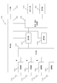
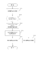
- FIG. 8 is a flowchart for explaining LDPC encoded block detection processing by the apparatus of FIG. 7.
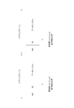
- FIG. It is a diagram for explaining the decoding start position by the decoding unit 140 1, 140 2.
- 10 is a flowchart for explaining position detection processing of the LDPC encoded block of FIG. 9.
- FIGS. In the present embodiment, a description will be given by exemplifying a receiving device that receives a terrestrial digital broadcast wave compliant with the DTMB standard.
- the same or equivalent elements are denoted by the same reference numerals, and redundant description is omitted.
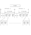
- FIG. 1 shows a frame structure defined by the DTMB standard.
- Each minute frame includes 480 super frames.
- each of the superframes includes N signal frames.
- the signal frame is the minimum unit frame for frame synchronization.
- Each signal frame is composed of a frame header (HD) and a frame body.
- the frame body is composed of 36 symbols of system information (SI) and 3744 symbols of data symbols (data symbol blocks). This system information transmits transmission parameters.
- SI system information
- data symbol blocks This system information transmits transmission parameters.
- the data symbol carries payload data that has been subjected to error correction coding.
- FIG. 2 shows the structure of a signal frame modulated by the 64QAM system
- FIG. 3 shows the structure of a signal frame modulated by the 32QAM system
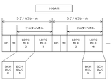
- FIG. 4 shows the configuration of a signal frame modulated by the 16QAM system
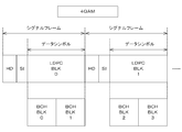
- FIG. 5 shows the configuration of a signal frame modulated by the 4QAM system
- FIG. 6 shows the configuration of a signal frame modulated by the 4QAM-NR system.
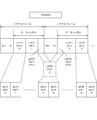
- a data symbol of one signal frame modulated by the “64QAM” scheme is encoded by a BCH code which is an outer code, and then a BCH encoded block (BCH BLK) ( It includes three LDPC coding blocks (LDPC BLK) (inner code data blocks) that are divided into outer code data blocks) and further subjected to inner coding.
- BCH BLK BCH encoded block
- LDPC BLK LDPC coding blocks
- a data symbol of one signal frame modulated by the “32QAM” method is encoded by an outer code BCH code and then divided into BCH encoded blocks. It includes 2.5 half-integer LDPC encoded blocks that have been encoded.
- the data symbol of one signal frame modulated by the “16QAM” method is encoded by the BCH code which is an outer code, and then divided into BCH encoded blocks. Two LDPC encoded blocks that have been encoded are included.
- a data symbol of one signal frame modulated by the “4QAM” method is encoded by an outer code BCH code, and then divided into BCH encoded blocks.
- One LDPC encoded block that has been encoded is included.
- a data symbol of one signal frame modulated by the “4QAM-NR” scheme is encoded by an outer code BCH code, and then divided into BCH encoded blocks.
- BCH code an outer code BCH code
- it includes 0.5 half-integer LDPC coded blocks that have been subjected to inner coding.
- the number of LDPC coding blocks in one signal frame is a half integer number, so that the start position of the data symbol is LDPC.
- a signal frame that matches the start position of the encoded block also referred to as “first type signal frame”
- a signal frame that does not match the start position of the LDPC encoded block hereinafter referred to as “second type frame”. are also transmitted alternately.
- a reception signal arranged in a vehicle will be described as an example.
- FIG. 7 shows a schematic configuration of a receiving apparatus 100 according to an embodiment.
- the receiving device 100 includes four antennas 110 1 , 110 2 , 110 3 , and 110 4 and four demodulation units 120 1 , 120 2 , 120 3 , and 120 4. Yes.
- the receiving apparatus 100 includes a synthesis unit 130, two decoding units 140 1 and 140 2, and an audio / video processing unit 150.
- the receiving device 100 includes an input unit 160, a sound output unit 170, a display unit 180, and a control unit 190.
- the antennas 110 1 , 110 2 , 110 3 and 110 4 receive digital terrestrial broadcast waves.
- the demodulator 120 j establishes signal frame synchronization, performs fast Fourier transform on the I and Q complex baseband signals for each signal frame, and generates a frequency domain signal.
- the frequency domain signal generated in this way is sent to the synthesis unit 130.
- a frequency domain signal also referred to as “signal FFD j ”
- the decoding unit 140 1 functions as a first decoding unit
- the audio / video processing unit 150 is also referred to as a decoding signal (hereinafter, “signal DMD 1 , DMD 2 ”) sent from the decoding unit 140 1 or the decoding unit 140 2 under the control of the control unit 190. ) Then, the audio / video processing unit 150 generates demodulated audio data related to audio and demodulated video data related to video based on the decoded signal. Subsequently, the audio / video processing unit 150 generates audio data based on the demodulated audio data and also generates video data based on the demodulated video data. The sound data generated in this way is sent to the sound output unit 170. Further, the video data generated in this way is sent to the display unit 180.
- a decoding signal hereinafter, “signal DMD 1 , DMD 2 ”
- the input unit 160 includes a key unit provided in the main body of the receiving device 100 and / or a remote input device including the key unit.
- a key unit provided in the main body a touch panel provided in the display device of the display unit 180 can be used. Moreover, it can replace with the structure which has a key part, or can also employ
- the user operates the input unit 160 to set the operation content of the receiving apparatus 100 and input an operation command. For example, input by the user such as channel setting setting designation is performed using the input unit 160.
- the content input to the input unit 160 is sent to the control unit 190 as operation input data.
- the sound output unit 170 includes (i) a DA (Digital-to-Analogue) converter that converts audio data sent from the audio / video processing unit 150 into an analog signal, and (ii) an output from the DA converter.
- the amplifier includes an amplifier that amplifies the analog signal, and (iii) a speaker that converts the amplified analog signal into sound.
- the sound output unit 170 reproduces and outputs broadcast sound corresponding to the broadcast wave of the selected channel.
- the display unit 180 includes, for example, (i) a display device such as a liquid crystal panel, an organic EL (Electro Luminescence) panel, a PDP (Plasma Display Panel), and (ii) video data transmitted from the audio / video processing unit 150. And a display control circuit for displaying an image on the display device.
- the display unit 180 reproduces and displays a broadcast video corresponding to the selected channel.
- the control unit 190 performs overall control of the entire receiving device 100. The control process executed by the control unit 190 will be described later.
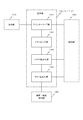
- the decoding unit 140 k includes a deinterleaving unit 141, a demapping unit 142, an LDPC decoding unit 143, and a BCH decoding unit 144.
- the deinterleaving unit 141 receives the signal sent from the synthesizing unit 130.
- the deinterleaving unit 141 detects the positions of the frame header HD, system information, and data symbols in the signal frame.
- the deinterleave unit 141 analyzes the transmission parameter and acquires the carrier modulation parameter.
- the carrier modulation parameters acquired in this way are sent to the control unit 190. That is, the deinterleave unit 141 functions as a carrier modulation scheme detection unit.
- the deinterleaving unit 141 performs OFDM (Orthogonal Frequency Division Multiplex) demodulation and frequency and time deinterleaving on the signal sent from the combining unit 130, The data is sent to the mapping unit 142.
- deinterleaving section 141 performs time deinterleaving on the signal sent from combining section 130 and sends the signal to demapping section 142.
- the demapping unit 142 receives the signal sent from the deinterleaving unit 141. Then, the demapping unit 142 calculates a determination value and noise power based on the modulated carrier amplitude and phase information. The determination value and noise power calculated by the demapping unit 142 are sent to the LDPC decoding unit 143.
- the LDPC decoding unit 143 receives the signal sent from the demapping unit 142. Then, in accordance with the decoding start position command sent from the control unit 190, the LDPC decoding unit 143 starts the decoding process from the signal frame at the position specified by the decoding start position command. In this decoding process, the LDPC decoding unit 143 performs error detection (parity check) on the LDPC code, performs error correction, and sends a signal indicating the error correction result to the BCH decoding unit 144. Further, the LDPC decoding unit 143 obtains likelihood information in the decoding process. The parity check result and the likelihood information thus obtained are sent to the control unit 190.
- error detection parity check
- the LDPC decoding unit 143 of the decoding unit 140 1 functions as a first likelihood detection unit.
- the LDPC decoding unit 143 of the decoding unit 140 2 functions as a second likelihood detection unit.
- the likelihood information is LDPC-decoded using the well-known Sum-Product algorithm, and the log likelihood ratio of the posterior probabilities of each bit output as the decoding result is used. It is not limited to.
- the log likelihood ratio is described in JP-A-2003-244109.
- the BCH decoding unit 144 receives the signal transmitted from the LDPC decoding unit 143. Then, the BCH decoding unit 144 performs error correction after performing a parity check of the BCH code, and sends the error correction result signal to the audio / video processing unit 150. Also, the BCH decoding unit 144 sends the result of the parity check to the control unit 190.
- step S ⁇ b> 11 the control unit 190 performs initial signal synthesis setting control for the synthesis unit 130.
- the control unit 190 includes a signal FFD 1 output from the demodulator 120 1, a signal SND 1 by combining the signal FFD 2 output from the demodulator 120 2
- a synthesis control command that generates and designates sending the signal to the decoding unit 140 1 is sent to the synthesis unit 130.
- the control unit 190 generates a signal FFD 3 output from the demodulator 120 3, synthesized by the signal SND 2 and a signal FFD 4 output from the demodulator 120 4 and the synthesis control instruction that specifies that sends the signal to the decoding unit 140 2 and sends it to the combining unit 130.
- the control unit 190 When the initial signal synthesis setting is performed, the control unit 190 generates a channel selection command corresponding to the channel selection setting designation and sends it to the demodulation units 120 1 to 120 4 .
- the synthesizer 130 synthesizes the two signals FFD 1 and FFD 2 , sends the signal SND 1 that is the result of the synthesis process to the decoder 140 1 , and synthesizes the two signals FFD 3 and FFD 4. Then, the signal SND 2 which is the result of the synthesis process is sent to the decoding unit 140 2 .
- step S12 the control unit 190 determines whether the carrier modulation scheme is “32QAM” or “4QAM-NR” based on the carrier modulation parameter. If the result of this determination is negative (step S12: N), that is, if the carrier modulation scheme is “64QAM”, “16QAM” or “4QAM”, the process proceeds to step S13.
- step S13 the control unit 190 performs first setting control.
- the control unit 190 combines the four signals FFD 1 to FFD 4 to generate the signal SND 1 and specifies that the signal is sent to the decoding unit 140 1 .
- a synthesis control command is sent to the synthesis unit 130.
- the control unit 190 specifies that the audio / video processing unit 150, based on the decoded signal sent from the decoding unit 140 1 generates audio data and video data Process control command to send.
- the first setting control for decoding section 140 2 issues a command to stop the process.
- the audio / video processing unit 150 When such a first setting is performed, the audio / video processing unit 150 generates audio data and video data based on the decoded signal sent from the decoding unit 140 1. The audio data and video data generated by the audio / video processing unit 150 are sent to the sound output unit 170 and the display unit 180, respectively. As a result, broadcast sound is reproduced by the sound output unit 170 and broadcast video is reproduced by the display unit 180.
- step S12 determines whether the result of the determination in step S12 described above is affirmative (step S 12: Y).
- the process proceeds to step S14.
- step S14 the control unit 190 sends against LDPC decoder 143 of the decoding unit 140 1 and the decoding unit 140 2, a decoding start position command specifying the location of the signal frame should start decoding.
- the decoding start position by the decoding unit 140 1, than the decoding start position by the decoding unit 140 2, and has a 1 signal frame delayed signal frame.
- each of the decoding units 140 1 and 140 2 performs demapping processing, LDPC decoding processing, and BCH decoding processing on the designated signal frame. . Then, each of decoding sections 140 1 and 140 2 sends LDPC code parity check results, LDPC code likelihood information, and BCH code parity check results to control section 190.
- step S ⁇ b> 15 the control unit 190 performs LDPC encoded block position detection processing. Details of the processing in step S15 will be described later.
- step S16 the control unit 190 performs second setting control.
- the determination process of step S15 if the signal frame decoding start position is specified for the decoding unit 140 1 is determined to be a first type of signal frames, control Unit 190 synthesizes the four signals FFD 1 to FFD 4 to generate signal SND 1 , and sends a synthesis control command designating that the signal is sent to decoding unit 140 1 to synthesis unit 130.
- the control unit 190, the audio / video processing unit 150, based on the decoded signal sent from the decoding unit 140 1 transmits the processing control instruction specifies that generates audio data and video data. Furthermore, in the case of the determination result, the control unit 190, to the decoder 140 2 issues a command to stop the process.
- the audio / video processing unit 150 generates audio data and video data based on the decoded signal sent from the decoding unit 140 1.
- the audio data and video data generated by the audio / video processing unit 150 are sent to the sound output unit 170 and the display unit 180, respectively.
- step S15 the determination process of step S15, the signal frame specified for the decoding unit 140 2, when it is determined that the first type of signal frames, the control unit 190 Synthesizes four signals FFD 1 to FFD 4 to generate a signal SND 2 , and sends a synthesis control command to the synthesis unit 130 to specify that the signal is sent to the decoding unit 140 2 .
- the control unit 190 transmits the decoding unit 140 2 to the audio / video processing unit 150.
- a processing control command for designating generation of audio data and video data is sent based on the decoded signal sent from.
- the control unit 190 to the decoder 140 1 issues a command to stop the process.
- the audio / video processing unit 150 generates audio data and video data based on the decoded signal sent from the decoding unit 140 2.
- the audio data and video data generated by the audio / video processing unit 150 are sent to the sound output unit 170 and the display unit 180, respectively.
- step S21 the control unit 190, the decoding unit 140 1, the result of the parity check result of the parity check LDPC encoded block and the BCH code block get.
- step S22 the control unit 190, based on the result of the parity check LDPC code and a BCH code acquired from the decoding unit 140 1, a parity check result of the decoding unit 140 1 is "OK", i.e., errors It is determined whether or not it has been detected. If the result of this determination is affirmative (step S22: Y), the control unit 190 determines that the signal frame specified for the “decoding unit 140 1 ” is the first type signal frame. To do. When the first type signal frame is thus detected, the process of step S15 ends, and the process proceeds to step S16 of FIG. 9 described above.
- step S22 determines whether or not this is detected.
- step S23 determines that the signal frame specified for the “decoding unit 140 2 ” is the first type signal frame. To do.
- the process of step S15 ends, and the process proceeds to step S16 of FIG. 9 described above.
- step S23 determines whether or not the number of processed signal frames is a predetermined number.
- the “predetermined value” is determined in advance based on experiments, simulations, experiences, and the like from the viewpoint of detecting an LDPC encoded block that can perform normal decoding processing based on likelihood information.
- step S24 If the result of the determination in step S24 is negative (step S24: N), the process proceeds to step S25.
- step S25 the control unit 190 obtains the parity check result of the LDPC code and BCH code for the next signal frame decoded by the decoding units 140 1 and 140 2 . Thereafter, the process returns to step S22.
- step S24 determines the position of the LDPC encoded block based on the comparison of the average value of the LDPC code likelihood information (hereinafter also referred to as “likelihood average”) for a predetermined number of signal frames. I do.
- the control unit 190 first calculates the likelihood average LKL 1 from the likelihood information obtained by the decoding unit 140 1 and calculates LKL 2 from the likelihood information obtained by the decoding unit 140 2. .
- the control unit 190 determines that the signal frame specified for “decoding unit 140 1 ” is the first type signal frame. Judge that there is.
- the control unit 190 determines that the signal frame specified for the “decoding unit 140 2 ” is the first type signal frame. Judge that there is.
- the process of step S15 ends, and the process proceeds to step S16 of FIG. 9 described above.
- the above process is executed each time the user inputs the channel setting setting designation to the input unit 160 as described above, and the “LDPC encoded block detection process capable of performing a normal decoding process” is performed.
- the control unit 190 when receiving a broadcast wave that is carrier-modulated by the 32QAM and 4QAM-NR schemes, the control unit 190 performs decoding on the decoding unit 140 1 and the decoding unit 140 2 .
- the position of the signal frame at which to start is shifted by one signal frame.
- Each of the decoding units 140 1 and 140 2 performs a demapping process, an LDPC decoding process, and a BCH decoding process on the designated signal frame.
- the parity check of the BCH code is performed. The result is sent to the control unit 190.
- the control unit 190 indicates that the signal frame designated for the “decoding unit 140 1 ” has an LDPC encoded block whose data symbol start position is It is determined that the signal frame coincides with the start position.
- the control unit 190 indicates that the signal frame designated for the “decoding unit 140 2 ” has a data symbol start position of the LDPC coding block. It is determined that the signal frame coincides with the start position.
- a signal conforming to the DTMB standard can be received and appropriate signal processing can be performed.
- a signal frame in which the start position of the data symbol matches the start position of the LDPC encoded block cannot be detected based on the result of the parity check of the LDPC code and the BCH code, decoding is performed. Based on the likelihood information obtained by unit 140 1 and the likelihood information obtained by decoding unit 140 2, a signal frame in which the start position of the data symbol matches the start position of the LDPC encoded block is detected.
- the receiving apparatus of the above embodiment includes four sets of antennas and demodulation units, but the number of sets of antennas and demodulation units may be 1 to 3, or 5 or more sets. Good.
- the demodulation result by one demodulating unit may be sent to each of the decoding units 140 1 and 140 2 .
- the combining unit can be omitted.
- a signal frame in which the start position of the data symbol coincides with the start position of the LDPC encoded block is detected based on the result of the parity check of the LDPC code and the BCH code. If there is a clear difference between the parity checks (error detection results) of the BCH code, the signal in which the start position of the data symbol matches the start position of the LDPC coding block is given priority over the parity check comparison result of the BCH code. A frame may be detected.
- the present invention is applied to a receiving device mounted on a vehicle.
- the present invention can also be applied to a receiving device arranged on a moving body other than a vehicle, or a smartphone.
- the present invention can also be applied to a receiving device arranged in a portable terminal device. Further, for example, the present invention can be applied to a receiving device installed in a home or the like.
- control unit is configured as a computer as a calculation unit including a central processing unit (CPU: Central Processing ⁇ Unit) and the like, by executing a program prepared in advance on the computer, You may make it implement
- This program is recorded on a computer-readable recording medium such as a hard disk, CD-ROM, or DVD, and is read from the recording medium and executed by the computer.
- the program may be acquired in a form recorded on a portable recording medium such as a CD-ROM or DVD, or may be acquired in a form distributed via a network such as the Internet. Also good.
Landscapes
- Physics & Mathematics (AREA)
- Probability & Statistics with Applications (AREA)
- Engineering & Computer Science (AREA)
- Theoretical Computer Science (AREA)
- Two-Way Televisions, Distribution Of Moving Picture Or The Like (AREA)
Abstract
制御部(190)は、復号部(1401,1402)に対して、復号を開始すべきシグナルフレームの位置を1シグナルフレーム分ずらして指定する。復号部(1401,1402)のそれぞれは、指定されたシグナルフレームに対してLDPC符号及びBCH符号のパリティチェックを行う。そして、制御部(190)は、パリティチェック結果が正常であった復号部に対して指定したシグナルフレームが、データシンボルの開始位置がLDPC符号化ブロックの開始位置と一致するシグナルフレームであると判定する。また、制御部(190)は、受信信号の品質が悪く、復号部(1401,1402)の双方のパリティチェック結果が正常でない場合は、LDPC復号処理で用いる尤度情報から、LDPC符号化ブロックの開始位置と一致するシグナルフレームを判定する。
Description
本発明は、受信装置、受信処理方法、受信処理プログラム、及び、当該受信処理プログラムが記録された記録媒体に関する。
近年、地上デジタル放送が、世界各国で急速に普及している。こうした地上デジタル放送に関する規格は複数あるが、中国においては、DTMB(Digital Terrestrial Multimedia Broadcast)規格が採用されている。このDTMB規格は、マルチキャリア伝送方式と、シングルキャリア伝送方式とを混在させたものであり、中国独自の規格となっている。
かかるDTMB規格は、キャリア変調方式として、64QAM(Quadrature Amplitude Moduration),32QAM,16QAM,4QAM,4QAM-NRを採用している。これらのキャリア変調方式のうち、64QAM,16QAM,4QAMについては、1シグナルフレーム中のLDPC(Low-Density Parity-Check)符号化ブロックの数は整数となっているが、32QAM及び4QAM-NRについては、1シグナルフレーム中のLDPC符号化ブロックの数が、半整数となっている。このため、32QAM及び4QAM-NRのキャリア変調方式では、1つのLDPC符号化ブロックが2つのシグナルフレームにまたがることがある。
こうしたDTMB規格に準拠した放送波を受信するためには、32QAM及び4QAM-NRの方式でキャリア変調された放送波を受信したときに、正常な復号処理を行えるLDPC符号化ブロックの位置を検出する必要がある。こうした必要性から、正常な復号処理を行えるLDPC符号化ブロックの位置を検出するための技術が提案されている(特許文献1参照:以下、「従来例」という)。
この従来例の技術では、1つの復号部を備え、受信した放送波に対して内符号であるLDPC符号の復号処理、外符号であるBCH符号の復号処理、及び、BCH復号のパリティチェックで誤りが検出されたか否かの判定処理を行う。引き続き、BCH復号のパリティチェックで誤りが検出された場合には、LDPC符号化ブロックの位置を変更して、BCH復号のパリティチェックで誤りが検出されなくなるまで、LDPC符号の復号処理、BCH符号の復号処理、及び、BCH復号のパリティチェックの判定処理を行うようになっている。そして、BCH復号のパリティチェックで誤りが検出されないときのLDPC符号化ブロックの位置が、正常な復号処理を行えるLDPC符号化ブロックの位置であると判定する。
上述した従来例の技術では、正常な復号処理を行えるLDPC符号化ブロックの位置が検出されるまで、LDPC符号の復号処理、BCH符号の復号処理、及び、BCH復号のパリティチェックの判定処理を、繰り返し行う。このため、パリティチェックの再判定処理を行うたびにLDPC符号化ブロックの位置を変更するなどの処理が必要となり、制御が複雑化する。また、従来例の技術では、パリティチェックの再判定処理を行った場合には、音声や映像の再生出力までに、少なくても1シグナルフレーム分の待ち時間が発生する。
このため、DTMB規格に従った1シグナルフレーム中のLDPC符号化ブロックの数が半整数となるキャリア変調信号を受信した際に、迅速に、正常な復号処理を行えるLDPC符号化ブロックの位置を検出することができる技術が望まれている。かかる要請に応えることが、本発明が解決すべき課題の一つとして挙げられる。
本発明は、上記の事情を鑑みてなされたものであり、DTMB規格に従った信号を受信し、適切な信号処理を行うことができる新たな受信装置及び受信処理方法を提供することを目的とする。
本発明は、第1の観点からすると、フレーム同期の最小単位としてのシグナルフレームであり、外符号化が行われた外符号データブロックを複数個含み、内符号化が行われた内符号データブロックを半整数個含むシグナルフレームとして、データシンボルブロックの開始位置が前記内符号データブロックの開始位置と一致する第1種のシグナルフレームと、前記データシンボルブロックの開始位置が前記内符号データブロックの開始位置と一致しない第2種のシグナルフレームとを交互に受信する可能性がある情報を担った伝送信号を受信する受信装置であって、復号処理を開始した前記シグナルフレームにおけるデータシンボルブロックの開始位置が前記内符号ブロックの開始位置であるとして、前記内符号データブロックの復号の後に前記外符号データブロックの復号を行う第1復号部及び第2復号部と;前記第1復号部及び前記第2復号部に対して、前記復号を開始すべきシグナルフレームの位置を、1シグナルフレーム分ずらして指定するとともに、前記第1復号部及び前記第2復号部のそれぞれの復号結果における誤り検出結果に基づいて、前記第1種のシグナルフレームから前記復号を開始した復号部の識別の処理を行う制御部と;を備えることを特徴とする受信装置である。
本発明は、第2の観点からすると、フレーム同期の最小単位としてのシグナルフレームであり、外符号化が行われた外符号データブロックを複数個含み、内符号化が行われた内符号データブロックを半整数個含むシグナルフレームとして、データシンボルブロックの開始位置が前記内符号データブロックの開始位置と一致する第1種のシグナルフレームと、前記データシンボルブロックの開始位置が前記内符号データブロックの開始位置と一致しない第2種のシグナルフレームとを交互に受信する可能性がある情報を担った伝送信号を受信する受信装置において使用される受信処理方法であって、前記内符号データブロックの復号の後に前記外符号データブロックの復号を行う第1復号部及び第2復号部に対して、前記復号を開始すべきシグナルフレームの位置を、1シグナルフレーム分ずらして指定する指定工程と;前記第1復号部及び前記第2復号部のそれぞれの復号結果における誤り検出結果に基づいて、前記第1種のシグナルフレームから前記復号を開始した復号部の識別の処理を行う識別処理工程と;を備えることを特徴とする受信処理方法である。
本発明は、第3の観点からすると、本発明の受信処理方法を演算部に実行させる、ことを特徴とする受信処理プログラムである。
本発明は、第4の観点からすると、本発明の受信処理プログラムが、演算部により読み取り可能に記録されている、ことを特徴とする記録媒体である。
100 … 受信装置
1401 … 復号部(第1復号部)
1402 … 復号部(第2復号部)
141 … デインターリーブ部(キャリア変調方式検出部)
143 … LDPC復号化部(第1尤度検出部、第2尤度検出部)
190 … 制御部
1401 … 復号部(第1復号部)
1402 … 復号部(第2復号部)
141 … デインターリーブ部(キャリア変調方式検出部)
143 … LDPC復号化部(第1尤度検出部、第2尤度検出部)
190 … 制御部
以下、本発明の一実施形態を、図1~図11を参照して説明する。本実施形態では、DTMB規格に準拠した地上デジタル放送波を受信する受信装置を例示して、説明を行う。なお、以下の説明及び図面においては、同一又は同等の要素には同一の符号を付し、重複する説明を省略する。
[受信信号のフレーム構造]
本実施形態に係る受信装置の構成の説明に先立って、DTMB規格におけるフレームの構造について説明する。図1には、DTMB規格で規定されるフレーム構造が示されている。
本実施形態に係る受信装置の構成の説明に先立って、DTMB規格におけるフレームの構造について説明する。図1には、DTMB規格で規定されるフレーム構造が示されている。
図1に示されるように、DTMB規格で規定されるフレーム構造では、1日分のフレームであるデイフレームには、1440(=24×60)個のミニッツフレームが含まれている。そして、ミニッツフレームのそれぞれには、480個のスーパーフレームが含まれている。さらに、スーパーフレームのそれぞれには、N個のシグナルフレームが含まれている。
シグナルフレームは、フレーム同期の最小単位のフレームである。このシグナルフレームのそれぞれは、フレームヘッダ(HD)とフレームボディとから構成される。そして、フレームボディは、36シンボルのシステムインフォメーション(SI)と、3744シンボルのデータシンボル(データシンボルブロック)から構成される。このシステムインフォメーションは、伝送パラメータを伝送する。また、データシンボルは、誤り訂正符号化されたペイロードデータを伝送する。
図2には、64QAM方式で変調されたシグナルフレームの構成が示され、図3には、32QAM方式で変調されたシグナルフレームの構成が示されている。また、図4には、16QAM方式で変調されたシグナルフレームの構成が示され、図5には、4QAM方式で変調されたシグナルフレームの構成が示されている。さらに、図6には、4QAM-NR方式で変調されたシグナルフレームの構成が示されている。
ここで、「64QAM」方式で変調された1つのシグナルフレームのデータシンボルは、図2に示されるように、外符号であるBCH符号により符号化された後に、BCH符号化ブロック(BCH BLK)(外符号データブロック)に分割され、さらに内符号化が行われたLDPC符号化ブロック(LDPC BLK)(内符号データブロック)を3個含んでいる。また、「32QAM」方式で変調された1つのシグナルフレームのデータシンボルは、図3に示されるように、外符号であるBCH符号により符号化された後に、BCH符号化ブロックに分割され、さらに内符号化が行われたLDPC符号化ブロックを半整数個である2.5個含んでいる。
また、「16QAM」方式で変調された1つのシグナルフレームのデータシンボルは、図4に示されるように、外符号であるBCH符号により符号化された後に、BCH符号化ブロックに分割され、さらに内符号化が行われたLDPC符号化ブロックを2個含んでいる。また、「4QAM」方式で変調された1つのシグナルフレームのデータシンボルは、図5に示されるように、外符号であるBCH符号により符号化された後に、BCH符号化ブロックに分割され、さらに内符号化が行われたLDPC符号化ブロックを1個含んでいる。
さらに、「4QAM-NR」方式で変調された1つのシグナルフレームのデータシンボルは、図6に示されるように、外符号であるBCH符号により符号化された後に、BCH符号化ブロックに分割され、さらに内符号化が行われたLDPC符号化ブロックを半整数個である0.5個含んでいる。
このように、「32QAM」方式及び「4QAM-NR」方式で変調されたシグナルフレームでは、1つのシグナルフレーム中のLDPC符号化ブロックの数が半整数個であるため、データシンボルの開始位置がLDPC符号化ブロックの開始位置と一致するシグナルフレーム(「第1種のシグナルフレーム」とも記す)と、データシンボルの開始位置がLDPC符号化ブロックの開始位置と一致しないシグナルフレーム(以下、「第2種のシグナルフレーム」とも記す)とが、交互に伝送される。
このため、第1種のシグナルフレームをLDPC復号の開始位置とした場合には、正常な復号処理を行うことができ、第2種のシグナルフレームをLDPC復号の開始位置とした場合には、正常な復号処理を行うことができない。
[受信装置の構成]
次に、本実施形態に係る受信装置100の構成について説明する。なお、本実施形態では、車両に配置された受信信号を例示して説明する。
図7には、一実施形態に係る受信装置100の概略的な構成が示されている。図7に示されるように、受信装置100は、4個のアンテナ1101,1102,1103,1104と、4個の復調部1201,1202,1203,1204とを備えている。また、受信装置100は、合成部130と、2個の復号部1401,1402と、音声/映像処理部150とを備えている。さらに、受信装置100は、入力部160と、音出力部170と、表示部180と、制御部190とを備えている。
上記のアンテナ1101,1102,1103,1104は、地上デジタル放送波を受信する。アンテナ110j(j=1,…,4)による受信信号(RF信号)は、復調部120jへ送られる。
上記の復調部120j(j=1,…,4)のそれぞれは、4個のアンテナ110jごとに配置され、アンテナ110jから送られた受信信号(RF信号)を受ける。そして、復調部120jは、制御部190から送られた選局指令に従って、選択すべき物理チャンネルの信号を受信信号から抽出する選局処理を行う。引き続き、復調部120jは、当該抽出された信号(IF信号)をデジタル形式の信号に変換し、当該デジタル形式に変換された信号に基づいて、互いに直交するI,Q複素ベースバンド信号を生成する。
復調部120jは、シグナルフレーム同期を確立し、シグナルフレーム毎のI,Q複素ベースバンド信号に対して高速フーリエ変換を行い、周波数領域信号を生成する。こうして生成された周波数領域信号は、合成部130へ送られる。
上記の合成部130は、復調部120j(j=1,…,4)のそれぞれから送られた周波数領域信号(「信号FFDj」とも記す)を受ける。そして、合成部130は、制御部190による制御のもとで、信号合成処理を行う。引き続き、合成部130は、合成された信号を、復号部1401,1402へ送る。合成部130による信号合成処理の詳細については、後述する。
上記の復号部1401,1402のそれぞれは、合成部130から送られた信号(「信号SND1,SND2」とも記す)を受ける。そして、復号部140k(k=1,2)は、制御部190による制御のもとで、合成部130から送られた信号の復号処理を行い、復号処理結果である復号信号を、音声/映像処理部150へ送る。ここで、復号部1401が、第1復号部としての機能を果たし、復号部1402が、第2復号部としての機能を果たすようになっている。復号部140k(k=1,2)の詳細な構成については、後述する。
上記の音声/映像処理部150は、制御部190による制御のもとで、復号部1401、又は、復号部1402から送られた復号信号(以下、「信号DMD1,DMD2」とも記す)を受ける。そして、音声/映像処理部150は、復号信号に基づいて、音声に関する復調音声データ、及び、映像に関する復調映像データを生成する。引き続き、音声/映像処理部150は、復調音声データに基づいて音声データを生成するとともに、復調映像データに基づいて映像データを生成する。こうして生成された音声データは、音出力部170へ送られる。また、こうして生成された映像データは、表示部180へ送られる。
上記の入力部160は、受信装置100の本体部に設けられたキー部、及び/又はキー部を備えるリモート入力装置等により構成される。ここで、本体部に設けられたキー部としては、表示部180の表示デバイスに設けられたタッチパネルを用いることができる。また、キー部を有する構成に代えて、又は併用して音声認識技術を利用して音声にて入力する構成を採用することもできる。
この入力部160を利用者が操作することにより、受信装置100の動作内容の設定や動作指令の入力が行われる。例えば、選局設定指定等の利用者による入力が、入力部160を利用して行われる。入力部160への入力内容は、操作入力データとして、制御部190へ送られる。
上記の音出力部170は、(i)音声/映像処理部150から送られた音声データをアナログ信号に変換するDA(Digital to Analogue)変換器と、(ii)当該DA変換器から出力されたアナログ信号を増幅する増幅器と、(iii)増幅されたアナログ信号を音声に変換するスピーカとを備えて構成されている。この音出力部170は、選局されているチャンネルの放送波に対応する放送音声を再生出力する。
上記の表示部180は、例えば、(i)液晶パネル、有機EL(Electro Luminescence)パネル、PDP(Plasma Display Panel)等の表示デバイスと、(ii)音声/映像処理部150から送られた映像データに基づいて、当該表示デバイスに画像を表示させる表示制御回路とを備えている。この表示部180は、選局されているチャンネルに対応する放送映像を再生表示する。
上記の制御部190は、受信装置100の全体を統括制御する。この制御部190が実行する制御処理については、後述する。
<復号部140kの構成>
次に、上述した復号部140k(k=1,2)の構成について説明する。復号部140kは、図8に示されるように、デインターリーブ部141と、デマッピング部142と、LDPC復号化部143と、BCH復号化部144とを備えている。
次に、上述した復号部140k(k=1,2)の構成について説明する。復号部140kは、図8に示されるように、デインターリーブ部141と、デマッピング部142と、LDPC復号化部143と、BCH復号化部144とを備えている。
上記のデインターリーブ部141は、合成部130から送られた信号を受ける。そして、デインターリーブ部141は、シグナルフレームにおけるフレームヘッダHD、システムインフォメーション、データシンボルの位置を検出する。また、デインターリーブ部141は、システムインフォメーションの位置の検出後に、伝送パラメータを解析して、キャリア変調パラメータを取得する。こうして取得されたキャリア変調パラメータは、制御部190へ送られる。すなわち、デインターリーブ部141は、キャリア変調方式検出部としての機能を果たすようになっている。
また、デインターリーブ部141は、伝送方式がマルチキャリアの場合は、合成部130から送られた信号に対して、OFDM(Orthogonal Frequency Division Multiplex)復調、並びに、周波数及び時間のデインターリーブを施し、デマッピング部142へ送る。また、デインターリーブ部141は、伝送方式がシングルキャリアの場合は、合成部130から送られた信号に対して、時間のデインターリーブを施し、デマッピング部142へ送る。
上記のデマッピング部142は、デインターリーブ部141から送られた信号を受ける。そして、デマッピング部142は、変調されたキャリアの振幅及び位相情報に基づいて、判定値および雑音電力を算出する。デマッピング部142で算出された判定値および雑音電力は、LDPC復号化部143へ送られる。
上記のLDPC復号化部143は、デマッピング部142から送られた信号を受ける。そして、LDPC復号化部143は、制御部190から送られた復号開始位置指令に従って、当該復号開始位置指令により指定された位置のシグナルフレームから、復号処理を開始する。かかる復号処理に際して、LDPC復号化部143は、LDPC符号の誤り検出(パリティチェック)を行ったうえで誤り訂正を行い、誤り訂正結果の信号をBCH復号化部144へ送る。また、LDPC復号化部143は、復号処理に際して、尤度情報を求める。こうして求められたパリティチェックの結果、及び、尤度情報は、制御部190へ送られる。
すなわち、復号部1401のLDPC復号化部143は、第1尤度検出部としての機能を果たすようになっている。また、復号部1402のLDPC復号化部143は、第2尤度検出部としての機能を果たすようになっている。
本実施形態では、尤度情報は、周知のSum-Productアルゴリズムを用いてLDPC復号し、復号結果として出力される各ビットの事後確率の対数尤度比としているが、尤度情報としては、これに限られるものではない。なお、対数尤度比については、特開2003-244109号公報等に記載されている。
上記のBCH復号化部144は、LDPC復号化部143から送られた信号を受ける。そして、BCH復号化部144は、BCH符号のパリティチェックを行ったうえで誤り訂正を行い、誤り訂正結果の信号を音声/映像処理部150へ送る。また、BCH復号化部144は、パリティチェックの結果を制御部190へ送る。
<動作>
以上のようにして構成された受信装置100の動作について、制御部190による「正常な復号処理を行えるLDPC符号化ブロックの検出処理」に主に着目して説明する。
以上のようにして構成された受信装置100の動作について、制御部190による「正常な復号処理を行えるLDPC符号化ブロックの検出処理」に主に着目して説明する。
かかる検出処理は、利用者による選局設定指定の入力部160への入力に対応して開始される。こうして受信処理が開始されると、図9に示されるように、まず、ステップS11において、制御部190が、合成部130に対して初期信号合成の設定制御を行う。このステップS11における初期信号合成の設定制御では、制御部190は、復調部1201から出力される信号FFD1と、復調部1202から出力される信号FFD2とを合成して信号SND1を生成し、当該信号を復号部1401へ送ることを指定する合成制御指令を、合成部130へ送る。また、かかる初期信号合成の設定制御では、制御部190は、復調部1203から出力される信号FFD3と、復調部1204から出力される信号FFD4とを合成して信号SND2を生成し、当該信号を復号部1402へ送ることを指定する合成制御指令を、合成部130へ送る。
初期信号合成の設定が行われると、制御部190が、選局設定指定に対応する選局指令を生成し、復調部1201~1204へ送る。選局指令を受けた復調部120j(j=1~4)では、受信信号の選局処理、シグナルフレーム同期処理、及び、復調処理が行われ、復調処理結果である信号FFDjが合成部130へ送られる。合成部130では、信号FFD1,FFD2の2つの信号の合成を行い、合成処理結果である信号SND1を復号部1401へ送るとともに、信号FFD3,FFD4の2つの信号の合成を行い、合成処理結果である信号SND2を復号部1402へ送る。
復号部140k(k=1,2)では、信号SND kを受けると、システムインフォメーションに基づいて伝送パラメータを解析し、キャリア変調パラメータを制御部190へ送る。
こうした状況のもとで、ステップS12において、制御部190が、キャリア変調パラメータに基づいて、キャリア変調方式が、「32QAM」又は「4QAM-NR」であるか否かを判定する。この判定の結果が否定的であった場合(ステップS12:N)、すなわち、キャリア変調方式が、「64QAM」、「16QAM」又は「4QAM」の場合は、ステップS13へ進む。
ステップS13では、制御部190が、第1の設定制御を行う。このステップS13における第1の設定制御では、制御部190は、信号FFD1~FFD4の4つの信号を合成して信号SND1を生成し、当該信号を復号部1401へ送ることを指定する合成制御指令を、合成部130へ送る。また、かかる第1の設定制御では、制御部190は、音声/映像処理部150に対して、復号部1401から送られた復号信号に基づいて、音声データ及び映像データを生成することを指定する処理制御指令を送る。また、第1の設定制御では、復号部1402に対して、処理を停止させる指令を発行する。そして、ステップS13の設定制御が終了すると、制御部190による「正常な復号処理を行えるLDPC符号化ブロックの検出処理」が終了する。
こうした第1の設定が行われると、音声/映像処理部150は、復号部1401から送られた復号信号に基づいて音声データ及び映像データを生成する。そして、音声/映像処理部150により生成された音声データ及び映像データは、それぞれ、音出力部170及び表示部180へ送られる。この結果、放送音声が音出力部170により再生されるとともに、放送映像が表示部180により再生される。
一方、上述したステップS12における判定の結果が肯定的であった場合(ステップS
12:Y)には、処理はステップS14へ進む。ステップS14では、制御部190が、復号部1401及び復号部1402のLDPC復号化部143に対して、復号を開始すべきシグナルフレームの位置を指定した復号開始位置指令を送る。本実施形態では、図10に示されるように、復号部1401による復号開始位置が、復号部1402による復号開始位置よりも、1シグナルフレーム分遅れたシグナルフレームとなっている。
12:Y)には、処理はステップS14へ進む。ステップS14では、制御部190が、復号部1401及び復号部1402のLDPC復号化部143に対して、復号を開始すべきシグナルフレームの位置を指定した復号開始位置指令を送る。本実施形態では、図10に示されるように、復号部1401による復号開始位置が、復号部1402による復号開始位置よりも、1シグナルフレーム分遅れたシグナルフレームとなっている。
こうして制御部190により復号開始位置の指定が行われると、復号部1401,1402のそれぞれは、指定されたシグナルフレームに対して、デマッピング処理、LDPC復号化処理、BCH復号化処理を行う。そして、復号部1401,1402のそれぞれは、LDPC符号のパリティチェックの結果、LDPC符号の尤度情報、BCH符号のパリティチェックの結果を制御部190へ送る。
図9に戻り、引き続き、ステップS15において、制御部190が、LDPC符号化ブロックの位置検出処理を行う。かかるステップS15の処理の詳細については、後述する。
次いで、ステップS16において、制御部190が、第2の設定制御を行う。この第2の設定制御では、ステップS15の判定処理により、復号部1401に対して復号開始位置が指定されたシグナルフレームが、第1種のシグナルフレームであると判定された場合には、制御部190は、信号FFD1~FFD4の4つの信号を合成して信号SND1を生成し、当該信号を復号部1401へ送ることを指定する合成制御指令を、合成部130へ送る。また、復号部1401に対して復号開始位置が指定されたシグナルフレームが第1種のシグナルフレームであると判定された場合には、制御部190は、音声/映像処理部150に対して、復号部1401から送られた復号信号に基づいて、音声データ及び映像データを生成することを指定する処理制御指令を送る。さらに、当該判定結果の場合には、制御部190は、復号部1402に対して、処理を停止させる指令を発行する。
この結果、音声/映像処理部150は、復号部1401から送られた復号信号に基づいて音声データ及び映像データを生成する。そして、音声/映像処理部150により生成された音声データ及び映像データは、それぞれ、音出力部170及び表示部180へ送られる。
また、この第2の設定制御では、ステップS15の判定処理により、復号部1402に対して指定されたシグナルフレームが、第1種のシグナルフレームであると判定された場合には、制御部190は、信号FFD1~FFD4の4つの信号を合成して信号SND2を生成し、当該信号を復号部1402へ送ることを指定する合成制御指令を、合成部130へ送る。また、復号部1402に対して指定されたシグナルフレームが第1種のシグナルフレームであると判定された場合には、制御部190は、音声/映像処理部150に対して、復号部1402から送られた復号信号に基づいて、音声データ及び映像データを生成することを指定する処理制御指令を送る。さらに、当該判定結果の場合には、制御部190は、復号部1401に対して、処理を停止させる指令を発行する。
この結果、音声/映像処理部150は、復号部1402から送られた復号信号に基づいて音声データ及び映像データを生成する。そして、音声/映像処理部150により生成された音声データ及び映像データは、それぞれ、音出力部170及び表示部180へ送られる。
<LDPC符号化ブロックの位置検出処理>
次に、上述したステップS15における「LDPC符号化ブロックの位置検出処理」について説明する。
次に、上述したステップS15における「LDPC符号化ブロックの位置検出処理」について説明する。
かかるステップS15における処理は、図11に示されるように、ステップS21において、制御部190が、復号部1401から、LDPC符号化ブロックのパリティチェックの結果及びBCH符号化ブロックのパリティチェックの結果を取得する。また、制御部190は、復号部1402から、LDPC符号化ブロックのパリティチェックの結果及びBCH符号化ブロックのパリティチェックの結果を取得する。
引き続き、ステップS22において、制御部190が、復号部1401から取得したLDPC符号及びBCH符号のパリティチェックの結果に基づいて、復号部1401のパリティチェックの結果が「OK」、すなわち、誤りが存在しないことを検出したか否かを判定する。この判定の結果が肯定的であった場合(ステップS22:Y)には、制御部190は、「復号部1401」に対して指定したシグナルフレームが、第1種のシグナルフレームであると判定する。こうして第1種のシグナルフレームが検出されると、ステップS15の処理が終了し、処理は、上述した図9のステップS16へ進む。
一方、ステップS22における判定の結果が否定的であった場合(ステップS22:N)には、処理はステップS23へ進む。ステップS23では、制御部190が、復号部1402から取得したLDPC符号及びBCH符号のパリティチェックの結果に基づいて、復号部1402のパリティチェックの結果が「OK」、すなわち、誤りが存在しないことを検出したか否かを判定する。この判定の結果が肯定的であった場合(ステップS23:Y)には、制御部190は、「復号部1402」に対して指定したシグナルフレームが、第1種のシグナルフレームであると判定する。こうして第1種のシグナルフレームが検出されると、ステップS15の処理が終了し、処理は、上述した図9のステップS16へ進む。
一方、ステップS23における判定の結果が否定的であった場合(ステップS23:N)には、処理はステップS24へ進む。ステップS24では、制御部190が、処理したシグナルフレームの数が所定数であるか否かを判定する。ここで、「所定値」は、尤度情報に基づいて、正常な復号処理を行えるLDPC符号化ブロックの検出する観点から、実験、シミュレーション、経験等に基づいて、予め定められる。
このステップS24における判定の結果が否定的であった場合(ステップS24:N)には、処理はステップS25へ進む。このステップS25では、制御部190が、復号部1401,1402が復号処理した次のシグナルフレームについてのLDPC符号及びBCH符号のパリティチェックの結果を取得する。この後、処理はステップS22へ戻る。
一方、上述したステップS24における判定の結果が肯定的であった場合(ステップS24:Y)には、処理はステップS26へ進む。ステップS26では、制御部190が、所定数のシグナルフレームについてのLDPC符号の尤度情報の平均値(以下、「尤度平均」とも記す)の比較に基づいて、LDPC符号化ブロックの位置の判定を行う。
かかる判定に際して、制御部190は、まず、復号部1401により求められた尤度情報から尤度平均LKL1を算出するとともに、復号部1402により求められた尤度情報からLKL2を算出する。そして、制御部190は、尤度平均LKL1≧尤度平均LKL2の関係が成立する場合には、「復号部1401」に対して指定されたシグナルフレームが、第1種のシグナルフレームであると判定する。一方、制御部190は、尤度平均LKL1<尤度平均LKL2の関係が成立する場合には、「復号部1402」に対して指定されたシグナルフレームが、第1種のシグナルフレームであると判定する。こうして第1種のシグナルフレームが検出されると、ステップS15の処理が終了し、処理は、上述した図9のステップS16へ進む。
上記のようにして利用者による選局設定指定の入力部160への入力が行われるごとに上記の処理が実行され、「正常な復号処理を行えるLDPC符号化ブロックの検出処理」が行われる。
以上説明したように、本実施形態では、32QAM及び4QAM-NRの方式でキャリア変調された放送波を受信したときに、制御部190が、復号部1401及び復号部1402に対して、復号を開始すべきシグナルフレームの位置を、1シグナルフレーム分ずらして指定する。復号部1401,1402のそれぞれは、指定されたシグナルフレームに対して、デマッピング処理、LDPC復号化処理、BCH復号化処理を行い、LDPC符号のパリティチェックの結果、BCH符号のパリティチェックの結果を制御部190へ送る。そして、制御部190は、復号部1401のパリティチェックの結果が「OK」の場合には、「復号部1401」に対して指定したシグナルフレームが、データシンボルの開始位置がLDPC符号化ブロックの開始位置と一致するシグナルフレームであると判定する。また、制御部190は、復号部1402のパリティチェックの結果が「OK」の場合には、「復号部1402」に対して指定したシグナルフレームが、データシンボルの開始位置がLDPC符号化ブロックの開始位置と一致するシグナルフレームであると判定する。
したがって、本実施形態によれば、DTMB規格に従った信号を受信し、適切な信号処理を行うことができる。
また、本実施形態では、LDPC符号及びBCH符号のパリティチェックの結果に基づいて、データシンボルの開始位置がLDPC符号化ブロックの開始位置と一致するシグナルフレームを検出することができない場合には、復号部1401により求められた尤度情報、及び、復号部1402により求められた尤度情報に基づいて、データシンボルの開始位置がLDPC符号化ブロックの開始位置と一致するシグナルフレームを検出する。
このため、車両等の移動体の移動に伴う移動受信等により、パリティチェックで誤りが持続的に発生する環境下においても、正常な復号処理を行えるLDPC符号化ブロックの位置を検出することができる。
[実施形態の変形]
本発明は、上記の実施形態に限定されるものではなく、様々な変形が可能である。
本発明は、上記の実施形態に限定されるものではなく、様々な変形が可能である。
例えば、上記の実施形態の受信装置は、アンテナ及び復調部を4組備えることとしたが、アンテナ及び復調部の組は、1~3組であってもよいし、5組以上であってもよい。なお、アンテナ及び復調部の組を1組とする場合には、1つの復調部による復調結果を、復号部1401,1402のそれぞれへ送るようにすればよい。そして、このときには合成部を省略することができる。
また、上記の実施形態では、LDPC符号及びBCH符号のパリティチェックの結果に基づいて、データシンボルの開始位置がLDPC符号化ブロックの開始位置と一致するシグナルフレームを検出するようにしたが、BCH符号のパリティチェック(誤り検出結果)の間に明らかな差がある場合には、BCH符号のパリティチェックの比較結果を優先して、データシンボルの開始位置がLDPC符号化ブロックの開始位置と一致するシグナルフレームを検出するようにしてもよい。
また、上記の実施形態では、LDPC符号及びBCH符号のパリティチェックの結果に基づいて、データシンボルの開始位置がLDPC符号化ブロックの開始位置と一致するシグナルフレームを検出することができない場合には、復号部1401により求められた尤度情報、及び、復号部1402により求められた尤度情報に基づいて、データシンボルの開始位置がLDPC符号化ブロックの開始位置と一致するシグナルフレームを検出することとしたが、尤度情報に基づく判定処理を省略するようにしてもよい。
また、上記の実施形態においては、車両に搭載される受信装置に本発明を適用したが、車両以外の他の移動体に配置される受信装置にも本発明を適用することもできるし、スマートフォン等の携帯端末装置に配置される受信装置にも本発明を適用することができる。また、例えば、家庭内等に設置される受信装置に本発明を適用することもできる。
なお、上記の制御部の一部又は全部を中央処理装置(CPU:Central Processing Unit)等を備えた演算手段としてのコンピュータとして構成し、予め用意されたプログラムを当該コンピュータで実行することにより、上記の実施形態における制御部の機能を実現するようにしてもよい。このプログラムはハードディスク、CD-ROM、DVD等のコンピュータで読み取り可能な記録媒体に記録され、当該コンピュータによって記録媒体から読み出されて実行される。また、このプログラムは、CD-ROM、DVD等の可搬型記録媒体に記録された形態で取得されるようにしてもよいし、インターネットなどのネットワークを介した配信の形態で取得されるようにしてもよい。
Claims (9)
- フレーム同期の最小単位としてのシグナルフレームであり、外符号化が行われた外符号データブロックを複数個含み、内符号化が行われた内符号データブロックを半整数個含むシグナルフレームとして、データシンボルブロックの開始位置が前記内符号データブロックの開始位置と一致する第1種のシグナルフレームと、前記データシンボルブロックの開始位置が前記内符号データブロックの開始位置と一致しない第2種のシグナルフレームとを交互に受信する可能性がある情報を担った伝送信号を受信する受信装置であって、
復号処理を開始した前記シグナルフレームにおけるデータシンボルブロックの開始位置が前記内符号ブロックの開始位置であるとして、前記内符号データブロックの復号の後に前記外符号データブロックの復号を行う第1復号部及び第2復号部と;
前記第1復号部及び前記第2復号部に対して、前記復号を開始すべきシグナルフレームの位置を、1シグナルフレーム分ずらして指定するとともに、前記第1復号部及び前記第2復号部のそれぞれの復号結果における誤り検出結果に基づいて、前記第1種のシグナルフレームから前記復号を開始した復号部の識別の処理を行う制御部と;
を備えることを特徴とする受信装置。 - 前記制御部は、前記外符号データブロックにおける誤り検出結果の間に明らかな差がある場合には、前記外符号データブロックにおける誤り検出結果の比較結果を優先して、前記識別の処理を行う、ことを特徴とする請求項1に記載の受信装置。
- 前記第1復号部は、前記内符号データブロックの復号結果の尤度を検出する第1尤度検出部を備え、
前記第2復号部は、前記内符号データブロックの復号結果の尤度を検出する第2尤度検出部を備え、
前記制御部は、前記内符号データブロック及び前記外符号データブロックに関する誤り検出結果の比較では前記識別を行うことができない場合には、前記第1尤度検出部及び前記第2尤度検出部による検出結果の識別結果に基づいて、前記識別を行う、
ことを特徴とする請求項1に記載の受信装置。 - 前記第1種のシグナルフレーム及び前記第2種のシグナルフレームを含むか否かは、前記伝送信号のキャリア変調方式により定まり、
前記伝送信号のキャリア変調方式を検出するキャリア変調方式検出部を更に備え、
前記制御部は、前記キャリア変調方式検出部により検出されたキャリア変調方式が、前記第1種のシグナルフレーム及び前記第2種のシグナルフレームを含むことになる場合に、前記識別の処理を行う、
ことを特徴とする請求項1に記載の受信装置。 - 前記制御部は、前記シグナルフレームにおけるデータシンボルブロックの開始位置が前記内符号ブロックの開始位置と一致する状態で復号を行っていると識別された復号部による復号結果を、再生用の復号結果として選択する、ことを特徴とする請求項1に記載の受信装置。
- 前記制御部は、再生処理を行う場合には、前記識別の処理の場合よりも多い数のアンテナに対応する信号に基づいた復号を、前記識別された復号部に行わせる、ことを特徴とする請求項5に記載の受信装置。
- フレーム同期の最小単位としてのシグナルフレームであり、外符号化が行われた外符号データブロックを複数個含み、内符号化が行われた内符号データブロックを半整数個含むシグナルフレームとして、データシンボルブロックの開始位置が前記内符号データブロックの開始位置と一致する第1種のシグナルフレームと、前記データシンボルブロックの開始位置が前記内符号データブロックの開始位置と一致しない第2種のシグナルフレームとを交互に受信する可能性がある情報を担った伝送信号を受信する受信装置において使用される受信処理方法であって、
前記内符号データブロックの復号の後に前記外符号データブロックの復号を行う第1復号部及び第2復号部に対して、前記復号を開始すべきシグナルフレームの位置を、1シグナルフレーム分ずらして指定する指定工程と;
前記第1復号部及び前記第2復号部のそれぞれの復号結果における誤り検出結果に基づいて、前記第1種のシグナルフレームから前記復号を開始した復号部の識別の処理を行う識別処理工程と;
を備えることを特徴とする受信処理方法。 - 請求項7に記載の受信処理方法を演算部に実行させる、ことを特徴とする受信処理プログラム。
- 請求項8に記載の受信処理プログラムが、演算部により読み取り可能に記録されている、ことを特徴とする記録媒体。
Priority Applications (1)
| Application Number | Priority Date | Filing Date | Title |
|---|---|---|---|
| PCT/JP2012/079326 WO2014076745A1 (ja) | 2012-11-13 | 2012-11-13 | 受信装置及び受信処理方法 |
Applications Claiming Priority (1)
| Application Number | Priority Date | Filing Date | Title |
|---|---|---|---|
| PCT/JP2012/079326 WO2014076745A1 (ja) | 2012-11-13 | 2012-11-13 | 受信装置及び受信処理方法 |
Publications (1)
| Publication Number | Publication Date |
|---|---|
| WO2014076745A1 true WO2014076745A1 (ja) | 2014-05-22 |
Family
ID=50730694
Family Applications (1)
| Application Number | Title | Priority Date | Filing Date |
|---|---|---|---|
| PCT/JP2012/079326 Ceased WO2014076745A1 (ja) | 2012-11-13 | 2012-11-13 | 受信装置及び受信処理方法 |
Country Status (1)
| Country | Link |
|---|---|
| WO (1) | WO2014076745A1 (ja) |
Citations (1)
| Publication number | Priority date | Publication date | Assignee | Title |
|---|---|---|---|---|
| US20110158308A1 (en) * | 2009-12-24 | 2011-06-30 | Hong Kong Applied Science and Technology Research Institute Company Limited | Embedded transmission of multiple services in a digital terrestrial television multimedia broadcasting (dtmb) system |
-
2012
- 2012-11-13 WO PCT/JP2012/079326 patent/WO2014076745A1/ja not_active Ceased
Patent Citations (1)
| Publication number | Priority date | Publication date | Assignee | Title |
|---|---|---|---|---|
| US20110158308A1 (en) * | 2009-12-24 | 2011-06-30 | Hong Kong Applied Science and Technology Research Institute Company Limited | Embedded transmission of multiple services in a digital terrestrial television multimedia broadcasting (dtmb) system |
Non-Patent Citations (2)
| Title |
|---|
| LINGLONG DAI ET AL.: "Next-generation digital television terrestrial broadcasting systems: Key technologies and research trends", COMMUNICATIONS MAGAZINE, vol. 50, no. 6, June 2012 (2012-06-01), pages 150 - 158, XP011446111, DOI: doi:10.1109/MCOM.2012.6211500 * |
| YAN ZHONG ET AL.: "A VLSI implementation of a FEC decoding system for DTMB ( GB 20600-2006) standard", ASIC, 2007. ASICON '07. 7TH INTERNATIONAL CONFERENCE ON, 25 October 2007 (2007-10-25), pages 926 - 929, XP055017901, DOI: doi:10.1109/ICASIC.2007.4415783 * |
Similar Documents
| Publication | Publication Date | Title |
|---|---|---|
| US10250358B2 (en) | Transmitter and receiver for transmitting basic codeword portion and auxiliary codeword portion of a codeword in different frames | |
| JP6323753B2 (ja) | 送信方法 | |
| KR101772462B1 (ko) | 방송 신호 송신 장치, 방송 신호 수신 장치, 방송 신호 송신 방법 및 방송 신호 수신 방법 | |
| JP2015228647A (ja) | 送信装置、受信装置、送信方法および受信方法 | |
| EP2707963A1 (en) | Encoder and encoding method providing incremental reduncancy | |
| WO2015002504A1 (en) | Transmitting apparatus and receiving apparatus, and signal processing method thereof | |
| JPWO2018155544A1 (ja) | 放送用送信システム、放送用受信システム、放送用送受信システム、放送用送信方法および放送用送信プログラム | |
| JP5553146B2 (ja) | 受信装置、情報処理方法、およびプログラム | |
| KR20150012816A (ko) | 송신 장치, 수신 장치 및 그 제어 방법 | |
| JP5704380B2 (ja) | 受信装置 | |
| WO2014076745A1 (ja) | 受信装置及び受信処理方法 | |
| EP2502351B1 (en) | Receiver and receiving method for receiving data in a broadcasting system using incremental redundancy | |
| JP7157807B2 (ja) | 受信装置、通信システムおよび受信方法 | |
| JP7550383B2 (ja) | 送信方法 | |
| JP2012095109A (ja) | 受信装置及び方法、復調装置及び方法、並びにプログラム | |
| JP2016181872A (ja) | 受信装置、受信方法及び受信プログラム | |
| JP7209386B2 (ja) | 受信方法および受信装置 | |
| JP4816366B2 (ja) | 復調装置および方法、並びにプログラム | |
| WO2015070415A1 (zh) | 译码的方法和设备 | |
| TW201143301A (en) | Encoder and encoding method providing incremental redundancy |
Legal Events
| Date | Code | Title | Description |
|---|---|---|---|
| 121 | Ep: the epo has been informed by wipo that ep was designated in this application |
Ref document number: 12888255 Country of ref document: EP Kind code of ref document: A1 |
|
| NENP | Non-entry into the national phase |
Ref country code: DE |
|
| NENP | Non-entry into the national phase |
Ref country code: JP |
|
| 122 | Ep: pct application non-entry in european phase |
Ref document number: 12888255 Country of ref document: EP Kind code of ref document: A1 |