WO2014076155A1 - Method of determining optical parameters of an opthalmic lens - Google Patents
Method of determining optical parameters of an opthalmic lens Download PDFInfo
- Publication number
- WO2014076155A1 WO2014076155A1 PCT/EP2013/073767 EP2013073767W WO2014076155A1 WO 2014076155 A1 WO2014076155 A1 WO 2014076155A1 EP 2013073767 W EP2013073767 W EP 2013073767W WO 2014076155 A1 WO2014076155 A1 WO 2014076155A1
- Authority
- WO
- WIPO (PCT)
- Prior art keywords
- optical
- parameter
- ophthalmic lens
- lens
- nominal
- Prior art date
Links
Classifications
-
- G—PHYSICS
- G02—OPTICS
- G02C—SPECTACLES; SUNGLASSES OR GOGGLES INSOFAR AS THEY HAVE THE SAME FEATURES AS SPECTACLES; CONTACT LENSES
- G02C7/00—Optical parts
- G02C7/02—Lenses; Lens systems ; Methods of designing lenses
- G02C7/024—Methods of designing ophthalmic lenses
- G02C7/028—Special mathematical design techniques
-
- G—PHYSICS
- G01—MEASURING; TESTING
- G01M—TESTING STATIC OR DYNAMIC BALANCE OF MACHINES OR STRUCTURES; TESTING OF STRUCTURES OR APPARATUS, NOT OTHERWISE PROVIDED FOR
- G01M11/00—Testing of optical apparatus; Testing structures by optical methods not otherwise provided for
- G01M11/02—Testing optical properties
- G01M11/0242—Testing optical properties by measuring geometrical properties or aberrations
- G01M11/025—Testing optical properties by measuring geometrical properties or aberrations by determining the shape of the object to be tested
-
- G—PHYSICS
- G02—OPTICS
- G02C—SPECTACLES; SUNGLASSES OR GOGGLES INSOFAR AS THEY HAVE THE SAME FEATURES AS SPECTACLES; CONTACT LENSES
- G02C7/00—Optical parts
- G02C7/02—Lenses; Lens systems ; Methods of designing lenses
- G02C7/024—Methods of designing ophthalmic lenses
- G02C7/027—Methods of designing ophthalmic lenses considering wearer's parameters
-
- G—PHYSICS
- G02—OPTICS
- G02C—SPECTACLES; SUNGLASSES OR GOGGLES INSOFAR AS THEY HAVE THE SAME FEATURES AS SPECTACLES; CONTACT LENSES
- G02C7/00—Optical parts
- G02C7/02—Lenses; Lens systems ; Methods of designing lenses
- G02C7/06—Lenses; Lens systems ; Methods of designing lenses bifocal; multifocal ; progressive
- G02C7/061—Spectacle lenses with progressively varying focal power
Definitions
- the invention relates to a method for determining the values of a set of n optical parameters (PI, P2, Pn) of an ophthalmic lens and a method for controlling a lens manufacturing process.
- An optical lens is typically made of plastic or glass material and generally has two opposite surfaces which co-operate with one another to provide a required corrective prescription. When the positioning or shape of one of these surfaces with respect to the other is inaccurate, optical errors can be created.
- Manufacturing of an optical lens to the required prescription requirements typically includes machining the surface of a semi-finished lens or lens blank.
- a semi-finished lens has a finished surface, for example the front surface and an unfinished surface, for example the back surface.
- the back surface also named “rear surface”
- the required shape and positioning of the back surface with respect to the front surface for the desired corrective prescription can be generated.
- Optical lenses and in particular ophthalmic lenses, require very high quality manufacturing process in order to obtain high quality optical lenses.
- Controlling the quality of the produced lenses is a complex task.
- One solution consists in measuring the surface that has been manufactured to try to compare such surface with the nominal surface to be manufactured.
- Another solution consists in measuring the full optical function of each manufactured optical lens. Such solution is very time consuming and therefore expensive because it involves dedicated measurement tools and setups.
- a goal of the present invention is to provide such an improved method.
- the invention proposes a method, for example implemented by computer means, for determining the values of a set of n optical parameters (Pi, P 2 , P n ) of an ophthalmic lens, n being an integer greater than or equal to 1 , the method comprising:
- an ophthalmic lens providing step during which an ophthalmic lens is provided the ophthalmic lens comprising at least two optical surfaces at least one of which is manufactured based on the corresponding surface of the nominal ophthalmic lens also named "nominal surface"
- a surface errors determining step during which a set of m surface error parameters (cii, a 2 , a m ) is determined, m being an integer greater than or equal to 1 , the surface error parameters representing the differences in position and/or shape of the measured optical surface and the corresponding surface of the nominal ophthalmic lens,
- each optical parameter of the set of optical parameters is determined by:
- Pi the value of the ith optical parameter of the manufactured optical lens
- Pi,o the value of the ith optical parameter of the nominal optical lens
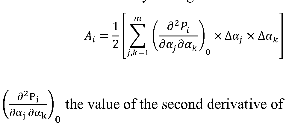
- A the value of the derivative of Pi with respect to the jth surface error parameter o3 ⁇ 4 on the nominal surface and ⁇ 3 ⁇ 4 the value of the jth surface error parameter, and A; a combination of terms of order greater or equal to 2 for each Pi.
- the method according to the invention allows determining a set of optical parameters of a manufactured optical lens by simply measuring the manufactured surface and considering the nominal ophthalmic lens.
- a lens surface measurement is much less time and cost consuming than a lens optical measurement.
- the method according to the invention allows by simply measuring the manufactured surface of an ophthalmic lens determining optical parameters of the ophthalmic lens. Such optical parameters may then be compared to their nominal values and one can check if the quality of the manufactured ophthalmic lens is acceptable, for example based on international quality standards.
- ⁇ during the optical parameter determining step at least part, for example all, of the optical parameters are determined by having:
- the ophthalmic lens is a progressive multifocal ophthalmic lens
- the manufactured surface is a non-symmetric surface
- ⁇ at least one optical parameter is determined, for example all optical parameters are determined, under specific conditions defined by at least a reference point out of the ophthalmic lens and the position and orientation of the ophthalmic lens with respect to the reference point; and/or
- the ophthalmic lens is adapted for a wearer; and/or ⁇ the ophthalmic lens is adapted for a wearer and at least one optical parameter is determined, for example all optical parameters are determined, under given wearing conditions defined by at least a position of one of the surfaces of the ophthalmic lens, for example the rear surface of the ophthalmic lens, with respect to a position of the center of rotation of the eye of the wearer and a pantoscopic angle and a wrap angle of the ophthalmic lens; and/or
- the wearing conditions are defined from measurements on the wearer and a spectacle frame chosen by the wearer;
- ⁇ at least one optical parameter is determined, for example all optical parameters are determined, under usual wearing conditions with a primary viewing direction of the wearer intersecting the fitting cross (CM) of the ophthalmic lens, a distance between the center of rotation of the eye and the rear face of the ophthalmic lens of 27 mm, the pantoscopic angle of 8° and the wrap angle of 0°; and/or
- ⁇ at least one optical parameter is determined, for example all optical parameters are determined, with the ophthalmic lens in a position with relation to the eye of the wearer, defined by the pantoscopic angle of 8°, a lens-pupil distance of 12 mm, a pupil-eye rotation center distance of 13.5 mm and the wrap angle of 0°; and/or
- ⁇ at least one optical parameter is a local optical parameter, for example the at least one optical parameter is selected among the list consisting of: spherical power, astigmatism amplitude and axis, vertical prismatic deviation, horizontal prismatic deviation, total prismatic deviation; and/or
- ⁇ at least one optical parameter is selected in the list of optical parameter defined in one of the standards ISO 8980-1, ISO 8980-2, and ISO 21987; and/or
- ⁇ at least one optical parameters is defined at at least one reference point of the ophthalmic lens, for example the at least one reference point is selected among the list consisting of : the near vision point, the far vision point, the prism reference point, the fitting cross; and/or
- ⁇ at least one optical parameter is a global optical parameter
- the global parameter is defined on a zone corresponding to the intersection of a cone and one of the surfaces of the ophthalmic lens, the axis of the cone passing through the a first reference point out of the ophthalmic lens and a second reference, point located on one of the surfaces of the ophthalmic lens, for example the near vision point, the far vision point, the prism reference point or the fitting cross, the aperture of the cone being greater than or equal to 5°, for example greater than or equal to 10°, and smaller than or equal to 20°, for example smaller than or equal to 15°; and/or
- the ophthalmic lens is adapted for a wearer and the cone is a vision cone, the first reference point is the center of rotation of the eye of the wearer; and/or
- the nominal ophthalmic lens data represent the nominal ophthalmic lens in a nominal frame of reference
- ⁇ the measured manufactured surface of the ophthalmic lens is expressed in the nominal frame of reference;
- the ophthalmic lens is adapted for a wearer and the nominal frame of reference is linked to the wearer;
- the method further comprises:
- the surface error parameter determining step further comprises a zone determining step in which a zone of interest is determined in the nominal surface and the surface error parameters are determined by minimizing the difference between the nominal surface and the composed surface in the zone of interest; and/or
- the parameter determining step is implemented by using a damped least squares process
- the surface error parameters comprise at least six position parameters, for example three translation parameters (T x , T y , T z ) and three rotation parameters (R x , R y , R z ) of the at least one manufactured surface of the ophthalmic lens with respect to the nominal surface; and/or
- the deformation surface corresponds to a sphero-torus surface defined by a sphere parameter, a cylinder parameter and an axis parameter;
- the invention further relates to a method for controlling a lens manufacturing process wherein the lens manufacturing process comprises in addition to the steps of the method according to the invention:
- the invention further relates to a method for controlling a lens manufacturing process comprising the steps of:
- step d) repeating regularly step a) to c) and checking the evolution of the at least one optical parameter over time
- the evolution of at least one parameter of the manufacturing device used during the lens manufacturing process is checked over time and the evolution over time of at least one optical parameter of the master lens is related with the evolution over time of the at least one parameter of the manufacturing device.
- the invention relates to a computer program product comprising one or more stored sequences of instructions that are accessible to a processor and which, when executed by the processor, causes the processor to carry out the steps of the method according to the invention.
- the invention further relates to a computer readable medium carrying one or more sequences of instructions of the computer program product according to the invention.
- the invention relates to a program which makes a computer execute the method of the invention.
- the invention also relates to a computer-readable storage medium having a program recorded thereon; where the program makes the computer execute the method of the invention.
- the invention further relates to a device comprising a processor adapted to store one or more sequence of instructions and to carry out at least one of the steps of the method according to the invention.
- Embodiments of the present invention may include apparatuses for performing the operations herein.
- This apparatus may be specially constructed for the desired purposes, or it may comprise a general purpose computer or Digital Signal Processor ("DSP") selectively activated or reconfigured by a computer program stored in the computer.
- DSP Digital Signal Processor
- Such a computer program may be stored in a computer readable storage medium, such as, but is not limited to, any type of disk including floppy disks, optical disks, CD-ROMs, magnetic-optical disks, read-only memories (ROMs), random access memories (RAMs) electrically programmable read-only memories (EPROMs), electrically erasable and programmable read only memories (EEPROMs), magnetic or optical cards, or any other type of media suitable for storing electronic instructions, and capable of being coupled to a computer system bus.
- a computer readable storage medium such as, but is not limited to, any type of disk including floppy disks, optical disks, CD-ROMs, magnetic-optical disks, read-only memories (ROMs), random access memories (RAMs) electrically programmable read-only memories (EPROMs), electrically erasable and programmable read only memories (EEPROMs), magnetic or optical cards, or any other type of media suitable for storing electronic instructions, and capable of being coupled to a computer system bus.
- FIG. 1 is flowchart representing the steps of a method according to an embodiment of the invention
- FIG. 3 illustrates the cylinder axis YAX in a convention used to characterize an aspherical surface
- FIG. 5 and 6 show referential defined with respect to micro -markings, for a surface bearing micro -markings and for a surface not bearing the micro -markings respectively,
- FIG. 7 and 8 show, diagrammatically, optical systems of eye and lens
- FIG. 9 shows a ray tracing from the center of rotation of the eye
- FIG. 10 is a table illustrating an example of implementation of the invention.
- FIG. 1 1 is a table illustrating a further example of implementation of the invention.
- a progressive lens comprises at least one but preferably two non-rotationally symmetrical aspheric surfaces, for instance but not limited to, progressive surface, regressive surface, toric or atoric surfaces.
- a minimum curvature CURVmi n of a surface is defined at any point on said surface by the formula:
- R max is the maximum radius of curvature of the surface, expressed in meters and CURVmin is expressed in dioptres.
- a maximum curvature CURV max of a surface can be defined at any point on the surface by the formula:
- R m i n is the minimum radius of curvature of the surface, expressed in meters and CURVmax is expressed in dioptres.
- the minimum radius of curvature Rmin and the maximum radius of curvature R max are identical and, accordingly, the minimum and maximum curvatures CURV m i n and CURV max are also identical.
- the local minimum radius of curvature R m i n and the local maximum radius of curvature R max are different.
- the minimum and maximum spheres labeled SPH m i n and SPH max can be deduced according to the kind of surface considered.
- the expressions are the following:
- n is the refractive index of the constituent material of the lens.
- the expressions are the following:
- n is the refractive index of the constituent material of the lens.
- a mean sphere SPH mean at any point on an aspherical surface can also be defined by the formula:
- the expression of the mean sphere therefore depends on the surface considered: if the surface is the object side surface, SPH if the surface is an eyeball side surface, SPH t
- a cylinder CYL is also defined by the formula CY
- any aspherical face of the lens may be expressed by the local mean spheres and cylinders.
- a surface can be considered as locally aspherical when the cylinder is at least 0.25 diopters.
- a local cylinder axis YAX may further be defined.
- Figure 2 illustrates the astigmatism axis ⁇ as defined in the TABO convention and figure 3 illustrates the cylinder axis YAX in a convention defined to characterize an aspherical surface.
- the cylinder axis YAX is the angle of the orientation of the maximum curvature CURVmax with relation to a reference axis and in the chosen sense of rotation.
- the reference axis is horizontal (the angle of this reference axis is 0°) and the sense of rotation is counterclockwise for each eye, when looking at the wearer (0° ⁇ YAX ⁇ 180°).
- An axis value for the cylinder axis YAX of +45° therefore represents an axis oriented obliquely, which when looking at the wearer, extends from the quadrant located up on the right to the quadrant located down on the left.
- Gauss formula enables to express the local sphere SPH along any axis ⁇ , ⁇ being a given angle in the referential defined in figure 3.
- the axis ⁇ is shown in Figure 4.
- SPH(0) SPH ⁇ cos 2 (0 - Yax ) + SPH ⁇ sin 2 (0 - Jax )
- a surface may thus be locally defined by a triplet constituted by the maximum sphere SPH max , the minimum sphere SPH m i n and the cylinder axis YAX.
- the triplet may be constituted by the mean sphere SPH mean , the cylinder CYL and the cylinder axis YAX.
- a referential is defined with respect to micro -markings as illustrated in figures 5 and 6, for a surface bearing micro -markings and for a surface not bearing any micro- markings respectively.
- Progressive lenses comprise micro -markings that have been made mandatory by a harmonized standard ISO 8990-2.
- Temporary markings may also be applied on the surface of the lens, indicating diopter measurement positions (sometimes referred to as control points) on the lens, such as for far vision and for near vision, a prism reference point and a fitting cross for instance.
- FV position far vision diopter measurement position
- NV position near vision diopter measurement position
- micro -markings also make it possible to define referential for both surfaces of the lens.
- Figure 5 shows the referential for the surface bearing the micro -markings.
- MG is the collinear unitary vector defined by the two micro -markings.
- vector Y of the referential is equal to the vector product of Z by MG;
- vector X of the referential is equal to the vector product of Y by Z. ⁇ X, Y, Z ⁇ thereby form a direct orthonormal trihedral.
- the X axis is the horizontal axis and the Y axis is the vertical axis as it shown in Figure 3.
- Figure 6 shows the referential for the surface opposite to the surface bearing the micro -markings.
- Referential of the second surface is constructed the same way as the referential of the first surface, i.e. vector Z is equal to the unitary normal of the second surface; vector Y is equal to the vector product of Z by MG; vector X is equal to the vector product of Y by Z.
- the X axis is the horizontal axis and the Y axis is the vertical axis as it shown in Figure 3.
- Figures 7 and 8 are diagrammatic illustrations of optical systems of eye and lens, thus showing the definitions used in the description. More precisely, figure 7 represents a perspective view of such a system illustrating parameters a and ⁇ used to define a gaze direction.
- Figure 8 is a view in the vertical plane parallel to the anteroposterior axis of the wearer's head and passing through the center of rotation of the eye in the case when the parameter ⁇ is equal to 0.
- the center of rotation of the eye is labeled Q'.
- the axis Q'F' shown on Figure 8 in a dot-dash line, is the horizontal axis passing through the center of rotation of the eye and extending in front of the wearer - that is the axis Q'F' corresponding to the primary gaze view.
- This axis cuts the back surface of the lens on a point called the fitting cross, which is present on lenses to enable the positioning of lenses in a frame by an optician.
- the point of intersection of the rear surface of the lens and the axis Q'F' is the point O.
- O can be the fitting cross if it is located on the rear surface.
- An apex sphere, of center Q', and of radius q' is tangential to the rear surface of the lens in a point of the horizontal axis.
- a value of radius q' of 25.5 mm corresponds to a usual value and provides satisfying results when wearing the lenses.
- a given gaze direction - represented by a solid line on figure 7 - corresponds to a position of the eye in rotation around Q' and to a point J of the apex sphere; the angle ⁇ is the angle formed between the axis Q'F' and the projection of the straight line Q'J on the horizontal plane comprising the axis Q'F'; this angle appears on the scheme on Figure 7.
- the angle a is the angle formed between the axis Q'J and the projection of the straight line Q'J on the horizontal plane comprising the axis Q'F'; this angle appears on the scheme on Figures 7 and 8.
- a given gaze view thus corresponds to a point J of the apex sphere or to a couple ( ⁇ , ⁇ ). The more the value of the lowering gaze angle is positive, the more the gaze is lowering and the more the value is negative, the more the gaze is rising.
- the image of a point M in the object space, located at a given object distance, is formed between two points S and T corresponding to minimum and maximum distances JS and JT, which would be the sagittal and tangential local focal lengths.
- the image of a point in the object space at infinity is formed, at the point F'.
- the distance D corresponds to the rear frontal plane of the lens.
- Ergorama is a function associating to each gaze direction the usual distance of an object point. Typically, in far vision following the primary gaze direction, the object point is at infinity. In near vision, following a gaze direction essentially corresponding to an angle a of the order of 35° and to an angle ⁇ of the order of 5° in absolute value toward the nasal side, the object distance is of the order of 30 to 50 cm.
- US patent US- A-6,318,859 may be considered. This document describes an ergorama, its definition and its modeling method. For a method of the invention, points may be at infinity or not. Ergorama may be a function of the wearer's ametropia.
- An object point M at an object distance given by the ergorama is considered for a gaze direction ( ⁇ , ⁇ ).
- An object proximity ProxO is defined for the point M on the corresponding light ray in the object space as the inverse of the distance MJ between point M and point J of the apex sphere:
- the object proximity can be considered as the inverse of the distance between the object point and the front surface of the lens, on the corresponding light ray.
- the image of a point M having a given object proximity is formed between two points S and T which correspond respectively to minimal and maximal focal distances (which would be sagittal and tangential focal distances).
- the quantity Proxl is called image proximity of the point M:
- an optical power Pui as the sum of the image proximity and the object proximity.
- an astigmatism Ast is defined for every gaze direction and for a given object proximity as :
- This definition corresponds to the astigmatism of a ray beam created by the lens. It can be noticed that the definition gives, in the primary gaze direction, the classical value of astigmatism.
- the astigmatism angle is the angle ⁇ .
- the angle ⁇ is measured in the frame ⁇ Q', x m , y m , z m ⁇ linked to the eye. It corresponds to the angle with which the image S or T is formed depending on the convention used with relation to the direction z m in the plane ⁇ Q', z m , y m ⁇ .
- Possible definitions of the optical power and the astigmatism of the lens, in the wearing conditions can thus be calculated as explained in the article by B.
- Bourdoncle et al entitled "Ray tracing through progressive ophthalmic lenses", 1990 International Lens Design Conference, D.T. Moore ed., Proc. Soc. Photo. Opt. Instrum. Eng. Standard wearing conditions are to be understood as the position of the lens with relation to the eye of a standard wearer, notably defined by a pantoscopic angle of -8°, a lens-pupil distance of 12 mm, a pupil-eye rotation center of 13.5 mm and a wrap angle of 0°.
- the pantoscopic angle is the angle in the vertical plane between the optical axis of the spectacle lens and the visual axis of the eye in the primary position, usually taken to be the horizontal.
- the wrap angle is the angle in the horizontal plane between the optical axis of the spectacle lens and the visual axis of the eye in the primary position, usually taken to be the horizontal.
- Other conditions may be used. Wearing conditions may be calculated from a ray-tracing program, for a given lens. Further, the optical power and the astigmatism may be calculated so that the prescription is either fulfilled at the reference points (i.e control points in far vision) and for a wearer wearing his spectacles in the wearing conditions or measured by a frontofocometer.
- Figure 9 represents a perspective view of a configuration wherein the parameters a and ⁇ are non zero.
- the effect of rotation of the eye can thus be illustrated by showing a fixed frame ⁇ x, y, z ⁇ and a frame ⁇ x m , y m , z m ⁇ linked to the eye.
- Frame ⁇ x, y, z ⁇ has its origin at the point Q'.
- the axis x is the axis Q'O and it is oriented from the lens toward the eye.
- the y axis is vertical and oriented upwardly.
- the z axis is such that the frame ⁇ x, y, z ⁇ be orthonormal and direct.
- the frame ⁇ x m , Ym, z m ⁇ is linked to the eye and its center is the point Q ' .
- the x m axis corresponds to the gaze direction JQ'.
- the two frames ⁇ x, y, z ⁇ and ⁇ x m , y m , z m ⁇ are the same.
- a surface characterization is thus equivalent to an optical characterization. In the case of a blank, only a surface characterization may be used. It has to be understood that an optical characterization requires that the lens has been machined to the wearer's prescription.
- the characterization may be of a surface or optical kind, both characterizations enabling to describe the same object from two different points of view.
- the characterization of the lens refers to the ergorama-eye-lens system described above.
- the term 'lens' is used in the description but it has to be understood as the 'ergorama-eye-lens system'.
- the value in surface terms can be expressed with relation to points. The points are located with the help of abscissa or ordinate in a frame as defined above with respect to figures 3, 5 and 6.
- Gaze directions are usually given by their degree of lowering and azimuth in a frame whose origin is the center of rotation of the eye.
- a point called the fitting cross is placed before the pupil or before the eye rotation center Q' of the eye for a primary gaze direction.
- the primary gaze direction corresponds to the situation where a wearer is looking straight ahead.
- the fitting cross corresponds thus to a lowering angle a of 0° and an azimuth angle ⁇ of 0° whatever surface of the lens the fitting cross is positioned - back surface or front surface.
- the "upper" part of the surface of a lens - or of a semi-finished lens blank - corresponds to a positive value along the y axis, and preferably to a value along the y axis superior to the y value at the fitting cross and the "lower" part of the surface of a lens - or of a semi- finished lens blank - corresponds to a negative value along the y axis in the frame as defined above with respect to figures 3, 5 and 6, and preferably to a value along the y axis inferior to the y value at the fitting cross.
- the method according to the invention is a method for determining the values of a set of n optical parameters (Pi, P 2 , ... , P n ) of an ophthalmic lens, n being an integer greater than or equal to 1.
- the ophthalmic lens may be a single vision ophthalmic lens, a multifocal ophthalmic lens, or a progressive multifocal ophthalmic lens.
- the ophthalmic lens may be a master lens.
- the master lens is a lens that is not intended to be worn by a wearer.
- the master lens may have different geometrical and/or optical parameter and/or is made of a different material than the lenses intended to be worn by a wearer.
- the master lens is made of a material and has a design such as its optical parameters are more sensible to a modification of the process parameter that the usual manufactured lenses.
- the ophthalmic lens may be adapted for a wearer; in particular the ophthalmic lens may be adapted to the prescription of the wearer.
- At least one optical parameter Pi is determined, for example all optical parameters (Pi, P 2 , P n ) are determined, under specific conditions defined by at least a reference point out of the ophthalmic lens and the position and orientation of the ophthalmic lens with respect to the reference point.
- the specific conditions may be wearing conditions and the reference point may represent a center of rotation of an eye of a wearer.
- the position and orientation of the ophthalmic lens may be defined by the position the position of one of the surfaces of the ophthalmic lens, for example the rear surface of the ophthalmic lens, with respect to a position of the center of rotation of the eye of the wearer and a pantoscopic angle and a wrap angle of the ophthalmic lens.
- the wearing conditions may be obtained by specific measurements on the wearer, thus increasing the accuracy of the method according to the invention.
- Usual wearing conditions may also be used to define at least one, for example all, of the optical parameters.
- Usual wearing conditions may be defined by a primary viewing direction of the wearer intersecting the fitting cross of the ophthalmic lens, a distance between the center of rotation of the eye and the rear face of the ophthalmic lens of 27 mm, the pantoscopic angle of 8° and the wrap angle of 0°.
- usual wearing conditions may be defined considering the pupil of the wearer.
- Such wearing conditions may be defined by a pantoscopic angle of 8°, a lens-pupil distance of 12 mm, a pupil-eye rotation center distance of 13.5 mm and a wrap angle of 0°.
- At least one optical parameter is a local optical parameter.
- the optical parameters may be selected among the list consisting spherical power, astigmatism amplitude and axis, vertical prismatic deviation, horizontal prismatic deviation, total prismatic deviation.
- optical parameters are defined in the ISO standard:
- Each local optical parameter can be defined at a reference point.
- the reference point may be selected in the list consisting of: the near vision point, the far vision point, the prism reference point, the fitting cross.
- At least one optical parameter is a global optical parameter.
- the global optical parameter is defined on a zone corresponding to the intersection of a cone and one of the surfaces of the ophthalmic lens.
- the axis of the cone passes through a first and second reference points.
- the first reference point is a point situated out of the ophthalmic lens and the second reference is point located on one of the surfaces of the ophthalmic lens.
- the cone may be a vision cone and the first reference point is than the center of rotation of the eye.
- the first reference point may correspond to the center of rotation of the eye of the wearer.
- the second reference point may be in the case of a multifocal ophthalmic lens the near vision point, the far vision point, the prism reference point or the fitting cross.
- the aperture of the cone is greater than or equal to 5°, for example greater than or equal to 10°, and smaller than or equal to 20°, for example smaller than or equal to 15°.
- the method of the invention may comprise:
- nominal data representing a nominal ophthalmic lens is provided.
- the nominal data may represent the nominal ophthalmic in a nominal frame of reference.
- such nominal frame of reference may be linked to the wearer.
- an ophthalmic lens is provided.
- the ophthalmic lens comprises at least two optical surfaces at least one of which is manufactured based on the corresponding surface of the nominal ophthalmic lens also named "nominal surface”.
- At least one manufactured surface of the ophthalmic lens is measured.
- the measured manufactured surface of the ophthalmic lens is expressed in the nominal frame of reference used to express the nominal ophthalmic lens.
- a set of m surface error parameters (a l s a 2 , ..., a m ) is determined, m being an integer greater than or equal to 1.
- the surface error parameters represent the differences in position and/or shape of the measure optical surface and the corresponding surface of the nominal ophthalmic lens.
- the method further comprises:
- a surface error parameter determining step S43 During the deformation surface providing step S41, at least one deformation surface defined by at least one surface error parameter (o3 ⁇ 4) is provided.
- the deformation surface may correspond to a sphero-torus surface defined by a sphere parameter, a cylinder parameter and an axis parameter.
- the deformation surface may further correspond to a right circular cone defined by an axis parameter and an angle parameter.
- the surface error parameter comprise at least six position parameters, for example three translation parameters (T x , T y , T z ) and three rotation parameters (R x , R y , R z ) of the at least one manufactured surface of the ophthalmic lens with respect to the nominal surface.
- a composed surface is determined by adding the measured manufactured surface and the at least one deformation surface.
- the values of surface error parameters ( ⁇ 3 ⁇ 4) are determined by minimizing the difference between the nominal surface and the composed surface, for example using a damped least squares process.
- the surface error parameter determining step further comprises a zone determining step in which a zone of interest is determined in the nominal surface and the surface error parameters are determined by minimizing the difference between the nominal surface and the composed surface in the zone of interest.
- the inventors have implemented the method according to the invention to determine the influence of a set of surface errors over a set of optical parameters for a given an ophthalmic lens.
- the ophthalmic lens is a progressive addition lens.
- the front surface of the ophthalmic lens has a base curve of 5.5 diopters, an Addition of 2.0 diopters and a "Comfort Varilux" design.
- the back surface of the optical lens is spherical and arranged to provide at the near vision point an ophthalmic prescription of 2.0 diopters of sphere, 0 diopter of cylinder and 0° of Axis.
- the optical lens is made of an Orma material having a refractive index of
- the thickness of the optical lens is of at least 0.8 mm along a circle of 60 mm of diameter centered on the prism reference point of the ophthalmic lens.
- the thickness of the optical lens at the prism reference point is greater than 2.5 mm.
- the inventors have chosen to consider the following positioning errors among the surface errors:
- D Rx the rotation positioning error of the back surface of the ophthalmic lens relative to the front surface of the ophthalmic lens about the x axis
- D Ry the rotation positioning error of the back surface of the ophthalmic lens relative to the front surface of the ophthalmic lens about the y axis
- optical prismatic effect of the above mentioned surface errors have also been evaluated at the prism reference point of the ophthalmic lens by considering the horizontal prismatic deviation at the prism reference point Dh_prp and the vertical prismatic deviation at the prism reference point Dv_prp.
- the table of figure 10 can be used to determine the optical properties of a manufactured ophthalmic lens based on measured surface errors.
- the ophthalmic lens when the ophthalmic lens has been manufactured, one may measure the surface errors D Tx, D Ty, D Tz, D Rx, D Ry, D Rz, D xx, D xy and D yy and estimate the expected value of the optical parameters using the table of figure 10.
- the difference between the nominal value of the average optical power at the far vision point Pfv_45,0 and the obtained value of said average optical power at the far vision point Pfv_45 can be estimated to be equal to :
- the table provided in figure 10 can also be use line by line so as to determine for each surface error the most impacted optical parameters. For example, the considering the tilting errors D xx, D xy and D yy when analyzing the table of figure 10 line by line it appears that such tilting errors of the back surface of the lens have a small impact on the horizontal and vertical prismatic deviations whereas the same tilting error have a great impact on the value of the optical powers at the near and far vision points.
- the table of figure 10 may also be used row by row so as to determine the surface errors that influence the most a given optical parameter.
- the optical power parameters Pfv_45, Pfv_30, Pfv_60, Pnv_45, Pnv_30 and Pnv_60 are influenced mainly by the tilting errors D xx, D xy and D yy.
- D Tx the translation positioning error of the back surface of the ophthalmic lens relative to the front surface of the ophthalmic lens along the x axis and also by;
- the inventors have further implemented the method according to the invention to with a progressive addition lens similar to the one of example 1 with a front surface of the ophthalmic lens has a base curve of 5.5 diopters, an Addition of 3.5 diopters and a "Comfort Varilux" design.
- the back surface of the optical lens is spherical and arranged to provide at the near vision point an ophthalmic prescription of 0 diopter of sphere, 3 diopters of cylinder and 30° of Axis.
- the optical lens is made of an Orma material having a refractive index of
- the thickness of the optical lens is of at least 0.8 mm along a circle of 60 mm of diameter centered on the prism reference point of the ophthalmic lens.
- the thickness of the optical lens at the prism reference point is of at least 2.5 mm.
- the optical parameters and the surface errors are the same as for example 1. As in example 1, for each optical parameter Pi the value of the derivative of Pi with respect to the each surface error parameters has been evaluated.
- the method according of the invention can be used for double surfacing manufacturing process, i.e. processes during which both the front and back surfaces of the ophthalmic lens are machined.
Abstract
Description


Claims


Priority Applications (7)
| Application Number | Priority Date | Filing Date | Title |
|---|---|---|---|
| BR112015011026-6A BR112015011026B1 (en) | 2012-11-14 | 2013-11-13 | method of determining optical parameters of an ophthalmic lens |
| KR1020157012542A KR102100726B1 (en) | 2012-11-14 | 2013-11-13 | Method of determining optical parameters of an ophthalmic lens |
| CN201380059425.3A CN104781644B (en) | 2012-11-14 | 2013-11-13 | The method for determining the optical parametric of ophthalmic len |
| CA2891559A CA2891559A1 (en) | 2012-11-14 | 2013-11-13 | Method of determining optical parameters of an opthalmic lens |
| US14/442,945 US9671618B2 (en) | 2012-11-14 | 2013-11-13 | Method of determining optical parameters of an ophthalmic lens |
| EP13805785.6A EP2920568B1 (en) | 2012-11-14 | 2013-11-13 | Method of determining optical parameters of an opthalmic lens |
| MX2015006029A MX347526B (en) | 2012-11-14 | 2013-11-13 | Method of determining optical parameters of an opthalmic lens. |
Applications Claiming Priority (2)
| Application Number | Priority Date | Filing Date | Title |
|---|---|---|---|
| EP12306415 | 2012-11-14 | ||
| EP12306415.6 | 2012-11-14 |
Publications (1)
| Publication Number | Publication Date |
|---|---|
| WO2014076155A1 true WO2014076155A1 (en) | 2014-05-22 |
Family
ID=47358566
Family Applications (1)
| Application Number | Title | Priority Date | Filing Date |
|---|---|---|---|
| PCT/EP2013/073767 WO2014076155A1 (en) | 2012-11-14 | 2013-11-13 | Method of determining optical parameters of an opthalmic lens |
Country Status (9)
| Country | Link |
|---|---|
| US (1) | US9671618B2 (en) |
| EP (1) | EP2920568B1 (en) |
| KR (1) | KR102100726B1 (en) |
| CN (1) | CN104781644B (en) |
| BR (1) | BR112015011026B1 (en) |
| CA (1) | CA2891559A1 (en) |
| CO (1) | CO7350644A2 (en) |
| MX (1) | MX347526B (en) |
| WO (1) | WO2014076155A1 (en) |
Cited By (2)
| Publication number | Priority date | Publication date | Assignee | Title |
|---|---|---|---|---|
| US10352816B2 (en) | 2014-11-11 | 2019-07-16 | Brien Holden Vision Institute Limited | Systems and methods for determining the quality of a reproduced (manufactured) optic device |
| DE102020004840A1 (en) | 2020-08-07 | 2022-02-10 | Rodenstock Gmbh | Improved calculation of ophthalmic lenses |
Families Citing this family (6)
| Publication number | Priority date | Publication date | Assignee | Title |
|---|---|---|---|---|
| BR112015011025B1 (en) * | 2012-11-14 | 2021-02-23 | Essilor International | method, implanted by means of a computer, to determine the viability of an ophthalmic lens by an ophthalmic lens manufacturing process |
| US10471566B2 (en) * | 2014-08-13 | 2019-11-12 | Essilor International | Method for determining location of a lens machining tool in a turning machine configured for machining ophtalmic lenses |
| KR102329814B1 (en) * | 2014-12-01 | 2021-11-22 | 삼성전자주식회사 | Pupilometer for 3d display |
| US10379381B2 (en) * | 2015-06-08 | 2019-08-13 | Johnson & Johnson Vision Care, Inc. | Contact lens with optimized performance and method of design |
| KR20180060559A (en) * | 2016-11-29 | 2018-06-07 | 삼성전자주식회사 | Method and apparatus for determining inter-pupilary distance |
| DE102022200462B3 (en) | 2022-01-17 | 2023-03-30 | Rodenstock Gmbh | Computer-implemented method for determining a manufacturing correction model for the manufacture of ophthalmic lenses, storage device, computer program product, method and apparatus |
Citations (3)
| Publication number | Priority date | Publication date | Assignee | Title |
|---|---|---|---|---|
| WO1999066308A1 (en) * | 1998-06-18 | 1999-12-23 | Optikos Corporation | Automated optical measurement apparatus and method |
| US6318859B1 (en) | 1996-09-20 | 2001-11-20 | Essilor International | Set of progressive multifocal ophthalmic lenses |
| EP2369319A2 (en) * | 2010-03-23 | 2011-09-28 | Fujifilm Corporation | Aspheric object measuring method and apparatus |
Family Cites Families (7)
| Publication number | Priority date | Publication date | Assignee | Title |
|---|---|---|---|---|
| CN100419378C (en) * | 2005-06-23 | 2008-09-17 | 麦克奥迪实业集团有限公司 | Apparatus and method for testing aspherical surface shape error of optical lens |
| WO2009028685A1 (en) * | 2007-08-31 | 2009-03-05 | Hoya Corporation | Method and device for evaluating graduated refraction power lens and method for manufacturing graduated refraction power lens |
| AU2010246171B2 (en) * | 2009-05-04 | 2014-02-13 | Coopervision International Limited | Use of accommodative error measurements in providing ophthalmic lenses |
| WO2012014810A1 (en) * | 2010-07-27 | 2012-02-02 | Hoya株式会社 | Eyeglass lens evaluation method, eyeglass lens design method, eyeglass lens manufacturing method, eyeglass lens manufacturing system, and eyeglass lens |
| CN201867177U (en) * | 2010-11-19 | 2011-06-15 | 福建师范大学 | Device for detecting surface deviation of lens |
| EP2522458B1 (en) * | 2011-05-13 | 2016-07-06 | ESSILOR INTERNATIONAL (Compagnie Générale d'Optique) | Process for determining position parameters of a manufactured surface relative to a reference surface |
| CN102661855A (en) * | 2012-05-31 | 2012-09-12 | 上海理工大学 | Method and system for progressive additional lens detection based on optical coherence tomography |
-
2013
- 2013-11-13 BR BR112015011026-6A patent/BR112015011026B1/en active IP Right Grant
- 2013-11-13 WO PCT/EP2013/073767 patent/WO2014076155A1/en active Application Filing
- 2013-11-13 EP EP13805785.6A patent/EP2920568B1/en active Active
- 2013-11-13 KR KR1020157012542A patent/KR102100726B1/en active IP Right Grant
- 2013-11-13 MX MX2015006029A patent/MX347526B/en active IP Right Grant
- 2013-11-13 CN CN201380059425.3A patent/CN104781644B/en active Active
- 2013-11-13 US US14/442,945 patent/US9671618B2/en active Active
- 2013-11-13 CA CA2891559A patent/CA2891559A1/en not_active Abandoned
-
2015
- 2015-05-15 CO CO15111713A patent/CO7350644A2/en unknown
Patent Citations (3)
| Publication number | Priority date | Publication date | Assignee | Title |
|---|---|---|---|---|
| US6318859B1 (en) | 1996-09-20 | 2001-11-20 | Essilor International | Set of progressive multifocal ophthalmic lenses |
| WO1999066308A1 (en) * | 1998-06-18 | 1999-12-23 | Optikos Corporation | Automated optical measurement apparatus and method |
| EP2369319A2 (en) * | 2010-03-23 | 2011-09-28 | Fujifilm Corporation | Aspheric object measuring method and apparatus |
Non-Patent Citations (1)
| Title |
|---|
| B. BOURDONCLE ET AL.: "International Lens Design Conference", 1990, article "Ray tracing through progressive ophthalmic lenses" |
Cited By (4)
| Publication number | Priority date | Publication date | Assignee | Title |
|---|---|---|---|---|
| US10352816B2 (en) | 2014-11-11 | 2019-07-16 | Brien Holden Vision Institute Limited | Systems and methods for determining the quality of a reproduced (manufactured) optic device |
| US10670495B2 (en) | 2014-11-11 | 2020-06-02 | Brien Holden Vision Institute Limited | Systems and methods for determining the quality of a reproduced (manufactured) optic device |
| DE102020004840A1 (en) | 2020-08-07 | 2022-02-10 | Rodenstock Gmbh | Improved calculation of ophthalmic lenses |
| WO2022029150A1 (en) | 2020-08-07 | 2022-02-10 | Rodenstock Gmbh | Improved calculation of ophthalmological lenses |
Also Published As
| Publication number | Publication date |
|---|---|
| BR112015011026B1 (en) | 2021-05-25 |
| MX347526B (en) | 2017-04-27 |
| BR112015011026A8 (en) | 2018-08-14 |
| EP2920568B1 (en) | 2018-05-16 |
| CN104781644A (en) | 2015-07-15 |
| CN104781644B (en) | 2017-11-03 |
| EP2920568A1 (en) | 2015-09-23 |
| MX2015006029A (en) | 2016-02-05 |
| KR20150081288A (en) | 2015-07-13 |
| KR102100726B1 (en) | 2020-04-14 |
| CA2891559A1 (en) | 2014-05-22 |
| US9671618B2 (en) | 2017-06-06 |
| US20150286069A1 (en) | 2015-10-08 |
| BR112015011026A2 (en) | 2017-07-11 |
| CO7350644A2 (en) | 2015-08-10 |
Similar Documents
| Publication | Publication Date | Title |
|---|---|---|
| EP2920568B1 (en) | Method of determining optical parameters of an opthalmic lens | |
| US9482884B2 (en) | Method of determining an ophthalmic lens | |
| US10365503B2 (en) | Method implemented by computer means for calculating a lens optical system of a spectacle ophthalmic lens for a wearer | |
| EP3143458B1 (en) | A progressive multifocal lens having an enlarged intermediate distance vision region | |
| KR20200057709A (en) | Methods for evaluating ocular lenses, associated evaluation systems and industrial assemblies for manufacturing ocular lenses | |
| US10451894B2 (en) | Method for comparing a first ophthalmic lens with a second ophthalmic lens | |
| US10983365B2 (en) | Method of modifying an dioptric function of an ophthalmic lens surface | |
| US20140354944A1 (en) | Method for Determining a Progressive Opthalmic Lens and a Set of Semi Finished Lens Blanks | |
| EP2920640B1 (en) | Method for determining the feasibility of an ophthalmic lens | |
| AU2014280078B2 (en) | Method for optimizing a measured contour of a spectacle frame | |
| AU2014280079B2 (en) | Method for optimizing an optical surface | |
| US11460717B2 (en) | Set of ophthalmic lenses |
Legal Events
| Date | Code | Title | Description |
|---|---|---|---|
| 121 | Ep: the epo has been informed by wipo that ep was designated in this application |
Ref document number: 13805785 Country of ref document: EP Kind code of ref document: A1 |
|
| ENP | Entry into the national phase |
Ref document number: 2891559 Country of ref document: CA Ref document number: 20157012542 Country of ref document: KR Kind code of ref document: A |
|
| WWE | Wipo information: entry into national phase |
Ref document number: MX/A/2015/006029 Country of ref document: MX |
|
| WWE | Wipo information: entry into national phase |
Ref document number: 14442945 Country of ref document: US |
|
| NENP | Non-entry into the national phase |
Ref country code: DE |
|
| WWE | Wipo information: entry into national phase |
Ref document number: 15111713 Country of ref document: CO |
|
| REG | Reference to national code |
Ref country code: BR Ref legal event code: B01A Ref document number: 112015011026 Country of ref document: BR |
|
| WWE | Wipo information: entry into national phase |
Ref document number: 2013805785 Country of ref document: EP |
|
| ENP | Entry into the national phase |
Ref document number: 112015011026 Country of ref document: BR Kind code of ref document: A2 Effective date: 20150513 |