WO2014067331A1 - 随机接入信道的传输及接收方法和设备 - Google Patents
随机接入信道的传输及接收方法和设备 Download PDFInfo
- Publication number
- WO2014067331A1 WO2014067331A1 PCT/CN2013/082427 CN2013082427W WO2014067331A1 WO 2014067331 A1 WO2014067331 A1 WO 2014067331A1 CN 2013082427 W CN2013082427 W CN 2013082427W WO 2014067331 A1 WO2014067331 A1 WO 2014067331A1
- Authority
- WO
- WIPO (PCT)
- Prior art keywords
- uplink subframe
- prach
- user equipment
- prach signal
- signal
- Prior art date
- Legal status (The legal status is an assumption and is not a legal conclusion. Google has not performed a legal analysis and makes no representation as to the accuracy of the status listed.)
- Ceased
Links
Classifications
-
- H—ELECTRICITY
- H04—ELECTRIC COMMUNICATION TECHNIQUE
- H04W—WIRELESS COMMUNICATION NETWORKS
- H04W74/00—Wireless channel access
- H04W74/08—Non-scheduled access, e.g. ALOHA
Definitions
- the present invention relates to the field of wireless communications, and in particular, to a method and device for transmitting and receiving a random access channel. Background technique
- MTC Machine Type Communications
- LTE Long Term Evolution
- An MTC device ie, MTC user device
- M2M Machine to Machine
- GSM Global System for Mobile Communications
- the deep coverage of the network in these scenarios will greatly increase the network construction cost, including increasing equipment expenditure, network planning cost, and increase.
- the M2M service will be deployed in the LTE network. Therefore, the operator hopes to effectively increase the coverage of the network in the subsequent LTE-based wireless communication technology, and solve the problem in the above scenario.
- User device coverage issues
- the coverage of the LTE system and the GSM system are equivalent.
- the coverage performance of the existing LTE network needs to be improved.
- the coverage needs to be increased by 20 dB compared to the coverage of the existing LTE network.
- the physical channel in the LTE system needs to be covered and enhanced.
- the physical random access channel (PRACH) is a physical channel with better coverage, but it cannot be satisfied.
- M2M communication aims to combine various different types of communication technologies, such as: machine-to-machine communication, machine control communication, human-computer interaction communication, mobile interconnection communication, thereby promoting social production and life.
- machine-to-machine communication machine control communication
- human-computer interaction communication human-computer interaction communication
- mobile interconnection communication mobile interconnection communication
- the current mobile communication network is designed for the communication characteristics between people, such as: determinism of network capacity Wait. If you want to use mobile communication networks to support small-bandwidth system communication, you need to optimize the mechanism of the mobile communication system according to the characteristics of small-bandwidth system communication, so that it can be used in the case of traditional human-to-human communication is not affected or less affected. Under, better communication of small bandwidth systems.
- MTC user equipment has low mobility; the time for data transmission between the MTC user equipment and the network side is controllable, that is, the MTC user equipment can only be within the time period specified by the network. Access is made; the data transmission performed by the MTC user equipment and the network side does not require real-time performance, that is: time tolerance; MTC user equipment energy is limited, requiring extremely low power consumption; between the MTC user equipment and the network side Only small amount of information is transmitted; MTC user equipment can be managed in groups; and so on.
- An actual MTC user equipment may have one or more of the above characteristics.
- the PRACH is used to carry the transmission of the random access preamble (Preamble) sequence, and the base station establishes uplink synchronization by detecting the Preamble sequence and subsequent signaling exchange.
- Preamble random access preamble
- the basic structure of the PRACH signal transmitted on the PRACH is as shown in FIG. 1.
- the main function of the Cyclic Prefix (CP) is to ensure that the receiving end can perform frequency domain detection and resist interference between symbols; CP uses cyclically shifted Zadoff-Chu sequence; when performing Preamble sequence transmission, Uplink synchronization has not yet been established, so Guard Time (GT) needs to be reserved after the Preamble sequence to avoid interference with other users.
- CP Cyclic Prefix
- GT Guard Time
- the reserved GT needs to support the transmission distance to be twice the radius of the cell. This is because the user equipment does not know the distance between itself and the base station when transmitting the Preamble sequence.
- the size of the GT must ensure that the user equipment at the cell edge obtains the downlink frame timing. After that, there can be enough time to send in advance, as shown in Figure 2a (inter-cell user) and Figure 2b (cell edge user).
- the existing methods mainly have the following disadvantages:
- the preamble sequence has a short duration and limited gain, which does not meet the coverage requirements.
- Embodiments of the present invention provide a method and a device for transmitting and receiving a random access channel, which are used to enhance PRACH.
- a method for transmitting a random access channel PRACH comprising:
- the user equipment determines an initial transmission time of the PRACH signal
- the user equipment transmits the PRACH signal on the uplink subframe included in the N uplink subframe groups, starting from the initial transmission time;
- each uplink subframe group includes an uplink for transmitting a PRACH signal.
- a method for receiving a random access channel PRACH comprising:
- the network side determines an initial sending time of the PRACH signal sent by the user equipment
- the network side receives the PRACH signal sent by the user equipment in the uplink subframe included in the N uplink subframe groups, starting from the initial transmission time;
- N is an integer greater than 1, and each uplink subframe group includes one uplink subframe or multiple consecutive uplink subframes configured by the network side for transmitting the PRACH signal.
- a user equipment comprising:
- a determining unit configured to determine a starting transmission time of the PRACH signal
- a transmitting unit configured to upload a PRACH signal in an uplink subframe included in the N uplink subframe groups, starting from the initial transmission time
- each uplink subframe group includes one uplink subframe or multiple consecutive uplink subframes for transmitting the PRACH signal.
- a base station comprising:
- a determining unit configured to determine a start sending time of the PRACH signal sent by the user equipment
- a receiving unit configured to receive, according to the initial sending time, a PRACH signal sent by the user equipment in an uplink subframe included in the N uplink subframe groups;
- N is an integer greater than 1, and each uplink subframe group includes one uplink subframe or multiple consecutive uplink subframes configured by the network side for transmitting the PRACH signal.
- the user equipment transmits on the uplink subframe included in the N uplink subframe groups.
- each uplink subframe group includes one uplink subframe or multiple consecutive uplink subframes. It can be seen that the PRACH signal transmitted in the scheme continues compared with the prior art. The longer time, which increases the signal transmission gain and enhances the coverage of the PRACH.
- FIG. 1 is a schematic structural diagram of a random access channel signal in the prior art
- FIG. 2 is a timing diagram of a random access Preamble sequence of a user in a cell in the prior art
- FIG. 2 is a timing diagram of a random access Preamble sequence of a cell edge user in the prior art
- FIG. 3 is a schematic diagram of a method according to an embodiment of the present invention. Schematic diagram of the process;
- FIG. 5a is a schematic diagram of PRACH signal transmission according to Embodiment 1 of the present invention
- FIG. 5b is a schematic flowchart of an execution process according to Embodiment 1 of the present invention
- FIG. 5a is a schematic diagram of PRACH signal transmission according to Embodiment 1 of the present invention
- FIG. 5b is a schematic flowchart of an execution process according to Embodiment 1 of the present invention
- FIG. 5a is a schematic diagram of PRACH signal transmission according to Embodiment 1 of the present invention
- FIG. 5b is a schematic flowchart of an execution process according to Embodiment 1 of the present invention
- FIG. 5c is a schematic diagram of PRACH signal transmission according to Embodiment 2 of the present invention.
- FIG. 5 is a schematic diagram of an execution flow of Embodiment 2 of the present invention.
- 5e is a schematic diagram of PRACH signal transmission according to Embodiment 3 of the present invention.
- FIG. 5f is a schematic flowchart of an execution process according to Embodiment 3 of the present invention.
- 5G is a schematic diagram of a method for receiving, by a base station, a PRACH signal according to Embodiment 3 of the present invention.
- FIG. 6 is a schematic structural diagram of a user equipment according to an embodiment of the present disclosure.
- FIG. 7 is a schematic structural diagram of a base station according to an embodiment of the present invention. detailed description
- the embodiment of the present invention provides a PRACH transmission method.
- a PRACH transmission method provided by an embodiment of the present invention includes the following steps:
- Step 30 The user equipment determines an initial sending time of the PRACH signal.
- Step 31 The user equipment transmits a PRACH signal on an uplink subframe included in the N uplink subframe groups, where the N is an integer greater than 1, and each uplink subframe group includes An uplink subframe or a plurality of consecutive uplink subframes of the PRACH signal are transmitted.
- step 31 the user equipment transmits the PRACH signal in the uplink subframe included in the N uplink subframe groups, and the specific implementation may be as follows:
- the user equipment transmits a PRACH signal on the uplink subframe included in the uplink subframe group, and the structure of each PRACH signal may be as shown in FIG.
- a newly defined structure including a CP and a random access Preamble sequence can be used; for example, for uplink and downlink configuration 0, subframes 2, 3, and 4 constitute one uplink subframe group, and subframes 7, 8, and 9 constitute one.
- the uplink subframe group, the uplink subframe group including the three uplink subframes may transmit the PRACH signal corresponding to the Preamble format 3 in Table 1; the subframes 2 and 3 may also constitute an uplink subframe including two uplink subframes.
- the frame group can transmit the PRACH signals corresponding to Preamble format 1 and Preamble format 2 in Table 1.
- Subframe 2 and subframe 3 respectively constitute an uplink subframe group including one uplink subframe, and may transmit a PRACH signal corresponding to Preamble format 0 in Table 1; at this time, a random access Preamble sequence in each PRACH signal transmitted
- the scheme can be used for the repetition of the PRACH signal, and the duration of the PRACH signal is increased, thereby improving the signal transmission gain and enhancing the coverage of the PRACH; or, the user equipment is included in the uplink of the N uplink subframe groups.
- a PRACH signal is transmitted on the subframe; at this time, each random access Preamble sequence in the PRACH signal may be the same; the scheme increases the signal transmission gain by increasing the duration of one PRACH signal, and enhances the coverage of the PRACH.
- Preamble format 4 can only be transmitted in the Uplink Pilot Time Slot (UpPTS) domain.
- UpPTS Uplink Pilot Time Slot
- Time Division Synchronous Code Division Multiple Access -
- the TD-SCDMA Long Term Evolution (TD-LTE) system supports seven different uplink and downlink subframe configurations, as shown in Table 2 below.
- the user equipment transmits a PRACH signal on an uplink subframe included in the N uplink subframe groups, and the specific implementation may be as follows:
- the user equipment transmits a CP signal with a length of T C p and a random access Preamble sequence of SEQ 1 with a duration of T seq1 on an uplink subframe included in the first uplink subframe group of the N uplink subframe groups, at N a random access Preamble sequence SEQi with a transmission duration of T se qi on an uplink subframe included in the ith uplink subframe group in the uplink subframe group, where
- the value range of i is [2, N]; wherein, the CP signal is the sequence signal of the last segment of the SEQN with a length of Tcp.
- the scheme reduces the proportion of the CP signal in the PRACH signal, and improves the proportion of the useful signal.
- the PRACH channel can directly extend the existing format, that is, the repetition of the extended sequence.
- the PRACH structure of the TDD-LTE obtained by the base station side is consistent with the PRACH structure in the FDD-LTE, so that the fusion of the two systems can be implemented.
- T is the duration of the uplink subframe group.
- SEQ1 and SEQi may be composed of integer or non-integer basic random access Preamble sequences.
- SEQ1, SEQ2, ..., SEQN can form M basic random access Preamble sequences end-to-end in time sequence; M is an integer greater than 1; wherein the basic random access Preamble sequence is defined in 3GPP Release 11 and previous versions In the PRACH signal of Preamble format 0, the signal sequence after CP is removed.
- the user equipment determines the initial transmission time of the PRACH signal, and the specific implementation may be as follows: the user equipment determines a time period of the PRACH resource and a time offset value of the initial transmission time of the PRACH signal in the time period;
- k is an integer that is not less than 0 and is not greater than the maximum value of the number of uplink subframe groups included in each radio frame.
- the value of k may be pre-agreed by the user equipment and the network side, or may be pre-defined by the network side. The value of k is notified to the user equipment, that is, the user equipment determines the value of k according to the configuration information sent in advance by the network side.
- the user equipment may determine the initial sending time of the PRACH signal according to the time period and the time offset value of the PRACH resource, and the time period and the time offset value of the PRACH resource are both maintained by the user equipment and the network side, so that The user equipment and the base station can understand the transmission timing of the PRACH signal, thereby ensuring the accuracy of the PRACH signal detection.
- the first preset condition can be:
- E HANCEDPRACH_STARTFRAMEOFFSET is the determined time offset value
- the unit is the radio frame
- T is the determined time period
- the unit is the radio frame.
- the second preset condition can be:
- SFN is the system frame number of the radio frame
- E HANCEDPRACH_STARTFRAMEOFFSET is the determined time offset value
- the unit is the uplink subframe group
- T is the determined time period
- the unit is the radio frame.
- the method for the user equipment to determine the time period of the PRACH resource may be as follows: the user equipment and the network side pre-arrange the time period of the PRACH resource, or determine the time period of the PRACH resource according to the configuration information sent in advance by the network side;
- the method for the user equipment to determine the time offset value of the initial transmission time of the PRACH signal in the time period may be as follows: The user equipment and the network side pre-arrange the time offset value of the initial transmission time of the PRACH signal in the time period, Or determining a time offset value of the initial transmission time of the PRACH signal in the time period according to the configuration information pre-transmitted by the network side.
- TDD Time Division Duplex
- the index number of the first physical resource block that can be used to transmit the PRACH is defined as the parameter 1 ⁇ 2 ⁇ "is the physical resource block number given by the upper layer, The value range is: w PRBoffset - B _ u ,
- the index number of the first physical resource block that can be used to transmit the PRACH is the sequence number of the lowest end PRB of the band or the sequence number of the highest-end PRB.
- each PRACH should follow the principle of a certain D ⁇ , first-time domain mapping, if there is not enough resources in the time domain to accommodate all PRACH and then perform frequency domain mapping.
- D ⁇ first-time domain mapping
- frequency division principle is followed. The following formula - proceed:
- ⁇ ⁇ is the number of uplink resource blocks (RBs), which is the first one that can be used for a certain PRACH channel transmission.
- the resource block index number, "P ⁇ " is the first resource block index number that can be used for the PRACH mapping in the subframe, and represents the channel resource number of the PRACH. It can be known that: PRACH resources of format 0-3 use a bilateral mapping method to sequentially allocate resources. For format 4, the frequency resource mapping is performed according to the following formula 2:
- n f is the system frame number
- N sp is the number of uplink and downlink subframe switching points in one radio frame.
- the frequency domain resource used by the user equipment to transmit the PRACH signal in the uplink subframe included in the N uplink subframe groups may be the same as the frequency domain resource used in the PRACH in the prior art.
- Different, frequency domain resources that are not used at the same time can be determined as follows:
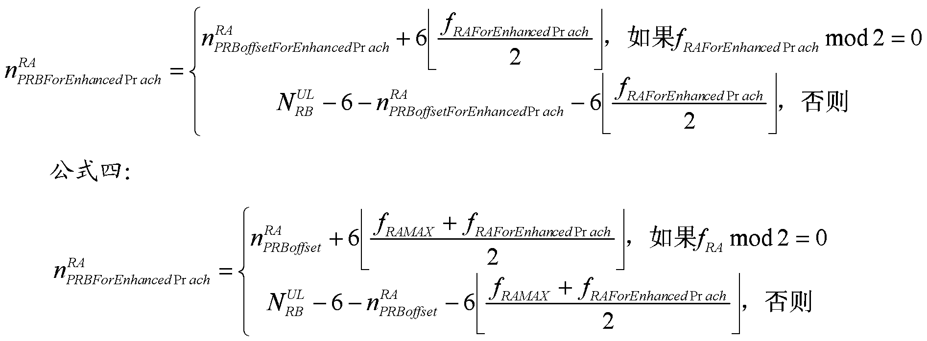
- the first physical resource block (PRB) for PRACH signal transmission is determined according to the following formula 3 or formula 4.
- the transmitted PRACH signal is in Preamble format 4
- the first one is determined according to Equation 3 below.
- V is the number of uplink resource blocks (RBs), " ⁇ . ⁇ is the first one specified in the ⁇ system.
- the PRB index number of the PRACH signal transmission is a preset, that is, the newly defined PRB index number that can be used for enhanced PRACH signal transmission, and is the channel resource number of the enhanced PRACH; ⁇ is the PRACH specified in the LTE system. Number of.
- the user equipment After determining the first PRB index number used for PRACH signal transmission, the user equipment from the PRB index number pair The intended PRB starts to occupy a plurality of consecutive PRBs capable of carrying the PRACH signal, and performs PRACH signal transmission.
- the user equipment can determine the values of PRB offietForEnancedPrach and J RAM4X according to the high layer signaling sent by the network side.
- the base station can facilitate the base station to distinguish the user equipment. Whether it is necessary to cover enhanced user equipment or traditional user equipment.
- the value of N may be pre-agreed by the user equipment and the network side, or the value of N may be determined according to the configuration information sent in advance by the network side.
- the number and location of the uplink subframes included in each uplink subframe group may be pre-agreed by the user equipment and the network side, or the uplink subframe included in each uplink subframe group may be determined according to the configuration information previously sent by the network side. The number and location of frames.
- a method for receiving a random access channel PRACH includes the following steps: Step 40: The network side determines an initial sending time of a PRACH signal sent by a user equipment;
- Step 41 The network side receives the PRACH signal sent by the user equipment in the uplink subframe included in the N uplink subframe groups, where the N is an integer greater than 1, and each uplink subframe.
- the group includes one uplink subframe or a plurality of consecutive uplink subframes for transmitting PRACH signals.
- step 41 the network side receives the uplink sent by the user equipment on the uplink subframe included in the N uplink subframe groups.
- the PRACH signal can be implemented as follows:
- the network side receives a PRACH signal sent by the user equipment in the uplink subframe included in the uplink subframe group, and the structure of each PRACH signal may be as shown in FIG. 1 .
- the newly defined structure containing a CP and a random access Preamble sequence can also be used;
- the PRACH signal is combined; at this time, the random access Preamble sequences in the received PRACH signals may be the same; or
- the network side receives a PRACH signal sent by the user equipment on the uplink subframe included in the N uplink subframe groups; at this time, each random access Preamble sequence in the PRACH signal may be the same.
- the network side receives one sent by the user equipment on an uplink subframe included in the N uplink subframe groups.
- the PRACH signal can be implemented as follows:
- the network side receives a CP signal of length T cp and a random access Preamble sequence of SEQ 1 of duration T seq1 in an uplink subframe included in the first uplink subframe group of the N uplink subframe groups, at N a random access Preamble sequence SEQi with a duration of T se qi on an uplink subframe included in the ith uplink subframe group of the uplink subframe group, where i has a value range of [2, N];
- the CP signal is the sequence signal of the last segment of SEQN of duration Tcp;
- the network side connects the unsuperimposed signal and the superimposed signal end to end in time sequence to obtain a CP signal and a duration of T t .
- the network side processes the obtained PRACH signal according to the merge detection algorithm to obtain the user. Random access Preamble sequence transmitted by the device.
- step 40 the network side determines the initial transmission time of the PRACH signal, and the specific implementation may be as follows: The network side determines the time period of the PRACH resource and the time offset value of the initial transmission time of the PRACH signal in the time period;
- k is an integer that is not less than 0 and is not greater than the maximum value of the number of uplink subframe groups included in each radio frame. The value of k may be pre-agreed by the user equipment and the network side, or may be pre-defined by the network side. The value of k is notified to the user equipment.
- the first preset condition can be:
- E HANCEDPRACH_STARTFRAMEOFFSET is the determined time offset value
- the unit is the radio frame
- T is the determined time period
- the unit is the radio frame.
- the second preset condition can be:
- the SFN is the system frame number of the radio frame
- the E HANCEDPRACH_STARTFRAMEOFFSET is the determined time offset value
- the unit is the uplink subframe group
- T is the determined time period
- the unit is the radio frame.
- the method for determining the time period of the PRACH resource by the network side may be as follows: the network side and the user equipment pre-arrange the time period of the PRACH resource, or the network side sends the time period of the PRACH resource to the user equipment in advance;
- the method for determining, by the network side, the time offset value of the initial sending time of the PRACH signal in the time period may be as follows: The network side and the user equipment pre-arrange the time offset value of the initial sending time of the PRACH signal in the time period, Or, the network side sends the time offset value of the initial transmission time of the PRACH signal in the time period to the user equipment in advance.
- the network side receives the frequency domain resource where the PRACH signal is located in the uplink subframe included in the N uplink subframe groups, and may be the same as the frequency domain resource occupied by the PRACH in the prior art, or may be different.
- the frequency domain resources used can be determined as follows:
- the first physical resource block PRB index number used for PRACH signal transmission is determined according to Equation 3 or Equation 4 below.
- the first PRB index number for PRACH signal transmission is determined according to the following formula 3
- V is the number of uplink resource blocks RB, ⁇ .
- ⁇ is the PRB index number that can be used for PRACH signal transmission specified in the first one specified in the LTE system, and is the first PRB index number that can be used for enhanced PRACH signal transmission, which is a reluctant PRACH.
- Channel resource number is the number of PRACHs specified in the LTE system.
- the network side After determining the first PRB index number used for PRACH signal transmission, the network side receives the PRACH signal on a plurality of consecutive PRBs capable of carrying the PRACH signal starting from the PRB corresponding to the PRB index number. The network side also needs to notify the user equipment of the value of " ⁇ 3 . ⁇ . ⁇ . ⁇ .
- the value of N may be pre-agreed by the network side and the user equipment; or, the network side sends the value of N to the user equipment in advance.
- the number and location of the uplink subframes included in each uplink subframe group may be pre-agreed by the network side and the user equipment, or the network side pre-configures the uplink subframes included in each uplink subframe group by using configuration information. The number and location are notified to the user device.
- the network side may notify the user equipment of the time period, the time offset value, the value of N, and the value of k through the PRACH-Config information elements, and the PRACH-Config information elements are specific.
- the structure is as follows:
- PRACH-ConfigSIB SEQUENCE ⁇
- PRACH-Config:: SEQUENCE ⁇
- PRACH-ConfigSCell-rlO SEQUENCE ⁇
- PRACH-ConfigInfo SEQUENCE ⁇
- the rf in rft in the above table represents 8 radio frames, and the others are similar.
- the network side can also notify the user equipment of the value of the above ⁇ by means of the PRACH-Config information elements.
- PRACH-ConfigSIB SEQUENCE ⁇
- PRACH-Config:: SEQUENCE ⁇
- PRACH-ConfigSCell-rlO SEQUENCE ⁇
- PRACH-ConfigInfo : : SEQUENCE ⁇
- Embodiment 1 is a diagrammatic representation of Embodiment 1:
- the downlink subframe configuration 0 is taken as an example, and three consecutive uplink subframes constitute one uplink subframe group, that is, the subframes 2, 3, and 4 of the radio frame constitute one uplink subframe group, and the subframe 7 of the radio frame. 8, 8 and 9 constitute an uplink subframe group, and each of the uplink subframe groups transmits the PRACH signal corresponding to the existing Preamble format 3, as shown in FIG. 5a.
- the specific process is shown in Figure 5b:
- Step S01 The user equipment determines that the initial transmission time of the PRACH signal is the radio frame n; Step S02: From the radio frame n to the radio frame n+L, the user equipment uses the uplink subframe group transmission in each radio frame.
- each uplink subframe group transmits one PRACH signal, and 2 (L+1) PRACH signals are transmitted on 2 (L+1) uplink subframe groups in total;
- Step S03 The base station determines that the initial transmission time of the PRACH signal sent by the user equipment is the radio frame n;
- Step S04 From the radio frame n to the radio frame n+L, the base station receives the PRACH signal on the uplink subframe group in each radio frame, where a PRACH signal is received in each uplink subframe group, at a total of 2 (L+ 1) 2 (L+1) PRACH signals are received on one uplink subframe group; the base station combines all received PRACH signals.
- the duration of the PRACH signal is increased, thereby improving the signal transmission gain and enhancing the coverage of the PRACH.
- Embodiment 2 is a diagrammatic representation of Embodiment 1:
- the downlink subframe configuration 0 is taken as an example, and one uplink subframe constitutes one subframe group, that is, the subframes 2, 3, 4, 7, 8, and 9 of the radio frame respectively constitute an uplink subframe group, and each uplink The PRACH signal corresponding to the existing Preamble format 0 is transmitted on the subframe group, as shown in FIG. 5c.
- the specific process is shown in Figure 5d:
- Step S11 The user equipment determines that the initial transmission time of the PRACH signal is the radio frame n;
- Step S12 From the radio frame n to the radio frame n+L, the user equipment uses the uplink subframe group transmission in each radio frame.
- each uplink subframe group transmits a PRACH signal, and 6 (L+1) PRACH signals are transmitted on 6 (L+1) uplink subframe groups in total;
- Step S13 The base station determines that the initial transmission time of the PRACH signal sent by the user equipment is the radio frame n;
- Step S14 From the radio frame n to the radio frame n+L, the base station receives the PRACH signal on the uplink subframe group in each radio frame, where a PRACH signal is received in each uplink subframe group, at a total of 6 (L) 6 (L+1) PRACH signals are received on +1) uplink subframe groups; the base station combines all received PRACH signals.
- the duration of the PRACH signal is increased, thereby improving the signal transmission gain and enhancing the coverage of the PRACH.
- Embodiment 3 is a diagrammatic representation of Embodiment 3
- the downlink subframe configuration 0 is taken as an example, and three consecutive uplink subframes constitute one uplink subframe group, that is, the subframes 2, 3, and 4 of the radio frame constitute one uplink subframe group, and the subframe 7 of the radio frame. 8, 8 and 9 form an uplink subframe group, as shown in Figure 5e.
- a PRACH signal is transmitted on the uplink subframe group in all radio frames. The specific process is shown in Figure 5f:
- Step S21 The user equipment determines that the initial transmission time of the PRACH signal is the radio frame n;
- Step S22 From the radio frame n to the radio frame n+L, the user equipment uses the uplink subframe group in all the radio frames to transmit one PRACH signal, where the transmission duration on the uplink subframe included in the first uplink subframe group is T cp 's CP letter
- the random access Preamble sequence SEQ1 of the number and duration is 1, and the random access Preamble sequence SEQi of the duration T se qi is transmitted on the uplink subframe included in the subsequent i-th uplink subframe group, where the value range of i [2, N];
- Step S23 The base station determines that the initial transmission time of the PRACH signal sent by the user equipment is the radio frame n;
- Step S24 From the radio frame n to the radio frame n+L, the base station receives the CP signal with the duration T cp and the random access Preamble sequence SEQ1 with the duration T seq1 in the uplink subframe included in the first uplink subframe group. And receiving, in the uplink subframe included in the subsequent i-th uplink subframe group, a random access Preamble sequence SEQi having a duration of T se qi, where i has a value range of [2, N];
- Step S25 The base station samples the signals of each uplink subframe group of the PRACH signal, and extracts the sequence signals of each uplink subframe group to form a complete PRACH signal, as shown in FIG. 5g:
- the unsuperimposed signal and the superimposed signal are connected end to end in time sequence to obtain a CP signal with a duration of T t .
- a PRACH signal consisting of a tal random access preamble sequence and a guard time GT reserved by the uplink subframe group, where
- the PRACH signal is processed to obtain a random access Preamble sequence transmitted by the user equipment.
- the duration of a PRACH signal is the duration of the uplink subframe in the L+1 radio frames, which improves the signal transmission gain and enhances the coverage of the PRACH.
- the base station side can obtain an effective sequence signal with a duration of Tseq 1 +Tseq2+ ... +Tseqn+ ... + TseqN, and the sequence includes M basic random access Preamble sequences, which can be configured to make M large enough to achieve Increase the useful signal power to effectively enhance channel coverage.
- an embodiment of the present invention provides a user equipment, where the user equipment includes:
- a determining unit 60 configured to determine an initial sending time of the PRACH signal
- the transmitting unit 61 is configured to transmit a PRACH signal on an uplink subframe included in the N uplink subframe groups, starting from the initial transmission time;
- each uplink subframe group includes one uplink subframe or multiple consecutive uplink subframes for transmitting the PRACH signal.
- the determining unit 60 may be a processor or the like, and the transmitting unit 61 may be configured to have a transceiving function. transmission device.
- the transmission unit 61 is configured to:
- a PRACH signal is transmitted on an uplink subframe included in the N uplink subframe groups.
- the transmission unit 61 is configured to:
- the CP signal is a sequence signal of the last segment of SEQN of length Tcp.
- the difference between T and Tcp and Tseql is equal to the guard time GT length reserved by the first uplink subframe group; the difference between T and Tseqi is equal to the reserved GT length of the i-th uplink subframe group; The duration of the uplink subframe group.
- SEQ1 and SEQi are signal sequences composed of an integer number or a non-integer number of substantially random access Preamble sequences
- SEQ1, SEQ2, ..., SEQN can form M basic random access Preamble sequences end-to-end in time sequence; M is an integer greater than 1; in the PRACH signal of format 0, the signal sequence after CP is removed.
- the transmission unit 61 is further configured to:
- the value of N is pre-agreed with the network side, or the configuration information pre-sent by the network side determines the value of N. Further, the determining unit 60 is configured to:
- k is not less than 0, and is not greater than An integer of the maximum of the number of uplink subframe groups included in each radio frame.
- the determining unit 60 is configured to:
- the value of k is pre-agreed with the network side, or the configuration information pre-sent by the network side determines the value of k. Further, the first preset condition is:
- the SFN is the system frame number of the radio frame
- E HANCEDPRACH_STARTFRAMEOFFSET is the time offset value
- the unit is the radio frame
- T is the time period
- the unit is the radio frame.
- the second preset condition is:
- the SFN is the system frame number of the radio frame
- the E HANCEDPRACH_STARTFRAMEOFFSET is the time offset value
- the unit is the uplink subframe group
- T is the time period
- the unit is the radio frame.
- the transmission unit 61 is further configured to:
- the first physical resource block PRB index number used for PRACH signal transmission is determined according to Equation 3 or Equation 4 below.
- the first PRB index number for PRACH signal transmission is determined according to the following formula 3
- V is the number of uplink resource blocks RB, ⁇ . ⁇ is the first one specified in the LTE system.
- the PRB index number used for PRACH signal transmission is a preset PRB index number that can be used for enhanced PRACH signal transmission, and a channel resource number of the PRACH of the f dPrach string; It is the number of PRACHs specified in the LTE system.
- the transmitting unit 61 is further configured to: determine the value of the PRB offietForEnhancedPrach, according to the high layer signaling sent by the network side.
- the transmission unit 61 is further configured to:
- the number and location of the uplink subframes included in each uplink subframe group are pre-agreed with the network side, or the number and location of the uplink subframes included in each uplink subframe group are determined according to the configuration information previously sent by the network side.
- the transmitting unit 61 transmits each PRACH signal when transmitting one PRACH signal in an uplink subframe included in the uplink subframe group for each of the N uplink subframe groups.
- the random access Preamble sequence is the same;
- each random access Preamble sequence in the PRACH signal is the same.
- an embodiment of the present invention further provides a base station, where the base station includes:
- a determining unit 70 configured to determine a start sending time of the PRACH signal sent by the user equipment
- the receiving unit 71 is configured to receive, according to the initial sending time, the PRACH signal sent by the user equipment on the uplink subframe included in the N uplink subframe groups;
- N is an integer greater than 1, and each uplink subframe group includes one uplink subframe or multiple consecutive uplink subframes configured by the network side for transmitting the PRACH signal.
- the determining unit 70 may be a processor or the like, and the receiving unit 71 may be a transmitting device having a transceiving function.
- the receiving unit 71 is configured to:
- the receiving unit 71 is configured to:
- the CP signal is a sequence signal of a last period of time Tcp in the SEQN;
- the GTj in the GTj duration of the jth uplink subframe group and the GTj in the beginning part of the j+1th uplink subframe group The sigma-like signal is superimposed in the duration; where j is in the range [1, N-1], and when j is 1, GT1 is equal to the uplink subframe group.
- the duration of 1 is the difference between Tcp and Tseql.
- GTj is equal to the difference between the duration of the uplink subframe group j and Tseqj;
- the unsuperimposed signal and the superimposed signal are connected end to end in time sequence to obtain a CP signal with a duration of T t .
- a PRACH signal consisting of a tal random access preamble sequence and a guard time GT reserved by the uplink subframe group, where
- the PRACH signal is processed according to the merge detection algorithm to obtain a random access Preamble sequence transmitted by the user equipment.
- the receiving unit 71 is further configured to:
- the value of N is sent to the user equipment in advance.
- the determining unit 70 is configured to:
- the device determines, according to the time period and the time offset value, an uplink subframe group that meets the second preset condition, and determines the uplink subframe group as a start sending time of the PRACH signal; k is not less than 0, and An integer not greater than the maximum of the number of uplink subframe groups included in each radio frame.
- the determining unit 70 is configured to:
- the value of k is pre-agreed with the user equipment, or the value of k is pre-transmitted to the user equipment.
- the first preset condition is:
- the SFN is the system frame number of the radio frame
- E HANCEDPRACH_STARTFRAMEOFFSET is the time offset value
- the unit is the radio frame
- T is the time period
- the unit is the radio frame.
- the SFN is the system frame number of the radio frame
- the E HANCEDPRACH_STARTFRAMEOFFSET is the time offset value
- the unit is the uplink subframe group
- T is the time period
- the unit is the radio frame.
- the receiving unit 71 is further configured to:
- the first physical resource block PRB index number used for PRACH signal transmission is determined according to Equation 3 or Equation 4 below.
- the first PRB index number for PRACH signal transmission is determined according to the following formula 3
- V is the number of uplink resource blocks RB, ⁇ .
- ⁇ is the PRB index number that can be used for PRACH signal transmission specified in the first one specified in the LTE system. It is the first PRB index number that can be used for enhanced PRACH signal transmission, and is the PRACH of the string.
- Channel resource number is the number of PRACHs specified in the LTE system.
- the receiving unit 71 is further configured to: notify, by using the high layer signaling, the value of the J to the user equipment in advance.
- the receiving unit 71 is further configured to:
- the number and location of the uplink subframes included in each uplink subframe group are pre-agreed with the user equipment, or the number and location of the uplink subframes included in each uplink subframe group are notified to the user equipment in advance through the configuration information.
- the receiving unit 71 receives, when receiving, a PRACH signal sent by the user equipment in an uplink subframe included in the uplink subframe group for each of the uplink subframe groups of the N uplink subframe groups.
- the random access Preamble sequence in each PRACH signal is the same;
- Each of the random access Preamble sequences in the PRACH signal is the same.
- the beneficial effects of the present invention include:
- the user equipment transmits the PRACH signal in the uplink subframe included in the N uplink subframe groups, where N is an integer greater than 1, and each uplink subframe group includes one uplink subframe or
- N is an integer greater than 1
- each uplink subframe group includes one uplink subframe or
- the computer program instructions can also be stored in a computer readable memory that can direct a computer or other programmable data processing device to operate in a particular manner, such that the instructions stored in the computer readable memory produce an article of manufacture comprising the instruction device.
- the apparatus implements the functions specified in one or more blocks of a flow or a flow and/or block diagram of the flowchart.
- These computer program instructions can also be loaded onto a computer or other programmable data processing device such that a series of operational steps are performed on a computer or other programmable device to produce computer-implemented processing for execution on a computer or other programmable device.
- the instructions provide steps for implementing the functions specified in one or more of the flow or in a block or blocks of a flow diagram.
Landscapes
- Engineering & Computer Science (AREA)
- Computer Networks & Wireless Communication (AREA)
- Signal Processing (AREA)
- Mobile Radio Communication Systems (AREA)
Abstract
本发明实施例公开了一种随机接入信道PRACH的传输及接收方法和设备,涉及无线通信领域,用于增强PRACH的覆盖。本发明中,用户设备在N个上行子帧组所包含的上行子帧上传输PRACH信号,其中,N为大于1的整数,每个上行子帧组包含一个上行子帧或多个连续的上行子帧,可见,与现有技术相比,本方案中传输的PRACH信号的持续时间较长,从而提高了信号传输增益,增强了PRACH的覆盖。
Description
随机接入信道的传输及接收方法和设备 本申请要求在 2012年 11月 2日提交中国专利局、 申请号为 201210433951 .9、发明名称 为"随机接入信道的传输及接收方法和设备"的中国专利申请的优先权, 其全部内容通过引 用结合在本申请中。 技术领域
本发明涉及无线通信领域, 尤其涉及一种随机接入信道的传输及接收方法和设备。 背景技术
物联网技术方兴未艾, 在第三代移动通信系统以及长期演进系统 (Long Term Evolution, LTE ) 中需要支持机器型通信(Machine Type Communications, MTC )功能。 一台 MTC设备(即 MTC用户设备)可能具有多种机器与机器(Machine to Machine, M2M ) 通信特性之中的部分特性, 如低移动性、 传输数据量小、 对通信时延不敏感、 要求极低功 耗等特征。 在现有的基于全球移动通信 ( Global System for Mobile Communications, GSM ) 技术的 M2M网络中, 运营商发现在有些场景下工作的用户设备, 比如工作于地下室、 商 场或者建筑角落的用户设备, 由于无线信号被严重遮挡, 信号受到很大的衰减, 上述用户 设备无法与网络进行通信, 而针对这些场景下进行网络的深度覆盖会大大增加网络的建网 成本, 包括增加设备开支、 网络规划成本、 增加人工维护开支等, 随着无线通信技术的演 进, M2M服务将部署于 LTE网络中, 因此运营商希望在后续的基于 LTE的无线通信技术 中可以有效增加网络的覆盖, 解决工作于上述场景下的用户设备覆盖问题。
根据初步的对比评估, LTE系统和 GSM系统的覆盖相当, 为了弥补上述场景中的覆 盖问题, 就需要提升现有 LTE网络的覆盖性能。 根据运营商的测试结果, 认为覆盖需要相 比现有 LTE网络的覆盖增强 20dB。
基于上述运营商的需求, 目前 LTE系统的中的物理信道需要进行覆盖增强设计, 其中 随机接入信道 ( Physical random access channel, PRACH )虽然目前已是覆盖性能较好的物 理信道, 但还是无法满足上述需求, 下面进行具体分析。
M2M通信作为一种新型的通信理念, 其目的是将多种不同类型的通信技术有机结合, 如: 机器对机器通信、 机器控制通信、 人机交互通信、 移动互联通信, 从而推动社会生产 和生活方式的发展。 预计未来人对人通信的业务可能仅占整个用户设备市场的 1/3 , 而更 大数量的通信是机器间 (小带宽系统)通信业务。
当前的移动通信网络是针对人与人之间的通信特点来设计的, 如: 网络容量的确定性
等。 如果希望利用移动通信网络来支持小带宽系统通信, 就需要根据小带宽系统通信的特 点对移动通信系统的机制进行优化, 以便能够在对传统的人与人通信不受或受较小影响的 情况下, 更好地实现小带宽系统通信。
当前认识到的 MTC通信可能存在的一些特性有: MTC用户设备具有低移动性; MTC用户设备与网络侧进行数据传输的时间是可控的, 即 MTC用户设备只能在网络指定 的时间段内进行接入; MTC用户设备与网络侧进行的数据传输对实时性要求不高, 即: 具 有时间容忍性; MTC用户设备能量受限, 要求极低的功率消耗; MTC用户设备和网络侧 之间只进行小数据量的信息传输; MTC用户设备可以以组为单位进行管理; 等等。 一个实 际的 MTC用户设备可以具有上述的一个或多个特性。
PRACH用于承载随机接入前导 ( Preamble )序列的发送, 基站通过对 Preamble序列 的检测以及后续的信令交流, 建立起上行同步。
LTE系统中, PRACH上传输的 PRACH信号的基本结构如图 1所示。 其中, 循环前缀 ( Cyclic Prefix, CP ) 的主要作用是保证接收端可以进行频域检测, 并抵抗符号间的千扰; CP使用循环移位的 Zadoff-Chu序列; 在进行 Preamble序列传输时, 由于还没有建立上行 同步, 因此需要在 Preamble序列之后预留保护时间 ( Guard Time, GT ), 以用来避免对其 它用户的千扰。
预留的 GT需要支持传输距离为小区半径的两倍, 这是因为在发送 Preamble序列时用 户设备还不知道自身与基站之间的距离, GT 的大小必须保证小区边缘的用户设备获得下 行帧定时之后, 能够有足够多的时间提前发送, 如图 2a (小区内部用户)和图 2b (小区边 缘用户)所示。
综上, 现有方法主要存在如下缺点:
preamble序列的持续时间较短, 增益有限, 无法满足覆盖需求。 发明内容
本发明实施例提供一种随机接入信道的传输及接收方法和设备, 用于增强 PRACH的
^ 。
一种随机接入信道 PRACH的传输方法, 该方法包括:
用户设备确定 PRACH信号的起始发送时刻;
用户设备从所述起始发送时刻开始, 在 N 个上行子帧组所包含的上行子帧上传输 PRACH信号;
其中, N为大于 1的整数, 每个上行子帧组包含用于传输 PRACH信号的一个上行子
帧或多个连续的上行子帧。
一种随机接入信道 PRACH的接收方法, 该方法包括:
网络侧确定用户设备发送 PRACH信号的起始发送时刻;
网络侧从所述起始发送时刻开始,在 N个上行子帧组所包含的上行子帧上接收用户设 备发送的 PRACH信号;
其中, N为大于 1的整数, 每个上行子帧组包含网络侧配置的用于传输 PRACH信号 的一个上行子帧或多个连续的上行子帧。
一种用户设备, 该用户设备包括:
确定单元, 用于确定 PRACH信号的起始发送时刻;
传输单元, 用于从所述起始发送时刻开始, 在 N个上行子帧组所包含的上行子帧上传 输 PRACH信号;
其中, N为大于 1的整数, 每个上行子帧组包含用于传输 PRACH信号的一个上行子 帧或多个连续的上行子帧。
一种基站, 该基站包括:
确定单元, 用于确定用户设备发送 PRACH信号的起始发送时刻;
接收单元, 用于从所述起始发送时刻开始, 在 N个上行子帧组所包含的上行子帧上接 收用户设备发送的 PRACH信号;
其中, N为大于 1的整数, 每个上行子帧组包含网络侧配置的用于传输 PRACH信号 的一个上行子帧或多个连续的上行子帧。
本发明实施例提供的方案中, 用户设备在 N 个上行子帧组所包含的上行子帧上传输
PRACH信号, 其中, N为大于 1 的整数, 每个上行子帧组包含一个上行子帧或多个连续 的上行子帧, 可见, 与现有技术相比, 本方案中传输的 PRACH信号的持续时间较长, 从 而提高了信号传输增益, 增强了 PRACH的覆盖。 附图说明
图 1为现有技术中的随机接入信道信号的结构示意图;
图 2a为现有技术中小区内部用户的随机接入 Preamble序列的时序示意图; 图 2b为现有技术中小区边缘用户的随机接入 Preamble序列的时序示意图; 图 3为本发明实施例提供的方法流程示意图;
图 4为本发明实施例提供的另一方法流程示意图;
图 5a为本发明实施例一的 PRACH信号传输示意图;
图 5b为本发明实施例一的执行流程示意图;
图 5c为本发明实施例二的 PRACH信号传输示意图;
图 5d为本发明实施例二的执行流程示意图;
图 5e为本发明实施例三的 PRACH信号传输示意图;
图 5f为本发明实施例三的执行流程示意图;
图 5g为本发明实施例三的基站接收处理 PRACH信号的方法示意图;
图 6为本发明实施例提供的用户设备结构示意图;
图 7为本发明实施例提供的基站结构示意图。 具体实施方式
为了增强 PRACH的覆盖, 本发明实施例提供了一种 PRACH的传输方法。
参见图 3 , 本发明实施例提供的 PRACH的传输方法, 包括以下步骤:
步骤 30: 用户设备确定 PRACH信号的起始发送时刻;
步骤 31 : 用户设备从确定的起始发送时刻开始,在 N个上行子帧组所包含的上行子帧 上传输 PRACH信号; 其中, N为大于 1的整数, 每个上行子帧组包含用于传输 PRACH 信号的一个上行子帧或多个连续的上行子帧。
步骤 31 中, 用户设备在 N个上行子帧组所包含的上行子帧上传输 PRACH信号, 具 体实现可以如下:
对于 N个上行子帧组中的每个上行子帧组,用户设备在该上行子帧组所包含的上行子 帧上传输一个 PRACH信号, 每个 PRACH信号的结构可以如图 1所示, 也可以釆用新定 义的包含一个 CP和一个随机接入 Preamble序列的结构; 例如, 对于上下行配置 0, 子帧 2、 3、 4构成一个上行子帧组, 子帧 7、 8、 9构成一个上行子帧组, 这种包含 3个上行子 帧的上行子帧组可以传输表 1中的 Preamble格式 3对应的 PRACH信号; 子帧 2、 3也可 以构成一个包含 2个上行子帧的上行子帧组,可以传输表 1中的 Preamble格式 1和 Preamble 格式 2对应的 PRACH信号。 子帧 2、 子帧 3分别构成包含一个上行子帧的上行子帧组, 可以传输表 1中的 Preamble格式 0对应的 PRACH信号; 此时, 传输的每个 PRACH信号 中的随机接入 Preamble序列可以相同; 本方案通过 N次 PRACH信号的重复传输, 增加了 PRACH信号的持续时间, 从而提高了信号传输增益, 增强了 PRACH的覆盖; 或者, 用户设备在 N个上行子帧组所包含的上行子帧上传输一个 PRACH信号; 此时, 该 PRACH信号中的各个随机接入 Preamble序列可以相同; 本方案通过增加一个 PRACH信 号的持续时间, 提高了信号传输增益, 增强了 PRACH的覆盖。
Preamble 时间 序列
GT
格式 长度 长度
0 1ms 3168x7; 24576x7; 839 -96.8 us
1 2ms 21024x7; 24576x 7; 839 -516 us
2 2ms 6240x7; 2x24576x7; 839 ~197us
3 3 ms 21024x7; 2x24576x7; 839 -716 us
4 ~157.3us 448x7; 4096x 7; 139 ~9.38us
表 1
其中, 表 1定义的 5种随机接入 Preamble序列的格式, 每种格式在时域上的长度有所 差别,不过其在频域上都是占用 6个物理资源块( Physical Resource Block, PRB )。 Preamble 格式 4只能在上行导频时隙 ( UpPTS )域中传输。
时分同步码分多址 -长期演进( TD-SCDMALong Term Evolution, TD-LTE )系统中支 持 7种不同的上下行子帧配置, 如下表 2所示。

表 2
具体的, 用户设备在 N个上行子帧组所包含的上行子帧上传输一个 PRACH信号, 具 体实现可以如下:
用户设备在 N个上行子帧组中的第 1 个上行子帧组所包含的上行子帧上传输时长为 TCp的 CP信号和时长为 Tseql的随机接入 Preamble序列 SEQ1 , 在 N个上行子帧组中的第 i 个上行子帧组所包含的上行子帧上传输时长为 Tseqi的随机接入 Preamble序列 SEQi, 其中
i的取值范围为 [2,N]; 其中, CP信号是 SEQN中最后一段时长为 Tcp的序列信号。 本方案 减少了 CP信号在 PRACH信号中的占比, 提高了有用信号的占比, 另外, FDD-LTE中, 由于上行子帧连续分布, PRACH信道可以直接扩展现有格式, 即扩展序列的重复次数, 如此, 基于本方案, 基站侧合并得到的 TDD-LTE的 PRACH与 FDD-LTE中的 PRACH结 构具有一致性, 从而可以筒化两种制式的融合。
较佳的, 为了避免对其他用户的千扰, 需要在每个上行子帧组中预留 GT, 使得 T与 Tcp和 Tseql的差值(即
 )等于第 1个上行子帧组预留的 GT长度; Τ与 Tseqi 的差值(即 T-Tseqi )等于第 i个上行子帧组预留的 GT长度。 T为上行子帧组的持续时间长 度。
较佳的, 为了实现重复传输 M个随机接入 Preamble序列的目的, 以达到增加有用信 号功率有效提升 PRACH覆盖的目的, SEQ1和 SEQi可以是由整数个或非整数个基本随机 接入 Preamble序列构成的信号序列; 并且,
SEQ1、 SEQ2、 ...、 SEQN依时间顺序首尾相接能够构成 M个基本随机接入 Preamble 序列; M为大于 1的整数; 其中, 基本随机接入 Preamble序列为 3GPP版本 11以及之前 版本中定义的釆用 Preamble格式 0的 PRACH信号中、 除去 CP后的信号序列。
可见, 通过上述方案, 在丁她尸! ^+! +…+!^!^+! 时间内, 传输了 M个基本 随机接入 Preamble序列, 若一个随机接入 Preamble序列的持续时间为 Tbasicseq=24576Ts, 则 Ttoal— M*Tbasicseq。
步骤 30中, 用户设备确定 PRACH信号的起始发送时刻, 具体实现可以如下: 用户设备确定 PRACH资源的时间周期以及 PRACH信号的起始发送时刻在该时间周 期内的时间偏移值;
用户设备根据确定的时间周期和时间偏移值, 确定满足第一预设条件的无线帧, 将该 无线帧中的第 k个上行子帧组确定为 PRACH信号的起始发送时刻; 或者, 用户设备根据 时间周期和所述时间偏移值, 确定满足第二预设条件的上行子帧组, 将该上行子帧组确定 为 PRACH信号的起始发送时刻。 k为不小于 0、且不大于每个无线帧中包含的上行子帧组 的个数中的最大值的整数, k 的取值可以由用户设备与网络侧预先约定, 或由网络侧预先 将 k的取值通知给用户设备, 即用户设备根据网络侧预先发送的配置信息确定 k的取值。
本方案中, 用户设备可以根据 PRACH资源的时间周期和时间偏移值确定 PRACH信 号的起始发送时刻, PRACH 资源的时间周期和时间偏移值是用户设备和网络侧均维护的 信息,这样,用户设备与基站对 PRACH信号的发送时刻能够理解一致,从而保证了 PRACH 信号检测的准确性。
例如, 第一预设条件可以为:
( SFN-E HANCEDPRACH STARTFRAMEOFFSET ) mod ( T ) =0;
其中, SFN为无线帧的系统帧号, E HANCEDPRACH_STARTFRAMEOFFSET为确 定的时间偏移值, 单位为无线帧, T为确定的时间周期, 单位为无线帧。
第二预设条件可以为:
( SFN-E HANCEDPRACH STARTFRAMEOFFSET ) mod ( T ) =0;
其中, SFN为无线帧的系统帧号, E HANCEDPRACH_STARTFRAMEOFFSET为确 定的时间偏移值, 单位为上行子帧组, T为确定时间周期, 单位为无线帧。
这里, 用户设备确定 PRACH资源的时间周期的方法可以如下: 用户设备与网络侧预 先约定 PRACH资源的时间周期, 或根据网络侧预先发送的配置信息确定 PRACH资源的 时间周期;
用户设备确定 PRACH信号的起始发送时刻在该时间周期内的时间偏移值的方法可以 如下: 用户设备与网络侧预先约定 PRACH信号的起始发送时刻在该时间周期内的时间偏 移值, 或根据网络侧预先发送的配置信息确定 PRACH信号的起始发送时刻在该时间周期 内的时间偏移值。
在时分双工 (Time Division Duplex, TDD )制式下, 由于不同的子帧比例下其上行子 帧的数目不同, 因此对于 TDD系统, 允许一个上行子帧中传输多个 PRACH, 并且规定首 先在时域上进行分配, 如果时域上放不下, 再考虑在频域上放置多个 PRACH。 对于随机 接入 preamble序列的格式 0、 1、 2、 3 , 第一个可用于传输 PRACH的物理资源块的索引号 被定义为 其中参数 ½^ "是由高层给定的物理资源块序号, 取值范围 为: wPRBoffset - B _ u , 对于格式 4, 第一个可用于传输 PRACH的物理资源块的索引 号为频带的最低端的 PRB的序号或者最高端的 PRB的序号。
每种 PRACH的配置都应遵循在一定的 D^下, 先时域映射, 如果时域内没有足够的 资源容纳所有的 PRACH再进行频域映射的原则,对于格式 0-3 ,其频分原则按照如下公式 —进行:
if /A4 mod 2 = 0 otherwise

其中 ^ ^是上行资源块(RB ) 的数目, 是第一个可用于某一 PRACH信道传
的资源块索引号, "P^ ^"是第一个可用于该子帧内的 PRACH映射的资源块索引号, 表示 PRACH的信道资源编号。 可以知道: 格式 0-3的 PRACH资源釆用了双边映射方式 依次分配资源, 对于格式 4 , 频率资源映射按如下公式二进行:
公式二:
6 ^ , ((nf mod 2)x(2 - N^) + ) mod 2 = 0
H + ), 其他
其中, 为半帧索引, 表示 PRACH位于无线帧中的第一个半帧或第二个半帧; nf为 系统帧号, Nsp为一个无线帧中上下行子帧切换点的数目。
本方法中, 用户设备在 N个上行子帧组所包含的上行子帧上传输 PRACH信号时所釆 用的频域资源, 可以与现有技术中的 PRACH釆用的频域资源相同, 也可以不同, 不同时 釆用的频域资源可以按照如下方法确定:
若传输的 PRACH信号釆用 Preamble格式 0~3 , 则按照如下公式三或公式四确定第一 个用于 PRACH信号传输的物理资源块(PRB )

若传输的 PRACH信号釆用 Preamble 格式 4 , 则按照如下公式三确定第一个用于
PRACH信号传输的 PRB索引号
公 三:

fuAMAX + 1 fl
卞 ° , $n¾/A4 mod 2 = 0 n
+ 1
, 否则 其中, V 是上行资源块(RB ) 的数目, "^。^是^^系统中规定的第一个可用于
PRACH信号传输的 PRB索引号, 是预先设定的即新定义的第一个可用 于增强的 PRACH信号传输的 PRB索引号, 是增强的 PRACH的信道资源 编号; ^^是 LTE系统中规定的 PRACH的数目。
在确定第一个用于 PRACH信号传输的 PRB索引号后, 用户设备从该 PRB索引号对
应的 PRB开始占用连续的能够承载 PRACH信号的多个 PRB , 进行 PRACH信号的传输。
RA r 其中, 用户设备可以根据网络侧发送的高层信令确定 PRB offietForEn ancedPrach、 J RAM4X的取 值。
在用户设备在 N个上行子帧组所包含的上行子帧上传输 PRACH信号时所釆用的频域 资源与现有技术中的 PRACH釆用的频域资源不同时, 可以便于基站区分用户设备是需要 覆盖增强的用户设备还是传统的用户设备。
本方法中, N的取值可以由用户设备与网络侧预先约定, 或根据网络侧预先发送的配 置信息确定 N的取值。
本方法中, 每个上行子帧组包含的上行子帧的数目和位置, 可以由用户设备与网络侧 预先约定, 或根据网络侧预先发送的配置信息确定每个上行子帧组包含的上行子帧的数目 和位置。
参见图 4, 本发明实施例提供的随机接入信道 PRACH的接收方法, 包括以下步骤: 步骤 40: 网络侧确定用户设备发送 PRACH信号的起始发送时刻;
步骤 41: 网络侧从确定的起始发送时刻开始,在 N个上行子帧组所包含的上行子帧上 接收用户设备发送的 PRACH信号; 其中, N为大于 1的整数, 每个上行子帧组包含用于 传输 PRACH信号的一个上行子帧或多个连续的上行子帧。
步骤 41 中, 网络侧在 N 个上行子帧组所包含的上行子帧上接收用户设备发送的
PRACH信号, 具体实现可以如下:
对于 N个上行子帧组中的每个上行子帧组, 网络侧在该上行子帧组所包含的上行子帧 上接收用户设备发送的一个 PRACH信号, 每个 PRACH信号的结构可以如图 1所示, 也 可以釆用新定义的包含一个 CP 和一个随机接入 Preamble 序列的结构; 将接收到的各
PRACH信号进行合并处理; 此时, 接收到的各 PRACH信号中的随机接入 Preamble序列 可以相同; 或者,
网络侧接收用户设备在 N个上行子帧组所包含的上行子帧上发送的一个 PRACH信 号; 此时, 该 PRACH信号中的各个随机接入 Preamble序列可以相同。
具体的, 网络侧接收用户设备在 N 个上行子帧组所包含的上行子帧上发送的一个
PRACH信号, 具体实现可以如下:
首先, 网络侧在 N个上行子帧组中的第 1个上行子帧组所包含的上行子帧上接收时长 为 Tcp的 CP信号和时长为 Tseql的随机接入 Preamble序列 SEQ1 , 在 N个上行子帧组中的 第 i个上行子帧组所包含的上行子帧上接收时长为 Tseqi的随机接入 Preamble序列 SEQi , 其中 i的取值范围为 [2,N]; 其中, CP信号是 SEQN中最后一段时长为 Tcp的序列信号;
然后, 网络侧将第 j个上行子帧组中 GTj时长内的釆样信号与第 j+1个上行子帧组起 始部分的 GTj时长内的釆样信号叠加; 其中, j的取值范围为 [1,N-1] , 在 j取 1 时, GT1 等于上行子帧组 1的持续时长与 Tcp和 Tseql的差值(即 GT1=上行子帧组 1的持续时长 -Tcp-Tseqi ), 在 j取其他值时, GTj等于上行子帧组 j的持续时长与 Tseqj的差值(即 GTj= 上行子帧组 j的持续时长 - Tseq );
接着, 网络侧将未叠加的信号和叠加后的信号按照时间顺序首尾相接, 得到由 CP信 号、时长为 Tt。tal的随机接入 Preamble序列和上行子帧组预留的保护时间 GT构成的 PRACH 信号, 其中, Ttotal=∑J^ ; 最后, 网络侧根据合并检测算法将得到的 PRACH信号进行处理, 得到用户设备传输 的随机接入 Preamble序列。
步骤 40中, 网络侧确定 PRACH信号的起始发送时刻, 具体实现可以如下: 网络侧确定 PRACH资源的时间周期以及 PRACH信号的起始发送时刻在该时间周期 内的时间偏移值;
网络侧根据所述时间周期和所述时间偏移值, 确定满足第一预设条件的无线帧, 将该 无线帧中的第 k个上行子帧组确定为 PRACH信号的起始发送时刻; 或者, 用户设备根据 所述时间周期和所述时间偏移值, 确定满足第二预设条件的上行子帧组, 将该上行子帧组 确定为 PRACH信号的起始发送时刻。 k为不小于 0、且不大于每个无线帧中包含的上行子 帧组的个数中的最大值的整数, k 的取值可以由用户设备与网络侧预先约定, 或由网络侧 预先将 k的取值通知给用户设备。
例如, 第一预设条件可以为:
( SFN+E HANCEDPRACH STARTFRAMEOFFSET ) mod ( T ) =0;
其中, SFN为无线帧的系统帧号, E HANCEDPRACH_STARTFRAMEOFFSET为确 定的时间偏移值, 单位为无线帧, T为确定的时间周期, 单位为无线帧。
例如, 第二预设条件可以为:
( SFN-E HANCEDPRACH STARTFRAMEOFFSET ) mod ( T ) =0;
其中, SFN为无线帧的系统帧号, E HANCEDPRACH_STARTFRAMEOFFSET为确 定的时间偏移值, 单位为上行子帧组, T为确定的时间周期, 单位为无线帧。
具体的, 网络侧确定 PRACH资源的时间周期的方法可以如下: 网络侧与用户设备预 先约定 PRACH资源的时间周期, 或由网络侧将 PRACH资源的时间周期预先发送给用户 设备;
网络侧确定 PRACH信号的起始发送时刻在该时间周期内的时间偏移值的方法可以如 下: 网络侧与用户设备预先约定 PRACH信号的起始发送时刻在该时间周期内的时间偏移 值, 或由网络侧将 PRACH信号的起始发送时刻在该时间周期内的时间偏移值预先发送给 用户设备。
本方法中, 网络侧在 N个上行子帧组所包含的上行子帧上接收 PRACH信号所在的频 域资源, 可以与现有技术中的 PRACH占用的频域资源相同, 也可以不同, 不同时釆用的 频域资源可以按照如下方法确定:
若所述 PRACH信号釆用 Preamble格式 0~3 , 则按照如下公式三或公式四确定第一个 用于 PRACH信号传输的物理资源块 PRB索引号
若所述 PRACH信号釆用 Preamble格式 4,则按照如下公式三确定第一个用于 PRACH 信号传输的 PRB索引号
公 三:

1
卞 ° , $n¾/A4 mod2 = 0
n
+ 1
, 否则 其中, V 是上行资源块 RB的数目, ΡΚΒ。·^是 LTE系统中规定的第一个中规定的可 用于 PRACH信号传输的 PRB索引号, 是预先设定的第一个可用于增强 的 PRACH信号传输的 PRB索引号, 是増强的 PRACH的信道资源编号; 是 LTE系统中规定的 PRACH的数目。
在确定第一个用于 PRACH信号传输的 PRB索引号后, 网络侧在从该 PRB索引号对 应的 PRB开始的连续的能够承载 PRACH信号的多个 PRB上, 接收 PRACH信号。 其中, 网络侧还需要预先通过高层信令将" ^3。^^。^^。 ^。 、 的取值通知给用 户设备。
本方法中, N的取值可以由网络侧与用户设备预先约定; 或者, 网络侧将 N的取值预 先发送给用户设备。
本方法中, 每个上行子帧组包含的上行子帧的数目和位置可以由网络侧与用户设备 预先约定, 或者, 网络侧预先通过配置信息将每个上行子帧组包含的上行子帧的数目和位 置通知给用户设备。
举例说明, 网络侧可以通过 PRACH配置信元( PRACH-Config information elements ), 将上述时间周期、 时间偏移值、 N 的取值、 k 的取值通知给用户设备, PRACH-Config information elements的具体结构如下:
-- ASM START
PRACH-ConfigSIB:: = SEQUENCE {
rootSequencelndex INTEGER (0 .837>
prach-Configlnfo PRACH-Configlnfo
PRACH-Config:: = SEQUENCE {
rootSequencelndex INTEGER (0 .837>
prach-Configlnfo PRACH-Configlnfo OPTIONAL
- Need ON
PRACH-ConfigSCell-rlO:: SEQUENCE {
prach-Configlndex-r 10 INTEGER (0 .63)
PRACH-Configlnfo:: = SEQUENCE {
prach-Configlndex INTEGER (0 .63),
highSpeedFlag BOOLEAN,
zeroCorrelationZoneConfig INTEGER (0 .15),
prach-FreqOffset INTEGER (0 .94)
enhancedPrach-period〃时间周期 ENUMERATED { rffi, rfl6, rG2, rf64,rfl28 },
enhancedPrach-length//N的取值 ENUMERATED { rffi, rfl6, rG2, rf64,rfl28 },
E HANCEDPRACH STARTFRAMEOFF SET//时间偏移值 INTEGER (0..63):
enhancedPrach-SubFrameGroupOfFset//k的取值 INTEGER (0,1 ):
- ASM STOP
上表中 rft中的 rf表示 8个无线帧, 其他类同。
举例说明, 网络侧也可以通过 PRACH-Config information elements , 将上述 η, 的取值通知给用户设备, 此时, PRACH-Config information elements的具体结构: ¾口下:
-- ASM START
PRACH-ConfigSIB:: = SEQUENCE {
rootSequencelndex INTEGER (0 .837>
prach-Configlnfo PRACH-Configlnfo
PRACH-Config:: = SEQUENCE {
rootSequencelndex INTEGER (0 .837>
prach-Configlnfo PRACH-Configlnfo OPTIONAL
- Need ON
PRACH-ConfigSCell-rlO:: SEQUENCE {
prach-Configlndex-r 10 INTEGER (0 .63)
PRACH-Configlnfo : := SEQUENCE {
prach-Configlndex INTEGER (0 .63): enhancedprach-Configlndex 〃,^^的取值 INTEGER (0..63):
highSpeedFlag BOOLEAN,
zeroCorrelationZoneConfig INTEGER (0..15),
prach-FreqOffset INTEGER (0..94) enhancedprach-FreqOffset II dprach的取值 INTEGER (0..94) - ASM STOP
下面结合具体实施例对本发明进行说明:
实施例一:
本实施例以上下行子帧配置 0为例, 连续的三个上行子帧构成一个上行子帧组, 即无 线帧的子帧 2、 3、 4构成一个上行子帧组, 无线帧的子帧 7、 8、 9构成一个上行子帧组, 每个上行子帧组上传输现有的 Preamble格式 3对应的 PRACH信号, 如图 5a所示。 具体 流程如图 5b所示:
步骤 S01: 用户设备确定 PRACH信号的起始发送时刻为无线帧 n;
步骤 S02: 从无线帧 n到无线帧 n+L, 用户设备使用每个无线帧中的上行子帧组传输
PRACH信号, 其中每个上行子帧组传输一个 PRACH信号, 共在 2 ( L+1 )个上行子帧组 上传输了 2 ( L+1 ) 个 PRACH信号;
步骤 S03: 基站确定用户设备发送 PRACH信号的起始发送时刻为无线帧 n;
步骤 S04:从无线帧 n到无线帧 n+L ,基站在每个无线帧中的上行子帧组上接收 PRACH 信号, 其中在每个上行子帧组接收一个 PRACH信号, 共在 2 ( L+1 )个上行子帧组上接收 到了 2 ( L+1 ) 个 PRACH信号; 基站将接收到的所有 PRACH信号进行合并处理。
本实施例中, 通过 2 ( L+ 1 )次 PRACH信号的重复传输, 增加了 PRACH信号的持续 时间, 从而提高了信号传输增益, 增强了 PRACH的覆盖。
实施例二:
本实施例以上下行子帧配置 0为例, 一个上行子帧构成一个子帧组, 即无线帧的子帧 2、 3、 4、 7、 8、 9分别构成一个上行子帧组, 每个上行子帧组上传输现有的 Preamble格 式 0对应的 PRACH信号, 如图 5c所示。 具体流程如图 5d所示:
步骤 S11 : 用户设备确定 PRACH信号的起始发送时刻为无线帧 n;
步骤 S12: 从无线帧 n到无线帧 n+L, 用户设备使用每个无线帧中的上行子帧组传输
PRACH信号, 其中每个上行子帧组传输一个 PRACH信号, 共在 6 ( L+1 )个上行子帧组 上传输了 6 ( L+1 ) 个 PRACH信号;
步骤 S13: 基站确定用户设备发送 PRACH信号的起始发送时刻为无线帧 n;
步骤 S 14:从无线帧 n到无线帧 n+L ,基站在每个无线帧中的上行子帧组上接收 PRACH 信号, 其中在每个上行子帧组接收一个 PRACH信号, 共在 6 ( L+1 )个上行子帧组上接收 到了 6 ( L+1 ) 个 PRACH信号; 基站将接收到的所有 PRACH信号进行合并处理。
本实施例中, 通过 6 ( L+ 1 )次 PRACH信号的重复传输, 增加了 PRACH信号的持续 时间, 从而提高了信号传输增益, 增强了 PRACH的覆盖。
实施例三:
本实施例以上下行子帧配置 0为例, 连续的三个上行子帧构成一个上行子帧组, 即无 线帧的子帧 2、 3、 4构成一个上行子帧组, 无线帧的子帧 7、 8、 9构成一个上行子帧组, 如图 5e 所示。 从无线帧 n 到无线帧 n+L, 在所有无线帧中的上行子帧组上共传输一个 PRACH信号。 具体流程如图 5f所示:
步骤 S21: 用户设备确定 PRACH信号的起始发送时刻为无线帧 n;
步骤 S22: 从无线帧 n到无线帧 n+L, 用户设备使用所有无线帧中的上行子帧组传输 一个 PRACH信号,其中在第 1个上行子帧组所包含的上行子帧上传输时长为 Tcp的 CP信
号和时长为 1 的随机接入 Preamble序列 SEQ1 , 在后续的第 i个上行子帧组所包含的上 行子帧上传输时长为 Tseqi的随机接入 Preamble序列 SEQi, 其中 i的取值范围为 [2,N]; 步骤 S23: 基站确定用户设备发送 PRACH信号的起始发送时刻为无线帧 n;
步骤 S24: 从无线帧 n到无线帧 n+L, 基站在第 1个上行子帧组所包含的上行子帧上 接收时长为 Tcp的 CP信号和时长为 Tseql的随机接入 Preamble序列 SEQ1 , 在后续的第 i 个上行子帧组所包含的上行子帧上接收时长为 Tseqi的随机接入 Preamble序列 SEQi, 其中 i的取值范围为 [2,N];
步骤 S25: 基站釆样包含 PRACH 信号的各个上行子帧组的信号, 提取出各个上行 子帧组的序列信号组成一个完整的 PRACH信号, 具体如图 5g所示:
将第 j个上行子帧组中 GTj时长内的釆样信号与第 j+1个上行子帧组起始部分的 GTj 时长内的釆样信号叠加; 其中, j的取值范围为 [1,N-1] , 在 j取 1时, GT1等于上行子帧组 1的持续时长与 Tcp和 Tseql的差值, 在 j取其他值时, GTj等于上行子帧组 j的持续时长 与 Tseqj的差值;
将未叠加的信号和叠加后的信号按照时间顺序首尾相接,得到由 CP信号、时长为 Tt。tal 的随机接入 Preamble序列和上行子帧组预留的保护时间 GT构成的 PRACH信号, 其中,
N
Tt。tal_ ^ Tseqk ,
k=\
根据合并检测算法将得到 PRACH信号进行处理, 得到用户设备传输的随机接入 Preamble序列。
本实施例中, 一个 PRACH信号的持续时间为 L+1个无线帧中上行子帧的持续时间, 提高了信号传输增益, 增强了 PRACH 的覆盖。 并且, 基站侧可以得到时长为 Tseq 1 +Tseq2+ ... +Tseqn+ ... + TseqN 的有效序列信号, 该序列包含 M 个基本随机接入 Preamble序列,通过配置可以使 M足够大,进而可以达到增加有用信号功率以有效提升信 道覆盖的目的。
参见图 6, 本发明实施例提供一种用户设备, 该用户设备包括:
确定单元 60, 用于确定 PRACH信号的起始发送时刻;
传输单元 61 ,用于从所述起始发送时刻开始,在 N个上行子帧组所包含的上行子帧上 传输 PRACH信号;
其中, N为大于 1的整数, 每个上行子帧组包含用于传输 PRACH信号的一个上行子 帧或多个连续的上行子帧。
所述的确定单元 60可以是处理器等设备, 所述的传输单元 61可以是具有收发功能的
传输设备。
进一步的, 所述传输单元 61用于:
对于 N个上行子帧组中的每个上行子帧组,在该上行子帧组所包含的上行子帧上传输 一个 PRACH信号; 或者,
在 N个上行子帧组所包含的上行子帧上传输一个 PRACH信号。
进一步的, 所述传输单元 61用于:
在所述 N个上行子帧组中的第 1个上行子帧组所包含的上行子帧上传输时长为 Tcp的 循环前缀 CP信号和时长为 1 的随机接入前导 Preamble序列 SEQ1 , 在所述 N个上行子 帧组中的第 i个上行子帧组所包含的上行子帧上传输时长为 Tseqi的随机接入 Preamble序列 SEQi, 其中 i的取值范围为 [2,N];
所述 CP信号是 SEQN中最后一段时长为 Tcp的序列信号。
进一步的, T与 Tcp和 Tseql的差值等于第 1个上行子帧组预留的保护时间 GT长度; T与 Tseqi的差值等于第 i个上行子帧组预留的 GT长度;其中 T为上行子帧组的持续时长。
进一步的, SEQ1和 SEQi是由整数个或非整数个基本随机接入 Preamble序列构成的 信号序列; 并且,
SEQ1、 SEQ2、 ...、 SEQN依时间顺序首尾相接能够构成 M个基本随机接入 Preamble 序列; M为大于 1的整数; 格式 0的 PRACH信号中、 除去 CP后的信号序列。
进一步的, 所述传输单元 61还用于:
与网络侧预先约定 N的取值, 或才 居网络侧预先发送的配置信息确定 N的取值。 进一步的, 所述确定单元 60用于:
确定 PRACH资源的时间周期以及 PRACH信号的起始发送时刻在该时间周期内的时 间偏移值;
根据所述时间周期和所述时间偏移值, 确定满足第一预设条件的无线帧, 将该无线帧 中的第 k个上行子帧组确定为 PRACH信号的起始发送时刻; 或者, 根据所述时间周期和 所述时间偏移值, 确定满足第二预设条件的上行子帧组, 将该上行子帧组确定为 PRACH 信号的起始发送时刻; k为不小于 0、 且不大于每个无线帧中包含的上行子帧组的个数中 的最大值的整数。
进一步的, 所述确定单元 60用于:
与网络侧预先约定 PRACH资源的时间周期, 或根据网络侧预先发送的配置信息确定
PRACH资源的时间周期;
与网络侧预先约定 PRACH信号的起始发送时刻在该时间周期内的时间偏移值, 或根 据网络侧预先发送的配置信息确定 PRACH信号的起始发送时刻在该时间周期内的时间偏 移值;
与网络侧预先约定 k的取值, 或才 居网络侧预先发送的配置信息确定 k的取值。 进一步的, 所述第一预设条件为:
( SFN-E HANCEDPRACH STARTFRAMEOFFSET ) mod ( T ) =0;
其中, SFN为无线帧的系统帧号, E HANCEDPRACH_STARTFRAMEOFFSET为所 述时间偏移值, 单位为无线帧, T为所述时间周期, 单位为无线帧。
进一步的, 所述第二预设条件为:
( SFN-E HANCEDPRACH STARTFRAMEOFFSET ) mod ( T ) =0;
其中, SFN为无线帧的系统帧号, E HANCEDPRACH_STARTFRAMEOFFSET为所 述时间偏移值, 单位为上行子帧组, T为所述时间周期, 单位为无线帧。
进一步的, 所述传输单元 61还用于:
若所述 PRACH信号釆用 Preamble格式 0~3 , 则按照如下公式三或公式四确定第一个 用于 PRACH信号传输的物理资源块 PRB索引号
若所述 PRACH信号釆用 Preamble格式 4,则按照如下公式三确定第一个用于 PRACH 信号传输的 PRB索引号
公 三:
否则

RA
用于 PRACH信号传输的 PRB索引号, 是预先设定的第一个可用于增强 的 PRACH信号传输的 PRB索引号, f dPrach 弦的 PRACH的信道资源编号;
是 LTE系统中规定的 PRACH的数目。
进一步的, 所述传输单元 61还用于: 才艮据网络侧发送的高层信令确定 PRB offietForEnhancedPrach、 的取值。
进一步的, 所述传输单元 61还用于:
与网络侧预先约定每个上行子帧组包含的上行子帧的数目和位置, 或根据网络侧预先 发送的配置信息确定每个上行子帧组包含的上行子帧的数目和位置。
进一步的, 所述传输单元 61在对于 N个上行子帧组中的每个上行子帧组, 在该上行 子帧组所包含的上行子帧上传输一个 PRACH信号时, 传输的每个 PRACH信号中的随机 接入 Preamble序列相同;
在 N个上行子帧组所包含的上行子帧上传输一个 PRACH信号时, 该 PRACH信号中 的各个随机接入 Preamble序列相同。
参见图 7 , 本发明实施例还提供一种基站, 该基站包括:
确定单元 70 , 用于确定用户设备发送 PRACH信号的起始发送时刻;
接收单元 71 ,用于从所述起始发送时刻开始,在 N个上行子帧组所包含的上行子帧上 接收用户设备发送的 PRACH信号;
其中, N为大于 1的整数, 每个上行子帧组包含网络侧配置的用于传输 PRACH信号 的一个上行子帧或多个连续的上行子帧。
所述的确定单元 70可以是处理器等设备, 所述的接收单元 71可以是具有收发功能的 传输设备。
进一步的, 所述接收单元 71用于:
对于 N个上行子帧组中的每个上行子帧组,在该上行子帧组所包含的上行子帧上接收 用户设备发送的一个 PRACH信号; 将接收到的各 PRACH信号进行合并处理; 或者, 接收用户设备在 N个上行子帧组所包含的上行子帧上发送的一个 PRACH信号。
进一步的, 所述接收单元 71用于:
在所述 N个上行子帧组中的第 1个上行子帧组所包含的上行子帧上接收时长为 TCP的 循环前缀 CP信号和时长为 1 的随机接入前导 Preamble序列 SEQ1 , 在所述 N个上行子 帧组中的第 i个上行子帧组所包含的上行子帧上接收时长为 Tseqi的随机接入 Preamble序列 SEQi, 其中 i的取值范围为 [2,N]; 所述 CP信号是 SEQN中最后一段时长为 Tcp的序列信 号;
将第 j个上行子帧组中 GTj时长内的釆样信号与第 j+1个上行子帧组起始部分的 GTj
时长内的釆样信号叠加; 其中, j的取值范围为 [1,N-1] , 在 j取 1时, GT1等于上行子帧组
1的持续时长与 Tcp和 Tseql的差值, 在 j取其他值时, GTj等于上行子帧组 j的持续时长 与 Tseqj的差值;
将未叠加的信号和叠加后的信号按照时间顺序首尾相接,得到由 CP信号、时长为 Tt。tal 的随机接入 Preamble序列和上行子帧组预留的保护时间 GT构成的 PRACH信号, 其中,
N
Tt。tal_ ^ Tseqk ,
k=\
根据合并检测算法将所述 PRACH信号进行处理, 得到用户设备传输的随机接入 Preamble序列。
进一步的, 所述接收单元 71还用于:
与用户设备预先约定 N的取值; 或者,
将 N的取值预先发送给用户设备。
进一步的, 所述确定单元 70用于:
确定 PRACH资源的时间周期以及 PRACH信号的起始发送时刻在该时间周期内的时 间偏移值;
根据所述时间周期和所述时间偏移值, 确定满足第一预设条件的无线帧, 将该无线帧 中的第 k个上行子帧组确定为 PRACH信号的起始发送时刻; 或者, 用户设备根据所述时 间周期和所述时间偏移值, 确定满足第二预设条件的上行子帧组, 将该上行子帧组确定为 PRACH信号的起始发送时刻; k为不小于 0、 且不大于每个无线帧中包含的上行子帧组的 个数中的最大值的整数。
进一步的, 所述确定单元 70用于:
与用户设备预先约定 PRACH资源的时间周期, 或将 PRACH资源的时间周期预先发 送给用户设备;
与用户设备预先约定 PRACH信号的起始发送时刻在该时间周期内的时间偏移值, 或 将 PRACH信号的起始发送时刻在该时间周期内的时间偏移值预先发送给用户设备;
与用户设备预先约定 k的取值, 或将 k的取值预先发送给用户设备。
进一步的, 所述第一预设条件为:
( SFN+E HANCEDPRACH STARTFRAMEOFFSET ) mod ( T ) =0;
其中, SFN为无线帧的系统帧号, E HANCEDPRACH_STARTFRAMEOFFSET为所 述时间偏移值, 单位为无线帧, T为所述时间周期, 单位为无线帧。
进一步的, 所述第二预设条件为:
( SFN-E HANCEDPRACH STARTFRAMEOFFSET ) mod ( T ) =0;
其中, SFN为无线帧的系统帧号, E HANCEDPRACH_STARTFRAMEOFFSET为所 述时间偏移值, 单位为上行子帧组, T为所述时间周期, 单位为无线帧。
进一步的, 所述接收单元 71还用于:
若所述 PRACH信号釆用 Preamble格式 0~3 , 则按照如下公式三或公式四确定第一个 用于 PRACH信号传输的物理资源块 PRB索引号
若所述 PRACH信号釆用 Preamble格式 4,则按照如下公式三确定第一个用于 PRACH 信号传输的 PRB索引号
公 三:

卞 ° , $n¾/A4 mod2 = 0
n
+ 1
, 否则 其中, V 是上行资源块 RB的数目, ΡΚΒ。·^是 LTE系统中规定的第一个中规定的可 用于 PRACH信号传输的 PRB索引号, 是预先设定的第一个可用于增强 的 PRACH信号传输的 PRB索引号, 是増弦的 PRACH的信道资源编号; 是 LTE系统中规定的 PRACH的数目。
进一步的, 所述接收单元 71还用于: 预先通过高层信令将 、 J 的取值通知给用户设备。
进一步的, 所述接收单元 71还用于:
与用户设备预先约定每个上行子帧组包含的上行子帧的数目和位置, 或预先通过配置 信息将每个上行子帧组包含的上行子帧的数目和位置通知给用户设备。
进一步的, 所述接收单元 71在对于 N个上行子帧组中的每个上行子帧组, 在该上行 子帧组所包含的上行子帧上接收用户设备发送的一个 PRACH信号时,接收到的各 PRACH 信号中的随机接入 Preamble序列相同;
在接收用户设备在 N个上行子帧组所包含的上行子帧上发送的一个 PRACH信号时,
该 PRACH信号中的各个随机接入 Preamble序列相同。
综上, 本发明的有益效果包括:
本发明实施例提供的方案中, 用户设备在 N 个上行子帧组所包含的上行子帧上传输 PRACH信号, 其中, N为大于 1 的整数, 每个上行子帧组包含一个上行子帧或多个连续 的上行子帧, 可见, 与现有技术相比, 本方案中传输的 PRACH信号的持续时间较长, 从 而提高了信号传输增益, 增强了 PRACH的覆盖, 进而提高了网络的覆盖性能。
本发明是参照根据本发明实施例的方法、 设备(系统)、 和计算机程序产品的流程图 和 /或方框图来描述的。 应理解可由计算机程序指令实现流程图和 /或方框图中的每一流 程和 /或方框、 以及流程图和 /或方框图中的流程和 /或方框的结合。 可提供这些计算机 程序指令到通用计算机、 专用计算机、 嵌入式处理机或其他可编程数据处理设备的处理器 以产生一个机器, 使得通过计算机或其他可编程数据处理设备的处理器执行的指令产生用 于实现在流程图一个流程或多个流程和 /或方框图一个方框或多个方框中指定的功能的 装置。
这些计算机程序指令也可存储在能引导计算机或其他可编程数据处理设备以特定方 式工作的计算机可读存储器中, 使得存储在该计算机可读存储器中的指令产生包括指令装 置的制造品, 该指令装置实现在流程图一个流程或多个流程和 /或方框图一个方框或多个 方框中指定的功能。
这些计算机程序指令也可装载到计算机或其他可编程数据处理设备上, 使得在计算机 或其他可编程设备上执行一系列操作步骤以产生计算机实现的处理, 从而在计算机或其他 可编程设备上执行的指令提供用于实现在流程图一个流程或多个流程和 /或方框图一个 方框或多个方框中指定的功能的步骤。
尽管已描述了本发明的优选实施例, 但本领域内的技术人员一旦得知了基本创造性概 念, 则可对这些实施例作出另外的变更和修改。 所以, 所附权利要求意欲解释为包括优选 实施例以及落入本发明范围的所有变更和修改。
显然, 本领域的技术人员可以对本发明进行各种改动和变型而不脱离本发明的精神和 范围。这样,倘若本发明的这些修改和变型属于本发明权利要求及其等同技术的范围之内, 则本发明也意图包含这些改动和变型在内。
Claims
1、 一种随机接入信道 PRACH的传输方法, 其特征在于, 该方法包括:
用户设备确定 PRACH信号的起始发送时刻;
用户设备从所述起始发送时刻开始, 在 N 个上行子帧组所包含的上行子帧上传输 PRACH信号;
其中, N为大于 1的整数, 每个上行子帧组包含用于传输 PRACH信号的一个上行子 帧或多个连续的上行子帧。
2、 如权利要求 1所述的方法, 其特征在于, 所述在 N个上行子帧组所包含的上行子 帧上传输 PRACH信号, 具体包括:
对于 N个上行子帧组中的每个上行子帧组,用户设备在该上行子帧组所包含的上行子 帧上传输一个 PRACH信号; 或者,
用户设备在 N个上行子帧组所包含的上行子帧上传输一个 PRACH信号。
3、 如权利要求 2所述的方法, 其特征在于, 所述用户设备在 N个上行子帧组所包含 的上行子帧上传输一个 PRACH信号, 具体包括:
用户设备在所述 N个上行子帧组中的第 1个上行子帧组所包含的上行子帧上传输时长 为 Tcp的循环前缀 CP信号和时长为 Tseql的随机接入前导 Preamble序列 SEQ1 , 在所述 N 个上行子帧组中的第 i 个上行子帧组所包含的上行子帧上传输时长为 Tseqi的随机接入 Preamble序列 SEQi , 其中 i的取值范围为 [2,N];
所述 CP信号是 SEQN中最后一段时长为 Tcp的序列信号。
4、 如权利要求 3所述的方法, 其特征在于, T与 Tcp和 Tseqi的差值等于第 1个上行 子帧组预留的保护时间 GT长度; T与 Tseqi的差值等于第 i个上行子帧组预留的 GT长度; 其中 T为上行子帧组的持续时长。
5、 如权利要求 3所述的方法, 其特征在于, SEQ1和 SEQi是由整数个或非整数个基 本随机接入 Preamble序列构成的信号序列; 并且,
SEQ1、 SEQ2、 ...、 SEQN依时间顺序首尾相接能够构成 M个基本随机接入 Preamble 序列; M为大于 1的整数; 格式 0的 PRACH信号中、 除去 CP后的信号序列。
6、 如权利要求 1-5中任一所述的方法, 其特征在于, 进一步包括:
用户设备与网络侧预先约定 N的取值,或根据网络侧预先发送的配置信息确定 N的取
值。
7、 如权利要求 1-5中任一所述的方法, 其特征在于, 所述用户设备确定 PRACH信号 的起始发送时刻, 具体包括:
用户设备确定 PRACH资源的时间周期以及 PRACH信号的起始发送时刻在该时间周 期内的时间偏移值;
用户设备根据所述时间周期和所述时间偏移值, 确定满足第一预设条件的无线帧, 将 该无线帧中的第 k个上行子帧组确定为 PRACH信号的起始发送时刻; 或者, 用户设备根 据所述时间周期和所述时间偏移值, 确定满足第二预设条件的上行子帧组, 将该上行子帧 组确定为 PRACH信号的起始发送时刻; k为不小于 0、且不大于每个无线帧中包含的上行 子帧组的个数中的最大值的整数。
8、如权利要求 7所述的方法, 其特征在于, 用户设备确定 PRACH资源的时间周期的 方法包括: 用户设备与网络侧预先约定 PRACH资源的时间周期, 或根据网络侧预先发送 的配置信息确定 PRACH资源的时间周期;
用户设备确定 PRACH信号的起始发送时刻在该时间周期内的时间偏移值的方法包 括: 用户设备与网络侧预先约定 PRACH信号的起始发送时刻在该时间周期内的时间偏移 值, 或根据网络侧预先发送的配置信息确定 PRACH信号的起始发送时刻在该时间周期内 的时间偏移值;
所述 k的取值由用户设备与网络侧预先约定,或根据网络侧预先发送的配置信息确定。
9、 如权利要求 7所述的方法, 其特征在于, 所述第一预设条件为:
( SFN-E HANCEDPRACH STARTFRAMEOFFSET ) mod ( T ) =0;
其中, SFN为无线帧的系统帧号, E HANCEDPRACH_STARTFRAMEOFFSET为所 述时间偏移值, 单位为无线帧, T为所述时间周期, 单位为无线帧。
10、 如权利要求 7所述的方法, 其特征在于, 所述第二预设条件为:
( SFN-E HANCEDPRACH STARTFRAMEOFFSET ) mod ( T ) =0;
其中, SFN为无线帧的系统帧号, E HANCEDPRACH_STARTFRAMEOFFSET为所 述时间偏移值, 单位为上行子帧组, T为所述时间周期, 单位为无线帧。
11、 如权利要求 1-5中任一权项所述的方法, 其特征在于, 用户设备在 N个上行子帧 组所包含的上行子帧上传输 PRACH信号时所釆用的频域资源, 按照如下方法确定:
若所述 PRACH信号釆用 Preamble格式 0~3 , 则按照如下公式三或公式四确定第一个 用于 PRACH信号传输的物理资源块 PRB索引号 腳一一 h;
若所述 PRACH信号釆用 Preamble格式 4,则按照如下公式三确定第一个用于 PRACH
信号传输的 PRB索引号
公 三:
否则

12、如权利要求 11所述的方法,其特征在于, 用户设备根据网络侧发送的高层信令确 定 、

13、 如权利要求 1-5中任一所述的方法, 其特征在于, 进一步包括:
用户设备与网络侧预先约定每个上行子帧组包含的上行子帧的数目和位置, 或根据网 络侧预先发送的配置信息确定每个上行子帧组包含的上行子帧的数目和位置。
14、 如权利要求 2-5中任一所述的方法, 其特征在于, 在用户设备对于 N个上行子帧 组中的每个上行子帧组, 在该上行子帧组所包含的上行子帧上传输一个 PRACH信号时, 传输的每个 PRACH信号中的随机接入 Preamble序列相同;
在用户设备在 N 个上行子帧组所包含的上行子帧上传输一个 PRACH信号时, 该 PRACH信号中的各个随机接入 Preamble序列相同。
15、 一种随机接入信道 PRACH的接收方法, 其特征在于, 该方法包括:
网络侧确定用户设备发送 PRACH信号的起始发送时刻;
网络侧从所述起始发送时刻开始,在 N个上行子帧组所包含的上行子帧上接收用户设 备发送的 PRACH信号;
其中, N为大于 1的整数, 每个上行子帧组包含网络侧配置的用于传输 PRACH信号 的一个上行子帧或多个连续的上行子帧。
16、 如权利要求 15所述的方法, 其特征在于, 所述在 N个上行子帧组所包含的上行 子帧上接收用户设备发送的 PRACH信号, 具体包括:
对于 N个上行子帧组中的每个上行子帧组, 网络侧在该上行子帧组所包含的上行子帧 上接收用户设备发送的一个 PRACH信号; 将接收到的各 PRACH信号进行合并处理; 或 者,
网络侧接收用户设备在 N个上行子帧组所包含的上行子帧上发送的一个 PRACH信 号。
17、 如权利要求 16所述的方法, 其特征在于, 所述网络侧接收用户设备在 N个上行 子帧组所包含的上行子帧上发送的一个 PRACH信号, 具体包括:
网络侧在所述 N个上行子帧组中的第 1个上行子帧组所包含的上行子帧上接收时长为
TCp的循环前缀 CP信号和时长为 Tseql的随机接入前导 Preamble序列 SEQ1 , 在所述 N个 上行子帧组中的第 i 个上行子帧组所包含的上行子帧上接收时长为 Tseqi的随机接入 Preamble序列 SEQi, 其中 i的取值范围为 [2,N]; 所述 CP信号是 SEQN中最后一段时长为 Tcp的序列信号;
网络侧将第 j个上行子帧组中 GTj时长内的釆样信号与第 j+1个上行子帧组起始部分 的 GTj时长内的釆样信号叠加; 其中, j的取值范围为 [1,N-1], 在 j取 1时, GT1等于上行 子帧组 1的持续时长与 Tcp和 Tseql的差值, 在 j取其他值时, GTj等于上行子帧组 j的持 续时长与 Tseqj的差值;
网络侧将未叠加的信号和叠加后的信号按照时间顺序首尾相接, 得到由 CP信号、 时 长为 Tt。tal的随机接入 Preamble序列和上行子帧组预留的保护时间 GT构成的 PRACH信号, 其中, Ttotal=∑r^ ; 网络侧根据合并检测算法将所述 PRACH信号进行处理, 得到用户设备传输的随机接 入 Preamble序列。
18、 如权利要求 15-17中任一所述的方法, 其特征在于, 进一步包括:
网络侧与用户设备预先约定 N的取值; 或者,
网络侧将 N的取值预先发送给用户设备。
19、 如权利要求 15-17中任一所述的方法, 其特征在于, 所述网络侧确定 PRACH信 号的起始发送时刻, 具体包括:
网络侧确定 PRACH资源的时间周期以及 PRACH信号的起始发送时刻在该时间周期 内的时间偏移值;
网络侧根据所述时间周期和所述时间偏移值, 确定满足第一预设条件的无线帧, 将该 无线帧中的第 k个上行子帧组确定为 PRACH信号的起始发送时刻; 或者, 用户设备根据 所述时间周期和所述时间偏移值, 确定满足第二预设条件的上行子帧组, 将该上行子帧组 确定为 PRACH信号的起始发送时刻; k为不小于 0、且不大于每个无线帧中包含的上行子 帧组的个数中的最大值的整数。
20、如权利要求 19所述的方法, 其特征在于, 网络侧确定 PRACH资源的时间周期的 方法包括: 网络侧与用户设备预先约定 PRACH资源的时间周期, 或由网络侧将 PRACH 资源的时间周期预先发送给用户设备;
网络侧确定 PRACH信号的起始发送时刻在该时间周期内的时间偏移值的方法包括: 网络侧与用户设备预先约定 PRACH信号的起始发送时刻在该时间周期内的时间偏移值, 或由网络侧将 PRACH信号的起始发送时刻在该时间周期内的时间偏移值预先发送给用户 设备;
k的取值由网络侧与用户设备预先约定,或由网络侧将 k的取值预先发送给用户设备。
21、 如权利要求 19所述的方法, 其特征在于, 所述第一预设条件为:
( SFN+E HANCEDPRACH STARTFRAMEOFFSET ) mod ( T ) =0;
其中, SFN为无线帧的系统帧号, E HANCEDPRACH_STARTFRAMEOFFSET为所 述时间偏移值, 单位为无线帧, T为所述时间周期, 单位为无线帧。
22、 如权利要求 19所述的方法, 其特征在于, 所述第二预设条件为:
( SFN-E HANCEDPRACH STARTFRAMEOFFSET ) mod ( T ) =0;
其中, SFN为无线帧的系统帧号, E HANCEDPRACH_STARTFRAMEOFFSET为所 述时间偏移值, 单位为上行子帧组, T为所述时间周期, 单位为无线帧。
23、 如权利要求 15-17中任一所述的方法, 其特征在于, 网络侧在 N个上行子帧组所 包含的上行子帧上接收 PRACH信号所在的频域资源, 按照如下方法确定:
若所述 PRACH信号釆用 Preamble格式 0~3 , 则按照如下公式三或公式四确定第一个 用于 PRACH信号传输的物理资源块 PRB索引号 腳一一 h;
若所述 PRACH信号釆用 Preamble格式 4,则按照如下公式三确定第一个用于 PRACH 信号传输的 索引号 ;
公式三:

1
卞 ° , $n¾/A4 mod2 = 0 n
+ 1
, 否则
2 其中, V 是上行资源块 RB的数目, ΡΚΒ。·^是 LTE系统中规定的第一个中规定的可 用于 PRACH信号传输的 PRB索引号, PRB 是预先设定的第一个可用于增强 的 PRACH信号传输的 PRB索引号, 是増强的 PRACH的信道资源编号; 是 LTE系统中规定的 PRACH的数目。
24、 如权利要求 23所述的方法, 其特征在于, 进一步包括: 网络侧预先通过高层信令将 、 的取值通知给用户设备。
25、 如权利要求 15-17中任一所述的方法, 其特征在于, 进一步包括:
网络侧与用户设备预先约定每个上行子帧组包含的上行子帧的数目和位置, 或网络侧 预先通过配置信息将每个上行子帧组包含的上行子帧的数目和位置通知给用户设备。
26、 如权利要求 16-17中任一所述的方法, 其特征在于, 在网络侧对于 N个上行子帧 组中的每个上行子帧组, 在该上行子帧组所包含的上行子帧上接收用户设备发送的一个 PRACH信号时, 接收到的各 PRACH信号中的随机接入 Preamble序列相同;
在网络侧接收用户设备在 N个上行子帧组所包含的上行子帧上发送的一个 PRACH信 号时, 该 PRACH信号中的各个随机接入 Preamble序列相同。
27、 一种用户设备, 其特征在于, 该用户设备包括:
确定单元, 用于确定 PRACH信号的起始发送时刻;
传输单元, 用于从所述起始发送时刻开始, 在 N个上行子帧组所包含的上行子帧上传 输 PRACH信号;
其中, N为大于 1的整数, 每个上行子帧组包含用于传输 PRACH信号的一个上行子 帧或多个连续的上行子帧。
28、 如权利要求 27所述的用户设备, 其特征在于, 所述传输单元用于:
对于 N个上行子帧组中的每个上行子帧组,在该上行子帧组所包含的上行子帧上传输
一个 PRACH信号; 或者,
在 N个上行子帧组所包含的上行子帧上传输一个 PRACH信号。
29、 如权利要求 28所述的用户设备, 其特征在于, 所述传输单元用于:
在所述 N个上行子帧组中的第 1个上行子帧组所包含的上行子帧上传输时长为 Tcp的 循环前缀 CP信号和时长为 1 的随机接入前导 Preamble序列 SEQ1 , 在所述 N个上行子 帧组中的第 i个上行子帧组所包含的上行子帧上传输时长为 Tseqi的随机接入 Preamble序列 SEQi , 其中 i的取值范围为 [2,N];
所述 CP信号是 SEQN中最后一段时长为 Tcp的序列信号。
30、 如权利要求 29所述的用户设备, 其特征在于, T与 Tcp和 Tseql的差值等于第 1 个上行子帧组预留的保护时间 GT长度; T与 Tseqi的差值等于第 i个上行子帧组预留的
GT长度; 其中 T为上行子帧组的持续时长。
31、 如权利要求 29所述的用户设备, 其特征在于, SEQ1和 SEQi是由整数个或非整 数个基本随机接入 Preamble序列构成的信号序列; 并且,
SEQ1、 SEQ2、 ...、 SEQN依时间顺序首尾相接能够构成 M个基本随机接入 Preamble 序列; M为大于 1的整数; 格式 0的 PRACH信号中、 除去 CP后的信号序列。
32、 如权利要求 27-31中任一所述的用户设备, 其特征在于, 所述传输单元还用于: 与网络侧预先约定 N的取值, 或才 居网络侧预先发送的配置信息确定 N的取值。
33、 如权利要求 27-31中任一所述的用户设备, 其特征在于, 所述确定单元用于: 确定 PRACH资源的时间周期以及 PRACH信号的起始发送时刻在该时间周期内的时 间偏移值;
根据所述时间周期和所述时间偏移值, 确定满足第一预设条件的无线帧, 将该无线帧 中的第 k个上行子帧组确定为 PRACH信号的起始发送时刻; 或者, 根据所述时间周期和 所述时间偏移值, 确定满足第二预设条件的上行子帧组, 将该上行子帧组确定为 PRACH 信号的起始发送时刻; k为不小于 0、 且不大于每个无线帧中包含的上行子帧组的个数中 的最大值的整数。
34、 如权利要求 33所述的用户设备, 其特征在于, 所述确定单元用于:
与网络侧预先约定 PRACH资源的时间周期, 或根据网络侧预先发送的配置信息确定 PRACH资源的时间周期;
与网络侧预先约定 PRACH信号的起始发送时刻在该时间周期内的时间偏移值, 或根
据网络侧预先发送的配置信息确定 PRACH信号的起始发送时刻在该时间周期内的时间偏 移值;
与网络侧预先约定 k的取值, 或才 居网络侧预先发送的配置信息确定 k的取值。
35、 如权利要求 33所述的用户设备, 其特征在于, 所述第一预设条件为:
( SFN-E HANCEDPRACH STARTFRAMEOFFSET ) mod ( T ) =0;
其中, SFN为无线帧的系统帧号, E HANCEDPRACH_STARTFRAMEOFFSET为所 述时间偏移值, 单位为无线帧, T为所述时间周期, 单位为无线帧。
36、 如权利要求 33所述的用户设备, 其特征在于, 所述第二预设条件为:
( SFN-E HANCEDPRACH STARTFRAMEOFFSET ) mod ( T ) =0;
其中, SFN为无线帧的系统帧号, E HANCEDPRACH_STARTFRAMEOFFSET为所 述时间偏移值, 单位为上行子帧组, T为所述时间周期, 单位为无线帧。
37、 如权利要求 27-31中任一所述的用户设备, 其特征在于, 所述传输单元还用于: 若所述 PRACH信号釆用 Preamble格式 0~3 , 则按照如下公式三或公式四确定第一个 用于 PRACH信号传输的物理资源块 PRB索引号
若所述 PRACH信号釆用 Preamble格式 4,则按照如下公式三确定第一个用于 PRACH 信号传输的 PRB索引号
公 三:
否则
38、 如权利要求 37所述的用户设备, 其特征在于, 所述传输单元还用于:
才艮据网络侧发送的高层信令确定 PRB offietForEnhancedPrach、 的取值。
39、 如权利要求 27-31中任一所述的用户设备, 其特征在于, 所述传输单元还用于: 与网络侧预先约定每个上行子帧组包含的上行子帧的数目和位置, 或根据网络侧预先 发送的配置信息确定每个上行子帧组包含的上行子帧的数目和位置。
40、 如权利要求 28-31中任一所述的用户设备, 其特征在于, 所述传输单元在对于 N 个上行子帧组中的每个上行子帧组,在该上行子帧组所包含的上行子帧上传输一个 PRACH 信号时, 传输的每个 PRACH信号中的随机接入 Preamble序列相同;
在 N个上行子帧组所包含的上行子帧上传输一个 PRACH信号时, 该 PRACH信号中 的各个随机接入 Preamble序列相同。
41、 一种基站, 其特征在于, 该基站包括:
确定单元, 用于确定用户设备发送 PRACH信号的起始发送时刻;
接收单元, 用于从所述起始发送时刻开始, 在 N个上行子帧组所包含的上行子帧上接 收用户设备发送的 PRACH信号;
其中, N为大于 1的整数, 每个上行子帧组包含网络侧配置的用于传输 PRACH信号 的一个上行子帧或多个连续的上行子帧。
42、 如权利要求 41所述的基站, 其特征在于, 所述接收单元用于:
对于 N个上行子帧组中的每个上行子帧组,在该上行子帧组所包含的上行子帧上接收 用户设备发送的一个 PRACH信号; 将接收到的各 PRACH信号进行合并处理; 或者, 接收用户设备在 N个上行子帧组所包含的上行子帧上发送的一个 PRACH信号。
43、 如权利要求 42所述的基站, 其特征在于, 所述接收单元用于:
在所述 N个上行子帧组中的第 1个上行子帧组所包含的上行子帧上接收时长为 Tcp的 循环前缀 CP信号和时长为 1 的随机接入前导 Preamble序列 SEQ1 , 在所述 N个上行子 帧组中的第 i个上行子帧组所包含的上行子帧上接收时长为 Tseqi的随机接入 Preamble序列 SEQi, 其中 i的取值范围为 [2,N] ; 所述 CP信号是 SEQN中最后一段时长为 Tcp的序列信 号;
将第 j个上行子帧组中 GTj时长内的釆样信号与第 j+1个上行子帧组起始部分的 GTj 时长内的釆样信号叠加; 其中, j的取值范围为 [1,N-1] , 在 j取 1时, GT1等于上行子帧组 1的持续时长与 Tcp和 Tseql的差值, 在 j取其他值时, GTj等于上行子帧组 j的持续时长 与 Tseqj的差值;
将未叠加的信号和叠加后的信号按照时间顺序首尾相接,得到由 CP信号、时长为 Tt。tal 的随机接入 Preamble序列和上行子帧组预留的保护时间 GT构成的 PRACH信号, 其中,
N
Tt。tal_ ^ Tseqk ,
k=\
根据合并检测算法将所述 PRACH信号进行处理, 得到用户设备传输的随机接入 Preamble序列。
44、 如权利要求 41-43中任一所述的基站, 其特征在于, 所述接收单元还用于: 与用户设备预先约定 N的取值; 或者,
将 N的取值预先发送给用户设备。
45、 如权利要求 41-43中任一所述的基站, 其特征在于, 所述确定单元用于: 确定 PRACH资源的时间周期以及 PRACH信号的起始发送时刻在该时间周期内的时 间偏移值;
根据所述时间周期和所述时间偏移值, 确定满足第一预设条件的无线帧, 将该无线帧 中的第 k个上行子帧组确定为 PRACH信号的起始发送时刻; 或者, 用户设备根据所述时 间周期和所述时间偏移值, 确定满足第二预设条件的上行子帧组, 将该上行子帧组确定为 PRACH信号的起始发送时刻; k为不小于 0、 且不大于每个无线帧中包含的上行子帧组的 个数中的最大值的整数。
46、 如权利要求 45所述的基站, 其特征在于, 所述确定单元用于:
与用户设备预先约定 PRACH资源的时间周期, 或将 PRACH资源的时间周期预先发 送给用户设备;
与用户设备预先约定 PRACH信号的起始发送时刻在该时间周期内的时间偏移值, 或 将 PRACH信号的起始发送时刻在该时间周期内的时间偏移值预先发送给用户设备; 与用户设备预先约定 k的取值, 或将 k的取值预先发送给用户设备。
47、 如权利要求 45所述的基站, 其特征在于, 所述第一预设条件为:
( SFN+E HANCEDPRACH STARTFRAMEOFFSET ) mod ( T ) =0;
其中, SFN为无线帧的系统帧号, E HANCEDPRACH_STARTFRAMEOFFSET为所 述时间偏移值, 单位为无线帧, T为所述时间周期, 单位为无线帧。
48、 如权利要求 45所述的基站, 其特征在于, 所述第二预设条件为:
( SFN-E HANCEDPRACH STARTFRAMEOFFSET ) mod ( T ) =0;
其中, SFN为无线帧的系统帧号, E HANCEDPRACH_STARTFRAMEOFFSET为所 述时间偏移值, 单位为上行子帧组, T为所述时间周期, 单位为无线帧。
49、 如权利要求 41-43中任一所述的基站, 其特征在于, 所述接收单元还用于: 若所述 PRACH信号釆用 Preamble格式 0~3 , 则按照如下公式三或公式四确定第一个
用于 PRACH信号传输的物理资源块 PRB索引号 n
若所述 PRACH信号采用 Preamble格式 4,则按照如下公式三确定第一个用于 PRACH n
信号传输的 PRB索引号
公 三:

卞 ° , $n¾/A4 mod2 = 0
n
+ 1
, 否则 其中, V 是上行资源块 RB的数目, ΡΚΒ。·^是 LTE系统中规定的第一个中规定的可 用于 PRACH信号传输的 PRB索引号, 是预先设定的第一个可用于增强 的 PRACH信号传输的 PRB索引号, 是増弦的 PRACH的信道资源编号; 是 LTE系统中规定的 PRACH的数目。
50、 如权利要求 49所述的基站, 其特征在于, 所述接收单元还用于: 预先通过高层信令将 、 J 的取值通知给用户设备。
51、 如权利要求 41-43中任一所述的基站, 其特征在于, 所述接收单元还用于: 与用户设备预先约定每个上行子帧组包含的上行子帧的数目和位置, 或预先通过配置 信息将每个上行子帧组包含的上行子帧的数目和位置通知给用户设备。
52、 如权利要求 42-43中任一所述的基站, 其特征在于, 所述接收单元在对于 N个上 行子帧组中的每个上行子帧组, 在该上行子帧组所包含的上行子帧上接收用户设备发送的 一个 PRACH信号时, 接收到的各 PRACH信号中的随机接入 Preamble序列相同;
在接收用户设备在 N个上行子帧组所包含的上行子帧上发送的一个 PRACH信号时, 该 PRACH信号中的各个随机接入 Preamble序列相同。
Applications Claiming Priority (2)
| Application Number | Priority Date | Filing Date | Title |
|---|---|---|---|
| CN201210433951.9 | 2012-11-02 | ||
| CN201210433951.9A CN103796330B (zh) | 2012-11-02 | 2012-11-02 | 随机接入信道的传输及接收方法和设备 |
Publications (1)
| Publication Number | Publication Date |
|---|---|
| WO2014067331A1 true WO2014067331A1 (zh) | 2014-05-08 |
Family
ID=50626426
Family Applications (1)
| Application Number | Title | Priority Date | Filing Date |
|---|---|---|---|
| PCT/CN2013/082427 Ceased WO2014067331A1 (zh) | 2012-11-02 | 2013-08-28 | 随机接入信道的传输及接收方法和设备 |
Country Status (2)
| Country | Link |
|---|---|
| CN (1) | CN103796330B (zh) |
| WO (1) | WO2014067331A1 (zh) |
Families Citing this family (3)
| Publication number | Priority date | Publication date | Assignee | Title |
|---|---|---|---|---|
| WO2016119250A1 (zh) * | 2015-01-30 | 2016-08-04 | 华为技术有限公司 | 一种数据传输的方法、用户设备、传输设备及系统 |
| CN111225449A (zh) | 2015-12-18 | 2020-06-02 | 华为技术有限公司 | 一种无线帧的传输方法及无线网络设备 |
| CN112689335B (zh) * | 2019-10-18 | 2024-11-12 | 深圳市中兴微电子技术有限公司 | 随机接入信道的数据合并方法及装置 |
Citations (4)
| Publication number | Priority date | Publication date | Assignee | Title |
|---|---|---|---|---|
| CN101159527A (zh) * | 2007-10-29 | 2008-04-09 | 中兴通讯股份有限公司 | 数据传输方法 |
| CN101299873A (zh) * | 2007-04-30 | 2008-11-05 | 北京三星通信技术研究有限公司 | 配置随机接入信道的方法 |
| CN101771649A (zh) * | 2009-01-07 | 2010-07-07 | 大唐移动通信设备有限公司 | 一种传输物理随机接入信道的方法及网络侧设备 |
| US20110128873A1 (en) * | 2009-11-27 | 2011-06-02 | Farag Emad N | Ultra Large Cell Communications |
Family Cites Families (1)
| Publication number | Priority date | Publication date | Assignee | Title |
|---|---|---|---|---|
| CN101132268B (zh) * | 2007-09-13 | 2011-07-13 | 中兴通讯股份有限公司 | 时分双工模式下基于正交频分复用技术的帧的生成方法 |
-
2012
- 2012-11-02 CN CN201210433951.9A patent/CN103796330B/zh active Active
-
2013
- 2013-08-28 WO PCT/CN2013/082427 patent/WO2014067331A1/zh not_active Ceased
Patent Citations (4)
| Publication number | Priority date | Publication date | Assignee | Title |
|---|---|---|---|---|
| CN101299873A (zh) * | 2007-04-30 | 2008-11-05 | 北京三星通信技术研究有限公司 | 配置随机接入信道的方法 |
| CN101159527A (zh) * | 2007-10-29 | 2008-04-09 | 中兴通讯股份有限公司 | 数据传输方法 |
| CN101771649A (zh) * | 2009-01-07 | 2010-07-07 | 大唐移动通信设备有限公司 | 一种传输物理随机接入信道的方法及网络侧设备 |
| US20110128873A1 (en) * | 2009-11-27 | 2011-06-02 | Farag Emad N | Ultra Large Cell Communications |
Also Published As
| Publication number | Publication date |
|---|---|
| CN103796330B (zh) | 2017-11-10 |
| CN103796330A (zh) | 2014-05-14 |
Similar Documents
| Publication | Publication Date | Title |
|---|---|---|
| EP4104330B1 (en) | Pusch reliability enhancements with multiple trps | |
| US11849445B2 (en) | Method and apparatus for transmitting data in RRC deactivated or activated state | |
| CN112055999B (zh) | 发送和接收消息3协议数据单元的装置和方法 | |
| KR102429435B1 (ko) | 랜덤 액세스 프로세스에서 시간-주파수 리소스를 결정하고 구성하는 방법들 및 장치들 | |
| JP7418472B2 (ja) | マルチtrp pdsch送信方式の動的インジケーション | |
| CN111148263B (zh) | 发送数据的方法及其装置 | |
| CN109327884B (zh) | 通信方法、网络设备和中继设备 | |
| EP4564704A2 (en) | Updating active tci state for single-pdcch based multi-trp pdsch or multi-pdcch based multi-trp pdsch | |
| CN104125610B (zh) | D2d通信中的数据发送方法和设备 | |
| CN104184540B (zh) | D2d通信中的数据传输方法和设备 | |
| CN106416096B (zh) | 在无线通信系统中由设备对设备终端发送数据的方法和装置 | |
| KR20240128128A (ko) | 다수의 전송/수신 포인트(trp)를 통해 운송 블록(tb)을 반복하기 위한 방법 | |
| CN109309961A (zh) | 一种配置随机接入的方法、网络设备及终端设备 | |
| US20230292391A1 (en) | Communication system and communication terminal | |
| TW202008829A (zh) | 資源配置的方法和終端設備 | |
| TW202008828A (zh) | 資源配置的方法和終端設備 | |
| WO2022222106A1 (zh) | 传输物理侧行反馈信道psfch的方法和终端设备 | |
| CN111525945A (zh) | 传输数据的方法和装置 | |
| CN104812053B (zh) | D2d通信同步信道的传输方法及系统、发送端及接收端 | |
| JP2020511905A (ja) | 無線通信システムにおいてv2x端末により行われるv2x通信遂行方法及び前記方法を利用する端末 | |
| WO2017168701A1 (ja) | 無線通信システム、無線機器、リレーノード、及び、基地局 | |
| CN110958095B (zh) | 一种通信方法及装置 | |
| CN109429251B (zh) | 传输方法、终端设备和网络设备 | |
| WO2015090199A1 (zh) | 传输数据的方法、装置和系统 | |
| JP2020503738A (ja) | 情報伝送方法、ネットワーク機器及び端末装置 |
Legal Events
| Date | Code | Title | Description |
|---|---|---|---|
| 121 | Ep: the epo has been informed by wipo that ep was designated in this application |
Ref document number: 13851781 Country of ref document: EP Kind code of ref document: A1 |
|
| NENP | Non-entry into the national phase |
Ref country code: DE |
|
| 122 | Ep: pct application non-entry in european phase |
Ref document number: 13851781 Country of ref document: EP Kind code of ref document: A1 |