WO2014067196A1 - 背光模块及显示装置 - Google Patents
背光模块及显示装置 Download PDFInfo
- Publication number
- WO2014067196A1 WO2014067196A1 PCT/CN2012/085144 CN2012085144W WO2014067196A1 WO 2014067196 A1 WO2014067196 A1 WO 2014067196A1 CN 2012085144 W CN2012085144 W CN 2012085144W WO 2014067196 A1 WO2014067196 A1 WO 2014067196A1
- Authority
- WO
- WIPO (PCT)
- Prior art keywords
- light
- backlight module
- optical fiber
- light source
- emitting
- Prior art date
- Legal status (The legal status is an assumption and is not a legal conclusion. Google has not performed a legal analysis and makes no representation as to the accuracy of the status listed.)
- Ceased
Links
Images




Classifications
-
- G—PHYSICS
- G02—OPTICS
- G02B—OPTICAL ELEMENTS, SYSTEMS OR APPARATUS
- G02B6/00—Light guides; Structural details of arrangements comprising light guides and other optical elements, e.g. couplings
- G02B6/0001—Light guides; Structural details of arrangements comprising light guides and other optical elements, e.g. couplings specially adapted for lighting devices or systems
- G02B6/0005—Light guides; Structural details of arrangements comprising light guides and other optical elements, e.g. couplings specially adapted for lighting devices or systems the light guides being of the fibre type
- G02B6/001—Light guides; Structural details of arrangements comprising light guides and other optical elements, e.g. couplings specially adapted for lighting devices or systems the light guides being of the fibre type the light being emitted along at least a portion of the lateral surface of the fibre
-
- G—PHYSICS
- G02—OPTICS
- G02B—OPTICAL ELEMENTS, SYSTEMS OR APPARATUS
- G02B6/00—Light guides; Structural details of arrangements comprising light guides and other optical elements, e.g. couplings
- G02B6/0001—Light guides; Structural details of arrangements comprising light guides and other optical elements, e.g. couplings specially adapted for lighting devices or systems
- G02B6/0011—Light guides; Structural details of arrangements comprising light guides and other optical elements, e.g. couplings specially adapted for lighting devices or systems the light guides being planar or of plate-like form
- G02B6/0013—Means for improving the coupling-in of light from the light source into the light guide
- G02B6/0023—Means for improving the coupling-in of light from the light source into the light guide provided by one optical element, or plurality thereof, placed between the light guide and the light source, or around the light source
- G02B6/0028—Light guide, e.g. taper
-
- G—PHYSICS
- G02—OPTICS
- G02B—OPTICAL ELEMENTS, SYSTEMS OR APPARATUS
- G02B6/00—Light guides; Structural details of arrangements comprising light guides and other optical elements, e.g. couplings
- G02B6/0001—Light guides; Structural details of arrangements comprising light guides and other optical elements, e.g. couplings specially adapted for lighting devices or systems
- G02B6/0011—Light guides; Structural details of arrangements comprising light guides and other optical elements, e.g. couplings specially adapted for lighting devices or systems the light guides being planar or of plate-like form
- G02B6/0013—Means for improving the coupling-in of light from the light source into the light guide
- G02B6/0015—Means for improving the coupling-in of light from the light source into the light guide provided on the surface of the light guide or in the bulk of it
- G02B6/002—Means for improving the coupling-in of light from the light source into the light guide provided on the surface of the light guide or in the bulk of it by shaping at least a portion of the light guide, e.g. with collimating, focussing or diverging surfaces
-
- G—PHYSICS
- G02—OPTICS
- G02F—OPTICAL DEVICES OR ARRANGEMENTS FOR THE CONTROL OF LIGHT BY MODIFICATION OF THE OPTICAL PROPERTIES OF THE MEDIA OF THE ELEMENTS INVOLVED THEREIN; NON-LINEAR OPTICS; FREQUENCY-CHANGING OF LIGHT; OPTICAL LOGIC ELEMENTS; OPTICAL ANALOGUE/DIGITAL CONVERTERS
- G02F1/00—Devices or arrangements for the control of the intensity, colour, phase, polarisation or direction of light arriving from an independent light source, e.g. switching, gating or modulating; Non-linear optics
- G02F1/01—Devices or arrangements for the control of the intensity, colour, phase, polarisation or direction of light arriving from an independent light source, e.g. switching, gating or modulating; Non-linear optics for the control of the intensity, phase, polarisation or colour
- G02F1/13—Devices or arrangements for the control of the intensity, colour, phase, polarisation or direction of light arriving from an independent light source, e.g. switching, gating or modulating; Non-linear optics for the control of the intensity, phase, polarisation or colour based on liquid crystals, e.g. single liquid crystal display cells
- G02F1/133—Constructional arrangements; Operation of liquid crystal cells; Circuit arrangements
- G02F1/1333—Constructional arrangements; Manufacturing methods
- G02F1/1335—Structural association of cells with optical devices, e.g. polarisers or reflectors
- G02F1/1336—Illuminating devices
- G02F1/133618—Illuminating devices for ambient light
Definitions
- the present invention relates to a backlight module and a display device, and more particularly to a backlight module and a display device using external light.
- Liquid crystal display (Liquid Crystal Display, LCD) has been widely used in a variety of electronic products, most of the liquid crystal display is a backlight type liquid crystal display, which is composed of a liquid crystal display panel and a backlight module (backlight Module).
- the backlight module can be divided into a side-light type and a direct-light type according to the incident position of the light source (Direct-light) Type) Two to provide a backlight to the LCD panel.
- Direct-light Direct-light
- the light source of the backlight module is a light-emitting diode (Light-Emitting) Diode, LED) or Cold Cathode Fluorescent Lamp, CCFL), which needs to emit white light by mixing the phosphors, has a weak color performance and a narrow color gamut, and it is difficult to provide the true color of the image. Furthermore, the light source of the backlight module consumes more power, especially for large-sized liquid crystal displays.
- the invention provides a backlight module and a display device to solve the problems of the light source of the backlight module.
- a main object of the present invention is to provide a backlight module, where the backlight module includes:
- optical fiber illuminating plate is connected to the optical fiber, wherein the optical fiber illuminating plate comprises a plurality of light exit ports and a plurality of light sources, wherein the light exit ports are used for emitting light transmitted by the optical fibers;
- the light guide plate is disposed on one side of the optical fiber light-emitting board.
- Another object of the present invention is to provide a backlight module, the backlight module comprising:
- optical fiber illuminating plate is connected to the optical fiber, wherein the optical fiber illuminating plate comprises a plurality of light exit ports and a plurality of light sources, wherein the light exit ports are used for emitting light transmitted by the optical fibers;
- a light guide plate disposed on one side of the optical fiber light-emitting board
- a light intensity sensor wherein the light intensity sensor transmits a sensing signal to a processor of the backlight module, and the processor controls illumination of the light source according to the sensing signal, the processor according to the sense The signal is measured to adjust the current of the light source to control the light intensity of the light source.
- the light intensity sensed by the light intensity sensor is higher than a preset threshold, the light source is in a closed state.
- the backlight module includes:
- optical fiber illuminating plate is connected to the optical fiber, wherein the optical fiber illuminating plate comprises a plurality of light exit ports and a plurality of light sources, wherein the light exit ports are used for emitting light transmitted by the optical fibers;
- the light guide plate is disposed on one side of the optical fiber light-emitting board.
- the light source is a light emitting diode or an organic light emitting diode.
- the backlight module further includes a light intensity sensor, wherein the light intensity sensor transmits a sensing signal to a processor of the backlight module, and the processor controls according to the sensing signal.
- the illumination of the light source is not limited to a light intensity sensor, wherein the light intensity sensor transmits a sensing signal to a processor of the backlight module, and the processor controls according to the sensing signal. The illumination of the light source.
- the processor adjusts the current of the light source according to the sensing signal to control the luminous intensity of the light source.
- the light source when the light intensity sensed by the light intensity sensor is higher than a predetermined threshold, the light source is in a closed state.
- the light source is located between the light exits.
- the light source when the light intensity emitted by the light exit port is lower than a preset threshold, the light source is in an open state.
- the backlight module further includes a plurality of fixing collars respectively disposed on the light-emitting ends of the optical fibers for fixing the optical fibers on the optical fiber light-emitting board.
- the fixing collar includes a plurality of hooks
- the optical fiber light-emitting board further has a fixed through hole for correspondingly engaging the hook of the fixing collar.
- the backlight module and the display device of the present invention can effectively use external light to form a backlight, thereby greatly reducing the power consumption of the light source, and generally having a wider light due to external light.
- the color gamut, the display device using the backlight module of the present invention can provide images with real colors, and greatly improve the image display quality.
- the light source on the fiber exit plate can emit light to compensate for the brightness to ensure that the backlight of the backlight module has sufficient brightness.
- the light-emitting end of the optical fiber can be accurately positioned and fixed on the optical fiber exit plate to ensure high optical energy utilization of the optical fiber.
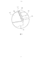
- FIG. 1 is a schematic view of an embodiment of a display device of the present invention
- FIG. 2 is a schematic view of an embodiment of a backlight module of the present invention
- FIG. 3 is a schematic view of an embodiment of an optical fiber of the present invention.
- FIG. 4 is a schematic view of an embodiment of an optical fiber light-emitting board and an optical fiber according to the present invention
- FIG. 5 is a partial enlarged view of an embodiment of a backlight module of the present invention.
- FIG. 6 is a control block diagram of an embodiment of a light intensity sensor and a processor of the present invention.
- FIG. 7 and FIG. 8 are schematic diagrams showing the combination of an embodiment of a fixing collar and an optical fiber according to the present invention.
- FIG. 9 , FIG. 10 and FIG. 11 are schematic diagrams showing a combination of an embodiment of a fixing collar and an optical fiber exiting plate according to the present invention.
- FIG. 12 and FIG. 13 are schematic diagrams showing the combination of an embodiment of a fixing collar and an optical fiber exiting plate according to the present invention.
- the word “comprising” is to be understood to include the component, but does not exclude any other component.
- “on” means located above or below the target component, and does not mean that it must be on the top based on the direction of gravity.
- FIG. 1 is a schematic diagram of an embodiment of a display device according to the present invention
- FIG. 2 is a schematic diagram of an embodiment of a backlight module of the present invention
- the backlight module 100 is disposed relative to a display panel 101 (eg, a liquid crystal display panel) to form a display device (eg, a liquid crystal display device).
- the backlight module 100 includes a plurality of optical fibers 111, an optical fiber light emitting plate 120, a light guide plate 130, a light collector 140, a back plate 150, a reflective layer 160, an optical film 170, and a plurality of fixed collars 180.
- the optical fiber 111 is connected to the concentrator 140 for transmitting light.
- the optical fiber illuminating plate 120 is disposed between the optical fiber 111 and the light guide plate 130 for providing light transmitted by the optical fiber 111 or light from the light source 122 to the light guide plate 130.
- the concentrator 140 is coupled to the optical fiber 111 for collecting external light, such as sunlight or indoor light, to provide light to the optical fiber 111.
- the light guide plate 130 can be carried on the back plate 150.
- the reflective layer 160 is formed between the back plate 150 and the light guide plate 130 for reflecting light.
- the optical film 170 is disposed on the light guide plate 130 to improve the optical effect.
- the fixing collars 180 are respectively disposed on the light-emitting ends 112 of the optical fibers 111 for fixing the optical fibers 111 on the optical fiber-emitting board 120.
- the plurality of optical fibers 111 of the present embodiment may be covered by a sheath to form a bundle of optical fibers 110 for convenient connection to the concentrator 140.
- One end of the fiber bundle 110 is connected to the concentrator 140, and the separated optical fiber 111 is connected to the optical fiber illuminating plate 120.
- FIG. 3 is a schematic diagram of an embodiment of an optical fiber of the present invention.
- the optical fiber 111 of this embodiment may have an optical fiber core 113, a cladding layer 114, and a buffer layer 115.
- a fiber core 113 can be made of, for example, quartz or PMMA for conducting light.
- the cladding 114 is made of a hard polymer (hard Made of polymer) for covering the optical fiber core 113.
- the buffer layer 115 may be made of, for example, tetrafluoroethylene for preventing the optical fiber 111 from being damaged.
- FIG. 4 is a schematic diagram of an embodiment of an optical fiber light-emitting board and an optical fiber according to the present invention
- FIG. 5 is a partially enlarged view of an embodiment of the backlight module of the present invention.
- the optical fiber light-emitting board 120 of the present embodiment is disposed between the optical fiber bundle 110 and the light guide plate 130.
- the substrate of the optical fiber light-emitting board 120 can be a circuit board, and includes a plurality of light-emitting ports 121 and a plurality of light sources 122, and the light-emitting ports 121 and The light sources 122 are disposed on the side light incident surface 133 of the light guide plate 130 for providing light to the light guide plate 130.
- the light exiting opening 121 can be a through hole for exposing the light emitting end 112 of the optical fiber 111, so that the light transmitted by the optical fiber 111 can be emitted from the light exiting opening 121 of the optical fiber light emitting plate 120 and enter the light guiding plate 130.
- the arrangement pitch of the light exit opening 121 may be less than or equal to 16 millimeters (mm) to ensure that the light can be dispersed into the light guide plate 130 to form a uniform surface light source.
- the diameter (or width) of each of the light exits 121 can be less than or equal to 2.5 mm, so that the light transmitted by the optical fiber 111 can be sufficiently emitted by the light exit opening 121.
- the light source 122 can be, for example, a light emitting diode (LED) or an organic light emitting diode (Organic Light). Emitting Diode, OLED), and located between the light exits 121.
- LED light emitting diode
- OLED Organic Light emitting diode
- the light source 122 on the fiber illuminating plate 120 can emit light to provide additional light to the light guide plate 130, ensuring that the backlight formed by the backlight module 100 has sufficient backlight. Brightness.
- the light source 122 on the optical fiber light emitting plate 120 is turned on to compensate the brightness of the backlight module 100 by light emission.
- the backlight module 100 may further include a light intensity sensor 191 for sensing light intensity.
- the light intensity sensor 191 can be disposed inside the backlight module 100, such as on the fiber exit plate 120 or in the back plate 150.
- the light source 122 is turned off without emitting light to save energy.
- the light intensity sensor 191 can transmit the sensing signal to the processor 192 of the backlight module 100. Then, the processor 192 can control the illumination of the light source 122 according to the sensing signal to compensate the brightness of the backlight module 100.
- the processor 192 can adjust the current of the light source 122 (eg, LED) according to the sensing signal to control the light intensity of the light source 122, so that the light guide plate 130 can form a surface light source with stable brightness.
- the light guide plate 130 of the present embodiment is disposed on one side of the optical fiber exit plate 120 .
- the light guide plate 130 can utilize injection molding (Injection Molding) is made of a photocurable resin, polymethyl methacrylate (PMMA) or polycarbonate (PC) for guiding the light transmitted by the optical fiber 111 to the liquid crystal display panel 101.
- injection Molding injection molding
- the light guide plate 130 has a light emitting surface 131, a light reflecting surface 132, and a side light incident surface 133.
- the light-emitting surface 131 is formed on one side of the light guide plate 130 and faces the liquid crystal display panel 101.
- the light-emitting surface 131 may have a matte surface treatment or a scattering point design to uniformize the light output of the light guide plate 130 and reduce the light unevenness (Mura). phenomenon.
- the light-emitting surface 131 may be provided with a plurality of protruding structures (not shown) to further correct the direction of the light to increase the light collecting effect and improve the front luminance.
- the protruding structures may be, for example, prismatic or semi-circular convex or concave structures.
- the light reflecting surface 132 is formed on the other side of the light guiding plate 130 opposite to the light emitting surface 131 for reflecting light to the light emitting surface 131.
- the light reflecting surface 132 of the light guide plate 130 is parallel to the light emitting surface 131.
- the light reflecting surface 132 may be provided with a light guiding structure (not shown) for reflecting the guiding light to be emitted from the light emitting surface 131.
- the light guiding structure of the light reflecting surface 132 is, for example, a continuous V-shaped structure, that is, a V-Cut structure, a matte structure, and a scattering point structure, so that the light transmitted by the guiding optical fiber 111 is sufficiently emitted from the light emitting surface 131.
- the side light incident surface 133 is formed on one side or opposite sides of the light guide plate 130, and faces the light exit opening 121 of the optical fiber exit plate 120 for allowing the light transmitted by the optical fiber 111 to enter the light guide plate 130.
- the side light incident surface 133 may have, for example, a V-shaped structure (V-Cut), an S-shaped wave structure, or a surface roughening treatment (not shown), thereby improving the incidence efficiency and optical coupling efficiency of the light.
- the concentrator 140 of the present embodiment may be disposed outside the display device (for example, outdoors or indoors) and connected to one end of the fiber bundle 110 for collecting external light such as sunlight.
- the concentrator 140 may include a susceptor 141, an optical lens 142, a photosensor 143, and a housing 144.
- the optical lens 142 and the light sensor 143 can be disposed on the base 141.
- the optical lens 142 is configured to collect external light and provide the collected light to the light incident end 116 of the fiber bundle 110.
- the light sensor 143 can be used to sense light to control the base 141 to rotate corresponding to an external light source such as the sun, thereby improving light collection efficiency.
- the cover 144 is for covering the optical lens 142 and the photosensor 143, and the cover 144 may have an ultraviolet filter layer (not shown) to filter the ultraviolet rays in the light.
- the back plate 150 is made of an opaque material, such as a plastic material, a metal material, or a combination of the above materials, for carrying the optical fiber light-emitting board 120 and the light guide plate 130.
- the backplane 150 can have corresponding through holes (not shown) to allow the optical fibers 110 to pass through.
- the reflective layer 160 (or the reflective sheet) preferably forms the surface of the light reflecting surface 132 of the light guide plate 130, and exposes only the side entrance light surface 133 for allowing light to enter and the light exit surface 131 for emitting light.
- the reflective layer 160 may be made of a high reflectivity material such as silver, aluminum, gold, chromium, copper, indium, antimony, nickel, platinum, rhodium, iridium, tin, antimony, tungsten, manganese, an alloy of any combination of the above, resistant A yellowish, heat-resistant white reflective paint or any combination of the above materials to reflect light.
- a high reflectivity material such as silver, aluminum, gold, chromium, copper, indium, antimony, nickel, platinum, rhodium, iridium, tin, antimony, tungsten, manganese, an alloy of any combination of the above, resistant A yellowish, heat-resistant white reflective paint or any combination of the above materials to reflect light.
- the optical film 170 is, for example, a diffusion sheet, a prism sheet, and a reverse prism sheet (Turning) Prism Sheet), Brightness Enhancement Film (BEF), Reflective Brightness Enhancement Film (Dual Brightness) Enhancement Film, DBEF), non-multilayer film reflective polarizer (Diffused Reflective Polarizer) Film, DRPF, or any combination thereof, is disposed on the light guide plate 130 to improve the optical effect of the light emitted from the light guide plate 130.
- BEF Brightness Enhancement Film
- DBEF Reflective Brightness Enhancement Film
- DBEF Reflective Brightness Enhancement Film
- DRPF non-multilayer film reflective polarizer
- FIG. 7 and FIG. 8 are schematic diagrams showing a combination of an embodiment of a fixing collar and an optical fiber according to the present invention.
- the retaining collar 180 of the present embodiment may be made of a plastic or metal material, preferably made of a soft material such as a silicone or rubber material to avoid scratching or damaging the optical fiber 111.
- the fixing collar 180 includes a through hole 181, a joint surface 182, and an extension portion 183.
- the optical fiber 111 can be inserted into the through hole 181 of the fixing collar 180 and expose the light emitting end 112 of the optical fiber 111.
- the bonding surface 182 is for bonding to the surface of the optical fiber luminescent panel 120 such that the fixing collar 180 can be fixed to the optical fiber luminescent panel 120.
- the through hole 181 may be formed in the extending portion 183, and the extending portion 183 may be in a cylindrical shape for supporting a portion of the optical fiber 111 adjacent to the light emitting end 112 to ensure that a portion of the optical fiber 111 adjacent to the light emitting end 112 is bent to ensure the optical fiber 111. Transmission efficiency.
- FIG. 9 , FIG. 10 and FIG. 11 are schematic diagrams showing the combination of an embodiment of a fixing collar and a fiber exiting plate.
- the optical fiber 111 and the optical fiber light emitting plate 120 are combined by the fixed collar 180, first, the optical fiber 111 is inserted into the through hole 181 of the fixing collar 180, and the light emitting end 112 of the optical fiber 111 is exposed.
- each fiber 111 can have a marking line 117 to indicate the location of the optical end 112.
- the marking line 117 of the optical fiber 111 can be aligned with the edge of the through hole 181 to accurately position the optical end 112 on the fixed collar 180.
- the optical fiber 111 and the fixed collar 180 can be fixed by, for example, an adhesive. Then, after the optical fiber 111 is combined with the fixed collar 180, the exposed light-emitting end 112 is correspondingly inserted into the light-emitting port 121 of the optical fiber light-emitting board 120, and the bonding surface 182 of the fixed collar 180 can be bonded to the optical fiber by soldering or bonding.
- the surface of the light-emitting plate 120 is fixed and positioned on the fiber-optic light-emitting plate 120.
- the bonding surface 182 of the fixing collar 180 can also be coupled to the backing plate 150, as shown in FIG. At this time, the light-emitting end 112 of the optical fiber 111 can pass through the through hole 181 of the fixed collar 180, the corresponding through hole (not shown) of the back plate 150, and the light exit opening 121 of the optical fiber exit plate 120.
- the optical fiber 111 can transmit external light (such as sunlight) collected by the concentrator 140 to the light guide plate 130. More specifically, the light collected by the concentrator 140 can be transmitted through the optical fiber 111 and emitted to the light guide plate 130 through the light exit port 121 of the optical fiber exit plate 120. Since the backlight module 100 uses external light as a side light source, the power consumption of the light source can be greatly reduced. Moreover, the external light (such as sunlight) generally has a wider color gamut, so the display device using the backlight module 100 can provide an image with real color, which greatly improves the image display quality of the display device.
- external light such as sunlight
- the light source 122 on the optical fiber exit plate 120 can emit light to compensate for the brightness, so that the backlight module 100 can provide a backlight with stable brightness.
- the collar 180 by fixing the collar 180, the light-emitting end 112 of the optical fiber 111 can be accurately positioned and fixed on the optical fiber light-emitting board 120, ensuring high optical energy utilization of the optical fiber 111.
- FIG. 12 and FIG. 13 are schematic diagrams showing another embodiment of the fixing collar and the optical fiber light-emitting board of the present invention.
- the fixing collar 180 can include a plurality of hooks 184, and the fiber exiting plate 120 further has a fixing through hole 123 for correspondingly engaging the hook 184 of the fixing collar 180. Therefore, the fixing collar 180 can be directly fixed to the optical fiber exiting plate 120 by the hook of the hook 184 and the fixing through hole 123 without using welding or pasting.
- the backlight module and the display device of the present invention can collect external light to form a backlight, thereby greatly reducing the power consumption of the light source, and improving the image color performance of the display device to improve the image display quality of the display device.
- the light source on the fiber exit plate can emit light to compensate for the brightness to ensure that the backlight of the backlight module has sufficient brightness.
- the light-emitting end of the optical fiber can be accurately positioned and fixed on the optical fiber exit plate to ensure high optical energy utilization of the optical fiber.
Landscapes
- Physics & Mathematics (AREA)
- General Physics & Mathematics (AREA)
- Optics & Photonics (AREA)
- Planar Illumination Modules (AREA)
- Optical Couplings Of Light Guides (AREA)
Abstract
Description
Claims (20)
- 一种背光模块,包括:集光器,用于收集外界光线;多条光纤,连接于所述集光器;光纤出光板,连接于所述光纤,其中所述光纤出光板包括多个出光口及多个光源,所述出光口是用于发出由所述光纤所传来的光线;以及导光板,设置于所述光纤出光板的一侧;以及光强传感器,所述光强传感器传送一感测信号至所述背光模组的处理器,所述处理器依据所述感测信号来控制所述光源的发光,所述处理器依据所述感测信号来调节所述光源的电流,以控制所述光源的发光强度,当所述光强传感器所感测的光强度高于一预设门坎值时,所述光源为关闭状态。
- 根据权利要求1所述的背光模块,其中所述光源为发光二极管或有机发光二极管。
- 根据权利要求1所述的背光模块,其中所述光源是位于所述出光口之间。
- 根据权利要求1所述的背光模块,其中当所述出光口所发出的光强度低于一预设门坎值时,所述光源为开启状态。
- 根据权利要求1所述的背光模块,还包括多个固定套环,分别套置于所述光纤的出光端上,用于固定所述光纤于所述光纤出光板上。
- 根据权利要求5所述的背光模块,其中所述固定套环包括多个卡钩,所述光纤出光板更具有固定通孔,用于对应卡合所述固定套环的卡钩。
- 一种背光模块,包括:集光器,用于收集外界光线;多条光纤,连接于所述集光器;光纤出光板,连接于所述光纤,其中所述光纤出光板包括多个出光口及多个光源,所述出光口是用于发出由所述光纤所传来的光线;以及导光板,设置于所述光纤出光板的一侧。
- 根据权利要求7所述的背光模块,其中所述光源为发光二极管或有机发光二极管。
- 根据权利要求7所述的背光模块,还包括一光强传感器,所述光强传感器传送一感测信号至所述背光模组的处理器,所述处理器依据所述感测信号来控制所述光源的发光。
- 根据权利要求9所述的背光模块,其中所述处理器依据所述感测信号来调节所述光源的电流,以控制所述光源的发光强度。
- 根据权利要求9所述的背光模块,其中当所述光强传感器所感测的光强度高于一预设门坎值时,所述光源为关闭状态。
- 根据权利要求7所述的背光模块,其中所述光源是位于所述出光口之间。
- 根据权利要求7所述的背光模块,其中当所述出光口所发出的光强度低于一预设门坎值时,所述光源为开启状态。
- 根据权利要求7所述的背光模块,还包括多个固定套环,分别套置于所述光纤的出光端上,用于固定所述光纤于所述光纤出光板上。
- 根据权利要求14所述的背光模块,其中所述固定套环包括多个卡钩,所述光纤出光板更具有固定通孔,用于对应卡合所述固定套环的卡钩。
- 一种显示装置,包括:显示面板;以及背光模块,包括:集光器,用于收集外界光线;多条光纤,连接于所述集光器;光纤出光板,连接于所述光纤,其中所述光纤出光板包括多个出光口及多个光源,所述出光口是用于发出由所述光纤所传来的光线;以及导光板,设置于所述光纤出光板的一侧。
- 根据权利要求16所述的显示装置,其中所述光源为发光二极管或有机发光二极管。
- 根据权利要求16所述的显示装置,其中所述背光模块还包括一光强传感器,所述光强传感器传送一感测信号至所述背光模组的处理器,所述处理器依据所述感测信号来控制所述光源的发光。
- 根据权利要求18所述的显示装置,其中所述处理器依据所述感测信号来调节所述光源的电流,以控制所述光源的发光强度。
- 根据权利要求18所述的显示装置,其中当所述光强传感器所感测的光强度高于一预设门坎值时,所述光源为关闭状态。
Priority Applications (2)
| Application Number | Priority Date | Filing Date | Title |
|---|---|---|---|
| US13/805,496 US9116273B2 (en) | 2012-11-02 | 2012-11-23 | Backlight module and display apparatus |
| DE112012007093.3T DE112012007093B4 (de) | 2012-11-02 | 2012-11-23 | Hintergrundlichtmodul und Anzeigevorrichtung |
Applications Claiming Priority (2)
| Application Number | Priority Date | Filing Date | Title |
|---|---|---|---|
| CN201210431938.X | 2012-11-02 | ||
| CN201210431938XA CN102966910A (zh) | 2012-11-02 | 2012-11-02 | 背光模块及显示装置 |
Publications (1)
| Publication Number | Publication Date |
|---|---|
| WO2014067196A1 true WO2014067196A1 (zh) | 2014-05-08 |
Family
ID=47797230
Family Applications (1)
| Application Number | Title | Priority Date | Filing Date |
|---|---|---|---|
| PCT/CN2012/085144 Ceased WO2014067196A1 (zh) | 2012-11-02 | 2012-11-23 | 背光模块及显示装置 |
Country Status (3)
| Country | Link |
|---|---|
| CN (1) | CN102966910A (zh) |
| DE (1) | DE112012007093B4 (zh) |
| WO (1) | WO2014067196A1 (zh) |
Cited By (1)
| Publication number | Priority date | Publication date | Assignee | Title |
|---|---|---|---|---|
| CN108108718A (zh) * | 2018-01-05 | 2018-06-01 | 敦捷光电股份有限公司 | 屏内光学指纹辨识的薄膜晶体管面板 |
Families Citing this family (13)
| Publication number | Priority date | Publication date | Assignee | Title |
|---|---|---|---|---|
| CN102966911B (zh) | 2012-11-02 | 2014-11-26 | 深圳市华星光电技术有限公司 | 背光模块及显示装置 |
| CN103206663B (zh) * | 2013-04-19 | 2015-05-06 | 深圳市华星光电技术有限公司 | 背光模组 |
| CN104279516A (zh) * | 2013-07-02 | 2015-01-14 | 华为终端有限公司 | 集光装置及显示装置 |
| CN104100924B (zh) | 2013-11-26 | 2016-04-13 | 深圳市华星光电技术有限公司 | 背光模组及使用该背光模组的背光系统 |
| CN104566181B (zh) * | 2015-01-15 | 2017-06-06 | 华南理工大学 | 一种无导光板自然光平板灯 |
| CN104776355B (zh) * | 2015-04-01 | 2017-10-27 | 深圳市华星光电技术有限公司 | 液晶显示装置及其背光模组 |
| FR3050541B1 (fr) * | 2016-04-26 | 2019-07-12 | Valeo Comfort And Driving Assistance | Afficheur |
| CN106502000A (zh) * | 2016-12-02 | 2017-03-15 | 武汉华星光电技术有限公司 | 背光模组及显示面板 |
| CN106990535A (zh) * | 2017-04-17 | 2017-07-28 | 京东方科技集团股份有限公司 | 背光系统、显示装置及汽车 |
| CN107192378B (zh) * | 2017-06-23 | 2019-09-24 | 西安工业大学 | 一种用于高速摄影测量系统的光源面装置 |
| CN108227306B (zh) * | 2018-01-30 | 2021-01-26 | 京东方科技集团股份有限公司 | 一种背光模组及发光方法、显示装置 |
| CN111077691A (zh) * | 2018-10-18 | 2020-04-28 | 徐瑞宏 | 一种lcd显示装置及lcd显示装置的引光方法 |
| CN116246549A (zh) * | 2023-02-24 | 2023-06-09 | 深圳市壹显科技有限公司 | 一种户外显示器增亮方法、装置、存储介质及终端设备 |
Citations (5)
| Publication number | Priority date | Publication date | Assignee | Title |
|---|---|---|---|---|
| JP2000231816A (ja) * | 1999-02-12 | 2000-08-22 | Sanyo Electric Co Ltd | 光源装置およびバックライト装置 |
| JP2005091494A (ja) * | 2003-09-12 | 2005-04-07 | Seiko Epson Corp | 電気光学装置、および電子機器 |
| CN101782698A (zh) * | 2009-01-20 | 2010-07-21 | 欧睿控股股份有限公司 | 环境光辅助的液晶显示器及照明装置 |
| CN102073166A (zh) * | 2010-12-20 | 2011-05-25 | 北京同方瑞博数字技术有限公司 | 一种利用太阳光线的节能液晶电视 |
| CN102193247A (zh) * | 2011-05-19 | 2011-09-21 | 上海桓伟触摸科技有限公司 | 一种户外液晶显示器 |
Family Cites Families (6)
| Publication number | Priority date | Publication date | Assignee | Title |
|---|---|---|---|---|
| US7413328B2 (en) | 2004-12-30 | 2008-08-19 | Honeywell International Inc. | Remotely coupled hybrid HUD backlight |
| US7213955B1 (en) | 2005-10-26 | 2007-05-08 | Research In Motion Limited | System and method for providing ambient light to a display in an electronic device |
| CN201041322Y (zh) * | 2007-05-23 | 2008-03-26 | 谢秋菊 | 用于发光二极管的导光装置 |
| CN201081152Y (zh) * | 2007-08-04 | 2008-07-02 | 鹤山丽得电子实业有限公司 | 一种光纤背光源 |
| KR101052890B1 (ko) | 2011-03-24 | 2011-07-29 | 주식회사 건기 | 확산 굴절과 확산 반사 기능을 겸비한 하이브리드 태양광 확산체가 구비되는 태양광 조명 장치 |
| CN102494297A (zh) * | 2011-12-07 | 2012-06-13 | 南京中电熊猫液晶显示科技有限公司 | 一种利用环境光的背光源模组及其液晶显示装置 |
-
2012
- 2012-11-02 CN CN201210431938XA patent/CN102966910A/zh active Pending
- 2012-11-23 WO PCT/CN2012/085144 patent/WO2014067196A1/zh not_active Ceased
- 2012-11-23 DE DE112012007093.3T patent/DE112012007093B4/de not_active Expired - Fee Related
Patent Citations (5)
| Publication number | Priority date | Publication date | Assignee | Title |
|---|---|---|---|---|
| JP2000231816A (ja) * | 1999-02-12 | 2000-08-22 | Sanyo Electric Co Ltd | 光源装置およびバックライト装置 |
| JP2005091494A (ja) * | 2003-09-12 | 2005-04-07 | Seiko Epson Corp | 電気光学装置、および電子機器 |
| CN101782698A (zh) * | 2009-01-20 | 2010-07-21 | 欧睿控股股份有限公司 | 环境光辅助的液晶显示器及照明装置 |
| CN102073166A (zh) * | 2010-12-20 | 2011-05-25 | 北京同方瑞博数字技术有限公司 | 一种利用太阳光线的节能液晶电视 |
| CN102193247A (zh) * | 2011-05-19 | 2011-09-21 | 上海桓伟触摸科技有限公司 | 一种户外液晶显示器 |
Cited By (1)
| Publication number | Priority date | Publication date | Assignee | Title |
|---|---|---|---|---|
| CN108108718A (zh) * | 2018-01-05 | 2018-06-01 | 敦捷光电股份有限公司 | 屏内光学指纹辨识的薄膜晶体管面板 |
Also Published As
| Publication number | Publication date |
|---|---|
| CN102966910A (zh) | 2013-03-13 |
| DE112012007093B4 (de) | 2021-12-09 |
| DE112012007093T5 (de) | 2015-07-23 |
Similar Documents
| Publication | Publication Date | Title |
|---|---|---|
| WO2014067196A1 (zh) | 背光模块及显示装置 | |
| WO2014067195A1 (zh) | 背光模块及显示装置 | |
| WO2014067191A1 (zh) | 背光模块及显示装置 | |
| WO2014015547A1 (zh) | 背光模块及显示装置 | |
| WO2014067193A1 (zh) | 背光模块及显示装置 | |
| WO2014012277A1 (zh) | 背光模块及显示装置 | |
| CN101324725B (zh) | 液晶显示设备与背光装置 | |
| CN202835065U (zh) | 一种背光模组及显示装置 | |
| US9116273B2 (en) | Backlight module and display apparatus | |
| CN101725914A (zh) | 侧光式发光二极管背光源及液晶显示器 | |
| WO2014067192A1 (zh) | 背光模块及显示装置 | |
| WO2013143158A1 (zh) | 发光二极管灯条构造 | |
| WO2013170509A1 (zh) | 散热铝挤结构及相应的背光模块 | |
| CN104832837A (zh) | 背光模组及显示器 | |
| WO2020124891A1 (zh) | 背光模组及显示装置 | |
| WO2013174032A1 (zh) | 背光模组及液晶显示装置 | |
| CN202361206U (zh) | 背光模组以及液晶显示装置 | |
| CN101666459A (zh) | 背光源膜材与led背光源 | |
| US8860910B2 (en) | Backlight module and display apparatus | |
| WO2014067189A1 (zh) | 背光模块及显示装置 | |
| WO2013134971A1 (zh) | 背光模块以及液晶显示装置 | |
| WO2014067194A1 (zh) | 背光模块及显示装置 | |
| WO2012129824A1 (zh) | 背光模块及显示装置 | |
| WO2020107897A1 (zh) | 一种背光模组及其显示装置 | |
| WO2013155699A1 (zh) | 背光模块以及液晶显示装置 |
Legal Events
| Date | Code | Title | Description |
|---|---|---|---|
| WWE | Wipo information: entry into national phase |
Ref document number: 13805496 Country of ref document: US |
|
| 121 | Ep: the epo has been informed by wipo that ep was designated in this application |
Ref document number: 12887552 Country of ref document: EP Kind code of ref document: A1 |
|
| WWE | Wipo information: entry into national phase |
Ref document number: 112012007093 Country of ref document: DE Ref document number: 1120120070933 Country of ref document: DE |
|
| 122 | Ep: pct application non-entry in european phase |
Ref document number: 12887552 Country of ref document: EP Kind code of ref document: A1 |