WO2014065053A1 - 撮像装置及び画像生成方法 - Google Patents
撮像装置及び画像生成方法 Download PDFInfo
- Publication number
- WO2014065053A1 WO2014065053A1 PCT/JP2013/075622 JP2013075622W WO2014065053A1 WO 2014065053 A1 WO2014065053 A1 WO 2014065053A1 JP 2013075622 W JP2013075622 W JP 2013075622W WO 2014065053 A1 WO2014065053 A1 WO 2014065053A1
- Authority
- WO
- WIPO (PCT)
- Prior art keywords
- normal image
- image
- color filter
- correction information
- spectrum
- Prior art date
- Legal status (The legal status is an assumption and is not a legal conclusion. Google has not performed a legal analysis and makes no representation as to the accuracy of the status listed.)
- Ceased
Links
Images


Classifications
-
- H—ELECTRICITY
- H04—ELECTRIC COMMUNICATION TECHNIQUE
- H04N—PICTORIAL COMMUNICATION, e.g. TELEVISION
- H04N23/00—Cameras or camera modules comprising electronic image sensors; Control thereof
- H04N23/10—Cameras or camera modules comprising electronic image sensors; Control thereof for generating image signals from different wavelengths
- H04N23/11—Cameras or camera modules comprising electronic image sensors; Control thereof for generating image signals from different wavelengths for generating image signals from visible and infrared light wavelengths
-
- H—ELECTRICITY
- H04—ELECTRIC COMMUNICATION TECHNIQUE
- H04N—PICTORIAL COMMUNICATION, e.g. TELEVISION
- H04N23/00—Cameras or camera modules comprising electronic image sensors; Control thereof
- H04N23/10—Cameras or camera modules comprising electronic image sensors; Control thereof for generating image signals from different wavelengths
- H04N23/12—Cameras or camera modules comprising electronic image sensors; Control thereof for generating image signals from different wavelengths with one sensor only
-
- H—ELECTRICITY
- H04—ELECTRIC COMMUNICATION TECHNIQUE
- H04N—PICTORIAL COMMUNICATION, e.g. TELEVISION
- H04N23/00—Cameras or camera modules comprising electronic image sensors; Control thereof
- H04N23/80—Camera processing pipelines; Components thereof
- H04N23/84—Camera processing pipelines; Components thereof for processing colour signals
- H04N23/88—Camera processing pipelines; Components thereof for processing colour signals for colour balance, e.g. white-balance circuits or colour temperature control
-
- H—ELECTRICITY
- H04—ELECTRIC COMMUNICATION TECHNIQUE
- H04N—PICTORIAL COMMUNICATION, e.g. TELEVISION
- H04N23/00—Cameras or camera modules comprising electronic image sensors; Control thereof
- H04N23/95—Computational photography systems, e.g. light-field imaging systems
-
- H—ELECTRICITY
- H04—ELECTRIC COMMUNICATION TECHNIQUE
- H04N—PICTORIAL COMMUNICATION, e.g. TELEVISION
- H04N25/00—Circuitry of solid-state image sensors [SSIS]; Control thereof
- H04N25/10—Circuitry of solid-state image sensors [SSIS]; Control thereof for transforming different wavelengths into image signals
- H04N25/11—Arrangement of colour filter arrays [CFA]; Filter mosaics
- H04N25/13—Arrangement of colour filter arrays [CFA]; Filter mosaics characterised by the spectral characteristics of the filter elements
- H04N25/131—Arrangement of colour filter arrays [CFA]; Filter mosaics characterised by the spectral characteristics of the filter elements including elements passing infrared wavelengths
-
- H—ELECTRICITY
- H04—ELECTRIC COMMUNICATION TECHNIQUE
- H04N—PICTORIAL COMMUNICATION, e.g. TELEVISION
- H04N25/00—Circuitry of solid-state image sensors [SSIS]; Control thereof
- H04N25/10—Circuitry of solid-state image sensors [SSIS]; Control thereof for transforming different wavelengths into image signals
- H04N25/11—Arrangement of colour filter arrays [CFA]; Filter mosaics
- H04N25/13—Arrangement of colour filter arrays [CFA]; Filter mosaics characterised by the spectral characteristics of the filter elements
- H04N25/135—Arrangement of colour filter arrays [CFA]; Filter mosaics characterised by the spectral characteristics of the filter elements based on four or more different wavelength filter elements
-
- H—ELECTRICITY
- H04—ELECTRIC COMMUNICATION TECHNIQUE
- H04N—PICTORIAL COMMUNICATION, e.g. TELEVISION
- H04N25/00—Circuitry of solid-state image sensors [SSIS]; Control thereof
- H04N25/70—SSIS architectures; Circuits associated therewith
- H04N25/703—SSIS architectures incorporating pixels for producing signals other than image signals
-
- H—ELECTRICITY
- H04—ELECTRIC COMMUNICATION TECHNIQUE
- H04N—PICTORIAL COMMUNICATION, e.g. TELEVISION
- H04N2209/00—Details of colour television systems
- H04N2209/04—Picture signal generators
- H04N2209/041—Picture signal generators using solid-state devices
- H04N2209/042—Picture signal generators using solid-state devices having a single pick-up sensor
- H04N2209/047—Picture signal generators using solid-state devices having a single pick-up sensor using multispectral pick-up elements
Definitions
- the present invention relates to an imaging device, an image generation method, and the like.
- an imaging device In order to capture a full-color image, an imaging device is known in which three types of color filters of R (red: Red), G (green: Green), and B (blue: Blue) are provided in the imaging device.
- R red: Red
- G green
- B blue
- the conventional imaging device since the number of bands of the color filter is small, the sample density of pixels corresponding to each band is relatively high, and it is possible to generate a normal image with high accuracy.
- Patent Document 3 correction information that improves color reproducibility is generated from information obtained from a spectrum measurement sensor using an imaging device in which a spectrum measurement sensor is installed separately from the image sensor, and the image sensor A method for correcting a normal image (RGB image) obtained from the above has also been proposed.
- an imaging device an image generation method, and the like that can correct a normal image using estimated spectrum information while suppressing deterioration in image quality.
- One aspect of the present invention is a color filter array in which three or more bands of normal image generation color filters and correction information generation color filters having spectral sensitivity characteristics different from those of the normal image generation color filters are arranged in an array.
- a normal image generation unit that performs normal image generation processing in which pixel values of missing pixels are interpolated by performing interpolation processing of pixel values obtained by using the normal image generation color filter;
- a spectrum estimation unit that performs a spectrum estimation process based on at least a pixel value obtained using the correction information generation color filter, and a pixel of the normal image based on a spectrum estimation value obtained by the spectrum estimation unit
- a correction information generating unit that generates correction information for correcting the value, and correcting the normal image based on the correction information, thereby correcting It relates to an imaging apparatus including, a corrected image generation unit that generates an image.
- the normal image generation unit performs interpolation processing of pixel values obtained using the normal image generation color filter, and generates a normal image in which pixel values of missing pixels are interpolated.
- the spectrum estimation unit performs spectrum estimation processing based on at least a pixel value obtained using the correction information generation color filter among the normal image generation color filter and the correction information generation color filter.
- the correction information generation unit generates correction information for correcting the pixel value of the normal image based on the spectrum estimation value. Further, the corrected image generation unit performs a normal image correction process based on the correction information to generate a corrected image.
- the correction information generation unit may perform the spectrum estimation processing on the plurality of pixel values of the normal image based on data of one spectrum estimation value obtained from one pixel value. Correction information may be generated.
- attention area detection that detects an attention area, which is an attention area, in the normal image including a subject image having information in a specific wavelength band based on the spectrum estimation value data.
- a display mode setting unit that performs a display mode setting process on the detected region of interest.
- the normal image generation color filter includes an R color filter, a G color filter, and a B color filter
- the correction information generation color filter includes:
- the color filter array may be arranged at a lower sample density than any of the R color filter, the G color filter, and the B color filter.
- the G color filter of the normal image generation color filters may include an odd-numbered odd-numbered column and an even-numbered even-numbered column or an even-numbered odd-numbered row in the color filter array. It may be arranged in columns and odd columns in even rows.
- the generation of a special wavelength interpolation image for generating a special wavelength interpolation image used for generating the correction information based on a pixel value obtained by using the correction information generation color filter performs interpolation processing of pixel values obtained using the correction information generation color filter as the generation processing, and the special wavelength interpolated image generation unit interpolates pixel values of missing pixels.
- a wavelength interpolation image may be generated, and the spectrum estimation unit may perform the spectrum estimation process based on the special wavelength interpolation image.
- the special wavelength interpolation image generation unit generates the special wavelength interpolation image having a lower resolution than the normal image generated by the normal image generation unit
- the spectrum estimation unit includes: Based on at least the pixel value of the special wavelength interpolated image, the spectrum estimation process is performed at the resolution of the special wavelength interpolated image, and the correction information generation unit is configured to obtain one spectrum estimated value obtained as a result of the spectrum estimation process. Based on the data, the correction information for the plurality of pixel values of the normal image is generated, and the correction image generation unit performs the correction process at the resolution of the normal image using the generated correction information. Also good.
- the spectrum estimation unit extracts a light source color pixel representing a light source color from the normal image, estimates a light source spectrum of the extracted light source color pixel, and calculates a light source spectrum estimation value. Then, the correction information generation unit may estimate the light source by comparing the data of the light source spectrum estimation value with the light source spectrum data stored in advance.
- the corrected image generation unit may perform the correction process for correcting white balance on the normal image based on the estimated light source.
- the correction information generation unit generates the correction information for each of a plurality of regions set in the normal image
- the correction image generation unit includes the correction information generation unit.
- the correction processing for the normal image may be performed using the correction information for each region in the normal image generated by the above.
- the correction information generation unit performs a comparison process between the spectrum estimation value data estimated by the spectrum estimation unit and the spectrum data to be detected stored in advance, A specific spectrum region having a specific spectrum may be detected based on the result of the comparison process, and the correction information may be generated based on the detected detection result of the specific spectrum region.
- the spectrum estimation unit extracts a light source spectrum data measurement pixel representing a light source color from the special wavelength interpolation image, and estimates a light source spectrum of the extracted light source spectrum data measurement pixel. Then, the light source spectrum estimated value is obtained, and the corrected image generation unit may perform a process of correcting white balance on the normal image based on the light source spectrum estimated value.
- the spectrum estimation unit performs spectrum estimation on the special wavelength interpolation image based on light source spectrum data of white light
- the correction information generation unit is The light source may be estimated by comparing the spectrum estimation value data with light source spectrum data stored in advance.
- the spectrum estimation unit may not read out the pixel value obtained by using the normal image generation color filter when reading out the pixel value from the image sensor, and may generate the correction information generation color. It is also possible to perform decimation readout for reading out pixel values obtained using a filter, and perform the spectrum estimation processing using the pixel values obtained by decimation.
- the normal image generation color filter and the correction information generation color filter of the image sensor may be an infrared filter having a peak wavelength in an infrared light wavelength region.
- the wavelength band of the infrared light may be a wavelength band of 790 to 820 nanometers, or 905 to 970 nanometers.
- a normal image generating color filter having three or more bands and a correction information generating color filter having spectral sensitivity characteristics different from those of the normal image generating color filter are arranged in an array.
- a normal image that performs normal image generation processing in which pixel values of missing pixels are interpolated by performing interpolation processing of pixel values obtained using the image sensor having a color filter array and the normal image generation color filter A generation unit, a spectrum estimation unit that performs spectrum estimation processing based on at least the pixel value obtained using the correction information generation color filter, and the normal estimation based on a spectrum estimation value obtained from the spectrum estimation unit
- a correction information generation unit that generates correction information for correcting pixel values of the image, and performs correction processing of the normal image based on the correction information.
- the spectrum estimation unit obtains a region of interest as a region of interest from the spectrum estimation unit.
- the present invention relates to an imaging apparatus including an attention area detection unit that detects based on value data and a display mode setting unit that performs a display mode setting process on the detected attention area.
- normal image generation processing in which pixel values of missing pixels are interpolated is performed by performing interpolation processing of pixel values obtained using a color filter for normal image generation of three or more bands. And performing at least a spectrum estimation process based on a pixel value obtained using a correction information generation color filter having a spectral sensitivity characteristic different from that of the normal image generation color filter, and as a result of the spectrum estimation process.
- the present invention relates to an image generation method for generating correction information for correcting pixel values of the normal image based on the obtained spectrum estimation value, performing correction processing for the normal image based on the correction information, and generating a correction image. To do.
- normal image generation processing in which pixel values of missing pixels are interpolated is performed by performing interpolation processing of pixel values obtained using a color filter for normal image generation of three or more bands. And performing a spectrum estimation process based on a pixel value obtained using a correction information generation color filter having a spectral sensitivity characteristic different from that of the normal image generation color filter to obtain information in a specific wavelength band.
- a region of interest that is a region of interest is detected based on spectrum estimation value data obtained as a result of the spectrum estimation process, and a display mode is displayed for the detected region of interest
- the present invention relates to an image generation method for performing setting processing.
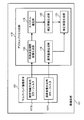
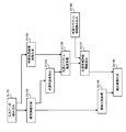
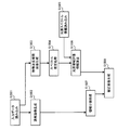
- FIG. 1 is a configuration example of a digital process circuit included in the imaging apparatus according to the first embodiment.
- FIG. 2 is a configuration example of the entire imaging apparatus according to the first embodiment.
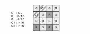
- FIG. 3 shows an example of CFA when a color filter for generating correction information of two bands is used.
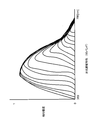
- FIG. 4 shows an example of spectral sensitivity characteristics of the color filter.
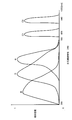
- FIG. 5 is an example of spectral sensitivity characteristics of the color filter used in the first embodiment.
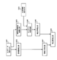
- FIG. 6 is a flowchart for explaining the flow of processing of the first embodiment.
- FIG. 7 shows an example of CFA when an 8-band correction information generating color filter is used.
- FIG. 8 is an explanatory diagram of a region in a normal image corresponding to one correction information.
- FIG. 9 is a configuration example of a digital process circuit used in a modification of the first embodiment.
- FIG. 10 is a flowchart for explaining the flow of processing in a modification of the first embodiment.
- FIG. 11 is a comparative example of spectrum estimation value data and detection target spectrum data.
- FIG. 12 shows an example of a two-dimensional evaluation value map.
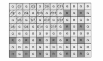
- FIG. 13 shows an example of CFA when a 16-band correction information generating color filter is used.
- FIG. 14 shows an example of spectral sensitivity characteristics of a color filter for 16-band correction information generation.
- FIG. 15 is a flowchart for explaining the flow of processing of the second embodiment.
- FIG. 16 is an explanatory diagram of thinning readout.
- FIG. 17 is an explanatory diagram of light source color determination processing.
- FIG. 16 is an explanatory diagram of thinning readout.
- FIG. 17 is an explanatory diagram of light source color determination processing.
- FIG. 16 is an explanatory diagram of thinning read
- FIG. 18 shows an example of CFA when a 16-band correction information generation color filter is used and light source estimation accuracy is emphasized.
- FIG. 19 is a flowchart for explaining the flow of processing according to a modification of the second embodiment.
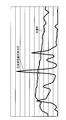
- FIG. 20 shows an example of light source spectrum data.
- an imaging apparatus In order to capture a full-color image, an imaging apparatus is known in which three types of color filters of R (red: Red), G (green: Green), and B (blue: Blue) are provided in an imaging element.
- R red: Red
- G green
- B blue
- the number of bands of the color filter is small, the sample density of pixels corresponding to each band is relatively high, and it is possible to generate a normal image with high accuracy.
- Patent Document 3 using an imaging apparatus in which a spectrum measurement sensor is installed separately from the image sensor, correction information that improves color reproducibility is generated by information obtained from the spectrum measurement sensor.
- a method for correcting a normal image (RGB image) obtained from an image sensor has also been proposed.
- Patent Document 3 has problems with respect to the size and cost of the apparatus.
- image quality degradation is minimized by using a single-plate multiband imaging device having four or more different spectral sensitivity characteristics. It is possible to correct the normal image using the estimated spectral information while limiting to the limit.
- the imaging devices of the following first and second embodiments can be effectively used for color correction of a normal image, light source detection of a subject, subject detection, and the like.
- the spectral information of the subject is estimated, and the processing result based on the spectral information is used for correcting the normal image.
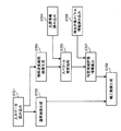
- FIG. 1 is a system configuration diagram of the first embodiment.
- the image pickup apparatus 101 includes a multiband image pickup element 107 including a color filter having four or more different spectral sensitivity characteristics for photoelectrically converting a subject image, and a digital process circuit 110 for performing various digital processes.
- the digital process circuit 110 includes a normal image generation unit 118 and a special wavelength interpolation image generation unit as functional units for generating a corrected image based on the spectrum estimation result that is a feature of the present embodiment as shown in FIG. 130, a spectrum estimation unit 119, a correction information generation unit 120, and a correction image generation unit 121 are provided.
- the multiband imaging device 107 includes a normal image generation color filter 1071 and a correction information generation color filter 1072.
- the imaging apparatus 101 is not limited to the configuration shown in FIG. 1, and various modifications such as omitting some of these components or adding other components are possible.
- the multiband image sensor 107 is connected to a normal image generation unit 118 and a special wavelength interpolation image generation unit 130.
- the normal image generation unit 118 is connected to the corrected image generation unit 121, and the special wavelength interpolation image generation unit 130 is connected to the spectrum estimation unit 119.
- the spectrum estimation unit 119 is connected to the correction information generation unit 120, and the correction information generation unit 120 is connected to the correction image generation unit 121.
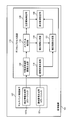
- FIG. 2 shows an example of the entire image of the imaging apparatus having the configuration of FIG.
- the imaging apparatus 101 includes an imaging lens system 102 composed of various lenses (imaging lenses), a lens driving mechanism 103 for driving expansion and contraction of the lens system 102 and a zoom lens and a focus lens in the lens system, and a lens.
- a lens driver 104 for controlling the drive mechanism 103, an exposure control mechanism 105 for controlling the aperture and shutter of the lens system 102, an exposure control driver 106 for controlling the exposure control mechanism 105, and a subject image.
- a multi-band image sensor 107 incorporating a color filter having four or more different spectral sensitivity characteristics for photoelectric conversion, an image sensor driver 108 for driving the image sensor, an analog amplifier, an A / D converter, and the like Including pre-processing circuit 109, color signal processing and compression / decompression processing for recording image generation, A digital process circuit 110 for performing various other digital processing, a card interface 111 that is an interface with a memory card that is an external recording medium, an LCD (Liquid Crystal Display) image display system 112, a release switch and setting buttons An operation switch system 113 including various switches, an operation display system 114 for displaying an operation state and a mode state, a non-volatile memory 115 for setting various setting information and the like, and overall control of each unit.
- a system controller 116 is configured to control of each unit.
- the normal image generation unit 118 generates a normal image by performing a demosaicing process on each pixel of the RAW data obtained using the normal image generation color filter 1071 of the multiband image sensor 107.
- the special wavelength interpolation image generation unit 130 generates a special wavelength interpolation image based on pixel values obtained using the correction information generation color filter 1072 of the multiband image sensor 107.
- the spectrum estimation unit 119 performs spectrum estimation using the special wavelength interpolation image generated by the special wavelength interpolation image generation unit 130 and the light source information stored in the spectrum estimation unit 119 in advance.
- the correction information generation unit 120 generates correction information for the RGB image (normal image) using the spectrum information obtained from the spectrum estimation unit 119.
- the correction image generation unit 121 generates a correction image using the RGB normal image generated by the normal image generation unit 118 and the correction information obtained by the correction information generation unit 120.
- the signal processing unit 123 performs various digital processing such as color signal generation processing, and then generates a final processing result image.
- the functions of the normal image generation unit 118, the special wavelength interpolation image generation unit 130, the spectrum estimation unit 119, the correction information generation unit 120, and the correction image generation unit 121 are various processors (such as a CPU), ASIC (gate). It can be realized by hardware such as an array) or a program.
- the system controller 116 performs all the control, and controls the exposure of the multiband image pickup element 107 by the lens driver 104, the exposure control driver 106, and the image pickup element driver 108 (exposure). (Electric storage) and signals are read out, A / D converted through the pre-process circuit 109 and then taken into the digital process circuit 110, and after various signal processing in the digital process circuit 110, the card interface 111 is used. Are recorded on the memory card 117.
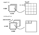
- a color filter array having five types of spectral sensitivity characteristics (hereinafter referred to as CFA: Color Filter). Array) is shown in FIG.
- CFA Color Filter
- the pixels of the special wavelengths C1 and C2 are arranged at the positions of the R pixel and the B pixel in the Bayer array so that the G pixel has the same sample density as the Bayer array.
- an actual image sensor is configured by repeatedly arranging the CFA of FIG.
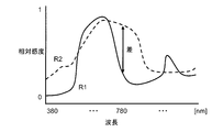
- the color filter used in the above-mentioned Patent Document 2 is a color filter having spectral sensitivity characteristics as shown in the graph of FIG. In Patent Document 2, etc., pixel values obtained using C1 and C2 are also used to generate a normal image. Therefore, in order to compensate for the range where the relative sensitivity of B and G is lowered by C1 and C2, the bands of C1 and C2 for special wavelengths overlap with the bands of B and G.
- the color filter used in the present embodiment is a color filter having spectral sensitivity characteristics as shown in the graph of FIG.
- pixel values obtained from C1 and C2 are used to generate correction information. Therefore, it is desirable that the special wavelength C1 and C2 bands are easily distinguishable from any of R, G, and B.
- C1 and C2 are any of the R, G, and B bands. There is no duplication.
- RAW data input data obtained from the multiband image sensor 107 is read (S401), demosaicing processing is performed on RGB pixel data, and a normal image (RGB image) is generated (S402). .
- demosaicing processing is also performed on the special wavelength pixel data to generate a special wavelength interpolation image (S403).
- the light source information stored in the spectrum estimation unit 119 is read in advance (S404), and the spectrum estimation process is performed using the special wavelength interpolation image generated in step S403 and the light source information read in step S404. This is performed (S405).
- correction information for the normal image is generated using the spectrum information estimated in step S405 (S406).
- a correction image is generated by performing correction processing on the normal image. (S408).
- Patent Document 4 discloses a technique for performing interpolation in consideration of peripheral pixel information and edge direction with respect to a target pixel to be interpolated.
- step S402 and step S403 only the information on the RGB pixels is used when generating the RGB normal image, and only the information on the special wavelength pixels is used when generating the interpolated image of the special wavelength. Interpolation processing is performed using.
- ⁇ is the wavelength
- f (b, ⁇ ) is the spectral sensitivity characteristic of the color filter in band b
- s ( ⁇ ) is the spectral sensitivity characteristic of the camera
- e ( ⁇ ) is the spectral radiation characteristic of the light source
- n (b) Represents imaging noise in band b.
- b is a serial number for identifying a band, and is an integer value satisfying 1 ⁇ b ⁇ 5 in the CFA of FIG.
- the following formula (2) obtained by discretizing the formula (1) in the wavelength direction is used.
- G (x, y) is B rows and 1 column corresponding to the pixel value g (x, y, b) at the position (x, y). Is a matrix.
- T (x, y) is a D ⁇ 1 matrix corresponding to t (x, y, ⁇ )
- F is a B ⁇ D matrix corresponding to f (b, ⁇ ).
- S is a diagonal matrix of D rows and D columns, and the diagonal elements correspond to s ( ⁇ ).
- E is also a diagonal matrix of D rows and D columns, and the diagonal element corresponds to e ( ⁇ ).
- N is a B ⁇ 1 matrix corresponding to n (b).
- Expression (2) since the expressions related to a plurality of bands are aggregated using a matrix, the variable b representing the number of bands is not explicitly described. In addition, the integration with respect to the wavelength ⁇ is replaced with a matrix product.
- Wiener estimation is used as a method for estimating the spectral reflectance of the subject.
- Wiener estimation is a method of estimating an original signal from a signal on which noise is superimposed, and an estimated value of spectral reflectance (the left side of equation (3)) can be obtained by the following equation (3).
- R ss is a matrix of D rows and D columns, and represents a covariance matrix of the spectral reflectance of the target subject.
- Rnn is a matrix of B rows and B columns, and represents a covariance matrix of camera noise used for imaging.
- () t represents a transposed matrix
- () -1 represents an inverse matrix.
- the spectrum estimation method is not limited to this.
- spectrum estimation may be performed for each pixel region in the state of RAW data obtained from the multiband image sensor 107.
- As a method of performing spectrum estimation directly from RAW data it is possible to apply a method of performing spectrum estimation by linear combination of basis data using basis data for each region obtained in advance by principal component analysis on learning data. It is.
- By performing spectrum estimation directly from the RAW data it is possible to avoid the accuracy of the demosaicing process from affecting the spectrum estimation.
- there are many spectrum estimation methods for processing demosaiced data and it is possible to apply various spectrum estimation methods by generating interpolated images of special wavelengths.
- the bands used for spectrum estimation need not be all bands.
- the spectrum may be estimated only from information on special bands.
- the spectrum estimation is also performed using normal RGB images.
- the light source information used for spectrum estimation uses the light source information previously held in the spectrum estimation unit 119, but it is also possible to use information obtained from the light source detection sensor 124 shown in FIG. By using information from the light source detection sensor, it is possible to deal with a light source that does not hold information in advance.
- step S406 the correction information generation process in step S406 will be described.
- a matrix associated with each pixel (p, q) of the estimated spectrum data is generated, and the matrix data for each pixel (p, q) A set with pixel position data relating to the pixel (p, q) is output.
- spectrum data having M1 elements in the vertical direction, M2 elements in the horizontal direction, and D elements in the wavelength direction as shown in FIG. 8 is received, and the spectrum data is obtained from the received spectrum data by equation (4).
- a matrix for each pixel (p, q) is generated for all pixel positions, and a set of the generated matrix data for each pixel and pixel position data for the pixel (p, q) is output.
- the number of pixels of the spectrum data is the same as the number of elements of the spectrum data. That is, p is a natural number that satisfies 0 ⁇ p ⁇ M1, and q is a natural number that satisfies 0 ⁇ q ⁇ M2.
- a (p, q) means a matrix defined for each pixel (p, q) of the spectrum data.
- K means a matrix of D rows and M columns in which M pieces of spectrum data are arranged as column vectors.
- H is represented by an expression (5) between the original spectrum information T (x, y), the corresponding image data G (x, y), and a three-dimensional column vector N indicating noise included in the image data.
- This means a matrix of 3 rows and D columns that defines the input / output relationship, and is specifically represented by Expression (6).
- C means a noise covariance matrix.
- correction information is generated for each region, but naturally, one correction information may be generated for the entire image.
- one correction information may be generated for the entire image.
- simple processing can be performed.
- one piece of correction information is generated for the entire image, it can be expressed by the following equation (7), for example.
- Aw is a correction matrix for the entire image
- M is the number of spectrum data, that is, M1 ⁇ M2.
- step S407 Next, the area dividing process in step S407 will be described.
- area division processing is performed for the normal image generated in step S402 to correspond to the correction matrix generated in step S406, and one area of the normal image corresponds to one correction matrix. Like that.
- the special wavelength interpolated image in step S403 is generated in a size of N1 in the vertical direction and N2 in the horizontal direction, or the processing for upsampling the spectrum data to the sizes of N1 and N2 during the correction information generation processing in step S406.
- the area dividing process in step S407 is not necessary.
- the region division processing in step S407 is not necessary.
- step S408 a correction image is generated using the correction matrix generated in step S406 with respect to the normal image divided in step S407.
- a normal image and a correction matrix are used to estimate a spectrum for each pixel, and the estimated spectral data is converted into RGB data, thereby generating a corrected image.
- a matrix to be converted into RGB can be created by the spectrum estimation means, and a normal image can be generated.
- a matrix to be converted into RGB can be created by the spectrum estimation means, and a normal image can be generated.
- x t , y t , and v t defined by the color matching function are used for f (b, ⁇ ), respectively.
- Expression (12) is obtained by converting the left side of Expression (8) into a continuous form in the wavelength direction.
- FIG. 9 shows a system configuration example of this modification.
- the system configuration of this modification is based on the configuration of the first embodiment, but the contents of processing performed in the digital process circuit 110 are different.
- the digital process circuit 110 further includes an attention area detection unit 140 and a display mode setting unit 150.
- the attention area detection unit 140 detects an attention area to be displayed with emphasis in the corrected image.
- the display mode setting unit 150 performs a display mode change process on the attention area detected by the attention area detection unit 140.
- the functions of the attention area detection unit 140 and the display mode setting unit 150 can be realized by hardware such as various processors (CPU and the like), ASIC (gate array and the like), programs, and the like.
- steps S701 to S705 are the same as those in the first embodiment, description thereof is omitted.
- spectrum information (detection target spectrum information) of an object to be detected is read (S706)
- the spectrum data estimated in step S705 is compared with the read detection target spectrum information, and a region having a specific spectrum is determined. It is detected (S707).
- the value of E obtained by the following equation (14) can be used as an evaluation value for each pixel. is there.
- the wavelength range is described as 380-780 nm, but it can be calculated in an arbitrary range.
- ⁇ represents the wavelength
- n represents the number of sample points in the wavelength direction.
- a two-dimensional evaluation value map as shown in FIG. 12 is created.
- E the closer to the spectrum desired to be detected.
- FIG. 12 the brighter the brightness value, the closer to the spectrum desired to be detected.
- step S702 uses the normal image generated in step S702 and the evaluation value map generated in step S707, only the region having the spectrum data to be detected is highlighted and displayed (S708).
- a method for emphasizing and displaying a specific region for example, there is a method of generating an image with an increased contrast only in a region determined to be close to a spectrum to be detected by an evaluation value map.
- a specific area is detected by comparing spectral data estimated for each area from four or more types of data with spectral data of a specific subject to be detected, and only the detected area is highlighted.
- An example of generating an image has been described.
- an imaging apparatus having one imaging element as in the present invention it is possible to display an image with improved visibility by detecting a specific area as a moving image.
- a blood vessel or a lesioned part is displayed. It is effective for shooting for the purpose of detection.
- information in a wavelength band called near infrared on the longer wavelength side than 780 nm may be effective, but the present invention can achieve the same effect in the near infrared region.
- the region information detected based on the spectrum data is used only for normal image highlighting, but can be used for other processing. For example, it is possible to perform tracking processing for tracking a specific subject using region information detected based on spectrum data in a moving image.
- Second Embodiment during imaging under an unknown light source, light source estimation is performed using information on special wavelength pixels, and white balance correction is performed to correct the color of the image using the estimated light source information. An example will be described.
- This embodiment is based on the configuration of the first embodiment shown in FIG. 1, but the contents of processing performed in the digital process circuit 110 are different. Specifically, the processes of the spectrum estimation unit 119, the correction information generation unit 120, and the correction image generation unit 121 are different. Details will be described later.
- FIG. 13 shows a CFA in which pixels of 16 types of special wavelengths C1 to C16 are arranged in addition to RGB pixels as an example of the multiband imaging device in the present embodiment.
- the knowledge that light source estimation can be performed with sufficient accuracy if about 16 types of information are obtained has been obtained empirically. Therefore, in the present embodiment, the light source is estimated using information on these 16 types of pixels.
- the color filter used in the present embodiment is a color filter having spectral sensitivity characteristics such as the graph of FIG.
- RAW data (input data) obtained from the multiband image sensor is read (S1101), and demosaicing processing is performed on the RGB pixel data to generate a normal image (S1102).
- demosaicing processing is also performed on the special wavelength pixel data to generate a special wavelength interpolated image (S1103).
- the image sensor driver 108 may be set to perform thinning-out reading for reading only the special wavelength pixels when the input data is read in step S1101 without performing the special wavelength interpolation processing.
- the CFA of FIG. 13 is used in an image sensor having a total number of pixels of 4000 ⁇ 3000 pixels, only the special wavelength pixels are thinned and read, and the thick frame shown in FIG. It becomes data. Since each thick frame contains information on all pixels C1 to C16, there is no need to perform demosaicing processing, and this data can be used as it is.
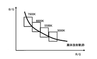
- light source color pixels are extracted from the normal image (S1104).
- a light source color pixel extraction method for example, color temperature (R / G, B / G) is calculated, and if it is included in the peripheral region of the black body radiation locus as shown in FIG. It is possible.
- data obtained by reducing the normal image to the size of 250 ⁇ 375 pixels calculated in step S1103 may be used.
- the light source spectrum data of the pixel estimated as the light source color is calculated (S1105). Since the pixel estimated as the light source color is assumed to have a constant spectral reflectance of the subject regardless of the wavelength (white subject), the spectrum of the light source can be estimated. That is, in the first embodiment, the processing for estimating the spectral reflectance t (x, y, ⁇ ) of the subject is performed in the equation (1), but in this embodiment, e ( ⁇ ) is estimated. It becomes.
- step S1104 is determined as the light source color in the color temperature evaluation, there is a possibility that the chromatic subject is misrecognized as the light source color.
- the light source spectrum data stored in advance in the correction information generation unit 120 is read (S106), compared with the estimated light source spectrum data, and it is determined again whether it is the light source color (S1107). Even if the color temperature is indistinguishable between the light source color and the subject color, it can be distinguished by comparing with the spectrum.
- the normal image is divided into regions (S1108), and based on the determination result in step S1107, a corrected image is generated based on the white balance correction coefficient for the normal image (S1109).
- the estimation of the light source and the generation of the correction coefficient may be performed for the entire image, or may be performed for each arbitrary pixel region. When one correction coefficient is used for the entire image, the area division processing in step S1108 is not necessary.
- the light source color pixel extraction process in step S1104 is performed using a normal image, but it may be determined using information on special wavelength pixels. That is, the color temperature may be calculated from the special wavelength pixel.
- the color temperature may be calculated from the special wavelength pixel.
- the RGB information is (R / G, B / G).
- the special wavelength pixels are arranged apart from the RGB pixels, there is a possibility that information on different subjects is handled as one information.
- step S1104 When importance is attached to light source estimation accuracy, normal image generation becomes difficult, but it is possible to use a CFA in which special wavelength pixels as shown in FIG. 18 are arranged together.
- the light source color pixel extraction process in step S1104 can be performed with high accuracy, and the light source spectrum estimated in step S1105 is directly used as the light source spectrum without comparison with the light source spectrum read in step S1106.
- the correction image generation processing in step S1109 may be used.
- processing in the digital process circuit 110 is different based on the configuration of the second embodiment. Specifically, the contents of the process performed by the spectrum estimation unit 119 are different.
- the light source spectrum is estimated after extracting the light source color pixels in the image, but in this modification, the spectrum is calculated for all the pixels of the special wavelength pixels (S1504).
- the spectrum estimation process cannot be performed as it is. Therefore, in this example, it is assumed that the light source is a constant light source (white light source) regardless of the wavelength, and spectrum estimation is performed.
- light source spectrum information is read (S1505).
- light source information having a spectrum with a bright line standing in a specific wavelength region such as a three-wavelength daylight fluorescent lamp shown in FIG. 20 is read.
- the spectral data estimated in step S1504 and the light source spectral data read in step S1504 are compared, and it is determined whether or not features such as bright lines in a specific wavelength region match to perform light source estimation (S1506).
- the light source that irradiates the subject has a spectrum having a characteristic such as a bright line, it is expected that the characteristic is also reflected in the estimated spectrum data.
- This modification is not suitable for detecting a light source having a broad spectrum over a wide wavelength region such as a sunlamp, but generally emits a bright line such as a fluorescent lamp that is considered difficult to correct white balance. It is effective for the light source.
- the normal image generating color filter 1071 having three or more bands and the correction information generating color filter 1072 having spectral sensitivity characteristics different from those of the normal image generating color filter 1071 are arranged in an array.
- the pixel value obtained using the image sensor 107 having the color filter array and the normal image generation color filter 1071 is interpolated to generate a normal image in which the pixel values of the missing pixels are interpolated.
- a spectrum estimation unit 119 that performs a spectrum estimation process based on a pixel value obtained by using the normal image generation unit 118 to perform, and at least the correction information generation color filter 1072, and a spectrum estimation value obtained by the spectrum estimation unit 119.
- a color filter corresponding to one band is assigned to each pixel.
- R, G, and B color filters are used as the normal image generation color filter 1071
- C1 and C2 color filters are used as the correction information generation color filter 1072.
- the normal image generation unit 118 performs interpolation processing of the pixel values obtained using the normal image generation color filter 1071, and generates a normal image in which the pixel values of the missing pixels are interpolated.
- the G pixel value is assigned to the pixel to which the G color filter is assigned. Only other pixel values of R, B, C1, and C2 cannot be obtained. Thus, since the pixel values for R, B, C1, and C2 are missing, this pixel is referred to as a missing pixel for R, B, C1, and C2.
- interpolation processing is performed using the R pixel values obtained in the pixels around the missing pixels, and the R pixel values in the pixels are estimated.
- interpolation processing is performed using pixel values obtained using the normal image generation color filter 1071, that is, pixel values obtained using the R, G, and B color filters. As a result, a normal image in which R, G, and B pixel values are obtained for all pixels is obtained.
- the spectrum estimation unit 119 performs spectrum estimation processing based on pixel values obtained using at least the correction information generation color filter 1072 out of the normal image generation color filter 1071 and the correction information generation color filter 1072. I do.
- a specific example of the spectrum estimation process is as described above.
- the correction information generation unit 120 generates correction information for correcting the pixel value of the normal image based on the spectrum estimation value.
- the corrected image generation unit 121 performs a normal image correction process based on the correction information to generate a corrected image.
- the use of the single-plate multiband image sensor 107 can suppress the cost and the enlargement of the apparatus.
- the correction information generating color filter without reducing the sample density of the normal image generating color filter as much as possible as compared with the Bayer array.
- the normal image generation color filter 1071 may include an R color filter, a G color filter, and a B color filter.
- the correction information generation color filter 1072 may be arranged in the color filter array at a lower sample density than any of the R color filter, the G color filter, and the B color filter.
- the G color filter of the normal image generation color filter 1071 is arranged in an odd-numbered odd-numbered column and an even-numbered even-numbered column, or an odd-numbered even-numbered column and an even-numbered odd-numbered column in the color filter array. May be.
- the color filter for G may be arranged on the checkered pattern as in the Bayer array.
- the correction information generation color filter 1072 is arranged at a lower density than the normal image generation color filter 1071. Therefore, as described with reference to FIG. 8, the number of pixel values obtained using the correction information generating color filter 1072 is smaller than the number of pixels of the entire normal image.
- the correction information generation unit 120 may generate correction information for a plurality of pixel values of the normal image based on data of one spectrum estimation value obtained from one pixel value in the spectrum estimation process.
- the imaging apparatus 101 uses a spectrum estimation value data as a region of interest that is a region of interest in a normal image including a subject image having information in a specific wavelength band.
- a display mode setting unit 150 that performs a display mode setting process on the detected region of interest.
- image processing is performed such that the attention area is displayed brightly while the outside of the attention area is displayed darkly, or the attention area is surrounded by a red line.
- the imaging apparatus 101 uses a special wavelength interpolation image used to generate correction information based on a pixel value obtained using the correction information generation color filter 1072.
- a special wavelength interpolation image generation unit 130 that performs generation processing may be included.
- the special wavelength interpolation image generation unit 130 performs interpolation processing of pixel values obtained using the correction information generation color filter as generation processing, and generates a special wavelength interpolation image in which pixel values of missing pixels are interpolated. May be.
- the spectrum estimation unit 119 may perform spectrum estimation processing based on the special wavelength interpolation image.
- the special wavelength interpolation image generation unit 130 may generate a special wavelength interpolation image having a resolution lower than that of the normal image generated by the normal image generation unit 118.
- the spectrum estimation part 119 may perform a spectrum estimation process with the resolution of a special wavelength interpolation image based on the pixel value of a special wavelength interpolation image at least.
- the correction information generation unit 120 may generate correction information for a plurality of pixel values of the normal image based on data of one spectrum estimation value obtained as a result of the spectrum estimation process. Then, the corrected image generation unit 121 may perform correction processing with the resolution of the normal image using the generated correction information.
- performing the correction process at the resolution of the normal image means that one correction information is used for the correction process for a plurality of pixel values of the normal image, as described above with reference to FIG.
- the spectrum estimation unit 119 may extract a light source color pixel representing a light source color from the normal image, estimate a light source spectrum of the extracted light source color pixel, and obtain a light source spectrum estimated value. Then, the correction information generation unit 120 may estimate the light source by comparing the light source spectrum estimated value data with the light source spectrum data stored in advance.
- the corrected image generation unit 121 may perform a correction process for correcting the white balance on the normal image based on the estimated light source.
- the correction information generation unit 120 may generate correction information for each of a plurality of areas set in the normal image. Then, the corrected image generation unit 121 may perform correction processing on the normal image using the correction information for each region in the normal image generated by the correction information generation unit 120.
- the correction information generation unit 120 performs a comparison process between the spectrum estimation value data estimated by the spectrum estimation unit 119 and the spectrum data to be detected stored in advance, and identifies based on the result of the comparison process
- the specific spectrum region having the spectrum may be detected, and the correction information may be generated based on the detection result of the detected specific spectrum region.
- the spectrum estimation unit 119 extracts a light source spectrum data measurement pixel representing the color of the light source from the special wavelength interpolation image, estimates a light source spectrum of the extracted light source spectrum data measurement pixel, and obtains a light source spectrum estimation value. Also good. Then, the corrected image generation unit 121 may perform a process of correcting the white balance on the normal image based on the estimated light source spectrum value.
- the spectrum estimation unit 119 may perform spectrum estimation on the special wavelength interpolation image based on the light source spectrum data of white light. Then, the correction information generation unit 120 may estimate the light source in the specific wavelength region by comparing the spectrum estimation value data with the light source spectrum data stored in advance.
- the spectrum estimation unit 119 does not read the pixel value obtained using the normal image generation color filter 1071, but the pixel obtained using the correction information generation color filter 1072 It is also possible to perform thinning readout for reading out values and perform spectrum estimation processing using the pixel values read out by thinning out.
- the normal image generation color filter 1071 and the correction information generation color filter 1072 of the image sensor 107 may be infrared filters having a peak wavelength in the wavelength range of infrared light.
- the wavelength band of infrared light may be a wavelength band of 790 nanometers to 820 nanometers, or 905 nanometers to 970 nanometers.
- the imaging apparatus 101 includes a normal image generation color filter 1071 having three or more bands and a correction information generation color filter 1072 having spectral sensitivity characteristics different from those of the normal image generation color filter 1071 in an array.
- the pixel value obtained using the image sensor 107 having the color filter array and the normal image generation color filter 1071 is interpolated to generate a normal image in which the pixel values of the missing pixels are interpolated.
- the display mode setting unit 150 to perform the display mode setting processing for the detected region of interest may include.
- the imaging apparatus or the like of the present embodiment may realize part or most of the processing by a program.
- a processor such as a CPU executes the program, thereby realizing the imaging apparatus of the present embodiment.
- a program stored in the information storage medium is read, and a processor such as a CPU executes the read program.
- the information storage medium (computer-readable medium) stores programs, data, and the like, and functions as an optical disk (DVD, CD, etc.), HDD (hard disk drive), or memory (card type). It can be realized by memory, ROM, etc.
- a processor such as a CPU performs various processes according to the present embodiment based on a program (data) stored in the information storage medium. That is, in the information storage medium, a program for causing a computer (an apparatus including an operation unit, a processing unit, a storage unit, and an output unit) to function as each unit of the present embodiment (a program for causing the computer to execute processing of each unit) Is memorized.
- 101 imaging device 102 imaging lens system, 103 lens driving mechanism, 104 lens driver, 105 exposure control mechanism, 106 exposure control driver, 107 image sensor (multiband image sensor, single plate multiband image sensor), 108 image sensor driver, 109 preprocess circuit, 110 digital process circuit, 111 card interface (card I / F), 112 image display system (LCD), 113 operation switch system (operation SW), 114 operation display system, 115 nonvolatile memory (EEPROM), 116 system controller (CPU), 117 memory card, 118 normal image generation unit, 119 spectrum estimation unit, 120 correction information generation unit, 123 signal processing unit, 124 light source detection sensor, 130 special wavelength interpolation image generation unit, 140 attention area detection unit, 150 display mode setting unit
Landscapes
- Engineering & Computer Science (AREA)
- Multimedia (AREA)
- Signal Processing (AREA)
- Computing Systems (AREA)
- Theoretical Computer Science (AREA)
- Physics & Mathematics (AREA)
- Spectroscopy & Molecular Physics (AREA)
- Color Television Image Signal Generators (AREA)
Priority Applications (1)
| Application Number | Priority Date | Filing Date | Title |
|---|---|---|---|
| US14/540,837 US9282305B2 (en) | 2012-10-23 | 2014-11-13 | Imaging device and image generation method |
Applications Claiming Priority (2)
| Application Number | Priority Date | Filing Date | Title |
|---|---|---|---|
| JP2012234002A JP5687676B2 (ja) | 2012-10-23 | 2012-10-23 | 撮像装置及び画像生成方法 |
| JP2012-234002 | 2012-10-23 |
Related Child Applications (1)
| Application Number | Title | Priority Date | Filing Date |
|---|---|---|---|
| US14/540,837 Continuation US9282305B2 (en) | 2012-10-23 | 2014-11-13 | Imaging device and image generation method |
Publications (1)
| Publication Number | Publication Date |
|---|---|
| WO2014065053A1 true WO2014065053A1 (ja) | 2014-05-01 |
Family
ID=50544433
Family Applications (1)
| Application Number | Title | Priority Date | Filing Date |
|---|---|---|---|
| PCT/JP2013/075622 Ceased WO2014065053A1 (ja) | 2012-10-23 | 2013-09-24 | 撮像装置及び画像生成方法 |
Country Status (3)
| Country | Link |
|---|---|
| US (1) | US9282305B2 (enExample) |
| JP (1) | JP5687676B2 (enExample) |
| WO (1) | WO2014065053A1 (enExample) |
Cited By (2)
| Publication number | Priority date | Publication date | Assignee | Title |
|---|---|---|---|---|
| WO2016140809A1 (en) * | 2015-03-04 | 2016-09-09 | Microsoft Technology Licensing, Llc | Sensing images and light sources |
| WO2019181125A1 (ja) * | 2018-03-22 | 2019-09-26 | ソニー株式会社 | 画像処理装置及び画像処理方法 |
Families Citing this family (31)
| Publication number | Priority date | Publication date | Assignee | Title |
|---|---|---|---|---|
| US8498695B2 (en) | 2006-12-22 | 2013-07-30 | Novadaq Technologies Inc. | Imaging system with a single color image sensor for simultaneous fluorescence and color video endoscopy |
| CN102036599B (zh) | 2008-03-18 | 2013-06-19 | 诺瓦达克技术公司 | 用于组合的全色反射和近红外成像的成像系统 |
| WO2014007279A1 (ja) * | 2012-07-06 | 2014-01-09 | 富士フイルム株式会社 | カラー撮像素子および撮像装置 |
| GB201221124D0 (en) * | 2012-11-23 | 2013-01-09 | Kromek Ltd | Method of spectral data detection and manipulation |
| US9372292B2 (en) * | 2013-12-13 | 2016-06-21 | Canon Kabushiki Kaisha | Imaging apparatus having light source identification and image quality correction functions and method for controlling imaging apparatus |
| JP5881916B1 (ja) * | 2014-05-09 | 2016-03-09 | オリンパス株式会社 | 固体撮像素子、内視鏡および内視鏡システム |
| CN107405093A (zh) * | 2015-04-08 | 2017-11-28 | 奥林巴斯株式会社 | 图像处理装置、摄像装置、图像处理方法和程序 |
| CA2998920A1 (en) | 2015-11-13 | 2017-05-18 | Novadaq Technologies ULC | Systems and methods for illumination and imaging of a target |
| US10980420B2 (en) | 2016-01-26 | 2021-04-20 | Stryker European Operations Limited | Configurable platform |
| USD916294S1 (en) | 2016-04-28 | 2021-04-13 | Stryker European Operations Limited | Illumination and imaging device |
| CN109311949B (zh) | 2016-05-11 | 2022-09-16 | 思拓凡生物工艺研发有限公司 | 储存分离基质的方法 |
| WO2017214730A1 (en) | 2016-06-14 | 2017-12-21 | Novadaq Technologies Inc. | Methods and systems for adaptive imaging for low light signal enhancement in medical visualization |
| EP4242743A3 (en) | 2017-02-10 | 2023-10-18 | Stryker European Operations Limited | Open-field handheld fluorescence imaging systems and methods |
| JP2019057797A (ja) * | 2017-09-20 | 2019-04-11 | パナソニックIpマネジメント株式会社 | 暗視撮像装置 |
| JPWO2019069414A1 (ja) * | 2017-10-04 | 2020-11-05 | オリンパス株式会社 | 内視鏡装置、画像処理方法およびプログラム |
| US11212500B2 (en) | 2017-12-05 | 2021-12-28 | Nikon Corporation | Image capture apparatus, electronic apparatus, and recording medium suppressing chroma in white balance correction performed based on color temperature |
| US10931902B2 (en) * | 2018-05-08 | 2021-02-23 | Semiconductor Components Industries, Llc | Image sensors with non-rectilinear image pixel arrays |
| US11417023B2 (en) * | 2018-10-04 | 2022-08-16 | Sony Corporation | Image processing device, image processing method, and program |
| CN113853631B (zh) * | 2019-07-25 | 2025-09-23 | 松下知识产权经营株式会社 | 图像数据处理方法、图像数据处理装置及图像数据处理系统 |
| US12372404B2 (en) * | 2020-07-01 | 2025-07-29 | Spectricity | Illuminant correction in an imaging system |
| US11696043B2 (en) * | 2020-07-01 | 2023-07-04 | Spectricity | White balance compensation using a spectral sensor system |
| CN112153356A (zh) * | 2020-09-16 | 2020-12-29 | Oppo广东移动通信有限公司 | 图像参数的确定方法、图像传感器、装置、电子设备及存储介质 |
| WO2022070227A1 (ja) * | 2020-09-29 | 2022-04-07 | 日本電気株式会社 | 設備診断システム、設備診断方法、及び、設備診断プログラムが格納された記録媒体 |
| TWI891951B (zh) * | 2021-01-06 | 2025-08-01 | 日商發那科股份有限公司 | 圖像處理裝置 |
| TW202303511A (zh) * | 2021-01-29 | 2023-01-16 | 日商索尼半導體解決方案公司 | 圖像處理裝置、圖像處理方法及圖像處理程式 |
| EP4300936A4 (en) * | 2021-03-23 | 2024-01-24 | Huawei Technologies Co., Ltd. | IMAGE SENSOR, IMAGE DATA ACQUISITION METHOD AND IMAGING DEVICE |
| KR102831119B1 (ko) * | 2021-05-26 | 2025-07-04 | 삼성전자주식회사 | 넓은 색역의 영상을 제공하는 영상 획득 장치 및 이를 포함하는 전자 장치 |
| KR102827126B1 (ko) * | 2021-08-27 | 2025-07-01 | 삼성전자주식회사 | 복수의 이미지 센서를 포함한 영상 획득 장치 및 이를 포함하는 전자 장치 |
| DE102022201523A1 (de) * | 2021-09-10 | 2023-03-16 | Fraunhofer-Gesellschaft zur Förderung der angewandten Forschung eingetragener Verein | Ein Bildsensor, ein Verfahren zum Betreiben eines Bildsensors, ein Verfahren zum Herstellen eines Bildsensors und ein stationäres Gerät oder ein Fahrzeug oder eine Drohne mit einem Bildsensor |
| CN116156139A (zh) * | 2021-11-18 | 2023-05-23 | 北京与光科技有限公司 | 图像的白平衡优化方法、装置和电子设备 |
| DE102023206089B4 (de) * | 2023-06-28 | 2025-01-23 | Volkswagen Aktiengesellschaft | Optischer Sensor, Umfelderkennungssystem und Fahrzeug |
Citations (6)
| Publication number | Priority date | Publication date | Assignee | Title |
|---|---|---|---|---|
| JP2005033609A (ja) * | 2003-07-08 | 2005-02-03 | Fuji Film Microdevices Co Ltd | 固体撮像装置及びデジタルカメラ |
| JP2006005500A (ja) * | 2004-06-16 | 2006-01-05 | Casio Comput Co Ltd | 撮像装置及び撮像方法、撮像素子 |
| JP2009181449A (ja) * | 2008-01-31 | 2009-08-13 | Sharp Corp | 画像処理装置および画像処理方法 |
| JP2009290694A (ja) * | 2008-05-30 | 2009-12-10 | Fujifilm Corp | 撮像装置 |
| JP2011109620A (ja) * | 2009-11-20 | 2011-06-02 | Canon Inc | 撮像装置および画像処理方法 |
| JP2012014668A (ja) * | 2010-06-04 | 2012-01-19 | Sony Corp | 画像処理装置、画像処理方法、プログラム、および電子装置 |
Family Cites Families (7)
| Publication number | Priority date | Publication date | Assignee | Title |
|---|---|---|---|---|
| US5629734A (en) | 1995-03-17 | 1997-05-13 | Eastman Kodak Company | Adaptive color plan interpolation in single sensor color electronic camera |
| JP2003087806A (ja) | 2001-09-12 | 2003-03-20 | Fuji Photo Film Co Ltd | マルチバンドカメラ用フィルターとその形成方法並びにこの方法のプログラム及びこれを記録した記録媒体 |
| JP4633129B2 (ja) | 2003-11-11 | 2011-02-16 | オリンパス株式会社 | マルチスペクトル画像撮影装置 |
| JP2006165975A (ja) * | 2004-12-07 | 2006-06-22 | Konica Minolta Photo Imaging Inc | 撮像素子、撮像装置、画像処理方法 |
| JP4981730B2 (ja) | 2008-03-26 | 2012-07-25 | 国立大学法人東京工業大学 | 分光画像生成装置及び分光画像生成方法 |
| US8546737B2 (en) * | 2009-10-30 | 2013-10-01 | Invisage Technologies, Inc. | Systems and methods for color binning |
| JP2011211317A (ja) | 2010-03-29 | 2011-10-20 | Olympus Corp | 光源検出装置 |
-
2012
- 2012-10-23 JP JP2012234002A patent/JP5687676B2/ja not_active Expired - Fee Related
-
2013
- 2013-09-24 WO PCT/JP2013/075622 patent/WO2014065053A1/ja not_active Ceased
-
2014
- 2014-11-13 US US14/540,837 patent/US9282305B2/en active Active
Patent Citations (6)
| Publication number | Priority date | Publication date | Assignee | Title |
|---|---|---|---|---|
| JP2005033609A (ja) * | 2003-07-08 | 2005-02-03 | Fuji Film Microdevices Co Ltd | 固体撮像装置及びデジタルカメラ |
| JP2006005500A (ja) * | 2004-06-16 | 2006-01-05 | Casio Comput Co Ltd | 撮像装置及び撮像方法、撮像素子 |
| JP2009181449A (ja) * | 2008-01-31 | 2009-08-13 | Sharp Corp | 画像処理装置および画像処理方法 |
| JP2009290694A (ja) * | 2008-05-30 | 2009-12-10 | Fujifilm Corp | 撮像装置 |
| JP2011109620A (ja) * | 2009-11-20 | 2011-06-02 | Canon Inc | 撮像装置および画像処理方法 |
| JP2012014668A (ja) * | 2010-06-04 | 2012-01-19 | Sony Corp | 画像処理装置、画像処理方法、プログラム、および電子装置 |
Cited By (5)
| Publication number | Priority date | Publication date | Assignee | Title |
|---|---|---|---|---|
| WO2016140809A1 (en) * | 2015-03-04 | 2016-09-09 | Microsoft Technology Licensing, Llc | Sensing images and light sources |
| US9696470B2 (en) | 2015-03-04 | 2017-07-04 | Microsoft Technology Licensing, Llc | Sensing images and light sources via visible light filters |
| CN107407600A (zh) * | 2015-03-04 | 2017-11-28 | 微软技术许可有限责任公司 | 感测图像和光源 |
| CN107407600B (zh) * | 2015-03-04 | 2019-08-23 | 微软技术许可有限责任公司 | 感测图像和光源 |
| WO2019181125A1 (ja) * | 2018-03-22 | 2019-09-26 | ソニー株式会社 | 画像処理装置及び画像処理方法 |
Also Published As
| Publication number | Publication date |
|---|---|
| US20150070528A1 (en) | 2015-03-12 |
| JP5687676B2 (ja) | 2015-03-18 |
| US9282305B2 (en) | 2016-03-08 |
| JP2014086862A (ja) | 2014-05-12 |
Similar Documents
| Publication | Publication Date | Title |
|---|---|---|
| JP5687676B2 (ja) | 撮像装置及び画像生成方法 | |
| US9179113B2 (en) | Image processing device, and image processing method, and program | |
| JP5904213B2 (ja) | 画像処理装置、および画像処理方法、並びにプログラム | |
| US8754957B2 (en) | Image processing apparatus and method | |
| JP4501855B2 (ja) | 画像信号処理装置、撮像装置、および画像信号処理方法、並びにコンピュータ・プログラム | |
| CN104247409B (zh) | 图像处理装置、图像处理方法以及程序 | |
| JP2013219705A (ja) | 画像処理装置、および画像処理方法、並びにプログラム | |
| US8525920B2 (en) | Imaging apparatus and signal processing method for checking a photographed image in a multi-band camera immediately | |
| WO2016047240A1 (ja) | 画像処理装置、撮像素子、撮像装置および画像処理方法 | |
| JP5943393B2 (ja) | 撮像装置 | |
| US9843782B2 (en) | Interpolation device, storage medium, and method with multi-band color filter and noise reduced reference image | |
| JP5464982B2 (ja) | 撮像装置および画像処理方法 | |
| JP5718138B2 (ja) | 画像信号処理装置及びプログラム | |
| US8237829B2 (en) | Image processing device, image processing method, and imaging apparatus | |
| US20110149126A1 (en) | Multiband image pickup method and device | |
| JP5738904B2 (ja) | 画像処理装置、撮像装置、画像処理方法及びプログラム | |
| CN107736020A (zh) | 摄像装置、图像处理装置、图像处理方法和图像处理程序 | |
| KR20150123738A (ko) | 화상처리장치 및 화상처리방법 | |
| JP6086829B2 (ja) | 画像処理装置及び画像処理方法 | |
| JP2011041094A5 (enExample) | ||
| WO2013111824A1 (ja) | 画像処理装置、撮像装置及び画像処理方法 | |
| JP2016184776A (ja) | 画像処理装置と画像処理方法とプログラムおよび撮像装置 | |
| KR20110035632A (ko) | 디지털 카메라에서 결여된 색상 성분을 복원하는 방법 및 그 장치 | |
| JP2020150411A (ja) | 撮像装置及び画像処理方法 |
Legal Events
| Date | Code | Title | Description |
|---|---|---|---|
| 121 | Ep: the epo has been informed by wipo that ep was designated in this application |
Ref document number: 13849952 Country of ref document: EP Kind code of ref document: A1 |
|
| NENP | Non-entry into the national phase |
Ref country code: DE |
|
| 122 | Ep: pct application non-entry in european phase |
Ref document number: 13849952 Country of ref document: EP Kind code of ref document: A1 |