WO2014064894A1 - 圧縮機不純物除去システム - Google Patents
圧縮機不純物除去システム Download PDFInfo
- Publication number
- WO2014064894A1 WO2014064894A1 PCT/JP2013/005973 JP2013005973W WO2014064894A1 WO 2014064894 A1 WO2014064894 A1 WO 2014064894A1 JP 2013005973 W JP2013005973 W JP 2013005973W WO 2014064894 A1 WO2014064894 A1 WO 2014064894A1
- Authority
- WO
- WIPO (PCT)
- Prior art keywords
- impurity
- drain
- stage
- exhaust gas
- compressor
- Prior art date
- Legal status (The legal status is an assumption and is not a legal conclusion. Google has not performed a legal analysis and makes no representation as to the accuracy of the status listed.)
- Ceased
Links
Images

Classifications
-
- B—PERFORMING OPERATIONS; TRANSPORTING
- B01—PHYSICAL OR CHEMICAL PROCESSES OR APPARATUS IN GENERAL
- B01D—SEPARATION
- B01D53/00—Separation of gases or vapours; Recovering vapours of volatile solvents from gases; Chemical or biological purification of waste gases, e.g. engine exhaust gases, smoke, fumes, flue gases, aerosols
- B01D53/34—Chemical or biological purification of waste gases
- B01D53/74—General processes for purification of waste gases; Apparatus or devices specially adapted therefor
- B01D53/75—Multi-step processes
-
- B—PERFORMING OPERATIONS; TRANSPORTING
- B01—PHYSICAL OR CHEMICAL PROCESSES OR APPARATUS IN GENERAL
- B01D—SEPARATION
- B01D53/00—Separation of gases or vapours; Recovering vapours of volatile solvents from gases; Chemical or biological purification of waste gases, e.g. engine exhaust gases, smoke, fumes, flue gases, aerosols
- B01D53/002—Separation of gases or vapours; Recovering vapours of volatile solvents from gases; Chemical or biological purification of waste gases, e.g. engine exhaust gases, smoke, fumes, flue gases, aerosols by condensation
-
- B—PERFORMING OPERATIONS; TRANSPORTING
- B01—PHYSICAL OR CHEMICAL PROCESSES OR APPARATUS IN GENERAL
- B01D—SEPARATION
- B01D53/00—Separation of gases or vapours; Recovering vapours of volatile solvents from gases; Chemical or biological purification of waste gases, e.g. engine exhaust gases, smoke, fumes, flue gases, aerosols
- B01D53/34—Chemical or biological purification of waste gases
- B01D53/346—Controlling the process
-
- B—PERFORMING OPERATIONS; TRANSPORTING
- B01—PHYSICAL OR CHEMICAL PROCESSES OR APPARATUS IN GENERAL
- B01D—SEPARATION
- B01D53/00—Separation of gases or vapours; Recovering vapours of volatile solvents from gases; Chemical or biological purification of waste gases, e.g. engine exhaust gases, smoke, fumes, flue gases, aerosols
- B01D53/34—Chemical or biological purification of waste gases
- B01D53/46—Removing components of defined structure
- B01D53/60—Simultaneously removing sulfur oxides and nitrogen oxides
-
- B—PERFORMING OPERATIONS; TRANSPORTING
- B01—PHYSICAL OR CHEMICAL PROCESSES OR APPARATUS IN GENERAL
- B01D—SEPARATION
- B01D53/00—Separation of gases or vapours; Recovering vapours of volatile solvents from gases; Chemical or biological purification of waste gases, e.g. engine exhaust gases, smoke, fumes, flue gases, aerosols
- B01D53/34—Chemical or biological purification of waste gases
- B01D53/74—General processes for purification of waste gases; Apparatus or devices specially adapted therefor
- B01D53/77—Liquid phase processes
- B01D53/78—Liquid phase processes with gas-liquid contact
-
- B—PERFORMING OPERATIONS; TRANSPORTING
- B01—PHYSICAL OR CHEMICAL PROCESSES OR APPARATUS IN GENERAL
- B01D—SEPARATION
- B01D53/00—Separation of gases or vapours; Recovering vapours of volatile solvents from gases; Chemical or biological purification of waste gases, e.g. engine exhaust gases, smoke, fumes, flue gases, aerosols
- B01D53/34—Chemical or biological purification of waste gases
- B01D53/74—General processes for purification of waste gases; Apparatus or devices specially adapted therefor
- B01D53/77—Liquid phase processes
- B01D53/79—Injecting reactants
-
- C—CHEMISTRY; METALLURGY
- C01—INORGANIC CHEMISTRY
- C01B—NON-METALLIC ELEMENTS; COMPOUNDS THEREOF; METALLOIDS OR COMPOUNDS THEREOF NOT COVERED BY SUBCLASS C01C
- C01B32/00—Carbon; Compounds thereof
- C01B32/50—Carbon dioxide
-
- F—MECHANICAL ENGINEERING; LIGHTING; HEATING; WEAPONS; BLASTING
- F23—COMBUSTION APPARATUS; COMBUSTION PROCESSES
- F23J—REMOVAL OR TREATMENT OF COMBUSTION PRODUCTS OR COMBUSTION RESIDUES; FLUES
- F23J15/00—Arrangements of devices for treating smoke or fumes
- F23J15/06—Arrangements of devices for treating smoke or fumes of coolers
-
- B—PERFORMING OPERATIONS; TRANSPORTING
- B01—PHYSICAL OR CHEMICAL PROCESSES OR APPARATUS IN GENERAL
- B01D—SEPARATION
- B01D2251/00—Reactants
- B01D2251/40—Alkaline earth metal or magnesium compounds
- B01D2251/404—Alkaline earth metal or magnesium compounds of calcium
-
- B—PERFORMING OPERATIONS; TRANSPORTING
- B01—PHYSICAL OR CHEMICAL PROCESSES OR APPARATUS IN GENERAL
- B01D—SEPARATION
- B01D2251/00—Reactants
- B01D2251/60—Inorganic bases or salts
- B01D2251/602—Oxides
-
- B—PERFORMING OPERATIONS; TRANSPORTING
- B01—PHYSICAL OR CHEMICAL PROCESSES OR APPARATUS IN GENERAL
- B01D—SEPARATION
- B01D2251/00—Reactants
- B01D2251/60—Inorganic bases or salts
- B01D2251/604—Hydroxides
-
- B—PERFORMING OPERATIONS; TRANSPORTING
- B01—PHYSICAL OR CHEMICAL PROCESSES OR APPARATUS IN GENERAL
- B01D—SEPARATION
- B01D2251/00—Reactants
- B01D2251/60—Inorganic bases or salts
- B01D2251/606—Carbonates
-
- B—PERFORMING OPERATIONS; TRANSPORTING
- B01—PHYSICAL OR CHEMICAL PROCESSES OR APPARATUS IN GENERAL
- B01D—SEPARATION
- B01D2257/00—Components to be removed
- B01D2257/20—Halogens or halogen compounds
- B01D2257/204—Inorganic halogen compounds
- B01D2257/2045—Hydrochloric acid
-
- B—PERFORMING OPERATIONS; TRANSPORTING
- B01—PHYSICAL OR CHEMICAL PROCESSES OR APPARATUS IN GENERAL
- B01D—SEPARATION
- B01D2257/00—Components to be removed
- B01D2257/30—Sulfur compounds
- B01D2257/302—Sulfur oxides
-
- B—PERFORMING OPERATIONS; TRANSPORTING
- B01—PHYSICAL OR CHEMICAL PROCESSES OR APPARATUS IN GENERAL
- B01D—SEPARATION
- B01D2257/00—Components to be removed
- B01D2257/40—Nitrogen compounds
- B01D2257/404—Nitrogen oxides other than dinitrogen oxide
-
- B—PERFORMING OPERATIONS; TRANSPORTING
- B01—PHYSICAL OR CHEMICAL PROCESSES OR APPARATUS IN GENERAL
- B01D—SEPARATION
- B01D2257/00—Components to be removed
- B01D2257/50—Carbon oxides
- B01D2257/504—Carbon dioxide
-
- B—PERFORMING OPERATIONS; TRANSPORTING
- B01—PHYSICAL OR CHEMICAL PROCESSES OR APPARATUS IN GENERAL
- B01D—SEPARATION
- B01D2257/00—Components to be removed
- B01D2257/60—Heavy metals or heavy metal compounds
- B01D2257/602—Mercury or mercury compounds
-
- B—PERFORMING OPERATIONS; TRANSPORTING
- B01—PHYSICAL OR CHEMICAL PROCESSES OR APPARATUS IN GENERAL
- B01D—SEPARATION
- B01D2257/00—Components to be removed
- B01D2257/80—Water
-
- B—PERFORMING OPERATIONS; TRANSPORTING
- B01—PHYSICAL OR CHEMICAL PROCESSES OR APPARATUS IN GENERAL
- B01D—SEPARATION
- B01D2258/00—Sources of waste gases
- B01D2258/02—Other waste gases
- B01D2258/0283—Flue gases
-
- F—MECHANICAL ENGINEERING; LIGHTING; HEATING; WEAPONS; BLASTING
- F23—COMBUSTION APPARATUS; COMBUSTION PROCESSES
- F23J—REMOVAL OR TREATMENT OF COMBUSTION PRODUCTS OR COMBUSTION RESIDUES; FLUES
- F23J2215/00—Preventing emissions
- F23J2215/50—Carbon dioxide
-
- F—MECHANICAL ENGINEERING; LIGHTING; HEATING; WEAPONS; BLASTING
- F23—COMBUSTION APPARATUS; COMBUSTION PROCESSES
- F23J—REMOVAL OR TREATMENT OF COMBUSTION PRODUCTS OR COMBUSTION RESIDUES; FLUES
- F23J2900/00—Special arrangements for conducting or purifying combustion fumes; Treatment of fumes or ashes
- F23J2900/15061—Deep cooling or freezing of flue gas rich of CO2 to deliver CO2-free emissions, or to deliver liquid CO2
-
- Y—GENERAL TAGGING OF NEW TECHNOLOGICAL DEVELOPMENTS; GENERAL TAGGING OF CROSS-SECTIONAL TECHNOLOGIES SPANNING OVER SEVERAL SECTIONS OF THE IPC; TECHNICAL SUBJECTS COVERED BY FORMER USPC CROSS-REFERENCE ART COLLECTIONS [XRACs] AND DIGESTS
- Y02—TECHNOLOGIES OR APPLICATIONS FOR MITIGATION OR ADAPTATION AGAINST CLIMATE CHANGE
- Y02E—REDUCTION OF GREENHOUSE GAS [GHG] EMISSIONS, RELATED TO ENERGY GENERATION, TRANSMISSION OR DISTRIBUTION
- Y02E20/00—Combustion technologies with mitigation potential
- Y02E20/32—Direct CO2 mitigation
-
- Y—GENERAL TAGGING OF NEW TECHNOLOGICAL DEVELOPMENTS; GENERAL TAGGING OF CROSS-SECTIONAL TECHNOLOGIES SPANNING OVER SEVERAL SECTIONS OF THE IPC; TECHNICAL SUBJECTS COVERED BY FORMER USPC CROSS-REFERENCE ART COLLECTIONS [XRACs] AND DIGESTS
- Y02—TECHNOLOGIES OR APPLICATIONS FOR MITIGATION OR ADAPTATION AGAINST CLIMATE CHANGE
- Y02E—REDUCTION OF GREENHOUSE GAS [GHG] EMISSIONS, RELATED TO ENERGY GENERATION, TRANSMISSION OR DISTRIBUTION
- Y02E20/00—Combustion technologies with mitigation potential
- Y02E20/34—Indirect CO2mitigation, i.e. by acting on non CO2directly related matters of the process, e.g. pre-heating or heat recovery
-
- Y—GENERAL TAGGING OF NEW TECHNOLOGICAL DEVELOPMENTS; GENERAL TAGGING OF CROSS-SECTIONAL TECHNOLOGIES SPANNING OVER SEVERAL SECTIONS OF THE IPC; TECHNICAL SUBJECTS COVERED BY FORMER USPC CROSS-REFERENCE ART COLLECTIONS [XRACs] AND DIGESTS
- Y02—TECHNOLOGIES OR APPLICATIONS FOR MITIGATION OR ADAPTATION AGAINST CLIMATE CHANGE
- Y02P—CLIMATE CHANGE MITIGATION TECHNOLOGIES IN THE PRODUCTION OR PROCESSING OF GOODS
- Y02P20/00—Technologies relating to chemical industry
- Y02P20/151—Reduction of greenhouse gas [GHG] emissions, e.g. CO2
Definitions
- the present invention relates to a compressor impurity removal system, and more particularly to a compressor impurity removal system in which impurities contained in exhaust gas from an oxygen combustion apparatus can be removed by a simple device.
- Patent Document 1 As an exhaust gas treatment apparatus for a coal fired boiler for oxygen combustion as described above, there is one disclosed in Patent Document 1.
- Patent Document 1 in addition to carbon dioxide (CO 2 ), in addition to carbon dioxide (CO 2 ), nitrogen oxides (NO x ) and sulfur oxides (SO x X ), mercury (Hg), hydrogen chloride (HCl), and impurities such as dust are known to be contained, and these impurities need to be removed.
- sulfur oxide (SO X ) dissolves in water by contact with water to become sulfuric acid (H 2 SO 4 ), and hydrogen chloride (HCl) becomes hydrochloric acid by dissolving with water.
- sulfur oxide (SO X ) dissolves in water by contact with water to become sulfuric acid (H 2 SO 4 ), and hydrogen chloride (HCl) becomes hydrochloric acid by dissolving with water.
- HCl hydrogen chloride
- Such water-soluble sulfur oxides and hydrogen chloride can be separated by contacting with water.
- nitrogen oxides (NO X ) that are the impurities
- nitrogen dioxide (NO 2 ) is separated by contacting with water and dissolving in water to form nitric acid (HNO 3 ).
- O 2 oxygen
- this nitric oxide (NO) is insoluble in water. For this reason, it cannot be removed by water spray or the like.
- Patent Document 1 a desulfurization apparatus that is called wet by a spray tower system or a packed tower system that is used in a conventional air fired boiler is provided. Removal of sulfur oxides is performed. Also, since nitrogen and nitrogen oxides derived from coal raw materials are generated in the exhaust gas from coal fired boilers that perform oxyfuel combustion, a denitration device such as a catalyst system is provided upstream of the desulfurization device to oxidize nitrogen and nitrogen. Things are being removed.
- Patent Document 1 both a wet desulfurization apparatus such as a spray tower system or a packed tower system and a denitration apparatus using a catalyst system are provided to remove impurities in the exhaust gas.
- a wet desulfurization apparatus such as a spray tower system or a packed tower system
- a denitration apparatus using a catalyst system are provided to remove impurities in the exhaust gas.
- the apparatus for removing impurities becomes very large and complicated, increasing the equipment cost.
- the present invention provides a compressor impurity removal system capable of removing nitrogen oxide, which is an impurity contained in exhaust gas from an oxyfuel combustion device, at a low cost with a simple device. With the goal.
- the present invention is a compressor impurity removal system for removing impurities in the exhaust gas before supplying the carbon dioxide-based exhaust gas from the oxyfuel combustion device to the carbon dioxide liquefaction device,
- the exhaust gas from the oxycombustor is supplied to the carbon dioxide liquefier and compressed in stages to the target pressure to be liquefied, and the exhaust gas compressed by each compressor is cooled, and the moisture condensed by cooling is drained.
- a multi-stage impurity separation device having an aftercooler adapted to be taken out as An alkaline agent supply device that supplies an alkaline agent upstream of an aftercooler in the latter-stage impurity separation device and takes out drain containing the alkaline agent from which impurities in the exhaust gas are removed from the aftercooler in the latter-stage impurity separation device;
- the present invention relates to a compressor impurity removal system including a circulation line for supplying drain taken out from an aftercooler in a rear-stage impurity separation device to an upstream side of the after-cooler in the front-stage impurity separation device.
- a drain tank that stores a certain amount of drain taken out from an aftercooler in an impurity separation device at a subsequent stage
- a pH detector that measures the pH of the drain stored in the drain tank
- the pH detection It is preferable to have a controller that outputs a supply amount signal to the alkaline agent supply device and adjusts the supply amount of the alkaline agent so that the detected pH value detected by the vessel is maintained at a preset value.
- another drain tank that stores a certain amount of drain from the aftercooler in the impurity separation device in the previous stage, and another pH that measures the pH of the drain stored in the other drain tank
- a supply signal for the controller by outputting a command signal to the controller so that the pH detection value detected by the other pH detector is held at a preset correction value. It is preferable to provide another controller for correcting the above.
- the compressor impurity removal system may further include an impurity detector provided downstream of the aftercooler in the subsequent impurity separation apparatus, and the controller to which the impurity detection value of the impurity detector is input.
- the vessel is preferably configured to issue a command to increase the supply of the alkaline agent by the alkaline agent supply device when the impurity detection value of the impurity detector exceeds a predetermined value.
- the alkaline agent is supplied to the upstream side of the aftercooler in the rear-stage impurity separation device including the compressor and the aftercooler. Then, it is taken out together with the drain that flows out from the after cooler in the impurity separation apparatus in the latter stage, containing the alkaline agent. Since the drain taken out from the aftercooler in the rear-stage impurity separator is supplied to at least the upstream side of the aftercooler in the front-stage impurity separator, the impurities composed of sulfur oxides in the exhaust gas from the after-cooler in the front-stage impurity separator It is taken out with the drain.
- the desulfurization apparatus and the denitration apparatus can be reduced in size or omitted, and an excellent effect can be achieved in that the equipment cost can be greatly reduced.
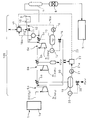
- FIG. 1 is a system diagram showing an embodiment of a compressor impurity removal system 100 of the present invention provided in an oxyfuel combustion apparatus.
- reference numeral 1 denotes an oxyfuel combustion apparatus including a coal fired boiler 1 a that oxidizes pulverized coal, and exhaust gas 2 mainly composed of carbon dioxide (CO 2 ) is discharged from the oxyfuel combustion apparatus 1.
- the exhaust gas 2 is compressed to a predetermined target pressure before the carbon dioxide liquefaction apparatus 3.
- a compressor impurity removal system 100 that removes impurities in the exhaust gas 2 is provided.
- a compressor impurity removal system 100 shown in FIG. 1 includes a plurality of compressors 4a, 4b, and 4c that compress the exhaust gas 2 from the oxyfuel combustion apparatus 1 stepwise to a target pressure, and the compressors 4a, 4b, and 4c.
- the exhaust gas 2 compressed in step 1 is cooled at each subsequent stage, and aftercoolers 5a, 5b, and 5c (coolers) that take out the moisture condensed by cooling as drains are provided in a plurality of stages (three stages in the illustrated example).
- Separators 6a, 6b and 6c are provided.
- a cooler provided between multistage compressors is called an intercooler. In the present invention, all the coolers are described as aftercoolers 5a, 5b, and 5c in order to simplify the description.
- the cooling temperature by the aftercooler 5 is preferably -30 ° C.
- the single compressor 4 cannot boost the exhaust gas 2 to the target pressure of 2.5 MPa at a stretch
- three compressors 4 a, 4 b, 4 c are installed and 0.75 MPa, 1 Impurity separation devices 6a, 6b and 6c are configured to be compressed in three stages such as .5 MPa and 2.5 MPa.
- the number of compressors 4a, 4b, 4c installed may be four or more, and any number can be installed.
- the first-stage impurity separation device 6a set to the above pressure, most of the water in the exhaust gas 2 is taken out as drain, and in the middle-stage impurity separation device 6b, a small amount of drain is taken out, and the last-stage impurity is removed. A smaller amount of drain is taken out by the separation device 6c.
- the compressor impurity removal system 100 impurities in the exhaust gas 2 are removed together with the drain, but the concentration of mercury (Hg) in carbon dioxide that has passed through the compressor impurity removal system 100 is higher than the set target value.
- a mercury removal tower 7 is installed downstream of the compressor impurity removal system 100 to remove mercury with an adsorbent or the like (the mercury removal tower 7 is indicated by a broken line in the drawing).
- a dryer 8 for removing moisture contained in the carbon dioxide supplied to the carbon dioxide liquefying device 3 is provided in the preceding stage of the carbon dioxide liquefying device 3.
- an alkaline agent in which the alkaline agent 10 in the alkaline agent tank 9 is supplied by a pump 11 to the inlet (upstream side) of the aftercooler 5c in the impurity separation device 6c at the last stage.
- a supply device 12 is provided.
- the position where the alkali agent 10 is supplied by the alkali agent supply device 12 is most preferably the inlet of the last-stage after cooler 5c because the pressure of the last-stage impurity separation device 6c is the highest.
- the position at which the alkaline agent 10 is supplied by the alkaline agent supply device 12 can be the inlet of the upstream aftercooler 5b close to the final impurity separation device 6c.
- caustic soda NaOH
- magnesium hydroxide magnesium hydroxide or the like which has good dispersibility and does not cause sticking or the like
- limestone CaCO 3
- quicklime CaO
- slaked lime Ca (OH) 2
- a drain tank 13 is provided in which a certain amount of drain taken out from the aftercooler 5c in the impurity separation device 6c at the last stage is stored.
- the drain tank 13 is provided with a level controller 14, and the level controller 14 has an opening of a take-off valve 15 provided at the drain outlet (downstream side) of the drain tank 13 so that the detected value always maintains a constant value. To adjust.
- the drain taken out from the take-off valve 15 of the drain tank 13 is supplied to the inlet (upstream side) of the after cooler 5a in the front-stage impurity separation device 6a via the circulation line 30.
- the inlet of the aftercooler 5a means between the aftercooler 5a and the compressor 4a located on the upstream side of the aftercooler 5a.
- the position where the drain of the drain tank 13 is supplied by the circulation line 30 may be the inlet (upstream side) of the rear-stage after cooler 5b close to the front-stage impurity separation device 6a.
- the drain tank 13 is provided with a pH detector 16 for measuring the pH of the stored drain, and the pH detection value 16 a detected by the pH detector 16 is input to the controller 17. Then, the controller 17 outputs a supply amount signal 17a to the alkaline agent supply device 12 so that the pH detection value 16a detected by the pH detector 16 is held at a preset set value I. The supply amount of the alkaline agent 10 is adjusted.
- an impurity detector 18 for detecting impurities (for example, nitrogen oxides) in the exhaust gas 2 is installed at the outlet (downstream side) from which the exhaust gas 2 is led out from the aftercooler 5c in the impurity separation device 6c at the last stage.
- the impurity detection value 18 a of the impurity detector 18 is input to the controller 17. Then, the controller 17 increases the supply of the alkaline agent 10 by the alkaline agent supply device 12 as an emergency when, for example, the nitrogen oxide impurity detection value 18a by the impurity detector 18 exceeds a predetermined value. Control is performed to output a supply amount signal 17a (increase command).
- the location of the impurity detector 18 is preferably the outlet of the aftercooler 5c so that the impurities in the drain can be detected quickly, but the dryer 8 (or mercury removal) from the aftercooler 5c downstream of the aftercooler 5c. It can also be installed at a position up to the tower 7).
- the compressor 4a of 6a is preferably composed of a corrosion prevention material made of Hastelloy (registered trademark), which is a heat-resistant nickel alloy.
- the corrosion preventing material is not limited to the heat-resistant nickel alloy, and may be composed of other metals, alloys, inorganic substances, etc. as long as they have corrosion resistance and heat resistance.
- the compressor 4a may be a gear turbocharger type compressor having no blades in addition to the compressor having blades (blades).
- the compressor 4a is pressurized to 0.7 MPa.
- the exhaust gas 2 pressurized to 0.7 MPa by the compressor 4a is cooled by being supplied to the adjacent after-cooler 5a together with the drain from the drain tank 13 supplied by the circulation line 30, and a large amount from the after-cooler 5a. Drain is taken out.
- the exhaust gas 2 cooled by the aftercooler 5a is guided to the compressor 4b in the latter (next stage) impurity separation device 6b and pressurized to 1.5 MPa, and the exhaust gas 2 pressurized to 1.5 MPa is adjacent to the exhaust gas 2
- the cooler is cooled by the aftercooler 5b, and a small amount of drain is taken out from the aftercooler 5b as compared with the aftercooler 5a.
- the exhaust gas 2 cooled by the after-cooler 5b is guided to the compressor 4c in the final impurity separation device 6c and pressurized to 2.5 MPa.
- the exhaust gas 2 pressurized to 2.5 MPa by the compressor 4 c is supplied to the adjacent after cooler 5 c together with the alkaline agent 10 supplied from the alkaline agent supply device 12 and cooled.
- the drain containing the alkaline agent 10 is taken out from the aftercooler 5 c and supplied to the drain tank 13.
- the exhaust gas 2 introduced into the aftercooler 5c in the impurity separation device 6c at the last stage is sequentially pressurized by the compressors 4a, 4b, and 4c and is pressurized to 2.5 MPa.
- Nitrogen oxide (NO) is converted into water-soluble nitrogen oxide (NO 2 ) by oxidization being promoted by pressurization.
- the alkaline agent 10 is supplied to the upstream side of the aftercooler 5c in the impurity separation device 6c at the last stage, and the pH is kept high, so that the nitrogen oxide is more soluble in the drain, and thereby the nitrogen oxide is oxidized. Objects are removed with a high removal rate.
- the drain in the drain tank 13 is passed through the circulation line 30 to the after cooler 5a in the foremost impurity separation device 6a.
- sulfur oxides and hydrogen chloride which are water-soluble impurities in the exhaust gas 2 introduced into the aftercooler 5a
- the unreacted alkaline agent 10 supplied to the upstream side of the aftercooler 5a by the circulation line 30. It will be effectively removed. That is, sulfur oxides and hydrogen chloride, which are water-soluble impurities, are removed at a relatively high removal rate by the drain taken out in large quantities from the front-stage impurity separation device 6a.
- the drain containing the unreacted alkaline agent 10 is supplied to the upstream side of the aftercooler 5a in the impurity separation device 6a of the previous stage by the circulation line 30, the sulfur oxide and the hydrogen chloride The removal rate is further increased.
- the drain containing impurities is supplied to a wastewater treatment apparatus (not shown) and processed.
- the carbon dioxide from which impurities in the exhaust gas 2 have been removed by the compressor impurity removal system 100 is removed from the mercury by the mercury removal tower 7 as necessary, and sent to the dryer 8 to remove moisture. Then, it is supplied to the carbon dioxide liquefier 3 and liquefied by cooling.
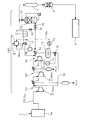
- FIG. 2 is a system diagram showing another embodiment of the compressor impurity removal system according to the present invention.
- the drain from the after cooler 5a is fixed to the after cooler 5a of the impurity separation device 6a in the foremost stage.
- Another drain tank 19 for storing the amount is provided.
- Another drain tank 19 is provided with a level controller 20, and the level controller 20 has an extraction valve 20 provided at the outlet (downstream side) of the other drain tank 19 so that the detected value always maintains a constant value. The opening of 'is adjusted.
- another drain tank 19 is provided with another pH detector 21 for measuring the pH of the stored drain, and the pH detection value 21a detected by the other pH detector 21 is a different controller. 22 is input. Then, another controller 22 outputs a command signal 23 to the controller 17 so that the pH detection value 21a detected by the other pH detector 21 is held at the preset correction value II. Thus, the supply amount signal 17a of the controller 17 is corrected.
- the pH of the drain in the drain tank 13 can be set in the range of about 4-6.
- the command signal 23 is sent from another controller 22 to the controller 17 so that the drain pH detection value 21 a of the other drain tank 19 is held at the correction setting value II.
- the supply amount signal 17a of the controller 17 is corrected, and as a result, the concentration of the alkaline agent 10 in the drain taken out to another drain tank 19 is suitably maintained.
- the removal rate of impurities, particularly sulfur oxides and hydrogen chloride, by the impurity separation device 6a in the foremost stage is greatly increased.
- FIG. 3 is a system diagram showing a modification of the compressor impurity removal system according to the present invention.
- a bypass duct 25 is provided downstream of the last impurity separation device 6 c downstream of the compressor impurity removal system 100, and a wet desulfurization / denitration device 26 is provided in the bypass duct 25.
- switching valves 27, 28, and 29 are provided so that the desulfurization / denitration device 26 can be switched between a flow through which the exhaust gas 2 is passed and a flow through which the exhaust gas 2 is not passed.
- the desulfurization / denitration device 26 In the configuration in which the desulfurization / denitration device 26 is provided in the bypass duct 25, impurities in the exhaust gas can be further reduced when necessary by supplying the exhaust gas 2 to the desulfurization / denitration device 26 as necessary. At this time, since the amount (volume) of the exhaust gas 2 guided to the desulfurization / denitration apparatus 26 by the compression by the compressor impurity removal system 100 is remarkably small, the desulfurization / denitration apparatus 26 is remarkably small (conventional number). Sufficient 1) can be used.
- the alkaline agent is supplied to the upstream side of the aftercooler 5c in the rear-stage impurity separation device 6c, and the exhaust gas is discharged from the aftercooler 5c in the rear-stage impurity separation device 6c.
- the alkaline agent supply device 12 is adapted to take out the drain containing the alkaline agent from which the impurities are removed, and the drain taken out from the after cooler 5c in the subsequent impurity separation device 6c is further removed from the after cooler 5a in the previous impurity separation device 6a. Therefore, the impurities in the exhaust gas 2 can be effectively removed at a low cost with a simple device.
- nitrogen monoxide (NO) in the exhaust gas 2 is changed to water-soluble nitrogen oxide (NO 2 ).
- the alkaline agent 10 is supplied to the upstream side of the aftercooler 5c that cools the exhaust gas 2, the pH of the drain is increased, so that the solubility of the nitrogen oxide to the drain is enhanced, and the nitrogen oxide is removed with a high removal rate.
- the drain of the drain tank 13 is supplied to the upstream side of the after cooler 5a in the impurity separation device 6a in the foremost stage through the circulation line 30, the unreacted alkaline agent 10 contained in the drain is used.
- the sulfur oxides and hydrogen chloride, which are water-soluble impurities in the exhaust gas 2 introduced into the aftercooler 5a, can be effectively removed.
- the compressor impurity removal system 100 of the present invention impurities in the exhaust gas 2 can be effectively removed using the compressor 4 and the aftercooler 5 necessary for liquefying carbon dioxide.
- the desulfurization apparatus and the denitration apparatus can be reduced in size or omitted, and the equipment cost can be greatly reduced.
- the drain tank 13 for storing drain from the aftercooler 5c in the impurity separation device 6c at the last stage, and the pH for measuring the pH of the drain stored in the drain tank 13 are used.
- a detector 16 and a controller 17 that adjusts the supply amount of the alkaline agent 10 by the alkaline agent supply device 12 based on a pH detection value 16 a detected by the pH detector 16 can be provided. Then, the supply of the alkaline agent 10 is appropriately controlled, and the impurities in the exhaust gas 2 are more effectively removed. Furthermore, since the usage-amount of the alkali agent 10 is controlled appropriately, the cost of an alkali agent is suppressed.
- another drain tank 19 for storing a certain amount of drain from the aftercooler 5a in the impurity separation device 6a in the foremost stage, and a drain stored in the other drain tank 19
- the controller 17 is provided with another pH detector 21 for measuring the pH of the controller 17 so that the detected pH value 21a detected by the other pH detector 21 is held at a preset correction value II.
- Another controller 22 that outputs the command signal 23 and corrects the supply amount signal 17a of the controller 17 can be provided.
- the concentration of the alkaline agent 10 in the drain of the drain tank 19 is maintained in a suitable state, the removal of impurities by the impurity separation device 6a in the foremost stage, particularly the removal rate of sulfur oxides and hydrogen chloride, is greatly increased. Be able to.
- the impurity detector 18 provided on the downstream side of the aftercooler 5c in the impurity separation device 6c at the last stage, and the impurity detection value 18a of the impurity detector 18 are input.
- the controller 17 is provided, and the controller 17 issues a command to increase the supply of the alkaline agent 10 by the alkaline agent supply device 12 when the impurity detection value 18a of the impurity detector 18 exceeds a predetermined value. Composed. Thereby, the problem that the impurity in the exhaust gas 2 which passed through the compressor impurity removal system 100 increases rapidly can be prevented.
- compressor impurity removal system of the present invention is not limited to the above-described embodiments, and various changes can be made without departing from the scope of the present invention.
- the compressor impurity removal system of the present invention removes impurities using an impurity separation device comprising a compressor and an aftercooler before supplying the carbon dioxide-based exhaust gas from the oxyfuel combustion device to the carbon dioxide liquefaction device. Applicable.
Landscapes
- Engineering & Computer Science (AREA)
- Chemical & Material Sciences (AREA)
- Environmental & Geological Engineering (AREA)
- Chemical Kinetics & Catalysis (AREA)
- Analytical Chemistry (AREA)
- General Chemical & Material Sciences (AREA)
- Oil, Petroleum & Natural Gas (AREA)
- Biomedical Technology (AREA)
- Health & Medical Sciences (AREA)
- Organic Chemistry (AREA)
- General Engineering & Computer Science (AREA)
- Mechanical Engineering (AREA)
- Inorganic Chemistry (AREA)
- Treating Waste Gases (AREA)
- Carbon And Carbon Compounds (AREA)
- Chimneys And Flues (AREA)
- Separation By Low-Temperature Treatments (AREA)
- Physics & Mathematics (AREA)
- Thermal Sciences (AREA)
Abstract
Description
酸素燃焼装置からの排ガスを二酸化炭素液化装置に供給して液化する目的圧力まで段階的に圧縮する複数段の圧縮機と、各圧縮機で圧縮した排ガスを冷却し、冷却によって凝縮した水分をドレンとして取り出すようにしたアフタークーラとを有する複数段の不純物分離装置と、
後段の不純物分離装置におけるアフタークーラの上流側にアルカリ剤を供給して、後段の不純物分離装置におけるアフタークーラから排ガス中の不純物を除去したアルカリ剤を含むドレンを取り出すようにしたアルカリ剤供給装置と、
後段の不純物分離装置におけるアフタークーラから取り出されるドレンを前段の不純物分離装置におけるアフタークーラの上流側に供給する循環ラインと
を備えた圧縮機不純物除去システムに関する。
2 排ガス
3 二酸化炭素液化装置
4 圧縮機
4a,4b,4c 圧縮機
5 アフタークーラ
5a,5b,5c アフタークーラ
6a,6b,6c 不純物分離装置
9 アルカリ剤タンク
10 アルカリ剤
12 アルカリ剤供給装置
13 ドレンタンク
16 pH検出器
16a pH検出値
17 制御器
17a 供給量信号
18 不純物検出器
18a 不純物検出値
19 別のドレンタンク
21 別のpH検出器
21a pH検出値
22 別の制御器
23 指令信号
30 循環ライン
I 設定値
II 補正用設定値
Claims (4)
- 酸素燃焼装置からの二酸化炭素主体の排ガスを二酸化炭素液化装置に供給する前の排ガス中の不純物を除去する圧縮機不純物除去システムであって、
酸素燃焼装置からの排ガスを二酸化炭素液化装置に供給して液化する目的圧力まで段階的に圧縮する複数段の圧縮機と、各圧縮機で圧縮した排ガスを冷却し、冷却によって凝縮した水分をドレンとして取り出すようにしたアフタークーラとを有する複数段の不純物分離装置と、
後段の不純物分離装置におけるアフタークーラの上流側にアルカリ剤を供給して、後段の不純物分離装置におけるアフタークーラから排ガス中の不純物を除去したアルカリ剤を含むドレンを取り出すようにしたアルカリ剤供給装置と、
後段の不純物分離装置におけるアフタークーラから取り出されるドレンを前段の不純物分離装置におけるアフタークーラの上流側に供給する循環ラインと
を備えた圧縮機不純物除去システム。 - 後段の不純物分離装置におけるアフタークーラから取り出されるドレンを一定量貯留するドレンタンクと、該ドレンタンクに貯留されたドレンのpHを計測するpH検出器と、該pH検出器により検出されるpH検出値が予め設定した設定値に保持されるように前記アルカリ剤供給装置に供給量信号を出力してアルカリ剤の供給量を調節する制御器とを備えた請求項1に記載の圧縮機不純物除去システム。
- 前段の不純物分離装置におけるアフタークーラからのドレンを一定量貯留する別のドレンタンクと、該別のドレンタンクに貯留されたドレンのpHを計測する別のpH検出器を備え、該別のpH検出器により検出されるpH検出値が予め設定した補正用設定値に保持されるように、前記制御器に指令信号を出力して該制御器の供給量信号を補正する別の制御器を備えた請求項2に記載の圧縮機不純物除去システム。
- 後段の不純物分離装置におけるアフタークーラの下流側に備えた不純物検出器と、該不純物検出器の不純物検出値が入力される前記制御器とを備え、該制御器は、不純物検出器の不純物検出値が所定値を超えたときに前記アルカリ剤供給装置によるアルカリ剤の供給を増加する指令を出すように構成した請求項2又は3に記載の圧縮機不純物除去システム。
Priority Applications (4)
| Application Number | Priority Date | Filing Date | Title |
|---|---|---|---|
| CA2886320A CA2886320C (en) | 2012-10-24 | 2013-10-08 | System for removal of impurities by compressor |
| AU2013336144A AU2013336144B2 (en) | 2012-10-24 | 2013-10-08 | System for removal of impurities by compressor |
| CN201380055780.3A CN104755153B (zh) | 2012-10-24 | 2013-10-08 | 压缩机杂质除去系统 |
| US14/662,446 US9149765B2 (en) | 2012-10-24 | 2015-03-19 | System for removal of impurities by compressor |
Applications Claiming Priority (2)
| Application Number | Priority Date | Filing Date | Title |
|---|---|---|---|
| JP2012234263A JP6015339B2 (ja) | 2012-10-24 | 2012-10-24 | 圧縮機不純物除去システム |
| JP2012-234263 | 2012-10-24 |
Related Child Applications (1)
| Application Number | Title | Priority Date | Filing Date |
|---|---|---|---|
| US14/662,446 Continuation US9149765B2 (en) | 2012-10-24 | 2015-03-19 | System for removal of impurities by compressor |
Publications (1)
| Publication Number | Publication Date |
|---|---|
| WO2014064894A1 true WO2014064894A1 (ja) | 2014-05-01 |
Family
ID=50544280
Family Applications (1)
| Application Number | Title | Priority Date | Filing Date |
|---|---|---|---|
| PCT/JP2013/005973 Ceased WO2014064894A1 (ja) | 2012-10-24 | 2013-10-08 | 圧縮機不純物除去システム |
Country Status (6)
| Country | Link |
|---|---|
| US (1) | US9149765B2 (ja) |
| JP (1) | JP6015339B2 (ja) |
| CN (1) | CN104755153B (ja) |
| AU (1) | AU2013336144B2 (ja) |
| CA (1) | CA2886320C (ja) |
| WO (1) | WO2014064894A1 (ja) |
Cited By (5)
| Publication number | Priority date | Publication date | Assignee | Title |
|---|---|---|---|---|
| WO2014178320A1 (ja) * | 2013-04-30 | 2014-11-06 | 株式会社Ihi | 圧縮機不純物分離機構のアルカリ調整剤供給方法及び装置 |
| WO2014178319A1 (ja) * | 2013-04-30 | 2014-11-06 | 株式会社Ihi | 圧縮機不純物分離機構の腐食防止方法及び装置 |
| WO2014199797A1 (ja) * | 2013-06-10 | 2014-12-18 | 株式会社Ihi | 不純物除去システム |
| WO2017165983A1 (en) * | 2016-04-01 | 2017-10-05 | Sigma Energy Storage Inc. | Electrical power generation system |
| CN109289481A (zh) * | 2018-10-25 | 2019-02-01 | 老河口市天和科技有限公司 | 十五烷基磺酰氯生产废气回收系统及工艺 |
Families Citing this family (5)
| Publication number | Priority date | Publication date | Assignee | Title |
|---|---|---|---|---|
| CN105132062A (zh) * | 2015-09-21 | 2015-12-09 | 七台河宝泰隆煤化工股份有限公司 | 一种沼气制备lng的方法 |
| CN110332558B (zh) * | 2019-08-20 | 2021-01-19 | 华中科技大学 | 一种增压富氧烟气脱硫脱硝脱汞系统 |
| CN110743313A (zh) * | 2019-10-29 | 2020-02-04 | 中国华能集团有限公司 | 一种烟气低温吸附脱硝方法 |
| DE102021002178A1 (de) * | 2021-04-24 | 2022-10-27 | Hydac Technology Gmbh | Fördereinrichtung |
| US20230050756A1 (en) * | 2021-08-16 | 2023-02-16 | Global Carbon Emissions Solutions Llc | Process for producing sodium phosphate from sodium carbonate and sodium bicarbonate |
Citations (3)
| Publication number | Priority date | Publication date | Assignee | Title |
|---|---|---|---|---|
| JP2010507773A (ja) * | 2006-10-26 | 2010-03-11 | フォスター・ホイーラー・エナージイ・コーポレイション | 酸素燃焼におけるco2回収の方法及び装置 |
| JP2012143699A (ja) * | 2011-01-11 | 2012-08-02 | Babcock Hitachi Kk | 排ガス処理システム |
| WO2012107953A1 (ja) * | 2011-02-08 | 2012-08-16 | 株式会社Ihi | 酸素燃焼装置の排ガス処理システム |
Family Cites Families (5)
| Publication number | Priority date | Publication date | Assignee | Title |
|---|---|---|---|---|
| DE102008062496A1 (de) * | 2008-12-16 | 2010-06-17 | Linde-Kca-Dresden Gmbh | Verfahren zur Entfernung von Verunreinigungen aus sauerstoffhaltigen Gasströmen |
| JP5275064B2 (ja) | 2009-02-02 | 2013-08-28 | バブコック日立株式会社 | 酸素燃焼用石炭焚ボイラの排ガス処理装置と方法 |
| US8173090B2 (en) * | 2010-07-08 | 2012-05-08 | Air Products And Chemicals, Inc. | Sorbent use with oxyfuel sour compression |
| CN201873530U (zh) * | 2010-11-22 | 2011-06-22 | 重庆欣雨压力容器制造有限责任公司 | 燃烧尾气提纯二氧化碳的装置 |
| CN102706102B (zh) * | 2012-05-09 | 2014-12-10 | 深圳市明鑫高分子技术有限公司 | 烟气中二氧化碳提纯系统及烟气中二氧化碳提纯方法 |
-
2012
- 2012-10-24 JP JP2012234263A patent/JP6015339B2/ja active Active
-
2013
- 2013-10-08 CA CA2886320A patent/CA2886320C/en not_active Expired - Fee Related
- 2013-10-08 AU AU2013336144A patent/AU2013336144B2/en not_active Ceased
- 2013-10-08 WO PCT/JP2013/005973 patent/WO2014064894A1/ja not_active Ceased
- 2013-10-08 CN CN201380055780.3A patent/CN104755153B/zh not_active Expired - Fee Related
-
2015
- 2015-03-19 US US14/662,446 patent/US9149765B2/en active Active
Patent Citations (3)
| Publication number | Priority date | Publication date | Assignee | Title |
|---|---|---|---|---|
| JP2010507773A (ja) * | 2006-10-26 | 2010-03-11 | フォスター・ホイーラー・エナージイ・コーポレイション | 酸素燃焼におけるco2回収の方法及び装置 |
| JP2012143699A (ja) * | 2011-01-11 | 2012-08-02 | Babcock Hitachi Kk | 排ガス処理システム |
| WO2012107953A1 (ja) * | 2011-02-08 | 2012-08-16 | 株式会社Ihi | 酸素燃焼装置の排ガス処理システム |
Cited By (10)
| Publication number | Priority date | Publication date | Assignee | Title |
|---|---|---|---|---|
| WO2014178320A1 (ja) * | 2013-04-30 | 2014-11-06 | 株式会社Ihi | 圧縮機不純物分離機構のアルカリ調整剤供給方法及び装置 |
| WO2014178319A1 (ja) * | 2013-04-30 | 2014-11-06 | 株式会社Ihi | 圧縮機不純物分離機構の腐食防止方法及び装置 |
| US9669353B2 (en) | 2013-04-30 | 2017-06-06 | Ihi Corporation | Method and apparatus for preventing corrosion of compressor impurity separation mechanism |
| US9945609B2 (en) | 2013-04-30 | 2018-04-17 | Ihi Corporation | Alkalinity control agent supply method and apparatus for compressor impurity separation mechanism |
| WO2014199797A1 (ja) * | 2013-06-10 | 2014-12-18 | 株式会社Ihi | 不純物除去システム |
| US20160059186A1 (en) * | 2013-06-10 | 2016-03-03 | Ihi Corporation | Impurities removal system |
| AU2014279388B2 (en) * | 2013-06-10 | 2016-09-08 | Ihi Corporation | Impurities removal system |
| US9675932B2 (en) | 2013-06-10 | 2017-06-13 | Ihi Corporation | Impurities removal system |
| WO2017165983A1 (en) * | 2016-04-01 | 2017-10-05 | Sigma Energy Storage Inc. | Electrical power generation system |
| CN109289481A (zh) * | 2018-10-25 | 2019-02-01 | 老河口市天和科技有限公司 | 十五烷基磺酰氯生产废气回收系统及工艺 |
Also Published As
| Publication number | Publication date |
|---|---|
| JP6015339B2 (ja) | 2016-10-26 |
| CA2886320C (en) | 2016-08-16 |
| JP2014083494A (ja) | 2014-05-12 |
| US20150190751A1 (en) | 2015-07-09 |
| CA2886320A1 (en) | 2014-05-01 |
| US9149765B2 (en) | 2015-10-06 |
| CN104755153A (zh) | 2015-07-01 |
| CN104755153B (zh) | 2016-08-24 |
| AU2013336144A1 (en) | 2015-04-09 |
| AU2013336144B2 (en) | 2016-04-21 |
Similar Documents
| Publication | Publication Date | Title |
|---|---|---|
| JP6015339B2 (ja) | 圧縮機不純物除去システム | |
| JP6056638B2 (ja) | 圧縮機不純物分離機構のアルカリ調整剤供給方法及び装置 | |
| US9273900B2 (en) | Exhaust gas treatment system for oxyfuel combustion device | |
| JP6107443B2 (ja) | 不純物除去システム | |
| JP6107444B2 (ja) | 水分含有ガスの不純物除去システム | |
| JP6015324B2 (ja) | 圧縮機不純物除去システム | |
| JP6056637B2 (ja) | 圧縮機不純物分離機構の腐食防止方法及び装置 |
Legal Events
| Date | Code | Title | Description |
|---|---|---|---|
| 121 | Ep: the epo has been informed by wipo that ep was designated in this application |
Ref document number: 13849473 Country of ref document: EP Kind code of ref document: A1 |
|
| ENP | Entry into the national phase |
Ref document number: 2886320 Country of ref document: CA |
|
| ENP | Entry into the national phase |
Ref document number: 2013336144 Country of ref document: AU Date of ref document: 20131008 Kind code of ref document: A |
|
| NENP | Non-entry into the national phase |
Ref country code: DE |
|
| 122 | Ep: pct application non-entry in european phase |
Ref document number: 13849473 Country of ref document: EP Kind code of ref document: A1 |