WO2014054905A1 - 무선 통신 시스템에서 다중 우선순위 제어 방법 및 장치 - Google Patents

무선 통신 시스템에서 다중 우선순위 제어 방법 및 장치 Download PDF

Info

Publication number
WO2014054905A1
WO2014054905A1 PCT/KR2013/008877 KR2013008877W WO2014054905A1 WO 2014054905 A1 WO2014054905 A1 WO 2014054905A1 KR 2013008877 W KR2013008877 W KR 2013008877W WO 2014054905 A1 WO2014054905 A1 WO 2014054905A1
Authority
WO
WIPO (PCT)
Prior art keywords
terminal
backoff timer
nas
request message
network
Prior art date
Application number
PCT/KR2013/008877
Other languages
English (en)
French (fr)
Inventor
김재현
김래영
김태현
김현숙
Original Assignee
엘지전자 주식회사
Priority date (The priority date is an assumption and is not a legal conclusion. Google has not performed a legal analysis and makes no representation as to the accuracy of the date listed.)
Filing date
Publication date
Application filed by 엘지전자 주식회사 filed Critical 엘지전자 주식회사
Priority to KR1020167009007A priority Critical patent/KR20160044048A/ko
Priority to EP13843503.7A priority patent/EP2905990B1/en
Priority to CN201380052339.XA priority patent/CN104704875B/zh
Priority to KR1020157007452A priority patent/KR101611965B1/ko
Priority to US14/432,417 priority patent/US9554233B2/en
Publication of WO2014054905A1 publication Critical patent/WO2014054905A1/ko
Priority to US15/375,918 priority patent/US9894465B2/en
Priority to US15/872,413 priority patent/US10779142B2/en

Links

Classifications

    • HELECTRICITY
    • H04ELECTRIC COMMUNICATION TECHNIQUE
    • H04WWIRELESS COMMUNICATION NETWORKS
    • H04W74/00Wireless channel access, e.g. scheduled or random access
    • H04W74/08Non-scheduled or contention based access, e.g. random access, ALOHA, CSMA [Carrier Sense Multiple Access]
    • H04W74/0833Non-scheduled or contention based access, e.g. random access, ALOHA, CSMA [Carrier Sense Multiple Access] using a random access procedure
    • H04W74/0841Non-scheduled or contention based access, e.g. random access, ALOHA, CSMA [Carrier Sense Multiple Access] using a random access procedure with collision treatment
    • H04W74/085Non-scheduled or contention based access, e.g. random access, ALOHA, CSMA [Carrier Sense Multiple Access] using a random access procedure with collision treatment collision avoidance
    • HELECTRICITY
    • H04ELECTRIC COMMUNICATION TECHNIQUE
    • H04WWIRELESS COMMUNICATION NETWORKS
    • H04W4/00Services specially adapted for wireless communication networks; Facilities therefor
    • H04W4/50Service provisioning or reconfiguring
    • HELECTRICITY
    • H04ELECTRIC COMMUNICATION TECHNIQUE
    • H04WWIRELESS COMMUNICATION NETWORKS
    • H04W4/00Services specially adapted for wireless communication networks; Facilities therefor
    • H04W4/70Services for machine-to-machine communication [M2M] or machine type communication [MTC]
    • HELECTRICITY
    • H04ELECTRIC COMMUNICATION TECHNIQUE
    • H04WWIRELESS COMMUNICATION NETWORKS
    • H04W76/00Connection management
    • H04W76/10Connection setup
    • H04W76/18Management of setup rejection or failure
    • HELECTRICITY
    • H04ELECTRIC COMMUNICATION TECHNIQUE
    • H04WWIRELESS COMMUNICATION NETWORKS
    • H04W76/00Connection management
    • H04W76/30Connection release
    • H04W76/38Connection release triggered by timers

Definitions

  • the following description relates to a wireless communication system, and more particularly, to a control method and apparatus based on multiple priorities in a wireless communication system.
  • Machine Type Communications refers to a communication method including one or more machines, and may also be called M2M (Machine-to-Machine) communication or thing communication.
  • a machine means an entity that does not require direct human intervention or intervention.
  • the mobile mode to the device as well as "smartphones machine user devices, such as that can be automatically connected to the network without a user's operation / intervention to perform communication, such as the probes (meter) or a vending machine equipped with This may correspond to an example.
  • Various examples of such machines are referred to herein as MTC devices or terminals.
  • MTC means communication performed by one or more machines (ie, MTC devices) without human intervention / intervention.
  • the MTC may include communication of the MTC device ((eg, device-to-device (D2D) communication) and communication between the MTC device and the MTC application server.
  • D2D device-to-device
  • An example of communication between an MTC device and an MTC application server is a communication between a vending machine and a server, a POSCPoint of Sale device and a server, an electricity, gas or water meter and a server.
  • applications based on MTC may include security, transport ion, and health care.
  • congestion control may be performed in a control plane.
  • network shake control may be performed at the non-access stratum (NAS) level, which is the highest stratum in the control plane between the terminal and the network control node in the air interface.
  • NAS non-access stratum
  • the network can set the back off timer ( ⁇ back off timer) for inhibiting a request for a network during a predetermined period with respect to the terminal.
  • ⁇ back off timer the back off timer for inhibiting a request for a network during a predetermined period with respect to the terminal.
  • priority can be set for each terminal, and 'NAS signaling low priority for UE supporting MTC' is used.
  • “Non Signaling (Non Signaling) Low Priority (Non Signaling) Low Priority (Non Signaling) low priority” for UEs supporting non-MTC may be set.
  • a back-off timer may be used to distribute the network load in the event of network congestion or overload.
  • the backoff timer may be classified into a Mobility Management (OFF) backoff timer and a Session Management (SM) backoff timer.
  • the backoff timer defines a time at which the UE is prohibited from performing a related operation such as an attach request, and the SM backoff timer defines a session establishment / change request based on the associated APN process point name. Defines the time at which it is prohibited to perform SM related operations.
  • the SM backoff timer without APN when the SM backoff timer without APN operates, it is an object of the present invention to provide a new scheme for the UE having a multi-priority to perform the operation based on the SM backoff timer and priority.
  • a method of controlling a backoff timer in a terminal having multiple priorities set according to an embodiment of the present invention is set to a first priority level and does not have an access point name (APN). Transmitting a Non Access Stratum (NAS) request message to a network node; Receiving a reject message for the NAS request message from the network node; And starting a session management (SM) backoff timer based on the reject message.
  • NAS Non Access Stratum
  • SM session management
  • a terminal apparatus for controlling a backoff timer when multiple priorities are set includes: transmission and reception modules; And a processor.
  • the processor is set to a first priority level and sends a Non Access Stratum (NAS) request message without an Access Point Name (APN) to a network node using the transmit / receive modules; Receive a reject message for the NAS request message from the network node using the transmit / receive modules; May be configured to start a session management (SM) backoff timer based on the reject message; wherein, during operation of the SM backoff timer, a new NAS request message not set to the first priority level is received.
  • the terminal may be allowed to transmit.
  • the terminal may not be allowed to transmit a new NAS request message set to the first priority level.
  • the terminal may not provide the APN during the process of initiating through the transmission of the NAS request message.
  • the process initiated through the transmission of the NAS request message may be an attach process.
  • the NAS request message without the APN may be an attach request message without an APN.
  • the NAS request message without the APN may be an attach request message transmitted together with a PDN CONNECTIVITY REQUEST without an APN.
  • the reject message may include a value for the SM backoff timer.
  • the rejection message may be rejected due to insufficient resources.
  • the terminal in which multiple priorities are set may be a terminal in which dual priorities are set.
  • the first priority level may correspond to the terminal being set to a non access stratum (NAS) signaling low priority.
  • the first priority level may correspond to a low priority indicator being set as the terminal is set to NAS signaling low priority.
  • the terminal may be an MTC device.
  • a new scheme in which a terminal having multiple priorities performs an operation based on the SM backoff timer and priority may be provided.
  • FIG. 1 illustrates a schematic structure of an EPCXEvolved Packet Core
  • FIG. 2 is a diagram illustrating examples of an MTC communication model.
  • FIG. 3 is a diagram illustrating an exemplary model of an MTC structure.
  • FIG. 4 is a view for explaining a backoff timer control method according to an embodiment of the present invention.
  • FIG. 5 is a diagram illustrating a configuration of a preferred embodiment of a wireless device according to an example of the present invention.
  • each component or feature may be considered to be optional unless otherwise stated.
  • Each component or feature may be embodied in a form that is not combined with other components or features.
  • some components and / or features may be combined to form an embodiment of the present invention.
  • the order of the operations described in the embodiments of the present invention may be changed. Some configurations or features of one embodiment may be different It may be included in the embodiments, or may be substituted for the constitution or features of other embodiments.
  • Embodiments of the present invention may be supported by standard documents disclosed in relation to at least one of the Institute of Electrical and Electronics Engineers (IEEE) 802 series system, 3GPP system, 3GPP LTE and LTE—A system, and 3GPP2 system. have. That is, steps or parts which are not described to clearly reveal the technical spirit of the present invention among the embodiments of the present invention may be supported by the above documents. In addition, all terms disclosed in the present document can be described by the above standard document.
  • IEEE Institute of Electrical and Electronics Engineers
  • UMTSCUniversal Mobile Telecommunications System A third generation mobile communication technology based on Global System for Mobile Communication (GSM) developed by 3GPP.
  • GSM Global System for Mobile Communication
  • EPS Evolved Packet System
  • IP EPCXEvolved Packet Core
  • PS packet switched core network based on Internet Protocol
  • LTE / UTRAN LTE / UTRAN
  • [40]-NodeB base station of GERAN / UTRAN. It is installed outdoors and its coverage is macro cell size.
  • [41]-eNodeB base station of E-UTRAN. It is installed outdoors and its coverage is macro cell size.
  • UE User Equipment
  • the UE may be referred to in terms of terminal, mobile equipment (ME), mobile station (MS), and the like.
  • the UE It may be a portable device such as a laptop, a mobile phone, a personal digital assistant (PDA), a smart phone, a multimedia device, or the like, or a non-portable device such as a PCXPersonal computer or a vehicle-mounted device.
  • the term UE or terminal may refer to an MTC device.
  • Coverage is on a micro cell scale.
  • MME Mobility Management Entity
  • -PDN-GWC Packet Data Network-Gateway / PGW A network node of an EPS network that performs UE IP address assignment, packet screening and filtering, charging data collection, and the like.
  • [47]-SGWCServing Gateway A network node of an EPS network that performs mobility anchor, packet routing, idle mode packet buffering, and ⁇ E performs a function of paging a UE.
  • PCRF Charging Rule Function
  • [49]-OMA DM (0pen Mobile Alliance Device Management): A protocol designed for the management of mobile devices such as mobile phones, PDAs, portable computers, etc., and includes device configuration, firmware upgrade, and error reporting. Report).
  • 0AM is a set of network management functions that provides network fault indication, performance information, data and diagnostics.
  • NAS Non-Access Stratum
  • MME Mobility Management Entity
  • [52]-NAS configuration M0 (NAS configuration management object): A management object (M0) used to configure parameters associated with NAS functionalities to the UE (conf igurat ion).
  • [53]-SIPTOCSelected IP Traffic Offload A method of bypassing and transmitting a specific IP traffic through an H (e) NB or a macro cell to a public network such as the Internet rather than an operator network.
  • the 3GPP Release-10 system supports the carrier handing over user traffic by selecting a PDN-GW that is physically near the UE in the EPC network.
  • [54]-PDN Packet Data Network: A network in which a server supporting a specific service (for example, an MMSCMult imedia Messaging Service server, a WAP (Wireless Application Protocol) server, etc.) is located. '
  • a server supporting a specific service for example, an MMSCMult imedia Messaging Service server, a WAP (Wireless Application Protocol) server, etc.
  • [55]-PDN connection A logical connection between the UE and the PDN, represented by one IP address (one IPv4 address and / or one IPv6 prefix).
  • [56]-APN Access Point Name: A string indicating or identifying a PDN. To access the requested service or network (PDN), it goes through the corresponding PCT, which is a predefined name (string) within the network to locate this PCT.
  • APN is internet. It can be expressed as mnc012.mcc345.gprs.
  • [57]-IMSCIP Multimedia Subsystem A subsystem for providing multimedia services based on IP.
  • [59]-MTC device A UE (eg, a vending machine, a meter reader, etc.) having a communication function through a core network and performing a specific purpose.
  • a UE eg, a vending machine, a meter reader, etc.
  • TCTC Interworking Function An entity that provides a gateway to transmit control signals or data for MTC through a 3GPP network including EPS or IMS.
  • -SCSCServices Capability Server A server connected to a 3GPP network for communication between an MTC device in an HPLMNCHome Public Land Mobile Network (PLL) and an MTC device using an IWF.
  • SCS provides the capability for using one or multiple applications.
  • MTC server A server on a network that manages an MTC terminal. It may exist inside or outside the mobile communication network. It may have an interface that an MTC user can access. MTC servers can also provide MTC-related services to other servers (in the form of SCS), It may be an MTC application server.
  • [63]-MTC application A service to which MTC is applied (eg, remote meter reading, volume movement tracking, etc.)
  • [64]-MTC application server A server on a network on which an MTC application runs.
  • [65]-MTC feature A function of a network to support an MTC application.
  • MTC monitoring is a feature to prepare for lost equipment in MTC applications such as remote meter reading
  • low mobility is a feature for MTC applications for MTC devices such as vending machines.
  • [66]-MTC subscriber An entity having a connection with a network operator and providing a service to one or more MTC terminals.
  • MTC Group A group of MTC terminals that share at least one MTC feature and belongs to an MTC subscriber.
  • RAN Radio Access Network
  • RNC Radio Network Controller
  • the HSS can perform functions such as configuration storage, identity management, and user state storage.
  • [70]-PL ⁇ Public Land Mobile Network: A network composed for the purpose of providing mobile communication services to individuals. It may be configured separately for each operator.
  • [71]-NAS level congestion control Congestion or overload control of an EPS network consisting of APN based congestion control and general NAS level mobility management control.
  • [72]-Mobility Management back-off timer A mobility management back-off timer used to control a congestion ion in a network. Backoff timer. While the MM backoff timer is running, the UE attaches, updates location information (e.g. TAUCTracking Area Update, Routing Area Update), Service Request / Extended. MM backoff timer is operated with exception of service request (except in case of emergency bearer service, paging response in existing area, or multimedia priority service) Even if it is, the UE is configured to request it).
  • location information e.g. TAUCTracking Area Update, Routing Area Update
  • Service Request / Extended e.g. TAUCTracking Area Update
  • MM backoff timer is operated with exception of service request (except in case of emergency bearer service, paging response in existing area, or multimedia priority service) Even if it is, the UE is configured to request it).
  • [73]-Session Management back-off timer A session control related backoff timer used to control when congestion occurs in the network. While the SM backoff timer is running, the UE is configured not to establish or change an associated APN based session (except in case of an emergency bearer service or MPS, the SM backoff timer is operated). Even if it is, the UE is configured to request it).
  • [74]-TACTracking Area) Registration area of a terminal in an EPS network.
  • a TA is identified as a TAI (Tracking Area Identity).
  • RA Routing Area: A registration area of a terminal for a packet core network domain in a GPRS / UMTS network. RA is identified as Routing Area Identity (RAI).
  • RAI Routing Area Identity
  • FIG. 1 is a diagram illustrating a schematic structure of an EKXEvolved Packet Core).
  • EPC is a key element of System Architecture Evolution (SAE) to improve the performance of 3GPP technologies.
  • SAE is a research project to determine network structure supporting mobility between various kinds of networks.
  • SAE aims to provide an optimized packet-based system, such as supporting various radio access technologies on an IP basis and providing improved data transfer capability, for example.
  • the EPC is a core network of an IP mobile communication system for a 3GPP LTE system and may support packet-based real-time and non-real-time services.
  • a conventional mobile communication system i.e., a second generation or third generation mobile communication system
  • two distinct sub-domains of CS Circuit-Switched
  • PS Packet-Switched
  • the function has been implemented.
  • the sub-domains of CS and PS have been unified into one IP domain.
  • IP R2013 / 008877 A connection between a terminal having a capability and a terminal may be configured through an IP-based base station (eg, eNodeB (ev ved Node B)), an EPC, an application domain (eg, IMS). Can be. That is, EPC is an essential structure for implementing end-to-end IP service.
  • IP-based base station eg, eNodeB (ev ved Node B)
  • EPC an application domain
  • IMS application domain
  • the EPC may include various components.
  • the EPC may include a Serving Gateway (SGW), a Packet Data Network Gateway (PWG), a Mobi 1ity Management Ent i (MME), A Serving General Packet Radio Service (SGSN) Supporting Node (SGSN) and an enhanced Packet Data Gateway (ePDG) are shown.
  • SGW Serving Gateway
  • PWG Packet Data Network Gateway
  • MME Mobi 1ity Management Ent i
  • SGSN General Packet Radio Service
  • SGSN Serving General Packet Radio Service
  • SGSN Serving General Packet Radio Service
  • SGSN Serving General Packet Radio Service
  • SGSN Serving General Packet Radio Service
  • SGSN Serving Node
  • ePDG enhanced Packet Data Gateway
  • the SGW is an element that functions as a boundary point between a radio access network (RAN) and a core network and maintains a data path between an eNodeB and a PDN GW.
  • RAN radio access network
  • PDN GW PDN GW
  • the SGW serves as a local mobility anchor point. That is, packets may be routed through the SGW for mobility in an E-UTRAN (Evolved-UMTS Jniversal Mobile Telecommunications System) Terrestrial Radio Access Network defined after 3GPP Release-8).
  • E-UTRAN Evolved-UMTS Jniversal Mobile Telecommunications System
  • SGW also provides mobility with other 3GPP networks (RANs defined before 3GPP Release-8, such as UTRAN or GERAN (Global System for Mobile Communicat ion (GSM) / Enhanced Data rates for Global Evolution (EDGE) Radio Access Network). It may also serve as an anchor point for.
  • RANs defined before 3GPP Release-8 such as UTRAN or GERAN (Global System for Mobile Communicat ion (GSM) / Enhanced Data rates for Global Evolution (EDGE) Radio Access Network). It may also serve as an anchor point for.
  • GSM Global System for Mobile Communicat ion
  • EDGE Enhanced Data rates for Global Evolution
  • the PDN GW corresponds to the termination point of the data interface towards the packet data network.
  • the PDN GW may support the policy enforcement features (policy enforcement. Features), L filter (packet filtering), billing support (charging support) etc.
  • policy enforcement features policy enforcement. Features
  • L filter packet filtering
  • billing support charging support
  • untrusted networks such as 3GPP networks and non-3GPP networks (e.g., Inter working Wireless Local Area Networks (I-WLANs), trusts such as Code Division Multiple Access (CDMA) networks or WiMax) Network), which can serve as an anchor point for mobility management.
  • I-WLANs Inter working Wireless Local Area Networks
  • CDMA Code Division Multiple Access
  • WiMax WiMax
  • SGW and the PDN GW are configured as separate gateways in the example of the network structure of FIG. 1, two gateways may be implemented according to a single gateway configuration option.
  • ⁇ E supports UE access to network connections, allocation of network resources, tracking, paging, roaming and handover, etc. It is an element that performs signaling and control functions. E controls the control plane functions related to subscriber and session management.
  • the MME manages a number of eNodeBs and performs signaling for the selection of a conventional gateway for handover to another 2G / 3G network.
  • ⁇ E also performs functions such as security procedures, terminal-to-net work session handling, and idle terminal location management.
  • SGSN handles all packet data, such as mobility management and authentication of users to other 3GPP networks (e.g., GPRS networks).
  • 3GPP networks e.g., GPRS networks.
  • the ePDG serves as a security node for untrusted non-3GPP networks (eg, I-WLAN, WiFi hot spots, etc.).
  • untrusted non-3GPP networks eg, I-WLAN, WiFi hot spots, etc.
  • a terminal having IP capability may be provided by an operator (ie, an operator) via various elements in the EPC, based on 3GPP access as well as non-3GPP access.
  • Access to a service network eg, IMS.
  • FIG. 1 illustrates various reference points (eg, Sl-U, S1- ⁇ E, etc.).
  • reference points eg, Sl-U, S1- ⁇ E, etc.
  • Table 1 summarizes the reference points shown in FIG. 1.
  • S2a and S2b correspond to non-3GPP interfaces.
  • S2a is a reference point that provides the user plane with relevant control and mobility support between trusted non-3GPP access and PDN GW.
  • S2b is a reference point that provides the user plane with relevant control and mobility support between the ePDG and the PDN GW.
  • FIG. 2 is a diagram illustrating examples of an MTC communication model.
  • 3GPP GSM / UMTS / EPS defines communication through a PS network in relation to MTC
  • the present invention is not limited to MTC through a PS network and may be applied to MTC through a CS network.
  • SMS short message service
  • a method of using a short message service (SMS) for exchanging data between an MTC device and an MTC server has been proposed.
  • SMS short message service
  • the specific method is based on the existing SMS method and IMS. SMS can be supported.
  • methods for adjusting the paging range for less mobile MTC applications have been proposed.
  • the MTC application runs on the MTC device and the MTC server (eg, SCS), respectively, and interoperates with each other through communication through a network.
  • MTC server eg, SCS
  • various models of MTC traffic may be implemented depending on what is involved in communication between the MTC application and the 3GPP network.
  • FIG. 2 (a) is a model in which direct communication is performed without an MTC server (eg, SCS)
  • FIG. 2 (b) is a model in which an MTC server (eg, SCS) exists outside an operator domain.
  • 2 (c) shows a case where an MTC server (eg, an SCS) exists inside an operator domain.
  • FIG. 2 (a) corresponds to a direct communication method controlled by the 3GPP operator
  • FIG. 2 (b) corresponds to a communication method controlled by the service provider, and FIG. 2 (c) is controlled by the 3GPP operator. Corresponds to the communication method.
  • the direct model of FIG. 2 (a) shows that an MTC application communicates directly with a UE (or MTC device) as an over-the-top application for a 3GPP network.
  • the MTC application communicates indirectly with the UE (or MTC device) using additional services provided by the 3GPP network.
  • the MTC application may use an MTC server (eg, an SCS) for additional services provided by a third-party (ie not responsible for 3GPP) service provider.
  • the MTC Server eg, SCS
  • the MTC Server can communicate with the 3GPP network through various interfaces.
  • the MTC application may use an MTC server (eg, SCS) for additional services provided by a 3GPP operator (that is, a service provider). Communication between the MTC server (eg SCS) and the 3GPP network is performed inside PL. 2 (b) and 2 (c), the interface between the MTC server (eg, SCS) and the MTC application is not covered by the 3GPP standard.
  • the MTC communication model may be implemented as a hybrid model in which a direct model and an indirect model are used at the same time as shown in FIG.
  • the MTC device can communicate with a plurality of MTC servers (e.g., SCS) in HPL, and is controlled by a 3GPP operator and an MTC server (e.g., SCS) controlled by the service provider. Capabilities provided to MTC applications are different for an MTC server (eg SCS).
  • FIG. 3 is a diagram illustrating an exemplary model of an MTC structure.
  • the end-to-end application between the UE (or the MTC device) and the MTC application used for MTC is an optional service provided by the MTC server (eg, SCS) and services provided by the 3GPP system. Services are available.
  • the 3GPP system may provide transport and communication services (including 3GPP bearer services, IMS and SMS), including various globalizations to facilitate MTC.
  • 3 shows that a UE used for MTC is connected to a 3GPP network (UTRAN, E-UTRAN, GERAN, I-WLAN, etc.) through a Um / Uu / LTE-Uu interface.
  • the architecture of FIG. 3 includes various MTC models described with reference to FIG. 2 above. First, the entities shown in FIG. 3 will be described.
  • the application server is a server on a network on which an MTC application is executed and may be referred to as an MTC application server.
  • MTC application server the above-described technology for implementing various MTC applications may be applied, and a detailed description thereof will be omitted.
  • the MTC application server may access an MTC server (eg, SCS in the example of FIG. 3) through a reference point API, and a detailed description thereof will be omitted.
  • the MTC application server may be located with a MTC server (eg, SCS).
  • An MTC server (eg, an SCS) is a server on a network managing an MTC device and may be connected to a 3GPP network to communicate with nodes of a UE and a PLMN used for MTC.
  • the MTC-1 WF (MTC-1 NT Workngng Function) manages the interworking between the MTC server and the operator core network and may act as a proxy of the MTC operation.
  • MTC-1 WF MTC-1 NT Workngng Function
  • one or more MTOIWFs may be present in the home PLMN HPL.
  • the MTC-IWF can operate on a specific function in PLli by relaying or interpreting the signaling protocol on the reference point Tsp.
  • the MTC-IWF performs the functions of authenticating the MTC server before the MTC server establishes communication with the 3GPP network, authenticating the control plane request from the MTC server, and various functions related to the trigger instruction described below. I can do it
  • the Short Message Service-Service Center (SMS-SC) / Internet Protocol Short Message GateWay (IP-SM-GW) may manage transmission and reception of a Short Message Service (SMS).
  • SMS-SC may be responsible for relaying, storing—and-forwarding the short message between the Short Message Entity (SME) and the mobile station.
  • IP-SM-CT may be responsible for protocol interaction between the IP-based UE and the SMS-SC.
  • the charging data function (CDF) / charging gateway function (CGF) may perform an operation related to charging.
  • the HLR / HSS may function to store subscriber information (IMSI, etc.), routing information, configuration information, and the like and provide the same to the MTC-IWF.
  • the MSCC Mobile Switching Center) / SGSN / ⁇ E may perform control functions such as mobility management, authentication, and resource allocation for the UE's network connection. In relation to the triggering described below, a function of receiving a trigger instruction from the MTC-IWF and processing the message in the form of a message provided to the MTC device may be performed.
  • GGSN Globalstar eway GPRS Support Node
  • S-GW Session eway
  • P-GW Packe t Data Network-Gat eway
  • T5a One or more reference points of T5a, T5b, and T5c described above may be referred to as T5.
  • NAS Level Motion Control In general, a network congestion or an overload condition is a case in which the network exceeds the limit of the traffic that can be controlled.
  • the network is controlled by controlling the amount of transmission and reception to the network. This may be referred to as network congestion control.
  • network congestion control In a 3GPP MTC network, in the event of congestion / overload in the network, NAS level movement control is performed between the UE and nodes in the core network (e.g., ⁇ E, SGW, PDN-GW, MSC, SGSN, GGSN). Therefore, signaling movements can be avoided or controlled accordingly.
  • the NAS level movement control includes APN based congestion control and General NAS level mobility management control. Is configured.
  • APN-based shake control may include a MoMity Management / Session Management (MM / SM) protocol or an EPS Mobility Management (EPM) / EPS Session Management (ESM) associated with an APN (ie, an APN associated with a shake state). Signaling movement control according to the protocol.
  • the APN based movement control includes an APN based Session Management congestion control and an APN based Mobility Management congestion control.
  • the general NAS level mobility management control may request a mobility management signaling request that is requested by the UE in a general network congestion or overload situation, for example, a core network node (eg, E, SGW, PDN-GW, MSC, SGSN, GGSN). Means to reject, avoiding congestion and overload.
  • a core network node eg, E, SGW, PDN-GW, MSC, SGSN, GGSN.
  • a reject message provided to the UE may include a wait time (or extended wait time) value. This latency value is randomized within a range of values and provided to the UE.
  • the UE sets the received wait timer value to the back off timer value and operates without requesting (E) ⁇ / (E) SM signaling to the network until the backoff timer expires.
  • (E) ⁇ signaling includes, for example, an attach request, a TAU / RAU request, a service request, an extended service request, and the like.
  • (E) SM signaling may include, for example, PDN connectivity, bearer resource allocation, bearer modification, PDP context activation (Packet Data Protocol). Context Activation, PDP Context Modification request, etc.
  • the backoff timer may be divided into (E) ' ⁇ ' off-time timer for controlling signaling and (E) SM's back-off timer for controlling SM signaling. The backoff timer is given per UE, and the SM backoff timer is given per per per APN and UE, and operates independently.
  • the UE eg, MTC device
  • the 3GPP network may be configured through the NAS configuration M0 so as to have a "NAS signaling low priority".
  • the NAS signaling low priority terminal is configured to transmit by setting a low priority in the NAS message (eg, attach request, TAU request, PDN connectivity request, etc.).
  • a low priority is set (e.g., a NAS signaling low priority indicator is set to "the NAS signaling low priority" (UE / MS is configured for NAS signaling low priority) "is transmitted by including a backoff timer (or execution wait timer) value in the reject message for the UE.
  • the terminal receiving the backoff timer value may be connected to the network until the backoff timer (e.g., the backoff timer and / or the SM backoff timer) expires. Operate not to request signaling.
  • terminal In the current 3GPP standard (Rel-10 / Rev. 11) MTC system environment, US / MS (hereinafter referred to as "terminal") has only two priorities, "NAS signaling" low. Only one of the priority '' and the 'non-low priority (NAS signaling)' may be set.
  • the NAS signaling low priority indicator is set to "UE / MS is configured for NAS signaling low priority” or "The terminal is not set to NAS signaling low priority.” (UE / MS is not configured for NAS signaling low priority) ".
  • the UE may have two or more multi-priorities depending on the future application environment.
  • the multi-priority may be set for each device (or terminal) or for each application level.
  • the priority set for each terminal and the priority set for each application may be set separately (or independently).
  • one of a plurality of priorities may be set for one application.
  • Priority-related operation in the existing wireless communication system is defined assuming only one of "low priority” and "low priority”, so that two or more priorities may not operate correctly. Occurs. Accordingly, the present invention proposes an operation scheme when multiple priorities are set, an operation scheme when priority is changed, and the like.
  • the terminal transmits (E) MM-related signaling and / or (E) SM-related to the network.
  • the signaling request is not allowed.
  • the terminal may perform a related procedure even if the backoff timer is operated.
  • MM / SM backoff timer In case of a terminal having multiple priorities for each terminal or application level, when a priority is changed, a backoff timer and / or an SM backoff timer (hereinafter, referred to as "MM / SM backoff timer" It is not clear how to perform an action based on the operation, for example, if the priority is changed, stop the existing shock / SM backoff timer or leave the existing MM / SM backoff timer as it is. In order to clearly determine whether or not to maintain, a backoff timer processing method according to the priority change should be prepared.
  • the MTC generally involves communication between a large number of terminals and a network, and the amount of data for each terminal is relatively small and non-urgent information (for example, reporting of meter reading results). Can be assumed. Therefore, the priority for the MTC terminal is generally set to a low priority.
  • the dual priority may be set, for example, by the NAS signaling low priority indicator set to "UE / MS is configured for NAS signaling low priority” or "low priority”. Or "the NAS signaling is low 'UE / MS is not configured for NAS signaling low priority' can be set to '' (hereinafter referred to as "not low priority") means.
  • the scope of the present invention is not limited to the case where dual priority is applied, but also includes the case where multiple priority is applied.
  • SM-related signaling eg, PDN connectivity, bearer resource allocation, bearer modification, and PDP context activation
  • PDN connectivity e.g., PDN connectivity
  • bearer resource allocation e.g., bearer resource allocation
  • bearer modification e.g., bearer modification
  • PDP context activation e.g., PDP context modification
  • the terminal did not provide any information about the APN during the attach process, it may be assumed that the SM backoff timer is set as the NAS request of the terminal is rejected by the network node. That is, the SM backoff timer may not be set for a specific APN but may be set without an APN.
  • an attach request message may be piggybacked and sent with a request for a PDN connection without an APN (it may be expressed as sending an "APN-less attach request" '). If the low priority terminal transmits an attach request without an APN to a network node (for example, an MME), the network node is an APN to which a PDN connection is to be established for the terminal (where the terminal is a PDN without an APN).
  • a network node for example, an MME
  • the network node is an APN to which a PDN connection is to be established for the terminal (where the terminal is a PDN without an APN).
  • the SM backoff A timer may be set to the terminal, where the SM backoff timer is not set for a specific APN but is an SM backoff timer that is set without an APN. From the standpoint, only the SM backoff timer is set, and not the MM backoff timer, in this case, depending on whether the low priority indicator is set to low priority or not low priority. Whether the transmission of an attach request without an APN is permitted is not clearly defined in the prior art.
  • the SM message transmission (for example, PDN connectivity request, etc.) transmitted by the UE to the network node is rejected for the reason of "resource deficiency" and the SM backoff timer (
  • the SM backoff timer For example, when the T3396 information element (IE) is included, the operation of the terminal is defined as follows.
  • the PDN connectivity request is transmitted together with the attach request, the UE performs different operations according to the received value of the SM backoff timer and the integrity protection for the attach reject message.
  • the UE stops the SM backoff timer if it is running, and then starts the SM backoff timer with an arbitrary value within a predetermined range. (start).
  • the UE stops the SM backoff timer in operation and the SM backoff timer. Start the SM backoff timer with the value provided by IE. If the terminal does not provide any APN during the attach process, the terminal is prohibited from starting a new attach process without the APN until the SM backoff timer expires.
  • the terminal when the terminal transmits an attach request without APN to the network, and the attach request is rejected and the SM backoff timer is set for the terminal, the terminal may request a new attach request even if the backback timer is not set.
  • the terminal may request a new attach request even if the backback timer is not set.
  • whether to allow or prohibit transmission of a new attach request according to low priority or not low priority is not defined at all.
  • the UE indicates that the UE is set to low priority by including an information element (IE) called a device property (IE) in the NAS message and setting the low priority indicator as the UE is set to NAS signaling low priority. can be indicated). Meanwhile, in the following cases, the UE sets the low priority indicator to not low priority:
  • IE information element
  • IE device property
  • [150]-A UE having dual priority set is performing an EPS SM process related to a PDN connection established with a low priority indicator set to not low priority;
  • the terminal accesses the network with access classes 11 to 15; or
  • the network may use NAS signaling low priority indication for NAS level ⁇ shake control and APN based shake control.
  • ⁇ E is the NAS signaling low priority indication in the default EPS bearer context activated by the PDN connectivity request process. Save it.
  • an SM backoff timer (eg, T3396) is operating for a specific APN, a PDN connectivity request, a bearer resource modification request, or a bearer resource allocation request message including a low priority indicator set to low priority may be generated. If the SM backoff timer is set while being rejected for reasons of "insufficient resources," at the request of a higher tier, the terminal: [159]-set the low priority indicator to not low priority to send a PDN connectivity request message to the same APN; or
  • the bearer resource modification request or bearer resource allocation request message for the PDN connection is sent, wherein the low priority indicator is sent. It is set to not low priority.
  • the terminal operates as follows.
  • the PDN connectivity request message transmitted with the attach request message including the low priority indicator set to low priority is “insufficient resources”.
  • the UE may start a new attach process without an APN having a low priority indicator set to not low priority according to a request of a higher layer.
  • a new attach request message (ie, an APN-less attach request message) is set to a low priority. In this case, it may not be transmitted. If it is set to not low priority, it may be expressed as being transmitted.
  • the weighting of the network congestion can be prevented by prohibiting the transmission of a low priority APN-less attach request while the SM backoff timer is in operation, and on the other hand, the transmission of a new attach request of not low priority is prevented.
  • emergency / critical signaling can be protected, the operation of the terminal can be made clear and the overall system performance can be improved. For example, it is possible to prevent unnecessary service delay / communication delay between the terminal and the network, and to prevent unnecessary waste of network resources.
  • the proposal of the present invention may be applied to an SM request related to an ACTIVATE PDP Context Request message.
  • the SM backoff timer is running for a specific APN, and a PDP context activation request including a low priority indicator set to low priority, a secondary PDP context activation request, or a PDP context modification request (MODIFY). If the PDP CONTEXT REQUEST message is rejected for reasons of "insufficient resources" and the SM backoff timer is set, the terminal according to a request of a higher layer:
  • the terminal operates as follows.
  • the terminal may transmit a PDP context activation request message without an APN having a low priority indicator set to not low priority according to a request of a higher layer.
  • a new PDP context activation request (that is, a PDP context activation request message without APN) is not transmitted when set to a low priority. If it is not set to not low priority, it may be expressed as being transmitted.
  • the weighting of network congestion can be prevented by prohibiting the transmission of a low priority APN-less PDP context activation request while the SM backoff timer is in operation, and on the other hand, a new APN-less PDP context activation is not low priority.
  • the operation of the terminal can be clear and the system overall performance can be improved. For example, it is possible to prevent unnecessary service delays / communication delays between the terminal and the network, and to prevent unnecessary waste of network resources.
  • the MM backoff timer and / or SM backoff timer may be set according to the priority level.
  • MM / SM backoff timer For priorities subject to the MM / SM backoff timer (for example, one or more of the lower of multi-level priorities), send the PDN connectivity request message alone, or attach request message with the PDN connectivity request.
  • sending a message or sending a PDP context activation request message it is subject to the motion control by the / SM backoff timer.
  • the NAS request cannot be performed while the backoff timer is running.
  • a PDN connectivity request may be transmitted alone or in conjunction with a PDN connectivity request.
  • a PDN connectivity request may be performed even if the backoff timer is running.
  • FIG. 4 is a view for explaining a backoff timer control method according to an embodiment of the present invention.
  • the terminal may transmit a NAS request without an APN (eg, an attach request without an APN) set to a first priority level (eg, a low priority level) to the network.
  • a NAS request without an APN eg, an attach request without an APN
  • a first priority level eg, a low priority level
  • the terminal may receive a reject message for the NAS request from the network.
  • the reject message may include the SM backoff information.
  • step S430 the UE may start an SM backoff timer.
  • step S440 If the result of step S440 is YES (that is, the first priority (or lower priority) is set), the process proceeds to step S450.
  • the terminal transmits the new NAS request to the SM backoff timer operation. Is not allowed. If the result of step S440 is NO (that is, it is not set to the first priority (or low priority)), proceed to step S460, and the terminal transmits the new NAS request even during the operation of the SM backoff timer. Is allowed.
  • the principles proposed by the present invention may operate according to multiple priorities in a general wireless communication system, and back off. The same applies to the control operation of the timer.
  • FIG. 5 illustrates a configuration of a preferred embodiment of a wireless device according to an example of the present invention.
  • the wireless device 1000 may include transmission / reception modules 1010, a processor 1020, and a memory 1030.
  • the transmission / reception modules 1010 transmit various signals, data, and information to an external device (eg, a network node, a terminal, a server, etc.), and various signals to an external device (eg, a network node, a terminal server, etc.). It may be configured to receive data and information.
  • the processor 1020 may control operations of the entire wireless device 1000, and the wireless device 1000 may perform a function of calculating and processing information information to be transmitted and received with an external device. It can be configured to perform.
  • the memory 1030 may store the processed information and the like for a predetermined time and may be replaced with a component such as a buffer (not shown).
  • the wireless device 1000 may operate to control the backoff timer when multiple priorities are set.
  • the processor 1020 is set to a first priority level (eg, low priority) and uses the transmit / receive modules 1010 to send an APN-free NAS request message (eg, an APN-free attach request message). Can be configured to transmit to a network node.
  • the processor 1020 may also transmit and receive the rejection message for the NAS request message from a network node. It may be set to receive using the modules 1010. Further, the processor ⁇ may be set to start a s1 ⁇ 2 backoff timer based on the rejection message.
  • the processor 1020 may also be set to the first priority level while the SM backoff timer is running.
  • the specific configuration of the wireless device 1000 as described above may be implemented to be independently applied to the above-described matters of various embodiments of the present invention, or two or more embodiments may be applied at the same time. The description is omitted for the sake of brevity.
  • embodiments of the present invention may be implemented through various means.
  • embodiments of the present invention may be implemented by hardware, firmware, software, or a combination thereof.
  • the method according to the embodiments of the present invention may include one or more ASICs Application Specific Integrated Circuits (DICs), Digital Signal Processors (DSPs), Digital Signal Processing Devices (DSPDs), and Programmable Logic (PLDs). Devices), field programmable gate arrays (FPGAs), processors, controllers, microcontrollers, microprocessors, and the like.
  • ASICs Application Specific Integrated Circuits
  • DSPs Digital Signal Processors
  • DSPDs Digital Signal Processing Devices
  • PLDs Programmable Logic
  • Devices field programmable gate arrays (FPGAs), processors, controllers, microcontrollers, microprocessors, and the like.
  • the method according to the embodiments of the present invention may be implemented in the form of a module, a procedure, or a function for performing the functions or operations described above.
  • the software code may be stored in a memory unit and driven by a processor.
  • the memory unit may be located inside or outside the processor, and may exchange data with the processor by various known means.
  • Embodiments of the present invention as described above may be applied to various mobile communication systems.

Abstract

본 발명은 무선 통신 시스템에 대한 것으로, 보다 상세하게는 무선 통신 시스템에서 다중 우선순위에 기초한 백오프 타이머 제어 방법 및 장치가 개시된다. 본 발명의 일 실시예에 따른 다중 우선순위가 설정된 단말에서 백오프 타이머를 제어하는 방법은, 제 1 우선순위 레벨로 셋팅되고, APN(Access Point Name) 없는 NAS(Non Access Stratum) 요청 메시지를 네트워크 노드로 전송하는 단계; 상기 네트워크 노드로부터 상기 NAS 요청 메시지에 대한 거절 메시지를 수신하는 단계; 및 상기 거절 메시지에 기초하여 세션 관리(SM) 백오프 타이머를 시작하는 단계를 포함할 수 있다. 여기서, 상기 SM 백오프 타이머가 동작하는 중에, 상기 제 1 우선순위 레벨로 셋팅되지 않은 새로운 NAS 요청 메시지를 상기 단말이 전송하는 것이 허용될 수 있다.

Description

【명세서】
【발명의 명칭】
무선 통신 시스템에서 다중 우선순위 제어 방법 및 장치
【기술분야】
[1] 이하의 설명은 무선 통신 시스템에 대한 것으로 보다 상세하게는 무선 통신 시스템에서 다중 우선순위에 기초한 제어 방법 및 장치에 대한 것이다.
【배경기술】
[2] MTC (Machine Type Communications)는 하나 이상의 머신 (Machine)이 포함되는 통신 방식을 의미하며, M2M(Machine-to-Machine) 통신이나 사물 통신으로 칭하여지기도 한다. 여기서, 머신이란 사람의 직접적인 조작이나 개입을 필요로 하지 않는 개체 (entity)를 의미한다. 예를 들어, 이동 통신 모들이 탑재된 검침기 (meter)나 자동 판매기와 같은 장치는 물론, 사용자의 조작 /개입 없이 자동으로 네트워크에 접속하여 통신을 수행할 '수 있는 스마트폰과 같은 사용자 기기도 머신의 예시에 해당할 수 있다. 이러한 머신의 다양한 예시들을 본 문서에서는 MTC 장치 (device) 또는 단말이라고 칭한다. 즉, MTC는 사람의 조작 /개입 없이 하나 이상의 머신 (즉, MTC 장치)에 의해서 수행되는 통신을 의미한다.
[3] MTC는 MTC 장치 솬의 통신 (예를 들어, D2D(Device-to-Device) 통신), MTC 장치와 MTC 애플리케이션 서버 (application server) 간의 통신을 포함할 수 있다. MTC 장치와 MTC 애플리케이션 서버 간의 통신의 예시 자동 판매기와 서버, POSCPoint of Sale) 장치와 서버, 전기, 가스 또는 수도 검침기와 서버 간의 통신을 들 수 있다. 그 외에도 MTC에 기반한 애플리케이션 (application)에는, 보안 (security), 운송 (transportat ion) , 헬스 케어 (health care) 등이 포함될 수 있다.
[4] 한편, 네트워크에서 흔잡 (congest ion) 또는 과부하 (over load)가 발생한 경우에, 제어 플레인 (control plane)에서 흔잡 제어가 수행될 수 있다. 예를 들어, 네트워크 흔잡 제어는 무선 인터페이스에서 단말과 네트워크 제어 노드 사이의 제어 플레인에서 최상위 단 (stratum)인 NAS(Non-Access Stratum) 레벨에서 수행될 수 있다. 일반적으로는 네트워크 흔잡 상태가 발생했을 때, 네트워크는 단말에 대해서 소정의 시간 동안 네트워크에 대한 요청을 금지시키는 백오프 타이머 (back¬ off timer)를 설정하여 줄 수 있다. [5] 현재 정의되어 있는 무선 통신 시스템의 동작에 따르면, 단말 별로 우선순위가 설정될 수 있는데, MTC를 지원하는 단말을 위한 ' '(NAS 시그널링) 낮은 우선순위 ((NAS signalling) low priority)"와 "non-MTC를 지원하는 단말을 위한 (NAS 시그널링) 낮지 않은 우선순위 (Non (NAS signalling) low priority)" 중에서 하나 만이 설정될 수 있다.
[6] 한편, 네트워크 흔잡 또는 과부하가 발생한 경우에 네트워크 부하의 분산을 위해서 백오프 타이머 (Back-Off Timer; B0T)가 사용될 수 있다. 백오프 타이머는 醒 (Mobility Management ) 백오프 타이머와, SM(Session Management ) 백오프 타이머로 구분될 수 있다. 丽 백오프 타이머는 단말이 어태치 (attach) 요청 등의 醒 관련 동작을 수행하는 것이 금지되는 시간을 정의하고, SM 백오프 타이머는 단말이 관련 APN ccess Point Name) 기반의 세션 수립 /변경 요청 등의 SM 관련 동작을 수행하는 것이 금지되는 시간을 정의한다.
【발명의 상세한 설명】
【기술적 과제】
[7] 본 발명에서는 APN 없는 SM 백오프 타이머가 동작하는 경우에, 다중 우선순위를 가지는 단말이 SM 백오프 타이머 및 우선순위에 기초한 동작을 수행하는 새로운 방안을 제공하는 것을 목적으로 한다.
[8] 본 발명에서 이루고자 하는 기술적 과제들은 이상에서 언급한 기술적 과제들로 제한되지 않으며, 언급하지 않은 또 다른 기술적 과제들은 아래의 기재로부터 본 발명이 속하는 기술분야에서 통상의 지식을 가진 자에게 명확하게 이해될 수 있을 것이다.
【기술적 해결방법】
[9] 상기의 기술적 과제를 해결하기 위하여 본 발명의 일 실시예에 따른 다중 우선순위가 설정된 단말에서 백오프 타이머를 제어하는 방법은, 제 1 우선순위 레벨로 셋팅되고 APN(Access Point Name) 없는 NAS(Non Access Stratum) 요청 메시지를 네트워크 노드로 전송하는 단계; 상기 네트워크 노드로부터 상기 NAS 요청 메시지에 대한 거절 메시지를 수신하는 단계; 및 상기 거절 메시지에 기초하여 세션 관리 (SM) 백오프 타이머를 시작하는 단계를 포함할 수 있다. 여기서, 상기 SM 백오프 타이머가 동작하는 중에, 상기 제 1 우선순위 레벨로 셋팅되지 않은 새로운 NAS 요청 메시지를 상기 단말이 전송하는 것이 허용될 수 있다. [10] 상기의 기술적 과제를 해결하기 위하여 본 발명의 다른 실시예에 따른 다중 우선순위가 설정된 경우에 백오프 타이머를 제어하는 단말 장치는 송수신 모들; 및 프로세서를 포함할 수 있다. 상기 프로세서는 제 1 우선순위 레밸로 셋팅되고, APN(Access Point Name) 없는 NAS(Non Access Stratum) 요청 메시지를 상기 송수신 모들을 이용하여 네트워크 노드로 전송하고; 상기 네트워크 노드로부터 상기 NAS 요청 메시지에 대한 거절 메시지를 상기 송수신 모들을 이용하여 수신하고; 상기 거절 메시지에 기초하여 세션 관리 (SM) 백오프 타이머를 시작하도록 설정될 수 있다ᅳ 여기서, 상기 SM 백오프 타이머가 동작하는 중에, 상기 제 1 우선순위 레벨로 셋팅되지 않은 새로운 NAS 요청 메시지를 상기 단말이 전송하는 것이 허용될 수 있다.
[11] 상기 본 발명에 따른 실시예들에 있어서 이하의 사항이 공통으로 적용될 수 있다.
[12] 상기 SM 백오프 타이머가 동작하는 중에, 상기 제 1 우선순위 레벨로 셋팅된 새로운 NAS 요청 메시지를 상기 단말이 전송하는 것은 허용되지 않을 수 있다.
[13] 상기 단말은 상기 NAS 요청 메시지의 전송을 통해 개시되는 과정 중에 APN을 제공하지 않았을 수 있다.
[14] 상기 NAS 요청 메시지의 전송을 통해 개시되는 과정은 어태치 과정일 수 있다.
[15] 상기 APN 없는 NAS 요청 메시지는, APN 없는 어태치 요청 메시지일 수 있다.
[16] 상기 APN 없는 NAS 요청 메시지는, APN 없는 PDN(Packet Data Network) 연결성 요청 (PDN CONNECTIVITY REQUEST)과 함께 전송되는 어태치 요청 메시지일 수 있다. '
[17] 상기 거절 메시지는 상기 SM 백오프 타이머에 대한 값을 포함할 수 있다.
[18] 상기 거절 메시지는 자원 불층분 (insufficient resources)을 이유로 거절될 수 있다.
[19] 상기 다중 우선순위가 설정된 단말은, 이중 (dual) 우선순위가 설정된 단말일 수 있다.
[20] 상기 제 1 우선순위 레벨은 상기 단말이 NAS(Non Access Stratum) 시그널링 낮은 우선순위 (low priority)로 설정된 것에 해당할 수 있다. [21] 상기 제 1 우선순위 레벨은, 낮은 우선순위 지시자 (low priority indicator)가 상기 단말이 NAS 시그널링 낮은 우선순위로 설정된 것으로 셋팅되는 것에 해당할 수 있다.
[22] 상기 단말은 MTC장치 (Machine Type Co讓 unication device)일 수 있다.
[23] 본 발명에 대하여 전술한 일반적인 설명과 후술하는 상세한 설명은 예시적인 것이며, 청구항 기재 발명에 대한 추가적인 설명을 위한 것이다.
【유리한 효과】
[24] 본 발명에 따르면 APN 없는 SM 백오프 타이머가 동작하는 경우에, 다중 우선순위를 가지는 단말이 SM 백오프 타이머 및 우선순위에 기초한 동작을 수행하는 새로운 방안이 제공될 수 있다.
[25] 본 발명에서 얻을 수 있는 효과는 이상에서 언급한 효과들로 제한되지 않으며, 언급하지 않은 또 다른 효과들은 아래의 기재로부터 본 발명이 속하는 기술분야에서 통상의 지식을 가진 자에게 명확하게 이해될 수 있을 것이다.
【도면의 간단한 설명】
[26] 본 명세서에 첨부되는 도면은 본 발명에 대한 이해를 제공하기 위한 것으로서 본 발명의 다양한 실시형태들올 나타내고 명세서의 기재와 함께 본 발명의 원리를 설명하기 위한 것이다.
[27] 도 1은 EPCXEvolved Packet Core)의 개략적인 구조를 나타내는 도면이다.
[28] 도 2는 MTC통신 모델의 예시들을 나타내는 도면이다.
[29] 도 3은 MTC구조의 예시적인 모델을 나타내는 도면이다.
[30] 도 4는 본 발명의 일례에 따른 백오프 타이머 제어 방법을 설명하기 위한 도면이다.
[31] 도 5는 본 발명의 일례에 따른 무선 장치에 대한 바람직한 실시예의 구성을 도시한 도면이다.
【발명의 실시를 위한 형태】
[32] 이하의 실시예들은 본 발명의 구성요소들과 특징들을 소정 형태로 결합한 것들이다. 각 구성요소 또는 특징은 별도의 명시적 언급이 없는 한 선택적인 것으로 고려될 수 있다. 각 구성요소 또는 특징은 다른 구성요소나 특징과 결합되지 않은 형태로 실시될 수 있다. 또한, 일부 구성요소들 및 /또는 특징들을 결합하여 본 발명의 실시예를 구성할 수도 있다. 본 발명의 실시예들에서 설명되는 동작들의 순서는 변경될 수 있다. 어느 실시예의 일부 구성이나 특징은 다른 실시예에 포함될 수 있고, 또는 다른 실시예의 대웅하는 구성 또는 특징과 교체될 수 있다.
[33] 이하의 설명에서 사용되는 특정 용어들은 본 발명의 이해를 돕기 위해서 제공된 것이며, 이러한 특정 용어의 사용은 본 발명의 기술적 사상을 벗어나지 않는 범위에서 다른 형태로 변경될 수 있다.
[34] 몇몇 경우, 본 발명의 개념이 모호해지는 것을 피하기 위하여 공지의 구조 및 장치는 생략되거나, 각 구조 및 장치의 핵심기능을 중심으로 한 블톡도 형식으로 도시될 수 있다. 또한, 본 명세서 전체에서 동일한 구성요소에 대해서는 동일한 도면 부호를 사용하여 설명한다.
[35] 본 발명의 실시예들은 IEEE( Institute of Electrical and Electronics Engineers) 802 계열 시스템, 3GPP 시스템, 3GPP LTE 및 LTE— A 시스템 및 3GPP2 시스템 중 적어도 하나에 관련하여 개시된 표준 문서들에 의해 뒷받침될 수 있다. 즉, 본 발명의 실시예들 중 본 발명의 기술적 사상을 명확히 드러내기 위해 설명하지 않은 단계들 또는 부분들은 상기 문서들에 의해 뒷받침될 수 있다. 또한, 본 문서에서 개시하고 있는 모든 용어들은 상기 표준 문서에 의해 설명될 수 있다.
[36] 이하의 기술은 다양한 무선 통신 시스템에서 사용될 수 있다. 명확성을 위하여 이하에서는 3GPP LTE 및 3GPP LTE-A 시스템을 위주로 설명하지만 본 발명의 기술적 사상이 이에 제한되는 것은 아니다.
[37] 본 문서에서 사용되는 용어들은 다음과 같이 정의된다.
[38] - UMTSCUniversal Mobile Telecommunications System): 3GPP에 의해서 개발된, GSM(Global System for Mobile Communication) 기반의 3 세대 (Generation) 이동 통신 기술.
[39] - EPS (Evolved Packet System): IP( Internet Protocol) 기반의 PS(packet switched) 코어 네트워크인 EPCXEvolved Packet Core)와 LTE/UTRAN 등의 액세스 네트워크로 구성된 네트워크 시스템. UMTS가 진화된 형태의 네트워크이다.
[40] - NodeB: GERAN/UTRAN의 기지국. 옥외에 설치하며 커버리지는 매크로 샐 (macro cell) 규모이다.
[41] - eNodeB: E-UTRAN의 기지국. 옥외에 설치하며 커버리지는 매크로 셀 (macro cell) 규모이다.
[42] - UE(User Equipment): 사용자 기기. UE는 단말 (terminal ), ME(Mobile Equipment), MS(Mobile Station) 등의 용어로 언급될 수도 있다. 또한, UE는 노트북, 휴대폰, PDA(Personal Digital Assistant), 스마트 폰, 멀티미디어 기기 등과 같이 휴대 가능한 기기일 수 있고, 또는 PCXPersonal Computer), 차량 탑재 장치와 같이 휴대 불가능한 기기일 수도 있다. MTC 관련 내용에서 UE 또는 단말이라는 용어는 MTC장치를 지칭할 수 있다.
[43] - HNBCHome NodeB): UMTS 네트워크의 기지국으로서 옥내에 설치하며
c
커버리지는 마이크로 셀 (micro cell) 규모이다.
[44] - HeNBCHome eNodeB): EPS 네트워크의 기지국으로서 옥내에 설치하며 커버리지는 마이크로 셀 규모이다.
[45] - MME(Mobi lity Management Entity): 이동성 관리 Otobility Management; 匪) , 세션 관리 (Session Management; SM) 기능을 수행하는 EPS 네트워크의 네트워크 노드.
[46] - PDN-GWC Packet Data Network-Gateway)/PGW: UE IP 주소 할당, 패킷 스크리닝 (screening) 및 필터링, 과금 데이터 취합 (charging data collection) 기능 등을 수행하는 EPS 네트워크의 네트워크 노드.
[47] - SGWCServing Gateway): 이동성 앵커 (mobility anchor), 패킷 라우팅 (routing), 유휴 (idle) 모드 패킷 버퍼링, 匪 E가 UE를 페이징하도톡 트리거링하는 기능 등을 수행하는 EPS 네트워크의 네트워크 노드.
[48] - PCRF(Policy and Charging Rule Function): 서비스 플로우 별로 차별화된 QoS(Quality of Service) 및 과금 정책을 동적 (dynamic)으로 적용하기 위한 정책 결정 (Policy decision)을 수행하는 EPS 네트워크의 노드.
[49] - OMA DM(0pen Mobile Alliance Device Management): 핸드폰, PDA, 휴대용 컴퓨터 등과 같은 모바일 디바이스들 관리를 위해 디자인 된 프로토콜로서, 디바이스 설정 (configuration), 펌웨어 업그레이드 (firmware upgrade), 에러 보고 (Error Report)등의 기능을 수행한다.
[50] - OAMCOperat ion Administration and Maintenance): 0AM이란 네트워크 결함 표시, 성능정보, 데이터와 진단 기능 등을 제공하는 네트워크 관리 기능 집합.
[51] - NAS(Non-Access Stratum): UE와 MME간의 제어 플레인 (control plane)의 상위 단 (stratum). LTE/UMTS 프로토콜 스택에서 UE와 코어 네트워크간의 시그널링, 트래픽 메시지를 주고 받기 위한 기능적인 계층으로서, UE의 이동성을 지원하고, UE와 PDN GW 간의 IP 연결을 수립 (establish) 및 유지하는 세션 관리 절차를 지원하는 것을 주된 기능으로 한다. R2013/008877
[52] - NAS 설정 M0(NAS configuration Management Object): NAS 기능 (Functionality)과 연관된 파라미터들을 UE에게 설정 (conf igurat ion)하기 위해 사용하는 관리 객체 (M0).
[53] - SIPTOCSelected IP Traffic Offload): H(e)NB 또는 매크로 셀을 통해서 특정 IP 트래픽을 전송할 때 사업자 (Operator) 네트워크가 아닌 인터넷 등의 공중 (public) 네트워크로 우회하여 전송하는 방식. 3GPP 릴리즈 -10 시스템에서는 사업자가 EPC 네트워크에서 UE에 물리적으로 가까이 존재하는 PDN-GW를 선택함으로써 사용자의 트래픽을 넘기는 것을 지원한다.
[54] - PDN(Packet Data Network): 특정 서비스를 지원하는 서버 (예를 들어 , MMSCMult imedia Messaging Service) 서버, WAP(Wireless Application Protocol ) 서버 등)가 위치하고 있는 네트워크. '
[55] - PDN 연결: 하나의 IP 주소 (하나의 IPv4 주소 및 /또는 하나의 IPv6 프리픽스)로 표현되는, UE와 PDN간의 논리적인 연결.
[56] - APN (Access Point Name): PDN을 지칭하거나 구분하는 문자열 . 요청한 서비스나 네트워크 (PDN)에 접속하기 위해서는 해당 PCT를 거치게 되는데, 이 PCT를 찾을 수 있도록 네트워크 내에서 미리 정의한 이름 (문자열). 예를 들어, APN은 internet. mnc012.mcc345.gprs으로 표현될 수 있다.
[57] - IMSCIP Multimedia Subsystem): 멀티미디어 서비스를 IP 기반으로 제공하는 서브시스템 .
[58] ― MTCCMachine Type Communications): 사람의 개입 없이 머신에 의해 수행되는 통신.
[59] - MTC 장치 (MTC device): 코어 네트워크를 통한 통신 기능을 가지고 특정 목적을 수행하는 UE (예를 들어, 자판기, 검침기 등).
[60] - TC-IWF(MTC InterWorking Function): EPS나 IMS가 포함된 3GPP 네트워크를 통해 MTC를 위한 제어신호나 데이터를 전송하도록 하는 관문 (Gateway) 역할을 제공하는 개체.
[61] - SCSCServices Capability Server): HPLMNCHome PL丽 (Public Land Mobile Network)에 있는 MTC 장치와 MTC— IWF를 이용하는 MTC 장치와의 통신을 위해서 3GPP 네트워크에 연결되는 서버. SCS는 하나 또는 복수의 애플리케이션 사용을 위한 능력 (Capability)을 제공한다. [62] - MTC 서버 (MTC server): MTC 단말을 관리하는 네트워크 상의 서버. 이동통신 네트워크의 내부 또는 외부에 존재할 수 있다. MTC 사용자가 접근 (access)할 수 있는 인터페이스를 가질 수 있다. 또한 MTC 서버는 다른 서버들에게 MTC 관련 서비스를 제공할 수도 있고 (SCS의 형태), 자신이 . MTC 애풀리케이션 서버일 수도 있다.
[63] - MTC 애플리케이션 (MTC application): MTC가 적용되는 서비스 (예를 들어, 원격 검침, 물량 이동 추적 등)
[64] - MTC 애플리케이션 서버: MTC 애플리케이션이 실행되는 네트워크 상의 서버.
[65] ― MTC 특징 (MTC feature): MTC 애플리케이션을 지원하기 위한 네트워크의 기능. 예를 들어, MTC 모니터링 (monitoring)은 원격 검침 등의 MTC 애플리케이션에서 장비 분실 등을 대비하기 위한 특징이고, 낮은 이동성 (low mobility)은 자판기와 같은 MTC 장치에 대한 MTC 애플리케이션을 위한 특징이다.
[66] - MTC 가입자 (MTC subscriber): 네트워크 오퍼레이터와 접속 관계를 갖고 있으며 하나 이상의 MTC 단말에게 서비스를 제공하는 개체.
[67] - MTC 그룹 (MTC Group): 적어도 하나 이상의 MTC 특징을 공유하며 , MTC 가입자에 속한 MTC 단말의 그룹올 의미한다.
[68] - RAN(Radio Access Network): 3GPP 네트워크에서 NodeB, eNodeB 및 이들을 제어하는 RNC(Radio Network Controller)를 포함하는 단위. UE 간에 존재하며 코어 네트워크로의 연결을 제공한다.
[69] 一 HLR(Home Location Reg i s t er ) /HSS (Home Subscriber Server): 3GPP 네트워크 내의 가입자 정보를 가지고 있는 데이터베이스. HSS는 설정 저장 (configuration storage) , 아이덴티티 관리 (identity management) , 사용자 상태 저장 등의 기능을 수행할 수 있다.
[70] - PL丽 (Public Land Mobile Network): 개인들에게 이동통신 서비스를 제공할 목적으로 구성된 네트워크. 오퍼레이터 별로 구분되어 구성될 수 있다.
[71] - NAS 레벨 흔잡 제어 (NAS level congestion control): APN 기반 흔잡 제어 및 일반 NAS 레벨 이동성 관리 제어로 구성된 EPS 네트워크의 혼잡 또는 과부하 (over load) 제어 기능.
[72] - 丽 백오프 타이머 (Mobility Management back-off timer): 네트워크에 흔잡 (congest ion)이 발생한 경우, 이를 제어하기 위해 사용하는 이동성 관리 관련 백오프 타이머. MM 백오프 타이머가 동작하고 있는 동안, UE는 어태치 (attach), 위치정보 갱신 (예를 들어 TAUCTracking Area Update) , RAU(Routing Area Update)), 서비스 요청 (Service request)/확장된 (extended) 서비스 요청 등을 할 수 없도록 설정된다 (다만, 긴급 베어러 서비스 (emergency bearer service), 기존 영역에서의 페이징 웅답 (Paging Response) , 또는 MPS (Multimedia Priority Service)인 경우에는 예외로 MM 백오프 타이머가 동작하고 있더라도 UE가 요청할 수 있도록 설정된다).
[73] - SM 백오프 타이머 (Session Management back-off timer): 네트워크에 흔잡 (congestion)이 발생한 경우, 이를 제어하기 위해 사용하는 세션 제어 관련 백오프 타이머. SM 백오프 타이머가 동작하고 있는 동안, UE는 관련된 (associated) APN 기반의 세션을 수립 또는 변경 등을 할 수 없도록 설정된다 (다만, 긴급 베어러 서비스 또는 MPS인 경우에는 예외로 SM 백오프 타이머가 동작하고 있더라도 UE가 요청할 수 있도록 설정된다).
[74] - TACTracking Area): EPS 네트워크에서 단말의 등록 지역. TA는 TAI (Tracking Area Ident ity)로써 식별된다.
[75] - RA (Rou ting Area): GPRS/UMTS 네트워크에서 패킷 코어 네트워크 도메인을 위한 단말의 등톡 지역. RA는 RAI (Routing Area Ident ity)로써 식별된다.
[76] 이하에서는 위와 같이 정의된 용어를 바탕으로 설명한다.
[77] 도 1은 EKXEvolved Packet Core)의 개략적인 구조를 나타내는 도면이다.
[78] EPC는 3GPP 기술들의 성능을 향상하기 위한 SAE(System Architecture Evolution)의 핵심적인 요소이다. SAE는 다양한 종류의 네트워크 간의 이동성을 지원하는 네트워크 구조를 결정하는 연구 과제에 해당한다. SAE는, 예를 들어, IP 기반으로 다양한 무선 접속 기술들을 지원하고 보다 향상된 데이터 전송 능력을 제공하는 등의 최적화된 패킷 -기반 시스템을 제공하는 것을 목표로 한다.
[79] 구체적으로, EPC는 3GPP LTE 시스템을 위한 IP 이동 통신 시스템의 코어 네트워크 (Core Network)이며, 패킷 -기반 실시간 및 비실시간 서비스를 지원할 수 있다. 기존의 이동 통신 시스템 (즉, 2 세대 또는 3 세대 이동 통신 시스템)에서는 음성을 위한 CS(Circuit-Switched) 및 데이터를 위한 PS( Packet—Switched)의 2 개의 구별되는 서브-도메인올 통해서 코어 네트워크의 기능이 구현되었다. 그러나, 3 세대 이동 통신 시스템의 진화인 3GPP LTE 시스템에서는, CS 및 PS의 서브- 도메인들이 하나의 IP 도메인으로 단일화되었다. 즉, 3GPP LTE 시스템에서는, IP R2013/008877 능력 (capability)을 가지는 단말과 단말 간의 연결이, IP 기반의 기지국 (예를 들어, eNodeB(ev이 ved Node B)), EPC, 애플리케이션 도메인 (예를 들어, IMS)을 통하여 구성될 수 있다. 즉, EPC는 단-대-단 (end-to-end) IP 서비스 구현에 필수적인 구조이다.
[80] EPC는 다양한 구성요소들을 포함할 수 있으며, 도 1에서는 그 중에서 일부에 해당하는, SGW(Serving Gateway) , PDN GW(Packet Data Network Gateway), MME(Mobi 1 ity Management Ent i ty) , SGSN(Serving GPRS(General Packet Radio Service) Supporting Node) , ePDG( enhanced Packet Data Gateway)를 도시한다.
[81] SGW는 무선 접속 네트워크 (RAN)와 코어 네트워크 사이의 경계점으로서 동작하고, eNodeB와 PDN GW 사이의 데이터 경로를 유지하는 기능을 하는 요소이다. 또한, 단말이 eNodeB에 의해서 서빙 (serving)되는 영역에 걸쳐 이동하는 경우, SGW는.로컬 이동성 앵커 포인트 (anchor point)의 역할을 한다. 즉, E-UTRAN (3GPP 릴리즈 -8 이후에서 정의되는 Evolved-UMTS Jniversal Mobile Telecommunications System) Terrestrial Radio Access Network) 내에서의 이동성을 위해서 SGW를 통해서 패킷들이 라우팅될 수 있다. 또한, SGW는 다른 3GPP 네트워크 (3GPP 릴리즈- 8 전에 정의되는 RAN, 예를 들어, UTRAN 또는 GERAN(GSM(Global System for Mobile Communicat ion)/EDGE(Enhanced Data rates for Global Evolution) Radio Access Network)와의 이동성을 위한 앵커 포인트로서 기능할 수도 있다.
[82] PDN GW는 패킷 데이터 네트워크를 향한 데이터 인터페이스의 종료점 (termination point)에 해당한다. PDN GW는 정책 집행 특징 (policy enforcement . features) , 패 필터링 (packet filtering), 과금 지원 (charging support) 등을 지원할 수 있다. 또한, 3GPP 네트워크와 비 -3GPP(non-3GPP) 네트워크 (예를 들어, I-WLAN( Inter working Wireless Local Area Network)과 같은 신뢰되지 않는 네트워크, CDMA(Code Division Multiple Access) 네트워크나 WiMax와 같은 신뢰되는 네트워크)와의 이동성 관리를 위한 앵커 포인트 역할을 할 수 있다.
[83] 도 1의 네트워크 구조의 예시에서는 SGW와 PDN GW가 별도의 게이트웨이로 구성되는 것을 나타내지만, 두 개의 게이트웨이가 단일 게이트웨이 구성 옵션 (Single Gateway Configuration Option)에 따라 구현될 수도 있다.
[84] 醒 E는, UE의 네트워크 연결에 대한 액세스, 네트워크 자원의 할당, 트래킹 (tracking), 페이징 (paging), 로밍 (roaming) 및 핸드오버 등을 지원하기 위한 시그널링 및 제어 기능들을 수행하는 요소이다. 丽 E는 가입자 및 세션 관리에 관련된 제어 평면 기능들을 제어한다. MME는 수많은 eNodeB들을 관리하고, 다른 2G/3G 네트워크에 대한 핸드오버를 위한 종래의 게이트웨이의 선택을 위한 시그널링을 수행한다. 또한 匪 E는 보안 과정 (Security Procedures), 단말-대- 네트워크 세션 핸들링 (Terminal -to-net work Session Handling), 유휴 단말 위치결정 관리 (Idle Terminal Location Management ) 등의 기능을 수행한다.
[85] SGSN은 다른 3GPP 네트워크 (예를 들어, GPRS 네트워크)에 대한 사용자의 이동성 관리 및 인증 (authentication)과 같은 모든 패킷 데이터를 핸들링한다.
[86] ePDG는 신뢰되지 않는 비 -3GPP 네트워크 (예를 들어, I-WLAN, WiFi 핫스팟 (hot spot) 등)에 대한 보안 노드로서의 역할을 한다.
[87] 도 1을 참조하여 설명한 바와 같이, IP 능력올 가지는 단말은, 3GPP 액세스는 물론 비— 3GPP 액세스 기반으로도 EPC 내의 다양한 요소들을 경유하여 사업자 (즉, 오퍼레이터 (operator))가 제공하는 IP 서비스 네트워크 (예를 들어 , IMS)에 액세스할 수 있다.
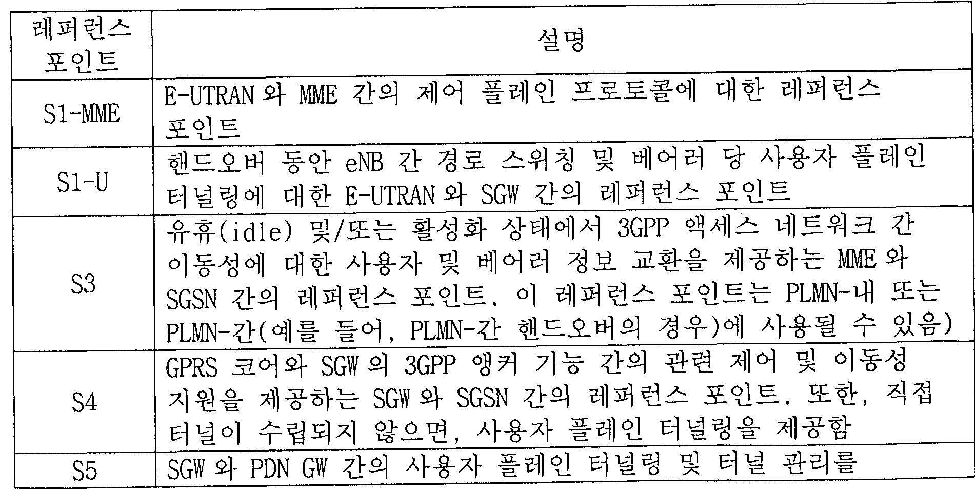
[88] 또한, 도 1에서는 다양한 레퍼런스 포인트들 (예를 들어, Sl-U, S1-麗 E등)을 도시한다. 3GPP 시스템에서는 E-UTRAN 및 EPC의 상이한 기능 개체 (functional entity)들에 존재하는 2 개의 기능을 연결하는 개념적인 링크를 레퍼런스 포인트 (reference point)라고 정의한다. 다음의 표 1은 도 1에 도시된 레퍼런스 포인트를 정리한 것이다. 표 1의 예시들 외에도 네트워크 구조에 따라 다양한 레퍼런스 포인트들이 존재할 수 있다.
[89] 【표 1】
Figure imgf000013_0001
Figure imgf000014_0001
[90] 도 1에 도시된 레퍼런스 포인트 중에서 S2a 및 S2b는 비 -3GPP 인터페이스에 해당한다. S2a는 신뢰되는 비— 3GPP 액세스 및 PDN GW 간의 관련 제어 및 이동성 지원을 사용자 플레인에 제공하는 레퍼런스 포인트이다. S2b는 ePDG 및 PDN GW 간의 관련 제어 및 이동성 지원을 사용자 플레인에 제공하는 레퍼런스 포인트이다.
[91] 도 2는 MTC 통신 모델의 예시들을 나타내는 도면이다.
[92] 3GPP GSM/UMTS/EPS에서는 MTC와 관련하여 PS 네트워크를 통한 통신을 정의하고 있지만, 본 발명은 PS 네트워크를 통한 MTC에 제한되는 것은 아니며 CS 네트워크를 통한 MTC에도 적용될 수 있다. 현재까지의 기술 표준에서는 네트워크 구조에 대한 정의는 3GPP 시스템의 기존 베어러를 이용하는 것이 제안되어 있다. 여기서, MTC 장치와 MTC 서버 간의 데이터 교환을 위해 SMS(Short Message Service)를 사용하는 방법이 제안되었다. 이는 MTC 애폴리케이션의 특성상 검침 정보나 제품 정보 등 적은 양의 디지털 데이터들이 그 대상이 될 것을 고려하여, 이에 가장 적절한 SMS를 이용하는 것이 제안되었고, 그 구체적인 방식으로는 기존의 SMS 방식과 IMS에 기반한 SMS 방식이 지원 가능하다. 또한, 이동성이 적은 MTC 애플리케이션을 위해 페이징 범위를 조정하는 방법들이 제안되고 있다.
[93] MTC 애플리케이션은 MTC 장치와 MTC 서버 (예를 들어 , SCS)에서 각각 실행되어 네트워크를 통한 통신을 통해 상호 동작한다. 이때, MTC 애플리케이션과 3GPP 네트워크 간의 통신에 무엇이 관여하는지에 따라 MTC 트래픽에 대한 다양한 모델이 구현될 수 있다. 도 2(a)는 MTC 서버 (예를 들어, SCS)없이 직접 통신이 수행되는 모델, 도 2(b)는 MTC 서버 (예를 들어, SCS)가 사업자 영역 (Operator domain)외부에 존재하는 모델, 도 2(c)는 MTC 서버 (예를 들어, SCS)가 사업자 영역 (Operator domain) 내부에 존재하는 경우를 나타낸 것이다. 또한, 도 2(a)는 3GPP 오퍼레이터의 제어를 받는 직접 통신 방식에 해당하고, 도 2(b)는 서비스 제공자에 의해서 제어되는 통신 방식에 해당하고, 도 2(c)는 3GPP 오퍼레이터에 의해서 제어되는 통신 방식을 해당한다. [94] 도 2(a)의 직접 모델은 MTC 애플리케이션이 3GPP 네트워크에 대해 0T(over- the-top) 애풀리케이션으로서 UE (또는 MTC 장치)와 직접 통신하는 것을 나타낸다.
[95] 도 2(b) 및 도 2(c)의 간접 모델은 3GPP 네트워크에 의해서 제공되는 부가적인 서비스를 이용하여 MTC 애플리케이션이 UE (또는 MTC 장치)와 간접적으로 통신하는 것을 나타낸다. 구체적으로, 도 2(b)의 예시에서는 MTC 애플리케이션이 서드 -파티 (즉, 3GPP에서 책임지지 않는) 서비스 제공자에 의해서 제공되는 부가 서비스들을 위해서 MTC 서버 (예를 들어, SCS)를 이용할 수 있다. MTC 서버 (예를 들어, SCS)는 3GPP 네트워크와 다양한 인터페이스를 통해서 통신할 수 있다. 한편, 도 2(c)의 예시에서는 MTC 애플리케이션이 3GPP 오퍼레이터 (곧 서비스 제공자에 해당함)에 의해서 제공되는 부가적인 서비스들을 위해서 MTC 서버 (예를 들어 , SCS)를 이용할 수 있다. MTC 서버 (예를 들어, SCS)와 3GPP 네트워크 간의 통신은 PL丽 내부에서 수행된다. 도 2(b) 및 도 2(c)에 있어서, MTC 서버 (예를 들어, SCS)와 MTC 애플리케이션 간의 인터페이스는 3GPP 표준에서 다루지 않는다.
[96] 한편, 도 2(b) 및 도 2(c)의 간접 모델은 상호 배타적이지 않고 보완적이므로, 3GPP 오퍼레이터가 상이한 애플리케이션을 위해 이들을 결합할 수도 있다. 즉, 도 2(d)처럼 직접 모델과 간접 모델이 동시에 사용되는 하이브리드 (hybrid) 모델로서 MTC 통신 모델이 구현될 수도 있다. 하이브리드 모델의 경우, MTC 장치는 HPL丽 내의 복수의 MTC 서버 (예를 들어, SCS)와 통신을 할 수 있고, 서비스 제공자에 의해 제어되는 MTC 서버 (예를 들어, SCS)와 3GPP 오퍼레이터에 의해 제어되는 MTC 서버 (예를 들어, SCS)에 있어서 MTC 애플리케이션들에게 제공되는 능력들 (Capabilities)이 다를 있다.
[97] 도 3은 MTC 구조의 예시적인 모델을 나타내는 도면이다.
[98] MTC를 위해서 사용되는 UE (또는 MTC 장치 )와 MTC 애플리케이션 간의 단-대- 단 애플리케이션은, 3GPP 시스템에 의해서 제공되는 서비스들과 MTC 서버 (예를 들어, SCS)에 의해서 제공되는 선택적인 서비스들을 이용할 수 있다. 3GPP 시스템은, MTC를 용이하게 하는 다양한 최쩍화를 포함하는 수송 및 통신 서비스들 (3GPP 베어러 서비스, IMS 및 SMS 포함)을 제공할 수 있다. 도 3에서는 MTC를 위해 사용되는 UE가 Um/Uu/LTE-Uu 인터페이스를 통하여 3GPP 네트워크 (UTRAN, E-UTRAN, GERAN, I-WLAN 등)으로 연결되는 것을 도시한다. 도 3의 구조 (architecture)는 상기 도 2와 관련하여 설명한 다양한 MTC 모델들을 포함한다. [99] 먼저, 도 3에서 도시하는 개체 (entity)들에 대하여 설명한다.
[100] 도 3에서 애플리케이션 서버는 MTC 애플리케이션이 실행되는 네트워크 상의 서버이며, MTC 애플리케이션 서버라고 할 수 있다. MTC 애플리케이션 서버에 대해서는 전술한 다양한 MTC 애플리케이션의 구현을 위한 기술이 적용될 수 있으며, 이에 대한 구체적인 설명은 생략한다. 또한, 도 3에서 MTC 애플리케이션 서버는 레퍼런스 포인트 API를 통하여 MTC 서버 (예를 들에 도 3의 예시에서 SCS)에 액세스할 수 있으며, 이에 대한 구체적인 설명은 생략한다. 또는, MTC 애플리케이션 서버는 MTC 서버 (예를 들어, SCS)와 함께 위치될 (col located) 수도 있다.
[101] MTC 서버 (예를 들어, SCS)는 MTC 장치를 관리하는 네트워크 상의 서버이며, 3GPP 네트워크에 연결되어 MTC를 위하여 사용되는 UE 및 PLMN의 노드들과 통신할 수 있다.
[102] MTC- 1 WF (MTC- 1 nt er Wor k i ng Function)는 MTC 서버와 오퍼레이터 코어 네트워크 간의 상호동작 (interworking)을 관장하고, MTC 동작의 프록시 (Proxy) 역할을 할 수 있다. MTC 간접 또는 하이브리드 모델을 지원하기 위해서, 하나 이상의 MTOIWF가 홈 PLMN HPL丽) 내에 존재할 수 있다. MTC-IWF는 레퍼런스 포인트 Tsp 상의 시그널링 프로토콜을 중계하거나 해석하여 PL丽에 특정 기능을 작동시킬 수 있다. MTC-IWF는, MTC 서버가 3GPP 네트워크와의 통신을 수립하기 전에 MTC 서버를 인증 (authenticate)하는 기능, MTC 서버로부터의 제어 플레인 요청을 인증하는 기능, 후술하는 트리거 지시와 관련된 다양한 기능 등을 수행할 수 있다ᅳ
[103] SMS-SC( Short Message Service-Service Cent er)/IP-SM-GW( Internet Protocol Short Message GateWay)는 단문서비스 (SMS)의 송수신을 관리할 수 있다. SMS-SC는 SME( Short Message Entity) (단문을 송신 또는 수신하는 개체)와 이동국 간의 단문을 중계하고 저장—및-전달하는 기능을 담당할 수 있다. IP-SM-CT는 IP 기반의 UE와 SMS— SC간의 프로토콜 상호동작을 담당할 수 있다.
[104] CDF(Charging Data Funct ion)/CGF(Charging Gateway Function)는 과금에 관련된 동작을 할 수 있다.
[105] HLR/HSS는 가입자 정보 (IMSI 등), 라우팅 정보, 설정 정보 등을 저장하고 MTC-IWF에게 제공하는 기능을 할 수 있다. [106] MSCCMobile Switching Center)/SGSN/醒 E는 UE의 네트워크 연결을 위한 이동성 관리, 인증, 자원 할당 등의 제어 기능을 수행할 수 있다. 후술하는 트리거링과 관련하여 MTC-IWF로부터 트리거 지시를 수신하여 MTC 장치에게 제공하는 메시지의 형태로 가공하는 기능을 수행할 수 있다.
[107] GGSN( Gat eway GPRS Support Node ) /S-GW ( Ser v i ng-Gat eway ) +P-GW ( Packe t Data Network-Gat eway)는 코어 네트워크와 외부 네트워크의 연결을 담당하는 게이트웨이 기능을 할 수 있다.
[108] 다음의 표 2는 도 3에서의 주요 레퍼런스 포인트를 정리한 것이다.
[109] 【표 2】
Figure imgf000017_0001
[110] 상기한 T5a, T5b, T5c 증 하나 이상의 레퍼런스 포인트를 T5라고 지칭할 수 있다.
[111] 한편, 간접 및 하이브리드 모델의 경우에 MTC 서버 (예를 들어, SCS)와의 사용자 플레인 통신, 및 직접 및 하이브리드 모델의 경우에 MTC 애플리케이션 서버와의 통신은, 레퍼런스 포인트 Gi 및 SGi를 통해서 기존의 프로토콜을 사용하여 수행될 수 있다.
[112] 도 2 내지 도 3에서 설명한 내용과 관련된 구체적인 사항은 3GPP TS 23.682 문서를 참조함으로써 본 문서에 병합될 수 있다 (incorporated by reference).
[113] NAS 레벨 흔잡 제어 [114] 일반적으로 네트워크가 제어할 수 있는 통신량의 한계를 넘어서는 경우를 네트워크 흔잡 (congest ion) 또는 과부하 (overload) 상태라고 할 수 있으며, 네트워크에 대한 송수신량을 조절하여 네트워크가 흔잡해지지 않도록 제어하는 것을 네트워크 흔잡 제어 (congestion control)라고 할 수 있다. 3GPP MTC 네트워크에서는, 네트워크에서 흔잡 /과부하가 발생한 경우에, UE와 코어 네트워크의 노드 (예를 들어, 匪 E, SGW, PDN-GW, MSC, SGSN, GGSN) 사이에서 NAS 레벨 흔잡 제어가 수행되고, 이에 따라 시그널링 흔잡이 회피 또는 제어될 수 있다.
[115] 이러한 NAS 레벨 흔잡 제어는, APN 기반의 흔잡 제어 (APN based congestion control)와 일반 NAS 레벨 이동성 관리 제어 (General NAS level mobility management control )≤. '구성된다.
[116] APN 기반의 흔잡 제어는, APN (즉, 흔잡 상태와 연관된 APN) 및 UE가 관련된 MM/SM(Mobi lity Management /Session Management ) 프로토콜 또는 EMM(EPS Mobility Management )/ESM(EPS Session Management ) 프로토콜에 따른 시그널링 흔잡 제어를 의미한다. 또한, APN 기반의 흔잡 제어는, APN 기반의 세션 관리 흔잡 제어 (APN based Session Management congestion control ) 및 APN 기반의 이동성 관리 혼잡 제어 (APN based Mobility Management congestion control)를 포함한다.
[117] 일반 NAS 레벨 이동성 관리 제어는, 일반적인 네트워크 흔잡이나 과부하 상황에서 UE가 요청하는 이동성 관리 시그널링 요청을, 코어 네트워크 노드 (예를 들어, 蘭 E, SGW, PDN-GW, MSC, SGSN, GGSN)가 거절 (reject)하여 흔잡 및 과부하를 회피하는 것을 의미한다.
[118] 일반적으로 코어 네트워크가 NAS 레벨 흔잡 제어를 수행하는 경우, UE에게 제공되는 거절 메시지 (reject message)에 대기 시간 (또는 확장된 대기 시간) 값이 포함될 수 있다. 이러한 대기 시간 값은 일정 범위 값 안에서 랜덤화 (randomize)되어 UE에게 제공된다. UE는 수신한 대기 타이머 값을 백오프 타이머 값으로 설정하여, 백오프 타이머가 만료 (expire)되기 전까지는 네트워크로 (E)匪 /(E)SM시그널링을 요청하지 않도톡 동작한다.
[119] (E)醒 시그널링은, 예를 들어, 어태치 요청, TAU/RAU 요청, 서비스 요청, 확장된 (extended) 서비스 요청 등을 포함한다. 또한, (E)SM 시그널링은, 예를 들어, PDN 연결성 (connectivity), 베어러 자원 할당 (Bearer Resource Allocation), 베어러 수정 (Bearer Modification), PDP 콘텍스트 활성화 (Packet Data Protocol Context Activation), PDP 콘텍스트 수정 (PDP Context Modification) 요청 등을 포함한다. 상기 백오프 타이머는 (E)匪 시그널링의 제어를 위한 匪 백오프 타이머와, (E)SM 시그널링의 제어를 위한 SM 백오프 타이머로 나눌 수 있다. 匪 백오프 타이머는 UE 별로 (per UE) 주어지고, SM 백오프 타이머는 관련된 APN 별로 (per associated APN) 및 UE별로 주어지며, 각각 독립적으로 동작한다.
[120] 추가적으로, 3GPP 네트워크에서 단말 (예를 들어, MTC 장치)은, "NAS 시그널링 낮은 우선순위 (NAS signaling low priority)' '를 가지도록, NAS 설정 M0를 통해서 설정 (configure)될 수 있다. NAS 시그널링 낮은 우선순위가 설정된 단말은 NAS 메시지 (예를 들어, 어태치 요청, TAU 요청, PDN 연결성 요청 등) 내에 낮은 우선순위를 셋팅하여 전송하게 된다.
[121] 일반적으로 코어 네트워크가 NAS 레벨 흔잡 제어를 수행하고 있는 경우에, 낮은 우선순위가 셋팅된 (예를 들어ᅤ NAS 시그널링 낮은 우선순위 지시자가 "단말이 NAS 시그널링 낮은 우선순위로 설정되었음 (UE/MS is configured for NAS signaling low priority)"으로 셋팅되는 경우) 단말에 대한 거절 메시지에 백오프 타이머 (또는 실행 대기 타이머 ) 값을 포함시켜 전송된다. 전술한 바와 같이, 백오프 타이머 값을 수신한 단말은, 백오프 타이머 (예를 들어, 丽 백오프타이머 및 /또는 SM 백오프 타이머)가 만료되기 전까지 네트워크에 (E)應 /(E)SM 시그널링을 요청하지 않도록 동작한다.
[122] 한편, 백오프 타이머가 동작중 (running)이더라도, 긴급한 서비스는 제공되어야 한다. 따라서, UE/MS가 높은 우선순위 (priority)를 갖는 서비스 사용자들과의 긴급 베어러 서비스 (emergency bearer service)를 이미 수행중이거나 또는 시작하려는 경우, 讓 /SM 백오프 타이머가 동작하고 있는 경우라도 해당 서비스 요청을 수행할 수 있다. 높은 우선순위를 갖는 서비스 사용자는, 예를 들어, 멀티미디어 우선순위 서비스 액세스 클래스 11-15를 가지고 네트워크에 액세스하는 사용자들일 수 있다. 또한, MT 호 (Mobile Terminated call)/SMS 서비스와 웅급 전화 (Emergency Call) 서비스를 수행하는 경우에도, 백오프 타이머 동작의 영향에 예외적인 상황으로 적용된다 (즉, 백오프 타이머가 동작중이더라도 해당 서비스가 제공될 수 있다).
[123] 다중 우선순위
[124] 현재 3GPP 표준 (Rel-10/Re卜 11) MTC 시스템 환경에서는 US/MS (이하에서는, "단말 "이라고 통칭함)에는 오직 2 가지의 우선순위, 즉, "(NAS 시그널링) 낮은 우선순위' '와 "(NAS 시그널링) 낮지 않은 (non-low) 우선순위" 중에서 하나 만이 설정될 수 있다. 예를 들어, NAS 시그널링 낮은 우선순위 지시자가 "단말이 NAS 시그널링 낮은 우선순위로 설정되었음 (UE/MS is configured for NAS signaling low priority)"으로 셋팅되거나, "단말이 NAS 시그널링 낮은 우선순위로 설정되지 않음 (UE/MS is not configured for NAS signaling low priority)"으로 셋팅될 수 있다.
[125] 그러나, 향후 애플리케이션 환경에 따라 2 이상의 다중 우선순위를 단말이 가질 수 있을 수 있다. 또한, 이러한 다중 우선순위는 장치 (또는 단말) 별로 설정되거나, 또는 애플리케이션 레벨 별로 설정될 수도 있다. 단말 별로 설정되는 우선순위와, 애플리케이션 별로 설정되는 우선순위는 별도로 (또는 독립적으로) 설정될 수 있다. 또한, 하나의 애플리케이션에 대해서도 복수개의 우선순위 중에서 하나가 설정될 수 있다.
[126] 기존의 무선 통신 시스템에서의 우선순위 관련 동작은 "낮은 우선순위"와 "낮지 않은 우선순위" 중 하나만을 가정하여 정의되어 있으므로 2 이상의 다중 우선순위가 설정되는 경우에는 올바르게 동작하지 못하는 문제가 발생한다. 따라서, 본 발명에서는 다중 우선순위가 설정되는 경우의 동작 방안, 우선순위가 변경되는 경우의 동작 방안 등에 대해서 제안한다.
[127] 이를 위하여, 다중 우선순위를 갖는 단말이 PDN 연결을 수립 (establish)할 때마다 그 시점에서 장치 별로 혹은 애플리케이션 레벨 별로 상이한 우선순위를 셋팅하여 PDN 연결을 수립할 수 있도톡 하기 위해서는, 이러한 다중 우선순위를 갖는 단말의 PDN 연결 수립 방법에 대한 추가적인 보완이 필요하다.
[128] '만약, 이전에 수립된 PDN 연결이 낮은 우선순위를 갖는 PDN 연결이었지만, 새롭게 장치 별로 혹은 애플리케이션 레벨에 따라서 상이한 우선순위로 변경된 경우에는, 새롭게 수립되는 PDN 연결의 경우에는 변경된 우선순위를 적용하게 된다. 이 경우, 이전에 수립되어 있는 PDN 연결을 어떻게 처리해야 할지가 불명료한 문제가 발생한다. 예를 들어, 이전에 셋팅되어 있는 우선순위를 갖는 PDN 연결을 그대로 유지할지, 아니면, 이전에 셋팅되어 있는 우선순위를 갖는 PDN 연결을 해제하고 새톱게 변경된 우선순위를 적용하여 PDN 연결을 재 -수립 (reestablish)할지가 명확하게 결정될 수 있도록, 우선순위 변경에 따른 PDN 연결 방안이 마련되어야 한다. [129] 또한, 전술한 바와 같이, 단말에 匪 백오프 타이머와 SM 백오프 타이머가 각각 또는 동시에 동작하고 있는 상황에서, 해당 단말은 네트워크에게 (E)MM 관련 시그널링 및 /또는 (E)SM 관련 시그널링 요청을 하지 못하도록 되어 있다. 다만, 긴급 콜 /서비스 또는 멀티미디어 우선순위 서비스를 사용하는 경우에는, 백오프 타이머가 동작하더라도 단말이 관련 절차를 수행할 수 있다.
[130] 만약, 단말 별로 또는 애플리케이션 레벨 별로 다중 우선순위를 가지는 단말의 경우에는, 우선순위가 변경된 경우에 匪 백오프 타이머 및 /또는 SM 백오프 타이머 (이하, "MM/SM 백오프 타이머' '라고 표현함)에 기초한 동작을 어떻게 수행할지가 불명료하다는 문제가 발생한다. 예를 들어, 우선순위가 변경된 경우에 기존의 應 /SM 백오프 타이머를 중지할지 아니면 기존의 MM/SM 백오프 타이머를 그대로 유지할지가 명확하게 결정될 수 있도록, 우선순위 변경에 따른 백오프 타이머 처리 방안이 마련되어야 한다.
[131] 요컨대, 다중 우선순위를 갖는 단말의 경우에 우선순위 변경에 따라서 PDN 연결을 어떻게 처리할 지와, 네트워크 흔잡 상황으로 인하여 MM/SM 백오프 타이머가 동작 중인 경우에 우선순위 변경에 따라서 동작 중인 MM/SM 백오프 타이머를 어떻게 처리할 것인지가 불명확하다는 문제가 있으므로, 결국 PDN 연결 제어 및 /또는 NAS 레벨 흔잡 제어를 올바르게 또는 효율적으로 수행하지 못할 수 있다. 이러한 경우, 네트워크 상황, 서비스 연결성 및 사용자 경험이 더욱 악화된다. 따라서, 2 레벨 이상의 다중 우선순위가 적용되고 및 /또는 우선순위가 변경되는 경우에, PDN 연결 및 應 /SM 백오프 타이머를 처리하는 새로운 방안이 요구된다.
[132] 다중 우선순위 적용에 따른 개선된 NAS 레벨 동작
[133] 전술한 바와 같이 MTC는 일반적으로 많은 개수의 단말과 네트워크간의 통신을 수반하고, 각각의 단말에 대한 데이터의 양은 비교적 적고 긴급하지 않은 정보인 경우 (예를 돌어, 검침 결과의 보고 등)를 가정할 수 있다. 따라서, MTC 단말에 대한 우선순위는 낮은 우선순위로 설정되는 것이 일반적이다.
[134] 2 레벨 우선순위 (또는 듀얼 (dual) 우선순위 )가 적용되는 경우에 대한 본 발명의 예시들에 대해서 이하에서 설명한다. 여기서 듀얼 우선순위는, 예를 들어, NAS 시그널링 낮은 우선순위 지시자가 "단말이 NAS 시그널링 낮은 우선순위로 설정되었음 (UE/MS is configured for NAS signaling low priority)"으로 셋팅되거나 (이하, "low priority"라고 표현함), 또는 "단말이 NAS 시그널링 낮은 우선순위로 설정되지 않음 (UE/MS is not configured for NAS signaling low priority)' '으로 셋팅될 수 있음 (이하, "not low priority"라고 표현함)을 의미한다. 그러나, 본 발명의 범위가 듀얼 우선순위가 적용되는 경우만으로 제한되지는 않고, 다중 우선순위가 적용되는 경우도 포함한다.
[135] 듀얼 우선순위 기능을 고려한 종래의 세션 관리 방법은, 특정 APN에 대해서 SM 백오프 타이머가 동작중인 경우에 SM 관련 시그널링 (예를 들어, PDN 연결성 , 베어러 자원 할당ᅵ 베어러 수정, PDP 콘텍스트 활성화, PDP 콘텍스트 수정 요청 등)을 금지하는 방안에 대해서 주로 다루었다.
[136] 한편, 단말이 어태치 과정 동안에 APN에 대한 여하한 정보도 제공하지 않았는데, 상기 단말의 NAS 요청이 네트워크 노드에 의해서 거절되면서 SM 백오프 타이머가 설정되는 경우를 가정할 수 있다. 즉, SM 백오프 타이머가 특정 APN에 대해서 설정되는 것이 아니라, APN 없이 설정될 수 있다.
[137] 예를 들어, 어태치 요청 메시지에는 APN 없이 (without APN) PDN 연결을 요청하는 정보를 피기백 (piggyback)해서 보낼 수 있다 (이를 "APN 없는 어태치 요청' '을 전송한다고 표현할 수 있음). 만약, low priority 단말이 APN 없는 어태치 요청을 네트워크 노드 (예를 들어, MME)로 전송하는 경우, 상기 네트워크 노드는 해당 단말에 대해서 PDN 연결이 설정될 APN (여기서, 단말은 APN 없이 PDN 요청을 수행했지만, 네트워크 노드는 가입자 정보 등의 정보에 기초해서 상기 PDN 요청에 대한 APN (예를 들어, 상기 단말에 대한 디폴트 APN)을 특정할 수 있음)이 흔잡 상태인 경우에는, SM 백오프 타이머를 상기 단말에게 설정하여 줄 수 있다. 여기서, SM 백오프 타이머는 특정 APN에 대해서 설정되는 것이 아니고, APN 없이 (without APN) 설정되는 SM 백오프 타이머이다. 이 경우, 단말의 입장에서는 SM 백오프 타이머만이 설정되고, MM 백오프 타이머가 설정된 것은 아니다. 이러한 경우에, 상기 낮은 우선순위 지시자가 low priority 또는 not low priority 로 설정되는지에 따라서, 醒 시그널링 (예를 들어, APN 없는 어태치 요청 )의 전송이 허용되는지 여부가 종래기술에서는 명확하게 정의된 바 없다.
[138] 구체적으로, 종래기술에 따르면 단말이 네트워크 노드로 전송한 SM 시그 ^링 (예를 들어, PDN 연결성 요청 등)이 "자원 불층분 "을 이유로 거절되면서 그 거절 메시지에 SM 백오프 타이머 (예를 들어 , T3396) 정보요소 (IE)가 포함된 경우에 단말의 동작을 다음과 같이 정의하고 있다. [139] - 어태치 요청과 함께 PDN 연결성 요청이 전송되는 경우, 단말은 SM 백오프 타이머의 수신된 값 및 어태치 거절 메시지에 대한 무결성 (integrity) 보호에 따라서 다음과 같은 상이한 동작을 수행한다.
[140] 만약 어태치 거절 메시지가 무결성 보호되지 않는 경우에는, 단말은 SM 백오프 타이머가 동작중이면 이를 중지 (stop)시키고, 그리고 나서 소정의 범위 내의 임의의 값으로 상기 SM 백오프 타이머를 시작 (start)한다.
[141] 만약 어태치 거절 메시지가 무결성 보호되는 경우에, SM 백오프 타이머 값이 0도 아니고 비활성화되지도 않은 경우라면, 단말은 SM 백오프 타이머가 동작중이면 이를 중지시키고, 상기 SM 백오프 타이머 IE에 의해서 제공되는 값으로 SM 백오프 타이머를 시작한다. 그리고, 단말이 어태치 과정 동안에 여하한 APN을 제공하지 않은 경우라면, SM 백오프 타이머가 만료 (expire)하기 전까지는, 단말은 APN 없는 새로운 어태치 과정을 시작하는 것이 금지된다.
[142] 요컨대, 단말이 APN 없는 어태치 요청을 네트워크로 전송했는데, 상기 어태치 요청이 거절되면서 단말에게 SM 백오프 타이머가 설정된 경우, 단말은 醒 백오프 타이머가 설정된 것이 아니더라도 새로운 어태치 요청을 전송할 수 없다. 이러한 상황에서, 이중 우선순위가 설정되는 단말의 경우에는 low priority 또는 not low priority에 따라서 새로운 어태치 요청의 전송을 허용할지 금지할지 여부가 전혀 정의된 바 없다.
[143] 이에 따라, 네트워크 흔잡을 감소하기 위한 백오프 타이머의 설정과, 중요한 시그널링의 전송이라는 두 가지 측면에서 단말 동작의 불명료성으로 인하여 전체적인 시스템 성능의 저하가 우려된다.
[144] 이를 해결하기 위한 본 발명의 실시예들에 대해서 이하에서 설명한다:
[145] 먼저 NAS 시그널링에 대한 낮은 우선순위 지시를 다루는 방안에 대해서 설명한다.
[146] 단말은 NAS 메시지에 디바이스 특성 (propert ies)이라는 정보요소 (IE)를 포함시키고 해당 단말이 NAS 시그널링 low priority로 설정된 것으로 낮은 우선순위 지시자를 셋팅함으로써, 자신이 low priority로 설정된 것임을 지시 (indicate)할 수 있다. 한편, 다음과 같은 경우에는 단말은 낮은 우선순위 지시자를 not low priority로 설정하게 된다:
[147] - 단말이 긴급 베어러 서비스를 위해서 어태치를 수행하는 경우; [148] - 단말이 긴급 베어러 서비스의 수립을 위한 PDN 연결을 가지고 있으며 EPS 丽 과정을 수행 중인 경우, 또는 긴급 베어러 서비스를 위한 PDN 연결을 수립 중인 경우;
[149] - 이중 우선순위가 설정된 단말이, 상위 계층에 의해서 not low priority로 셋팅된 낮은 우선순위 지시자를 가지는 PDN 연결을 수립하도록 요청되는 경우;
[150] - 이중 우선순위가 설정된 단말이, not low priority로 셋팅된 낮은 우선순위 지시자를 가지고 수립된 PDN 연결에 관련된 EPS SM 과정을 수행 중인 경우;
[151] - 이중 우선순위가 설정된 단말이, 낮은 우선순위 지시자를 not low priority 로 셋팅하여 수립된 PDN 연결을 가지고 있으며 EPS 丽 과정을 수행중인 경우;
[152] - 단말이 액세스 클래스 11 내지 15를 가지고 네트워크에 액세스하는 경우; 또는
[153] - 단말이 페이징에 웅답하는 경우.
[154] 네트워크는 NAS 레벨 醒 흔잡 제어 및 APN 기반 흔잡 제어를 위해서, NAS 시그널링 낮은 우선순위 지시를 사용할 수 있다.
[155] NAS 시그널링 낮은 우선순위 지시가 PDN 연결성 요청 (PDN CONNECTIVITY REQUEST) 메시지에 포함되는 경우, 醒 E는 PDN 연결성 요청 과정에 의해서 활성화 (activate)된 디폴트 EPS 베어러 콘텍스트 내에 상기 NAS 시그널링 낮은 우선순위 지시를 저장한다.
[156] 다음으로, 이중 우선순위가 설정된 단말에 대한 SM 요청을 다루는 방안에 대해서 설명한다.
[157] 먼저 본 발명의 APN 없는 SM 백오프 타이머가 설정되는 경우에 대한 단말의 동작에 대해서 설명하기에 앞서, 특정 APN에 대한 SM 백오프 타이머가 설정되는 경우에 대해서 설명한다.
[158] 특정 APN에 대한 SM 백오프 타이머 (예를 들어, T3396)가 동작중인 경우인데, low priority로 설정된 낮은 우선순위 지시자를 포함하는 PDN 연결성 요청, 베어러 자원 수정 요청 또는 베어러 자원 할당 요청 메시지가 "자원 부족 (insufficient resources)"을 이유로 거절되면서 상기 SM 백오프 타이머가 설정된 것인 경우, 상위 계충의 요청에 따라서 단말은: [159] - 낮은 우선순위 지시자를 not low priority 로 셋팅하여, 동일한 APN으로 PDN연결성 요청 메시지를 전송할 수 있다; 또는
[160] - 낮은 우선순위 지시자가 not low priority로 셋팅되어 수립된 PDN 연결이 존재하는 경우에는, 해당 PDN 연결에 대한 베어러 자원 수정 요청 또는 베어러 자원 할당 요청 메시지를 보내는데, 이 때 낮은 우선순위 지시자는 not low priority로 설정된다.
[161] 한편, APN 없는 SM 백오프 타이머가 설정되는 경우에 대한 본 발명의 제안사항에 따르면 단말은 다음과 같이 동작한다.
[162] APN 없는 SM 백오프 타이머가 동작중인 경우인데, low priority로 설정된 낮은 우선순위 지시자를 포함하는 어태치 요청 메시지와 함께 전송되는 PDN 연결성 요청 메시지가 "자원 부족 (insufficient resources)' '을 이유로 거절되면서 상기 SM 백오프 타이머가 설정된 것인 경우, 상위 계층의 요청에 따라서 단말은 not low priority로 설정된 낮은 우선순위 지시자를 가지는 APN 없는 새로운 어태치 과정올 개시할 수 있다.
[163] 즉, APN 없는 어태치 요청과 함께 전송되는 PDN 연결성 요청이 거절되면서 SM 백오프 타이머가 설정된 경우라면, 새로운 어태치 요청 메시지 (즉, APN 없는 어태치 요청 메시지)는, low priority로 셋팅된 경우에는 전송되지 못하고, not low priority로 셋팅된 경우에는 전송될 수 있다고 표현할 수도 있다.
[164] 이에 따라, SM 백오프 타이머가 동작 중에는 low priority인 APN 없는 어태치 요청의 전송을 금지함으로써 네트워크 흔잡의 가중을 방지할 수 있고, 한편으로는 not low priority인 새로운 어태치 요청의 전송을 허용함으로써 긴급 /중요한 시그널링을 보호할 수 있으므로, 단말의 동작이 명확하게 되고 시스템 전체 성능이 개선될 수 있다. 예를 들어, 단말과 네트워크 간의 불필요한 서비스 지연 /통신 지연을 방지하고, 네트워크 자원이 불필요하게 낭비되는 것을 방지할 수 있다.
[165] 이와 유사하게, PDP 콘텍스트 활성화 요청 (ACTIVATE PDP CONTEXT REQUEST) 메시지와 관련한 SM요청에 대해서도, 본 발명의 제안사항이 적용될 수 있다.
[166] 먼저 본 발명의 APN 없는 SM 백오프 타이머가 설정되는 경우에 대한 단말의 동작에 대해서 설명하기에 앞서, 특정 APN에 대한 SM 백오프 타이머가 설정되는 경우에 대해서 설명한다. [167] 특정 APN에 대해서 SM 백오프 타이머가 동작 중인데, low priority로 설정된 낮은 우선순위 지시자를 포함하는 PDP 콘텍스트 활성화 요청, 세컨더리 PDP 콘텍스트 활성화 요청 (ACTIVATE SECONDARY PDP CONTEXT REQUEST) 또는 PDP 콘텍스트 수정 요청 (MODIFY PDP CONTEXT REQUEST) 메시지가 "자원 부족 (insufficient resources)"을 이유로 거절되면서 상기 SM 백오프 타이머가 설정된 것인 경우, 상위 계층의 요청에 따라서 단말은:
[168] - 낮은 우선순위 지시자를 not low priority 로 셋팅하여, 동일한 APN으로 PDP 콘텍스트 활성화 요청 메시지를 전송할 수 .있다; 또는
[169] - 낮은 우선순위 지시자가 not low priority 로 셋팅되어 수립된 활성 PDP 콘텍스트가 존재하는 경우에는, 해당 PDN 콘텍스트에 대한 세컨더리 PDP 콘텍스트 활성화 요청 또는 PDP 콘텍스트 수정 요청 메시지를 전송하는데, 이 때 낮은 우선순위 지시자는 not low priority로 설정된다.
[170] 한편, APN 없는 SM 백오프 타이머가 설정되는 경우에 대한 본 발명의 제안사항에 따르면 단말은 다음과 같이 동작한다.
[171] APN 없는 SM 백오프 타이머가 동작중인 경우인데, low priority로 설정된 낮은 우선순위 지시자를 포함하는 PDP 콘텍스트 활성화 요청 메시지가 "자원 부족 (insufficient resources)' '을 이유로 거절되면서 상기 SM 백오프 타이머가 설정된 것인 경우, 상위 계층의 요청에 따라서 단말은 not low priority로 설정된 낮은 우선순위 지시자를 가지는, APN 없는 PDP 콘텍스트 활성화 요청 메시지를 전송할 수 있다.
[172] 즉, APN 없는 PDP 콘텍스트 활성화 요청이 거절되면서 SM 백오프 타이머가 설정된 경우라면, 새로운 PDP 콘텍스트 활성화 요청 (즉, APN 없는 PDP 콘텍스트 활성화 효청 메시지)는, low priority로 셋팅된 경우에는 전송되지 못하고, not low priority 로 셋팅된 경우에는 전송될 수 있다고 표현할 수도 있다.
[173] 이에 따라, SM 백오프 타이머가 동작 중에는 low priority인 APN 없는 PDP 콘텍스트 활성화 요청의 전송을 금지함으로써 네트워크 흔잡의 가중을 방지할 수 있고, 한편으로는 not low priority인 새로운 APN 없는 PDP 콘텍스트 활성화 요청의 전송을 허용함으로써 긴급 /중요한 시그널링을 보호할 수 있으므로, 단말의 동작이 명확하게 되고 시스템 전체 성능이 개선될 수 있다. 예를 들어 단말과 네트워크 간의 불필요한 서비스 지연 /통신 지연을 방지하고, 네트워크 자원이 불필요하게 낭비되는 것을 방지할 수 있다. [174] 추가적으로, 단말이 3 레벨 이상의 다증 -레벨 우선순위를 가지는 경우, 우선순위 레벨에 따라서 MM 백오프 타이머 및 /또는 SM 백오프 타이머를 설정 받을 수 있다. MM/SM 백오프 타이머를 적용 받는 우선순위 (예를 들어, 다중 -레벨 우선순위 중 낮은 하나 이상의 우선순위)의 경우, PDN 연결성 요청 메시지를 단독으로 전송하거나, PDN 연결성 요청과 함께 어태치 요청 메시지를 전송하거나, PDP 콘텍스트 활성화 요청 메시지를 전송할 때, 應 /SM 백오프 타이머에 의한 흔잡 제어의 적용을 받게 된다. 예를 들어, 백오프 타이머가 동작중에는 해당 NAS 요청을 수행할 수 없다.
[175] 한편 MM/SM 백오프 타이머를 적용 받지 않는 우선순위 (예를 들어 다중- 레벨 우선순위 중 높은 하나 이상의 우선순위)의 경우, PDN 연결성 요청을 단독으로 전송하거나, PDN 연결성 요청과 함께ᅳ 어태치 요청 메시지를 전송하거나, PDP 콘텍스트 활성화 요청 메시지를 전송할 때, 匪 /SM 백오프 타이머에 의한 흔잡 제어의 적용을 받지 않는다. 예를 들어, 백오프 타이머가 동작중이더라도 해당 NAS 요청을 수행할 수 있다.
[176] 도 4는 본 발명의 일례에 따른 백오프 타이머 제어 방법을 설명하기 위한 도면이다.
[177] 단계 S410에서 단말은 제 1 우선순위 레벨 (예를 들어, 낮은 우선순위 레벨)로 셋팅된, APN 없는 NAS 요청 (예를 들어, APN 없는 어태치 요청)을 네트워크로 전송할 수 있다.
[178] 단계 S420에서 네트워크쟈 흔잡 (또는 자원 불층분)인 경우에는 상기 NAS 요청에 대한 거절 메시지를 상기 단말이 상기 네트워크로부터 수신할 수 있다. 여기서, 거절 메시지에는 SM 백오프 정보가 포함될 수 있다.
[179] 단계 S430에서 단말은 SM 백오프 타이머를 시작할 수 있다.
[180] 단계 S440에서는 SM 백오프 '타이머 동작 중에 단말이 새로운 NAS 요청을 전송 (예를 들어, 새로운 어태치 과정을 개시)하려고 할 때, 그 새로운 NAS 요청이 제 1 우선순위로 설정된 것인지 판정할 수 있다.
[181] 단계 S440의 결과가 YES인 경우 (즉, 제 1 우선순위 (또는 낮은 우선순위)로 설정된 경우), 단계 S450으로 진행하예 단말은 SM 백오프 타이머 동작 증에는 상기 새로운 NAS 요청을 전송하는 것이 허용되지 않는다. [182] 단계 S440의 결과가 NO인 경우 (즉, 제 1 우선순위 (또는 낮은 우선순위)로 설정되지 않은 경우), 단계 S460으로 진행하여, 단말은 SM 백오프 타이머 동작 중에도 상기 새로운 NAS 요청 전송하는 것이 허용된다.
[183] 도 4를 참조하여 설명한 본 발명의 백오프 타이머 제어 방법에 있어서, 전술한 본 발명의 다양한 실시예들에서 설명한 사항들은 독립적으로 적용되거나 또는 2 이상의 실시예가 동시에、 적용될 수 있다.
[184] 또한, 전술한 본 발명의 예시들은 MTC 방식의 무선 통신 서비스에 대해서 적용되는 것을 예시적으로 설명하였지만, 본 발명에서 제안하는 원리는 일반적인 무선 통신 시스템에서 다중 우선순위에 따른 동작, 백오프 타이머의 제어 동작 등에 대해서도 동일하게 적용될 수 있다.
[185] 전술한 본 발명의 실시예들에 따르면, 단말과 네트워크간의 서비스 /통신에 있어서의 불필요한 지연을 방지할 수 있고, 이에 따라 네트워크 자원 불필요한 낭비를 막을 수 있으며, 결과적으로 사용자 경험 (user experience)을 향상시킬 수 있다.
[186] 도 5는 본 발명의 일례에 따른 무선 장치에 대한 바람직한 실시예의 구성을 도시한 도면이다.
[187] 도 6을 참조하여 본 발명에 따른 무선 장치 (1000)는, 송수신모들 (1010), 프로세서 (1020) 및 메모리 (1030)를 포함할 수 있다. 송수신모들 (1010)은 외부 장치 (예를 들어, 네트워크 노드, 단말, 서버 등)로 각종 신호, 데이터 및 정보를 송신하고, 외부 장치 (예를 들어, 네트워크 노드, 단말 서버 등)로 각종 신호, 데이터 및 정보를 수신하도록 구성될 수 있다ᅳ 프로세서 (1020)는 무선 장치 (1000) 전반의 동작을 제어할 수 있으며 , 무선 장치 (1000)가 외부 장치와 송수신할 정보 둥을 연산 처리하는 기능을 수행하도록 구성될 수 있다. 메모리 (1030)는 연산 처리된 정보 등을 소정시간 동안 저장할 수 있으며 , 버퍼 (미도시 ) 등의 구성요소로 대체될 수 있다.
[188] 본 발명의 일 실시예에 따른 무선 장치 (1000)는 다중 우선순위가 설정된 경우에 백오프 타이머를 제어하도록 동작할 수 있다. 프로세서 (1020)는, 제 1 우선순위 레벨 (예를 들어, 낮은 우선순위)로 셋팅되고, APN없는 NAS 요청 메시지 (예를 들어, APN 없는 어태치 요청 메시지)를 상기 송수신 모들 (1010)을 이용하여 네트워크 노드로 전송하도록 설정될 수 있다. 또한, 프로세서 (1020)는, 네트워크 노드로부터 상기 NAS 요청 메시지에 대한 거절 메시지를 상기 송수신 모들 (1010)을 이용하여 수신하도록 설정될 수 있다. 또한, 프로세서 ( ^ 는 상기 거절 메시지에 기초하여 s½ 백오프 타이머를 시작하도록 설정될 수 있다. 또한, 프로세서 (1020)는, 상기 SM 백오프 타이머가 동작하는 중에, 상기 제 1 우선순위 레벨로 셋팅되지 않은 (또는 낮은 우선순위로 설정되지 않은) 새로운 NAS 요청 메시지가 전송되는 것을 허용하도록 설정될 수 있다. 또한, 프로세서 (1020)는, 상기 SM 백오프 타이머가 동작하는 중에, 상기 제 1 우선순위 레벨로 셋팅된 (또는 낮은 우선순위로 설정된) 새로운 NAS 요청 메시지가 전송되는 것을 허용하지 않도록 설정될 수 있다.
[189] 위와 같은 무선 장치 (1000)의 구체적인 구성은, 전술한 본 발명의 다양한 실시예에서 설명한 사항들이 독립적으로 적용되거나 또는 2 이상의 실시예가 동시에 적용되도톡 구현될 수 있으며, 중복되는 내용은 명확성을 위하여 설명을 생략한다.
[190] 상술한 본 발명의 실시예들은 다양한 수단을 통해 구현될 수 있다. 예를 들어, 본 발명의 실시예들은 하드웨어, 펌웨어 (firmware), 소프트웨어 또는 그것들의 결합 등에 의해 구현될 수 있다.
[191] 하드웨어에 의한 구현의 경우, 본 발명의 실시예들에 따른 방법은 하나 또는 그 이상의 ASICsCAppl ication Specific Integrated Circuits) , DSPs(Digital Signal Processors) , DSPDs(Digital Signal Processing Devices) , PLDs (Programmable Logic Devices) , FPGAs(Field Programmable Gate Arrays) , 프로세서., 컨트를러, 마이크로 컨트를러, 마이크로 프로세서 등에 의해 구현될 수 있다.
[192] 펌웨어나 소프트웨어에 의한 구현의 경우, 본 발명의 실시예들에 따른 방법은 이상에서 설명된 기능 또는 동작들을 수행하는 모큘, 절차 또는 함수 등의 형태로 구현될 수 있다. 소프트웨어 코드는 메모리 유닛에 저장되어 프로세서에 의해 구동될 수 있다. 상기 메모리 유닛은 상기 프로세서 내부 또는 외부에 위치하여, 이미 공지된 다양한 수단에 의해 상기 프로세서와 데이터를 주고 받을 수 있다.
[193] 상술한 바와 같이 개시된 본 발명의 바람직한 실시예들에 대한 상세한 설명은 당업자가 본 발명올 구현하고 실시할 수 있도록 제공되었다. 상기에서는 본 발명의 바람직한 실시예들을 참조하여 설명하였지만, 해당 기술 분야의 숙련된 당업자는 본 발명의 영역으로부터 벗어나지 않는 범위 내에서 본 발명을 다양하게 수정 및 변경시킬 수 있음을 이해할 수 있을 것이다. 예를 들어, 당업자는 상술한 실시예들에 기재된 각 구성을 서로 조합하는 방식으로 이용할 수 있다. 따라서ᅳ 본 발명은 여기에 나타난 실시형태들에 제한되려는 것이 아니라, 여기서 개시된 원리들 및 신규한 특징들과 일치하는 최광의 범위를 부여하려는 것이다.
[194] 본 발명은 본 발명의 정신 및 필수적 특징올 벗어나지 않는 범위에서 다른 특정한 형태로 구체화될 수 있다. 따라서, 상기의 상세한 설명은 모든 면에서 제한적으로 해석되어서는 아니 되고 예시적인 것으로 고려되어야 한다. 본 발명의 범위는 첨부된 청구항의 합리적 해석에 의해 결정되어야 하고, 본 발명의 등가적 범위 내에서의 모든 변경은 본 발명의 범위에 포함된다. 본 발명은 여기에 나타난 실시형태들에 제한되려는 것이 아니라, 여기서 개시된 원리들 및 신규한 특징들과 일치하는 최광의 범위를 부여하려는 것이다. 또한, 특허청구범위에서 명시적인 인용 관계가 있지 않은 청구항들을 결합하여 실시예를 구성하거나 출원 후의 보정에 의해 새로운 청구항으로 포함할 수 있다.
【산업상 이용가능성】
[195] 상술한 바와 같은 본 발명의 실시형태들은 다양한 이동통신 시스템에 적용될 수 있다.

Claims

【청구의 범위】
【청구항 11
다중 우선순위가 설정된 단말에서 백오프 타이머를 제어하는 방법에 있어서, 제 1 우선순위 레밸로 셋팅되고, APN(Access Point Name) 없는 NAS(Non Access Stratum) 요청 메시지를 네트워크 노드로 전송하는 단계;
상기 네트워크 노드로부터 상기 NAS 요청 메시지에 대한 거절 메시지를 수신하는 단계 ; 및
상기 거절 메시지에 기초하여 세션 관리 (SM) 백오프 타이머를 시작하는 단계를 포함하고,
상기 SM 백오프 타이머가 동작하는 중에, 상기 제 1 우선순위 레벨로 셋팅되지 않은 새로운 NAS 요청 메시지를 상기 단말이 전송하는 것이 허용되는, 백오프 타이머 제어 방법 .
【청구항 2】 - 제 1 항에 있어서,
상기 SM 백오프 타이머가 동작하는 중에, 상기 제 1 우선순위 레밸로 셋팅된 새로운 NAS 요청 메시지를 상기 단말이 전송하는 것은 허용되지 않는, 백오프 타이머 제어 방법.
【청구항 3】
제 2 항에 있어서,
상기 단말은 상기 NAS 요청 메시지의 전송을 통해 개시되는 과정 중에 APN을 제공하지 않았던, 백오프 타이머 제어 방법.
【청구항 4]
제 3 항에 있어서,
상기 NAS 요청 메시지의 전송을 통해 개시되는 과정은 어태치 과정인, 백오프 타이머 제어 방법 .
【청구항 5】
제 1 항에 있어서,
상기 APN 없는 NAS 요청 메시지는, APN 없는 어태치 요청 메시지인, 백오프 타이머 제어 방법.
【청구항 6】
제 1 항에 있어서, 상기 APN 없는 NAS 요청 메시지는 APN 없는 PDN(Packet Data Network) 연결성 요청 (PDN CONNECTIVITY REQUEST)과 함께 전송되는 어태치 요청 메시지인, 백오프 타이머 제어 방법 .
【청구항 7】
제 1 항에 있어서,
상기 거절 메시지는 상기 SM 백오프 타이머에 대한 값을 포함하는, 백오프 타이머 제어 방법.
【청구항 8]
제 1 항에 있어서,
상기 거절 메시지는 자원 불층분 ( insufficient resources)을 이유로 거절되는, 백오프 타이머 제어 방법.
【청구항 9】
제 1 항에 있어서,
상기 다중 우선순위가 설정된 단말은, 이중 (dual) 우선순위가 설정된 단말인, 백오프 타이머 제어 방법 .
【청구항 10】
제 9 항에 있어서 ,
상기 제 1 우선순위 레벨은 상기 단말이 NAS(Non Access Stratum) 시그널링 낮은 우선순위 (low priority)로 설정된 것에 해당하는, 백오프 타이머 제어 방법.
【청구항 11】·
제 9 항에 있어서,
상기 제 1 우선순위. 레벨은, 낮은 우선순위 지시자 (low priority indicator)가 상기 단말이 NAS 시그널링 낮은 우선순위로 설정된 것으로 셋팅되는 것에 해당하는, 백오프 타이머 제어 방법.
【청구항 12】
제 1 항에 있어서,
상기 단말은 MTC 장치 (Machine Type Communication device)인, 백오프 타이머 제어 방법.
【청구항 13】
다중 우선순위가 설정된 경우에 백오프 타이머를 제어하는 단말 장치에 있어서, 송수신 모들; 및
프로세서를 포함하며,
상기 프로세서는:
제 1 우선순위 레벨로 셋팅되고, APN(Access Point Name) 없는 NAS(Non Access Stratum) 요청 메시지를 상기 송수신 모들을 이용하여 네트워크 노드로 전송하고;
상기 네트워크 노드로부터 상기 NAS 요청 메시지에 대한 거절 메시지를 상기 송수신 모들을 이용하여 수신하고;
상기 거절 메시지에 기초하여 세션 관리 (SM) 백오프 타이머를 시작하도톡 설정되며,
상기 SM 백오프 타이머가 동작하는 중에, 상기 제 1 우선순위 레벨로 셋팅되지 않은 새로운 NAS 요청 메시지를 상기 단말이 전송하는 것이 허용되는, 백오프 타이머 제어 단말 장치 .
PCT/KR2013/008877 2012-10-05 2013-10-04 무선 통신 시스템에서 다중 우선순위 제어 방법 및 장치 WO2014054905A1 (ko)

Priority Applications (7)

Application Number Priority Date Filing Date Title
KR1020167009007A KR20160044048A (ko) 2012-10-05 2013-10-04 무선 통신 시스템에서 다중 우선순위 제어 방법 및 장치
EP13843503.7A EP2905990B1 (en) 2012-10-05 2013-10-04 Method and device for controlling multipriority in wireless communication system
CN201380052339.XA CN104704875B (zh) 2012-10-05 2013-10-04 在无线通信系统中控制多优先级的方法和装置
KR1020157007452A KR101611965B1 (ko) 2012-10-05 2013-10-04 무선 통신 시스템에서 다중 우선순위 제어 방법 및 장치
US14/432,417 US9554233B2 (en) 2012-10-05 2013-10-04 Method and device for controlling multipriority in wireless communication system
US15/375,918 US9894465B2 (en) 2012-10-05 2016-12-12 Method and device for controlling multipriority in wireless communication system
US15/872,413 US10779142B2 (en) 2012-10-05 2018-01-16 Method and device for controlling multipriority in wireless communication system

Applications Claiming Priority (2)

Application Number Priority Date Filing Date Title
US201261709987P 2012-10-05 2012-10-05
US61/709,987 2012-10-05

Related Child Applications (2)

Application Number Title Priority Date Filing Date
US14/432,417 A-371-Of-International US9554233B2 (en) 2012-10-05 2013-10-04 Method and device for controlling multipriority in wireless communication system
US15/375,918 Continuation US9894465B2 (en) 2012-10-05 2016-12-12 Method and device for controlling multipriority in wireless communication system

Publications (1)

Publication Number Publication Date
WO2014054905A1 true WO2014054905A1 (ko) 2014-04-10

Family

ID=50435192

Family Applications (1)

Application Number Title Priority Date Filing Date
PCT/KR2013/008877 WO2014054905A1 (ko) 2012-10-05 2013-10-04 무선 통신 시스템에서 다중 우선순위 제어 방법 및 장치

Country Status (5)

Country Link
US (3) US9554233B2 (ko)
EP (1) EP2905990B1 (ko)
KR (2) KR20160044048A (ko)
CN (1) CN104704875B (ko)
WO (1) WO2014054905A1 (ko)

Cited By (1)

* Cited by examiner, † Cited by third party
Publication number Priority date Publication date Assignee Title
CN107623929A (zh) * 2016-07-14 2018-01-23 联发科技(新加坡)私人有限公司 通信装置、网络装置及退避控制方法

Families Citing this family (28)

* Cited by examiner, † Cited by third party
Publication number Priority date Publication date Assignee Title
CN104704875B (zh) * 2012-10-05 2018-06-05 Lg电子株式会社 在无线通信系统中控制多优先级的方法和装置
GB2509072B (en) * 2012-12-19 2015-08-05 Samsung Electronics Co Ltd Bearer management
US11463211B2 (en) * 2012-12-21 2022-10-04 Nec Corporation MTC-IWF entity, SCS entity, signaling method, and computer readable medium
US9432910B2 (en) * 2013-03-11 2016-08-30 Futurewei Technologies, Inc. System and method for WiFi authentication and selection
US9820319B2 (en) * 2013-05-23 2017-11-14 Nec Corporation Mobile communication system, mobile communication apparatus, network assist information transmission method, and non-transitory computer readable medium
US9661676B2 (en) * 2013-12-23 2017-05-23 Alcatel Lucent Method and apparatus for restricting UE session management procedure retry after network rejection
US9942793B2 (en) * 2014-03-24 2018-04-10 Intel IP Corporation Systems and methods for contention management and quality of service estimation in heterogeneous wireless networks
KR102242295B1 (ko) * 2014-10-16 2021-04-20 엘지전자 주식회사 무선 통신 시스템에서 이중 연결에서의 e-rab 전환 문제를 처리하기 위한 방법 및 장치
US9980224B2 (en) * 2015-04-03 2018-05-22 Qualcomm Incorporated Determining inactivity timeout using distributed coordination function
US10200877B1 (en) * 2015-05-14 2019-02-05 Roger Ray Skidmore Systems and methods for telecommunications network design, improvement, expansion, and deployment
US9749908B2 (en) * 2015-07-29 2017-08-29 Verizon Patent And Licensing Inc. Local breakout service
US10034325B2 (en) 2015-09-24 2018-07-24 Mediatek Inc. Enhance at command for backoff timer control
US9756568B2 (en) * 2015-09-24 2017-09-05 Mediatek Inc. Enhance AT command for backoff timer control
WO2017086617A1 (ko) * 2015-11-19 2017-05-26 엘지전자 주식회사 무선 통신 시스템에서 혼잡한 네트워크 상황에서 동작하는 단말의 동작 방법 및 이를 위한 장치
US20170171298A1 (en) * 2015-12-09 2017-06-15 Intel Corporation Enhanced virtual switch for network function virtualization
JP6583531B2 (ja) * 2016-03-03 2019-10-02 日本電気株式会社 コアノード、無線端末、及び通信方法
EP3466192B1 (en) 2016-07-05 2021-02-17 Samsung Electronics Co., Ltd. A method of handling control plane data in a wireless network
EP3481137B1 (en) * 2016-07-07 2022-11-30 LG Electronics Inc. Method performed by a user equipment in a wireless communication system and user equipment
CN107801206A (zh) * 2016-09-06 2018-03-13 中兴通讯股份有限公司 网络拥塞控制的方法及装置
WO2018101574A1 (ko) * 2016-11-29 2018-06-07 엘지전자 주식회사 Ps 데이터 오프 기능을 사용하는 방법 및 사용자 장치
WO2018131970A1 (ko) * 2017-01-15 2018-07-19 엘지전자 주식회사 네트워크에서 혼잡이 발생한 경우 혼잡을 제어하는 방법
US20180213576A1 (en) * 2017-01-24 2018-07-26 Nokia Technologies Oy Connection Release Assistance Information
US10631357B2 (en) 2017-03-20 2020-04-21 Lg Electronics Inc. Method for interaction between layers in wireless communication system and apparatus therefor
EP3714625B1 (en) * 2017-11-28 2023-08-09 MediaTek Singapore Pte. Ltd. Apparatuses and methods for mobility management (mm) congestion control
JP6855431B2 (ja) * 2018-11-16 2021-04-07 シャープ株式会社 Ue及びueの通信制御方法
CN112888018B (zh) * 2021-01-22 2023-07-25 Oppo广东移动通信有限公司 一种注网方法及终端设备
CN113382458B (zh) * 2021-06-28 2023-08-11 西安广和通无线通信有限公司 设备驻网拨号方法、计算机设备和存储介质
US20230137949A1 (en) * 2021-11-01 2023-05-04 At&T Intellectual Property I, L.P. Short message service congestion manager

Citations (3)

* Cited by examiner, † Cited by third party
Publication number Priority date Publication date Assignee Title
KR20120035896A (ko) * 2010-10-05 2012-04-16 에이치티씨 코퍼레이션 Apn 기반의 혼잡 제어의 처리 방법 및 관련 통신 장치
KR20120070523A (ko) * 2010-12-21 2012-06-29 에이치티씨 코포레이션 Mtc 디바이스 또는 낮은 우선순위 디바이스에 대한 혼잡 제어를 위한 방법 및 이를 이용한 장치
KR20120070530A (ko) * 2010-12-21 2012-06-29 이노베이티브 소닉 코포레이션 무선 통신 시스템에서 대기 시간을 개선하기 위한 방법 및 장치

Family Cites Families (11)

* Cited by examiner, † Cited by third party
Publication number Priority date Publication date Assignee Title
CN102754485A (zh) * 2010-02-12 2012-10-24 交互数字专利控股公司 机器对机器通信中的接入控制和拥塞控制
EP4213537A1 (en) * 2010-09-28 2023-07-19 BlackBerry Limited Method in a core network, mobility management entity and non-transitory storage medium
US8885468B2 (en) * 2010-12-30 2014-11-11 Htc Corporation Apparatuses and methods for access point name (APN) based congestion control during a packet data protocol (PDP) context activation procedure
US20120218889A1 (en) * 2011-02-24 2012-08-30 Interdigital Patent Holdings, Inc. Handling of low priority devices
TWI469659B (zh) * 2011-03-14 2015-01-11 Htc Corp 用於服務核心網路節點變更時處理一行動裝置之可聯繫性之方法
EP3249996A1 (en) * 2011-04-01 2017-11-29 InterDigital Patent Holdings, Inc. Method and apparatus for controlling connectivity to a network
CN102740400B (zh) * 2011-04-07 2016-08-10 宏达国际电子股份有限公司 处理机器型态通讯的装置触发的方法
EP2702712B1 (en) * 2011-04-29 2019-06-05 LG Electronics Inc. Method for processing data associated with session management and mobility management
US20120294143A1 (en) * 2011-05-19 2012-11-22 Renesas Mobile Corporation Enabling circuit-switched services during mobility management congestion control
EP2813007A4 (en) * 2012-02-06 2015-10-28 Intel Corp CONTROL SIGNALS FOR THE CONFIGURATION OF DOWNLINK COORDINATED MULTIPOINT COMMUNICATIONS
CN104704875B (zh) * 2012-10-05 2018-06-05 Lg电子株式会社 在无线通信系统中控制多优先级的方法和装置

Patent Citations (3)

* Cited by examiner, † Cited by third party
Publication number Priority date Publication date Assignee Title
KR20120035896A (ko) * 2010-10-05 2012-04-16 에이치티씨 코퍼레이션 Apn 기반의 혼잡 제어의 처리 방법 및 관련 통신 장치
KR20120070523A (ko) * 2010-12-21 2012-06-29 에이치티씨 코포레이션 Mtc 디바이스 또는 낮은 우선순위 디바이스에 대한 혼잡 제어를 위한 방법 및 이를 이용한 장치
KR20120070530A (ko) * 2010-12-21 2012-06-29 이노베이티브 소닉 코포레이션 무선 통신 시스템에서 대기 시간을 개선하기 위한 방법 및 장치

Non-Patent Citations (3)

* Cited by examiner, † Cited by third party
Title
HUAWEI ET AL.: "EAB for network sharing", S2-120941 3GPP SA WG2 MEETING #89, 6 February 2012 (2012-02-06) - 10 February 2012 (2012-02-10), VANCOUVER, CANADA, XP050576819, Retrieved from the Internet <URL:http://www.3gpp.org/ftp/tsgsa/WG2_Arch/TSGS289_Vancouver/docs/S2-120941.zip> *
RAHUL VAIDYA ET AL.: "Network Congestion Control: Mechanisms for Congestion Avoidance and Recovery", PROCEEDINGS OF THE 1ST INTERNATIONAL CONFERENCE ON WIRELESS TECHNOLOGIES FOR HUMANITARIAN RELIEF (ACWR 2011), 18 December 2011 (2011-12-18) - 21 December 2011 (2011-12-21), pages 192 - 207, XP055078319, Retrieved from the Internet <URL:http://dl.acm.org/citation.cfm?id=2185276&dl=ACM&coll=DL&CFID=272005873&CFT=KEN=68675382> *
See also references of EP2905990A4 *

Cited By (1)

* Cited by examiner, † Cited by third party
Publication number Priority date Publication date Assignee Title
CN107623929A (zh) * 2016-07-14 2018-01-23 联发科技(新加坡)私人有限公司 通信装置、网络装置及退避控制方法

Also Published As

Publication number Publication date
EP2905990A1 (en) 2015-08-12
US20170094443A1 (en) 2017-03-30
US20180146357A1 (en) 2018-05-24
CN104704875B (zh) 2018-06-05
US20150256961A1 (en) 2015-09-10
EP2905990A4 (en) 2016-07-06
US9894465B2 (en) 2018-02-13
US10779142B2 (en) 2020-09-15
KR20160044048A (ko) 2016-04-22
EP2905990B1 (en) 2019-10-02
US9554233B2 (en) 2017-01-24
KR20150060717A (ko) 2015-06-03
CN104704875A (zh) 2015-06-10
KR101611965B1 (ko) 2016-04-12

Similar Documents

Publication Publication Date Title
US10779142B2 (en) Method and device for controlling multipriority in wireless communication system
JP6453973B2 (ja) 無線通信システムにおける多重優先順位制御方法及び装置
KR101549029B1 (ko) 근접 서비스 제공을 위한 단말-개시 제어 방법 및 장치
EP2869610B1 (en) Method and device for updating area in wireless communication system
EP2908583B1 (en) Method for processing paging and method for relaying downlink data
US9473971B2 (en) Method and apparatus for managing QoS group in wireless communication system
US9854381B2 (en) Method for transmitting data of MTC device
US20140341014A1 (en) Method and apparatus for updating an area in a wireless communication system
WO2013081412A1 (ko) 무선 통신 시스템에서 서빙노드의 mtc 트리거(trigger) 지원 방법 및 장치
US10299298B2 (en) Packet data network connection process in wireless communication system, and apparatus for same
EP2805436B1 (en) Control method and device based on multiple priorities in wireless communication system

Legal Events

Date Code Title Description
121 Ep: the epo has been informed by wipo that ep was designated in this application

Ref document number: 13843503

Country of ref document: EP

Kind code of ref document: A1

ENP Entry into the national phase

Ref document number: 20157007452

Country of ref document: KR

Kind code of ref document: A

WWE Wipo information: entry into national phase

Ref document number: 2013843503

Country of ref document: EP

WWE Wipo information: entry into national phase

Ref document number: 14432417

Country of ref document: US

NENP Non-entry into the national phase

Ref country code: DE