WO2014054740A1 - 中空糸膜モジュール用ケース - Google Patents
中空糸膜モジュール用ケース Download PDFInfo
- Publication number
- WO2014054740A1 WO2014054740A1 PCT/JP2013/076956 JP2013076956W WO2014054740A1 WO 2014054740 A1 WO2014054740 A1 WO 2014054740A1 JP 2013076956 W JP2013076956 W JP 2013076956W WO 2014054740 A1 WO2014054740 A1 WO 2014054740A1
- Authority
- WO
- WIPO (PCT)
- Prior art keywords
- case
- hollow fiber
- fiber membrane
- shape
- wall surface
- Prior art date
- Legal status (The legal status is an assumption and is not a legal conclusion. Google has not performed a legal analysis and makes no representation as to the accuracy of the status listed.)
- Ceased
Links
Images



Classifications
-
- H—ELECTRICITY
- H01—ELECTRIC ELEMENTS
- H01M—PROCESSES OR MEANS, e.g. BATTERIES, FOR THE DIRECT CONVERSION OF CHEMICAL ENERGY INTO ELECTRICAL ENERGY
- H01M8/00—Fuel cells; Manufacture thereof
- H01M8/04—Auxiliary arrangements, e.g. for control of pressure or for circulation of fluids
- H01M8/04082—Arrangements for control of reactant parameters, e.g. pressure or concentration
- H01M8/04089—Arrangements for control of reactant parameters, e.g. pressure or concentration of gaseous reactants
- H01M8/04119—Arrangements for control of reactant parameters, e.g. pressure or concentration of gaseous reactants with simultaneous supply or evacuation of electrolyte; Humidifying or dehumidifying
- H01M8/04126—Humidifying
- H01M8/04149—Humidifying by diffusion, e.g. making use of membranes
-
- B—PERFORMING OPERATIONS; TRANSPORTING
- B01—PHYSICAL OR CHEMICAL PROCESSES OR APPARATUS IN GENERAL
- B01D—SEPARATION
- B01D63/00—Apparatus in general for separation processes using semi-permeable membranes
- B01D63/02—Hollow fibre modules
- B01D63/033—Specific distribution of fibres within one potting or tube-sheet
-
- B—PERFORMING OPERATIONS; TRANSPORTING
- B01—PHYSICAL OR CHEMICAL PROCESSES OR APPARATUS IN GENERAL
- B01D—SEPARATION
- B01D2313/00—Details relating to membrane modules or apparatus
- B01D2313/10—Specific supply elements
-
- B—PERFORMING OPERATIONS; TRANSPORTING
- B01—PHYSICAL OR CHEMICAL PROCESSES OR APPARATUS IN GENERAL
- B01D—SEPARATION
- B01D2313/00—Details relating to membrane modules or apparatus
- B01D2313/23—Specific membrane protectors, e.g. sleeves or screens
-
- H—ELECTRICITY
- H01—ELECTRIC ELEMENTS
- H01M—PROCESSES OR MEANS, e.g. BATTERIES, FOR THE DIRECT CONVERSION OF CHEMICAL ENERGY INTO ELECTRICAL ENERGY
- H01M8/00—Fuel cells; Manufacture thereof
- H01M8/10—Fuel cells with solid electrolytes
- H01M2008/1095—Fuel cells with polymeric electrolytes
-
- Y—GENERAL TAGGING OF NEW TECHNOLOGICAL DEVELOPMENTS; GENERAL TAGGING OF CROSS-SECTIONAL TECHNOLOGIES SPANNING OVER SEVERAL SECTIONS OF THE IPC; TECHNICAL SUBJECTS COVERED BY FORMER USPC CROSS-REFERENCE ART COLLECTIONS [XRACs] AND DIGESTS
- Y02—TECHNOLOGIES OR APPLICATIONS FOR MITIGATION OR ADAPTATION AGAINST CLIMATE CHANGE
- Y02E—REDUCTION OF GREENHOUSE GAS [GHG] EMISSIONS, RELATED TO ENERGY GENERATION, TRANSMISSION OR DISTRIBUTION
- Y02E60/00—Enabling technologies; Technologies with a potential or indirect contribution to GHG emissions mitigation
- Y02E60/30—Hydrogen technology
- Y02E60/50—Fuel cells
Definitions
- the present invention relates to a case for a hollow fiber membrane module. More specifically, the present invention relates to a hollow fiber membrane module case that is effectively used as a humidifier or the like.
- a hollow fiber membrane module in which a hollow fiber membrane bundle is inserted into a case and the end of the hollow fiber membrane is fixed via a potting portion is used as a humidifier used in a fuel cell or the like.
- This is to dry the dry gas (dry air; subject to humidification) inside the hollow fiber membrane, and to wet the dry gas by passing a wet gas (wet air) outside the hollow fiber membrane, Energy efficiency can be improved by reducing the pressure loss of the wet gas supplied to the outside of the hollow fiber membrane.
- the total through-hole area of the case wall surface is increased, and an opening portion (opening area) by the through-hole provided in the case wall surface per unit hollow fiber membrane is accommodated.
- the case surface area per unit hollow fiber membrane is increased by changing the cross section of the hollow fiber membrane module from a circle to a rectangle or a track (ellipse). ing.
- a hollow fiber membrane module has the following problems.
- the cross-sectional shape of the hollow fiber membrane module and the cross-sectional shape of the housing are the same (similar) from the viewpoint of effectively using space.
- JP 2002-147802 A JP 2004-6099 A JP 2005-156039 A JP 2003-38938 A
- the object of the present invention is to provide a hollow fiber membrane module without increasing the amount of deformation during pressurization or reducing pressure resistance and changing the case material as compared with conventionally used cases for hollow fiber membrane modules.
- An object of the present invention is to provide a case for a hollow fiber membrane module that, when used, makes it possible to significantly reduce the pressure loss of gas or liquid supplied to the outside of the hollow fiber membrane.
- An object of the present invention is to have a circular cross-sectional shape at the seal portion between the case and the housing at both ends of the case that accommodates the hollow fiber membrane bundle, and abut against a potting portion that fixes the hollow fiber membrane bundle end to the case.
- the whole or part of the cross-sectional shape of the case portion excluding the wall surface is a shape in which at least a part of the circular cross-section is recessed, for example, a U-shape, an H-shape, or an 8-shape, and a wall surface that comes into contact with the potting portion
- a hollow fiber membrane module case in which a through hole is formed in the entire wall surface of the case or the entire wall surface of the case portion having a shape in which at least a part of the circular cross section is recessed is obtained.
- the case for a hollow fiber membrane module according to the present invention increases the surface area of the case where the through hole is formed without significantly reducing the number of hollow fiber membranes accommodated in the case, and then forms a through hole in the case wall surface.
- the hollow fiber membrane module using this is a gas supplied to the outside of the hollow fiber membrane as compared with the conventional hollow fiber membrane module.
- it has an excellent effect that the pressure loss of the liquid can be remarkably reduced.
- the linear velocity when air flows through the hollow fiber membrane can be reduced by increasing the opening portion by the through hole in the case wall surface, the load applied to the hollow fiber membrane is reduced, and consequently the hollow fiber membrane. Improved module durability can be achieved.
- the cross-sectional shape of the seal portion with the housing at both ends of the case that accommodates the hollow fiber membrane bundle is circular, the hollow fiber membrane module is used in comparison with a hollow fiber membrane module that uses a rectangular or track (ellipse) case.
- the deformation amount when the membrane module case is pressurized can be suppressed, and the pressure resistance can be improved.
- the gas or liquid supplied from the outside of the hollow fiber membrane can easily reach the center of the hollow fiber membrane module. Therefore, the hollow fiber membrane can be used effectively regardless of the arrangement position of the hollow fiber membrane, and the performance of the hollow fiber membrane module can be further improved.
- FIG. 9 is a longitudinal end view e of the longitudinal centerline of FIG. It is a perspective view which shows the other aspect of the case for hollow fiber membrane modules which concerns on this invention. It is a perspective view which shows the further another aspect of the case for hollow fiber membrane modules which concerns on this invention.
- FIG. 1 It is a perspective view which shows the aspect which provided the strip
- FIG. 1 It is a perspective view which shows the aspect which provided the strip
- FIG. 4 is a perspective view showing a mode in which a belt-like fluid inflow / outlet boundary portion is provided in a symmetrically opposed position with respect to a recessed portion on both left and right side surfaces in the length direction of the hollow fiber membrane module case shown in FIG. 3. .
- the perspective view a which shows the aspect which provided the partition in the potting part of the case for hollow fiber membrane modules shown in FIG. 1, side view b, the longitudinal direction center line longitudinal end view c of the hollow fiber membrane module using such a case
- FIG. 4 is a side view d of the hollow fiber membrane module. It is a perspective view which shows the aspect which provided the partition in the potting part of the case for hollow fiber membrane modules shown in FIG. It is a perspective view which shows the aspect which provided the partition in the potting part of the case for hollow fiber membrane modules shown in FIG.
- the case for a hollow fiber membrane module according to the present invention has a circular cross-sectional shape at the seal portion between the case and the housing at both ends of the case that accommodates the hollow fiber membrane bundle, and the end of the hollow fiber membrane bundle is fixed to the case.
- the cross-sectional shape of all or part of the case part excluding the wall abutting against the potting part is a shape in which at least a part of the circle is recessed, for example, a U-shape, an H-shape, or an 8-shape.
- Through-holes are formed in the entire case wall surface excluding the contacting wall surface or in the entire wall surface of the case portion having a shape in which at least a part of the cross-sectional shape is recessed, and preferably in the case portion having a circular case cross-sectional shape, the hollow fiber membrane A partition is provided so as to isolate the portion where the bundle is disposed and the other space.
- the “part” cross-sectional shape of the case portion excluding the wall surface that abuts the potting portion is a shape in which at least a part of the circular cross-section is recessed. This is an aspect in which a cylindrical case portion exists in a portion adjacent to the potting portion. Show.
- FIG. 1 shows an embodiment of a case having a U-shaped recess as a case 1 for housing a hollow fiber membrane bundle.
- FIG. 1a is a perspective view of a case provided with a U-shaped recess
- FIG. 1b is a plan view thereof.
- Both ends of the case 1 have a cylindrical shape, whereas the central portion of the case 1 sandwiched between them has a shape in which a part of the wall surface constituting the cylinder is recessed inside the cylinder.
- the outer surface area can be increased in the central portion of the case 1 as compared with the case of a cylindrical shape.
- the case 1 having such a shape is also characterized in that the entire case can be integrally formed by injection molding.
- a case portion having a shape recessed in the cylinder is provided with a through-hole 2 serving as an outflow / inflow portion of the wall surface including the recess in the entire wall surface.
- the through holes are generally provided at equal intervals in both the vertical and horizontal directions as shown in this figure.
- the through-hole is provided on the entire wall surface of the case portion having a shape in which a cross-sectional shape is at least a part of a circular shape.
- the entire wall surface of the case portion whose cross-sectional shape is at least a part of a circular shape is a case wall surface of a case portion having a U-shaped recess shape inside the cylinder.
- the through holes 2 do not necessarily have to be provided at regular intervals as shown in this figure, and can be provided large in one place, but the case strength or the uniform fluid flow to each hollow fiber membrane From the viewpoint of reaching, it is preferable to provide a configuration in which a plurality of through holes are generally provided at equal intervals in both the vertical and horizontal directions as in the illustrated embodiment, rather than a configuration in which through holes are provided only in a part of the case wall surface.
- FIG. 1c shows a case where the case portion that comes into contact with the potting portion that fixes the hollow fiber membrane end portion to the case end portion when the hollow fiber membrane bundle is accommodated is perpendicular to the long axis direction of the case. It is a figure shown by a line section, and a shape in which a part of the case wall surface is recessed inside the cylinder is shown at the back of the cylinder part.
- FIG. 1d is a view showing the central portion of the case with the end face of the BB ′ line perpendicular to the long axis direction of the case.
- the shape in which a part of the case wall is recessed inside the cylinder is more than the cylindrical wall surface. It has been shown that the case surface area has increased significantly.
- the seal portion with the housing is provided at a portion having a circular cross-sectional shape as shown in FIG. 1c.
- the pressure resistance of the hollow fiber membrane module case can be secured and the amount of deformation during pressurization can be suppressed.
- the cross-sectional shape of the central part of the case U-shaped the surface area of the case for forming the through hole is increased without significantly reducing the number of hollow fiber membranes.
- FIG. 1e accommodates a hollow fiber membrane bundle 3 composed of a plurality of hollow fiber membranes filled in the case of FIG. 1a, and the hollow fiber membrane bundle end is opened only to the outside of the hollow fiber membrane.
- FIG. 2 shows a longitudinal end view of the center line in the longitudinal direction of the hollow fiber membrane module 6 provided with a potting portion 4 for sealing and fixing between the outer wall surfaces of the hollow fiber membranes and between the inner wall surfaces of the case 1.
- the hollow fiber membrane is filled in the entire remaining inside of the case 1 except for the recessed portion inside the cylinder of the case 1, and the potting portion 4 is formed in the cylindrical portion of the case 1. Yes.
- the potting part 4 is partially formed in the both ends of a cylindrical case part, a potting part can also be formed in all cylindrical case parts.
- known materials conventionally used such as epoxy resins and polyurethane resins, are used as they are.
- the gas or liquid supplied from the outside of the hollow fiber membrane can easily reach the center of the hollow fiber membrane module by making the cross-sectional shape of the central part of the case 1 U-shaped, the arrangement of the hollow fiber membrane All the hollow fiber membranes accommodated regardless of the position can be used effectively, and the performance of the hollow fiber membrane module can be improved.
- a hollow fiber membrane is used in the space corresponding to the recessed portion in the center portion of the case 1 in the cylindrical portion at both ends of the case 1 by using the case having a shape in which the center portion is recessed in the cylinder.
- the potting material is filled also in the space, and this portion also forms a part of the potting portion 4 and the hollow fiber membrane bundle 3 is sealed and fixed to the case.
- Patent Document 4 discloses that the module case has a U-shape, but such a hollow fiber membrane module has a small portion of the case surface that is not a concave portion and the apex of the concave portion. Each has an opening, and the gas flowing in from one opening flows into the other opening through the hollow fiber membrane.
- the present invention provides a through-hole in the entire case wall to increase the opening portion and increase the outflow inlet for gas and the like, and consequently reduce the pressure loss of the gas or liquid supplied outside the hollow fiber membrane. It has an excellent effect that it can be remarkably reduced, and it can be said that the configuration and effect are completely different from the invention described in Patent Document 4.
- FIG. 2 is a perspective view showing an embodiment of a case having H-shaped concave portions (two opposing U-shaped concave portions) as the case 1 for housing the hollow fiber membrane bundle.
- both ends of the case 1 are cylindrical, including the sealing portion with the housing, the center part of the case sandwiched between them has two opposing wall surfaces constituting the cylinder inside the cylinder.
- the case frame has an H-shaped cross section perpendicular to the major axis direction.
- Such a case shape is also characterized in that the entire case 1 can be integrally formed by injection molding.
- through holes 2 are formed at equal intervals in both the vertical and horizontal directions, as in the case of FIG.
- FIG. 3 is a perspective view showing an embodiment of an 8-shaped case as the case 1 for housing the hollow fiber membrane bundle.
- both ends of the case 1 are cylindrical, including the sealing portion with the housing, the center part of the case sandwiched between them has two opposite locations on the wall surface that constitutes the cylinder.
- the shape of the dents and the vertices of the dents are connected to each other with a thickness.
- the cross section in the direction perpendicular to the major axis direction has an 8-shaped case frame shape.
- Such a case shape is also characterized in that the entire case 1 can be integrally formed by injection molding.
- through holes 2 are formed at equal intervals in both the vertical and horizontal directions, as in the case of FIG.
- the through-hole 2 is not formed in the entire wall surface of the case portion having a shape in which at least a part of the circular cross section is recessed as in the case 1 of FIGS.
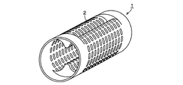
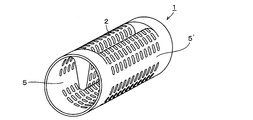
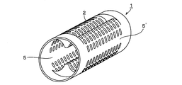
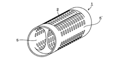
- the entire case wall surface other than the wall surface forming the fluid inflow / outlet boundary portions 5 and 5 ′ provided at the opposite positions in the axial direction of the case wall surface It is a figure which shows the one aspect
- Such a case is used when the outflow and inflow of the fluid is used such that one half of the case wall and the other half, for example, the upper half is for fluid inflow and the lower half is for fluid outflow.
- the fluid outflow / inlet boundary portions 5 and 5 ′ in which the through holes are not formed are provided at the boundary portions of the two portions. Since the fluid outflow inlet / outlet boundary portions 5 and 5 ′ serve as boundaries between the outflow location of the fluid and the inflow location, from the viewpoint of efficiently supplying the fluid to the recess, preferably the opposite position of the case wall that is not the recess formation site, More preferably, it is provided on both side surfaces in the longitudinal direction of the case in a strip shape at opposite positions symmetrical to the recessed portion.
- the total opening portion area of the through holes provided at the outflow location or the inflow location of the fluid is preferably formed to be a ratio of about 50% of the total opening portion area of all the through holes.
- the fluid outflow / inlet boundary portions 5 and 5 ' have an advantage that they can be used as a parting surface of the mold.
- FIG. 7a is a perspective view showing a case in which a partition 7 is further provided in a cylindrical portion at both ends of the case that accommodates the hollow fiber membrane bundle illustrated in FIG. 1, and FIG. 7b is a side view thereof.
- a partition 7 is provided in order to isolate a portion where the hollow fiber membrane bundle is not filled from the inside of the cylinder at both ends of the case from a portion where the hollow fiber membrane bundle is filled, preferably as shown in FIG. 7b. It is comprised so that it may become the same shape as the dent of a case center part.
- FIG. 7c As shown in the centerline longitudinal end view of the hollow fiber membrane module shown in FIG. 7c and the side view of the hollow fiber membrane module shown in FIG. 7d (the hollow fiber membrane bundle is not shown), by providing such a partition 7, Since the space portion 5 that is not filled with the yarn membrane bundle 3 does not need to be filled with the potting material, the amount of the potting material used can be reduced.
- the hollow fiber membrane may melt depending on the amount of heat generated. To avoid this, the amount of potting material to be introduced is limited by one operation. However, as the amount of the potting material increases, the cycle time for manufacturing the hollow fiber membrane module becomes longer. On the other hand, when the partition 7 that can isolate the space that is not filled with the hollow fiber membrane bundle is provided, the amount of the potting material corresponding to the space volume can be reduced. In addition to the reduction in the amount of potting material used during production, the present invention has an excellent effect that the cycle time for producing the hollow fiber membrane module can be suppressed from becoming longer than necessary.
- the case where the potting material contact part has a recessed cylindrical shape increases the surface area of the case where the potting material abuts, that is, the bonding area increases.
- the strength can be increased, and the pressure receiving area of the potting portion is reduced. Therefore, the strength can be increased also in this respect. Therefore, the amount of potting material can be further reduced by shortening the length of the potting part, taking into account the increase in strength, which can also increase the recessed shape part in the center of the case. It becomes.
- FIGS. 8 to 9 are perspective views showing a case in which a partition 7 is further provided on both ends of the cylindrical portion of the case that accommodates the hollow fiber membrane bundle illustrated in FIGS.
- a partition 7 is provided in order to isolate a portion where the hollow fiber membrane bundle is not filled from the inside of the cylinders at both ends of the case from the portion where the hollow fiber membrane bundle is filled, and is preferably shown in FIGS. It is comprised so that it may become the same shape as the dent of a case center part.
- the hollow fiber membrane module case according to the present invention includes, for example, a humidifying hollow fiber membrane module used in a humidifier for humidifying fuel gas supplied to a polymer electrolyte fuel cell, and a dehumidifying hollow fiber membrane. It is effectively used as a case for modules, hollow fiber membrane modules used for fluid filtration, separation, and concentration.
Landscapes
- Chemical & Material Sciences (AREA)
- Chemical Kinetics & Catalysis (AREA)
- Life Sciences & Earth Sciences (AREA)
- Engineering & Computer Science (AREA)
- Manufacturing & Machinery (AREA)
- Sustainable Development (AREA)
- Sustainable Energy (AREA)
- Electrochemistry (AREA)
- General Chemical & Material Sciences (AREA)
- Fuel Cell (AREA)
- Separation Using Semi-Permeable Membranes (AREA)
Description
本発明は、中空糸膜モジュール用ケースに関する。さらに詳しくは、加湿装置などとして有効に用いられる中空糸膜モジュール用ケースに関する。
現在、燃料電池などに用いられる加湿装置として、中空糸膜束をケースに挿嵌し、ケース端部でポッティング部を介して中空糸膜端部を固定せしめた中空糸膜モジュールが用いられている。これは、中空糸膜の内側にドライガス(乾燥空気;加湿対象)を、また中空糸膜の外側にウェットガス(湿潤空気)をそれぞれ通気することによりドライガスが加湿されるというものであり、中空糸膜外部に供給されるウェットガスの圧力損失を低減せしめることによりエネルギー効率の向上を図ることができる。
本出願人は先に、中空糸膜外部に供給されるウェットガスの圧力損失を低減せしめた中空糸膜モジュールとして、特許文献1~2でケース付近に設けられた孔近傍において、ケース壁面と中空糸膜束との間に、全周にわたって隙間が設けられているものを提案している。
しかるに、これらの中空糸膜モジュールはケースの極く一部分に貫通穴(ウェットガス導入孔およびウェットガス排出口)が設けられるにとどまっており、中空糸膜束外周面の大部分はケース壁面によって覆われているため、中空糸膜外部に供給されるウェットガスの圧力損失の低減には課題が残っている。
一方、かかる課題に対しては、例えば特許文献3においてケース壁面の貫通穴総面積を増加させるとともに、収容している単位中空糸膜本数当りのケース壁面に設けられる貫通穴による開口部分(開口面積)を増加させることが有効な手段として考えられることから、中空糸膜モジュール断面を円形から矩形あるいはトラック(楕円)形とすることによって単位中空糸膜本数当りのケース表面積を大きくすることが行われている。
しかしながら、このような中空糸膜モジュールでは、下記の如き問題が生じるようになる。
(1) 耐圧容器としての中空糸膜モジュール用ケースといった観点から考えると、断面が矩形あるいはトラック(楕円)形のものは、円形のものと比較して加圧時の変形量あるいは耐圧性が劣ってしまうこととなり、これらの性能を満足させるためには、機械的強度の高い材料を使用したりあるいは肉厚を厚くしたり、リブを追加するなどの設計的な規制事項が増えてしまうため、結果的にコストの面からみて好ましくない。
(2) 中空糸膜モジュールを装着するハウジングとの関係では、スペースを有効に活用するといった観点から中空糸膜モジュールの断面形状とハウジングの断面形状が同じ(相似形)であることが望まれるが、断面が矩形あるいはトラック(楕円)形の中空糸膜モジュールとこれと相似形のハウジングとの間をシールするためには、一般的に用いられているOリングを使用することができず、専用のシール部品が必要となるため、かかる観点からもコスト高となり、また装着性が低下するなどの問題もある。
(1) 耐圧容器としての中空糸膜モジュール用ケースといった観点から考えると、断面が矩形あるいはトラック(楕円)形のものは、円形のものと比較して加圧時の変形量あるいは耐圧性が劣ってしまうこととなり、これらの性能を満足させるためには、機械的強度の高い材料を使用したりあるいは肉厚を厚くしたり、リブを追加するなどの設計的な規制事項が増えてしまうため、結果的にコストの面からみて好ましくない。
(2) 中空糸膜モジュールを装着するハウジングとの関係では、スペースを有効に活用するといった観点から中空糸膜モジュールの断面形状とハウジングの断面形状が同じ(相似形)であることが望まれるが、断面が矩形あるいはトラック(楕円)形の中空糸膜モジュールとこれと相似形のハウジングとの間をシールするためには、一般的に用いられているOリングを使用することができず、専用のシール部品が必要となるため、かかる観点からもコスト高となり、また装着性が低下するなどの問題もある。
本発明の目的は、従来から用いられてきた中空糸膜モジュール用ケースと比べて、加圧時における変形量の増加あるいは耐圧性の低減やケース材料の変更を伴うことなく、中空糸膜モジュールに用いられた場合に、中空糸膜外部に供給される気体または液体の圧力損失を著しく低減せしめることを可能とする中空糸膜モジュール用ケースを提供することにある。
かかる本発明の目的は、中空糸膜束を収容するケース両端部のケースとハウジングとのシール部分における断面形状が円形であり、かつ中空糸膜束端部をケースに固定せしめるポッティング部に当接する壁面を除くケース部分の全部または一部の断面形状が、少なくとも円形断面の一部が凹んだ形状であり、例えばU字形状、H字形状または8の字形状であり、ポッティング部に当接する壁面を除くケース壁面全体または断面形状が少なくとも円形断面の一部が凹んだ形状のケース部分の壁面全体に貫通穴が形成されている中空糸膜モジュール用ケースよって達成される。
本発明に係る中空糸膜モジュール用ケースは、ケース内に収容される中空糸膜本数を大幅に減らすことなく貫通穴を形成する部位におけるケース表面積を増加させたうえでケース壁面に貫通穴を形成せしめているので、ケース壁面の貫通穴による開口部分を増加させることが可能となり、これを用いた中空糸膜モジュールは、従来の中空糸膜モジュールと比較して中空糸膜外に供給される気体または液体の圧力損失を著しく低減することができるといったすぐれた効果を奏する。また、ケース壁面の貫通穴による開口部分を増加させることにより、中空糸膜に空気が流れる際の線速を小さくすることができるので、中空糸膜へ加わる負荷を減らすこととなり、ひいては中空糸膜モジュールの耐久性の向上を達成することができる。
さらに、中空糸膜束を収容するケース両端部のハウジングとのシール部分における断面形状を円形としていることから、矩形あるいはトラック(楕円)形のケースを用いた中空糸膜モジュールに比べて、中空糸膜モジュールケースの加圧時における変形量が抑えられ、また耐圧性もアップさせることができる。
このほか、一部に凹みが設けられていない円形断面の中空糸膜モジュールと比較すると、中空糸膜外部から供給される気体または液体が中空糸膜モジュール中央部近くまで到達しやすい構造となっているので、中空糸膜の配置位置にかかわらず中空糸膜を有効に利用することができ、中空糸膜モジュールの性能をさらに向上させることができる。
本発明に係る中空糸膜モジュール用ケースは、中空糸膜束を収容するケース両端部のケースとハウジングとのシール部分における断面形状が円形であり、かつ中空糸膜束端部をケースに固定せしめるポッティング部に当接する壁面を除くケース部分の全部または一部の断面形状が、少なくとも円形の一部が凹んだ形状、例えばU字形状、H字形状あるいは8の字形状であり、ポッティング部に当接する壁面を除くケース壁面全体または断面形状が少なくとも円形の一部が凹んだ形状のケース部分の壁面全体に貫通穴が形成されており、好ましくはケース断面形状が円形のケース部分において、中空糸膜束が配置されている部分とそれ以外の空間を隔離するように仕切りが設けられている。なお、ポッティング部に当接する壁面を除くケース部分の“一部”断面形状が少なくとも円形断面の一部が凹んだ形状とは、ポッティング部に隣接する部分に円筒形状のケース部位が存在する態様を示している。
以下、図面を参照しながら本発明に係る中空糸膜モジュール用ケースの具体的態様を詳細に説明する。なお、以下に述べる具体的態様はあくまで本発明の一態様を例示しているに過ぎず、本発明は次の各態様に限定されるものではない。
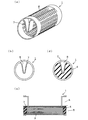
図1には、中空糸膜束を収容するケース1としてU字形状の凹部を有するケースの一態様が示されている。図1aは、U字形状凹部を設けたケースの斜視図であり、図1bはその平面図である。ケース1の両端部は円筒状になっているのに対して、これらに挟まれているケース1の中央部は円筒を構成する壁面の一部が円筒内部に凹んだ形状となっている。ケース形状としてかかる構成を採用することにより、ケース1の中央部においては円筒状の場合と比べてその外表面積を増加せしめることが可能となる。かかる形状のケース1はケース全体を一体的に射出成形しうる形状となっている点にも特徴がある。
ケース壁面のうち、円筒内部に凹んだ形状のケース部位には、凹部を含むその壁面に流体の流出、流入箇所となる貫通穴2が壁面全体に設けられている。流体の流出、流入箇所が特に定められていない場合には、貫通穴はこの図に示されるように一般には縦横両方向に等間隔で設けられる。かかる貫通穴2が設けられているケース表面積を増加させることによって、ケース壁面の貫通穴による開口部分を増加させることができるので、中空糸膜外に供給される気体または液体の圧力損失を著しく低減することが可能となる。
本発明の一態様として、貫通穴は断面形状が少なくとも円形の一部が凹んだ形状のケース部分の壁面全体に設けられる。断面形状が少なくとも円形の一部が凹んだ形状のケース部分の壁面全体とは、図1では円筒内部にU字形状に凹んだ形状のケース部位のケース壁面を意味している。ここで貫通穴2は、この図に示されているように必ずしも等間隔で設ける必要はなく、一箇所に大きく設けることも可能であるが、ケース強度あるいは各中空糸膜への流体の均一な到達といった観点からは、ケース壁面の一部にのみ貫通穴を設ける構成よりも、この図示された態様のように一般に縦横両方向に等間隔で複数の貫通穴を設ける構成とすることが好ましい。
図1cは、中空糸膜束を収容した場合に、中空糸膜端部をケース端部に固定するポッティング部に当接することとなるケース部分をケースの長軸方向に対して垂直なA-A’線断面で示した図であり、円筒部分の奥にケース壁面の一部が円筒内部に凹んだ形状が示されている。
図1dは、ケース中央部分をケースの長軸方向に対して垂直なB-B’線端面で示した図であり、ケース壁面の一部が円筒内部に凹んだ形状は円筒形状の壁面よりもケース表面積が大幅に増加していることが示されている。
本発明の中空糸膜モジュール用ケースでは、ハウジングとのシール部分は、図1cに示される如く、断面形状が円形となる部分に設けられる。このことにより、中空糸膜モジュールケースの耐圧性を担保し、加圧時の変形量を抑えることができる。その一方で、ケース中央部の断面形状をU字形状とすることにより、中空糸膜本数を大幅に減らすことなく、貫通穴を形成するケース表面積を増加せしめている。
図1eは、図1aのケース内に充填される複数の中空糸膜からなる中空糸膜束3を収容し、中空糸膜束端部を中空糸膜の中空内部のみが外部に開放されるように各中空糸膜の外壁面間およびケース1の内壁面間を封止固定するポッティング部4を備えている中空糸膜モジュール6の長さ方向中心線縦端面図を示している。この図1eに示される通り、ケース1の円筒内部に凹んだ部分を除き、ケース1の残りの全内部に中空糸膜が充填され、ケース1の円筒形状の部位にポッティング部4が形成されている。ここで、ポッティング部4は、円筒形状のケース部位の両端部分に部分的に形成されているが、ポッティング部は円筒形状のケース部位全部に形成することもできる。用いられるポッティング材としては、従来から用いられている公知のもの、例えばエポキシ樹脂、ポリウレタン樹脂などがそのまま用いられる。
ケース1中央部の断面形状をU字とすることにより、中空糸膜外部から供給される気体または液体が中空糸膜モジュール中央部近くまで到達しやすい構造となっているので、中空糸膜の配置位置にかかわらず収容されたすべての中空糸膜を有効に利用することができ、中空糸膜モジュールの性能を向上させることができる。ここで、ケースとしてその中央部が円筒内部に凹んだ形状を有するものを用いることにより、ケース1両端部の円筒形状部分内において、ケース1中央部における凹んだ部分に相当する空間に中空糸膜束3が収容されないこととなるが、その空間についてもポッティング材が充填され、かかる部分もポッティング部4の一部をなして中空糸膜束3のケースへの封止固定が行われる。
なお、特許文献4には、モジュールケースがU字形状となっているものが開示されているが、かかる中空糸膜モジュールは、凹部となっていないケース表面のごく一部および凹んだ部分の頂点にそれぞれ開口部が形成されており、一方の開口部から流入したガスが中空糸膜内外を経て他方の開口部へ流れる構造となっている。これに対して本発明はケース壁面の全体的に貫通穴を設けることで開口部分を増加させてガス等の流出入口を増加せしめ、ひいては中空糸膜外に供給される気体または液体の圧力損失を著しく低減することができるといったすぐれた効果を奏するものであり、特許文献4記載の発明とはその構成および効果を全く異にしているといえる。
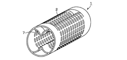
図2は、中空糸膜束を収容するケース1としてH字形状の凹部(相対する2箇所のU字形状凹部)を有するケースの一態様を示した斜視図である。ケース1の両端部はハウジングとのシール部分も含めて円筒状になっているのに対して、これらに挟まれているケース中央部は円筒を構成する壁面の相対する二箇所が円筒内部にU字形状に凹んだ形状となっており、その長軸方向に対して垂直方向の横断面はケース枠形状がH字形状となる。ケース形状としてかかる構成を採用することにより、図1の場合と同様にケース1中央部においては円筒状の場合と比べてその外表面積を増加せしめることが可能となる。
かかるケース形状についてもケース1全体を一体的に射出成形しうる形状となっている点にも特徴がある。そしてケース壁面のうち、円筒内部に凹んだ形状のケース部位には図1のケースと同様にその壁面に流体の流出、流入箇所となる貫通穴2が縦横両方向に等間隔で設けられており、かかる貫通穴2が設けられているケース表面積を増加させることによって、ケース壁面の貫通穴による開口部分を増加させることができるので、中空糸膜外に供給される気体または液体の圧力損失を著しく低減することが可能となる。
図3は、中空糸膜束を収容するケース1として8の字形状のケースの一態様を示した斜視図である。ケース1の両端部はハウジングとのシール部分も含めて円筒状になっているのに対して、これらに挟まれているケース中央部は円筒を構成する壁面の相対する二箇所が円筒内部方向に凹み、凹んだ部分の頂点が肉厚を有して連結した形状となっており、その長軸方向に対して垂直方向の横断面はケース枠形状が8の字形状となる。ケース形状としてかかる構成を採用することにより、図1~2の場合と同様にケース1中央部においては円筒状の場合と比べてその外表面積を増加せしめることが可能となる。
かかるケース形状についてもケース1全体を一体的に射出成形しうる形状となっている点にも特徴がある。そしてケース壁面のうち、円筒内部に凹んだ形状のケース部位には図1のケースと同様にその壁面に流体の流出、流入箇所となる貫通穴2が縦横両方向に等間隔で設けられており、かかる貫通穴2が設けられているケース表面積を増加させることによって、ケース壁面の貫通穴による開口部分を増加させることができるので、中空糸膜外に供給される気体または液体の圧力損失を著しく低減することが可能となる。
図4~6は、図1~3のケース1のように断面形状が少なくとも円形断面の一部が凹んだ形状のケース部分の壁面全体に貫通穴2が形成されているのではなく、断面形状が少なくとも円形の一部が凹んだ形状のケース部分の壁面に加えて、ケース壁面の軸方向の相対する位置に設けられた流体流出入口境界部5,5’をなす壁面以外のケース壁面全体に貫通穴2が形成されている中空糸膜モジュール用ケースの一態様を示す図である。かかるケースは流体の流出、流入箇所がケース壁面の片半分と他の片半分、例えば上半分を流体流入用と下半分を流体流出用というように使用される場合に用いられるものであり、これらの箇所の境界部分に貫通穴が形成されない流体流出入口境界部5,5’が設けられる。流体流出入口境界部5,5’は、流体の流出箇所、流入箇所の境界となるので、凹部に効率よく流体を供給するといった観点から、好ましくは凹部形成部位ではないケース壁面の相対する位置、さらに好ましくはケースの長さ方向両側面に、凹んだ部分に対して対称的な相対する位置に帯状に設けられる。また、流体の流出箇所または流入箇所に設けられる貫通穴総開口部分面積は、好ましくはそれぞれ全貫通穴の総開口部分面積の50%前後の割合となるように形成される。この流体流出入口境界部5,5’は成形型の型割面として使用することもできるといった利点を有する。
図7aは、図1で例示した中空糸膜束を収容するケース両端部の円筒部分に、さらに仕切り7を設けたケースを示した斜視図であり、図7bはその側面図である。かかる仕切り7は、ケース両端部の円筒内部のうち、中空糸膜束が充填されない箇所を中空糸膜束が充填される箇所と隔離するために設けられており、好ましくは図7bに示されるようにケース中央部の凹みと同形状となるように構成される。図7cに示された中空糸膜モジュールの中心線縦端面図および図7d中空糸膜モジュールの側面図(中空糸膜束は図示せず)に示される通り、かかる仕切り7を設けることにより、中空糸膜束3が充填されない空間部5には、ポッティング材を充填する必要がなくなるため、ポッティング材の使用量を低減せしめることが可能となる。
ポッティング材は、硬化する際にその中央部が発熱するため発熱量によっては中空糸膜が溶けてしまう場合があり、これを避けるためには一操作により投入するポッティング材量を制限することとなるが、このことによりポッティング材量が増えれば増えるほど、中空糸膜モジュール製造のサイクルタイムが長くなってしまうこととなる。これに対して、中空糸膜束が充填されない空間について隔離することを可能とする仕切り7を設けた場合には、かかる空間体積分のポッティング材量を減少させることができるので、中空糸膜モジュール製造時におけるポッティング材使用量の減少に加えて、中空糸膜モジュール製造のサイクルタイムが必要以上に長くなることを抑制し得るといったすぐれた効果を奏する。
また、ポッティング材接触部分のケース形状が円筒ものに比べて、円筒の一部が凹んでいるものの方が、ポッティング材が当接するケース等の表面積が増加し、すなわち接着面積が増えることとなり、接着強度の増加を図ることができるとともに、ポッティング部の受圧面積が減少するので、この点においても強度増加が図られることとなる。従って、逆にかかる強度増加分を加味して、ポッティング部の長さを短くすることでさらにポッティング材量を減少させることもでき、これによってケース中央部の凹んだ形状部分を増加せしめることも可能となる。
図8~9は、図2~3で例示した中空糸膜束を収容するケースの両端円筒部分に、さらに仕切り7を設けたケースを示した斜視図である。かかる仕切り7は、ケース両端部の円筒内部のうち、中空糸膜束が充填されない箇所を中空糸膜束が充填される箇所と隔離するために設けられており、好ましくは図8~9に示されるようにケース中央部の凹みと同形状となるように構成される。
本発明に係る中空糸膜モジュール用ケースは、例えば固体高分子型燃料電池に供給する燃料ガスを加湿するための加湿器等に使用される加湿用中空糸膜モジュールのほか、除湿用中空糸膜モジュール、流体のろ過、分離、濃縮に用いられる中空糸膜モジュールなどのケースとして有効に用いられる。
1 ケース
2 貫通穴
3 中空糸膜束
4 ポッティング部
5,5’ 流体流出入口境界部
6 中空糸膜モジュール
7 仕切り
8 空間部(ポッティング剤なし)
2 貫通穴
3 中空糸膜束
4 ポッティング部
5,5’ 流体流出入口境界部
6 中空糸膜モジュール
7 仕切り
8 空間部(ポッティング剤なし)
Claims (11)
- 中空糸膜束を収容するケース両端部のケースとハウジングとのシール部分における断面形状が円形であり、かつ中空糸膜束端部をケースに固定せしめるポッティング部に当接する壁面を除くケース部分の全部または一部の断面形状が、少なくとも円形断面の一部が凹んだ形状であり、ポッティング部に当接する壁面を除くケース壁面全体またはポッティング部に当接するケース壁面およびケース壁面の相対する位置に設けられた流体流出入口境界部をなす壁面以外のケース壁面全体に貫通穴が形成されている中空糸膜モジュール用ケース。
- 中空糸膜束を収容するケース両端部のケースとハウジングとのシール部分における断面形状が円形であり、かつ中空糸膜束端部をケースに固定せしめるポッティング部に当接する壁面を除くケース部分の全部または一部の断面形状が、少なくとも円形断面の一部が凹んだ形状であり、その断面形状が少なくとも円形の一部が凹んだ形状のケース部分の壁面全体またはその断面形状が少なくとも円形の一部が凹んだ形状のケース部分の壁面およびケース壁面の相対する位置に設けられた流体流出入口境界部をなす壁面以外のケース壁面全体に貫通穴が形成されている中空糸膜モジュール用ケース。
- ケース全体が一体的に射出成形可能な形状である請求項1または2記載の中空糸膜モジュール用ケース。
- 円形断面の一部が凹んだ形状が、U字形状、H字形状または8の字形状である請求項1または2記載の中空糸膜モジュール用ケース。
- 貫通穴が、等間隔で形成されている請求項1または2記載の中空糸膜モジュール用ケース。
- 流体流出入口境界部が、ケースの長さ方向側面に、相対する位置に帯状に設けられている請求項1または2記載の中空糸膜モジュール用ケース。
- 流体流出入口境界部が、ケースの長さ方向側面に、凹んだ部分に対して対称的な相対する位置に帯状に設けられている請求項1または2記載の中空糸膜モジュール用ケース。
- ケース両端部の円筒部分に、中空糸膜束が充填されない箇所を中空糸膜束が充填される箇所と隔離するための仕切りがさらに設けられた請求項1または2記載の中空糸膜モジュール用ケース。
- 請求項1または2のいずれかに記載の中空糸膜モジュールケースに複数の中空糸膜からなる中空糸膜束を収容し、中空糸膜束端部を中空糸膜の中空内部のみが外部に開放されるように各中空糸膜の外壁面間およびケースの内壁面間を封止固定したポッティング部を備えた中空糸膜モジュール。
- 加湿装置として用いられる請求項9記載の中空糸膜モジュール。
- 加湿装置が、燃料電池の加湿装置である請求項10記載の中空糸膜モジュール。
Applications Claiming Priority (2)
| Application Number | Priority Date | Filing Date | Title |
|---|---|---|---|
| JP2012222977A JP2015226859A (ja) | 2012-10-05 | 2012-10-05 | 中空糸膜モジュール用ケース |
| JP2012-222977 | 2012-10-05 |
Publications (1)
| Publication Number | Publication Date |
|---|---|
| WO2014054740A1 true WO2014054740A1 (ja) | 2014-04-10 |
Family
ID=50435059
Family Applications (1)
| Application Number | Title | Priority Date | Filing Date |
|---|---|---|---|
| PCT/JP2013/076956 Ceased WO2014054740A1 (ja) | 2012-10-05 | 2013-10-03 | 中空糸膜モジュール用ケース |
Country Status (2)
| Country | Link |
|---|---|
| JP (1) | JP2015226859A (ja) |
| WO (1) | WO2014054740A1 (ja) |
Cited By (2)
| Publication number | Priority date | Publication date | Assignee | Title |
|---|---|---|---|---|
| WO2017105356A1 (en) * | 2015-12-18 | 2017-06-22 | Ak-Kim Kimya Sanayi Ve Ticaret Anonim Sirketi | Hollow fiber membrane module |
| EP4349466A4 (en) * | 2021-06-02 | 2025-04-30 | NOK Corporation | HOLLOW FIBER MEMBRANE MODULE |
Families Citing this family (5)
| Publication number | Priority date | Publication date | Assignee | Title |
|---|---|---|---|---|
| DE112018001968T5 (de) | 2017-04-11 | 2019-12-19 | Nok Corporation | Hohlfasermembranmodul |
| EP4300641A4 (en) * | 2021-05-17 | 2024-12-11 | Kolon Industries, Inc. | CARTRIDGE FOR FUEL CELL HUMIDIFIER AND FUEL CELL HUMIDIFIER |
| KR102824037B1 (ko) * | 2021-05-17 | 2025-06-20 | 코오롱인더스트리 주식회사 | 연료전지용 가습기의 카트리지 및 연료전지용 가습기 |
| KR102926188B1 (ko) * | 2021-09-06 | 2026-02-10 | 코오롱인더스트리 주식회사 | 막가습기용 카트리지 및 이를 포함하는 연료전지 막가습기 |
| KR20250014265A (ko) * | 2023-07-19 | 2025-02-03 | 코오롱인더스트리 주식회사 | 막가습기용 카트리지 및 이를 구비한 막가습기 |
Citations (7)
| Publication number | Priority date | Publication date | Assignee | Title |
|---|---|---|---|---|
| JP2003038938A (ja) * | 2001-07-31 | 2003-02-12 | Nok Corp | 中空糸膜モジュール |
| JP2005155994A (ja) * | 2003-11-25 | 2005-06-16 | Nissan Motor Co Ltd | 中空糸膜加湿器 |
| JP2006142176A (ja) * | 2004-11-18 | 2006-06-08 | Nok Corp | 分離装置及びシール |
| JP2008307432A (ja) * | 2007-06-12 | 2008-12-25 | Honda Motor Co Ltd | 加湿装置 |
| JP2010071619A (ja) * | 2008-09-22 | 2010-04-02 | Nissan Motor Co Ltd | 加湿装置 |
| JP2010107098A (ja) * | 2008-10-30 | 2010-05-13 | Honda Motor Co Ltd | 加湿器 |
| JP2010127582A (ja) * | 2008-11-28 | 2010-06-10 | Nissan Motor Co Ltd | 加湿装置 |
-
2012
- 2012-10-05 JP JP2012222977A patent/JP2015226859A/ja active Pending
-
2013
- 2013-10-03 WO PCT/JP2013/076956 patent/WO2014054740A1/ja not_active Ceased
Patent Citations (7)
| Publication number | Priority date | Publication date | Assignee | Title |
|---|---|---|---|---|
| JP2003038938A (ja) * | 2001-07-31 | 2003-02-12 | Nok Corp | 中空糸膜モジュール |
| JP2005155994A (ja) * | 2003-11-25 | 2005-06-16 | Nissan Motor Co Ltd | 中空糸膜加湿器 |
| JP2006142176A (ja) * | 2004-11-18 | 2006-06-08 | Nok Corp | 分離装置及びシール |
| JP2008307432A (ja) * | 2007-06-12 | 2008-12-25 | Honda Motor Co Ltd | 加湿装置 |
| JP2010071619A (ja) * | 2008-09-22 | 2010-04-02 | Nissan Motor Co Ltd | 加湿装置 |
| JP2010107098A (ja) * | 2008-10-30 | 2010-05-13 | Honda Motor Co Ltd | 加湿器 |
| JP2010127582A (ja) * | 2008-11-28 | 2010-06-10 | Nissan Motor Co Ltd | 加湿装置 |
Cited By (2)
| Publication number | Priority date | Publication date | Assignee | Title |
|---|---|---|---|---|
| WO2017105356A1 (en) * | 2015-12-18 | 2017-06-22 | Ak-Kim Kimya Sanayi Ve Ticaret Anonim Sirketi | Hollow fiber membrane module |
| EP4349466A4 (en) * | 2021-06-02 | 2025-04-30 | NOK Corporation | HOLLOW FIBER MEMBRANE MODULE |
Also Published As
| Publication number | Publication date |
|---|---|
| JP2015226859A (ja) | 2015-12-17 |
Similar Documents
| Publication | Publication Date | Title |
|---|---|---|
| WO2014054740A1 (ja) | 中空糸膜モジュール用ケース | |
| CN101959582B (zh) | 加湿膜组件 | |
| CN107771365B (zh) | 中空纤维膜组件 | |
| KR20090071556A (ko) | 중공사막 모듈 | |
| JP5012109B2 (ja) | 中空糸膜モジュール | |
| US20240145741A1 (en) | Humidifying device having channel plates and channel plate for humidifying device | |
| JP7607122B2 (ja) | 中空糸膜モジュール | |
| CA2604792C (en) | Hollow fiber membrane module, and method for producing the hollow fiber membrane module | |
| JP2004209418A (ja) | 中空糸膜モジュール | |
| CN111683730B (zh) | 中空纤维膜组件 | |
| KR20130031340A (ko) | 나선형 분리막 엘리먼트, 구멍이 있는 중공관 및 그의 제조 방법 | |
| CN106334456A (zh) | 一种中空纤维分离膜组件 | |
| CN104205450B (zh) | 燃料电池 | |
| JP2007216176A (ja) | 中空糸膜モジュール | |
| WO2014069162A1 (ja) | 中空糸膜モジュール用ケース | |
| JP2010127582A (ja) | 加湿装置 | |
| EP4561738A2 (en) | Stack of plates for a humidifier and humidifier | |
| KR102882722B1 (ko) | 연료전지용 막가습기 | |
| JP2006314890A (ja) | 中空糸膜モジュール | |
| CN201096077Y (zh) | 气动化工泵 | |
| JP2007059330A (ja) | 固体高分子形燃料電池 | |
| IT202000025762A1 (it) | Ossigenatore di fluidi organici | |
| JP7847918B2 (ja) | 固体高分子形燃料電池 | |
| CN223323839U (zh) | 一种小型血液氧合器 | |
| JP2025144722A (ja) | 中空糸膜モジュール |
Legal Events
| Date | Code | Title | Description |
|---|---|---|---|
| 121 | Ep: the epo has been informed by wipo that ep was designated in this application |
Ref document number: 13843891 Country of ref document: EP Kind code of ref document: A1 |
|
| NENP | Non-entry into the national phase |
Ref country code: DE |
|
| 122 | Ep: pct application non-entry in european phase |
Ref document number: 13843891 Country of ref document: EP Kind code of ref document: A1 |
|
| NENP | Non-entry into the national phase |
Ref country code: JP |