WO2014054654A1 - Switch device - Google Patents
Switch device Download PDFInfo
- Publication number
- WO2014054654A1 WO2014054654A1 PCT/JP2013/076734 JP2013076734W WO2014054654A1 WO 2014054654 A1 WO2014054654 A1 WO 2014054654A1 JP 2013076734 W JP2013076734 W JP 2013076734W WO 2014054654 A1 WO2014054654 A1 WO 2014054654A1
- Authority
- WO
- WIPO (PCT)
- Prior art keywords
- contact
- state
- switch device
- control button
- fixed contact
- Prior art date
Links
Images


Classifications
-
- H—ELECTRICITY
- H01—ELECTRIC ELEMENTS
- H01H—ELECTRIC SWITCHES; RELAYS; SELECTORS; EMERGENCY PROTECTIVE DEVICES
- H01H3/00—Mechanisms for operating contacts
- H01H3/54—Mechanisms for coupling or uncoupling operating parts, driving mechanisms, or contacts
- H01H3/58—Mechanisms for coupling or uncoupling operating parts, driving mechanisms, or contacts using friction, toothed, or other mechanical clutch
-
- H—ELECTRICITY
- H01—ELECTRIC ELEMENTS
- H01H—ELECTRIC SWITCHES; RELAYS; SELECTORS; EMERGENCY PROTECTIVE DEVICES
- H01H23/00—Tumbler or rocker switches, i.e. switches characterised by being operated by rocking an operating member in the form of a rocker button
- H01H23/02—Details
- H01H23/12—Movable parts; Contacts mounted thereon
- H01H23/16—Driving mechanisms
- H01H23/20—Driving mechanisms having snap action
-
- H—ELECTRICITY
- H01—ELECTRIC ELEMENTS
- H01H—ELECTRIC SWITCHES; RELAYS; SELECTORS; EMERGENCY PROTECTIVE DEVICES
- H01H23/00—Tumbler or rocker switches, i.e. switches characterised by being operated by rocking an operating member in the form of a rocker button
- H01H23/02—Details
-
- H—ELECTRICITY
- H01—ELECTRIC ELEMENTS
- H01H—ELECTRIC SWITCHES; RELAYS; SELECTORS; EMERGENCY PROTECTIVE DEVICES
- H01H23/00—Tumbler or rocker switches, i.e. switches characterised by being operated by rocking an operating member in the form of a rocker button
- H01H23/02—Details
- H01H23/04—Cases; Covers
-
- H—ELECTRICITY
- H01—ELECTRIC ELEMENTS
- H01H—ELECTRIC SWITCHES; RELAYS; SELECTORS; EMERGENCY PROTECTIVE DEVICES
- H01H23/00—Tumbler or rocker switches, i.e. switches characterised by being operated by rocking an operating member in the form of a rocker button
- H01H23/24—Tumbler or rocker switches, i.e. switches characterised by being operated by rocking an operating member in the form of a rocker button with two operating positions
-
- H—ELECTRICITY
- H01—ELECTRIC ELEMENTS
- H01H—ELECTRIC SWITCHES; RELAYS; SELECTORS; EMERGENCY PROTECTIVE DEVICES
- H01H2221/00—Actuators
- H01H2221/008—Actuators other then push button
- H01H2221/016—Lever; Rocker
-
- H—ELECTRICITY
- H01—ELECTRIC ELEMENTS
- H01H—ELECTRIC SWITCHES; RELAYS; SELECTORS; EMERGENCY PROTECTIVE DEVICES
- H01H2221/00—Actuators
- H01H2221/036—Return force
- H01H2221/044—Elastic part on actuator or casing
-
- H—ELECTRICITY
- H01—ELECTRIC ELEMENTS
- H01H—ELECTRIC SWITCHES; RELAYS; SELECTORS; EMERGENCY PROTECTIVE DEVICES
- H01H2239/00—Miscellaneous
- H01H2239/03—Avoiding erroneous switching
-
- H—ELECTRICITY
- H01—ELECTRIC ELEMENTS
- H01H—ELECTRIC SWITCHES; RELAYS; SELECTORS; EMERGENCY PROTECTIVE DEVICES
- H01H2239/00—Miscellaneous
- H01H2239/044—High voltage application
-
- H—ELECTRICITY
- H01—ELECTRIC ELEMENTS
- H01H—ELECTRIC SWITCHES; RELAYS; SELECTORS; EMERGENCY PROTECTIVE DEVICES
- H01H23/00—Tumbler or rocker switches, i.e. switches characterised by being operated by rocking an operating member in the form of a rocker button
- H01H23/02—Details
- H01H23/12—Movable parts; Contacts mounted thereon
- H01H23/16—Driving mechanisms
- H01H23/164—Driving mechanisms with rectilinearly movable member carrying the contacts
-
- H—ELECTRICITY
- H01—ELECTRIC ELEMENTS
- H01H—ELECTRIC SWITCHES; RELAYS; SELECTORS; EMERGENCY PROTECTIVE DEVICES
- H01H23/00—Tumbler or rocker switches, i.e. switches characterised by being operated by rocking an operating member in the form of a rocker button
- H01H23/02—Details
- H01H23/12—Movable parts; Contacts mounted thereon
- H01H23/16—Driving mechanisms
- H01H23/168—Driving mechanisms using cams
-
- H—ELECTRICITY
- H01—ELECTRIC ELEMENTS
- H01H—ELECTRIC SWITCHES; RELAYS; SELECTORS; EMERGENCY PROTECTIVE DEVICES
- H01H5/00—Snap-action arrangements, i.e. in which during a single opening operation or a single closing operation energy is first stored and then released to produce or assist the contact movement
- H01H5/04—Energy stored by deformation of elastic members
- H01H5/045—Energy stored by deformation of elastic members making use of cooperating spring loaded wedging or camming parts between operating member and contact structure
-
- H—ELECTRICITY
- H01—ELECTRIC ELEMENTS
- H01H—ELECTRIC SWITCHES; RELAYS; SELECTORS; EMERGENCY PROTECTIVE DEVICES
- H01H9/00—Details of switching devices, not covered by groups H01H1/00 - H01H7/00
- H01H9/30—Means for extinguishing or preventing arc between current-carrying parts
- H01H9/44—Means for extinguishing or preventing arc between current-carrying parts using blow-out magnet
- H01H9/443—Means for extinguishing or preventing arc between current-carrying parts using blow-out magnet using permanent magnets
Abstract
A switch device comprising: a fixed contact part including a fixed contact point; a moving contact part including a moving contact point; a control button; an operation part including a first end and a second end; and a lock part. Pushing the first end down causes the control button to be pushed by the operation part, bringing the moving contact point into contact with the fixed contact point and turning the device on. When the moving contact point and the fixed contact point are in contact, the first protrusion of the lock part comes in contact with the catch of the control button, restraining the movement of the control button and keeping the device turned on. Pushing the second end down causes the operation part to come in contact with the second protrusion of the lock part, moving the lock part so that the first protrusion separates from the catch and turning the device off.
Description
本発明は、スイッチ装置に関する。
The present invention relates to a switch device.
電源等のオンオフを制御するスイッチとして波形スイッチがある。波形スイッチは、押下部分となる表面が波形に形成されており、波形に形成された表面の押下部分の一方の端部または他方の端部を押下することにより、オンオフの制御を行なうことができるものである。
There is a waveform switch as a switch that controls on / off of the power supply. In the waveform switch, the surface to be a pressed portion is formed in a waveform, and on / off control can be performed by pressing one end or the other end of the pressed portion of the surface formed in the waveform. Is.
このような波形スイッチは、操作等しやすいことの理由から電源等のスイッチに用いられている場合が多い。
Such a waveform switch is often used as a switch for a power supply because it is easy to operate.
ところで、現在、我が国では商用電源は交流の100Vであるが、省エネや高効率化等の観点から、直流の高電圧の電源が求められている。しかしながら、現状におけるスイッチは、交流の100Vに対応しているものであるため、直流、高電圧に用いた場合には、故障や破壊等が発生してしまう。具体的には、直流、高電圧に用いた場合には、オンオフ時、特に、オフ時においてアークが発生しやすくなり、発生したアークの熱により、スイッチ自体が破壊等されてしまう場合がある。このような熱によるスイッチの破壊としては、破壊されてオープン状態になるものとショート状態になるものとがある。特に、ショート状態になる場合には、電流が流れ続け、切断することができなくなってしまうため、スイッチ以外の部分にも影響を与える場合があり、更に問題となる可能性がある。
By the way, at present, in Japan, commercial power is 100V AC, but from the viewpoint of energy saving and high efficiency, a DC high voltage power source is required. However, since the current switch is compatible with 100 V AC, failure or destruction occurs when used for DC or high voltage. Specifically, when it is used for direct current and high voltage, an arc is likely to be generated at the time of on / off, particularly at the time of off, and the switch itself may be destroyed by the heat of the generated arc. There are two types of destruction of the switch due to heat such as destruction and an open state and a short state. In particular, in a short state, current continues to flow and cannot be cut off, which may affect parts other than the switch, which may cause further problems.
よって、現状の電源スイッチと同様の操作を行なうことのできる波形スイッチにおいて、直流または高電圧に対応したスイッチ装置が求められている。
Therefore, there is a demand for a switch device that can handle direct current or high voltage in a waveform switch that can be operated in the same manner as a current power switch.
本発明の実施の形態の一側面によれば、固定接点を含む固定接点部と、可動接点を含む可動接点部と、引っ掛け部を含み、前記可動接点部の一部を支持する制御ボタン部と、表面に第1の端部と第2の端部を含む操作部と、第1の突起部と第2の突起部を含むロック部とを備えるスイッチ装置が提供される。
According to one aspect of the embodiment of the present invention, a fixed contact part including a fixed contact, a movable contact part including a movable contact, a control button part including a hook part and supporting a part of the movable contact part, There is provided a switch device including an operation unit including a first end and a second end on a surface, and a lock unit including a first projection and a second projection.
このスイッチ装置では、前記第1の端部を押下することにより、前記制御ボタン部が押されて、前記可動接点が前記固定接点に接触してオン状態となり、前記第2の端部を押下することにより前記可動接点が前記固定接点から離れてオフ状態となる。前記可動接点と前記固定接点とが接触している状態では、前記制御ボタン部の前記引っ掛け部に、前記ロック部の前記第1の突起部が接触することによりオン状態が維持される。前記操作部の前記第2の端部を押下することにより、前記操作部が前記ロック部の前記第2の突起部に接触して、前記引っ掛け部から前記第1の突起部が離れるように前記ロック部が移動し、オフ状態となる。
In this switch device, when the first end portion is pressed, the control button portion is pressed, the movable contact comes into contact with the fixed contact, and is turned on, and the second end portion is pressed. As a result, the movable contact is separated from the fixed contact and is turned off. In a state where the movable contact and the fixed contact are in contact with each other, the on state is maintained when the first protrusion of the lock portion contacts the hook portion of the control button portion. By depressing the second end portion of the operation portion, the operation portion comes into contact with the second protrusion portion of the lock portion, and the first protrusion portion is separated from the hook portion. The lock part moves and is turned off.
本発明によれば、波形スイッチにおいて、直流または高電圧に対応したスイッチ装置を提供することができる。
According to the present invention, it is possible to provide a switching device that supports direct current or high voltage in a waveform switch.
本発明を実施するための形態について、以下に説明する。尚、同じ部材等については、同一の符号を付して説明を省略する。
直流、高電圧における電源等に用いられるスイッチに求められている内容を説明する。スイッチの接点間に高い電圧、例えば、高電圧の直流が印加されている場合、スイッチをオン、オフする際には、接点同士が接触していない状態においても、接点間にアークが発生しアーク電流が流れる。このようにアークが発生すると、発生したアークにより接点等が高温となるため、スイッチが故障し、破壊される場合がある。このため、アークを発生させない構造のスイッチ、または、アークが発生してもできるだけ短時間でアークを消弧させることができるスイッチが求められる。 The form for implementing this invention is demonstrated below. In addition, about the same member etc., the same code | symbol is attached | subjected and description is abbreviate | omitted.
The contents required for a switch used for a power source or the like at DC or high voltage will be described. When a high voltage, for example, a high-voltage direct current, is applied between the contact points of the switch, when the switch is turned on / off, an arc is generated between the contacts even when the contacts are not in contact with each other. Current flows. When an arc is generated in this way, the contact or the like becomes hot due to the generated arc, and the switch may fail and be destroyed. For this reason, a switch having a structure that does not generate an arc, or a switch that can extinguish an arc in as short a time as possible even when the arc occurs is required.
〔第1の実施の形態〕
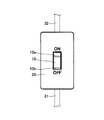
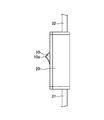
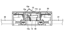
第1の実施の形態におけるスイッチ装置について、図1~図3に基づき説明する。図1は本実施の形態におけるスイッチ装置の斜視図であり、図2は上面図であり、図3は側面図である。本実施の形態におけるスイッチ装置は、波形スイッチであり、表面が波形の形状で形成されている操作部10を有している。本実施の形態におけるスイッチ装置は、全体が筐体部20に覆われており、筐体部20に設けられている開口部から波形の操作部10が出ている。また、本実施の形態におけるスイッチ装置には、2本の電源ケーブル31、32が接続されており、一方の電源ケーブル31からは電力、例えば、直流400Vの電力等が供給されている。 [First Embodiment]
The switch device according to the first embodiment will be described with reference to FIGS. FIG. 1 is a perspective view of a switch device according to the present embodiment, FIG. 2 is a top view, and FIG. 3 is a side view. The switch device in the present embodiment is a waveform switch, and has anoperation unit 10 whose surface is formed in a waveform shape. The switch device according to the present embodiment is entirely covered with the casing unit 20, and the waveform operation unit 10 is projected from an opening provided in the casing unit 20. In addition, two power cables 31 and 32 are connected to the switch device in the present embodiment, and power, for example, DC 400V power or the like is supplied from one power cable 31.
第1の実施の形態におけるスイッチ装置について、図1~図3に基づき説明する。図1は本実施の形態におけるスイッチ装置の斜視図であり、図2は上面図であり、図3は側面図である。本実施の形態におけるスイッチ装置は、波形スイッチであり、表面が波形の形状で形成されている操作部10を有している。本実施の形態におけるスイッチ装置は、全体が筐体部20に覆われており、筐体部20に設けられている開口部から波形の操作部10が出ている。また、本実施の形態におけるスイッチ装置には、2本の電源ケーブル31、32が接続されており、一方の電源ケーブル31からは電力、例えば、直流400Vの電力等が供給されている。 [First Embodiment]
The switch device according to the first embodiment will be described with reference to FIGS. FIG. 1 is a perspective view of a switch device according to the present embodiment, FIG. 2 is a top view, and FIG. 3 is a side view. The switch device in the present embodiment is a waveform switch, and has an
操作部10では、表面の波形の一方の端部10aまたは他方の端部10bを押下することにより、スイッチのオンまたはオフの制御を行なうことができる。具体的には、オフ状態から操作部10の一方の端部10aを指等により押下するとオン状態となり、一方の電源ケーブル31と他方の電源ケーブル32とが電気的に接続され、一方の電源ケーブル31から他方の電源ケーブル32に電力が供給される。この際、操作部10における他方の端部10bは上に上がる。また、オン状態から操作部10の他方の端部10bを指等により押下するとオフ状態となり、一方の電源ケーブル31と他方の電源ケーブル32との電気的な接続が遮断され、一方の電源ケーブル31から他方の電源ケーブル32への電力の供給が停止する。この際、操作部10における一方の端部10aは上に上がる。
In the operation unit 10, the switch can be turned on or off by pressing down one end 10a or the other end 10b of the waveform on the surface. Specifically, when one end 10a of the operation unit 10 is pressed with a finger or the like from the off state, the power unit 31 is turned on, and one power cable 31 and the other power cable 32 are electrically connected, and one power cable is connected. Power is supplied from 31 to the other power cable 32. At this time, the other end portion 10b of the operation unit 10 rises upward. Further, when the other end portion 10b of the operation unit 10 is pressed with a finger or the like from the on state, the off state is established, and the electrical connection between the one power cable 31 and the other power cable 32 is cut off, and the one power cable 31 is disconnected. Supply of power to the other power cable 32 is stopped. At this time, one end 10a of the operation unit 10 rises upward.
このように、波形スイッチでは、操作部10の一方の端部10aを押下すると他方の端部10bが上がり、上がっている状態の他方の端部10aを押下すると一方の端部10aが上がるため、シーソー型スイッチとも呼ばれている。
Thus, in the waveform switch, when one end 10a of the operation unit 10 is pressed down, the other end 10b is raised, and when the other end 10a in the raised state is pressed down, one end 10a is raised, It is also called a seesaw type switch.
(内部構造)
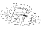
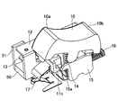
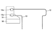
次に、図4から図6に基づき、本実施の形態におけるスイッチ装置の内部構造について説明する。図4は、本実施の形態におけるスイッチ装置から筐体部20を取り除いた状態を示す斜視図であり、図5は、一部を透過した側面図であり、図6は、図4から更に操作部10を取り除いた状態を示す斜視図である。 (Internal structure)
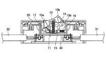
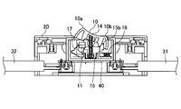
Next, the internal structure of the switch device according to the present embodiment will be described with reference to FIGS. FIG. 4 is a perspective view showing a state in which thecasing unit 20 is removed from the switch device according to the present embodiment, FIG. 5 is a side view partially transmitting, and FIG. 6 is a further operation from FIG. It is a perspective view which shows the state which removed the part 10. FIG.
次に、図4から図6に基づき、本実施の形態におけるスイッチ装置の内部構造について説明する。図4は、本実施の形態におけるスイッチ装置から筐体部20を取り除いた状態を示す斜視図であり、図5は、一部を透過した側面図であり、図6は、図4から更に操作部10を取り除いた状態を示す斜視図である。 (Internal structure)
Next, the internal structure of the switch device according to the present embodiment will be described with reference to FIGS. FIG. 4 is a perspective view showing a state in which the
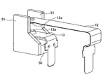
本実施の形態におけるスイッチ装置は、1つの可動接点部12と1つの固定接点部13とが1組のスイッチとなっており、このような組のスイッチが2組設けられている。具体的には、一方の可動接点部12と一方の固定接点部13とが1組のスイッチとなっており、他方の可動接点部12と他方の固定接点部13とがもう1組のスイッチとなっている。可動接点部12の端部には可動接点12aが設けられており、固定接点部13の端部には固定接点13aが設けられている。本実施形態のスイッチでは、可動接点部12及び固定接点部13は可動接点12a及び固定接点13aを除く全体が導電性を有する板状の銅(Cu)等の金属材料により形成されており、可動接点部12はバネ性を有している。また、可動接点12a、固定接点13aは、銀(Ag)等または銀等を含む材料により形成されている。尚、本実施の形態においては、基板40の上に可動接点部12、固定接点部13等を含む部品が所定の位置に配置されている。
In the switch device according to the present embodiment, one movable contact portion 12 and one fixed contact portion 13 constitute one set of switches, and two sets of such switches are provided. Specifically, one movable contact portion 12 and one fixed contact portion 13 constitute a set of switches, and the other movable contact portion 12 and the other fixed contact portion 13 constitute another set of switches. It has become. A movable contact 12 a is provided at the end of the movable contact portion 12, and a fixed contact 13 a is provided at the end of the fixed contact portion 13. In the switch of this embodiment, the movable contact portion 12 and the fixed contact portion 13 are formed of a metal material such as plate-like copper (Cu) having conductivity, except for the movable contact 12a and the fixed contact 13a. The contact portion 12 has a spring property. The movable contact 12a and the fixed contact 13a are made of silver (Ag) or the like or a material containing silver or the like. In the present embodiment, components including the movable contact portion 12, the fixed contact portion 13 and the like are disposed on the substrate 40 at predetermined positions.
本実施の形態におけるスイッチ装置では、可動接点部12の可動端子12aが固定接点部13の固定接点13aに接触することによりオン状態となり、離れることによりオフ状態となる。
In the switch device according to the present embodiment, the movable terminal 12a of the movable contact portion 12 is turned on when it contacts the fixed contact 13a of the fixed contact portion 13, and is turned off when it is separated.
また、上述のとおり、本実施の形態におけるスイッチ装置には電源ケーブル31及び32が接続されている。電源ケーブル31は、プラス(+)の電線31aと、マイナス(-)の電線31bと、接地電位(GND)の電線31cとを有している。電源ケーブル32は、プラス(+)の電線32aと、マイナス(-)の電線32bと、接地電位(GND)の電線32cとを有している。
As described above, the power cables 31 and 32 are connected to the switch device in the present embodiment. The power cable 31 includes a positive (+) electric wire 31a, a negative (−) electric wire 31b, and an electric wire 31c having a ground potential (GND). The power cable 32 includes a positive (+) electric wire 32a, a negative (−) electric wire 32b, and an electric wire 32c having a ground potential (GND).
電源ケーブル31のプラス(+)の電線31aは2つの可動接点部12のうちの一方に接続されており、マイナス(-)の電線31bは2つの可動接点部12のうちの他方に接続されている。また、電源ケーブル32のプラス(+)の電線32aは2つの固定接点部13のうちの一方に接続されており、マイナス(-)の電線32bは2つの固定接点部13のうちの他方に接続されている。尚、電源ケーブル31の接地電位(GND)の電線31cと電源ケーブル32の接地電位(GND)の電線32cとはスイッチ装置内で接続されている。
The positive (+) electric wire 31 a of the power cable 31 is connected to one of the two movable contact portions 12, and the negative (−) electric wire 31 b is connected to the other of the two movable contact portions 12. Yes. Further, the positive (+) electric wire 32 a of the power cable 32 is connected to one of the two fixed contact portions 13, and the negative (−) electric wire 32 b is connected to the other of the two fixed contact portions 13. Has been. Note that the ground potential (GND) wire 31c of the power cable 31 and the ground potential (GND) wire 32c of the power cable 32 are connected in the switch device.
(オンオフ操作)
次に、本実施の形態におけるスイッチ装置のオンオフ操作について詳細に説明する。 (On / off operation)
Next, an on / off operation of the switch device according to the present embodiment will be described in detail.
次に、本実施の形態におけるスイッチ装置のオンオフ操作について詳細に説明する。 (On / off operation)
Next, an on / off operation of the switch device according to the present embodiment will be described in detail.
最初に、オン状態について説明する。本実施の形態におけるスイッチ装置の操作部10の下には制御ボタン部11が設けられており、操作部10の一方の端部10aを押下することにより、操作部回転軸10cを中心に操作部10が回動し、操作部10により制御ボタン部11が押されて制御ボタン部回転軸11aを中心に制御ボタン部11が回動する。制御ボタン部11の可動端子支持部11bが可動接点部12の一部を支持しており、制御ボタン部11が制御ボタン部回転軸11aを中心に回動することにより、可動端子支持部11bに支持されている可動接点部12が固定接点部13に近づき、図6に示すように可動接点部12の可動接点12aと固定接点部13の固定接点13aとが接触することにより、オン状態となる。オン状態では、2つの可動接点12aと固定接点13aとが接触することにより、電源ケーブル31におけるプラス(+)の電線31aと電源ケーブル32におけるプラス(+)の電線32aとが電気的に接続され、電源ケーブル31におけるマイナス(-)の電線31bと電源ケーブル32におけるマイナス(-)の電線32bとが電気的に接続される。これにより、電源ケーブル31から電源ケーブル32に電力が供給される。
First, the on state will be described. A control button unit 11 is provided below the operation unit 10 of the switch device according to the present embodiment. By pressing down one end 10a of the operation unit 10, the operation unit centering on the operation unit rotating shaft 10c is provided. 10 is rotated, and the control button unit 11 is pushed by the operation unit 10, and the control button unit 11 is rotated about the control button unit rotation shaft 11a. The movable terminal support part 11b of the control button part 11 supports a part of the movable contact part 12, and when the control button part 11 rotates around the control button part rotation shaft 11a, the movable terminal support part 11b The supported movable contact portion 12 approaches the fixed contact portion 13, and the movable contact portion 12a of the movable contact portion 12 and the fixed contact portion 13a of the fixed contact portion 13 come into contact with each other as shown in FIG. . In the ON state, the two movable contacts 12a and the fixed contact 13a come into contact with each other, so that the plus (+) electric wire 31a in the power cable 31 and the plus (+) electric wire 32a in the power cable 32 are electrically connected. The minus (−) electric wire 31b in the power cable 31 and the minus (−) electric wire 32b in the power cable 32 are electrically connected. As a result, power is supplied from the power cable 31 to the power cable 32.
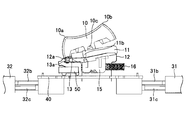
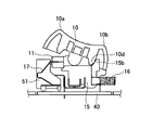
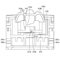
より詳細に、本実施の形態におけるスイッチ装置のオン状態について、図7から図11に基づき説明する。図7は、スイッチ装置がオン状態である場合のスイッチ装置の断面図であり、図8は、オン状態である場合の図7とは異なる部分のスイッチ装置の断面図である。図9は、スイッチ装置がオン状態である場合の内部の様子を示す要部の断面図であり、図10は、オン状態である場合の図9とは異なる部分の要部の断面図であり、図11は斜視図である。
More specifically, the ON state of the switch device according to the present embodiment will be described with reference to FIGS. FIG. 7 is a cross-sectional view of the switch device when the switch device is in the on state, and FIG. 8 is a cross-sectional view of the switch device of a portion different from FIG. 7 when the switch device is in the on state. FIG. 9 is a cross-sectional view of a main part showing an internal state when the switch device is in an on state, and FIG. 10 is a cross-sectional view of a main part of a part different from FIG. 9 in the on state. FIG. 11 is a perspective view.
本実施の形態のスイッチ装置は、オフ状態から操作部10の一方の端部10aを押下することによりオン状態となり、オン状態は操作部バネ14の力により維持される。尚、図7においては便宜上、操作部バネ14はまっすぐに記載されているが、実際は、操作部10の一方の端部10aを押下することにより逆「く」の字状に曲がり、オン状態が維持される。この際、ロック部15がロック部バネ16の復元力により押されて基板40に略平行に図示左方向に移動し、ロック部15の先端部分の第1の突起部15aが制御ボタン部11のL字状の引っ掛け部11cに係合する。この状態においては、図9に示すように、制御ボタン部11は、引っ掛け部11cと係合している第1の突起部15aにより固定されるため、操作部10が操作部回転軸10cを中心に若干回動したとしても、可動接点12aと固定接点13aとの接触状態は保たれ、オン状態は維持される。尚、本実施の形態におけるスイッチ装置では、制御ボタン部11に接続されている復帰バネ17が設けられており、オン状態においては、図10、図11に示すように制御ボタン部11または操作部10により復帰バネ17が押され縮んだ状態となっている。
The switch device according to the present embodiment is turned on by depressing one end 10a of the operation unit 10 from the off state, and the on state is maintained by the force of the operation unit spring 14. In FIG. 7, for convenience, the operation portion spring 14 is straight. However, in actuality, when one end portion 10a of the operation portion 10 is pressed, the operation portion spring 14 is bent into a reverse “<” shape, and the ON state is Maintained. At this time, the lock portion 15 is pushed by the restoring force of the lock portion spring 16 and moves in the left direction in the drawing substantially parallel to the substrate 40, and the first protrusion 15 a at the tip portion of the lock portion 15 is moved to the control button portion 11. Engages with the L-shaped hook 11c. In this state, as shown in FIG. 9, the control button portion 11 is fixed by the first protrusion 15a engaged with the hook portion 11c, so that the operation portion 10 is centered on the operation portion rotation shaft 10c. Even if it is slightly rotated, the contact state between the movable contact 12a and the fixed contact 13a is maintained, and the ON state is maintained. In the switch device according to the present embodiment, a return spring 17 connected to the control button unit 11 is provided, and in the on state, the control button unit 11 or the operation unit as shown in FIGS. 10, the return spring 17 is pushed and contracted.
次に、オン状態からオフ状態に移行する途中の段階について、図12及び図13に基づき説明する。図12は、スイッチ装置がオン状態からオフ状態に移行する途中の段階の内部の様子を示す要部の断面図であり、図13は、この段階における図12とは異なる部分の要部の断面図である。
Next, the stage during the transition from the on state to the off state will be described with reference to FIGS. FIG. 12 is a cross-sectional view of the main part showing an internal state in the middle of the transition of the switch device from the on state to the off state, and FIG. 13 is a cross section of the main part of the part different from FIG. 12 at this stage. FIG.
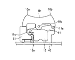
本実施の形態のスイッチ装置は、図10に示すオン状態から操作部10の他方の端部10bを押下すると、操作部回転軸10cを中心に操作部10が回動し、過渡的な状態として図12及び図13に示す状態となる。この状態では、操作部10が制御ボタン部11を押していた力はなくなるものの、図12に示すようにロック部15の第1の突起部15aが制御ボタン部11の引っ掛け部11cに引っかかって制御ボタン部11が固定されている状態にあるため、制御ボタン部11は制御ボタン部回転軸11aを中心に回動することはなく、可動接点12aと固定接点13aとの接触状態が保たれる。よって、オン状態が維持される。
In the switch device according to the present embodiment, when the other end portion 10b of the operation unit 10 is pressed from the on state shown in FIG. 10, the operation unit 10 rotates around the operation unit rotation shaft 10c, which is in a transitional state. The state shown in FIGS. 12 and 13 is obtained. In this state, although the force that the operation unit 10 has pushed the control button unit 11 disappears, the first protrusion 15a of the lock unit 15 is caught by the hook unit 11c of the control button unit 11 as shown in FIG. Since the part 11 is in a fixed state, the control button part 11 does not rotate around the control button part rotation shaft 11a, and the contact state between the movable contact 12a and the fixed contact 13a is maintained. Therefore, the on state is maintained.
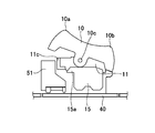
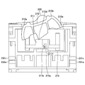
次に、オフ状態について、図14から図18に基づき説明する。図14は、スイッチ装置がオフ状態である場合の断面の断面図であり、図15は、図14とは異なる部分の断面図である。図16は、スイッチ装置がオン状態である場合の内部の様子を示す要部の断面図であり、図17は、図16とは異なる部分の断面図であり、図18は斜視図である。
Next, the off state will be described with reference to FIGS. 14 is a cross-sectional view of a cross section when the switch device is in an OFF state, and FIG. 15 is a cross-sectional view of a portion different from FIG. 16 is a cross-sectional view of a main part showing an internal state when the switch device is in an ON state, FIG. 17 is a cross-sectional view of a portion different from FIG. 16, and FIG. 18 is a perspective view.
本実施の形態におけるスイッチ装置は、図12及び図13に示す状態から更に、操作部10の他方の端部10bを押下することによりオフ状態となる。オフ状態は操作部バネ14の力により維持される。尚、図14においては便宜上、操作部バネ14はまっすぐに記載されているが、実際は、操作部10の他方の端部10bを押下することにより「く」の字状に曲がり、オフ状態が維持される。
The switch device in the present embodiment is turned off by further pressing the other end 10b of the operation unit 10 from the state shown in FIGS. The off state is maintained by the force of the operation portion spring 14. In FIG. 14, for convenience, the operation portion spring 14 is shown straight, but actually, when the other end portion 10b of the operation portion 10 is pressed, the operation portion spring 14 is bent into a "<" shape and the off state is maintained. Is done.
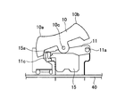
図12及び図13に示す過渡的な状態から、操作部10の他方の端部10bを更に押下することにより、操作部回転軸10cを中心に操作部10が更に回動する。操作部10が回動することにより、図17に示すように操作部10に設けられた凸状のロック解除部10dがロック部15の操作部10側に設けられた第2の突起部15bと接触する。第2の突起部15bには傾斜が設けられており、操作部10におけるロック解除部10dの端がこの傾斜に沿って移動することにより、ロック部15はロック部バネ16の復元力に抗して基板40に平行に図12図示の状態から右方向に移動する。これにより、ロック部15の第1の突起部15aが制御ボタン部11の引っ掛け部11cより離れて制御ボタン部11のロック状態が解除され、復帰バネ17の復元力により制御ボタン部11が押されて制御ボタン部回転軸11aを中心に勢いよく上方向に移動する。制御ボタン部11の上方への移動に応じて、可動端子支持部11bに支持されている可動接点部12が固定接点部13の側から離れるため、図15に示すように可動接点12aと固定接点13aとの接触を解除することができる。本実施の形態におけるスイッチ装置では、復帰バネ17の復元力によりオン状態からオフ状態にできるため、短時間でオフ状態とできる。
12 and 13, when the other end 10 b of the operation unit 10 is further pressed, the operation unit 10 is further rotated around the operation unit rotation shaft 10 c. When the operation unit 10 is rotated, as shown in FIG. 17, the convex unlocking unit 10 d provided on the operation unit 10 is connected to the second protrusion 15 b provided on the operation unit 10 side of the lock unit 15. Contact. The second protrusion 15b is provided with an inclination, and the lock part 15 resists the restoring force of the lock part spring 16 by moving the end of the unlocking part 10d in the operation part 10 along the inclination. Then, it moves in the right direction from the state shown in FIG. As a result, the first protrusion 15 a of the lock portion 15 is separated from the hook portion 11 c of the control button portion 11 and the control button portion 11 is unlocked, and the control button portion 11 is pushed by the restoring force of the return spring 17. As a result, the control button portion is pivoted upward about the rotation shaft 11a. As the control button portion 11 moves upward, the movable contact portion 12 supported by the movable terminal support portion 11b moves away from the fixed contact portion 13 side. Therefore, as shown in FIG. Contact with 13a can be released. In the switch device according to the present embodiment, the on-state can be changed to the off-state by the restoring force of the return spring 17, so that the off-state can be set in a short time.
本実施の形態におけるスイッチ装置では、復帰バネ17の復元力により、極めて短い時間でオン状態からオフ状態にできるため、可動接点12aと固定接点13aとの間にアークが発生しないか、または、発生しても極めて短時間である。従って、可動接点部12が溶けること等によりスイッチ装置が破壊されることはない。
In the switch device according to the present embodiment, the restoring force of the return spring 17 can be turned from the on-state to the off-state in a very short time, so that no arc is generated or generated between the movable contact 12a and the fixed contact 13a. Even in a very short time. Therefore, the switch device is not destroyed by melting the movable contact portion 12 or the like.
(アーク遮断機能)
本実施の形態におけるスイッチ装置には、可動接点12aと固定接点13aとの間で発生したアークを瞬時に遮断する機能が設けられている。図19及び図20等に示すように、本実施の形態におけるスイッチ装置には、固定接点13aの下に永久磁石50が設けられており、永久磁石50により発生した磁界により可動接点12aと固定接点13aとの間で発生したアークを瞬時に消弧させる。アークは電子の流れであることから、磁界が存在していると、磁界により電子に力が加わるため、発生したアークを吹飛ばすように消弧させることができる。本実施の形態においては、可動接点12aと固定接点13aとの間に効率よく磁界が印加されるように、永久磁石50と接する2枚のヨーク51が設けられている。2枚のヨーク51は、永久磁石50、可動接点12a及び固定接点13aの両側に設置されている。これにより、可動接点12aと固定接点13aとの間に磁界を印加することができ、より具体的には、可動接点12aと固定接点13aとを結ぶ線に対して略垂直方向に磁界を印加することができる。尚、図19は永久磁石50及びヨーク51の配置を示す斜視図であり、図20は断面図である。 (Arc break function)
The switch device according to the present embodiment is provided with a function for instantaneously interrupting an arc generated between themovable contact 12a and the fixed contact 13a. As shown in FIGS. 19 and 20, the switch device according to the present embodiment is provided with a permanent magnet 50 below the fixed contact 13 a, and the movable contact 12 a and the fixed contact are generated by the magnetic field generated by the permanent magnet 50. The arc generated between the terminals 13a is extinguished instantaneously. Since the arc is a flow of electrons, if a magnetic field is present, a force is applied to the electrons by the magnetic field, so that the generated arc can be extinguished so as to blow away. In the present embodiment, two yokes 51 in contact with the permanent magnet 50 are provided so that a magnetic field is efficiently applied between the movable contact 12a and the fixed contact 13a. The two yokes 51 are installed on both sides of the permanent magnet 50, the movable contact 12a, and the fixed contact 13a. Thereby, a magnetic field can be applied between the movable contact 12a and the fixed contact 13a, and more specifically, a magnetic field is applied in a direction substantially perpendicular to a line connecting the movable contact 12a and the fixed contact 13a. be able to. 19 is a perspective view showing the arrangement of the permanent magnet 50 and the yoke 51, and FIG. 20 is a cross-sectional view.
本実施の形態におけるスイッチ装置には、可動接点12aと固定接点13aとの間で発生したアークを瞬時に遮断する機能が設けられている。図19及び図20等に示すように、本実施の形態におけるスイッチ装置には、固定接点13aの下に永久磁石50が設けられており、永久磁石50により発生した磁界により可動接点12aと固定接点13aとの間で発生したアークを瞬時に消弧させる。アークは電子の流れであることから、磁界が存在していると、磁界により電子に力が加わるため、発生したアークを吹飛ばすように消弧させることができる。本実施の形態においては、可動接点12aと固定接点13aとの間に効率よく磁界が印加されるように、永久磁石50と接する2枚のヨーク51が設けられている。2枚のヨーク51は、永久磁石50、可動接点12a及び固定接点13aの両側に設置されている。これにより、可動接点12aと固定接点13aとの間に磁界を印加することができ、より具体的には、可動接点12aと固定接点13aとを結ぶ線に対して略垂直方向に磁界を印加することができる。尚、図19は永久磁石50及びヨーク51の配置を示す斜視図であり、図20は断面図である。 (Arc break function)
The switch device according to the present embodiment is provided with a function for instantaneously interrupting an arc generated between the
〔第2の実施の形態〕
次に、第2の実施の形態について説明する。本実施の形態におけるスイッチ装置は、図21~図23に示されるように、筐体部20において、操作部10の両側に山状の凸部120が設けられている。凸部120は、表面が波形の形状で形成されている操作部10の中央部分の両側に設けられている。図21は本実施の形態におけるスイッチ装置の斜視図であり、図22は上面図であり、図23は側面図である。 [Second Embodiment]
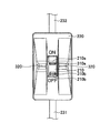
Next, a second embodiment will be described. As shown in FIGS. 21 to 23, the switch device according to the present embodiment is provided with a mountain-shapedconvex portion 120 on both sides of the operation portion 10 in the housing portion 20. The convex portions 120 are provided on both sides of the central portion of the operation unit 10 whose surface is formed in a corrugated shape. 21 is a perspective view of the switch device according to the present embodiment, FIG. 22 is a top view, and FIG. 23 is a side view.
次に、第2の実施の形態について説明する。本実施の形態におけるスイッチ装置は、図21~図23に示されるように、筐体部20において、操作部10の両側に山状の凸部120が設けられている。凸部120は、表面が波形の形状で形成されている操作部10の中央部分の両側に設けられている。図21は本実施の形態におけるスイッチ装置の斜視図であり、図22は上面図であり、図23は側面図である。 [Second Embodiment]
Next, a second embodiment will be described. As shown in FIGS. 21 to 23, the switch device according to the present embodiment is provided with a mountain-shaped
第1の実施の形態では、図12及び図13に示す状態は過渡的ではあるもののオン状態であり、図14~図18に示す状態はオフ状態である。そのため、図12及び図13に示す状態から図14~図18に示す状態に移行する際には、固定接点13aから可動接点12aが離れる。しかし、操作部10の操作は操作部10に直接指を接触させて行なうものであるため、固定接点13aから可動接点12aが離れる前後で指による操作が止められたりすると、チャタリングによりアークが複数回発生したり、アークが長時間発生したりする場合がある。このため、可動接点12aと固定接点13aとの間で発生したアークにより、スイッチ装置が破壊等されてしまう可能性がある。
In the first embodiment, although the states shown in FIGS. 12 and 13 are transient, they are on, and the states shown in FIGS. 14 to 18 are off. Therefore, when the state shown in FIGS. 12 and 13 is shifted to the state shown in FIGS. 14 to 18, the movable contact 12a is separated from the fixed contact 13a. However, since the operation of the operation unit 10 is performed by bringing the finger directly into contact with the operation unit 10, if the operation with the finger is stopped before and after the movable contact 12 a is separated from the fixed contact 13 a, the arc is caused multiple times by chattering. May occur or an arc may occur for a long time. For this reason, the switch device may be destroyed by an arc generated between the movable contact 12a and the fixed contact 13a.
よって、本実施の形態におけるスイッチ装置では、筐体部20において操作部10の両側に凸部120を設けることにより、固定接点13aから可動接点12aが離れる前後で指による操作が途中で止められることを防ぐ構造となっている。これにより、操作部10をより確実に、短時間でオン状態かオフ状態のいずれかにすることができ、スイッチ装置が破壊されること等をより一層防ぐことができる。
Therefore, in the switch device according to the present embodiment, by providing the convex portions 120 on both sides of the operation unit 10 in the casing unit 20, the operation with a finger can be stopped halfway before and after the movable contact 12a is separated from the fixed contact 13a. It has a structure to prevent. As a result, the operation unit 10 can be more reliably brought into either the on state or the off state in a short time, and the switch device can be further prevented from being destroyed.
また、本実施の形態におけるスイッチ装置では、操作部10の一方の端部10a及び他方の端部10bの近傍に操作部凸部110a及び110bが設けられている。このように、操作部凸部110a及び110bを設けることにより、操作部10を操作する指が操作部10の表面で滑ることを防止でき、より一層、固定接点13aから可動接点12aが離れる前後において、指による操作が止められることを防ぐことができる。尚、上記以外の構成については、第1の実施の形態と同様である。
Further, in the switch device according to the present embodiment, operation portion convex portions 110a and 110b are provided in the vicinity of one end portion 10a and the other end portion 10b of the operation portion 10. As described above, by providing the operation portion convex portions 110a and 110b, it is possible to prevent a finger operating the operation portion 10 from slipping on the surface of the operation portion 10, and before and after the movable contact 12a is separated from the fixed contact 13a. It is possible to prevent the operation with the finger from being stopped. The configuration other than the above is the same as that of the first embodiment.
〔第3の実施の形態〕
次に、第3の実施の形態におけるスイッチ装置について、図24~図26に基づき説明する。図24は本実施の形態におけるスイッチ装置の斜視図であり、図25は上面図であり、図26は側面図である。本実施の形態におけるスイッチ装置は第1の実施の形態と同様に波形スイッチであり、波形の操作部210を有している。本実施の形態におけるスイッチ装置は、全体が筐体部220に覆われており、筐体部220に設けられている開口部から操作部210が出ている。また、本実施の形態におけるスイッチ装置には、2本の電源ケーブル231、232が接続されており、一方の電源ケーブル231からは電力、例えば、直流400Vの電力等が供給される。 [Third Embodiment]
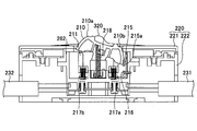
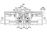
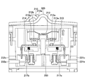
Next, a switch device according to a third embodiment will be described with reference to FIGS. 24 is a perspective view of the switch device according to the present embodiment, FIG. 25 is a top view, and FIG. 26 is a side view. The switch device in the present embodiment is a waveform switch as in the first embodiment, and includes awaveform operation unit 210. The switch device according to the present embodiment is entirely covered with the casing unit 220, and the operation unit 210 protrudes from an opening provided in the casing unit 220. In addition, two power cables 231 and 232 are connected to the switch device in the present embodiment, and power, for example, DC 400V power or the like is supplied from one power cable 231.
次に、第3の実施の形態におけるスイッチ装置について、図24~図26に基づき説明する。図24は本実施の形態におけるスイッチ装置の斜視図であり、図25は上面図であり、図26は側面図である。本実施の形態におけるスイッチ装置は第1の実施の形態と同様に波形スイッチであり、波形の操作部210を有している。本実施の形態におけるスイッチ装置は、全体が筐体部220に覆われており、筐体部220に設けられている開口部から操作部210が出ている。また、本実施の形態におけるスイッチ装置には、2本の電源ケーブル231、232が接続されており、一方の電源ケーブル231からは電力、例えば、直流400Vの電力等が供給される。 [Third Embodiment]
Next, a switch device according to a third embodiment will be described with reference to FIGS. 24 is a perspective view of the switch device according to the present embodiment, FIG. 25 is a top view, and FIG. 26 is a side view. The switch device in the present embodiment is a waveform switch as in the first embodiment, and includes a
操作部210の一方の端部210aまたは他方の端部210bを押下することにより、スイッチのオンまたはオフの制御を行なうことができる。オフ状態から操作部210の一方の端部210aを押下するとオン状態となり、一方の電源ケーブル231と他方の電源ケーブル232とが電気的に接続され電力が供給される。この際、操作部210の他方の端部210bは上に上がる。また、オン状態から操作部210の他方の端部210bを押下するとオフ状態となり、一方の電源ケーブル231と他方の電源ケーブル232との電気的な接続が遮断され電力の供給が停止する。この際、操作部210の一方の端部210aは上に上がる。
By pressing one end 210a or the other end 210b of the operation unit 210, the switch can be controlled to be turned on or off. When one end 210a of the operation unit 210 is pressed from the off state, the operation unit 210 is turned on, and one power cable 231 and the other power cable 232 are electrically connected to supply power. At this time, the other end 210b of the operation unit 210 goes up. When the other end 210b of the operation unit 210 is pressed from the on state, the operation unit 210 is turned off, the electrical connection between the one power cable 231 and the other power cable 232 is cut off, and the supply of power is stopped. At this time, one end 210a of the operation unit 210 rises upward.
尚、本実施の形態におけるスイッチ装置の筐体部220には、図21に示すスイッチと同様に、操作部210の中央部分の両側に山状の凸部320が設けられている。操作部210の操作は、操作部210に指を接触させて行なうため、固定接点から可動接点が離れるに操作が途中で止められた場合には、チャタリングによりアークが複数回発生したり、アークが長時間発生したりする場合がある。このため、可動接点と固定接点との間で発生したアークにより、スイッチ装置が破壊等されてしまう可能性がある。本実施の形態におけるスイッチ装置では、筐体部220において操作部210の両側に凸部320が設けられており、固定接点から可動接点が離れる前後で指による操作が途中で止められることを防ぐ構造となっている。これにより、操作部210をより確実に短時間でオン状態かオフ状態のいずれかにすることができ、スイッチ装置が破壊されること等を防ぐことができる。
It should be noted that, like the switch shown in FIG. 21, mountain-shaped convex portions 320 are provided on both sides of the central portion of the operation unit 210 in the casing unit 220 of the switch device in the present embodiment. The operation of the operation unit 210 is performed by bringing the finger into contact with the operation unit 210. Therefore, when the operation is stopped halfway while the movable contact is separated from the fixed contact, an arc is generated several times by chattering or the arc is generated. It may occur for a long time. For this reason, the switch device may be destroyed by an arc generated between the movable contact and the fixed contact. In the switch device according to the present embodiment, convex portions 320 are provided on both sides of the operation unit 210 in the housing unit 220, and a structure that prevents a finger operation from being stopped halfway before and after the movable contact is separated from the fixed contact. It has become. As a result, the operation unit 210 can be more reliably brought into either the on state or the off state in a short time, and the switch device can be prevented from being destroyed.
また、本実施の形態におけるスイッチ装置では、操作部210の一方の端部210a及び他方の端部210bの近傍に操作部凸部310a及び310bが設けられている。操作部凸部310a及び310bを設けることにより、操作部210の表面で指が滑ることを防止でき、チャタリング等の発生を防ぐことができる。
Further, in the switch device according to the present embodiment, operation portion convex portions 310a and 310b are provided in the vicinity of one end portion 210a and the other end portion 210b of the operation portion 210. By providing the operation portion convex portions 310a and 310b, it is possible to prevent a finger from slipping on the surface of the operation portion 210 and to prevent chattering and the like.
(内部構造)
次に、図27から図29に基づき、本実施の形態におけるスイッチ装置の内部構造を説明する。図27は、本実施の形態におけるスイッチ装置を分解した構造の斜視図であり、図28は、操作部210が設けられている部分の断面図、図29は、固定接点及び可動接点が設けられている部分の断面図である。 (Internal structure)
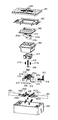
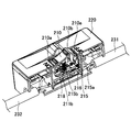
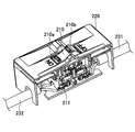
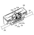
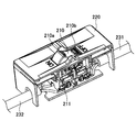
Next, based on FIGS. 27 to 29, the internal structure of the switch device in the present embodiment will be described. 27 is a perspective view of a structure in which the switch device according to the present embodiment is disassembled, FIG. 28 is a cross-sectional view of a portion where theoperation unit 210 is provided, and FIG. 29 is provided with a fixed contact and a movable contact. FIG.
次に、図27から図29に基づき、本実施の形態におけるスイッチ装置の内部構造を説明する。図27は、本実施の形態におけるスイッチ装置を分解した構造の斜視図であり、図28は、操作部210が設けられている部分の断面図、図29は、固定接点及び可動接点が設けられている部分の断面図である。 (Internal structure)
Next, based on FIGS. 27 to 29, the internal structure of the switch device in the present embodiment will be described. 27 is a perspective view of a structure in which the switch device according to the present embodiment is disassembled, FIG. 28 is a cross-sectional view of a portion where the
筐体部220は上部板部221と下部ケース222により形成されている。筐体部220の内部には、内部板部261、操作部210が設置される部分に開口を有する操作部内部カバー262、内部箱部263、操作部210の操作を可動接点部212に伝達するための制御ボタン部211、操作部210をオン状態又はオフ状態を維持するための操作部バネ218、オフ状態において制御ボタン部211を持ち上げる復帰バネ217a、217b、操作部バネ218の下部を支持する操作部バネ支持部材264、オン状態を維持するためのロック部215及びロック部バネ216、永久磁石250を有している。
The housing part 220 is formed by an upper plate part 221 and a lower case 222. The operation of the operation unit inner cover 262, the inner box 263, and the operation unit 210 having an opening in the portion where the operation unit 210 is installed is transmitted to the movable contact unit 212 inside the housing unit 220. A control button unit 211 for operating, an operation unit spring 218 for maintaining the on / off state of the operation unit 210, return springs 217a and 217b for lifting the control button unit 211 in the off state, and a lower portion of the operation unit spring 218. An operation unit spring support member 264, a lock unit 215 and a lock unit spring 216 for maintaining the ON state, and a permanent magnet 250 are provided.
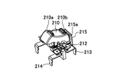
本実施の形態におけるスイッチ装置は、1つの可動接点部212と2つの固定接点部213及び214とが1組のスイッチとなっており、このような組のスイッチが2組設けられている。具体的には、一方の可動接点部212、一方の固定接点部213、一方の固定接点部214により1組のスイッチが形成されており、他方の可動接点部212、他方の固定接点部213、他方の固定接点部214によりもう1組のスイッチが形成されている。
In the switch device according to the present embodiment, one movable contact portion 212 and two fixed contact portions 213 and 214 constitute one set of switches, and two such sets of switches are provided. Specifically, one set of switches is formed by one movable contact portion 212, one fixed contact portion 213, and one fixed contact portion 214, and the other movable contact portion 212, the other fixed contact portion 213, The other fixed contact portion 214 forms another set of switches.
それそれの可動接点部212には2つの可動接点212a、212bが設けられている。また、固定接点部213には固定接点213aが一つ設けられており、固定接点部214には固定接点214aが一つ設けられている。図27図示のスイッチでは、固定接点部213の固定接点213aと可動接点部212の可動接点212aとが接触し、固定接点部214の固定接点214aと可動接点部212の可動接点212bとが接触することにより、固定接点部213と固定接点部214とが、可動接点部212を介し電気的に接続される。これにより、固定接点部213の設けられている側から固定接点部214の設けられている側に電力を供給することができる。尚、可動接点部212、固定接点部213及び214は可動接点212a、212b、固定接点213a、214aを除く全体が導電性を有する板状の銅(Cu)等または銅等を含む金属材料により形成されている。また、可動接点212a、212b、固定接点213a、214aは、銀(Ag)等または銀等を含む材料により形成されている。
Each movable contact portion 212 is provided with two movable contacts 212a and 212b. The fixed contact portion 213 is provided with one fixed contact 213a, and the fixed contact portion 214 is provided with one fixed contact 214a. In the switch shown in FIG. 27, the fixed contact 213a of the fixed contact 213 contacts the movable contact 212a of the movable contact 212, and the fixed contact 214a of the fixed contact 214 contacts the movable contact 212b of the movable contact 212. Thus, the fixed contact portion 213 and the fixed contact portion 214 are electrically connected via the movable contact portion 212. Thereby, electric power can be supplied from the side where the fixed contact portion 213 is provided to the side where the fixed contact portion 214 is provided. Note that the movable contact portion 212 and the fixed contact portions 213 and 214 are made of a conductive plate-like copper (Cu) or a metal material containing copper or the like, except for the movable contacts 212a and 212b and the fixed contacts 213a and 214a. Has been. The movable contacts 212a and 212b and the fixed contacts 213a and 214a are made of silver (Ag) or the like or a material containing silver or the like.
本実施の形態におけるスイッチ装置は、可動接点部212の可動端子212aが固定接点部213の固定接点213aに接触し、可動端子212bが固定接点部214の固定接点214aに接触することによりオン状態となり、接点部が離れることによりオフ状態となる。尚、本実施の形態では、可動接点部212はバネ性を有していなくともよいため厚く形成することができ、可動接点部212の全体を低抵抗、かつ、高い熱容量で形成することができる。このため、例え高電圧の電力を供給する場合にアークが発生した場合であっても、アークにより生じた熱により可動接点部212が変形したり、溶けたりすることはない。
The switch device according to the present embodiment is turned on when the movable terminal 212a of the movable contact portion 212 contacts the fixed contact 213a of the fixed contact portion 213 and the movable terminal 212b contacts the fixed contact 214a of the fixed contact portion 214. When the contact portion is separated, it is turned off. In the present embodiment, the movable contact portion 212 does not have to have a spring property and can be formed thick, and the entire movable contact portion 212 can be formed with low resistance and high heat capacity. . For this reason, even if an arc is generated when supplying high-voltage power, the movable contact portion 212 is not deformed or melted by the heat generated by the arc.
また、上述したように、本実施の形態のスイッチ装置には電源ケーブル231及び232が接続されている。電源ケーブル231は、プラス(+)の電線231aと、マイナス(-)の電線231bと、接地電位(GND)の電線231cとを有している。電源ケーブル232は、プラス(+)の電線232aと、マイナス(-)の電線232bと、接地電位(GND)の電線232cとを有している。
As described above, the power cables 231 and 232 are connected to the switch device of the present embodiment. The power cable 231 includes a plus (+) electric wire 231a, a minus (−) electric wire 231b, and an electric wire 231c having a ground potential (GND). The power cable 232 includes a plus (+) electric wire 232a, a minus (−) electric wire 232b, and an electric wire 232c having a ground potential (GND).
電源ケーブル231のプラス(+)の電線231aは、2つの固定接点部213のうちの一方に接続されており、マイナス(-)の電線231bは2つの固定接点部213のうちの他方に接続されている。また、電源ケーブル232のプラス(+)の電線232aは、2つの固定接点部214のうちの一方に接続されており、マイナス(-)の電線232bは2つの固定接点部214のうちの他方に接続されている。尚、電源ケーブル231における接地電位(GND)の電線231cと電源ケーブル232における接地電位(GND)の電線232cとは、金属材料等により形成されている接続部材234により接続されている。
The positive (+) electric wire 231a of the power cable 231 is connected to one of the two fixed contact portions 213, and the negative (−) electric wire 231b is connected to the other of the two fixed contact portions 213. ing. The positive (+) electric wire 232 a of the power cable 232 is connected to one of the two fixed contact portions 214, and the negative (−) electric wire 232 b is connected to the other of the two fixed contact portions 214. It is connected. The ground potential (GND) electric wire 231c in the power cable 231 and the ground potential (GND) electric wire 232c in the power cable 232 are connected by a connecting member 234 formed of a metal material or the like.
また、本実施の形態におけるスイッチ装置では、直流高電圧に対応するために、電源ケーブル231のプラス(+)の電線231a及びマイナス(-)の電線231b、電源ケーブル232のプラス(+)の電線232a及びマイナス(-)の電線232bは、導体部分の断面積が3.5mm2のものが用いられている。このため、可動接点部212において電源ケーブル231のプラス(+)の電線231a等と同程度以上のコンダクタンスを確保するために、電流が流れる方向に垂直な方向の可動接点部212の断面積は、電源ケーブル231のプラス(+)の電線231a等の導体部分の断面積、即ち3.5mm2以上であることが好ましい。よって、電流が流れる方向に垂直な断面における可動接点部212の幅が7mmの場合には、可動接点部の厚さは0.5mm以上とすることが好ましい。尚、本実施の形態におけるスイッチ装置では、可動接点部212の電流が流れる方向に垂直な断面は、幅が7mm、厚さが1mmの形状で形成されている。
Further, in the switch device according to the present embodiment, in order to cope with the DC high voltage, the plus (+) electric wire 231a and the minus (−) electric wire 231b of the power cable 231 and the plus (+) electric wire of the power cable 232 are used. As the 232a and the minus (−) electric wire 232b, conductors having a cross-sectional area of 3.5 mm 2 are used. For this reason, in order to ensure a conductance at the movable contact portion 212 that is equal to or greater than that of the plus (+) electric wire 231a of the power cable 231, the cross-sectional area of the movable contact portion 212 in the direction perpendicular to the direction of current flow is It is preferable that the cross-sectional area of the conductor portion of the power cable 231 such as the plus (+) electric wire 231a, that is, 3.5 mm 2 or more. Therefore, when the width of the movable contact portion 212 in a cross section perpendicular to the direction in which the current flows is 7 mm, the thickness of the movable contact portion is preferably 0.5 mm or more. In the switch device according to the present embodiment, the cross section perpendicular to the direction in which the current flows through the movable contact portion 212 is formed in a shape having a width of 7 mm and a thickness of 1 mm.
(オンオフ操作)
次に、本実施の形態におけるスイッチ装置のオンオフ操作を説明する。 (On / off operation)
Next, an on / off operation of the switch device according to the present embodiment will be described.
次に、本実施の形態におけるスイッチ装置のオンオフ操作を説明する。 (On / off operation)
Next, an on / off operation of the switch device according to the present embodiment will be described.
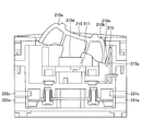
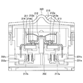
最初に、オン状態について説明する。図30はオフ状態のスイッチ装置の断面図であり、図31(→下向き矢印の説明なし)はオン状態のスイッチ装置の操作部210が設けられている部分の断面図である。図32はオン状態のスイッチの可動接点部212、固定接点部213及び214が設けられている部分の断面図であり、図33はオン状態のスイッチのロック部215が設けられている部分の断面図である。
本実施の形態におけるスイッチ装置の操作部210の下には、図示上下方向に移動可能な制御ボタン部211が設けられている。操作部210の一方の端部210aを押下することにより、操作部回転軸を中心に操作部210が回動し、操作部210により制御ボタン部211が押されて制御ボタン部211が下に移動する。即ち、図30に示すオフ状態から操作部210の一方の端部210aを押下することにより、スイッチ装置は図31乃至図33に示すオン状態となる。 First, the on state will be described. FIG. 30 is a cross-sectional view of the switch device in the off state, and FIG. 31 (→ no explanation of the downward arrow) is a cross-sectional view of a portion where theoperation unit 210 of the switch device in the on state is provided. 32 is a cross-sectional view of a portion where the movable contact portion 212 and fixed contact portions 213 and 214 of the switch in the on state are provided, and FIG. 33 is a cross section of a portion where the lock portion 215 of the switch in the on state is provided. FIG.
Below theoperation unit 210 of the switch device in the present embodiment, there is provided a control button unit 211 that is movable in the illustrated vertical direction. By depressing one end 210a of the operation unit 210, the operation unit 210 rotates around the rotation axis of the operation unit, the control button unit 211 is pushed by the operation unit 210, and the control button unit 211 moves downward. To do. That is, when the one end portion 210a of the operation unit 210 is pressed from the off state shown in FIG. 30, the switch device is turned on as shown in FIGS.
本実施の形態におけるスイッチ装置の操作部210の下には、図示上下方向に移動可能な制御ボタン部211が設けられている。操作部210の一方の端部210aを押下することにより、操作部回転軸を中心に操作部210が回動し、操作部210により制御ボタン部211が押されて制御ボタン部211が下に移動する。即ち、図30に示すオフ状態から操作部210の一方の端部210aを押下することにより、スイッチ装置は図31乃至図33に示すオン状態となる。 First, the on state will be described. FIG. 30 is a cross-sectional view of the switch device in the off state, and FIG. 31 (→ no explanation of the downward arrow) is a cross-sectional view of a portion where the
Below the
制御ボタン部211は可動接点部212を支持しており、図30の状態から操作部210の一方の端部210aを押すことにより、操作部210が操作部回転軸を中心に回転し、制御ボタン押下部210dにより制御ボタン部211が図31図示矢印方向に押され、制御ボタン部211は下に移動する。これに伴い可動接点部212も下に移動し、図32に示すように可動接点部212の可動接点212aは固定接点部213の固定接点213aと接触し、同様に、可動接点212bは固定接点214aと接触する。これにより、固定接点部213と固定接点部214とが可動接点部212を介し電気的に接続されて、オン状態となる。
The control button portion 211 supports the movable contact portion 212. By pressing one end portion 210a of the operation portion 210 from the state shown in FIG. 30, the operation portion 210 rotates around the operation portion rotation axis, and the control button The control button unit 211 is pushed in the direction of the arrow in FIG. 31 by the pressing unit 210d, and the control button unit 211 moves downward. Along with this, the movable contact portion 212 also moves downward, and as shown in FIG. 32, the movable contact 212a of the movable contact portion 212 contacts the fixed contact 213a of the fixed contact portion 213, and similarly, the movable contact 212b is fixed contact 214a. Contact with. Thereby, the fixed contact part 213 and the fixed contact part 214 are electrically connected via the movable contact part 212, and it will be in an ON state.
オン状態では、電源ケーブル231のプラス(+)の電線231aと、電源ケーブル232のプラス(+)の電線232aとが電気的に接続され、電源ケーブル231のマイナス(-)の電線231bと、電源ケーブル232のマイナス(-)の電線232bとが電気的に接続される。これにより、電源ケーブル231から電源ケーブル232に電力が供給される。
In the ON state, the plus (+) wire 231a of the power cable 231 and the plus (+) wire 232a of the power cable 232 are electrically connected, and the minus (−) wire 231b of the power cable 231 is connected to the power source. The minus (−) electric wire 232b of the cable 232 is electrically connected. As a result, power is supplied from the power cable 231 to the power cable 232.
より詳細に、本実施の形態におけるスイッチ装置のオン状態を、図34から図36を加えて説明する。図34は、スイッチ装置がオン状態である場合の断面の斜視図であり、図35は、オン状態である場合の図34とは異なる部分における断面の斜視図である。図36は、スイッチ装置がオン状態である場合の操作部を含む要部の斜視図である。
More specifically, the ON state of the switch device in the present embodiment will be described with reference to FIGS. FIG. 34 is a perspective view of a cross section when the switch device is in an on state, and FIG. 35 is a perspective view of a cross section in a portion different from FIG. 34 when the switch device is in an on state. FIG. 36 is a perspective view of the main part including the operation unit when the switch device is in the ON state.
本実施の形態におけるスイッチ装置は、図30に示すオフ状態から操作部210の一方の端部210aを押下することにより図31~図33に示すオン状態となり、操作部バネ218の力によりオン状態が維持される。尚、図34においては便宜上、操作部バネ218はまっすぐに記載されているが、操作部210の一方の端部210aを押下することにより操作部バネ218は逆「く」の字状に曲がり、スイッチ装置のオン状態が維持される。
この際、図30に示すロック部215のロック部接触部215aと操作部210の側面接触部210eとの接触が離れるため、ロック部215がロック部バネ216の復元力により押されて、図33に示す矢印方向に移動し、ロック部215の先端部分の突起部215bが制御ボタン部211のL字状の引っ掛け部211bに係合する。図33の状態においては、制御ボタン部211は、引っ掛け部211bに係合している突起部215bによりロックされるため図33図示上方向には移動せず、操作部210が操作部回転軸を中心に若干移動したとしても、可動接点212aと固定接点213aとの接触状態及び可動接点212bと固定接点214aとの接触状態は保たれ、オン状態は維持される。尚、本実施の形態におけるスイッチ装置には、制御ボタン部211に接続されている復帰バネ217a及び217bが設けられており、オン状態においては、制御ボタン部211により復帰バネ217a及び217bが押され縮んだ状態となっている。 The switch device according to the present embodiment is turned on as shown in FIGS. 31 to 33 by depressing oneend 210a of the operation unit 210 from the off state shown in FIG. 30, and is turned on by the force of the operation unit spring 218. Is maintained. In FIG. 34, the operating portion spring 218 is shown straight for convenience, but when the one end portion 210a of the operating portion 210 is pressed, the operating portion spring 218 bends in a reverse “<” shape. The on state of the switch device is maintained.
At this time, since the contact between the lockportion contact portion 215a of the lock portion 215 shown in FIG. 30 and the side surface contact portion 210e of the operation portion 210 is separated, the lock portion 215 is pushed by the restoring force of the lock portion spring 216, and FIG. The protrusion 215b at the tip of the lock portion 215 engages with the L-shaped hook portion 211b of the control button portion 211. In the state of FIG. 33, the control button portion 211 is locked by the projection 215b engaged with the hook portion 211b, and therefore does not move in the upward direction in FIG. Even if it moves slightly to the center, the contact state between the movable contact 212a and the fixed contact 213a and the contact state between the movable contact 212b and the fixed contact 214a are maintained, and the ON state is maintained. Note that the switch device according to the present embodiment is provided with return springs 217a and 217b connected to the control button unit 211. In the on state, the return springs 217a and 217b are pushed by the control button unit 211. It is in a contracted state.
この際、図30に示すロック部215のロック部接触部215aと操作部210の側面接触部210eとの接触が離れるため、ロック部215がロック部バネ216の復元力により押されて、図33に示す矢印方向に移動し、ロック部215の先端部分の突起部215bが制御ボタン部211のL字状の引っ掛け部211bに係合する。図33の状態においては、制御ボタン部211は、引っ掛け部211bに係合している突起部215bによりロックされるため図33図示上方向には移動せず、操作部210が操作部回転軸を中心に若干移動したとしても、可動接点212aと固定接点213aとの接触状態及び可動接点212bと固定接点214aとの接触状態は保たれ、オン状態は維持される。尚、本実施の形態におけるスイッチ装置には、制御ボタン部211に接続されている復帰バネ217a及び217bが設けられており、オン状態においては、制御ボタン部211により復帰バネ217a及び217bが押され縮んだ状態となっている。 The switch device according to the present embodiment is turned on as shown in FIGS. 31 to 33 by depressing one
At this time, since the contact between the lock
次に、オン状態からオフ状態に移行する途中の段階を、図37に基づき説明する。
Next, the stage during the transition from the on state to the off state will be described with reference to FIG.
本実施の形態におけるスイッチ装置は、図31等に示すオン状態から操作部210の他方の端部210bを押下すると、操作部回転軸を中心に操作部210が回動し、過渡的な状態として図37に示す状態となる。この状態では、操作部210の制御ボタン押下部210dと制御ボタン部211とは接触していないが、図37図示左向きに付勢されているロック部215の突起部215bは制御ボタン部211の引っ掛け部211bと係合している状態にあるため、制御ボタン部211は固定されており上に移動することはなく、可動接点212aと固定接点213aとの接触及び可動接点212bと固定接点214aとの接触が保たれる。よって、スイッチ装置のオン状態が維持される。尚、この状態においては、操作部210の側面接触部210eとロック部215のロック部接触部215aとが接触していない状態、または、操作部210の側面接触部210eによりロック部接触部215aが押されていない状態にある。
In the switch device according to the present embodiment, when the other end portion 210b of the operation unit 210 is pressed from the ON state illustrated in FIG. 31 or the like, the operation unit 210 rotates around the operation unit rotation axis, and a transitional state is established. The state shown in FIG. 37 is obtained. In this state, the control button pressing unit 210d of the operation unit 210 and the control button unit 211 are not in contact, but the protrusion 215b of the lock unit 215 that is biased to the left in FIG. Since the control button portion 211 is fixed and does not move upward because it is engaged with the portion 211b, the contact between the movable contact 212a and the fixed contact 213a and the contact between the movable contact 212b and the fixed contact 214a. Contact is maintained. Therefore, the ON state of the switch device is maintained. In this state, the side surface contact portion 210e of the operation portion 210 and the lock portion contact portion 215a of the lock portion 215 are not in contact, or the lock portion contact portion 215a is moved by the side surface contact portion 210e of the operation portion 210. It is not pressed.
次に、オフ状態について、図30、図38から図42に基づき説明する。図38は、オフ状態のスイッチ装置の可動接点部212、固定接点部213及び214が設けられている部分の断面図であり、図39は、オフ状態のスイッチ装置のロック部215が設けられている部分の断面図である。図40は、スイッチ装置がオフ状態である場合の断面の斜視図であり、図41は、オフ状態である場合の図40とは異なる部分における断面の斜視図である。図42は、スイッチ装置がオフ状態である場合の操作部を含む要部の斜視図である。
Next, the off state will be described with reference to FIGS. 30 and 38 to 42. FIG. 38 is a cross-sectional view of a portion where the movable contact portion 212 and the fixed contact portions 213 and 214 of the switch device in the off state are provided, and FIG. 39 is a diagram illustrating the case where the lock portion 215 of the switch device in the off state is provided. FIG. 40 is a perspective view of a cross section when the switch device is in an off state, and FIG. 41 is a perspective view of a cross section in a portion different from that in FIG. 40 when the switch device is in an off state. FIG. 42 is a perspective view of the main part including the operation unit when the switch device is in the OFF state.
本実施の形態におけるスイッチ装置は、図37に示す状態より更に操作部210の他方の端部210bを押下することによりオフ状態となる。オフ状態は操作部バネ218の力により維持される。尚、図40においては便宜上、操作部バネ218はまっすぐに記載されているが、操作部210の他方の端部210bを押下することにより「く」の字状に曲がり、オフ状態が維持される。
The switch device according to the present embodiment is turned off by further pressing the other end 210b of the operation unit 210 from the state shown in FIG. The off state is maintained by the force of the operation portion spring 218. In FIG. 40, the operating portion spring 218 is shown straight for convenience. However, when the other end portion 210b of the operating portion 210 is pressed, the operating portion spring 218 is bent into a "<" shape and the off state is maintained. .
図37に示す過渡的な状態から、操作部210の他方の端部210bを更に押下することにより、操作部回転軸を中心に操作部210が更に回動する。操作部210が回動することにより、図30に示されるように、操作部210の側面接触部210eとロック部215のロック部接触部215aとが接触し、ロック部バネ216の復元力に抗して側面接触部210eによりロック部接触部215aが図30図示右側に押される。これにより、ロック部215は、図30において図示右方向に移動し、図39に示すようにロック部215の突起部215bが制御ボタン部211の引っ掛け部211bより離れてロック部215によるロックが解除され、制御ボタン部211は復帰バネ217a及び217bの復元力により図39に示す矢印方向に持ち上げられる。このようにして、可動接点部212が固定接点部213及び214の側から図38図示矢印方向に離れるため、可動接点部212の可動接点212aと固定接点部213の固定接点213aとが離れ、可動接点部212の可動接点212bと固定接点部214の固定接点214aとが離れる。このように、復帰バネ217a及び217bの復元力によりスイッチがオン状態からオフ状態となるため、短時間でオフ状態とすることができる。
37, when the other end 210b of the operation unit 210 is further pressed from the transitional state shown in FIG. 37, the operation unit 210 further rotates about the operation unit rotation axis. When the operation unit 210 is rotated, as shown in FIG. 30, the side surface contact part 210 e of the operation unit 210 and the lock part contact part 215 a of the lock part 215 come into contact with each other and resist the restoring force of the lock part spring 216. Then, the lock portion contact portion 215a is pushed to the right side in FIG. 30 by the side surface contact portion 210e. As a result, the lock portion 215 moves in the right direction in FIG. 30, and the protrusion 215b of the lock portion 215 is separated from the hook portion 211b of the control button portion 211 to release the lock by the lock portion 215 as shown in FIG. Then, the control button portion 211 is lifted in the arrow direction shown in FIG. 39 by the restoring force of the return springs 217a and 217b. In this way, since the movable contact portion 212 is separated from the fixed contact portions 213 and 214 in the direction of the arrow in FIG. 38, the movable contact 212a of the movable contact portion 212 and the fixed contact 213a of the fixed contact portion 213 are separated and movable. The movable contact 212b of the contact portion 212 and the fixed contact 214a of the fixed contact portion 214 are separated. In this way, the switch is turned from the on state to the off state by the restoring force of the return springs 217a and 217b, so that the switch can be turned off in a short time.
本実施の形態におけるスイッチ装置では、復帰バネ217a及び217bの復元力により、極めて短い時間でオン状態からオフ状態にできるため、可動接点212aと固定接点213aとの間及び可動接点212bと固定接点214aとの間においてアークが発生しない、または、発生しても極めて短時間である。従って、可動接点部12が溶けること等によりスイッチ装置が破壊されることはない。
In the switch device according to the present embodiment, the restoring force of the return springs 217a and 217b can be changed from the on state to the off state in an extremely short time, and therefore, between the movable contact 212a and the fixed contact 213a and between the movable contact 212b and the fixed contact 214a. An arc does not occur between them, or even if it occurs, it is a very short time. Therefore, the switch device is not destroyed by melting the movable contact portion 12 or the like.
(アーク遮断機能)
本実施の形態におけるスイッチ装置では、可動接点212aと固定接点213aとの間、または可動接点212bと固定接点214aとの間で発生したアークを瞬時に遮断する機能が設けられている。
本実施の形態におけるスイッチ装置には、可動接点部212の下であって固定接点部213と固定接点部214の間に永久磁石250が設けられており、永久磁石250により発生した磁界により、可動接点212aと固定接点213aとの間で発生したアーク、可動接点212bと固定接点214aとの間で発生したアークを瞬時に消弧させることができる。本実施の形態におけるスイッチ装置においては、可動接点212aと固定接点213aとの間及び可動接点212bと固定接点214aとの間において効率よく磁界が印加されるように、可動接点部212の下であって、固定接点部213と固定接点部214の間に、永久磁石250が設けられている。 (Arc break function)
The switch device according to the present embodiment is provided with a function of instantaneously interrupting an arc generated between themovable contact 212a and the fixed contact 213a or between the movable contact 212b and the fixed contact 214a.
In the switch device according to the present embodiment, apermanent magnet 250 is provided below the movable contact portion 212 and between the fixed contact portion 213 and the fixed contact portion 214, and is movable by a magnetic field generated by the permanent magnet 250. The arc generated between the contact 212a and the fixed contact 213a and the arc generated between the movable contact 212b and the fixed contact 214a can be extinguished instantaneously. In the switch device according to the present embodiment, a magnetic field is efficiently applied between the movable contact 212a and the fixed contact 213a and between the movable contact 212b and the fixed contact 214a. A permanent magnet 250 is provided between the fixed contact portion 213 and the fixed contact portion 214.
本実施の形態におけるスイッチ装置では、可動接点212aと固定接点213aとの間、または可動接点212bと固定接点214aとの間で発生したアークを瞬時に遮断する機能が設けられている。
本実施の形態におけるスイッチ装置には、可動接点部212の下であって固定接点部213と固定接点部214の間に永久磁石250が設けられており、永久磁石250により発生した磁界により、可動接点212aと固定接点213aとの間で発生したアーク、可動接点212bと固定接点214aとの間で発生したアークを瞬時に消弧させることができる。本実施の形態におけるスイッチ装置においては、可動接点212aと固定接点213aとの間及び可動接点212bと固定接点214aとの間において効率よく磁界が印加されるように、可動接点部212の下であって、固定接点部213と固定接点部214の間に、永久磁石250が設けられている。 (Arc break function)
The switch device according to the present embodiment is provided with a function of instantaneously interrupting an arc generated between the
In the switch device according to the present embodiment, a
以上、本発明の好ましい実施形態について詳述したが、本発明は上記した特定の実施形態に限定されるものではなく、特許請求の範囲に記載された本発明の要旨の範囲内において、種々の変形・変更が可能なものである。
The preferred embodiments of the present invention have been described in detail above. However, the present invention is not limited to the specific embodiments described above, and various modifications are possible within the scope of the gist of the present invention described in the claims. It can be modified and changed.
本願は2012年10月4日に出願した日本国特許出願第2012-222552号に基づきその優先権を主張するものであり、同日本国出願の全内容を参照することにより本願に援用する。
The present application claims priority based on Japanese Patent Application No. 2012-2225552 filed on October 4, 2012, and is incorporated herein by reference in its entirety.
The present application claims priority based on Japanese Patent Application No. 2012-2225552 filed on October 4, 2012, and is incorporated herein by reference in its entirety.
10 操作部
10a 一方の端部
10b 他方の端部
10c 操作部回転軸
10d ロック解除凸部
11 制御ボタン部
11a 制御ボタン部回転軸
11b 可動端子支持部
11c 引っ掛け部
12 可動接点部
12a 可動接点
13 固定接点部
13a 固定接点
14 操作部バネ
15 ロック部
15a 第1の突起部
15b 第2の突起部
16 ロック部バネ
17 復帰バネ
20 筐体部
31 電源ケーブル
31a プラス(+)の電線
31b マイナス(-)の電線
31c GNDの電線
32 電源ケーブル
32a プラス(+)の電線
32b マイナス(-)の電線
32c GNDの電線
40 基板
50 永久磁石 DESCRIPTION OFSYMBOLS 10 Operation part 10a One end part 10b The other end part 10c Operation part rotating shaft 10d Unlocking convex part 11 Control button part 11a Control button part rotating shaft 11b Movable terminal support part 11c Hook part 12 Movable contact part 12a Movable contact 13 Fixed Contact portion 13a Fixed contact 14 Operation portion spring 15 Lock portion 15a First projection portion 15b Second projection portion 16 Lock portion spring 17 Return spring 20 Housing portion 31 Power supply cable 31a Positive (+) wire 31b Negative (-) Wire 31c GND wire 32 Power cable 32a Plus (+) wire 32b Minus (-) wire 32c GND wire 40 Substrate 50 Permanent magnet
10a 一方の端部
10b 他方の端部
10c 操作部回転軸
10d ロック解除凸部
11 制御ボタン部
11a 制御ボタン部回転軸
11b 可動端子支持部
11c 引っ掛け部
12 可動接点部
12a 可動接点
13 固定接点部
13a 固定接点
14 操作部バネ
15 ロック部
15a 第1の突起部
15b 第2の突起部
16 ロック部バネ
17 復帰バネ
20 筐体部
31 電源ケーブル
31a プラス(+)の電線
31b マイナス(-)の電線
31c GNDの電線
32 電源ケーブル
32a プラス(+)の電線
32b マイナス(-)の電線
32c GNDの電線
40 基板
50 永久磁石 DESCRIPTION OF
Claims (11)
- 固定接点を含む固定接点部と、
可動接点を含む可動接点部と、
引っ掛け部を含み、前記可動接点部を支持する制御ボタン部と、
第1の端部と第2の端部を含む操作部と、
第1の突起部と第2の突起部を含むロック部とを備え、
前記第1の端部の押下により前記制御ボタン部が前記操作部によって押されて前記可動接点が前記固定接点に接触してオン状態となり、前記第2の端部の押下により前記可動接点が前記固定接点から離れてオフ状態となり、
前記可動接点と前記固定接点とが接触している状態では、前記制御ボタン部の前記引っ掛け部に前記ロック部の前記第1の突起部が接触して前記制御ボタン部の移動が規制されてオン状態が維持され、
前記第2の端部の押下により、前記操作部が前記ロック部の前記第2の突起部に接触して、前記引っ掛け部から前記第1の突起部が離れるように前記ロック部が移動し、オフ状態となることを特徴とするスイッチ装置。 A fixed contact portion including a fixed contact;
A movable contact portion including a movable contact;
A control button part including a hook part and supporting the movable contact part;
An operation unit including a first end and a second end;
A lock portion including a first protrusion and a second protrusion;
When the first end is pressed, the control button part is pressed by the operation unit, and the movable contact comes into contact with the stationary contact, and when the second end is pressed, the movable contact is turned on. It goes off from the fixed contact,
In a state where the movable contact and the fixed contact are in contact with each other, the first protrusion of the lock portion comes into contact with the hook portion of the control button portion, and the movement of the control button portion is restricted and turned on. State is maintained,
By pressing the second end, the operation unit comes into contact with the second projection of the lock unit, and the lock unit moves so that the first projection is separated from the hook unit, A switching device that is turned off. - 前記オン状態から前記オフ状態に移行する際、前記操作部と前記制御ボタン部との接触が離れても、前記引っ掛け部に前記第1の突起部が接触してオン状態が維持されるものであることを特徴とする請求項1に記載のスイッチ装置。 When shifting from the on state to the off state, even if the operation unit and the control button unit are separated from each other, the first protrusion is brought into contact with the hook and the on state is maintained. The switch device according to claim 1, wherein the switch device is provided.
- 前記制御ボタン部に接しており、前記制御ボタン部を前記オン状態から前記オフ状態に移動する方向に復元力を有する復帰バネを有することを特徴とする請求項1に記載のスイッチ装置。 The switch device according to claim 1, further comprising a return spring that is in contact with the control button portion and has a restoring force in a direction in which the control button portion is moved from the on state to the off state.
- 前記制御ボタン部の前記引っ掛け部が設けられている側に、前記ロック部を移動させる方向に復元力を有するロック部バネを有することを特徴とする請求項1に記載のスイッチ装置。 The switch device according to claim 1, further comprising: a lock portion spring having a restoring force in a direction in which the lock portion is moved on a side of the control button portion where the hook portion is provided.
- 前記操作部が露出する開口部を有する筐体部をさらに備え、
前記筐体部において前記操作部の中央部分の両側となる部分には、凸部が設けられていることを特徴とする請求項1に記載のスイッチ装置。 A housing portion having an opening through which the operation portion is exposed;
The switch device according to claim 1, wherein convex portions are provided on portions of the housing portion that are on both sides of a central portion of the operation portion. - それぞれ固定接点を含む2つの固定接点部と、
2つの可動接点を含む可動接点部と、
引っ掛け部を含む制御ボタン部と、
第1の端部及び第2の端部と、接触部を含む操作部と、
突起部を含むロック部とを備え、
前記可動接点部は前記制御ボタン部に接触しており、前記第1の端部の押下により前記制御ボタン部が押され、各々の可動接点が対応する前記固定接点に接触してオン状態となり、前記第2の端部の押下により前記可動接点が前記固定接点から離れてオフ状態となり、
前記可動接点と前記固定接点とが接触している状態では、前記引っ掛け部に、前記突起部が接触してオン状態が維持され、
前記第2の端部の押下により、前記接触部により前記ロック部が押されて移動し、前記引っ掛け部から前記突起部が離れ、オフ状態となることを特徴とするスイッチ装置。 Two fixed contact sections each including a fixed contact;
A movable contact portion including two movable contacts;
A control button part including a hook part,
A first end and a second end; and an operation unit including a contact part;
Including a locking portion including a protrusion,
The movable contact portion is in contact with the control button portion, the control button portion is pushed by depressing the first end, and each movable contact comes into contact with the corresponding fixed contact, and is turned on. When the second end is pressed, the movable contact is separated from the fixed contact and turned off,
In the state where the movable contact and the fixed contact are in contact, the protrusion is in contact with the hooking portion, and the on state is maintained.
When the second end portion is pressed, the lock portion is pushed and moved by the contact portion, and the projection portion is separated from the hook portion to be turned off. - 前記オン状態から前記オフ状態に移行する際、
前記操作部と前記制御ボタン部との接触が離れても、前記引っ掛け部に前記突起部が接触しており、オン状態が維持されていることを特徴とする請求項6に記載のスイッチ装置。 When transitioning from the on state to the off state,
7. The switch device according to claim 6, wherein, even if the operation unit and the control button unit are separated from each other, the projection is in contact with the hook and the on state is maintained. - 前記制御ボタン部に接しており、前記制御ボタン部を前記オン状態から前記オフ状態に移動する方向に復元力を有する復帰バネを有することを特徴とする請求項6に記載のスイッチ装置。 The switch device according to claim 6, further comprising a return spring that is in contact with the control button part and has a restoring force in a direction in which the control button part is moved from the on state to the off state.
- 前記制御ボタン部の前記引っ掛け部が設けられている側に、前記ロック部を移動させる方向に復元力を有するロック部バネを有することを特徴とする請求項6に記載のスイッチ装置。 The switch device according to claim 6, further comprising: a lock portion spring having a restoring force in a direction in which the lock portion is moved on a side of the control button portion where the hook portion is provided.
- 2つの前記固定接点の間には、前記固定接点と前記可動接点との間に磁界を印加する磁石を有することを特徴とする請求項6に記載のスイッチ装置。 The switch device according to claim 6, further comprising a magnet that applies a magnetic field between the fixed contact and the movable contact between the two fixed contacts.
- 開口部を有する筐体部をさらに備え、
前記操作部は、前記筐体部の前記開口部より出ており、
前記筐体部において前記操作部の中央部分の両側となる部分には、凸部が設けられていることを特徴とする請求項6に記載のスイッチ装置。 It further comprises a casing having an opening,
The operation part is protruding from the opening of the housing part,
The switch device according to claim 6, wherein convex portions are provided on portions of the housing portion that are on both sides of a central portion of the operation portion.
Priority Applications (2)
| Application Number | Priority Date | Filing Date | Title |
|---|---|---|---|
| CN201380052771.9A CN104704591B (en) | 2012-10-04 | 2013-10-01 | Switching device |
| US14/430,951 US9607793B2 (en) | 2012-10-04 | 2013-10-01 | Switch |
Applications Claiming Priority (2)
| Application Number | Priority Date | Filing Date | Title |
|---|---|---|---|
| JP2012222552A JP5961517B2 (en) | 2012-10-04 | 2012-10-04 | Switch device |
| JP2012-222552 | 2012-10-04 |
Publications (1)
| Publication Number | Publication Date |
|---|---|
| WO2014054654A1 true WO2014054654A1 (en) | 2014-04-10 |
Family
ID=50434978
Family Applications (1)
| Application Number | Title | Priority Date | Filing Date |
|---|---|---|---|
| PCT/JP2013/076734 WO2014054654A1 (en) | 2012-10-04 | 2013-10-01 | Switch device |
Country Status (4)
| Country | Link |
|---|---|
| US (1) | US9607793B2 (en) |
| JP (1) | JP5961517B2 (en) |
| CN (1) | CN104704591B (en) |
| WO (1) | WO2014054654A1 (en) |
Families Citing this family (7)
| Publication number | Priority date | Publication date | Assignee | Title |
|---|---|---|---|---|
| US10163586B2 (en) * | 2016-11-04 | 2018-12-25 | Honeywell International Inc. | Momentary structure for mini toggle switch |
| TWI681432B (en) * | 2018-07-03 | 2020-01-01 | 易湘雲 | Switch with thermal breaker and power socket comprising such switch |
| TWI677146B (en) * | 2018-07-03 | 2019-11-11 | 易湘雲 | Switch with thermal breaker and power socket comprising such switch |
| TWI674610B (en) * | 2018-07-03 | 2019-10-11 | 易湘雲 | Push button switch and conductor sheet thereof |
| TWI676200B (en) * | 2018-07-03 | 2019-11-01 | 易湘雲 | Switch with thermal breaker and power socket comprising such switch |
| TWI674612B (en) * | 2018-07-03 | 2019-10-11 | 易湘雲 | Method for interrupting power supply to overheating power switch or utilization equipment |
| TWI676201B (en) * | 2018-07-03 | 2019-11-01 | 易湘雲 | Switch with thermal breaker and power socket comprising such switch |
Citations (3)
| Publication number | Priority date | Publication date | Assignee | Title |
|---|---|---|---|---|
| JPS53139185A (en) * | 1977-05-11 | 1978-12-05 | Ellenberger & Poensgen | Breaker |
| JPS5681453U (en) * | 1979-11-28 | 1981-07-01 | ||
| JPH0160430U (en) * | 1987-10-09 | 1989-04-17 |
Family Cites Families (5)
| Publication number | Priority date | Publication date | Assignee | Title |
|---|---|---|---|---|
| DE9401785U1 (en) * | 1994-02-03 | 1995-07-20 | Kloeckner Moeller Gmbh | Key switch with a locking mechanism |
| DE69707867T2 (en) * | 1997-09-15 | 2002-04-11 | Signal Lux Italia Spa | Switching device for electrical circuits |
| DE19819242B4 (en) * | 1998-04-29 | 2005-11-10 | Ge Power Controls Polska Sp.Z.O.O. | Thermomagnetic circuit breaker |
| JP3704021B2 (en) | 2000-04-18 | 2005-10-05 | アルプス電気株式会社 | Switch device |
| CN202650936U (en) * | 2012-07-09 | 2013-01-02 | 上汽依维柯红岩商用车有限公司 | Rocker switch |
-
2012
- 2012-10-04 JP JP2012222552A patent/JP5961517B2/en active Active
-
2013
- 2013-10-01 CN CN201380052771.9A patent/CN104704591B/en not_active Expired - Fee Related
- 2013-10-01 US US14/430,951 patent/US9607793B2/en active Active
- 2013-10-01 WO PCT/JP2013/076734 patent/WO2014054654A1/en active Application Filing
Patent Citations (3)
| Publication number | Priority date | Publication date | Assignee | Title |
|---|---|---|---|---|
| JPS53139185A (en) * | 1977-05-11 | 1978-12-05 | Ellenberger & Poensgen | Breaker |
| JPS5681453U (en) * | 1979-11-28 | 1981-07-01 | ||
| JPH0160430U (en) * | 1987-10-09 | 1989-04-17 |
Also Published As
| Publication number | Publication date |
|---|---|
| CN104704591A (en) | 2015-06-10 |
| JP2014075290A (en) | 2014-04-24 |
| US9607793B2 (en) | 2017-03-28 |
| JP5961517B2 (en) | 2016-08-02 |
| US20150287558A1 (en) | 2015-10-08 |
| CN104704591B (en) | 2016-12-07 |
Similar Documents
| Publication | Publication Date | Title |
|---|---|---|
| WO2014054654A1 (en) | Switch device | |
| AU612208B2 (en) | Electric switch with counteracting electro-dynamic forces | |
| CN103545153B (en) | Protection switch device and yoke | |
| KR101581182B1 (en) | Bi-direction Switching Device for using DC current with permanent magnet | |
| KR102327043B1 (en) | electrical contact system | |
| JP4343180B2 (en) | Sequential trip circuit breaker using PTC current limiting element | |
| MX2012015027A (en) | Quad break modular circuit breaker interrupter. | |
| US5351024A (en) | Electrical contactor and interrupter employing a rotary disc | |
| JP2012164653A (en) | Vacuum interrupter for vacuum circuit breaker | |
| JP2012138173A (en) | Circuit breaker | |
| CN104903985A (en) | Switching device | |
| KR101036485B1 (en) | Contactor assembly for current limitable circuit breaker | |
| CN213936096U (en) | Circuit breaker | |
| CN101562103A (en) | Circuit breaker with improved close and latch performance | |
| CN102623265A (en) | Circuit interruption device and method of assembly | |
| US20200098531A1 (en) | Electrical Contact System | |
| CN115104168A (en) | Switching device | |
| JP2009164001A (en) | Switching device | |
| KR20040080917A (en) | Circuit Breaker | |
| KR101721106B1 (en) | Circuit breaker | |
| US20180019553A1 (en) | Connector | |
| JP5566251B2 (en) | relay | |
| JP7187272B2 (en) | circuit breaker | |
| CN209708929U (en) | The contact system of low-voltage circuit breaker | |
| JP7133986B2 (en) | circuit breaker |
Legal Events
| Date | Code | Title | Description |
|---|---|---|---|
| 121 | Ep: the epo has been informed by wipo that ep was designated in this application |
Ref document number: 13843720 Country of ref document: EP Kind code of ref document: A1 |
|
| WWE | Wipo information: entry into national phase |
Ref document number: 14430951 Country of ref document: US |
|
| NENP | Non-entry into the national phase |
Ref country code: DE |
|
| 122 | Ep: pct application non-entry in european phase |
Ref document number: 13843720 Country of ref document: EP Kind code of ref document: A1 |