WO2014051041A1 - Pipe inner-layer structure, and connection member used therein - Google Patents
Pipe inner-layer structure, and connection member used therein Download PDFInfo
- Publication number
- WO2014051041A1 WO2014051041A1 PCT/JP2013/076234 JP2013076234W WO2014051041A1 WO 2014051041 A1 WO2014051041 A1 WO 2014051041A1 JP 2013076234 W JP2013076234 W JP 2013076234W WO 2014051041 A1 WO2014051041 A1 WO 2014051041A1
- Authority
- WO
- WIPO (PCT)
- Prior art keywords
- connecting member
- pipe
- surface material
- fitting
- layer structure
- Prior art date
Links
Images


Classifications
-
- F—MECHANICAL ENGINEERING; LIGHTING; HEATING; WEAPONS; BLASTING
- F16—ENGINEERING ELEMENTS AND UNITS; GENERAL MEASURES FOR PRODUCING AND MAINTAINING EFFECTIVE FUNCTIONING OF MACHINES OR INSTALLATIONS; THERMAL INSULATION IN GENERAL
- F16L—PIPES; JOINTS OR FITTINGS FOR PIPES; SUPPORTS FOR PIPES, CABLES OR PROTECTIVE TUBING; MEANS FOR THERMAL INSULATION IN GENERAL
- F16L55/00—Devices or appurtenances for use in, or in connection with, pipes or pipe systems
- F16L55/16—Devices for covering leaks in pipes or hoses, e.g. hose-menders
- F16L55/162—Devices for covering leaks in pipes or hoses, e.g. hose-menders from inside the pipe
- F16L55/165—Devices for covering leaks in pipes or hoses, e.g. hose-menders from inside the pipe a pipe or flexible liner being inserted in the damaged section
-
- E—FIXED CONSTRUCTIONS
- E03—WATER SUPPLY; SEWERAGE
- E03F—SEWERS; CESSPOOLS
- E03F3/00—Sewer pipe-line systems
- E03F3/06—Methods of, or installations for, laying sewer pipes
- E03F2003/065—Refurbishing of sewer pipes, e.g. by coating, lining
Definitions
- the present invention relates to an inner layer structure of a pipe and a connecting member used therefor, and more particularly to an inner layer structure of a pipe suitable for repairing an existing pipe having a relatively large diameter such as a sewer pipe and a connecting member used therefor.
- Patent Documents 1 and 2 Conventionally, many repair structures for existing pipes that cover the entire inner surface of the existing pipe with a lining material have been proposed as repair structures for existing pipes such as sewer pipes (see, for example, Patent Documents 1 and 2).
- the thing of patent document 1 is comprising the inner surface board which comprises a tubular, square shape, or a horseshoe-shaped cylindrical body by assembling, and the outer peripheral board erected on the periphery of the inner face board Is constructed using a block body for repairing a flow path facility integrally formed of plastic, and the one described in Patent Document 2 is substantially along the inner surface of the existing pipe line in the existing pipe line.
- the hollow frame-shaped reinforcing material is disposed, and a plurality of inner surface members are continuously attached to the inside of the reinforcing material in the cylinder length direction and the circumferential direction of the existing pipe line, respectively.
- the inner surface members adjacent to each other in the tube length direction of the pipe line are connected to each other by the inner surface material connecting material arranged across both inner surface members in a state where the end surfaces of the inner surface members are in contact with each other.
- Patent Document 1 since the thing of patent document 1 requires an expensive metal mold
- Patent Document 2 is used for transportation when the inner surface member and the fitting member are continuously used in the cylinder length direction as the repair length of the existing pipe line becomes longer.
- the reinforcing material is composed of a number of members to arrange the reinforcing material in the form of a hollow frame in the existing pipeline, It takes a lot of labor to assemble, and the number of inner surface members is also large, and it takes a lot of trouble to lock the same to a large number of fitting members.
- a rigid ring disposed at a predetermined interval in the pipe axis direction along the circumferential direction of the inner peripheral surface of the existing pipe, and the circumferential direction of the rigid ring in the pipe axis direction so as to straddle the inside of the rigid ring
- a rigid straight member having a notch formed at a predetermined interval on the center side of an existing pipe disposed at a predetermined interval on the center, and a strip-shaped composite having a protrusion corresponding to the notch of the rigid direct member It consists of a resin inner surface material, and the synthetic resin inner surface material is fitted along the circumferential direction of the inner peripheral surface of the existing pipe by fitting the protrusion of the synthetic resin inner surface material into the notch of the rigid straight material, And it arranges sequentially without gap in the direction of the pipe axis
- the present invention has been made in view of such a situation, while simplifying the installation work by eliminating the trouble of assembling the constituent members including the inner surface material while enabling the inner surface material to be arranged with high accuracy.
- Another object of the present invention is to provide a pipe inner layer structure that is durable for a long period of time even after the completion of work and a connecting member used therefor.
- the inner layer structure of the pipe of the present invention comprises a fixing member installed at an interval in the pipe axis direction along the inner peripheral surface of the pipe, and an inner surface material disposed on the fixing member. From a connecting member having a first fitting portion to be fitted, and a band-shaped inner surface material that is fitted to the first fitting portion of the coupling member and is laid on a fixing member adjacent in the tube axis direction An inner layer structure of a pipe, wherein the connecting member is divided and disposed with respect to the fixing member, and includes a second fitting portion for installing the connecting member on the fixing member. It is characterized by that.
- the connecting member can be arranged along the fixing member so that the position thereof can be adjusted by the second fitting portion.
- the surface on which the first fitting portion of the connecting member is formed can be formed flush with each other.
- each of the connecting members can be provided with a plurality of second fitting portions.
- the connecting member used for the inner layer structure of the pipe of the present invention is a connecting member used for joining a fixing member and an inner surface material installed along the inner peripheral surface of the pipe, and the overall shape is a band shape. It comprises the 1st fitting part by which inner surface material is fitted, and the 2nd fitting part for installing in a fixed member, It is characterized by the above-mentioned.
- the fitting direction of the first fitting part and the fitting direction of the second fitting part can be orthogonal to each other.
- the second fitting portion can be constituted by a U-shaped groove for fitting into the fixing member.
- the connecting member includes a plurality of second fitting portions, and the opening directions of the U-shaped grooves of the respective second fitting portions are directed to different directions by 180 ° across the reference point. be able to.
- the U-shaped groove of the second fitting portion can be provided with a length that fits into the two fixing members provided side by side.
- the connecting member includes a plurality of first fitting portions and second fitting portions, and the first fitting portion and the second fitting portion are arranged at the same position in the longitudinal direction of the belt-like connecting member. It can be provided.
- connecting member can be integrally connected in the circumferential direction of the pipe via the connection piece.
- the connecting piece can be provided with a spacer function for adjusting the distance between the ends of the connecting members adjacent in the circumferential direction of the pipe.
- the connecting member is divided and arranged with respect to the fixing member, and the connecting member is installed on the fixing member.
- the connecting member can be accurately disposed along the fixing member disposed along the inner peripheral surface of the tube, and the strip-shaped inner surface material is adjacent to the tube axis direction.
- the inner surface material can be arranged with high accuracy so as not to cause unevenness in the tube axis direction.
- it is possible to simplify the installation work by omitting the work of assembling the constituent members including the inner surface material, and to provide a durable inner layer structure of the pipe for a long time even after the work is completed.
- the connecting member can be arranged along the fixing member with a degree of freedom by arranging the connecting member so that the position of the connecting member can be adjusted along the fixing member by the second fitting portion. it can.
- the inner surface material is arranged with high workability and high accuracy so as not to cause unevenness in the circumferential direction. can do.
- each of the connecting members with a plurality of second fitting portions, the connecting members can be more accurately arranged along the fixing member.
- the second fitting portion can be easily fitted into the fixing member, and the fitting state Can be maintained stably.
- the connecting member includes a plurality of second fitting portions, and the opening directions of the U-shaped grooves of the respective second fitting portions are directed to different directions by 180 ° across the reference point.
- the second fitting portion can be easily fitted to the fixing member by rotating the connecting member around the reference point as the rotation center.
- the U-shaped groove of the second fitting portion is provided with a length that fits into the two fixing members arranged in parallel, so that the second fitting portion is connected to the connection portion at 2.
- the book can be stably fitted to the fixing member arranged side by side.
- the connecting member includes a plurality of first fitting portions and second fitting portions, and the first fitting portion and the second fitting portion are arranged at the same position in the longitudinal direction of the belt-like connecting member. Since the force applied to the first fitting portion is supported by the fixing member through the second fitting portion when the inner surface material is fitted, the connecting member is bent by the force. Therefore, the inner surface material can be securely fitted to the first fitting portion of the connecting member.
- the integrity of the coupling member can be improved by connecting the coupling member integrally in the circumferential direction of the pipe via the connection piece.
- the connecting member is provided with a spacer function for adjusting the distance between the ends of the connecting members adjacent to each other in the circumferential direction of the pipe, so that the connecting member due to the difference in the curvature of the pipe laying the connecting member and the inner surface material.
- the displacement of the dimension between the inner member and the inner surface material can be absorbed by the connecting piece having the spacer function, and the inner surface material can be securely fitted to the first fitting portion of the connecting member.
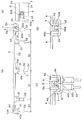
- FIG. 1 An example of the inner layer structure of the pipe of the present invention is shown, in which (a) is a cross-sectional view of the pipe, (b) is an enlarged view of the cross-section of the pipe, and (c) is an enlarged view of the vertical cross section of the pipe.
- connection structure of the adjacent connecting member is shown, (a) is an explanatory view in the longitudinal section direction of the pipe (fixing member omitted), (b) is an explanatory view in the transverse section direction of the pipe (inner surface material and inner surface material connecting material and connection) (Omitted), (c) and (d) are explanatory diagrams of the connecting piece. It is explanatory drawing which shows the construction procedure of the inner layer structure of the pipe
- FIG. 1 to FIG. 6 show an embodiment in which the existing pipe is repaired by applying the inner layer structure of the pipe of the present invention to an existing pipe such as an aged sewer pipe.
- the inner layer structure of this pipe includes a fixing member 2 installed at an interval in the tube axis direction of the existing pipe 1 along the inner peripheral surface of the existing pipe 1, and an inner surface material 4 disposed on the fixing member 2.
- the belt-like connecting member 3 provided with the first fitting portion 31 to be fitted and the second fitting portion 32 to be installed on the fixing member 2, and the first fitting portion 31 of the connecting member 3 It is composed of a band-shaped inner surface material 4 that is fitted and fixed to a fixing member 2 that is adjacent to the existing pipe 1 in the tube axis direction, and is configured by dividing the connecting member 3 so that each connecting member 3 is provided.
- the fixing member 2 is arranged through the second fitting portion 32.
- the inner layer structure of the pipe of the present invention is not limited to a pipe having a circular cross section as shown in the present embodiment, and can be applied to a pipe having an arbitrary shape such as a rectangle.
- the fixing member 2 has a shape along the inner peripheral surface of the existing pipe 1, preferably a substantially uniform interval with respect to the inner peripheral surface of the existing pipe 1 when installed along the inner peripheral surface of the existing pipe 1.
- a plurality of curved reinforcing bars preferably a bar-shaped member made of deformed reinforcing bars, etc.
- a steel material such as a shaped steel can be suitably used.
- the fixing member 2 is installed while being assembled in a closed loop shape in the circumferential direction of the existing pipe 1 using an arbitrary fixing member 21 such as an anchor. As a result, installation is easy and workability is good, and rebars and shaped steel are low cost materials because they are general-purpose materials.
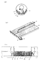
- the connecting member 3 is configured to be divided and arranged with respect to one fixing member 2.
- one or a plurality of (in this embodiment, both end portions and between them, A total of five) inner surface members 4 are fitted, and a first fitting portion 31 and a second fitting portion 32 for installation on the fixing member 2 are provided, and these are connected by a connecting piece 33 It is formed in a band shape.
- the longitudinal direction of the strip-shaped connecting member 3, the fitting direction of the first fitting part 31, and the fitting direction of the second fitting part 32 are respectively orthogonal to each other. .
- the first fitting portion 31 and the second fitting portion 31 are configured so that the fitting direction of the first fitting portion 31 and the fitting direction of the second fitting portion 32 are orthogonal to each other.
- the first fitting portion 31 and the second fitting portion 32 do not necessarily have to be provided correspondingly, but depending on the length of the strip-like connecting member 3 in the longitudinal direction and the like, both ends of the connecting member 3 It is preferable to provide a total of 3 or more and 7 or less (for example, per 30 cm width) in the vicinity of the part and other places.
- the gap between the connecting member 3 and the fixing member 2 or the inner surface material 4 becomes large in the vicinity of the central portion of the connecting member 3, which is not preferable.
- the second fitting part 32 provided in the intermediate part functions to prevent the fixing member 2 from rotating around the fixing member 2.
- the connecting member 3 includes a plurality of first fitting portions 31 and second fitting portions 32
- the first fitting portion 31 and the second fitting portion 32 are band-shaped connecting members. 3 are preferably provided at the same position in the longitudinal direction.
- the connecting member 3 is caused by the force.
- the inner surface material 4 can be securely fitted to the first fitting portion 31 of the connecting member 3 without bending.
- the material of the connecting member 3 is not particularly limited, and can be composed of a synthetic resin or a surface-treated metal, but a synthetic resin can be suitably used because of its weight, ease of manufacture, and the like.
- a synthetic resin having chemical resistance, abrasion resistance and alkali resistance is used.
- examples of such a synthetic resin include high density polyethylene, polypropylene, and polyvinyl chloride.
- synthetic resin such as high-density polyethylene, polypropylene, and vinyl chloride can be suitably used.
- the connecting member 3 can be manufactured by any known method. If the synthetic resin is a thermoplastic resin, it can be produced, for example, by injection molding, and if it is a metal, it can be produced, for example, by welding or casting.
- the first fitting portion 31 to which the inner surface material 4 is fitted has a shape that opens upward, and the three first fitting portions 31 in the middle portion prevent the inner surface material 4 from coming off.
- a locking claw 31a that engages with a locking claw 41a formed on the inner surface material 4 is formed in the opening so as to be fitted in a shape.
- the length (the dimension of a height direction) of the latching claw 31a and the latching claw 41a can be determined suitably, the diameter of the pipe after repair becomes too small with respect to the diameter of the existing pipe 1, and a flow-down capability It is preferable that the length is short so as not to decrease.
- the 1st fitting part 31 of both ends is connected via the inner surface material connection material 5 which does not form the latching claw 31a, but fits the end edges of the adjacent inner surface material 4 in a retaining shape. Like to do. For this reason, the position of the both ends of the circumferential direction of the existing pipe 1 of the connection member 3 and the inner surface material 4 is made to correspond. Thereby, positioning of the inner surface material 4 becomes easy and workability is improved. In this case, the circumferential length and width of the existing pipe 1 of the connecting member 3 and the inner surface material 4 are the same in order to make the positions of both ends in the circumferential direction of the existing pipe 1 of the connecting member 3 and the inner surface material 4 equal.
- the length of the connecting member 3 is an integral multiple of the width of the inner surface material 4, and a portion for fitting both end edges of the inner surface material 4 is provided at an appropriate position of the connecting member 3.
- the clearance between the connecting member 3 and the inner surface material 4 is preferably 1 to 10 mm. In the case of less than 1 mm, it is difficult to absorb the shift of the position of the first fitting portion 31 of the connecting member 3 and the fitted portion of the inner surface material 4 due to the dimensional error of the connecting member 3 and the inner surface material 4. Absent. On the other hand, if it exceeds 10 mm, the diameter of the pipe after repair becomes too small with respect to the diameter of the existing pipe 1, which is not preferable because the flow-down ability is lowered.
- the second fitting portion 32 to be installed on the fixing member 2 has a U-shape in which an opening 32a for fitting the fixing member 2 is formed in the lateral direction (the tube axis direction of the existing tube 1). And a stabilizer 34 that also serves as a reinforcing rib having a slightly smaller dimension than the inner peripheral surface of the existing pipe 1 along the outer side of the second fitting portion 32. .
- channel is provided with the length inserted in the two fixing members 2 arranged in parallel, as shown in FIG.2 (b). Accordingly, the second fitting portion 32 can be stably fitted to the fixing member 2 so as to hold the two fixing members 2 provided side by side at the connection portion.
- the stabilizer 34 it is possible to prevent the second fitting portion 32 installed on the fixing member 2 from rotating around the fixing member 2. And among the 2nd fitting parts 32, the 2nd fitting parts 32 of both ends, for example, are fixed so that fixing member 2 inserted in the inner surface may be held in the shape of a retaining. A protrusion 32b is formed for this purpose. Further, the second fitting portion 32 preferably has a dimension in the direction toward the central axis of the existing pipe 1 that is 1 to 15 mm larger than the dimension (diameter) of the fixing member 2. Thereby, when connecting member 3 and inner surface material 4 are arranged in the peripheral direction of existing pipe 1, it can adjust so that a gap by a dimensional error etc. of connecting member 3 and inner surface material 4 may not arise.
- the second fitting portion 32 for installation on the fixing member 2 is provided with the opening 32a in the lateral direction (the tube axis direction of the existing pipe 1). It can also be formed in a radial direction (in the direction of the inner peripheral surface of the existing pipe 1) or in a hole shape having no opening (the fixing member 2 is inserted through the hole).
- the second fitting portion 32 for installation on the fixing member 2 is provided with the opening 32a in the same direction in the lateral direction (the tube axis direction of the existing tube 1).
- the direction of the opening 32a of the two fitting portions 32 may be directed to a direction different by 180 ° across the reference point.
- the reference point is preferably set in the vicinity of the intermediate position in the longitudinal direction of the strip-shaped connecting member 3. Thereby, the 2nd fitting part 32 can be simply attached to the fixing member 2 one by one by rotating the connection member 3 centering on a reference point.
- the inner peripheral surface of the connecting piece 33 on which the first fitting portion 31 of the connecting member 3 is formed is formed to be flush. Thereby, it is possible to arrange the inner surface material 4 with high workability and high accuracy so as not to cause unevenness in the circumferential direction. Specifically, even when the first fitting portion 31 of the connecting member 3 is difficult to be seen by the inner surface material 4, the inner surface material 4 is moved on the connecting member 3 in the length direction of the connecting member 3, thereby The position of the first fitting portion 31 of the connecting member 3 corresponding to the locking claw 41a of the material 4 can be specified. Further, for example, as shown in the present embodiment, the first fitting portions 31 at both ends and the first fitting portions 31 are adjacent to each other so that the intervals at which the first fitting portions 31 are provided are different.
- the interval L1 between the first fitting portions 31 and the interval L2 between adjacent first fitting portions 31 other than both end portions are set to be different. Thereby, when the engaging claw 41a of the inner surface material 4 is fitted to the first fitting portion 31 of the connecting member 3 whose position does not correspond, the other engaging claw 41a of the inner surface material 4 and the first of the connecting member 3 are fitted. Since the misalignment occurs with the fitting portion 31 of the inner member 4 and the fitting cannot be performed, it is possible to prevent the inner member 4 from being erroneously attached, and the first connecting member 3 corresponding to the locking claw 41a of the inner member 4 can be prevented. The position of the fitting portion 31 can be accurately specified.
- the connecting member 3 can be disposed along the fixing member 2 so that the position thereof can be adjusted. Note that the position of the connecting member 3 can also be adjusted in the pipe axis direction of the existing pipe 1 via the second fitting portion 32. Thereby, the connecting member 3 can be disposed along the fixing member 2 with a degree of freedom.
- the connecting member 3 is divided and arranged with respect to the single fixing member 2, and includes a second fitting portion for arranging the connecting member 3 so that the position thereof can be adjusted along the fixing member 2.
- the connecting member 3 can be adjusted to the fixing member 2 assembled in a closed loop shape and can be accurately arranged along the fixing member 2, and the belt-shaped inner surface material 4 is attached to the existing pipe 1.
- the inner surface material 4 can be arranged with high accuracy so as not to cause irregularities in the tube axis direction of the existing pipe 1 in combination with the fixing member 2 which is adjacent in the tube axis direction.
- the length of the connecting member 3 (the length in the direction along the fixed member 2) is 60 mm to 2400 mm which is 1/2 or less of the entire circumference of the existing pipe 1 and is applied over the entire circumference of the existing pipe 1 In addition, it is preferable to set so that no gap occurs between the connecting members 3. If the length is less than 60 mm, the number is too short for construction over the entire circumference, resulting in poor workability. On the other hand, if it exceeds 2400 mm, it will become difficult to fit in the fixing member 2, and it will be inferior to workability.
- connection member 3 when the connection member 3 is divided and formed in the circumferential direction of the pipe, the end portions of the connection members 3 adjacent to each other in the circumferential direction of the pipe are connected to each other by a connection piece 35 as shown in FIG. It is preferable to connect them. Connection between the end portions of the connecting member 3 is performed by attaching a connection piece 35 as shown in FIG. 4C or 4D to a slit-like groove 34a formed in the stabilizer 34 provided on the back side of the opening 32a. In addition, it can be fixed and connected with bolts and nuts. Thereby, the integrity of the connecting member 3 connected via the connection piece 35 can be improved.
- connection piece 35 can be provided with a spacer function for adjusting the distance d (the dimension of the gap) between the ends of the connecting members 3 adjacent in the circumferential direction of the pipe. Therefore, the connecting piece 35 is provided with a clamping portion 35b and a contact portion 35c at both ends of a shaft portion 35a inserted into a slit-like groove 34a formed in the stabilizer 34 as shown in FIG.
- the connecting piece 35 is provided with a clamping portion 35b and a contact portion 35c at both ends of a shaft portion 35a inserted into a slit-like groove 34a formed in the stabilizer 34 as shown in FIG.
- the dimensional deviation between the connecting member 3 and the inner surface material 4 to be absorbed by the connecting piece 35 that is, the distance d between the ends of the connecting member 3 depends on the curvature (diameter) of the existing pipe 1,
- the existing pipe 1 having a diameter of 1000 mm is set to about 10 mm
- the existing pipe 1 having a diameter of 2000 mm is set to about 5 mm.
- the connection piece 35 was comprised with the connection member 3 and another member, it can also be made to form integrally in the one side of the connection member 3.
- the belt-shaped inner surface material 4 and the inner surface material connecting material 5 for connecting the inner surface material 4 are arranged so that the longitudinal direction is the tube axis direction of the existing tube 1.
- the material of the inner surface material 4 and the inner surface material connecting material 5 is not particularly limited, and can be composed of a synthetic resin or a surface-treated metal. It can be used suitably.
- a synthetic resin having chemical resistance, abrasion resistance and alkali resistance is used.
- Examples of such a synthetic resin include high density polyethylene, polypropylene, and polyvinyl chloride.
- the inner surface material 4 and the inner surface material connecting material 5 can be manufactured by any known method.
- the synthetic resin is a thermoplastic resin or aluminum and a long one is obtained, it can be produced by, for example, extrusion molding.
- the width of the inner surface material 4 (the length in the direction along the fixing member 2) is preferably 60 mm to 600 mm. If the width is less than 60 mm, the width is too narrow and the number is too large for construction over the entire circumference, resulting in poor workability. On the other hand, if it exceeds 600 mm, it may be difficult to carry in from a human hole, and the width is too wide and the workability in a narrow pipe is inferior.
- the length of the inner surface material 4 and the inner surface material connecting material 5 may be any length, but preferably has a length necessary for repair.
- the inner surface material 4 or the inner surface material connecting material 5 is joined in the longitudinal direction by welding, bonding, welding, etc., so that water leaks at the joint. It is preferable to make the structure free from any problem.
- a method for joining the inner surface material 4 and the inner surface material connecting material 5 a known method can be applied according to the material. For example, it can be joined by welding when it is made of a polyolefin resin such as polyethylene, by adhesion when it is made of polyvinyl chloride, or by welding when it is made of metal.
- the inner surface member 4 is provided with a first spring 40 a extending from the base side of the inner surface member 4 so as to close the concave connection space 40 formed at the circumferential end of the existing pipe 1. To do. Thereby, while the 1st splash 40a improves the waterproofing property of the connection space 40, it absorbs the play of the connection space 40, and also with respect to the force of the direction in which the connection state of the inner surface material 4 is cancelled
- the connection of the inner surface material 4 by the inner surface material connecting material 5 is performed by forming a locking claw 40b at the end of the inner surface material 4 as shown in FIGS.
- the engaging claws 40b of the adjacent inner surface materials 4 are held by the engaging claws 5b formed on the inner surface material connecting material 5.
- the water stop material 7 is arrange
- the connection space 40 is closed by the second spring, and the water stopping property is reduced. It can be improved further.
- the second spring 5a and the inner surface material are arranged. 4 and the locking claw 5b and the first splash 40a can be surely stopped, and the stability of the connection state of the inner surface material 4 by the inner surface material connecting material 5 is improved. To be able to.
- the 1st splash 40a and the water stop material 8 can also be abbreviate
- connection between the inner surface materials 4 is formed by forming a locking claw 42 a in the fitting portion 42 of the inner surface material 4 and forming the locking claw 42 a in the fitting portion 43 of the adjacent inner surface material 4. 43a is carried out so as to be held.
- the water stop material 7 is arrange
- a second spring 40c reaching the surface of the other inner surface material 4 adjacent to the fitting portion 43 of one inner surface material 4 from the base side of the inner surface material 4, the second The thread 40c closes the connection space 40 so that the water stoppage can be further improved.
- the fitting operation of the inner surface material 4 to the first fitting portion 31 of the connecting member 3 is performed after the connecting member 3 is disposed on the fixing member 2 as shown in FIG.
- the inner surface material 4 is sequentially joined in the longitudinal direction by welding, adhesion, welding or the like, and drawn into the existing pipe 1 from the human hole 11. .
- the inner layer structure of the pipe of the present invention and the connecting member used therefor simplify the installation work by eliminating the trouble of assembling the constituent members including the inner surface material, while allowing the inner surface material to be arranged with high accuracy, and Since it can provide a long-lasting pipe inner layer structure even after the completion of work, it can be suitably used for repairing existing pipes such as aged sewer pipes. It can also be used for finishing the inner surface.
Abstract
The purpose of the present invention is to provide a pipe inner-layer structure which exhibits long-term durability even after work completion, and which simplifies installation work by dispensing with labour related to the assembly of component members including an inner surface material, while enabling the inner surface material to be accurately disposed. Accordingly, the present invention comprises: fixed members (2) provided along an inner peripheral surface of a pre-installed pipe (1) with spaces therebetween in the pipe-axial direction of the pre-installed pipe (1); connection members (3) which are provided to the fixed members (2), and which are each provided with a first fitting member (31) having an inner surface material (4) fitted thereto, and a second fitting member (32) for attaching to the fixed members (2); and the band-like inner surface material (4) which is fitted to the first fitting members (31) of the connection members (3), and which is provided across adjacent fixed members (2) in the pipe-axial direction of the pre-installed pipe (1). The connection members (3) are divided, configured, and provided to the fixed members (2) via the second fitting members (32) with which each of the connection members (3) is provided.
Description
本発明は、管の内層構造及びそれに使用する連結部材に関し、特に、下水道管等の比較的大口径の既設管の補修に適した管の内層構造及びそれに使用する連結部材に関するものである。
The present invention relates to an inner layer structure of a pipe and a connecting member used therefor, and more particularly to an inner layer structure of a pipe suitable for repairing an existing pipe having a relatively large diameter such as a sewer pipe and a connecting member used therefor.
従来、老朽化した下水道管等の既設管の補修構造として、既設管の内面を内張り材で全面的に覆う既設管の補修構造が数多く提案されている(例えば、特許文献1及び2参照。)。
このうち、特許文献1に記載のものは、組み立てることにより管状、角形又は馬蹄形の筒状体を構成する、内周面を構成する内面板と、該内面板の周縁に立設された外周板とをプラスチックによって一体に形成した流路施設修復用ブロック体を用いて施工されるものであり、また、特許文献2に記載のものは、既設管路内に、当該既設管路内面に略沿った中空骨組み状補強材が配置され、その補強材の内側に、既設管路の筒長方向並びに周方向にそれぞれ複数の内面部材が連続的に取り付けられて筒状に組み立てられているとともに、既設管路の筒長方向に隣接している内面部材同士は、互いの端面が当接した状態で、双方の内面部材に跨って配置された内面材連接材により相互に連結されてなり、内面部材と既設管路内面との間に硬化性充填材が充填されてなるものである。 Conventionally, many repair structures for existing pipes that cover the entire inner surface of the existing pipe with a lining material have been proposed as repair structures for existing pipes such as sewer pipes (see, for example,Patent Documents 1 and 2). .
Among these, the thing ofpatent document 1 is comprising the inner surface board which comprises a tubular, square shape, or a horseshoe-shaped cylindrical body by assembling, and the outer peripheral board erected on the periphery of the inner face board Is constructed using a block body for repairing a flow path facility integrally formed of plastic, and the one described in Patent Document 2 is substantially along the inner surface of the existing pipe line in the existing pipe line. The hollow frame-shaped reinforcing material is disposed, and a plurality of inner surface members are continuously attached to the inside of the reinforcing material in the cylinder length direction and the circumferential direction of the existing pipe line, respectively. The inner surface members adjacent to each other in the tube length direction of the pipe line are connected to each other by the inner surface material connecting material arranged across both inner surface members in a state where the end surfaces of the inner surface members are in contact with each other. Between the existing pipe and the inner surface of the existing pipe Wood is made is filled.
このうち、特許文献1に記載のものは、組み立てることにより管状、角形又は馬蹄形の筒状体を構成する、内周面を構成する内面板と、該内面板の周縁に立設された外周板とをプラスチックによって一体に形成した流路施設修復用ブロック体を用いて施工されるものであり、また、特許文献2に記載のものは、既設管路内に、当該既設管路内面に略沿った中空骨組み状補強材が配置され、その補強材の内側に、既設管路の筒長方向並びに周方向にそれぞれ複数の内面部材が連続的に取り付けられて筒状に組み立てられているとともに、既設管路の筒長方向に隣接している内面部材同士は、互いの端面が当接した状態で、双方の内面部材に跨って配置された内面材連接材により相互に連結されてなり、内面部材と既設管路内面との間に硬化性充填材が充填されてなるものである。 Conventionally, many repair structures for existing pipes that cover the entire inner surface of the existing pipe with a lining material have been proposed as repair structures for existing pipes such as sewer pipes (see, for example,
Among these, the thing of
しかしながら、特許文献1に記載のものは、合成樹脂製のブロック体を使用するために高価な金型を必要とすることから、コストがかかり、また、数多くのブロック体の組み立てに多大な手間を要するものであり、また、特許文献2に記載のものは、既設管路の補修長が長くなるに従い、内面部材及び嵌合部材を筒長方向に連続したものを使用しようとする場合の輸送上又は製造設備上、製造現場における設置スペース等の問題を解決するものの、既設管路内に中空骨組み状の補強材を配置するのに補強材が多数の部材からなり補強材を既設管路内で組み立てるのに多大な手間を要し、また、内面部材の数も多くこれを同様に数の多い嵌合部材に係止するのに多大な手間を要するものとなっている。
However, since the thing of patent document 1 requires an expensive metal mold | die in order to use the block body made from a synthetic resin, it is expensive, and a lot of labor is required for the assembly of many block bodies. In addition, the one described in Patent Document 2 is used for transportation when the inner surface member and the fitting member are continuously used in the cylinder length direction as the repair length of the existing pipe line becomes longer. Or, although it solves problems such as installation space at the manufacturing site on the manufacturing facility, the reinforcing material is composed of a number of members to arrange the reinforcing material in the form of a hollow frame in the existing pipeline, It takes a lot of labor to assemble, and the number of inner surface members is also large, and it takes a lot of trouble to lock the same to a large number of fitting members.
一方、このような実情に鑑み、経済的な部材を用い、その組み立ての手間を省いて設置作業を簡便化し、かつ、作業完了後においても長期に亘って耐久性のある既設管の補修構造として、既設管の内周面の周方向に沿って、管軸方向に所定の間隔をあけて配設した剛性リングと、これら剛性リングの内側に跨るように管軸方向に、剛性リングの周方向に所定の間隔をあけて配設した既設管の中心側に所定の間隔をあけて形成した切欠きを有する剛性直材と、該剛性直材の切欠きに対応する突条を有する帯状の合成樹脂製内面材とからなり、前記合成樹脂製内面材の突条を剛性直材の切欠きに嵌着することにより、合成樹脂製内面材を既設管の内周面の周方向に沿って、かつ、管軸方向に隙間なく順次配設し、既設管と合成樹脂製内面材との間に生じる空隙に硬化性充填材を充填したものも提案されている(例えば、特許文献3参照。)が、合成樹脂製内面材が既設管の内周面の周方向に沿って配設されるものであるため、内面材を管軸方向に凹凸を生じないように精度高く配設することができず、既設管路の補修長が長くなるに従い、内面材の配設の手数がかかるという問題があった。
On the other hand, in view of such a situation, using an economical member, simplifying the installation work by omitting the assembly work, and as a repair structure for existing pipes that is durable for a long time after the work is completed A rigid ring disposed at a predetermined interval in the pipe axis direction along the circumferential direction of the inner peripheral surface of the existing pipe, and the circumferential direction of the rigid ring in the pipe axis direction so as to straddle the inside of the rigid ring A rigid straight member having a notch formed at a predetermined interval on the center side of an existing pipe disposed at a predetermined interval on the center, and a strip-shaped composite having a protrusion corresponding to the notch of the rigid direct member It consists of a resin inner surface material, and the synthetic resin inner surface material is fitted along the circumferential direction of the inner peripheral surface of the existing pipe by fitting the protrusion of the synthetic resin inner surface material into the notch of the rigid straight material, And it arranges sequentially without gap in the direction of the pipe axis, and the existing pipe and the inner surface material made of synthetic resin Although the thing which filled the space | gap which arises in this with the sclerosing | hardenable filler is proposed (for example, refer patent document 3), the synthetic resin inner surface material is arrange | positioned along the circumferential direction of the internal peripheral surface of the existing pipe | tube. Therefore, the inner surface material cannot be arranged with high accuracy so as not to cause unevenness in the pipe axis direction, and the trouble of arranging the inner surface material increases as the repair length of the existing pipe line becomes longer. was there.
本発明は、このような実情に鑑みてなされたもので、内面材を精度高く配設することを可能にしながら、内面材を含む、構成部材の組み立ての手間を省いて設置作業を簡便化し、かつ、作業完了後においても長期に亘って耐久性のある管の内層構造及びそれに使用する連結部材を提供することを目的とする。
The present invention has been made in view of such a situation, while simplifying the installation work by eliminating the trouble of assembling the constituent members including the inner surface material while enabling the inner surface material to be arranged with high accuracy. Another object of the present invention is to provide a pipe inner layer structure that is durable for a long period of time even after the completion of work and a connecting member used therefor.
上記目的を達成するため、本発明の管の内層構造は、管の内周面に沿って、管軸方向に間隔をあけて設置した固定部材と、該固定部材に配設した、内面材が嵌着される第1の嵌着部を備えた連結部材と、該連結部材の第1の嵌着部に嵌着して、管軸方向に隣接する固定部材に架設した帯状の内面材とからなる管の内層構造であって、前記連結部材を、前記固定部材に対して分割して配設するようにするとともに、該連結部材を固定部材に設置するための第2の嵌着部を備えたことを特徴とする。
In order to achieve the above-mentioned object, the inner layer structure of the pipe of the present invention comprises a fixing member installed at an interval in the pipe axis direction along the inner peripheral surface of the pipe, and an inner surface material disposed on the fixing member. From a connecting member having a first fitting portion to be fitted, and a band-shaped inner surface material that is fitted to the first fitting portion of the coupling member and is laid on a fixing member adjacent in the tube axis direction An inner layer structure of a pipe, wherein the connecting member is divided and disposed with respect to the fixing member, and includes a second fitting portion for installing the connecting member on the fixing member. It is characterized by that.
この場合において、前記第2の嵌着部によって、連結部材が固定部材に沿って位置調整可能に配設するようにすることができる。
In this case, the connecting member can be arranged along the fixing member so that the position thereof can be adjusted by the second fitting portion.
また、前記連結部材の第1の嵌着部を形成した面を面一に形成することができる。
Further, the surface on which the first fitting portion of the connecting member is formed can be formed flush with each other.
また、前記連結部材の各々に複数の第2の嵌着部を備えるようにすることができる。
Further, each of the connecting members can be provided with a plurality of second fitting portions.
また、本発明の管の内層構造に使用する連結部材は、管の内周面に沿って設置される固定部材と内面材とを接合するために用いられる連結部材であって、全体形状が帯状をなし、内面材が嵌着される第1の嵌着部と、固定部材に設置するための第2の嵌着部とを備えてなることを特徴とする。
Further, the connecting member used for the inner layer structure of the pipe of the present invention is a connecting member used for joining a fixing member and an inner surface material installed along the inner peripheral surface of the pipe, and the overall shape is a band shape. It comprises the 1st fitting part by which inner surface material is fitted, and the 2nd fitting part for installing in a fixed member, It is characterized by the above-mentioned.
この場合において、第1の嵌着部の嵌着方向及び第2の嵌着部の嵌着方向が、直交する方向になるようにすることができる。
In this case, the fitting direction of the first fitting part and the fitting direction of the second fitting part can be orthogonal to each other.
また、第2の嵌着部を、固定部材に嵌入するためのU字状の溝から構成することができる。
Further, the second fitting portion can be constituted by a U-shaped groove for fitting into the fixing member.
また、連結部材に複数個の第2の嵌着部を備え、それぞれの第2の嵌着部のU字状の溝の開口方向を、基準点を挟んで180°異なる方向を向くようにすることができる。
Further, the connecting member includes a plurality of second fitting portions, and the opening directions of the U-shaped grooves of the respective second fitting portions are directed to different directions by 180 ° across the reference point. be able to.
また、第2の嵌着部のU字状の溝を、並設された2本の固定部材に嵌入する長さを備えるようにすることができる。
Also, the U-shaped groove of the second fitting portion can be provided with a length that fits into the two fixing members provided side by side.
また、連結部材に複数個の第1の嵌着部及び第2の嵌着部を備え、該第1の嵌着部及び第2の嵌着部を帯状の連結部材の長手方向における同じ位置に設けるようにすることができる。
The connecting member includes a plurality of first fitting portions and second fitting portions, and the first fitting portion and the second fitting portion are arranged at the same position in the longitudinal direction of the belt-like connecting member. It can be provided.
また、連結部材が、接続片を介して、管の周方向に一体に接続されてなるようにすることができる。
Further, the connecting member can be integrally connected in the circumferential direction of the pipe via the connection piece.
また、接続片が、管の周方向に隣接する連結部材の端部間の距離を調整するスペーサ機能を備えるようにすることができる。
Further, the connecting piece can be provided with a spacer function for adjusting the distance between the ends of the connecting members adjacent in the circumferential direction of the pipe.
本発明の管の内層構造及びそれに使用する連結部材によれば、連結部材を、前記固定部材に対して分割して配設するようにするとともに、該連結部材を固定部材に設置するための第2の嵌着部を備えるようにすることにより、管の内周面に沿って配置した固定部材に沿って正確に連結部材を配設することができ、帯状の内面材を管軸方向に隣接する固定部材に架設するようにしたことと相俟って、内面材を管軸方向に凹凸を生じないように精度高く配設することができる。
そして、内面材を含む、構成部材の組み立ての手間を省いて設置作業を簡便化し、かつ、作業完了後においても長期に亘って耐久性のある管の内層構造を提供することができる。 According to the inner layer structure of the pipe of the present invention and the connecting member used therefor, the connecting member is divided and arranged with respect to the fixing member, and the connecting member is installed on the fixing member. By providing the two fitting portions, the connecting member can be accurately disposed along the fixing member disposed along the inner peripheral surface of the tube, and the strip-shaped inner surface material is adjacent to the tube axis direction. In combination with the construction of the fixing member, the inner surface material can be arranged with high accuracy so as not to cause unevenness in the tube axis direction.
In addition, it is possible to simplify the installation work by omitting the work of assembling the constituent members including the inner surface material, and to provide a durable inner layer structure of the pipe for a long time even after the work is completed.
また、前記第2の嵌着部によって、連結部材が固定部材に沿って位置調整可能に配設するようにすることにより、連結部材を固定部材に沿って自由度を持って配設することができる。
Further, the connecting member can be arranged along the fixing member with a degree of freedom by arranging the connecting member so that the position of the connecting member can be adjusted along the fixing member by the second fitting portion. it can.
また、前記連結部材の第1の嵌着部を形成した面を面一に形成するようにすることにより、内面材を作業性よく、かつ、周方向に凹凸を生じないように精度高く配設することができる。
In addition, by forming the surface on which the first fitting portion of the connecting member is formed to be flush with each other, the inner surface material is arranged with high workability and high accuracy so as not to cause unevenness in the circumferential direction. can do.
また、前記連結部材の各々に複数の第2の嵌着部を備えるようにすることにより、連結部材を固定部材に沿ってより正確に配設することができる。
Further, by providing each of the connecting members with a plurality of second fitting portions, the connecting members can be more accurately arranged along the fixing member.
また、第1の嵌着部の嵌着方向及び第2の嵌着部の嵌着方向が、直交する方向になるようにすることにより、第1の嵌着部及び第2の嵌着部のそれぞれの嵌着状態を安定して維持することができる。
Moreover, by making the fitting direction of the first fitting part and the fitting direction of the second fitting part orthogonal to each other, the first fitting part and the second fitting part Each fitting state can be maintained stably.
また、第2の嵌着部を、固定部材に嵌入するためのU字状の溝から構成することにより、第2の嵌着部を固定部材に簡易に嵌入することができるとともに、嵌着状態を安定して維持することができる。
In addition, by configuring the second fitting portion from a U-shaped groove for fitting into the fixing member, the second fitting portion can be easily fitted into the fixing member, and the fitting state Can be maintained stably.
また、連結部材に複数個の第2の嵌着部を備え、それぞれの第2の嵌着部のU字状の溝の開口方向を、基準点を挟んで180°異なる方向を向くようにすることにより、基準点を回転中心として連結部材を回転させることによって、第2の嵌着部を固定部材に簡易に嵌着させることができる。
Further, the connecting member includes a plurality of second fitting portions, and the opening directions of the U-shaped grooves of the respective second fitting portions are directed to different directions by 180 ° across the reference point. Thus, the second fitting portion can be easily fitted to the fixing member by rotating the connecting member around the reference point as the rotation center.
また、第2の嵌着部のU字状の溝を、並設された2本の固定部材に嵌入する長さを備えるようにすることにより、第2の嵌着部を、接続部分において2本が並設される固定部材に安定して嵌着させることができる。
In addition, the U-shaped groove of the second fitting portion is provided with a length that fits into the two fixing members arranged in parallel, so that the second fitting portion is connected to the connection portion at 2. The book can be stably fitted to the fixing member arranged side by side.
また、連結部材に複数個の第1の嵌着部及び第2の嵌着部を備え、該第1の嵌着部及び第2の嵌着部を帯状の連結部材の長手方向における同じ位置に設けるようにすることにより、内面材を嵌着させる際に第1の嵌着部にかかる力が、第2の嵌着部を介して固定部材によって支持されるため、当該力によって連結部材が撓むことがなく、内面材を連結部材の第1の嵌着部に確実に嵌着させることができる。
The connecting member includes a plurality of first fitting portions and second fitting portions, and the first fitting portion and the second fitting portion are arranged at the same position in the longitudinal direction of the belt-like connecting member. Since the force applied to the first fitting portion is supported by the fixing member through the second fitting portion when the inner surface material is fitted, the connecting member is bent by the force. Therefore, the inner surface material can be securely fitted to the first fitting portion of the connecting member.
また、連結部材が、接続片を介して、管の周方向に一体に接続されてなるようにすることにより、連結部材の一体性を向上することができる。
Moreover, the integrity of the coupling member can be improved by connecting the coupling member integrally in the circumferential direction of the pipe via the connection piece.
また、接続片が、管の周方向に隣接する連結部材の端部間の距離を調整するスペーサ機能を備えるようにすることにより、連結部材及び内面材を敷設する管の曲率の違いによる連結部材と内面材との寸法のずれを、スペーサ機能を備えた接続片によって吸収することができ、内面材を連結部材の第1の嵌着部に確実に嵌着させることができる。
In addition, the connecting member is provided with a spacer function for adjusting the distance between the ends of the connecting members adjacent to each other in the circumferential direction of the pipe, so that the connecting member due to the difference in the curvature of the pipe laying the connecting member and the inner surface material. The displacement of the dimension between the inner member and the inner surface material can be absorbed by the connecting piece having the spacer function, and the inner surface material can be securely fitted to the first fitting portion of the connecting member.
以下、本発明の管の内層構造及びそれに使用する連結部材の実施の形態を、図面に基づいて説明する。
Hereinafter, embodiments of the inner layer structure of a pipe of the present invention and a connecting member used for the same will be described with reference to the drawings.
図1~図6に、本発明の管の内層構造を、老朽化した下水道管等の既設管に適用することにより、当該既設管を補修するようにした一実施例を示す。
この管の内層構造は、既設管1の内周面に沿って、既設管1の管軸方向に間隔をあけて設置した固定部材2と、この固定部材2に配設した、内面材4が嵌着される第1の嵌着部31及び固定部材2に設置するための第2の嵌着部32を備えた帯状の連結部材3と、この連結部材3の第1の嵌着部31に嵌着して、既設管1の管軸方向に隣接する固定部材2に架設した帯状の内面材4とからなり、連結部材3を分割して構成して、各々の連結部材3に備えるようにした第2の嵌着部32を介して固定部材2に配設するようにしている。 FIG. 1 to FIG. 6 show an embodiment in which the existing pipe is repaired by applying the inner layer structure of the pipe of the present invention to an existing pipe such as an aged sewer pipe.
The inner layer structure of this pipe includes afixing member 2 installed at an interval in the tube axis direction of the existing pipe 1 along the inner peripheral surface of the existing pipe 1, and an inner surface material 4 disposed on the fixing member 2. The belt-like connecting member 3 provided with the first fitting portion 31 to be fitted and the second fitting portion 32 to be installed on the fixing member 2, and the first fitting portion 31 of the connecting member 3 It is composed of a band-shaped inner surface material 4 that is fitted and fixed to a fixing member 2 that is adjacent to the existing pipe 1 in the tube axis direction, and is configured by dividing the connecting member 3 so that each connecting member 3 is provided. The fixing member 2 is arranged through the second fitting portion 32.
この管の内層構造は、既設管1の内周面に沿って、既設管1の管軸方向に間隔をあけて設置した固定部材2と、この固定部材2に配設した、内面材4が嵌着される第1の嵌着部31及び固定部材2に設置するための第2の嵌着部32を備えた帯状の連結部材3と、この連結部材3の第1の嵌着部31に嵌着して、既設管1の管軸方向に隣接する固定部材2に架設した帯状の内面材4とからなり、連結部材3を分割して構成して、各々の連結部材3に備えるようにした第2の嵌着部32を介して固定部材2に配設するようにしている。 FIG. 1 to FIG. 6 show an embodiment in which the existing pipe is repaired by applying the inner layer structure of the pipe of the present invention to an existing pipe such as an aged sewer pipe.
The inner layer structure of this pipe includes a
この場合において、本発明の管の内層構造は、本実施例に示すような、断面が円形の管に限定されず、矩形等の任意の形状の管にも適用することができる。
In this case, the inner layer structure of the pipe of the present invention is not limited to a pipe having a circular cross section as shown in the present embodiment, and can be applied to a pipe having an arbitrary shape such as a rectangle.
固定部材2は、既設管1の内周面に沿う形状、好ましくは、既設管1の内周面に沿って設置したときに、既設管1の内周面に対してほぼ均一な間隔を有して設置されるように、湾曲形成した複数の鉄筋、好ましくは、異形鉄筋等からなる棒状部材のほか、形鋼等の鋼材を好適に用いることができ、図5(a)に示すように、この固定部材2をアンカー等の任意の定着部材21を用いて既設管1の周方向に、閉ループ状に組み立てながら設置するようにする。
これにより、設置が容易で、作業性がよく、また、鉄筋や形鋼は、汎用材料のため、材料費が低廉である。 The fixingmember 2 has a shape along the inner peripheral surface of the existing pipe 1, preferably a substantially uniform interval with respect to the inner peripheral surface of the existing pipe 1 when installed along the inner peripheral surface of the existing pipe 1. As shown in FIG. 5 (a), a plurality of curved reinforcing bars, preferably a bar-shaped member made of deformed reinforcing bars, etc., and a steel material such as a shaped steel can be suitably used. The fixing member 2 is installed while being assembled in a closed loop shape in the circumferential direction of the existing pipe 1 using an arbitrary fixing member 21 such as an anchor.
As a result, installation is easy and workability is good, and rebars and shaped steel are low cost materials because they are general-purpose materials.
これにより、設置が容易で、作業性がよく、また、鉄筋や形鋼は、汎用材料のため、材料費が低廉である。 The fixing
As a result, installation is easy and workability is good, and rebars and shaped steel are low cost materials because they are general-purpose materials.
連結部材3は、図2に示すように、1つの固定部材2に対して分割して配設するように構成してなり、1又は複数個(本実施例においては、両端部と、その間に3個の合計5個)の内面材4が嵌着される第1の嵌着部31及び固定部材2に設置するための第2の嵌着部32を備え、これらを連結片33で接続した帯状をした形状に形成するようにしている。
この場合、帯状の連結部材3の長手方向、第1の嵌着部31の嵌着方向及び第2の嵌着部32の嵌着方向が、それぞれ直交する方向になるように構成することが好ましい。
これにより、第1の嵌着部31の嵌着方向及び第2の嵌着部32の嵌着方向を、直交する方向になるように構成することによって、第1の嵌着部31及び第2の嵌着部32のそれぞれの嵌着状態を安定して維持することができることに加え、複数の連結部材3の連結状態を安定して維持することができる。
第1の嵌着部31と、第2の嵌着部32とは、必ずしも対応して備える必要はないが、帯状の連結部材3の長手方向の長さ等に応じて、連結部材3の両端部付近とそれ以外の場所に、合計3個以上、7個以下(例えば、30cm幅当たり)の個数を備えることが好ましい。
両端部付近のみ(2個)の場合は、連結部材3に中央部付近で、連結部材3と固定部材2や内面材4との隙間が大きくなるので好ましくない。ここで、中間部に備えた第2の嵌着部32は、固定部材2が固定部材2の周りに回転することを防止する機能を果たしている。
一方、8個以上あると連結部材3と固定部材2や内面材4との隙間は小さくなるが、施工性が劣り、材料も多く必要になるので好ましくない。
また、連結部材3に複数個の第1の嵌着部31及び第2の嵌着部32を備える場合には、第1の嵌着部31及び第2の嵌着部32を帯状の連結部材3の長手方向における同じ位置に設けるようにすることが好ましい。
これにより、内面材4を嵌着させる際に第1の嵌着部31にかかる力が、第2の嵌着部32を介して固定部材2によって支持されるため、当該力によって連結部材3が撓むことがなく、内面材4を連結部材3の第1の嵌着部31に確実に嵌着させることができる。 As shown in FIG. 2, the connectingmember 3 is configured to be divided and arranged with respect to one fixing member 2. In the present embodiment, one or a plurality of (in this embodiment, both end portions and between them, A total of five) inner surface members 4 are fitted, and a first fitting portion 31 and a second fitting portion 32 for installation on the fixing member 2 are provided, and these are connected by a connecting piece 33 It is formed in a band shape.
In this case, it is preferable that the longitudinal direction of the strip-shaped connectingmember 3, the fitting direction of the first fitting part 31, and the fitting direction of the second fitting part 32 are respectively orthogonal to each other. .
Accordingly, the firstfitting portion 31 and the second fitting portion 31 are configured so that the fitting direction of the first fitting portion 31 and the fitting direction of the second fitting portion 32 are orthogonal to each other. In addition to being able to stably maintain the respective fitted states of the fitting portions 32, it is possible to stably maintain the connected state of the plurality of connecting members 3.
The firstfitting portion 31 and the second fitting portion 32 do not necessarily have to be provided correspondingly, but depending on the length of the strip-like connecting member 3 in the longitudinal direction and the like, both ends of the connecting member 3 It is preferable to provide a total of 3 or more and 7 or less (for example, per 30 cm width) in the vicinity of the part and other places.
In the case of only the vicinity of both ends (two pieces), the gap between the connectingmember 3 and the fixing member 2 or the inner surface material 4 becomes large in the vicinity of the central portion of the connecting member 3, which is not preferable. Here, the second fitting part 32 provided in the intermediate part functions to prevent the fixing member 2 from rotating around the fixing member 2.
On the other hand, if there are eight or more, the gap between the connectingmember 3 and the fixing member 2 or the inner surface material 4 becomes small, but this is not preferable because the workability is inferior and more material is required.
In addition, when the connectingmember 3 includes a plurality of first fitting portions 31 and second fitting portions 32, the first fitting portion 31 and the second fitting portion 32 are band-shaped connecting members. 3 are preferably provided at the same position in the longitudinal direction.
Thereby, since the force applied to the firstfitting portion 31 when the inner surface material 4 is fitted is supported by the fixing member 2 via the second fitting portion 32, the connecting member 3 is caused by the force. The inner surface material 4 can be securely fitted to the first fitting portion 31 of the connecting member 3 without bending.
この場合、帯状の連結部材3の長手方向、第1の嵌着部31の嵌着方向及び第2の嵌着部32の嵌着方向が、それぞれ直交する方向になるように構成することが好ましい。
これにより、第1の嵌着部31の嵌着方向及び第2の嵌着部32の嵌着方向を、直交する方向になるように構成することによって、第1の嵌着部31及び第2の嵌着部32のそれぞれの嵌着状態を安定して維持することができることに加え、複数の連結部材3の連結状態を安定して維持することができる。
第1の嵌着部31と、第2の嵌着部32とは、必ずしも対応して備える必要はないが、帯状の連結部材3の長手方向の長さ等に応じて、連結部材3の両端部付近とそれ以外の場所に、合計3個以上、7個以下(例えば、30cm幅当たり)の個数を備えることが好ましい。
両端部付近のみ(2個)の場合は、連結部材3に中央部付近で、連結部材3と固定部材2や内面材4との隙間が大きくなるので好ましくない。ここで、中間部に備えた第2の嵌着部32は、固定部材2が固定部材2の周りに回転することを防止する機能を果たしている。
一方、8個以上あると連結部材3と固定部材2や内面材4との隙間は小さくなるが、施工性が劣り、材料も多く必要になるので好ましくない。
また、連結部材3に複数個の第1の嵌着部31及び第2の嵌着部32を備える場合には、第1の嵌着部31及び第2の嵌着部32を帯状の連結部材3の長手方向における同じ位置に設けるようにすることが好ましい。
これにより、内面材4を嵌着させる際に第1の嵌着部31にかかる力が、第2の嵌着部32を介して固定部材2によって支持されるため、当該力によって連結部材3が撓むことがなく、内面材4を連結部材3の第1の嵌着部31に確実に嵌着させることができる。 As shown in FIG. 2, the connecting
In this case, it is preferable that the longitudinal direction of the strip-shaped connecting
Accordingly, the first
The first
In the case of only the vicinity of both ends (two pieces), the gap between the connecting
On the other hand, if there are eight or more, the gap between the connecting
In addition, when the connecting
Thereby, since the force applied to the first
連結部材3の材質は、特に限定されるものではなく、合成樹脂や表面処理した金属から構成することができるが、重量や製造のし易さ等から合成樹脂を好適に用いることができる。特に下水管を補修する際には、耐薬品性、耐摩耗性及び耐アルカリ性を有する合成樹脂を用いるようにする。そのような合成樹脂としては、高密度ポリエチレン、ポリプロピレン、ポリ塩化ビニル等が挙げられる。なお、下水管以外の補修においても、高密度ポリエチレン、ポリプロピレン、塩化ビニル等の合成樹脂製のものを好適に用いることができる。
連結部材3は、公知の任意の方法で製造することができる。合成樹脂が熱可塑性樹脂ならば、例えば、射出成形により製造することができ、金属ならば、例えば、溶接や鋳造により製造することができる。 The material of the connectingmember 3 is not particularly limited, and can be composed of a synthetic resin or a surface-treated metal, but a synthetic resin can be suitably used because of its weight, ease of manufacture, and the like. In particular, when repairing a sewer pipe, a synthetic resin having chemical resistance, abrasion resistance and alkali resistance is used. Examples of such a synthetic resin include high density polyethylene, polypropylene, and polyvinyl chloride. In addition, in repairs other than the sewer pipe, those made of synthetic resin such as high-density polyethylene, polypropylene, and vinyl chloride can be suitably used.
The connectingmember 3 can be manufactured by any known method. If the synthetic resin is a thermoplastic resin, it can be produced, for example, by injection molding, and if it is a metal, it can be produced, for example, by welding or casting.
連結部材3は、公知の任意の方法で製造することができる。合成樹脂が熱可塑性樹脂ならば、例えば、射出成形により製造することができ、金属ならば、例えば、溶接や鋳造により製造することができる。 The material of the connecting
The connecting
このうち、内面材4が嵌着される第1の嵌着部31は、上向きに開口した形状をするとともに、中間部の3個の第1の嵌着部31は、内面材4が抜け止め状に嵌着されるように、開口部に内面材4に形成した係止爪41aと係合する係止爪31aを形成するようにしている。
なお、係止爪31a及び係止爪41aの長さ(高さ方向の寸法)は適宜決めることができるが、既設管1の径に対して補修後の管の径が小さくなりすぎて流下能力が低下しないように長さが短いほうが好ましい。
また、両端部の第1の嵌着部31は、係止爪31aを形成せずに、隣接する内面材4の端縁同士を抜け止め状に嵌着する内面材連接材5を介して連結するようにしている。
このため、連結部材3と内面材4の既設管1の周方向の両端部の位置を一致させるようにしている。
これにより、内面材4の位置決めが容易になり、施工性が向上する。
この場合、連結部材3と内面材4の既設管1の周方向の両端部の位置を一致させるために、連結部材3と内面材4の既設管1の周方向の長さ及び幅を同じにするほか、連結部材3の長さが内面材4の幅の整数倍であり連結部材3の適切な位置に内面材4の両端縁を嵌着する部位を設けるようにしたり、内面材4の幅が連結部材3の長さの整数倍となるようにすることもできる。
また、連結部材3と内面材4との隙間は、1~10mmが好ましい。
1mm未満の場合には、連結部材3及び内面材4の寸法誤差により、連結部材3の第1の嵌着部31と内面材4の被嵌着部の位置のずれを吸収し難くなるため好ましくない。一方、10mmを超えると、既設管1の径に対して補修後の管の径が小さくなりすぎ、流下能力が低下するので好ましくない。 Among these, the firstfitting portion 31 to which the inner surface material 4 is fitted has a shape that opens upward, and the three first fitting portions 31 in the middle portion prevent the inner surface material 4 from coming off. A locking claw 31a that engages with a locking claw 41a formed on the inner surface material 4 is formed in the opening so as to be fitted in a shape.
In addition, although the length (the dimension of a height direction) of the latchingclaw 31a and the latching claw 41a can be determined suitably, the diameter of the pipe after repair becomes too small with respect to the diameter of the existing pipe 1, and a flow-down capability It is preferable that the length is short so as not to decrease.
Moreover, the1st fitting part 31 of both ends is connected via the inner surface material connection material 5 which does not form the latching claw 31a, but fits the end edges of the adjacent inner surface material 4 in a retaining shape. Like to do.
For this reason, the position of the both ends of the circumferential direction of the existingpipe 1 of the connection member 3 and the inner surface material 4 is made to correspond.
Thereby, positioning of theinner surface material 4 becomes easy and workability is improved.
In this case, the circumferential length and width of the existingpipe 1 of the connecting member 3 and the inner surface material 4 are the same in order to make the positions of both ends in the circumferential direction of the existing pipe 1 of the connecting member 3 and the inner surface material 4 equal. In addition, the length of the connecting member 3 is an integral multiple of the width of the inner surface material 4, and a portion for fitting both end edges of the inner surface material 4 is provided at an appropriate position of the connecting member 3. Can be an integral multiple of the length of the connecting member 3.
The clearance between the connectingmember 3 and the inner surface material 4 is preferably 1 to 10 mm.
In the case of less than 1 mm, it is difficult to absorb the shift of the position of the firstfitting portion 31 of the connecting member 3 and the fitted portion of the inner surface material 4 due to the dimensional error of the connecting member 3 and the inner surface material 4. Absent. On the other hand, if it exceeds 10 mm, the diameter of the pipe after repair becomes too small with respect to the diameter of the existing pipe 1, which is not preferable because the flow-down ability is lowered.
なお、係止爪31a及び係止爪41aの長さ(高さ方向の寸法)は適宜決めることができるが、既設管1の径に対して補修後の管の径が小さくなりすぎて流下能力が低下しないように長さが短いほうが好ましい。
また、両端部の第1の嵌着部31は、係止爪31aを形成せずに、隣接する内面材4の端縁同士を抜け止め状に嵌着する内面材連接材5を介して連結するようにしている。
このため、連結部材3と内面材4の既設管1の周方向の両端部の位置を一致させるようにしている。
これにより、内面材4の位置決めが容易になり、施工性が向上する。
この場合、連結部材3と内面材4の既設管1の周方向の両端部の位置を一致させるために、連結部材3と内面材4の既設管1の周方向の長さ及び幅を同じにするほか、連結部材3の長さが内面材4の幅の整数倍であり連結部材3の適切な位置に内面材4の両端縁を嵌着する部位を設けるようにしたり、内面材4の幅が連結部材3の長さの整数倍となるようにすることもできる。
また、連結部材3と内面材4との隙間は、1~10mmが好ましい。
1mm未満の場合には、連結部材3及び内面材4の寸法誤差により、連結部材3の第1の嵌着部31と内面材4の被嵌着部の位置のずれを吸収し難くなるため好ましくない。一方、10mmを超えると、既設管1の径に対して補修後の管の径が小さくなりすぎ、流下能力が低下するので好ましくない。 Among these, the first
In addition, although the length (the dimension of a height direction) of the latching
Moreover, the
For this reason, the position of the both ends of the circumferential direction of the existing
Thereby, positioning of the
In this case, the circumferential length and width of the existing
The clearance between the connecting
In the case of less than 1 mm, it is difficult to absorb the shift of the position of the first
また、固定部材2に設置するための第2の嵌着部32は、固定部材2を嵌入するようにするための開口32aを横方向(既設管1の管軸方向)に形成したU字状の溝で構成するとともに、第2の嵌着部32の外側に沿って既設管1の内周面に当接するか、それより若干小さい寸法の補強リブを兼ねたスタビライザ34を設けるようにしている。
U字状の溝で構成した第2の嵌着部32は、図2(b)に示すように、並設された2本の固定部材2に嵌入する長さを備えるようにする。
これにより、第2の嵌着部32を、接続部分において2本が並設される固定部材2を抱持するようにして、固定部材2に安定して嵌着させることができる。
また、スタビライザ34を設けることにより、固定部材2に設置した第2の嵌着部32が、固定部材2の周りに回転することを防止することができる。
そして、第2の嵌着部32のうち、例えば、両端部の第2の嵌着部32は、必要に応じて、その内面に嵌入された固定部材2が抜け止め状に保持されるようにするための突起32bを形成するようにしている。
また、第2の嵌着部32は、既設管1の中心軸に向かう方向の寸法が、固定部材2の寸法(径)よりも、1~15mm大きいことが好ましい。
これにより、連結部材3や内面材4を既設管1の周方向に並べた際に、連結部材3や内面材4の寸法誤差等による隙間が生じないように調整することができる。
なお、本実施例において、固定部材2に設置するための第2の嵌着部32は、横方向(既設管1の管軸方向)に開口32aを備えたものとしたが、開口の方向を放射方向(既設管1の内周面方向)としたり、開口を有しない孔形状(当該孔に固定部材2を挿通するようにする。)に形成することもできる。
また、本実施例において、固定部材2に設置するための第2の嵌着部32は、横方向(既設管1の管軸方向)の同じ方向に開口32aを備えたものとしたが、第2の嵌着部32の開口32aの方向を、基準点を挟んで180°異なる方向を向くようにすることもできる。
ここで、基準点は、帯状の連結部材3の長手方向の中間位置近傍に設定することが好ましい。
これにより、基準点を回転中心として連結部材3を回転させることによって、第2の嵌着部32を固定部材2に順次簡易に嵌着させることができる。 Further, the secondfitting portion 32 to be installed on the fixing member 2 has a U-shape in which an opening 32a for fitting the fixing member 2 is formed in the lateral direction (the tube axis direction of the existing tube 1). And a stabilizer 34 that also serves as a reinforcing rib having a slightly smaller dimension than the inner peripheral surface of the existing pipe 1 along the outer side of the second fitting portion 32. .
The 2ndfitting part 32 comprised by the U-shaped groove | channel is provided with the length inserted in the two fixing members 2 arranged in parallel, as shown in FIG.2 (b).
Accordingly, the secondfitting portion 32 can be stably fitted to the fixing member 2 so as to hold the two fixing members 2 provided side by side at the connection portion.
Further, by providing thestabilizer 34, it is possible to prevent the second fitting portion 32 installed on the fixing member 2 from rotating around the fixing member 2.
And among the 2ndfitting parts 32, the 2nd fitting parts 32 of both ends, for example, are fixed so that fixing member 2 inserted in the inner surface may be held in the shape of a retaining. A protrusion 32b is formed for this purpose.
Further, the secondfitting portion 32 preferably has a dimension in the direction toward the central axis of the existing pipe 1 that is 1 to 15 mm larger than the dimension (diameter) of the fixing member 2.
Thereby, when connectingmember 3 and inner surface material 4 are arranged in the peripheral direction of existing pipe 1, it can adjust so that a gap by a dimensional error etc. of connecting member 3 and inner surface material 4 may not arise.
In the present embodiment, the secondfitting portion 32 for installation on the fixing member 2 is provided with the opening 32a in the lateral direction (the tube axis direction of the existing pipe 1). It can also be formed in a radial direction (in the direction of the inner peripheral surface of the existing pipe 1) or in a hole shape having no opening (the fixing member 2 is inserted through the hole).
In the present embodiment, the secondfitting portion 32 for installation on the fixing member 2 is provided with the opening 32a in the same direction in the lateral direction (the tube axis direction of the existing tube 1). The direction of the opening 32a of the two fitting portions 32 may be directed to a direction different by 180 ° across the reference point.
Here, the reference point is preferably set in the vicinity of the intermediate position in the longitudinal direction of the strip-shaped connectingmember 3.
Thereby, the 2ndfitting part 32 can be simply attached to the fixing member 2 one by one by rotating the connection member 3 centering on a reference point.
U字状の溝で構成した第2の嵌着部32は、図2(b)に示すように、並設された2本の固定部材2に嵌入する長さを備えるようにする。
これにより、第2の嵌着部32を、接続部分において2本が並設される固定部材2を抱持するようにして、固定部材2に安定して嵌着させることができる。
また、スタビライザ34を設けることにより、固定部材2に設置した第2の嵌着部32が、固定部材2の周りに回転することを防止することができる。
そして、第2の嵌着部32のうち、例えば、両端部の第2の嵌着部32は、必要に応じて、その内面に嵌入された固定部材2が抜け止め状に保持されるようにするための突起32bを形成するようにしている。
また、第2の嵌着部32は、既設管1の中心軸に向かう方向の寸法が、固定部材2の寸法(径)よりも、1~15mm大きいことが好ましい。
これにより、連結部材3や内面材4を既設管1の周方向に並べた際に、連結部材3や内面材4の寸法誤差等による隙間が生じないように調整することができる。
なお、本実施例において、固定部材2に設置するための第2の嵌着部32は、横方向(既設管1の管軸方向)に開口32aを備えたものとしたが、開口の方向を放射方向(既設管1の内周面方向)としたり、開口を有しない孔形状(当該孔に固定部材2を挿通するようにする。)に形成することもできる。
また、本実施例において、固定部材2に設置するための第2の嵌着部32は、横方向(既設管1の管軸方向)の同じ方向に開口32aを備えたものとしたが、第2の嵌着部32の開口32aの方向を、基準点を挟んで180°異なる方向を向くようにすることもできる。
ここで、基準点は、帯状の連結部材3の長手方向の中間位置近傍に設定することが好ましい。
これにより、基準点を回転中心として連結部材3を回転させることによって、第2の嵌着部32を固定部材2に順次簡易に嵌着させることができる。 Further, the second
The 2nd
Accordingly, the second
Further, by providing the
And among the 2nd
Further, the second
Thereby, when connecting
In the present embodiment, the second
In the present embodiment, the second
Here, the reference point is preferably set in the vicinity of the intermediate position in the longitudinal direction of the strip-shaped connecting
Thereby, the 2nd
連結部材3の第1の嵌着部31を形成した連結片33の内周側の面は、面一に形成するようにする。
これにより、内面材4を作業性よく、かつ、周方向に凹凸を生じないように精度高く配設することができる。具体的には、内面材4により連結部材3の第1の嵌着部31が見え難い状態においても、内面材4を連結部材3上を連結部材3の長さ方向に移動させることで、内面材4の係止爪41aに対応する連結部材3の第1の嵌着部31の位置を特定することができる。
また、第1の嵌着部31を設ける間隔が異なるように、例えば、本実施例に示すように、両端部の第1の嵌着部31と、この第1の嵌着部31と隣り合う第1の嵌着部31との間隔L1と、両端部以外の隣り合う第1の嵌着部31同士の間隔L2とが、異なるように設定することが好ましい。
これにより、内面材4の係止爪41aを位置が対応しない連結部材3の第1の嵌着部31に嵌着した場合、内面材4の他の係止爪41aと連結部材3の第1の嵌着部31とに位置ずれが生じて嵌着できなくなるため、内面材4の誤装着を未然に防止することができ、内面材4の係止爪41aに対応する連結部材3の第1の嵌着部31の位置を正確に特定することができる。 The inner peripheral surface of the connectingpiece 33 on which the first fitting portion 31 of the connecting member 3 is formed is formed to be flush.
Thereby, it is possible to arrange theinner surface material 4 with high workability and high accuracy so as not to cause unevenness in the circumferential direction. Specifically, even when the first fitting portion 31 of the connecting member 3 is difficult to be seen by the inner surface material 4, the inner surface material 4 is moved on the connecting member 3 in the length direction of the connecting member 3, thereby The position of the first fitting portion 31 of the connecting member 3 corresponding to the locking claw 41a of the material 4 can be specified.
Further, for example, as shown in the present embodiment, the firstfitting portions 31 at both ends and the first fitting portions 31 are adjacent to each other so that the intervals at which the first fitting portions 31 are provided are different. It is preferable that the interval L1 between the first fitting portions 31 and the interval L2 between adjacent first fitting portions 31 other than both end portions are set to be different.
Thereby, when the engagingclaw 41a of the inner surface material 4 is fitted to the first fitting portion 31 of the connecting member 3 whose position does not correspond, the other engaging claw 41a of the inner surface material 4 and the first of the connecting member 3 are fitted. Since the misalignment occurs with the fitting portion 31 of the inner member 4 and the fitting cannot be performed, it is possible to prevent the inner member 4 from being erroneously attached, and the first connecting member 3 corresponding to the locking claw 41a of the inner member 4 can be prevented. The position of the fitting portion 31 can be accurately specified.
これにより、内面材4を作業性よく、かつ、周方向に凹凸を生じないように精度高く配設することができる。具体的には、内面材4により連結部材3の第1の嵌着部31が見え難い状態においても、内面材4を連結部材3上を連結部材3の長さ方向に移動させることで、内面材4の係止爪41aに対応する連結部材3の第1の嵌着部31の位置を特定することができる。
また、第1の嵌着部31を設ける間隔が異なるように、例えば、本実施例に示すように、両端部の第1の嵌着部31と、この第1の嵌着部31と隣り合う第1の嵌着部31との間隔L1と、両端部以外の隣り合う第1の嵌着部31同士の間隔L2とが、異なるように設定することが好ましい。
これにより、内面材4の係止爪41aを位置が対応しない連結部材3の第1の嵌着部31に嵌着した場合、内面材4の他の係止爪41aと連結部材3の第1の嵌着部31とに位置ずれが生じて嵌着できなくなるため、内面材4の誤装着を未然に防止することができ、内面材4の係止爪41aに対応する連結部材3の第1の嵌着部31の位置を正確に特定することができる。 The inner peripheral surface of the connecting
Thereby, it is possible to arrange the
Further, for example, as shown in the present embodiment, the first
Thereby, when the engaging
連結部材3の第2の嵌着部32によって、連結部材3が固定部材2に沿って位置調整可能に配設することができる。
なお、連結部材3は、第2の嵌着部32を介して、既設管1の管軸方向にも位置調整可能である。
これにより、連結部材3を固定部材2に沿って自由度を持って配設することができる。 By the secondfitting portion 32 of the connecting member 3, the connecting member 3 can be disposed along the fixing member 2 so that the position thereof can be adjusted.
Note that the position of the connectingmember 3 can also be adjusted in the pipe axis direction of the existing pipe 1 via the second fitting portion 32.
Thereby, the connectingmember 3 can be disposed along the fixing member 2 with a degree of freedom.
なお、連結部材3は、第2の嵌着部32を介して、既設管1の管軸方向にも位置調整可能である。
これにより、連結部材3を固定部材2に沿って自由度を持って配設することができる。 By the second
Note that the position of the connecting
Thereby, the connecting
このように、連結部材3を、1つの固定部材2に対して分割して配設するとともに、固定部材2に沿って位置調整可能に配設するための第2の嵌着部を備えて構成することにより、閉ループ状に組み立てられた固定部材2に、連結部材3を位置調整可能に、かつ、固定部材2に沿って正確に配設することができ、帯状の内面材4を既設管1の管軸方向に隣接する固定部材2に架設するようにしたことと相俟って、内面材4を既設管1の管軸方向に凹凸を生じないように精度高く配設することができる。
As described above, the connecting member 3 is divided and arranged with respect to the single fixing member 2, and includes a second fitting portion for arranging the connecting member 3 so that the position thereof can be adjusted along the fixing member 2. By doing so, the connecting member 3 can be adjusted to the fixing member 2 assembled in a closed loop shape and can be accurately arranged along the fixing member 2, and the belt-shaped inner surface material 4 is attached to the existing pipe 1. The inner surface material 4 can be arranged with high accuracy so as not to cause irregularities in the tube axis direction of the existing pipe 1 in combination with the fixing member 2 which is adjacent in the tube axis direction.
連結部材3の長さ(固定部材2に沿う方向の長さ)は、既設管1の全周の1/2以下の60mm~2400mmで、かつ、既設管1の全周に亘って施工した際に、連結部材3同士に隙間が生じないように設定することが好ましい。
60mm未満では短がすぎて全周に亘って施工するには本数が多くなりすぎ、施工性が劣る。一方、2400mmを超えると、固定部材2に嵌入し難くなり施工性に劣る。 The length of the connecting member 3 (the length in the direction along the fixed member 2) is 60 mm to 2400 mm which is 1/2 or less of the entire circumference of the existingpipe 1 and is applied over the entire circumference of the existing pipe 1 In addition, it is preferable to set so that no gap occurs between the connecting members 3.
If the length is less than 60 mm, the number is too short for construction over the entire circumference, resulting in poor workability. On the other hand, if it exceeds 2400 mm, it will become difficult to fit in the fixingmember 2, and it will be inferior to workability.
60mm未満では短がすぎて全周に亘って施工するには本数が多くなりすぎ、施工性が劣る。一方、2400mmを超えると、固定部材2に嵌入し難くなり施工性に劣る。 The length of the connecting member 3 (the length in the direction along the fixed member 2) is 60 mm to 2400 mm which is 1/2 or less of the entire circumference of the existing
If the length is less than 60 mm, the number is too short for construction over the entire circumference, resulting in poor workability. On the other hand, if it exceeds 2400 mm, it will become difficult to fit in the fixing
このように、連結部材3が、管の周方向に分割して形成される場合には、図4に示すように、管の周方向に隣接する連結部材3の端部同士を接続片35により接続するようにすることが好ましい。
連結部材3の端部同士の接続は、開口32aの背面側に設けたスタビライザ34に形成したスリット状の溝34aに、図4(c)又は(d)に示すような接続片35を取り付けることにより行うほか、ボルト・ナット等により固定して接続することもできる。
これにより、接続片35を介して接続された連結部材3の一体性を向上することができる。 Thus, when theconnection member 3 is divided and formed in the circumferential direction of the pipe, the end portions of the connection members 3 adjacent to each other in the circumferential direction of the pipe are connected to each other by a connection piece 35 as shown in FIG. It is preferable to connect them.
Connection between the end portions of the connectingmember 3 is performed by attaching a connection piece 35 as shown in FIG. 4C or 4D to a slit-like groove 34a formed in the stabilizer 34 provided on the back side of the opening 32a. In addition, it can be fixed and connected with bolts and nuts.
Thereby, the integrity of the connectingmember 3 connected via the connection piece 35 can be improved.
連結部材3の端部同士の接続は、開口32aの背面側に設けたスタビライザ34に形成したスリット状の溝34aに、図4(c)又は(d)に示すような接続片35を取り付けることにより行うほか、ボルト・ナット等により固定して接続することもできる。
これにより、接続片35を介して接続された連結部材3の一体性を向上することができる。 Thus, when the
Connection between the end portions of the connecting
Thereby, the integrity of the connecting
この場合、接続片35が、管の周方向に隣接する連結部材3の端部間の距離d(隙間の寸法)を調整するスペーサ機能を備えるようにすることができる。
このため、接続片35には、図4(c)に示すような、スタビライザ34に形成したスリット状の溝34aに挿入される軸部35aの両端に挟持部35b及び当接部35cを設けることにより連結部材3の端部間の距離dの最大値を規制するようにしたものや、図4(d)に示すような、軸部35aの両端に挟持部35bをそれぞれ設けることにより連結部材3の端部間の距離dを一定に規制するようにしたものを用いることができる。
これにより、連結部材3及び内面材4を敷設する既設管1の曲率(直径)の違いによる連結部材3と内面材4との寸法のずれを、スペーサ機能を備えた接続片35によって吸収することができ、内面材4を連結部材3の第1の嵌着部31に確実に嵌着させることができ、内面材4を取り付ける際の作業効率を向上することができる。
ここで、接続片35によって吸収するようにする連結部材3と内面材4との寸法のずれ、すなわち、連結部材3の端部間の距離dは、既設管1の曲率(直径)により異なり、直径1000mmの既設管1で、10mm程度、直径2000mmの既設管1で、5mm程度に設定するようにする。
なお、接続片35は、連結部材3と別部材で構成するようにしたが、連結部材3の一方側に一体に形成するようにすることもできる。 In this case, theconnection piece 35 can be provided with a spacer function for adjusting the distance d (the dimension of the gap) between the ends of the connecting members 3 adjacent in the circumferential direction of the pipe.
Therefore, the connectingpiece 35 is provided with a clamping portion 35b and a contact portion 35c at both ends of a shaft portion 35a inserted into a slit-like groove 34a formed in the stabilizer 34 as shown in FIG. By restricting the maximum value of the distance d between the end portions of the connecting member 3 or by providing sandwiching portions 35b at both ends of the shaft portion 35a as shown in FIG. A device in which the distance d between the two ends is regulated to be constant can be used.
Thereby, the shift of the dimension between the connectingmember 3 and the inner surface material 4 due to the difference in curvature (diameter) of the existing pipe 1 laying the connecting member 3 and the inner surface material 4 is absorbed by the connecting piece 35 having a spacer function. Thus, the inner surface material 4 can be securely fitted to the first fitting portion 31 of the connecting member 3, and the work efficiency when the inner surface material 4 is attached can be improved.
Here, the dimensional deviation between the connectingmember 3 and the inner surface material 4 to be absorbed by the connecting piece 35, that is, the distance d between the ends of the connecting member 3 depends on the curvature (diameter) of the existing pipe 1, The existing pipe 1 having a diameter of 1000 mm is set to about 10 mm, and the existing pipe 1 having a diameter of 2000 mm is set to about 5 mm.
In addition, although theconnection piece 35 was comprised with the connection member 3 and another member, it can also be made to form integrally in the one side of the connection member 3. FIG.
このため、接続片35には、図4(c)に示すような、スタビライザ34に形成したスリット状の溝34aに挿入される軸部35aの両端に挟持部35b及び当接部35cを設けることにより連結部材3の端部間の距離dの最大値を規制するようにしたものや、図4(d)に示すような、軸部35aの両端に挟持部35bをそれぞれ設けることにより連結部材3の端部間の距離dを一定に規制するようにしたものを用いることができる。
これにより、連結部材3及び内面材4を敷設する既設管1の曲率(直径)の違いによる連結部材3と内面材4との寸法のずれを、スペーサ機能を備えた接続片35によって吸収することができ、内面材4を連結部材3の第1の嵌着部31に確実に嵌着させることができ、内面材4を取り付ける際の作業効率を向上することができる。
ここで、接続片35によって吸収するようにする連結部材3と内面材4との寸法のずれ、すなわち、連結部材3の端部間の距離dは、既設管1の曲率(直径)により異なり、直径1000mmの既設管1で、10mm程度、直径2000mmの既設管1で、5mm程度に設定するようにする。
なお、接続片35は、連結部材3と別部材で構成するようにしたが、連結部材3の一方側に一体に形成するようにすることもできる。 In this case, the
Therefore, the connecting
Thereby, the shift of the dimension between the connecting
Here, the dimensional deviation between the connecting
In addition, although the
本実施例において、帯状の内面材4及び内面材4を連結する内面材連接材5は、長手方向が既設管1の管軸方向になるように配設するようにする。
そして、内面材4及び内面材連接材5の材質は、特に限定されるものではなく、合成樹脂や表面処理した金属から構成することができるが、重量や製造のし易さ等から合成樹脂を好適に用いることができる。特に下水管を補修する際には、耐薬品性、耐摩耗性及び耐アルカリ性を有する合成樹脂を用いるようにする。そのような合成樹脂としては、高密度ポリエチレン、ポリプロピレン、ポリ塩化ビニル等が挙げられる。なお、下水管以外の補修においても、高密度ポリエチレン、ポリプロピレン、塩化ビニル等の合成樹脂製のものを好適に用いることができる。
内面材4及び内面材連接材5は、公知の任意の方法で製造することができる。合成樹脂が熱可塑性樹脂の場合やアルミニウムの場合で、かつ、長尺のものを得るには、例えば、押出成形により製造することができる。 In the present embodiment, the belt-shapedinner surface material 4 and the inner surface material connecting material 5 for connecting the inner surface material 4 are arranged so that the longitudinal direction is the tube axis direction of the existing tube 1.
And the material of theinner surface material 4 and the inner surface material connecting material 5 is not particularly limited, and can be composed of a synthetic resin or a surface-treated metal. It can be used suitably. In particular, when repairing a sewer pipe, a synthetic resin having chemical resistance, abrasion resistance and alkali resistance is used. Examples of such a synthetic resin include high density polyethylene, polypropylene, and polyvinyl chloride. In addition, in repairs other than the sewer pipe, those made of synthetic resin such as high-density polyethylene, polypropylene, and vinyl chloride can be suitably used.
Theinner surface material 4 and the inner surface material connecting material 5 can be manufactured by any known method. In the case where the synthetic resin is a thermoplastic resin or aluminum and a long one is obtained, it can be produced by, for example, extrusion molding.
そして、内面材4及び内面材連接材5の材質は、特に限定されるものではなく、合成樹脂や表面処理した金属から構成することができるが、重量や製造のし易さ等から合成樹脂を好適に用いることができる。特に下水管を補修する際には、耐薬品性、耐摩耗性及び耐アルカリ性を有する合成樹脂を用いるようにする。そのような合成樹脂としては、高密度ポリエチレン、ポリプロピレン、ポリ塩化ビニル等が挙げられる。なお、下水管以外の補修においても、高密度ポリエチレン、ポリプロピレン、塩化ビニル等の合成樹脂製のものを好適に用いることができる。
内面材4及び内面材連接材5は、公知の任意の方法で製造することができる。合成樹脂が熱可塑性樹脂の場合やアルミニウムの場合で、かつ、長尺のものを得るには、例えば、押出成形により製造することができる。 In the present embodiment, the belt-shaped
And the material of the
The
内面材4の幅(固定部材2に沿う方向の長さ)は、60mm~600mmであることが好ましい。
60mm未満では幅が狭すぎて全周に亘って施工するには本数が多くなりすぎ、施工性が劣る。一方、600mmを超えると、人孔から搬入するのが難しい場合があり、かつ、幅が広すぎて狭い管内での施工性に劣る。 The width of the inner surface material 4 (the length in the direction along the fixing member 2) is preferably 60 mm to 600 mm.
If the width is less than 60 mm, the width is too narrow and the number is too large for construction over the entire circumference, resulting in poor workability. On the other hand, if it exceeds 600 mm, it may be difficult to carry in from a human hole, and the width is too wide and the workability in a narrow pipe is inferior.
内面材4及び内面材連接材5の長さ(既設管1の管軸方向の長さ)は、任意の長さでよいが、補修に必要な長さを有していることが好ましい。
内面材4や内面材連接材5が補修に必要な長さよりも短い場合は、内面材4や内面材連接材5を溶着、接着、溶接等により長手方向に接合することにより、接合部で漏水のない構造にすることが好ましい。
内面材4や内面材連接材5の接合方法は、材質に合わせて公知の方法が適用できる。例えば、ポリエチレン等のポリオレフィン系樹脂からなる場合は溶着により、ポリ塩化ビニルからなる場合は接着により、金属からなる場合は溶接により接合することができる。 The length of theinner surface material 4 and the inner surface material connecting material 5 (the length of the existing tube 1 in the tube axis direction) may be any length, but preferably has a length necessary for repair.
When theinner surface material 4 or the inner surface material connecting material 5 is shorter than the length required for repair, the inner surface material 4 or the inner surface material connecting material 5 is joined in the longitudinal direction by welding, bonding, welding, etc., so that water leaks at the joint. It is preferable to make the structure free from any problem.
As a method for joining theinner surface material 4 and the inner surface material connecting material 5, a known method can be applied according to the material. For example, it can be joined by welding when it is made of a polyolefin resin such as polyethylene, by adhesion when it is made of polyvinyl chloride, or by welding when it is made of metal.
内面材4や内面材連接材5が補修に必要な長さよりも短い場合は、内面材4や内面材連接材5を溶着、接着、溶接等により長手方向に接合することにより、接合部で漏水のない構造にすることが好ましい。
内面材4や内面材連接材5の接合方法は、材質に合わせて公知の方法が適用できる。例えば、ポリエチレン等のポリオレフィン系樹脂からなる場合は溶着により、ポリ塩化ビニルからなる場合は接着により、金属からなる場合は溶接により接合することができる。 The length of the
When the
As a method for joining the
内面材4には、既設管1の周方向の端部に形成される凹状の接続用空間40を閉鎖するように延びる第1のはね40aを内面材4の基部側から延設するようにする。
これにより、第1のはね40aが接続用空間40の止水性を向上するとともに、接続用空間40のあそびを吸収し、さらに、内面材4の接続状態が解除される方向の力に対して抵抗となって内面材4の内面材連接材5による接続状態を安定させることができる。
ここで、内面材4の内面材連接材5による接続は、本実施例においては、図2(a)及び(c)に示すように、内面材4の端部に係止爪40bを形成し、隣接する内面材4の係止爪40b同士を内面材連接材5に形成した係止爪5bにより抱持するようにして行うようにしている。
また、内面材連接材5の内天部には、止水材7を配設し、係止爪40bの先端を当接することにより、内面材連接材5による止水を確実に行うことができるようにしている。
また、内面材連接材5の両側部には、内面材4の表面に達する第2のはね5aを延設することにより、第2のはねによって接続用空間40を閉鎖し、止水性を一層向上することができるようにしている。
また、内面材連接材5の第2のはね5aの下面から係止爪5bの両外側下端にかけて柔軟性を有する止水材8を配設することにより、第2のはね5aと内面材4の間及び係止爪5bと第1のはね40aの間の止水を確実に行うことができるようにするとともに、内面材4の内面材連接材5による接続状態の安定性を高めることができるようにしている。
なお、図3に示すように、第1のはね40aや止水材8は、省略することもできる。 Theinner surface member 4 is provided with a first spring 40 a extending from the base side of the inner surface member 4 so as to close the concave connection space 40 formed at the circumferential end of the existing pipe 1. To do.
Thereby, while the1st splash 40a improves the waterproofing property of the connection space 40, it absorbs the play of the connection space 40, and also with respect to the force of the direction in which the connection state of the inner surface material 4 is cancelled | released. It becomes resistance and can stabilize the connection state by the inner surface material connection material 5 of the inner surface material 4.
Here, the connection of theinner surface material 4 by the inner surface material connecting material 5 is performed by forming a locking claw 40b at the end of the inner surface material 4 as shown in FIGS. 2 (a) and 2 (c) in this embodiment. The engaging claws 40b of the adjacent inner surface materials 4 are held by the engaging claws 5b formed on the inner surface material connecting material 5.
Moreover, thewater stop material 7 is arrange | positioned in the inner top part of the inner surface material connection material 5, and the water stop by the inner surface material connection material 5 can be performed reliably by contacting the front-end | tip of the latching claw 40b. I am doing so.
Further, by extending thesecond spring 5a reaching the surface of the inner surface material 4 on both side portions of the inner surface material connecting material 5, the connection space 40 is closed by the second spring, and the water stopping property is reduced. It can be improved further.
Further, by disposing a water-stoppingmaterial 8 having flexibility from the lower surface of the second spring 5a of the inner surface material connecting material 5 to both outer lower ends of the locking claws 5b, the second spring 5a and the inner surface material are arranged. 4 and the locking claw 5b and the first splash 40a can be surely stopped, and the stability of the connection state of the inner surface material 4 by the inner surface material connecting material 5 is improved. To be able to.
In addition, as shown in FIG. 3, the1st splash 40a and the water stop material 8 can also be abbreviate | omitted.
これにより、第1のはね40aが接続用空間40の止水性を向上するとともに、接続用空間40のあそびを吸収し、さらに、内面材4の接続状態が解除される方向の力に対して抵抗となって内面材4の内面材連接材5による接続状態を安定させることができる。
ここで、内面材4の内面材連接材5による接続は、本実施例においては、図2(a)及び(c)に示すように、内面材4の端部に係止爪40bを形成し、隣接する内面材4の係止爪40b同士を内面材連接材5に形成した係止爪5bにより抱持するようにして行うようにしている。
また、内面材連接材5の内天部には、止水材7を配設し、係止爪40bの先端を当接することにより、内面材連接材5による止水を確実に行うことができるようにしている。
また、内面材連接材5の両側部には、内面材4の表面に達する第2のはね5aを延設することにより、第2のはねによって接続用空間40を閉鎖し、止水性を一層向上することができるようにしている。
また、内面材連接材5の第2のはね5aの下面から係止爪5bの両外側下端にかけて柔軟性を有する止水材8を配設することにより、第2のはね5aと内面材4の間及び係止爪5bと第1のはね40aの間の止水を確実に行うことができるようにするとともに、内面材4の内面材連接材5による接続状態の安定性を高めることができるようにしている。
なお、図3に示すように、第1のはね40aや止水材8は、省略することもできる。 The
Thereby, while the
Here, the connection of the
Moreover, the
Further, by extending the
Further, by disposing a water-stopping
In addition, as shown in FIG. 3, the
ところで、本実施例においては、上記のとおり、既設管1の周方向に隣接する内面材4の既設管1の周方向の両端部同士を突き合わせた状態で内面材連接材5を介して連結するようにしているが、図2(d)に示すように、既設管1の周方向に隣接する内面材4同士を、内面材4の既設管1の周方向の両端部に形成した嵌合部42、43を介して連結するようにすることもできる。
この場合も、既設管1の周方向の端部に形成される凹状の接続用空間40を閉鎖するように延びる第1のはね40aを内面材4の基部側から延設するようにすることができる。
これにより、第1のはね40aが接続用空間40の止水性を向上するとともに、接続用空間40のあそびを吸収し、さらに、内面材4の接続状態が解除される方向の力に対して抵抗となって内面材4同士の接続状態を安定させることができる。
ここで、内面材4同士の接続は、内面材4の嵌合部42に係止爪42aを形成し、この係止爪42aを隣接する内面材4の嵌合部43に形成した係止爪43aにより抱持するようにして行うようにしている。
また、内面材4の嵌合部43の内天部には、止水材7を配設し、係止爪43aの先端を当接することにより、嵌合部42、43による止水を確実に行うことができるようにしている。
一方の内面材4の嵌合部43に、隣接する他方の内面材4の表面に達する第2のはね40cを内面材4の基部側から延設するようにすることにより、第2のはね40cが接続用空間40を閉鎖し、止水性を一層向上することができるようにしている。 By the way, in a present Example, as above-mentioned, it connects via the inner surfacematerial connection material 5 in the state which faced the both ends of the circumferential direction of the existing tube 1 of the inner surface material 4 adjacent to the circumferential direction of the existing tube 1. However, as shown in FIG. 2 (d), the fitting portions formed by forming the inner surface materials 4 adjacent to each other in the circumferential direction of the existing pipe 1 at both ends in the circumferential direction of the existing pipe 1 of the inner surface material 4. It can also be made to connect via 42,43.
Also in this case, thefirst spring 40a extending so as to close the concave connection space 40 formed at the circumferential end of the existing pipe 1 is extended from the base side of the inner surface material 4. Can do.
Thereby, while the1st splash 40a improves the water stop of the connection space 40, it absorbs the play of the connection space 40, and also against the force in the direction in which the connection state of the inner surface material 4 is released. It becomes resistance and can stabilize the connection state of the inner surface materials 4.
Here, the connection between theinner surface materials 4 is formed by forming a locking claw 42 a in the fitting portion 42 of the inner surface material 4 and forming the locking claw 42 a in the fitting portion 43 of the adjacent inner surface material 4. 43a is carried out so as to be held.
Moreover, thewater stop material 7 is arrange | positioned in the inner top part of the fitting part 43 of the inner surface material 4, and the water stop by the fitting parts 42 and 43 is ensured by contact | abutting the front-end | tip of the latching claw 43a. To be able to do.
By extending asecond spring 40c reaching the surface of the other inner surface material 4 adjacent to the fitting portion 43 of one inner surface material 4 from the base side of the inner surface material 4, the second The thread 40c closes the connection space 40 so that the water stoppage can be further improved.
この場合も、既設管1の周方向の端部に形成される凹状の接続用空間40を閉鎖するように延びる第1のはね40aを内面材4の基部側から延設するようにすることができる。
これにより、第1のはね40aが接続用空間40の止水性を向上するとともに、接続用空間40のあそびを吸収し、さらに、内面材4の接続状態が解除される方向の力に対して抵抗となって内面材4同士の接続状態を安定させることができる。
ここで、内面材4同士の接続は、内面材4の嵌合部42に係止爪42aを形成し、この係止爪42aを隣接する内面材4の嵌合部43に形成した係止爪43aにより抱持するようにして行うようにしている。
また、内面材4の嵌合部43の内天部には、止水材7を配設し、係止爪43aの先端を当接することにより、嵌合部42、43による止水を確実に行うことができるようにしている。
一方の内面材4の嵌合部43に、隣接する他方の内面材4の表面に達する第2のはね40cを内面材4の基部側から延設するようにすることにより、第2のはね40cが接続用空間40を閉鎖し、止水性を一層向上することができるようにしている。 By the way, in a present Example, as above-mentioned, it connects via the inner surface
Also in this case, the
Thereby, while the
Here, the connection between the
Moreover, the
By extending a
ところで、連結部材3の第1の嵌着部31への内面材4の嵌着作業は、例えば、図5(b)に示すように、固定部材2に連結部材3を配設した後、図5(c)に示すように、人孔11の外で、内面材4を順次溶着、接着、溶接等により長手方向に接合しながら、人孔11から既設管1内に引き込んで行うようにする。
By the way, the fitting operation of the inner surface material 4 to the first fitting portion 31 of the connecting member 3 is performed after the connecting member 3 is disposed on the fixing member 2 as shown in FIG. As shown in FIG. 5 (c), outside surface of the human hole 11, the inner surface material 4 is sequentially joined in the longitudinal direction by welding, adhesion, welding or the like, and drawn into the existing pipe 1 from the human hole 11. .
ここで、図5及び図6(d)に示す例では、既設管1の下半分の固定部材2、下部の連結部材3及び内面材4の順に設置を完了してから、同様の手順で、既設管1の上半分の固定部材2、側部及び上部の連結部材3及び内面材4の順に設置を行うようにしているが、他の分割の仕方で固定部材2、連結部材3及び内面材4の順に設置を行うようにしたり、既設管1の全周に亘って固定部材2、連結部材3及び内面材4の順に設置を行うようにする等、各部材の設置の手順は任意に決定することができる。
そして、図6(e)に示すように、隣接する内面材4の端縁同士を抜け止め状に嵌着する内面材連接材5を介して連結し、内面材4及び内面材連接材5の既設管1の管軸方向の両端部の処理を行った後、図6(f)に示すように、既設管1の内周面と内面材4によって区画された環状の隙間にモルタル6を注入、硬化させて、施工を完了する。 Here, in the example shown in FIG.5 and FIG.6 (d), after completing installation in order of the fixingmember 2 of the lower half of the existing pipe 1, the lower connection member 3, and the inner surface material 4, in the same procedure, The fixing member 2 in the upper half of the existing pipe 1, the connecting member 3 in the side and upper portions, and the inner surface material 4 are installed in this order, but the fixing member 2, the connecting member 3 and the inner surface material are divided in other ways. The installation procedure of each member is arbitrarily determined, such as installation in the order of 4, or installation in the order of the fixing member 2, the connecting member 3, and the inner surface material 4 over the entire circumference of the existing pipe 1. can do.
And as shown in FIG.6 (e), it connects via the inner surfacematerial connection material 5 which fits the edge of adjacent inner surface material 4 in the shape of retaining, and the inner surface material 4 and the inner surface material connection material 5 of FIG. After processing both ends of the existing pipe 1 in the tube axis direction, the mortar 6 is injected into the annular gap defined by the inner peripheral surface 4 and the inner surface material 4 as shown in FIG. Cure, complete construction.
そして、図6(e)に示すように、隣接する内面材4の端縁同士を抜け止め状に嵌着する内面材連接材5を介して連結し、内面材4及び内面材連接材5の既設管1の管軸方向の両端部の処理を行った後、図6(f)に示すように、既設管1の内周面と内面材4によって区画された環状の隙間にモルタル6を注入、硬化させて、施工を完了する。 Here, in the example shown in FIG.5 and FIG.6 (d), after completing installation in order of the fixing
And as shown in FIG.6 (e), it connects via the inner surface
以上、本発明の管の内層構造及びそれに使用する連結部材について、その実施例に基づいて説明したが、本発明は上記実施例に記載した構成に限定されるものではなく、その趣旨を逸脱しない範囲において適宜その構成を変更することができるものである。
As mentioned above, although the inner layer structure of the pipe | tube of this invention and the connection member used for it were demonstrated based on the Example, this invention is not limited to the structure described in the said Example, and does not deviate from the meaning. The configuration can be changed as appropriate within the range.
本発明の管の内層構造及びそれに使用する連結部材は、内面材を精度高く配設することを可能にしながら、内面材を含む、構成部材の組み立ての手間を省いて設置作業を簡便化し、かつ、作業完了後においても長期に亘って耐久性のある管の内層構造を提供できることから、老朽化した下水道管等の既設管の補修の用途に好適に用いることができるほか、例えば、新設管の内表面の仕上げの用途にも用いることができる。
The inner layer structure of the pipe of the present invention and the connecting member used therefor simplify the installation work by eliminating the trouble of assembling the constituent members including the inner surface material, while allowing the inner surface material to be arranged with high accuracy, and Since it can provide a long-lasting pipe inner layer structure even after the completion of work, it can be suitably used for repairing existing pipes such as aged sewer pipes. It can also be used for finishing the inner surface.
1 既設管
2 固定部材
21 定着部材
3 連結部材
31 第1の嵌着部
31a 係止爪
32 第2の嵌着部
33 連結片
34 スタビライザ
35 接続片
4 内面材
40 接続用空間
40a 第1のはね
40b 係止爪
40c 第2のはね
41a 係止爪
5 内面材連接材
5a 第2のはね
6 モルタル
7 止水材
8 止水材 DESCRIPTION OFSYMBOLS 1 Existing pipe 2 Fixing member 21 Fixing member 3 Connection member 31 1st fitting part 31a Locking claw 32 2nd fitting part 33 Connection piece 34 Stabilizer 35 Connection piece 4 Inner surface material 40 Connection space 40a Thread 40b Locking claw 40c Second spring 41a Locking claw 5 Inner surface material connecting material 5a Second spring 6 Mortar 7 Water-stopping material 8 Water-stopping material
2 固定部材
21 定着部材
3 連結部材
31 第1の嵌着部
31a 係止爪
32 第2の嵌着部
33 連結片
34 スタビライザ
35 接続片
4 内面材
40 接続用空間
40a 第1のはね
40b 係止爪
40c 第2のはね
41a 係止爪
5 内面材連接材
5a 第2のはね
6 モルタル
7 止水材
8 止水材 DESCRIPTION OF
Claims (12)
- 管の内周面に沿って、管軸方向に間隔をあけて設置した固定部材と、該固定部材に配設した、内面材が嵌着される第1の嵌着部を備えた連結部材と、該連結部材の第1の嵌着部に嵌着して、管軸方向に隣接する固定部材に架設した帯状の内面材とからなる管の内層構造であって、前記連結部材を、前記固定部材に対して分割して配設するようにするとともに、該連結部材を固定部材に設置するための第2の嵌着部を備えたことを特徴とする管の内層構造。 A fixing member installed at an interval in the tube axis direction along the inner peripheral surface of the tube, and a connecting member provided on the fixing member and provided with a first fitting portion on which the inner surface material is fitted. An inner layer structure of a pipe that is fitted to the first fitting portion of the connecting member and is formed of a band-shaped inner surface material built on a fixing member adjacent to the pipe axis direction, wherein the connecting member is fixed to the fixing member. An inner layer structure of a pipe, wherein the inner layer structure is provided with a second fitting portion for arranging the connecting member on a fixed member while being divided and arranged with respect to the member.
- 前記第2の嵌着部によって、連結部材が固定部材に沿って位置調整可能に配設するようにしたことを特徴とする請求項1記載の管の内層構造。 2. The inner layer structure of a pipe according to claim 1, wherein the second fitting portion is arranged so that the connecting member can be adjusted in position along the fixed member.
- 前記連結部材の第1の嵌着部を形成した面を面一に形成したことを特徴とする請求項1又は2記載の管の内層構造。 The inner layer structure of a pipe according to claim 1 or 2, wherein a surface on which the first fitting portion of the connecting member is formed is flush.
- 前記連結部材の各々に複数の第2の嵌着部を備えるようにしたことを特徴とする請求項1、2又は3記載の管の内層構造。 The inner layer structure of a pipe according to claim 1, 2 or 3, wherein each of the connecting members is provided with a plurality of second fitting portions.
- 管の内周面に沿って設置される固定部材と内面材とを接合するために用いられる連結部材であって、全体形状が帯状をなし、内面材が嵌着される第1の嵌着部と、固定部材に設置するための第2の嵌着部とを備えてなることを特徴とする管の内層構造に使用する連結部材。 A connecting member used for joining a fixing member and an inner surface material installed along an inner peripheral surface of a pipe, and the first fitting portion is formed in a band shape and fitted with the inner surface material. And a second fitting portion for installation on the fixing member. A connecting member used for an inner layer structure of a tube.
- 第1の嵌着部の嵌着方向及び第2の嵌着部の嵌着方向が、直交する方向とされてなることを特徴とする請求項5記載の管の内層構造に使用する連結部材。 The connecting member used for the inner layer structure of a pipe according to claim 5, wherein the fitting direction of the first fitting part and the fitting direction of the second fitting part are orthogonal to each other.
- 第2の嵌着部が、固定部材に嵌入するためのU字状の溝からなることを特徴とする請求項5又は6記載の管の内層構造に使用する連結部材。 The connecting member used for the inner layer structure of a pipe according to claim 5 or 6, wherein the second fitting portion is formed of a U-shaped groove for fitting into the fixing member.
- 連結部材に複数個の第2の嵌着部を備え、それぞれの第2の嵌着部のU字状の溝の開口方向を、基準点を挟んで180°異なる方向を向くようにしてなることを特徴とする請求項7記載の管の内層構造に使用する連結部材。 The connecting member is provided with a plurality of second fitting portions, and the opening direction of the U-shaped groove of each second fitting portion is directed to a direction different by 180 ° across the reference point. The connecting member used for the inner layer structure of the pipe according to claim 7.
- 第2の嵌着部のU字状の溝が、並設された2本の固定部材に嵌入する長さを備えてなることを特徴とする請求項7又は8記載の管の内層構造に使用する連結部材。 9. The inner layer structure of a pipe according to claim 7 or 8, wherein the U-shaped groove of the second fitting portion has a length to be fitted into two fixing members arranged in parallel. Connecting member to be used.
- 連結部材に複数個の第1の嵌着部及び第2の嵌着部を備え、該第1の嵌着部及び第2の嵌着部を帯状の連結部材の長手方向における同じ位置に設けるようにしたことを特徴とする請求項5、6、7、8又は9記載の管の内層構造に使用する連結部材。 The connecting member includes a plurality of first fitting portions and second fitting portions, and the first fitting portion and the second fitting portion are provided at the same position in the longitudinal direction of the belt-like connecting member. The connecting member used for an inner layer structure of a pipe according to claim 5, 6, 7, 8, or 9.
- 連結部材が、接続片を介して、管の周方向に一体に接続されてなることを特徴とする請求項5、6、7、8、9又は10記載の管の内層構造に使用する連結部材。 11. The connecting member used for an inner layer structure of a pipe according to claim 5, wherein the connecting member is integrally connected in a circumferential direction of the pipe via a connecting piece. .
- 接続片が、管の周方向に隣接する連結部材の端部間の距離を調整するスペーサ機能を備えてなることを特徴とする請求項11記載の管の内層構造に使用する連結部材。 12. The connecting member used for the inner layer structure of a pipe according to claim 11, wherein the connecting piece is provided with a spacer function for adjusting a distance between ends of connecting members adjacent in the circumferential direction of the pipe.
Priority Applications (3)
| Application Number | Priority Date | Filing Date | Title |
|---|---|---|---|
| EP13840892.7A EP2913451B1 (en) | 2012-09-28 | 2013-09-27 | Pipe inner-layer structure and connection member used therein |
| JP2014538626A JP5746443B2 (en) | 2012-09-28 | 2013-09-27 | Inner layer structure of pipe and connecting member used therefor |
| CN201380050918.0A CN104718329B (en) | 2012-09-28 | 2013-09-27 | Inner tube layer structure and the connecting elements wherein used |
Applications Claiming Priority (2)
| Application Number | Priority Date | Filing Date | Title |
|---|---|---|---|
| JP2012-217386 | 2012-09-28 | ||
| JP2012217386 | 2012-09-28 |
Publications (1)
| Publication Number | Publication Date |
|---|---|
| WO2014051041A1 true WO2014051041A1 (en) | 2014-04-03 |
Family
ID=50388435
Family Applications (1)
| Application Number | Title | Priority Date | Filing Date |
|---|---|---|---|
| PCT/JP2013/076234 WO2014051041A1 (en) | 2012-09-28 | 2013-09-27 | Pipe inner-layer structure, and connection member used therein |
Country Status (4)
| Country | Link |
|---|---|
| EP (1) | EP2913451B1 (en) |
| JP (1) | JP5746443B2 (en) |
| CN (1) | CN104718329B (en) |
| WO (1) | WO2014051041A1 (en) |
Cited By (1)
| Publication number | Priority date | Publication date | Assignee | Title |
|---|---|---|---|---|
| JP2018123855A (en) * | 2017-01-30 | 2018-08-09 | タキロンシーアイ株式会社 | Inner face material fitting device |
Families Citing this family (1)
| Publication number | Priority date | Publication date | Assignee | Title |
|---|---|---|---|---|
| CN108222220B (en) * | 2018-01-31 | 2024-04-02 | 杭州市市政工程集团有限公司 | Construction method for connecting new sewage pipe and old sewage pipe in displacement transformation of sewage pipe |
Citations (4)
| Publication number | Priority date | Publication date | Assignee | Title |
|---|---|---|---|---|
| JPH0834017A (en) * | 1994-07-22 | 1996-02-06 | Tsutsunaka Plast Ind Co Ltd | Repair lining technique for wall surface of concrete skeleton/and repair lining structure |
| JP2002310378A (en) | 2001-04-06 | 2002-10-23 | Ashimori Ind Co Ltd | Lining structure of pipeline |
| JP2003286742A (en) | 2002-01-23 | 2003-10-10 | Shonan Plastic Mfg Co Ltd | Block for repair of channel works and repair method of flow passage facility |
| JP2006316539A (en) | 2005-05-13 | 2006-11-24 | Takiron Co Ltd | Repairing structure of existing pipe |
Family Cites Families (9)
| Publication number | Priority date | Publication date | Assignee | Title |
|---|---|---|---|---|
| DE4205033A1 (en) * | 1992-02-19 | 1993-08-26 | Lothar Mansfeld | METHOD FOR ATTACHING A PROTECTIVE FILM TO A WALL, AND PROTECTIVE FILM AND ANCHOR SYSTEM PROVIDED THEREFOR |
| US5785456A (en) * | 1996-09-11 | 1998-07-28 | Danby Of North America | Material and method for lining pipes |
| TW490386B (en) * | 2000-05-01 | 2002-06-11 | Ashimori Ind Co Ltd | Duct repairing material, repairing structure, and repairing method |
| JP2005299711A (en) * | 2004-04-07 | 2005-10-27 | Shonan Plastic Mfg Co Ltd | Regenerating pipe and its laying method |
| JP2005308100A (en) * | 2004-04-22 | 2005-11-04 | Shonan Plastic Mfg Co Ltd | Method for laying regenerated pipe |
| KR100676960B1 (en) * | 2005-06-15 | 2007-02-01 | 김권희 | Ceiling panel assembly construction |
| JP4723951B2 (en) * | 2005-08-12 | 2011-07-13 | 積水化学工業株式会社 | Supporting equipment |
| WO2008075406A1 (en) * | 2006-12-19 | 2008-06-26 | Ashimori Industry Co., Ltd. | Conduit repair structure |
| FR2927637B1 (en) * | 2008-02-15 | 2010-04-02 | Clestra Cleanroom | CIRCULAR SUSPENDED CEILING DEVICE AND METHOD OF MAKING SAME. |
-
2013
- 2013-09-27 JP JP2014538626A patent/JP5746443B2/en active Active
- 2013-09-27 EP EP13840892.7A patent/EP2913451B1/en active Active
- 2013-09-27 WO PCT/JP2013/076234 patent/WO2014051041A1/en active Application Filing
- 2013-09-27 CN CN201380050918.0A patent/CN104718329B/en active Active
Patent Citations (4)
| Publication number | Priority date | Publication date | Assignee | Title |
|---|---|---|---|---|
| JPH0834017A (en) * | 1994-07-22 | 1996-02-06 | Tsutsunaka Plast Ind Co Ltd | Repair lining technique for wall surface of concrete skeleton/and repair lining structure |
| JP2002310378A (en) | 2001-04-06 | 2002-10-23 | Ashimori Ind Co Ltd | Lining structure of pipeline |
| JP2003286742A (en) | 2002-01-23 | 2003-10-10 | Shonan Plastic Mfg Co Ltd | Block for repair of channel works and repair method of flow passage facility |
| JP2006316539A (en) | 2005-05-13 | 2006-11-24 | Takiron Co Ltd | Repairing structure of existing pipe |
Cited By (1)
| Publication number | Priority date | Publication date | Assignee | Title |
|---|---|---|---|---|
| JP2018123855A (en) * | 2017-01-30 | 2018-08-09 | タキロンシーアイ株式会社 | Inner face material fitting device |
Also Published As
| Publication number | Publication date |
|---|---|
| CN104718329B (en) | 2016-10-12 |
| JPWO2014051041A1 (en) | 2016-08-22 |
| EP2913451A4 (en) | 2016-07-20 |
| JP5746443B2 (en) | 2015-07-08 |
| CN104718329A (en) | 2015-06-17 |
| EP2913451A1 (en) | 2015-09-02 |
| EP2913451B1 (en) | 2019-12-04 |
Similar Documents
| Publication | Publication Date | Title |
|---|---|---|
| US8568060B2 (en) | Rehabilitating pipe segment and existing pipe rehabilitation method using same | |
| JP6116848B2 (en) | Rehabilitation pipe segment and pipe rehabilitation method | |
| JP2005308100A (en) | Method for laying regenerated pipe | |
| KR20050094334A (en) | Segment for a rehabilitating pipe assembly | |
| US9746121B2 (en) | Spacer for positioning a rehabilitating pipe | |
| JP5746443B2 (en) | Inner layer structure of pipe and connecting member used therefor | |
| JP4390123B2 (en) | Pipeline lining structure | |
| JP6017254B2 (en) | Rehabilitation pipe segment and pipe rehabilitation method | |
| JP4503489B2 (en) | Repair structure of existing pipe | |
| JP4549268B2 (en) | Repair structure of existing pipe | |
| JP2014070421A (en) | Inner surface material and inner layer structure of pipe using the inner surface material | |
| JP2016141930A (en) | Support member of rehabilitation pipe | |
| JP7413006B2 (en) | Synthetic resin flange pipe fittings | |
| JP2008064251A (en) | Repair or reinforcement structure of conduit | |
| JP2014070422A (en) | Reinforcement connection structure and annular structure comprising the same | |
| JP6378060B2 (en) | Repair method and repair members for existing pipelines | |
| JP6067312B2 (en) | Rehabilitation pipe and pipe rehabilitation method | |
| JP4541946B2 (en) | Repair structure of existing pipeline | |
| JP4231463B2 (en) | Open water rehabilitation and open water rehabilitation method | |
| JP4642991B2 (en) | Drain pipe | |
| JP7032171B2 (en) | Rehabilitation method for strip members and existing pipes | |
| JPH1193583A (en) | Liner plate for resin taper, curved shield tunnel constructed using the same and manufacture of liner plate for resin taper | |
| JP5770341B2 (en) | Rehabilitation pipe segment | |
| JP2006207754A (en) | Existing pipeline repairing structure | |
| JP2017062046A (en) | Segment for regeneration pipe and pipe regeneration method |
Legal Events
| Date | Code | Title | Description |
|---|---|---|---|
| 121 | Ep: the epo has been informed by wipo that ep was designated in this application |
Ref document number: 13840892 Country of ref document: EP Kind code of ref document: A1 |
|
| ENP | Entry into the national phase |
Ref document number: 2014538626 Country of ref document: JP Kind code of ref document: A |
|
| WWE | Wipo information: entry into national phase |
Ref document number: 2013840892 Country of ref document: EP |
|
| NENP | Non-entry into the national phase |
Ref country code: DE |