WO2014051037A1 - 管体、採血管及び管体の製造方法 - Google Patents
管体、採血管及び管体の製造方法 Download PDFInfo
- Publication number
- WO2014051037A1 WO2014051037A1 PCT/JP2013/076225 JP2013076225W WO2014051037A1 WO 2014051037 A1 WO2014051037 A1 WO 2014051037A1 JP 2013076225 W JP2013076225 W JP 2013076225W WO 2014051037 A1 WO2014051037 A1 WO 2014051037A1
- Authority
- WO
- WIPO (PCT)
- Prior art keywords
- tube
- blood collection
- outer diameter
- tubular body
- plug
- Prior art date
- Legal status (The legal status is an assumption and is not a legal conclusion. Google has not performed a legal analysis and makes no representation as to the accuracy of the status listed.)
- Ceased
Links
Images

Classifications
-
- B—PERFORMING OPERATIONS; TRANSPORTING
- B01—PHYSICAL OR CHEMICAL PROCESSES OR APPARATUS IN GENERAL
- B01L—CHEMICAL OR PHYSICAL LABORATORY APPARATUS FOR GENERAL USE
- B01L3/00—Containers or dishes for laboratory use, e.g. laboratory glassware; Droppers
- B01L3/50—Containers for the purpose of retaining a material to be analysed, e.g. test tubes
- B01L3/508—Rigid containers without fluid transport within
- B01L3/5082—Test tubes per se
- B01L3/50825—Closing or opening means, corks, bungs
-
- A—HUMAN NECESSITIES
- A61—MEDICAL OR VETERINARY SCIENCE; HYGIENE
- A61B—DIAGNOSIS; SURGERY; IDENTIFICATION
- A61B5/00—Measuring for diagnostic purposes; Identification of persons
- A61B5/15—Devices for taking samples of blood
- A61B5/150007—Details
- A61B5/150351—Caps, stoppers or lids for sealing or closing a blood collection vessel or container, e.g. a test-tube or syringe barrel
-
- A—HUMAN NECESSITIES
- A61—MEDICAL OR VETERINARY SCIENCE; HYGIENE
- A61B—DIAGNOSIS; SURGERY; IDENTIFICATION
- A61B5/00—Measuring for diagnostic purposes; Identification of persons
- A61B5/15—Devices for taking samples of blood
- A61B5/150007—Details
- A61B5/150732—Needle holders, for instance for holding the needle by the hub, used for example with double-ended needle and pre-evacuated tube
-
- A—HUMAN NECESSITIES
- A61—MEDICAL OR VETERINARY SCIENCE; HYGIENE
- A61B—DIAGNOSIS; SURGERY; IDENTIFICATION
- A61B5/00—Measuring for diagnostic purposes; Identification of persons
- A61B5/15—Devices for taking samples of blood
- A61B5/150007—Details
- A61B5/150015—Source of blood
- A61B5/15003—Source of blood for venous or arterial blood
-
- A—HUMAN NECESSITIES
- A61—MEDICAL OR VETERINARY SCIENCE; HYGIENE
- A61B—DIAGNOSIS; SURGERY; IDENTIFICATION
- A61B5/00—Measuring for diagnostic purposes; Identification of persons
- A61B5/15—Devices for taking samples of blood
- A61B5/150007—Details
- A61B5/150206—Construction or design features not otherwise provided for; manufacturing or production; packages; sterilisation of piercing element, piercing device or sampling device
- A61B5/150259—Improved gripping, e.g. with high friction pattern or projections on the housing surface or an ergonometric shape
-
- A—HUMAN NECESSITIES
- A61—MEDICAL OR VETERINARY SCIENCE; HYGIENE
- A61B—DIAGNOSIS; SURGERY; IDENTIFICATION
- A61B5/00—Measuring for diagnostic purposes; Identification of persons
- A61B5/15—Devices for taking samples of blood
- A61B5/150007—Details
- A61B5/150374—Details of piercing elements or protective means for preventing accidental injuries by such piercing elements
- A61B5/150381—Design of piercing elements
- A61B5/150389—Hollow piercing elements, e.g. canulas, needles, for piercing the skin
-
- A—HUMAN NECESSITIES
- A61—MEDICAL OR VETERINARY SCIENCE; HYGIENE
- A61B—DIAGNOSIS; SURGERY; IDENTIFICATION
- A61B5/00—Measuring for diagnostic purposes; Identification of persons
- A61B5/15—Devices for taking samples of blood
- A61B5/150007—Details
- A61B5/150374—Details of piercing elements or protective means for preventing accidental injuries by such piercing elements
- A61B5/150381—Design of piercing elements
- A61B5/150473—Double-ended needles, e.g. used with pre-evacuated sampling tubes
-
- A—HUMAN NECESSITIES
- A61—MEDICAL OR VETERINARY SCIENCE; HYGIENE
- A61B—DIAGNOSIS; SURGERY; IDENTIFICATION
- A61B5/00—Measuring for diagnostic purposes; Identification of persons
- A61B5/15—Devices for taking samples of blood
- A61B5/150007—Details
- A61B5/150374—Details of piercing elements or protective means for preventing accidental injuries by such piercing elements
- A61B5/150534—Design of protective means for piercing elements for preventing accidental needle sticks, e.g. shields, caps, protectors, axially extensible sleeves, pivotable protective sleeves
- A61B5/150572—Pierceable protectors, e.g. shields, caps, sleeves or films, e.g. for hygienic purposes
-
- A—HUMAN NECESSITIES
- A61—MEDICAL OR VETERINARY SCIENCE; HYGIENE
- A61B—DIAGNOSIS; SURGERY; IDENTIFICATION
- A61B5/00—Measuring for diagnostic purposes; Identification of persons
- A61B5/15—Devices for taking samples of blood
- A61B5/153—Devices specially adapted for taking samples of venous or arterial blood, e.g. with syringes
-
- A—HUMAN NECESSITIES
- A61—MEDICAL OR VETERINARY SCIENCE; HYGIENE
- A61B—DIAGNOSIS; SURGERY; IDENTIFICATION
- A61B5/00—Measuring for diagnostic purposes; Identification of persons
- A61B5/15—Devices for taking samples of blood
- A61B5/153—Devices specially adapted for taking samples of venous or arterial blood, e.g. with syringes
- A61B5/154—Devices using pre-evacuated means
-
- B—PERFORMING OPERATIONS; TRANSPORTING
- B01—PHYSICAL OR CHEMICAL PROCESSES OR APPARATUS IN GENERAL
- B01L—CHEMICAL OR PHYSICAL LABORATORY APPARATUS FOR GENERAL USE
- B01L2300/00—Additional constructional details
- B01L2300/04—Closures and closing means
- B01L2300/041—Connecting closures to device or container
- B01L2300/042—Caps; Plugs
-
- B—PERFORMING OPERATIONS; TRANSPORTING
- B01—PHYSICAL OR CHEMICAL PROCESSES OR APPARATUS IN GENERAL
- B01L—CHEMICAL OR PHYSICAL LABORATORY APPARATUS FOR GENERAL USE
- B01L2300/00—Additional constructional details
- B01L2300/04—Closures and closing means
- B01L2300/041—Connecting closures to device or container
- B01L2300/044—Connecting closures to device or container pierceable, e.g. films, membranes
-
- B—PERFORMING OPERATIONS; TRANSPORTING
- B01—PHYSICAL OR CHEMICAL PROCESSES OR APPARATUS IN GENERAL
- B01L—CHEMICAL OR PHYSICAL LABORATORY APPARATUS FOR GENERAL USE
- B01L2300/00—Additional constructional details
- B01L2300/08—Geometry, shape and general structure
- B01L2300/0848—Specific forms of parts of containers
- B01L2300/0858—Side walls
-
- B—PERFORMING OPERATIONS; TRANSPORTING
- B01—PHYSICAL OR CHEMICAL PROCESSES OR APPARATUS IN GENERAL
- B01L—CHEMICAL OR PHYSICAL LABORATORY APPARATUS FOR GENERAL USE
- B01L3/00—Containers or dishes for laboratory use, e.g. laboratory glassware; Droppers
- B01L3/50—Containers for the purpose of retaining a material to be analysed, e.g. test tubes
- B01L3/508—Rigid containers without fluid transport within
- B01L3/5082—Test tubes per se
Definitions
- the present invention relates to a body for a body fluid collection tube, a blood collection tube, and a method for manufacturing the body, and more particularly, a body fluid collection tube having an opening sealed and used by being inserted into a cylindrical blood collection holder.
- the present invention relates to a blood collection tube and a method for manufacturing a tubular body.
- a blood collection tube or the like is used to collect body fluid such as blood.
- a general blood collection tube has a cylindrical tube body having one end opened and the other end bottomed. The open end of the tube is closed by a plug such as a rubber plug.
- a plug used for the blood collection tube a plug having a cover portion that covers the outer peripheral surface of the opening end portion of the tubular body as well as a portion press-fitted into the opening of the tubular body has been used.
- the cover portion is sheathed in the vicinity of the opening end of the tube body. Therefore, the maximum outer diameter of the blood collection tube increases at the portion where the cover portion is located.
- the inner diameter of the part into which the blood collection tube of the blood collection holder is inserted is determined by the standard. If the diameter of the tube of the blood collection tube is increased in order to secure a large volume of body fluid, the maximum outer diameter portion of the blood collection tube becomes too large. In particular, when a highly safe stopper with a cover is attached to a tube, the maximum outer diameter portion of the blood collection tube becomes considerably large. For this reason, the maximum outer diameter of the blood collection tube becomes too larger than the inner diameter of the blood collection holder, and cannot be inserted into such a blood collection holder.
- the conventional blood collection tube has a problem that when it is placed in a low temperature environment such as when the sample is stored frozen, the strength is lowered and the sample is easily damaged.
- a cylindrical tube with a bottom that has an open end closed with a stopper and is inserted into a holder and used for collecting body fluid.
- one end is an open end and the other end is a closed bottom.
- the outer diameter of the opening end side portion connected to the opening end is a small diameter portion that is smaller than the outer diameter of the remaining portion.
- the remaining portion is a large diameter portion having a relatively large outer diameter.
- the tubular body of the present invention is a molded body obtained by injection blow molding of synthetic resin.
- the length of the small-diameter portion is longer than the length of the portion of the plug body that is sheathed around the tubular body.
- at least a part of the thickness of the portion of the plug body that is sheathed on the tube body can be absorbed by the difference in outer diameter between the large diameter portion and the small diameter portion. Therefore, the size of the maximum outer diameter portion can be reduced.
- a blood collection tube according to the present invention is a blood collection tube that is inserted into a holder and used for collecting body fluid, and is a tube configured according to the present invention, inserted into the open end of the tube, and the tube A plug body having a portion that is sheathed on the small-diameter portion.
- the length of the small diameter portion is longer than the length of the exterior portion of the plug.
- the tube manufacturing method according to the present invention is a tube manufacturing method configured in accordance with the present invention, wherein a synthetic resin is injection-molded, one end is an open end, and the other end is closed
- a step of obtaining a cylindrical preform, and the preform is mounted on a mold to which an opening end side portion is fixed, and the preform is injected into the preform from the opening end side while injecting gas into the preform.
- the outer diameter of the opening end side portion is a small-diameter portion made smaller than the outer diameter of the remaining portion, and the remaining portion is formed by injection blow molding of synthetic resin. Since it is a large-diameter portion having a relatively large outer diameter, even if a plug body with a thick wall portion is attached to the opening end of the pipe body, The outer diameter of the maximum outer diameter portion of the attached blood collection tube can be reduced. Therefore, even when the diameter of the large-diameter portion is increased to increase the volume of blood or body fluid to be collected, the tube is closed using a thick plug body with an excellent exterior portion. Can be made. Therefore, it is possible to achieve both improvement in safety and increase in the sample capacity.
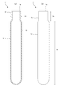
- FIGS. 3A and 3B are a front view and a front sectional view for explaining a step of inserting the blood collection tube of the embodiment of the present invention into the blood collection holder.
- FIGS. 1A and 1B are a front sectional view and a front view of a tubular body according to an embodiment of the present invention.
- the tube 1 is an open end 1a having an opening at one end.
- the other end is closed as a hemispherical bottom. And the whole is a substantially cylindrical shape.
- the small-diameter portion 1b having a relatively small outer diameter and the large-diameter portion 1c having a relatively large outer diameter are connected to the open end 1a in the vicinity of the open end 1a.
- the direction connecting the open end 1a and the bottom is the length direction.
- the tube 1 can be manufactured by injection blow molding of synthetic resin.
- the injection blow molding of the present invention includes a preform process and a blow molding process described below as essential processes. As an example, each process of injection blow molding will be described.
- Preform A cylindrical injection-molded preform is molded by injection molding of synthetic resin.
- This preform has a cylindrical shape in which one end is an open end and the other end is closed. That is, the outer diameter of the cylindrical portion is constant.
- the plastic preform obtained in the previous step is mounted on a mold and molded while injecting air from the mouth. More specifically, a mold capable of fixing the opening end and the vicinity of the opening end of the preform so that the diameter does not change is prepared as a mold. A preform is set in this mold, a gas such as air is injected from the opening end, and the shape is changed so as to increase the diameter of the large diameter portion. That is, the shape of the preform is changed so as to spread radially outward from the central axis of the tube, and the tube 1 shown in FIGS. 1A and 1B can be obtained.
- the ratio C2 / C1 between the outer diameter C2 of the large diameter portion 1c and the outer diameter C1 of the small diameter portion 1b shown in FIG. 1 (a) is preferably 1.1 to 1.5. In order for this ratio to exceed 1.5, it is necessary to relatively increase the outer diameter of the large diameter portion, but it becomes difficult to insert a widely used automatic analyzer into the tube rack. Further, if this ratio is smaller than 1.1, the thickness of the portion of the plug body that is sheathed on the tube body cannot be increased so much, and it is desirable that the ratio is 1.1 to 1.5.
- the outer diameter C1 of the small diameter portion is 11 to 14 mm
- the outer diameter C2 of the large diameter portion is 14 to 17 mm
- the tube length is 95 to 105 mm.
- the average thickness of a pipe body be an average value of the thickness obtained by measuring 10 places at intervals of 8 mm from the position which went down from the opening part of the pipe body to 20 mm.
- the tube average thickness of the tube of the present invention is preferably 0.5 to 1.5 mm. If the thickness is less than 0.5 mm, there is a problem that sufficient strength cannot be secured. If the thickness is more than 1.5 mm, it is difficult to secure a sufficient amount of sample collection because the internal volume is reduced, so 0.5 to 1 .5mm is desirable.
- the length C5 of the small diameter portion 1b is preferably 5 to 20 mm, and the length C6 of the large diameter portion 1c is preferably 80 to 95 mm.
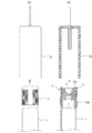
- FIGS. 2A and 2B show an example of such a plug.
- the plug body 11 has a plug body 12 made of rubber, elastomer or the like.
- the lower end portion of the plug body 12 is a portion that is press-fitted into the open end of the tube body.
- a cover member 13 is attached to the outside of the plug body 12.
- the cover member 13 has an annular flange portion 13a having a through hole in the center and a cover portion 13b extending downward from the outer peripheral edge of the annular flange portion 13a, which is located on the upper surface of the plug body 12.
- the cover portion 13 b is a portion that is externally attached to the small diameter portion 1 b of the tube body 1 when the plug body 11 is attached to the tube body 1. Since the cover portion 13b is provided, even when blood is about to scatter when the cover portion 13b is detached from the tube body 1, it is regulated by the cover portion 13b. Therefore, the safety of the inspection worker can be improved.
- the maximum outer diameter of the blood collection tube is increased by the thickness of the cover portion 13b.
- the outer diameter of the small diameter portion 1b is made smaller than that of the large diameter portion 1c. Therefore, at least a part of the thickness of the cover portion 13b can be absorbed by the difference in the outer diameter.
- the plug body provided with such a cover is an overcap type plug body.
- An overcap type plug body has a greater effect of preventing blood scattering at the time of opening than when a rubber plug type or film plug type plug body is used.
- a blood collection tube safer for the handler can be provided.
- the blood collection tube of the present embodiment has a structure in which the plug 11 is attached to the tube 1 as shown in FIGS. 3 (a) and 3 (b).
- the exterior portion of the plug body 11, that is, the cover portion 13 b is located outside the outer peripheral surface of the small diameter portion 1 b of the tube body 1.
- the blood collection tube is inserted from the opening below the blood collection holder 21.
- the blood collection holder that can use the blood collection tube of the present invention, but a blood collection holder having an inner diameter of 17 mm to 18 mm can be particularly preferably used. Since the internal diameter of blood collection holders widely used in Japan is 17 mm, the tube of the present invention can be used in many holders used in Japan.
- the tubular body of the present invention manufactured by blow molding so as to have the above-described structure has a characteristic that the impact strength at ⁇ 20 ° C. is higher than that of the tubular body manufactured by injection molding. Can be handled safely with little damage.
- Example 1 An injection molded preform having a tube body outer diameter of 13 mm was prepared using PET resin as a raw material. The obtained preform is heated and blow-molded, the tube small diameter part outer diameter C1 is 13 mm, the large diameter part maximum outer diameter C2 is 16 mm, the tube length is 100 mm, and the tube average wall thickness is 0.8 mm. Body 1 was obtained. The ratio C2 / C1 between the maximum outer diameter and the outer diameter of the small diameter portion of the obtained tube 1 was 1.2.
- Comparative Example 2 A PET resin was used as a raw material, and one end was opened as in Comparative Example 1 by injection molding to obtain a cylindrical tube with a bottom.
- the outer diameter of the tube was 16 mm, the tube length was 100 mm, and the tube average thickness was 1 mm.
- overcap type plug can be fitted
- An overcap type plug body having a maximum outer diameter of the cover portion of 16.6 mm and a cover portion made of PE resin was fitted.
- the obtained tube was subjected to an impact test using a 3 kg weight in a low temperature environment of ⁇ 20 ° C. in accordance with JIS K7211-1 “Plastic-Hard Plastic Puncture Impact Test Method”. Among these, the impact strength at which 50% of the pipes to be measured were destroyed was defined as 50% fracture energy, and the value was measured. Based on the obtained value, the case where the 50% fracture energy exceeded 10 J was evaluated as “Good”, and the case where it did not exceed was evaluated as “Poor”.
- the tube of the present invention manufactured by blow molding had a characteristic that the impact strength at ⁇ 20 ° C. was higher than that of the tube manufactured by injection molding.
Landscapes
- Health & Medical Sciences (AREA)
- Life Sciences & Earth Sciences (AREA)
- Hematology (AREA)
- General Health & Medical Sciences (AREA)
- Molecular Biology (AREA)
- Heart & Thoracic Surgery (AREA)
- Veterinary Medicine (AREA)
- Physics & Mathematics (AREA)
- Public Health (AREA)
- Biophysics (AREA)
- Pathology (AREA)
- Engineering & Computer Science (AREA)
- Biomedical Technology (AREA)
- Animal Behavior & Ethology (AREA)
- Medical Informatics (AREA)
- Chemical & Material Sciences (AREA)
- Surgery (AREA)
- Clinical Laboratory Science (AREA)
- Analytical Chemistry (AREA)
- Chemical Kinetics & Catalysis (AREA)
- Measurement Of The Respiration, Hearing Ability, Form, And Blood Characteristics Of Living Organisms (AREA)
- Medical Preparation Storing Or Oral Administration Devices (AREA)
Abstract
採取試料の大容量化を図ることができ、肉厚の大きなカバー部を有する栓体に適用することができ、低温における耐衝撃性が高められている管体を提供する。 採血ホルダーに挿入されて用いられる管体1であって、一端が開口端1aであって、他端が閉じられた底部であり、開口端1aに連なる小径部の外径が、残りの部分である大径部1cの外径よりも小さくされており、合成樹脂の射出ブロー成型により得られた成型体からなる、管体1。
Description
本発明は、体液採取チューブ用の管体、採血管及び管体の製造方法に関し、より詳細には、筒状の採血ホルダーに挿入して用いる、開口部が密栓された体液採取用の管体、採血管及び管体の製造方法に関する。
血液などの体液を採取するために、採血管等が用いられている。一般的な採血管は、一端が開口されておりかつ他端が有底の円筒状の管体を有する。この管体の開口端がゴム栓などの栓体により閉じられている。
下記の特許文献1~2に示すように、従来、上記管体として円筒状の有底の管体が広く用いられている。
昨今の検査項目数の増加等の要因によって、医療現場ではより大容量の体液を採取できるような管体のニーズが高まっている。
ところで、採血等においては、検査従事者の安全性を確保する必要がある。そのため、上記採血管に用いられる栓体として、管体の開口部に圧入される部分だけでなく、管体の開口端部分の外周面を被覆するカバー部を有する栓体が用いられてきている。このような栓体では、カバー部が管体の開口端近傍部分に外装されることになる。そのため、カバー部が位置している部分において、採血管の最大外径が大きくなる。
他方、採血ホルダーの採血管が挿入される部分の内径は、規格により定まっている。大容量の体液を確保するために、採血管の管体の径を太くすると、採血管の最大外径部分が大きくなりすぎる。特に、上記カバー部付きの安全性に優れた栓体を管体に装着すると、採血管の最大外径部分はかなり大きくなる。そのため、採血ホルダーの内径よりも採血管の最大外径が大きくなりすぎ、このような採血ホルダーに挿入することができなくなる。
そのため、従来、安全性に優れたカバー部付きの栓体ではなく、最大外径部分の増大を招かないゴム栓やフィルム状の栓が管体の開口端を閉じるために用いられてきている。しかしながら、これらの栓体では、開封時に体液や血液が飛散しやすいという問題がある。
上記のとおり、従来、検査者の安全性の確保と、血液や体液の採取量の大容量化との両立を果たすことは困難であった。
また、従来の採血管では、サンプルを凍結保存する場合などのような低温環境下に置かれると、強度が低下し、取扱い等により破損しやすいという問題もあった。
本発明の目的は、管体に外装される部分の肉厚が厚い栓体を用いた場合であっても、採血ホルダーに挿入することが可能であり、検体の大容量化及び安全性の両立を図り得る管体、採血管及び該管体の製造方法を提供することにある。また、本発明の他の目的は、低温下における耐衝撃性が高められた管体、該管体を有する採血管及び管体の製造方法を提供することにある。
本発明のある広い局面によれば、開口端が栓体で閉じられ、かつホルダーに挿入されて体液の採取に用いられる、有底の円筒状の管体が提供される。本発明の管体では、一端が開口端であって、他端が閉じられた底部である。開口端に連なる開口端側部分の外径が残りの部分の外径よりも小さくされている小径部とされている。残りの部分が、相対的に外径の大きな大径部とされている。本発明の管体は、合成樹脂の射出ブロー成型により得られた成型体からなる。
本発明に係る管体のある特定の局面では、前記小径部の長さが、前記栓体の前記管体の周囲に外装されている部分の長さよりも長い。この場合には、栓体の管体へ外装される部分の肉厚の少なくとも一部が、上記大径部と小径部との外径の差により吸収され得る。従って、最大外径部分の大きさを小さくすることができる。
本発明に係る採血管は、ホルダーに挿入され、体液の採取に用いられる採血管であって、本発明に従って構成された管体と、前記管体の前記開口端に挿入され、かつ前記管体の前記小径部分に外装されている部分を有する栓体とを備える。
本発明に係る採血管のある特定の局面では、前記小径部の長さが、前記栓体の前記外装部分の長さよりも長い。
本発明に係る管体の製造方法では、本発明に従って構成された管体の製造方法であって、合成樹脂を射出成型し、一端が開口端とされており、他端が閉じられた有底部とされている円筒状のプリフォームを得る工程と、前記プリフォームを開口端側部分が固定される金型に装着し、開口端側からプリフォーム内部にガスを注入しつつ、プリフォームを上記開口端側部分を除く部分において長さ方向中心軸部分を中心として径方向外側に膨らませ、大径部分を形成する工程とを備える射出ブロー成型からなる。
本発明に係る管体によれば、合成樹脂の射出ブロー成型からなり、開口端側部分の外径が残りの部分の外径よりも小さくされている小径部とされており、残りの部分が相対的に外径の大きな大径部とされているため、管体の開口端に装着される栓体として管体に外装される部分の肉厚が厚い栓体を用いたとしても、栓体付きの採血管の最大外径部分の外径を小さくすることができる。従って、大径部分の径を大きくし、採取する血液や体液の大容量化を図った場合であっても、安全性に優れた外装部分の肉厚の厚い栓体を用いて管体を閉成することができる。よって、安全性の向上と、試料の大容量化の両立を図ることが可能となる。
加えて、上記小径部と大径部が連ねられた構造を有するため、低温下における耐衝撃性を高めることも可能となる。
以下、図面を参照しつつ、本発明の具体的な実施形態を説明することにより、本発明を明らかにする。
図1(a)及び(b)は、本発明の一実施形態に係る管体の正面断面図及び正面図である。
管体1は、一端が開口を有する開口端1aである。他端が半球状の底部として閉じられている。そして、全体が略円筒状である。もっとも、開口端1a近傍の開口端1aに連なり、外径が相対的に小さい小径部1bと、相対的に外径の大きな大径部1cとが連ねられている。開口端1aと底部とを結ぶ方向を長さ方向とする。
上記管体1は、合成樹脂の射出ブロー成型により製造することができる。本発明の射出ブロー成型は、以下に述べるプリフォーム工程と、ブロー成型工程とを必須の工程として備える。一例として、射出ブロー成型の各工程を説明する。
(1)プリフォーム
合成樹脂の射出成型により、円筒状の射出成型プリフォームを成型する。このプリフォームは、一端が開口端であり、他端が閉じられている円筒状の形状を有する。すなわち、円筒状の部分の外径は一定とされている。
合成樹脂の射出成型により、円筒状の射出成型プリフォームを成型する。このプリフォームは、一端が開口端であり、他端が閉じられている円筒状の形状を有する。すなわち、円筒状の部分の外径は一定とされている。
(2)プリフォーム加熱
前工程で生産されたプリフォームを加熱し、可塑性を増す。
前工程で生産されたプリフォームを加熱し、可塑性を増す。
(3)ブロー成型
前工程で得られた可塑性を有するプリフォームを金型に装着し、口部より空気を注入しつつ成型する。より具体的には、金型として、プリフォームの開口端及び開口端近傍部分を径が変化しないように固定し得る金型を用意する。この金型にプリフォームをセットし、開口端から空気などのガスを注入し、大径部の径が大きくなるように形状を変化させ、成型する。すなわち、管体の中心軸から径方向外側に広がるようにプリフォームの形状を変化させ、図1(a)及び(b)に示した管体1を得ることができる。
前工程で得られた可塑性を有するプリフォームを金型に装着し、口部より空気を注入しつつ成型する。より具体的には、金型として、プリフォームの開口端及び開口端近傍部分を径が変化しないように固定し得る金型を用意する。この金型にプリフォームをセットし、開口端から空気などのガスを注入し、大径部の径が大きくなるように形状を変化させ、成型する。すなわち、管体の中心軸から径方向外側に広がるようにプリフォームの形状を変化させ、図1(a)及び(b)に示した管体1を得ることができる。
(4)排出
金型から成型された管体1を外し、冷却する。
金型から成型された管体1を外し、冷却する。
図1(a)に示す大径部1cの外径C2と、小径部1bの外径C1との比C2/C1は、1.1~1.5であることが望ましい。この比が1.5を超えるには、相対的に大径部の外径を大きくする必要があるが、広く用いられている自動分析装置の管体ラックへの挿入が難しくなる。また、この比を1.1より小さくすると、栓体の管体へ外装される部分の肉厚をあまり厚くできないため、1.1~1.5である事が望ましい。
具体的な数値としては、小径部の外径C1は11~14mm、大径部の外径C2は14~17mm、管長は95~105mmがそれぞれ望ましい。この範囲内の値にすることにより、広く用いられている自動分析装置の搬送装置に適用することが可能となり、従来の管体と同様の検査用途に使用することができる。
なお、管体の平均肉厚は、管体開口部より20mm底部へ下がった位置より8mm間隔で10箇所で測定して得られた肉厚の平均値とする。
本発明の管体の管体平均肉厚は0.5~1.5mmであることが望ましい。0.5mmより薄くすると、充分な強度を確保できない問題があり、1.5mmより厚くすると、内容積が少なくなることで充分な検体採取量を確保することが難しくなるため、0.5~1.5mmであることが望ましい。
小径部1bの長さC5は5~20mm、大径部1cの長さC6は80~95mmであることがそれぞれ好ましい。ただし、広く用いられている自動分析装置において搬送装置に適用させるためには、C5+C6=100±5mmの式が成立する必要がある。また、小径部1bの長さC5が長すぎると、大径部1cを短くしなければならない。従って、内容積が少なくなり、充分な検体採取量を確保することが難しくなる。
本発明の管体に使用できる栓体としては特に制限はないが、一体化された上部フランジを有する環状キャップ部と、キャップ部外面に被さるカバー部から構成された、いわゆるオーバーキャップタイプの栓体がより好適に使用できる。図2(a)及び(b)に、このような栓体の一例を示す。
図2(a)及び(b)に示すように、栓体11は、ゴムやエラストマーなどからなる栓本体12を有する。栓本体12の下端部分は、管体の開口端に圧入される部分である。
栓本体12の外側に、カバー部材13が装着されている。カバー部材13は、栓本体12の上面に位置している、中央に貫通孔を有する円環状のフランジ部13aと、円環状のフランジ部13aの外周縁から下方に延びるカバー部13bを有する。カバー部13bは、栓体11が管体1に装着された際に、管体1の小径部1bに外装される部分である。このカバー部13bが設けられているため、管体1から取り外した際に、血液が飛び散ろうとしたとしても、カバー部13bにより規制される。そのため、検査従事者の安全性を高めることができる。
上記栓体11では、カバー部13bが設けられているため、カバー部13bの肉厚分だけ、採血管の最大外径が大きくなる。
しかしながら、本実施形態では、上記小径部1bの外径が大径部1cよりも小さくされている。従って、上記カバー部13bの肉厚の少なくとも一部を、上記外径の差により吸収することができる。
このようなカバー部が設けられている栓体をオーバーキャップタイプの栓体というものとする。オーバーキャップタイプの栓体では、ゴム栓タイプやフィルム栓タイプの栓体を用いた場合よりも開封時の血液の飛散を防止する効果が大きい。取扱者にとってより安全な採血管を提供することができる。
本実施形態の採血管は、図3(a)及び(b)に示すように、上記管体1に上記栓体11が装着されている構造を有する。ここでは、栓体11の外装部分、すなわちカバー部13bが、管体1の小径部1bの外周面の外側に位置していることになる。
図3(a)及び(b)に示すように、使用に際しては、採血ホルダー21の下方の開口から上記採血管を挿入する。
本発明の採血管を使用できる採血ホルダーに特に制限はないが、内径が17mm~18mmの採血ホルダーが特に好適に使用できる。国内で広く用いられている採血ホルダーの内径は17mmのものが多いため、本発明の管体は日本国内で用いられるホルダーの多くに用いることができる。
また、上記構成を具備するようにブロー成形で製造した本発明の管体は、射出成形で製造した管体に対して-20℃での衝撃強度が高いという特性を有しており、取り扱い時の破損が少なく安全に取り扱いすることができる。
以下実施例において本発明を説明するが、本発明はこの態様に限定されるものではない。
(実施例1)
PET樹脂を原料とし、管体最大外径13mmの射出成型プリフォームを作成した。得られたプリフォームを加熱、ブロー成型し、管体小径部外径C1は13mm、大径部の最大外径C2は16mm、管長は100mm、管体平均肉厚は0.8mmである、管体1を得た。得られた管体1の最大外径と小径部外径との比C2/C1は1.2であった。
PET樹脂を原料とし、管体最大外径13mmの射出成型プリフォームを作成した。得られたプリフォームを加熱、ブロー成型し、管体小径部外径C1は13mm、大径部の最大外径C2は16mm、管長は100mm、管体平均肉厚は0.8mmである、管体1を得た。得られた管体1の最大外径と小径部外径との比C2/C1は1.2であった。
(比較例1)
PET樹脂を原料とし、射出成型により、一端が開口されて円筒状の有底の管体を得た。円筒部分の外径は13mmであり、管長は100mm、管体平均肉厚は1mmとした。
PET樹脂を原料とし、射出成型により、一端が開口されて円筒状の有底の管体を得た。円筒部分の外径は13mmであり、管長は100mm、管体平均肉厚は1mmとした。
(比較例2)
PET樹脂を原料とし、射出成型により、比較例1と同様に一端が開口されており、有底の円筒状の管体を得た。管体の外径は16mm、管長は100mm、管体平均肉厚は1mmとした。
PET樹脂を原料とし、射出成型により、比較例1と同様に一端が開口されており、有底の円筒状の管体を得た。管体の外径は16mm、管長は100mm、管体平均肉厚は1mmとした。
(実施例及び比較例の評価)
得られた管体について以下の方法で評価した。評価の結果は表1に記す。
得られた管体について以下の方法で評価した。評価の結果は表1に記す。
(オーバーキャップタイプ栓体の嵌合可否)
カバー部の最大外径が16.6mmで、カバー部の材質がPE樹脂からなるオーバーキャップタイプの栓体を嵌合し、嵌合可能ならば○、嵌合不可能ならば×で評価した。
カバー部の最大外径が16.6mmで、カバー部の材質がPE樹脂からなるオーバーキャップタイプの栓体を嵌合し、嵌合可能ならば○、嵌合不可能ならば×で評価した。
(50%破壊エネルギー)
得られた管体に対し、-20℃の低温環境においてJIS K7211-1「プラスチック-硬質プラスチックのパンクチャー衝撃試験方法」に則り、衝撃試験を3kgの錘を用いて行った。このうち、測定対象のうち50%の管体が破壊される衝撃強度を50%破壊エネルギーと定義し、その値を測定した。得られた値を元に、50%破壊エネルギーが10Jを超えるものに関しては○で、超えないものに関しては×で評価した。
得られた管体に対し、-20℃の低温環境においてJIS K7211-1「プラスチック-硬質プラスチックのパンクチャー衝撃試験方法」に則り、衝撃試験を3kgの錘を用いて行った。このうち、測定対象のうち50%の管体が破壊される衝撃強度を50%破壊エネルギーと定義し、その値を測定した。得られた値を元に、50%破壊エネルギーが10Jを超えるものに関しては○で、超えないものに関しては×で評価した。
ブロー成形で製造した本発明の管体は、射出成形で製造した管体に対して-20℃での衝撃強度が高いという特性を有していた。

1…管体
1a…開口端
1b…小径部
1c…大径部
11…栓体
12…栓本体
13…カバー部材
13a…フランジ部
13b…カバー部
21…採血ホルダー
1a…開口端
1b…小径部
1c…大径部
11…栓体
12…栓本体
13…カバー部材
13a…フランジ部
13b…カバー部
21…採血ホルダー
Claims (5)
- 開口端が栓体で閉じられ、かつホルダーに挿入されて体液の採取に用いられる有底の円筒状の管体であって、
一端が開口端であって、他端が閉じられた底部であり、開口端に連なる開口端側部分の外径が残りの部分の外径よりも小さくされている小径部とされており、残りの部分が相対的に外径の大きな大径部とされており、合成樹脂の射出ブロー成型により得られた成型体からなる、管体。 - 前記小径部の長さが、前記栓体の前記管体の周囲に外装されている部分の長さよりも長い、請求項1に記載の管体。
- ホルダーに挿入され、体液の採取に用いられる採血管であって、
請求項1または2に記載の管体と、
前記管体の前記開口端に挿入され、かつ前記管体の前記小径部分に外装されている部分を有する栓体とを備える、採血管。 - 前記小径部の長さが、前記栓体の前記外装部分の長さよりも長い、請求項3に記載の採血管。
- 請求項1または2に記載の管体の製造方法であって、
合成樹脂を射出成型し、一端が開口端とされており、他端が閉じられた有底部とされている円筒状のプリフォームを得る工程と、
前記プリフォームを開口端側部分が固定される金型に装着し、開口端側からプリフォーム内部にガスを注入しつつ、プリフォームを前記開口端側部分を除く部分において長さ方向中心軸部分を中心として径方向外側に膨らませ、大径部分を形成する工程とを備える、管体の製造方法。
Priority Applications (1)
| Application Number | Priority Date | Filing Date | Title |
|---|---|---|---|
| JP2014538623A JPWO2014051037A1 (ja) | 2012-09-28 | 2013-09-27 | 管体、採血管及び管体の製造方法 |
Applications Claiming Priority (2)
| Application Number | Priority Date | Filing Date | Title |
|---|---|---|---|
| JP2012-215642 | 2012-09-28 | ||
| JP2012215642 | 2012-09-28 |
Publications (1)
| Publication Number | Publication Date |
|---|---|
| WO2014051037A1 true WO2014051037A1 (ja) | 2014-04-03 |
Family
ID=50388431
Family Applications (1)
| Application Number | Title | Priority Date | Filing Date |
|---|---|---|---|
| PCT/JP2013/076225 Ceased WO2014051037A1 (ja) | 2012-09-28 | 2013-09-27 | 管体、採血管及び管体の製造方法 |
Country Status (2)
| Country | Link |
|---|---|
| JP (1) | JPWO2014051037A1 (ja) |
| WO (1) | WO2014051037A1 (ja) |
Cited By (4)
| Publication number | Priority date | Publication date | Assignee | Title |
|---|---|---|---|---|
| CN109507178A (zh) * | 2018-12-25 | 2019-03-22 | 菏泽学院 | 一种环保型微生物吲哚试验仪 |
| WO2020106225A3 (en) * | 2018-11-19 | 2020-06-25 | Turajane Thana | Round-bottom tube with a triple-lock stopper |
| EP3573759A4 (en) * | 2017-01-25 | 2020-07-29 | Yantai AusBio Laboratories Co., Ltd. | EQUIPMENT AND METHODS FOR AUTOMATED SAMPLE PROCESSING FOR DIAGNOSTIC PURPOSES |
| US12434889B2 (en) | 2022-12-09 | 2025-10-07 | Instrumentation Laboratory Company | Sealing systems |
Citations (2)
| Publication number | Priority date | Publication date | Assignee | Title |
|---|---|---|---|---|
| JPS55500937A (ja) * | 1978-11-28 | 1980-11-13 | ||
| JPS61128944A (ja) * | 1984-11-27 | 1986-06-17 | テルモ株式会社 | 減圧採血管 |
Family Cites Families (1)
| Publication number | Priority date | Publication date | Assignee | Title |
|---|---|---|---|---|
| JP2011073762A (ja) * | 2009-09-30 | 2011-04-14 | Kyoraku Co Ltd | 樹脂製容器およびその製造方法 |
-
2013
- 2013-09-27 WO PCT/JP2013/076225 patent/WO2014051037A1/ja not_active Ceased
- 2013-09-27 JP JP2014538623A patent/JPWO2014051037A1/ja active Pending
Patent Citations (2)
| Publication number | Priority date | Publication date | Assignee | Title |
|---|---|---|---|---|
| JPS55500937A (ja) * | 1978-11-28 | 1980-11-13 | ||
| JPS61128944A (ja) * | 1984-11-27 | 1986-06-17 | テルモ株式会社 | 減圧採血管 |
Cited By (6)
| Publication number | Priority date | Publication date | Assignee | Title |
|---|---|---|---|---|
| EP3573759A4 (en) * | 2017-01-25 | 2020-07-29 | Yantai AusBio Laboratories Co., Ltd. | EQUIPMENT AND METHODS FOR AUTOMATED SAMPLE PROCESSING FOR DIAGNOSTIC PURPOSES |
| US11883817B2 (en) | 2017-01-25 | 2024-01-30 | Yantai Ausbio Laboratories Co., Ltd. | Equipment and methods for automated sample processing for diagnostic purposes |
| WO2020106225A3 (en) * | 2018-11-19 | 2020-06-25 | Turajane Thana | Round-bottom tube with a triple-lock stopper |
| CN109507178A (zh) * | 2018-12-25 | 2019-03-22 | 菏泽学院 | 一种环保型微生物吲哚试验仪 |
| CN109507178B (zh) * | 2018-12-25 | 2021-03-19 | 菏泽学院 | 一种环保型微生物吲哚试验仪 |
| US12434889B2 (en) | 2022-12-09 | 2025-10-07 | Instrumentation Laboratory Company | Sealing systems |
Also Published As
| Publication number | Publication date |
|---|---|
| JPWO2014051037A1 (ja) | 2016-08-22 |
Similar Documents
| Publication | Publication Date | Title |
|---|---|---|
| Chen et al. | Interfacial characteristics of carbon nanotube-polymer composites: A review | |
| WO2014051037A1 (ja) | 管体、採血管及び管体の製造方法 | |
| CN104066384A (zh) | 用于流体样本容器的安全护罩 | |
| US10273037B2 (en) | Reusable packaging and storage | |
| WO2015118076A3 (en) | Sample collection tubes | |
| US20150174337A1 (en) | Elastic cap and syringe assembly therewith | |
| MY168339A (en) | Preform and plastic bottle | |
| EP2450682A3 (de) | Temperatursensorvorrichtung und Verfahren zum Herstellen einer Temperatursensorvorrichtung | |
| US8540424B2 (en) | Cover for shaft of electronic thermometer probe | |
| CN205449529U (zh) | 粪便取样装置 | |
| CN104013413B (zh) | 一种一次性真空采血管 | |
| CN204318770U (zh) | 一种真空采血管的胶塞盖 | |
| EP1394061A2 (en) | Sealing closure plug | |
| CN205216874U (zh) | 一种分体式离心管 | |
| CN209952896U (zh) | 一种体液送检试管 | |
| CN211253592U (zh) | 试剂瓶盖 | |
| CN207779291U (zh) | 非标准圆形钨片内外径检验工具 | |
| CN205483694U (zh) | 尿荧光原位杂交标本收集瓶 | |
| CN210375961U (zh) | 一种用于环境应力开裂检测的新型试管 | |
| CN206151588U (zh) | 一种监护仪探头保护罩 | |
| CN204746352U (zh) | 一种血清检测试管 | |
| CN103204312A (zh) | 改进型酒精棉球瓶 | |
| RU122987U1 (ru) | Пробка для укупорки сосудов | |
| CN203955253U (zh) | 一种用于内科检验用试管 | |
| CN207717417U (zh) | 一种尿检采样装置 |
Legal Events
| Date | Code | Title | Description |
|---|---|---|---|
| 121 | Ep: the epo has been informed by wipo that ep was designated in this application |
Ref document number: 13841244 Country of ref document: EP Kind code of ref document: A1 |
|
| ENP | Entry into the national phase |
Ref document number: 2014538623 Country of ref document: JP Kind code of ref document: A |
|
| NENP | Non-entry into the national phase |
Ref country code: DE |
|
| 122 | Ep: pct application non-entry in european phase |
Ref document number: 13841244 Country of ref document: EP Kind code of ref document: A1 |