WO2014050976A1 - Needleless connector - Google Patents
Needleless connector Download PDFInfo
- Publication number
- WO2014050976A1 WO2014050976A1 PCT/JP2013/076084 JP2013076084W WO2014050976A1 WO 2014050976 A1 WO2014050976 A1 WO 2014050976A1 JP 2013076084 W JP2013076084 W JP 2013076084W WO 2014050976 A1 WO2014050976 A1 WO 2014050976A1
- Authority
- WO
- WIPO (PCT)
- Prior art keywords
- valve body
- elastic valve
- support surface
- needleless connector
- outer peripheral
- Prior art date
Links
Images


Classifications
-
- A—HUMAN NECESSITIES
- A61—MEDICAL OR VETERINARY SCIENCE; HYGIENE
- A61M—DEVICES FOR INTRODUCING MEDIA INTO, OR ONTO, THE BODY; DEVICES FOR TRANSDUCING BODY MEDIA OR FOR TAKING MEDIA FROM THE BODY; DEVICES FOR PRODUCING OR ENDING SLEEP OR STUPOR
- A61M39/00—Tubes, tube connectors, tube couplings, valves, access sites or the like, specially adapted for medical use
- A61M39/22—Valves or arrangement of valves
- A61M39/26—Valves closing automatically on disconnecting the line and opening on reconnection thereof
- A61M2039/261—Valves closing automatically on disconnecting the line and opening on reconnection thereof where the fluid space within the valve is increasing upon disconnection
-
- A—HUMAN NECESSITIES
- A61—MEDICAL OR VETERINARY SCIENCE; HYGIENE
- A61M—DEVICES FOR INTRODUCING MEDIA INTO, OR ONTO, THE BODY; DEVICES FOR TRANSDUCING BODY MEDIA OR FOR TAKING MEDIA FROM THE BODY; DEVICES FOR PRODUCING OR ENDING SLEEP OR STUPOR
- A61M39/00—Tubes, tube connectors, tube couplings, valves, access sites or the like, specially adapted for medical use
- A61M39/02—Access sites
- A61M39/04—Access sites having pierceable self-sealing members
- A61M39/045—Access sites having pierceable self-sealing members pre-slit to be pierced by blunt instrument
Definitions
- the present invention relates to a needleless connector that is used in a liquid flow path such as an infusion route in the medical field and that can connect a male luer provided in a syringe or the like to the liquid flow path.
- a needleless connector In a liquid flow path for performing infusion or blood transfusion in the medical field, a needleless connector is used to enable connection and disconnection of a syringe, an infusion bag, and the like.
- this needleless connector as shown in FIG. 1 of US Pat. No. 6,171,287 (Patent Document 1), an elastic valve body is assembled to the tip opening of a chemical flow path formed in the housing. .
- a catheter inserted into a blood vessel is connected to the proximal end of the drug solution flow path.
- the elastic valve body is opened so that the chemical flow path and the male luer are communicated.
- the drug solution can be administered to the patient by flowing the drug solution into the needleless connector from a syringe or the like connected to the male luer.
- the male luer is extracted from the slit, and the slit is closed as the elastic valve body is restored.
- the distal end opening of the chemical liquid flow path is blocked by the elastic valve body, and the male luer is separated from the chemical liquid flow path connected to the blood vessel or the like.
- the needleless connector described in Patent Document 1 has a conventional structure, and the tip opening of the chemical liquid channel gradually spreads toward the elastic valve body.
- the end face of the elastic valve body on the side of the chemical liquid flow path is not supported, and when the male luer is inserted from the outside, the elastic valve element is elastic so that the central part of the elastic valve body enters inward from the tip opening of the chemical liquid flow path. Deform.
- the male luer is pulled out, the volume of the chemical liquid channel connected to the blood vessel or the like increases with the restoring deformation of the elastic valve body, and the suction force of blood or the like to the chemical liquid channel is generated. Blood regurgitation was easy to occur.
- Patent Document 2 proposes a structure in which an inner chamber is formed and a hard member is embedded in a partition wall that is a valve body. Has been.
- the volume of the inner chamber decreases when the tip portion is removed by inserting the tip portion of the male luer or the like and increasing the volume of the inner chamber along with the elastic deformation of the partition wall. Thus, backflow of blood or the like is prevented.
- the present invention has been made in the background as described above, and the problem to be solved is to provide a novel needleless connector that can prevent backflow of blood or the like with a simple structure. There is to do.
- the first aspect of the present invention made to solve such a problem is that an elastic valve body is incorporated in a housing in which a chemical liquid flow path is formed, and a male luer is inserted into the slit of the elastic valve body.
- the housing is formed with a projecting support surface having an inclined surface spreading toward the bottom.
- the elastic valve body is superposed in close contact with the support surface, and the slit of the elastic valve body is positioned over the opening of the chemical liquid channel on the projecting support surface.
- the outer peripheral surface of the elastic valve body, which is superimposed on the support surface is unevenly formed to form valleys and peaks that extend in the circumferential direction.
- the elastic valve body is superposed in close contact with the projecting support surface, so that when the male luer is inserted, the elastic valve body extends along the projecting support surface in the slit expanding direction. It is stretched and elastically deformed.
- the elastic valve element is prevented from entering the liquid chemical flow channel when the male luer is inserted, and the volume between the elastic valve element and the protruding support surface is reliably increased by the amount of the slit. Therefore, when the male lure is extracted, the volume reduction amount corresponding to the amount of the slit that has spread will generate a positive pressure (positive pressure) in the chemical flow path, effectively preventing backflow of blood, etc. Can work.
- the trough and the crest are formed on the outer peripheral surface of the elastic valve body that is in close contact with the protruding support surface, so that the elasticity of the elastic valve body is partially A part that is different and easily deformed is formed. Therefore, when the elastic valve body is deformed along the projecting support surface when the male luer is inserted, it is bent away from the projecting support surface so as to bend at the portion that is easily deformed by the valley. Bending deformation is likely to occur.
- the elastic valve body is bent and deformed so as to be separated from the projecting support surface outward, so that the gap between the elastic valve body closely contacted in the initial state and the projecting support surface is reliably stabilized. It tends to occur.
- the volume increase in the elastic valve body when the male luer is inserted can be realized in a large and stable manner, and a larger positive pressure is applied to the chemical flow path when the male luer is removed. It can be generated to further improve the effect of preventing the backflow of blood or the like.
- the valley and the peak are relative height portions on the outer peripheral surface of the elastic valve body, the relatively concave portion is referred to as a valley portion, and the relatively convex portion is referred to as a relatively convex portion. It is called Yamabe. Further, the valley and the mountain do not need to be adjacent to each other, and may be provided apart from each other, and the number and shape are not limited.
- a second aspect of the present invention is the needleless connector according to the first aspect, wherein the irregularities on the outer peripheral surface of the elastic valve body have a smooth curved cross-sectional shape having no corners. It is.
- the needleless connector according to the first or second aspect, wherein the elastic valve body is superposed on a skirt side region of the projecting support surface; And a thick portion that is overlapped with the top region of the projecting support surface.
- the valley portion is formed on the outer peripheral surface of the upper end portion of the thick portion.
- a soft deformation is realized in the thick part of the elastic valve body, which tends to have a large deformation rigidity due to an increase in the thickness dimension, thereby facilitating insertion of the male luer. Become.
- a fourth aspect of the present invention is the needleless connector according to any one of the first to third aspects, wherein the elastic valve body is overlapped with a skirt side region of the projecting support surface; A thick portion that is superimposed on the top region of the projecting support surface, and at least the valley portion and the crest portion are formed on the outer peripheral surface of the thick portion. is there.
- the slit blocking characteristics required by adjusting the size, shape, number, etc. of the valleys and peaks provided on the outer peripheral surface of the thick part of the elastic valve body which tends to have high deformation rigidity.
- the male luer insertion operability, and the backflow preventing action of blood or the like when the male luer is pulled out can be set more appropriately and with a large degree of freedom.
- the ease of deforming realized by the valley is used to facilitate the insertion operation of the male luer, while the elastic strength realized by the peak is used to ensure the slit blocking, and the valley It is possible to obtain an excellent backflow prevention effect when the male luer is pulled out by utilizing the stable outward bulging deformation realized by the cooperation of the mountain part.
- the needleless connector according to any one of the first to fourth aspects, wherein the elastic valve body is overlapped with a skirt side region of the protruding support surface; , And a thick portion that is superimposed on the top region of the projecting support surface, and the valley portion and the peak portion are formed at least on the outer peripheral surface of the thin portion.
- a sixth aspect of the present invention is the needleless connector according to any one of the first to fifth aspects, wherein the valley portion and the mountain portion are provided over the entire outer circumference of the elastic valve body. It is what has been.
- the male luer can be inserted. It is possible to further increase the outward deformation of the elastic valve body during insertion. As a result, when the male luer is withdrawn, a larger positive pressure is generated in the drug solution flow path, and the effect of preventing the backflow of blood or the like can be further improved.
- a seventh aspect of the present invention is the needleless connector according to any one of the first to sixth aspects, wherein an outer periphery of the elastic valve body is covered with the housing, and the elastic valve body and the housing Is provided with an internal space that allows deformation of the elastic valve body toward the outer peripheral side.
- the eighth aspect of the present invention is the needleless connector according to the seventh aspect, in which a space communication path is formed for communicating the internal space with the external space.
- the elastic valve body when the elastic valve body is expanded and deformed by inserting the male luer, deformation resistance due to the air spring in the deformation-permitting space is avoided.
- the male luer can be more easily inserted into the elastic valve body, and a gap between the elastic valve body and the projecting support surface is more easily generated, so that blood or the like flows backward when the male luer is extracted. Further improvement of the prevention effect is also achieved.
- a ninth aspect of the present invention is the needleless connector according to any one of the first to eighth aspects, wherein the elastic valve body includes a pair of openings that extend to the outer peripheral side at both end portions in the penetration direction of the slit.
- a flange-like portion is integrally formed, and the outer peripheral edge portions of the pair of flange-like portions are each fixedly supported by the housing.
- the elastic valve body is fixedly supported on the housing by the pair of flange-shaped portions, thereby easily and highly ensuring fluid tightness with respect to the external space of the chemical liquid flow path formed in the slit of the elastic valve body. It becomes possible.
- a tenth aspect of the present invention is the needleless connector according to any one of the first to ninth aspects, wherein a second valve body is provided so as to overlap the outer end surface of the elastic valve body, A slit provided in the second valve body and into which the male luer is inserted is formed in a direction overlapping and overlapping the slit of the elastic valve body.
- the slit is opened and closed based on the elastic deformation accompanying the insertion and removal of the male luer, and the communication / blocking of the chemical liquid flow path is switched.
- An eleventh aspect of the present invention is the needleless connector according to any one of the first to tenth aspects, wherein at least a tip portion of the projecting support surface has a long mountain shape extending with a ridgeline top. At the same time, the slits of the elastic valve body are overlapped in a state extending along the apex of the ridgeline.
- both side portions sandwiching the slit are formed in a ridge line shape of the projecting support surface. It will be elastically deformed in the direction of expanding the slit while being guided along the slopes on both sides across the top. For this reason, the guide action by the projecting support surface and the direction in which the slit opens are combined, so that the elastic deformation of the elastic valve body occurs more efficiently and stably. As a result, a larger gap is stably generated between the elastic valve body and the projecting support surface by inserting the male luer, and the backflow prevention of blood or the like during the extraction of the male luer is more effectively achieved.
- a twelfth aspect of the present invention is the needleless connector according to any one of the first to eleventh aspects, wherein a tip end portion opened to a top portion of the protruding support surface in the chemical liquid flow path has a cross-sectional area. The nozzle shape is narrowed down.
- the tip opening of the chemical liquid channel that opens to the projecting support surface has a small opening area, there are more problems such as the elastic valve element entering the tip opening when the male luer is inserted. Effectively prevented.
- the trough and the crest are provided on the outer peripheral surface of the elastic valve body so that it is bent near the trough that is easily deformed when the male luer is inserted.
- the elastic valve body is deformed.
- elastic deformation in a direction away from the projecting support surface occurs with a stable shape, and a predetermined gap is provided between the elastic valve body and the projecting support surface when the male luer is inserted. Occurs stably.
- the effect of preventing the backflow of blood and the like is effectively and stably exhibited by the positive pressure generated based on the disappearance of the gap when the male luer is extracted.
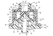
- FIG. 1 is a longitudinal sectional view of a needleless connector as a first embodiment of the present invention.
- II-II sectional drawing of FIG. The perspective view of the base housing which comprises the needleless connector shown by FIG.
- the perspective view of the elastic valve body which comprises the needleless connector shown by FIG. The front view of the elastic valve body shown by FIG.
- Explanatory drawing which shows the insertion state of the male luer in the needleless connector shown by FIG.
- the longitudinal cross-sectional view of the needleless connector as the 2nd Embodiment of this invention.
- XI-XI sectional drawing of FIG. The perspective view of the elastic valve body which comprises the needleless connector shown by FIG.
- FIGS. 1 and 2 show a needleless connector 10 as a first embodiment of the present invention.
- the needleless connector 10 has a structure in which a lower valve 14 as an elastic valve body and an upper valve 16 as a second valve body are incorporated in a housing 12.
- the vertical direction refers to the vertical direction in FIGS.
- the housing 12 has a divided structure, and includes a base housing 18 on the base end side that is the lower side in FIG. 1 and a cover housing 20 on the front end side that is the upper side in FIG. .
- the base housing 18 is provided with a peripheral wall portion 24 apart from the outer peripheral side of the cylindrical portion 22 extending on the central axis, and the upper bottom portion 26 integrally connects between the cylindrical portion 22 and the upper end portion of the peripheral wall portion 24. It is connected. Further, the cylindrical portion 22 protrudes downward from the peripheral wall portion 24, and a chemical liquid channel 28 is formed inside the cylindrical portion 22. On the other hand, a lock groove 30 is formed on the inner peripheral surface of the peripheral wall portion 24.
- an intravascular indwelling catheter (not shown) is connected to the proximal end opening of the cylindrical portion 22 of the base housing 18.
- the cylindrical portion 22 and the peripheral wall portion 24 constitute a lock-type luer structure, so that the catheter can be reliably connected.
- a projecting support surface 32 is formed.
- a top portion 34 extending in the shape of a ridge line is formed at least at the tip portion (upward in FIG. 3) of the projecting support surface 32.
- the projecting support surface 32 has a long mountain shape as a whole.
- the chemical liquid channel 28 formed in the cylindrical portion 22 is opened at the upper tip portion, and is a nozzle-like tip opening portion 36 having a reduced cross-sectional area.
- the nozzle-like tip opening 36 opens at the center of the top 34 extending in a ridgeline shape on the projecting support surface 32.
- the projecting support surface 32 is a taper-shaped taper having a hem extending at a substantially constant inclination angle from the top to the skirt. It is an inclined surface. That is, the projecting support surface 32 is not provided with a folding point or a bending point at an intermediate portion in the height direction, and is an inclined surface extending substantially linearly in the vertical direction.
- the inclined surface of the projecting support surface 32 is not limited to a straight line, and may be curved, and one or more folding points or bending points may be provided in the middle of the height direction. You may have.
- a linear communication groove 37 extending downward from the top 34 is formed on the projecting support surface 32.
- a pair of communication grooves 37a, 37a are formed in the left-right direction in FIG. 1
- a pair of communication grooves 37b, 37b are formed in the left-right direction in FIG.
- the pair of communication grooves 37 b and 37 b are linearly formed extending from the distal end opening 36 of the chemical liquid flow channel 28 that is the center of the top portion 34 to the lower end skirt of the projecting support surface 32.
- An annular flat surface 38 (see FIG. 3) is formed on the upper end surface of the base housing 18 so that the outer peripheral side of the protruding support surface 32 extends in the circumferential direction with a predetermined width, and the outer peripheral edge of the flat surface 38.
- An outer peripheral collar 40 that protrudes upward in a cylindrical shape is formed integrally with the part.
- a step 42 for positioning and fixing the cover housing 20 is formed on the outer peripheral surface of the base housing 18.
- the cover housing 20 constituting the housing 12 in cooperation with such a base housing 18 has a stepped cylindrical shape as a whole as shown in FIGS. That is, in the cover housing 20, the cover main body 44 having a large-diameter cylindrical shape and the connection port portion 46 having a small-diameter cylindrical shape are integrally connected by the upper bottom portion 48 having an annular plate shape.
- the cover body 44 that opens downward is assembled from above the base housing 18, and the opening of the cover body 44 is fitted to the outer peripheral surface of the base housing 18.
- the opening portion of the cover main body 44 is fixed to the base housing 18 by fixing means such as press-fitting, welding, and adhesion while being positioned in the axial direction by the step 42 of the base housing 18.
- the cover housing 20 is assembled to the base housing 18, so that an internal region whose periphery is covered with the cover housing 20 is formed above the base housing 18. Further, the internal region is opened upward through the connection port portion 46 of the cover housing 20.
- a lock groove 50 is formed on the outer peripheral surface of the connection port portion 46.
- an air vent hole 52 penetrating inward and outward is formed in each peripheral wall of the cover body 44 and the connection port portion 46.
- the lower valve 14 and the upper valve 16 are incorporated into the inner region formed in the housing 12 as described above.
- the lower valve 14 has a valve main body 54 as a thick wall portion having a block shape, and an expansion having an outer peripheral surface shape that extends in a tapered shape below the valve main body. And a diameter portion 56.
- the shape of the outer peripheral surface of the valve main body 54 is not particularly limited, but in the present embodiment, it is a substantially elliptic cylinder.
- each one valley part 58 and peak part 60 are each formed in the annular
- the valley portion 58 is formed on the outer peripheral surface of the upper end portion of the valve main body portion 54, while the peak portion 60 is formed on the outer peripheral surface of the lower end portion of the valve main body portion 54.
- the entire lower valve 14 is also formed at the boundary portion between the valve main body portion 54 and the enlarged diameter portion 56.
- a trough 58 extending around the circumference is formed.
- the unevenness formed on the outer peripheral surface of the lower valve 14 is formed by a smooth curve having no corners.
- the outer peripheral surfaces of the valve main body portion 54 and the enlarged diameter portion 56 are formed into a smooth curved cross-sectional shape having no break points as a whole including the valley portions 58 and 58 and the peak portion 60.
- valve main body portion 54 indicates a virtual outer peripheral surface shape in which the concave and convex valley portions 58 and the peak portions 60 are not formed in the valve main body portion 54. That is, the outer peripheral surface shape of the valve main body 54 shown by the phantom line is an elliptical cylindrical base shape.
- a slit 62 is formed in the central portion of the valve main body portion 54 so as to penetrate in the vertical direction.
- the valve body portion 54 has an elliptical outer cross-sectional shape, and the slit 62 extends in the major axis direction of the ellipse.
- a pair of flange portions 64 and 64 are integrally formed on the outer peripheral surfaces of the upper and lower ends of the valve main body portion 54 at both end portions of the slit 62 in the penetrating direction, and spread outwardly.
- the upper end surface of the lower valve 14 is a flat surface, while the lower end surface is formed with a recess 66 that opens to the center portion.
- the shape of the inner peripheral surface of the recess 66 is a tapered surface shape corresponding to the protruding support surface 32 of the base housing 18 described above.
- the recess 66 has an elliptical tapered surface that gradually expands toward the opening at the lower end.
- the inner peripheral surface of the recess 66 has substantially the same inclination angle as the outer peripheral surface of the enlarged diameter portion 56. And the recessed part 66 is formed in the inside of the enlarged diameter part 56, and the enlarged diameter part 56 is made into the thin part of a taper cylinder shape. Note that the upper portion of the recess 66 extends to an intermediate portion in the axial direction of the valve main body 54 constituting the thick portion.
- the upper valve 16 includes a valve main body 68 having a substantially flat elliptical cross-sectional shape and extending in the vertical direction.
- a pair of flange portions 70 and 72 are integrally formed on the surface.
- a slit 74 is formed in the central portion of the valve main body 68 so as to penetrate in the vertical direction. The slit 74 extends in the major axis direction of the flat ellipse in the cross section of the upper valve 16 and penetrates linearly in the vertical direction.
- the lower valve 14 and the upper valve 16 are incorporated in the housing 12 in a state where the upper valve 16 is superimposed on the upper end surface (outer end surface) of the lower valve 14.
- the lower valve 14 is assembled in a state in which the projecting support surface 32 of the base housing 18 is fitted into the recess 66, and the inner surface of the recess 66 is the projecting support surface 32.
- the substantially entire surface is overlaid in a substantially close contact state. That is, the inner peripheral surface of the enlarged diameter portion 56 constituting the thin wall portion of the lower valve 14 is superimposed on the skirt side region of the protruding support surface 32 of the base housing 18, and the top side of the protruding support surface 32. In the region, a valve main body 54 constituting a thick portion in the lower valve 14 is overlaid.
- the lower flange portion 64 of the lower valve 14 is overlapped with the flat surface 38 of the base housing 18 on the outer peripheral side of the projecting support surface 32 in a substantially close contact state.
- a lower flange portion 72 of the upper valve 16 is overlapped with the upper flange portion 64 of the lower valve 14, and both flange portions 64 and 72 having substantially the same outer diameter are formed on the cover housing 20. It is superimposed on the lower surface of the upper bottom 48.
- a cylindrical holding sleeve 76 is incorporated in the housing 12 and is arranged in an extrapolated state on the valve body 54 of the lower valve 14.
- the pressing sleeve 76 is assembled between the upper and lower flange portions 64 and 64 of the lower valve 14 in a state where the lower end portion is fitted into the outer peripheral collar 40 of the base housing 18 and positioned.
- the height dimension (vertical direction in FIG. 1) of the pressing sleeve 76 is slightly larger than the distance between the opposing surfaces of the pair of upper and lower flange portions 64 and 64 of the lower valve 14.
- the outer peripheral portion of the lower flange portion 64 of the lower valve 14 is pressed against the flat surface 38 of the base housing 18 by the lower end surface in the axial direction of the pressing sleeve 76 and is fixed in a sealed manner.
- the outer peripheral portions of the upper flange portion 64 of the lower valve 14 and the lower flange portion 72 of the upper valve 16 that are overlapped with each other by the upper end surface in the axial direction of the pressing sleeve 76 are the upper bottom portion 48 of the cover housing 20. The seal is fixed by being pressed.
- the outer peripheral side of the valve main body 54 is deformed as an internal space that allows elastic deformation of the lower valve 14 toward the outer peripheral side.
- An allowable space 78 is formed.
- the pressing sleeve 76 is spaced outward from the outer peripheral surface of the valve main body 54 of the lower valve 14, and between the valve main body 54 and the pressing sleeve 76, that is, the lower valve 14.
- a deformation allowing space 78 is formed between the opposing surfaces of the pair of upper and lower flange portions 64, 64.
- the pressing sleeve 76 has one or a plurality of radial through holes 80 (two in the present embodiment) and a gap between the pressing sleeve 76 and the cover main body 44 of the cover housing 20. 82 is formed. Thus, a space communication path that connects the deformation allowing space 78 to the external space is formed by the through hole 80, the gap 82, and the air vent hole 52.
- the upper valve 16 has a valve main body 68 disposed in the connection port portion 46 of the cover housing 20, and an upper flange portion 70 of the upper valve 16 is superimposed on the upper opening end surface of the connection port portion 46. Yes.
- the elastic deformation of the valve main body 68 is permitted in a direction orthogonal to the direction in which the slit 74 extends (left and right direction in FIG. 1).
- a deformation allowable space 84 is formed.
- the lower valve 14 is aligned in the circumferential direction with respect to the base housing 18 so that the major axis direction of the valve main body 54 extends in the ridge line direction of the apex 34 that is formed into a long mountain shape on the projecting support surface 32. ing.
- the slit 62 as the valve hole of the lower valve 14 extends along the ridge-shaped top 34 of the projecting support surface 32 of the base housing 18.
- the slit 62 is in close contact before the male luer 88 described later is inserted, and is not open.
- the distal end opening 36 of the chemical liquid flow path 28 of the cylindrical portion 22 opens at the center of the top portion 34 that extends in a ridgeline shape on the protruding support surface 32. .
- the slit 74 as the valve hole of the upper valve 16 is positioned and assembled in the circumferential direction in a state extending in a direction substantially orthogonal to the slit 62 of the lower valve 14.
- the distal end opening 36 of the chemical flow path 28 of the base housing 18 is positioned on the central axis extending in the vertical direction through the intersection of the slit 62 of the lower valve 14 and the slit 74 of the upper valve 16. Yes.
- the needleless connector 10 having the above-described structure is used with an intravascular indwelling catheter or the like (not shown) connected to the proximal end opening of the drug solution flow path 28 as described above.
- the male luer 88 such as the syringe 86 enters the slits 74 and 62 of the upper valve 16 and the lower valve 14 through the connection port portion 46 of the housing 12 from above as shown in FIG. 9.
- the respective slits 74 and 62 are expanded, and the male luer 88 is brought into communication with the chemical liquid flow path 28.
- the male luer 88 of the syringe 86 shown in FIG. 9 has a male luer lock structure so that the connection state with respect to the connection port portion 46 of the housing 12 is reliably maintained.
- the male luer 88 may have not only a luer lock structure that is fixed with screws, but also a luer slip structure that is inserted and fixed.
- the pushing force of the male luer 88 is applied to the lower valve 14, and the central portion of the valve main body 54 of the lower valve 14 is pushed downward. It is done. Along with this depression, the lower surface of the valve main body 54 is deformed so as to be spread on both sides of the slit 62 along the protruding support surface 32 brought into a close contact state. At that time, in the lower valve 14, the elasticity is partially changed by the valley portion 58 and the peak portion 60 formed on the outer peripheral surface. Therefore, when the lower valve 14 is deformed along the projecting support surface 32 when the male luer 88 is inserted, the lower valve 14 is easily deformed by being bent by the valley portion 58.
- the deformation rigidity of the lower valve 14 when the male luer 88 is inserted is reduced, and the male luer 88 can be easily inserted.
- the curve near the valley portion 58 that is easily deformed and the shape retention near the mountain portion 60 that is difficult to deform cooperate with each other outward from the projecting support surface 32.
- the gap 90 is reliably and stably generated with a large volume between the lower valve 14 bent and deformed so as to be separated from the protruding support surface 32.
- the circumferentially extending gap 90 is formed by the pair of communication holes 37a and 37a and the pair of communication holes 37b and 37b formed on the projecting support surface 32.
- the slit 62 communicates more reliably and stably.
- the inclined surface forming the projecting support surface 32 is linear in the cross section in the vertical direction, and has no fold points or bending points. Therefore, it is easy to more stably realize the close contact between the protruding support surface 32 and the recess 66 of the lower valve 14, and before the male luer 88 is inserted and after the male luer 88 is extracted, A gap or the like based on a manufacturing error or the like hardly occurs between the recess 66 and the like. Accordingly, a gap 90 that is not formed before the male luer 88 is inserted between the protruding support surface 32 and the recess 66 can be reliably formed when the male luer 88 is inserted. Furthermore, when the male luer 88 is extracted, a positive pressure associated with the volume reduction can be generated with certainty.
- the gap 90 between the projecting support surface 32 and the recess 66 when the male luer 88 is inserted is changed by changing the number and shape of the valley portions 58 and the mountain portions 60 formed on the outer peripheral surface of the lower valve 14. It is also possible to adjust the shape and size. That is, by adjusting the position, number, size, shape, and the like of the valley portion 58 and the mountain portion 60, the elastic deformation rigidity and elastic deformation mode of the lower valve 14 when the male luer 88 is inserted, the size of the gap 90, and the like. It is possible to adjust the insertion resistance of the male luer 88 and the magnitude of the positive pressure when the male luer 88 is withdrawn.
- the deformation allowing space 78 formed on the outer periphery of the lower valve 14 communicates with the external space through the through hole 80, the gap 82, and the air vent hole 52.
- the elastic deformation and the effect based thereon are not hindered by the action of the air spring in the deformation permissible space 78 and can be exhibited more advantageously.
- the external communication path is not essential in the present invention, and the deformation permissible space 78 can be a sealed structure.
- FIGS. 10 and 11 show a needleless connector 92 according to a second embodiment of the present invention.
- the same members and parts as those of the first embodiment are denoted by the same reference numerals as those of the first embodiment in the drawings, and detailed description thereof is omitted.
- the shape of the lower valve 94 constituting the needleless connector 92 is different from that of the lower valve 14 of the first embodiment.
- FIGS. 12 to 16 show the lower valve 94 of the present embodiment. ing.
- a male luer 88 such as a syringe 86 is connected from the connection port portion 46 of the housing 12.
- the slits 62 and 74 of the lower valve 94 and the upper valve 16 are expanded, and the male luer 88 is brought into communication with the chemical flow path 28.
- the lower valve 94 is the same as in the first embodiment.
- the gap 90 is stably formed with a large volume between the recess 66 and the projecting support surface 32. As a result, the insertion operation of the male luer 88 is facilitated, and the effect of preventing the backflow of blood or the like when the male luer 88 is withdrawn is sufficiently exhibited.
- the enlarged diameter portion 56 is also provided with a valley portion 58 and a ridge portion 60 in which irregularities are formed on the outer peripheral surface. Therefore, the elastic deformation mode of the lower valve 94 when the male luer 88 is inserted can be set to a desired shape over the entire valve main body portion 54 and the enlarged diameter portion 56. Therefore, the effect of preventing the backflow of blood or the like when the male luer 88 is extracted can be set with a greater degree of freedom.
- Example 1 A needleless connector having a structure according to the first embodiment and the second embodiment was made as an experiment, and an experiment was conducted to confirm the effect of preventing blood backflow. The experimental results are shown below as Example 1 and Example 2.
- a lower valve 96 having the shape shown in FIGS. 18 and 19 was prepared, and the needleless connector 10 of Example 1 was prepared by assembling the lower valve 96 in place of the lower valve 14. .
- attached this lower valve 96 the result of having conducted the experiment similar to Example 1, 2 is shown collectively as a comparative example below.
- the lower valve 96 as a comparative example is one in which the valve main body 54 of the lower valve 14 in the first embodiment has a base-shaped outer peripheral surface indicated by an imaginary line in FIGS. The shape and dimensions of the other parts are the same as those of the lower valve 14 of the first embodiment.
- the needleless connector of Example 1 having the structure according to the first embodiment, at the time of withdrawal of the syringe, retraction is not recognized once, and discharge is confirmed in all measurements. It was in the range of 8-20 ⁇ L. Further, in the needleless connector of Example 2, the withdrawal was not recognized once when the syringe was pulled out, and the discharge was confirmed in all the measurements, and the discharge amount was in the range of 1 to 3 ⁇ L. On the other hand, in the needleless connector of the comparative example, the pull-in was observed when the syringe was pulled out.
- the needleless connector having the structure according to the present invention can exert the effect of preventing blood backflow when the syringe is pulled out as compared with the needleless connector of the comparative example.
- the shape and size of the valleys and peaks provided on the outer peripheral surface of the lower valve it is recognized that the amount of blood discharged as a result of extraction and thus the effect of preventing blood backflow can be set appropriately.
- the separate upper valve 16 is superimposed on the lower valve 14 (94), and the slits 62 and 74 are aligned perpendicularly to each other in the circumferential direction.
- the slit 62 of the lower valve 14 (94) is closed, so that infusion and blood leaks when the male luer 88 is inserted and removed. It is possible to prevent the ejection more effectively.
- the slits 74 and 62 of the upper valve 16 and the lower valve 14 (94) are arranged orthogonally, and only the lower valve 14 (94) is employed without using the upper valve 16. Is also possible.
- the upper valve 16 and the lower valve 14 (94) may be integrated.
- the valve shape in that case may not be the shape which combined the upper valve 16 and the lower valve 14 of FIG. 1, for example, and it is good also as a valve shape in which the flange part 64 was formed only in the lower part of the valve. In this way, if the valve shape does not include a flange portion in the valve intermediate portion, a portion for positioning the flange of the valve intermediate portion is unnecessary, and the diameter of the center portion of the needleless connector 10 (92) can be reduced. .
- the inclined surface shape of the protruding support surface 32 is linear in the vertical cross section.
- the break point is formed on the inclined surface of the protruding support surface 32.
- a bending point may be provided, and the inclination angle may be partially different.
- the shape of the recess 66 of the lower valve 14 (94) is made to correspond to the shape of the projecting support surface 32, and the projecting support surface 32 and the inner peripheral surface of the recess 66 are completely brought into close contact with each other.
- the protruding support surface 32 and the inner peripheral surface of the recess 66 may be slightly separated from each other.
- the shape of the top portion 34 is not limited to the long mountain shape, and may be, for example, a circular shape or a polygonal shape.
- the trough part 58 and the peak part 60 were provided in the valve main-body part 54, it is not necessarily limited to this,
- the trough part 58 and the peak part 60 are only the enlarged diameter part 56. May be provided.
- the entire lower valve 14 (94) is formed into a base shape extending in the axial direction with a constant outer peripheral surface shape, and the outer peripheral surface is uneven.
- the valley portion 58 and the mountain portion 60 may be formed as appropriate.
- valley portion 58 and the mountain portion 60 do not have to be continuous over the entire circumference of the lower valve 14 (94), and an appropriate number of valley portions 58 and peak portions 60 are partially provided in the circumferential direction on the outer peripheral surface of the lower valve 14 (94). May be formed. Furthermore, the valley part 58 and the peak part 60 may be formed separately in the axial direction of the lower valve 14 (94).
- the deformation allowing space 78 for allowing elastic deformation of the lower valve 14 (94) is provided, but the shape is not necessarily limited to the shape of the embodiment. Furthermore, the holding sleeve 76 and the outer collar 40 are not necessarily required. Therefore, for example, the lower valve may have a shape extending over the entire inner peripheral surface of the region formed by the base housing 18 and the cover main body 44. In this case, the lower valve is disposed inside the lower valve. A hermetically sealed deformation-permitting space that allows elastic deformation may be provided.
- the deformation allowable space 78, the through hole 80, and the gap 82 of the lower valve 14 (94) in the above embodiment may be filled with a synthetic foam having sponge-like open cells such as polyurethane.
- a synthetic foam has a substantial space of open cells inside, is excellent in flexibility and elasticity, and is extensible. Therefore, when the male luer 88 is inserted, the lower valve 14 is compressed by deformation.
- the elastic foam of (94) is allowed, and the shape of the synthetic foam can be changed in accordance with the shape of the lower valve 14 (94) after the deformation.
- a substantial space is provided by disposing a compressible and elastic member such as a synthetic foam. Also good.
- the pair of communication grooves 37a and 37a and the pair of communication grooves 37b and 37b are provided on the protruding support surface 32.
- these communication grooves 37 are not necessarily required.
- the number, direction, shape, and the like of the communication grooves to be formed are not limited at all. For example, five or more communication grooves may be formed on the projecting support surface 32 or may be curved.
Abstract
Provided is a novel needleless connector that can prevent backflow of blood or the like by means of a simple structure. In the needleless connector (10), which is such that an elastic valve body (14) is incorporated within a housing (12) at which a drug duct (28) has been formed, and when a male luer (88) is inserted into a slit (62) of the elastic valve body (14), the elastic valve body (14) opens and the male luer (88) is connected to the drug duct (28), a protruding support surface (32) having a flared inclined surface is formed at the housing (12), the elastic valve body (14) is superposed on the protruding support surface (32) in the state of being in close contact, and at the protruding support surface (32), the slit (62) of the elastic valve body (14) is positioned on the aperture (36) of the drug duct (28) and corrugations are imparted to the outer peripheral surface of the elastic valve body (14) superposed on the protruding support surface (32), forming mountains (60) and valleys (58) extending in the peripheral direction.
Description
本発明は、医療分野における輸液ルート等の液体流路に用いられて、かかる液体流路に対してシリンジ等に設けられた雄ルアーを接続可能とするニードルレスコネクターに関する。
The present invention relates to a needleless connector that is used in a liquid flow path such as an infusion route in the medical field and that can connect a male luer provided in a syringe or the like to the liquid flow path.
医療分野において輸液や輸血等を行う液体流路では、シリンジや輸液バッグ等を接続および切り離し可能とするために、ニードルレスコネクターが用いられている。このニードルレスコネクターは、米国特許第6171287号明細書(特許文献1)の図1に記載されているように、ハウジングに形成された薬液流路の先端開口部に弾性弁体が組み付けられている。また、薬液流路の基端には、血管に挿入されたカテーテルが接続されるようになっている。
In a liquid flow path for performing infusion or blood transfusion in the medical field, a needleless connector is used to enable connection and disconnection of a syringe, an infusion bag, and the like. In this needleless connector, as shown in FIG. 1 of US Pat. No. 6,171,287 (Patent Document 1), an elastic valve body is assembled to the tip opening of a chemical flow path formed in the housing. . In addition, a catheter inserted into a blood vessel is connected to the proximal end of the drug solution flow path.
そして、弾性弁体のスリットに対して外部から雄ルアーを挿し入れることにより、弾性弁体が開いて薬液流路と雄ルアーとが連通されるようになっている。この状態で雄ルアーに接続されたシリンジ等からニードルレスコネクター内部に薬液を流入させて、患者に薬液投与を行うことができる。また、薬液投与が完了すると、雄ルアーはスリットから抜き取られ、スリットは弾性弁体の復元に伴って閉鎖される。これにより、薬液流路の先端開口部が弾性弁体で遮断されて、血管等に接続された薬液流路から雄ルアーが切り離されることとなる。
Then, by inserting a male luer from the outside into the slit of the elastic valve body, the elastic valve body is opened so that the chemical flow path and the male luer are communicated. In this state, the drug solution can be administered to the patient by flowing the drug solution into the needleless connector from a syringe or the like connected to the male luer. When the administration of the chemical solution is completed, the male luer is extracted from the slit, and the slit is closed as the elastic valve body is restored. As a result, the distal end opening of the chemical liquid flow path is blocked by the elastic valve body, and the male luer is separated from the chemical liquid flow path connected to the blood vessel or the like.
ところで、ニードルレスコネクターでは、雄ルアーをスリットから抜き取る際に、その薬液流路に接続されたカテーテルに血管から血液が入り込み(逆流)、血液凝固が生じるおそれがある。そこで、雄ルアーをスリットから抜き取る際の血液の逆流を防止可能なニードルレスコネクターが求められている。
By the way, in the needleless connector, when the male luer is extracted from the slit, blood may enter (reverse flow) from the blood vessel into the catheter connected to the chemical flow path, and blood coagulation may occur. Therefore, there is a need for a needleless connector that can prevent backflow of blood when a male luer is extracted from a slit.
上記特許文献1に記載されたニードルレスコネクターは、従来構造のものであり、薬液流路の先端開口部が弾性弁体に向かって次第に広がっている。しかし、弾性弁体における薬液流路側の端面が支えられておらず、外部から雄ルアーを差し入れた際に、弾性弁体の中央部分が薬液流路の先端開口部から内方に入り込むように弾性変形する。その結果、雄ルアーを抜き取る際には、弾性弁体の復元変形に伴って、血管等に接続された薬液流路の容積が増大して、薬液流路への血液等の吸い込み力が発生し、血液の逆流が生じ易かった。
The needleless connector described in Patent Document 1 has a conventional structure, and the tip opening of the chemical liquid channel gradually spreads toward the elastic valve body. However, the end face of the elastic valve body on the side of the chemical liquid flow path is not supported, and when the male luer is inserted from the outside, the elastic valve element is elastic so that the central part of the elastic valve body enters inward from the tip opening of the chemical liquid flow path. Deform. As a result, when the male luer is pulled out, the volume of the chemical liquid channel connected to the blood vessel or the like increases with the restoring deformation of the elastic valve body, and the suction force of blood or the like to the chemical liquid channel is generated. Blood regurgitation was easy to occur.
なお、かかる血液の逆流を防止するために、特表2009-544449号公報(特許文献2)には、弁体である隔壁に対して、内側チャンバーを形成すると共に硬質部材を埋設した構造が提案されている。この特許文献2に記載の構造では、雄ルアー等の先端部の挿し入れ時に、隔壁の弾性変形に伴って内側チャンバーの容積が増大することにより、先端部の抜き取り時に内側チャンバーの容積が減少して血液等の逆流が防止されるようになっている。
In order to prevent such a backflow of blood, Japanese Translation of PCT International Publication No. 2009-544449 (Patent Document 2) proposes a structure in which an inner chamber is formed and a hard member is embedded in a partition wall that is a valve body. Has been. In the structure described in Patent Document 2, the volume of the inner chamber decreases when the tip portion is removed by inserting the tip portion of the male luer or the like and increasing the volume of the inner chamber along with the elastic deformation of the partition wall. Thus, backflow of blood or the like is prevented.
しかしながら、特許文献2に記載の構造でも、弁体である隔壁に対して雄ルアー等の先端部を挿し入れると、内側チャンバーは拡幅されるものの、内側チャンバー内に隔壁が入り込むように変形することから、結局のところ内側チャンバーの容積拡大が充分に達成され難く、目的とする血液等の逆流防止効果が充分に発揮され難いという問題があった。しかも、弁体である隔壁が硬質部材との複合構造とされて、形状も複雑であることから製造が難しいという問題もある。更に、弾性体である隔壁の弾性変形が硬質部材で拘束されることから、変形剛性が大きくなって操作が難しくなるおそれがあることに加えて、変形応力の集中等による亀裂の発生が懸念され、充分な耐久性を得難いという問題もある。
However, even in the structure described in Patent Document 2, when the tip of a male luer or the like is inserted into the partition wall which is a valve body, the inner chamber is widened, but the partition wall is deformed so as to enter the inner chamber. As a result, there is a problem that the volume expansion of the inner chamber is hardly achieved, and the intended effect of preventing the backflow of the target blood or the like is not sufficiently exhibited. In addition, there is a problem that manufacturing is difficult because the partition wall, which is a valve body, has a composite structure with a hard member and the shape thereof is complicated. Furthermore, since the elastic deformation of the partition wall, which is an elastic body, is constrained by a hard member, there is a concern that cracking may occur due to concentration of deformation stress, etc. There is also a problem that it is difficult to obtain sufficient durability.
ここにおいて、本発明は上述の如き事情を背景として為されたものであって、その解決課題とするところは、血液等の逆流を簡単な構造で防止することが出来る新規なニードルレスコネクターを提供することにある。
Here, the present invention has been made in the background as described above, and the problem to be solved is to provide a novel needleless connector that can prevent backflow of blood or the like with a simple structure. There is to do.
かかる課題を解決するために為された本発明の第1の態様は、薬液流路が形成されたハウジング内に弾性弁体が組み込まれており、該弾性弁体のスリットに雄ルアーが挿し入れられると該弾性弁体が開いて該薬液流路に該雄ルアーが接続されるニードルレスコネクターにおいて、前記ハウジングには裾広がりの傾斜面を有する突状支持面が形成されており、該突状支持面に対して前記弾性弁体が密着状態で重ね合わされて、該突状支持面において、前記薬液流路の開口部上に該弾性弁体の前記スリットが位置させられていると共に、該突状支持面に重ね合わされた該弾性弁体の外周面に凹凸が付されて周方向に延びる谷部と山部が形成されていることを特徴とする。
The first aspect of the present invention made to solve such a problem is that an elastic valve body is incorporated in a housing in which a chemical liquid flow path is formed, and a male luer is inserted into the slit of the elastic valve body. In the needleless connector in which the elastic valve body is opened and the male luer is connected to the chemical liquid flow path, the housing is formed with a projecting support surface having an inclined surface spreading toward the bottom. The elastic valve body is superposed in close contact with the support surface, and the slit of the elastic valve body is positioned over the opening of the chemical liquid channel on the projecting support surface. In this embodiment, the outer peripheral surface of the elastic valve body, which is superimposed on the support surface, is unevenly formed to form valleys and peaks that extend in the circumferential direction.
本態様に係るニードルレスコネクターでは、突状支持面に対して弾性弁体を密着状態で重ね合わせたことにより、雄ルアーの挿し入れ時に弾性弁体が突状支持面に沿ってスリット拡開方向に押し広げられて弾性変形する。これにより、雄ルアーの挿し入れ時に弾性弁体が薬液流路側に入り込むことが防止され、スリットが広がる分だけ弾性弁体と突状支持面との間の容積が確実に増大する。それ故、雄ルアーを抜き取った際に、広がっていたスリットが閉じる分に相当する容積減少量が薬液流路に陽圧(正圧)を発生することとなり、血液等の逆流防止に効果的に作用し得る。
In the needleless connector according to this aspect, the elastic valve body is superposed in close contact with the projecting support surface, so that when the male luer is inserted, the elastic valve body extends along the projecting support surface in the slit expanding direction. It is stretched and elastically deformed. Thus, the elastic valve element is prevented from entering the liquid chemical flow channel when the male luer is inserted, and the volume between the elastic valve element and the protruding support surface is reliably increased by the amount of the slit. Therefore, when the male lure is extracted, the volume reduction amount corresponding to the amount of the slit that has spread will generate a positive pressure (positive pressure) in the chemical flow path, effectively preventing backflow of blood, etc. Can work.
しかも、本態様のニードルレスコネクターでは、突状支持面に密着して重ね合わされた弾性弁体の外周面に谷部と山部が形成されていることで、弾性弁体における弾性が部分的に異ならされて変形し易い部分とし難い部分が形成されている。それ故、雄ルアーの挿し入れ時に突状支持面に沿って弾性弁体が変形する際、谷部によって変形し易くされた部分において屈曲するようにして突状支持面から外方へ離隔する方向の曲げ変形が発生し易い。
In addition, in the needleless connector of this aspect, the trough and the crest are formed on the outer peripheral surface of the elastic valve body that is in close contact with the protruding support surface, so that the elasticity of the elastic valve body is partially A part that is different and easily deformed is formed. Therefore, when the elastic valve body is deformed along the projecting support surface when the male luer is inserted, it is bent away from the projecting support surface so as to bend at the portion that is easily deformed by the valley. Bending deformation is likely to occur.
これにより、弾性弁体の変形剛性が小さくされて雄ルアーの挿し入れ操作が容易になる。また、弾性弁体が、突状支持面から外方へ離隔するように曲げ変形することで、初期状態で密着された弾性弁体と突状支持面との間に間隙が確実に安定して生じ易くなる。この間隙が安定して発生することにより、雄ルアーの挿し入れ時における弾性弁体内での容積増大が大きく且つ安定して実現され得て、雄ルアーの抜き取りに際して薬液流路に一層大きな陽圧を発生させて、血液等の逆流防止効果の更なる向上が図られ得る。
This reduces the deformation rigidity of the elastic valve element and facilitates the insertion of the male luer. In addition, the elastic valve body is bent and deformed so as to be separated from the projecting support surface outward, so that the gap between the elastic valve body closely contacted in the initial state and the projecting support surface is reliably stabilized. It tends to occur. By stably generating this gap, the volume increase in the elastic valve body when the male luer is inserted can be realized in a large and stable manner, and a larger positive pressure is applied to the chemical flow path when the male luer is removed. It can be generated to further improve the effect of preventing the backflow of blood or the like.
なお、本態様において、谷部と山部は、弾性弁体の外周面における相対的な高さの部分であって、相対的に凹の部分を谷部といい、相対的に凸の部分を山部という。また、谷部と山部は、相互に隣接している必要はなく、離れて設けられていても良いし、数や形状等についても限定されるものでない。
In this embodiment, the valley and the peak are relative height portions on the outer peripheral surface of the elastic valve body, the relatively concave portion is referred to as a valley portion, and the relatively convex portion is referred to as a relatively convex portion. It is called Yamabe. Further, the valley and the mountain do not need to be adjacent to each other, and may be provided apart from each other, and the number and shape are not limited.
本発明の第2の態様は、前記第1の態様に係るニードルレスコネクターであって、前記弾性弁体の外周面における凹凸が、角部をもたない滑らかな湾曲断面形状とされているものである。
A second aspect of the present invention is the needleless connector according to the first aspect, wherein the irregularities on the outer peripheral surface of the elastic valve body have a smooth curved cross-sectional shape having no corners. It is.
本態様では、弾性弁体の外周面において、谷部や山部を設けたことに起因する角部の発生が回避されることで、変形や応力の集中による亀裂発生が防止されて耐久性が向上される。
In this aspect, by avoiding the occurrence of corners due to the formation of valleys and peaks on the outer peripheral surface of the elastic valve body, cracks due to deformation and concentration of stress are prevented and durability is improved. Be improved.
本発明の第3の態様は、前記第1又は第2の態様に係るニードルレスコネクターであって、前記弾性弁体が、前記突状支持面の裾側領域に重ね合わされる薄肉部と、該突状支持面の頂側領域に重ね合わされる厚肉部とを、含んで構成されており、該厚肉部の上端部分の外周面に前記谷部が形成されているものである。
According to a third aspect of the present invention, there is provided the needleless connector according to the first or second aspect, wherein the elastic valve body is superposed on a skirt side region of the projecting support surface; And a thick portion that is overlapped with the top region of the projecting support surface. The valley portion is formed on the outer peripheral surface of the upper end portion of the thick portion.
本態様では、厚さ寸法が大きくされることで変形剛性が大きくなりがちの弾性弁体の厚肉部において、柔らかな変形が実現されることとなり、それによって、雄ルアーの挿し入れも容易となる。
In this aspect, a soft deformation is realized in the thick part of the elastic valve body, which tends to have a large deformation rigidity due to an increase in the thickness dimension, thereby facilitating insertion of the male luer. Become.
本発明の第4の態様は、前記第1~3の何れかの態様に係るニードルレスコネクターであって、前記弾性弁体が、前記突状支持面の裾側領域に重ね合わされる薄肉部と、該突状支持面の頂側領域に重ね合わされる厚肉部とを、含んで構成されており、少なくとも該厚肉部の外周面に前記谷部と前記山部が形成されているものである。
A fourth aspect of the present invention is the needleless connector according to any one of the first to third aspects, wherein the elastic valve body is overlapped with a skirt side region of the projecting support surface; A thick portion that is superimposed on the top region of the projecting support surface, and at least the valley portion and the crest portion are formed on the outer peripheral surface of the thick portion. is there.
本態様では、変形剛性が大きくなりがちの弾性弁体の厚肉部において、その外周面に設けた谷部と山部の大きさや形状、数などを調節することで、要求されるスリット遮断特性や、雄ルアーの挿し入れ操作性、更に雄ルアー引抜時の血液等の逆流防止作用を、より適切に且つ大きな自由度で設定することが可能になる。即ち、谷部によって実現される変形し易さを利用して雄ルアーの挿し入れ操作を容易としつつ、山部によって実現される弾性強度を利用してスリットの遮断を確実にし、更に、谷部と山部の協働で実現される外方への安定した膨らみ変形を利用して雄ルアーの引抜時の優れた逆流防止効果を得ることが可能になる。
In this aspect, the slit blocking characteristics required by adjusting the size, shape, number, etc. of the valleys and peaks provided on the outer peripheral surface of the thick part of the elastic valve body, which tends to have high deformation rigidity. In addition, the male luer insertion operability, and the backflow preventing action of blood or the like when the male luer is pulled out can be set more appropriately and with a large degree of freedom. That is, the ease of deforming realized by the valley is used to facilitate the insertion operation of the male luer, while the elastic strength realized by the peak is used to ensure the slit blocking, and the valley It is possible to obtain an excellent backflow prevention effect when the male luer is pulled out by utilizing the stable outward bulging deformation realized by the cooperation of the mountain part.
本発明の第5の態様は、前記第1~4の何れかの態様に係るニードルレスコネクターであって、前記弾性弁体が、前記突状支持面の裾側領域に重ね合わされる薄肉部と、該突状支持面の頂側領域に重ね合わされる厚肉部とを、含んで構成されており、少なくとも該薄肉部の外周面に前記谷部と前記山部が形成されているものである。
According to a fifth aspect of the present invention, there is provided the needleless connector according to any one of the first to fourth aspects, wherein the elastic valve body is overlapped with a skirt side region of the protruding support surface; , And a thick portion that is superimposed on the top region of the projecting support surface, and the valley portion and the peak portion are formed at least on the outer peripheral surface of the thin portion. .
本態様では、もともと薄肉で且つテーパ形状とされていることで雄ルアー挿し入れ時に変形し易い薄肉部において、その変形の態様を、谷部と山部によって予め設定することが出来、それによって、薄肉部における外側へ膨らむ変形をより安定して発生させることが可能になる。
In this aspect, it is originally thin and tapered so that it can be easily deformed when inserting a male lure, and its deformation mode can be set in advance by a valley and a peak, thereby, It is possible to more stably generate deformation that bulges outward in the thin-walled portion.
本発明の第6の態様は、前記第1~5の何れかの態様に係るニードルレスコネクターであって、前記谷部と前記山部が前記弾性弁体の外周面の全周に亘って設けられているものである。
A sixth aspect of the present invention is the needleless connector according to any one of the first to fifth aspects, wherein the valley portion and the mountain portion are provided over the entire outer circumference of the elastic valve body. It is what has been.
本発明においては、谷部と山部を必ずしも弾性弁体の全周に設ける必要はないが、本態様に従って、山部と谷部を全周に亘って連続して設けることにより、雄ルアー挿し入れ時における弾性弁体の外方への膨らみ変形を一層大きくすることができる。これにより、雄ルアーの抜き取りに際して薬液流路に一層大きな陽圧を発生させて、血液等の逆流防止効果の更なる向上が図られ得る。
In the present invention, it is not always necessary to provide the valley and the peak on the entire circumference of the elastic valve element, but according to this aspect, by providing the peak and the valley continuously over the entire circumference, the male luer can be inserted. It is possible to further increase the outward deformation of the elastic valve body during insertion. As a result, when the male luer is withdrawn, a larger positive pressure is generated in the drug solution flow path, and the effect of preventing the backflow of blood or the like can be further improved.
本発明の第7の態様は、前記第1~6の何れかの態様に係るニードルレスコネクターであって、前記弾性弁体の外周が前記ハウジングで覆われていると共に、それら弾性弁体とハウジングとの間には該弾性弁体の外周側への変形を許容する内部空間が設けられているものである。
A seventh aspect of the present invention is the needleless connector according to any one of the first to sixth aspects, wherein an outer periphery of the elastic valve body is covered with the housing, and the elastic valve body and the housing Is provided with an internal space that allows deformation of the elastic valve body toward the outer peripheral side.
本態様では、弾性弁体の外側への弾性変形を内部空間によって充分に許容しつつ、弾性弁体の略全体をハウジングによって保護することが可能になる。その結果、弾性弁体に対して他部材が干渉することに起因する損傷や、弾性変形の阻害などの問題が防止され得る。特に、本発明では、弾性弁体の変形空間を弾性弁体の内部に設ける等して、突状支持面から外方に離れる弾性変形を弾性弁体に許容することも可能であるが、本態様では、弾性弁体をハウジングでカバーして保護しつつ、突状支持面から離れる変形を、一層簡単な構造をもって弾性弁体に許容することも可能となる。
In this aspect, it is possible to protect substantially the entire elastic valve body by the housing while sufficiently allowing the elastic deformation to the outside of the elastic valve body by the internal space. As a result, problems such as damage caused by interference of other members with the elastic valve body and inhibition of elastic deformation can be prevented. In particular, in the present invention, it is possible to allow the elastic valve body to undergo elastic deformation away from the projecting support surface by providing a deformation space of the elastic valve body inside the elastic valve body. In the aspect, it is possible to allow the elastic valve body to be deformed away from the projecting support surface with a simpler structure while protecting the elastic valve body by covering it with the housing.
本発明の第8の態様は、前記第7の態様に係るニードルレスコネクターであって、 前記内部空間を外部空間に連通させる空間連通路が形成されているものである。
The eighth aspect of the present invention is the needleless connector according to the seventh aspect, in which a space communication path is formed for communicating the internal space with the external space.
本態様では、雄ルアーの挿し入れによる弾性弁体の拡径変形に際して、変形許容空間の空気ばねによる変形抵抗が回避される。これにより、雄ルアーを弾性弁体へ一層容易に挿し入れることが出来ると共に、弾性弁体と突状支持面との間の間隙も一層生じ易くなって、雄ルアーの抜き取りに際しての血液等の逆流防止効果の更なる向上も達成される。
In this aspect, when the elastic valve body is expanded and deformed by inserting the male luer, deformation resistance due to the air spring in the deformation-permitting space is avoided. As a result, the male luer can be more easily inserted into the elastic valve body, and a gap between the elastic valve body and the projecting support surface is more easily generated, so that blood or the like flows backward when the male luer is extracted. Further improvement of the prevention effect is also achieved.
本発明の第9の態様は、第1~8の何れかの態様に係るニードルレスコネクターであって、前記弾性弁体には、前記スリットの貫通方向の両端部分においてそれぞれ外周側に広がる一対のフランジ状部が一体形成されており、該一対のフランジ状部の外周縁部がそれぞれ前記ハウジングで固定支持されているものである。
A ninth aspect of the present invention is the needleless connector according to any one of the first to eighth aspects, wherein the elastic valve body includes a pair of openings that extend to the outer peripheral side at both end portions in the penetration direction of the slit. A flange-like portion is integrally formed, and the outer peripheral edge portions of the pair of flange-like portions are each fixedly supported by the housing.
本態様では、一対のフランジ状部において弾性弁体をハウジングに固定支持することで、弾性弁体のスリット内に形成される薬液流路の外部空間に対する流体密性を容易に且つ高度に確保することが可能になる。
In this aspect, the elastic valve body is fixedly supported on the housing by the pair of flange-shaped portions, thereby easily and highly ensuring fluid tightness with respect to the external space of the chemical liquid flow path formed in the slit of the elastic valve body. It becomes possible.
本発明の第10の態様は、前記第1~9の何れかの態様に係るニードルレスコネクターであって、前記弾性弁体の外側端面に重ね合わされて第二弁体が設けられており、該第二弁体に設けられて前記雄ルアーが挿し入れられるスリットが、該弾性弁体の前記スリットに対して交差して重ね合わされる方向に形成されているものである。
A tenth aspect of the present invention is the needleless connector according to any one of the first to ninth aspects, wherein a second valve body is provided so as to overlap the outer end surface of the elastic valve body, A slit provided in the second valve body and into which the male luer is inserted is formed in a direction overlapping and overlapping the slit of the elastic valve body.
本態様では、弾性弁体と第二弁体の何れにおいても、雄ルアーの挿抜に伴う弾性変形に基づいてスリットが開閉されて薬液流路の連通/遮断が切り換えられる。これら二つの弁体が、各スリットが交差する状態で重ね合わされることにより、雄ルアーの挿抜時における薬液流路の外部空間に対するシール性の更なる向上が図られ得る。
In this aspect, in both the elastic valve body and the second valve body, the slit is opened and closed based on the elastic deformation accompanying the insertion and removal of the male luer, and the communication / blocking of the chemical liquid flow path is switched. By overlapping these two valve bodies in a state where the slits intersect each other, it is possible to further improve the sealing performance with respect to the external space of the chemical liquid flow channel when the male luer is inserted and removed.
本発明の第11の態様は、前記第1~10の何れかの態様に係るニードルレスコネクターであって、前記突状支持面の少なくとも先端部分が稜線状の頂部をもって延びる長山形状とされていると共に、前記弾性弁体の前記スリットが該稜線状の頂部に沿って延びる状態で重ね合わされているものである。
An eleventh aspect of the present invention is the needleless connector according to any one of the first to tenth aspects, wherein at least a tip portion of the projecting support surface has a long mountain shape extending with a ridgeline top. At the same time, the slits of the elastic valve body are overlapped in a state extending along the apex of the ridgeline.
本態様では、長山形状の突状支持面に対応した形状とされて突状支持面に密着して配置される弾性弁体において、スリットを挟んだ両側部分が、突状支持面の稜線状の頂部を挟んだ両側斜面に沿って案内されつつ、スリットを拡開する方向に弾性変形することとなる。それ故、突状支持面による案内作用とスリットの拡開方向とが相俟って、弾性弁体の弾性変形が一層効率的に且つ安定して発生する。これにより、雄ルアーの挿し入れにより弾性弁体と突状支持面との間に一層大きな間隙が安定して発生して、雄ルアーの抜取りに際しての血液等の逆流防止がより効果的に達成される。
In this aspect, in the elastic valve body that is formed in a shape corresponding to the projecting support surface having the long mountain shape and is disposed in close contact with the projecting support surface, both side portions sandwiching the slit are formed in a ridge line shape of the projecting support surface. It will be elastically deformed in the direction of expanding the slit while being guided along the slopes on both sides across the top. For this reason, the guide action by the projecting support surface and the direction in which the slit opens are combined, so that the elastic deformation of the elastic valve body occurs more efficiently and stably. As a result, a larger gap is stably generated between the elastic valve body and the projecting support surface by inserting the male luer, and the backflow prevention of blood or the like during the extraction of the male luer is more effectively achieved. The
本発明の第12の態様は、前記第1~11の何れかの態様に係るニードルレスコネクターであって、前記薬液流路において、前記突状支持面の頂部に開口する先端部分が、断面積を絞られたノズル状とされているものである。
A twelfth aspect of the present invention is the needleless connector according to any one of the first to eleventh aspects, wherein a tip end portion opened to a top portion of the protruding support surface in the chemical liquid flow path has a cross-sectional area. The nozzle shape is narrowed down.
本態様では、突状支持面に開口する薬液流路の先端開口部が、小さい開口面積とされることから、雄ルアーの挿し入れ時に弾性弁体がかかる先端開口部に入り込む等の不具合がより効果的に防止される。
In this aspect, since the tip opening of the chemical liquid channel that opens to the projecting support surface has a small opening area, there are more problems such as the elastic valve element entering the tip opening when the male luer is inserted. Effectively prevented.
本発明に従う構造とされたニードルレスコネクターでは、弾性弁体の外周面に谷部と山部が設けられていることにより、雄ルアーの挿し入れ時に、変形し易い谷部付近で屈曲するように弾性弁体が変形させられる。これにより、弾性弁体において、突状支持面から離れる方向に向かう弾性変形が安定した形状をもって発生することとなり、雄ルアーの挿し入れに際して弾性弁体と突状支持面との間に所定の間隙が安定して発生する。その結果、雄ルアーの抜き取り時にかかる間隙が消失することに基づいて生ずる陽圧によって、血液等の逆流防止効果が有効に且つ安定して発揮される。
In the needleless connector having the structure according to the present invention, the trough and the crest are provided on the outer peripheral surface of the elastic valve body so that it is bent near the trough that is easily deformed when the male luer is inserted. The elastic valve body is deformed. Thereby, in the elastic valve body, elastic deformation in a direction away from the projecting support surface occurs with a stable shape, and a predetermined gap is provided between the elastic valve body and the projecting support surface when the male luer is inserted. Occurs stably. As a result, the effect of preventing the backflow of blood and the like is effectively and stably exhibited by the positive pressure generated based on the disappearance of the gap when the male luer is extracted.
以下、本発明を更に具体的に明らかにするために、本発明の実施形態について、図面を参照しつつ説明する。先ず、図1,2には、本発明の第1の実施形態としてのニードルレスコネクター10が示されている。このニードルレスコネクター10は、ハウジング12に対して、弾性弁体としての下部弁14と第二弁体としての上部弁16とが組み込まれた構造とされている。なお、以下の説明中、上下方向は、図1,2中の上下方向を言う。
Hereinafter, in order to clarify the present invention more specifically, embodiments of the present invention will be described with reference to the drawings. First, FIGS. 1 and 2 show a needleless connector 10 as a first embodiment of the present invention. The needleless connector 10 has a structure in which a lower valve 14 as an elastic valve body and an upper valve 16 as a second valve body are incorporated in a housing 12. In the following description, the vertical direction refers to the vertical direction in FIGS.
より詳細には、ハウジング12は分割構造とされており、図1の下方となる基端側のベースハウジング18と、図1の上方となる先端側のカバーハウジング20とを含んで構成されている。
More specifically, the housing 12 has a divided structure, and includes a base housing 18 on the base end side that is the lower side in FIG. 1 and a cover housing 20 on the front end side that is the upper side in FIG. .
ベースハウジング18は、中心軸上を延びる筒状部22の外周側に離れて周壁部24が設けられており、これら筒状部22と周壁部24の上端部間が上底部26で一体的に連結されている。また、筒状部22は、周壁部24から下方に突出しており、筒状部22の内部に薬液流路28が形成されている。一方、周壁部24の内周面にはロック溝30が形成されている。
The base housing 18 is provided with a peripheral wall portion 24 apart from the outer peripheral side of the cylindrical portion 22 extending on the central axis, and the upper bottom portion 26 integrally connects between the cylindrical portion 22 and the upper end portion of the peripheral wall portion 24. It is connected. Further, the cylindrical portion 22 protrudes downward from the peripheral wall portion 24, and a chemical liquid channel 28 is formed inside the cylindrical portion 22. On the other hand, a lock groove 30 is formed on the inner peripheral surface of the peripheral wall portion 24.
そして、図示しない血管内留置カテーテルが、ベースハウジング18の筒状部22の基端開口部に対して接続されるようになっている。本実施形態では、筒状部22と周壁部24とによってロック型のルアー構造が構成されており、カテーテルが確実に接続可能とされている。
And, an intravascular indwelling catheter (not shown) is connected to the proximal end opening of the cylindrical portion 22 of the base housing 18. In the present embodiment, the cylindrical portion 22 and the peripheral wall portion 24 constitute a lock-type luer structure, so that the catheter can be reliably connected.
また、図3にも示されているように、筒状部22と周壁部24が上底部26で連結されたベースハウジング18の上端面には、中央部分において上方に向かって略山形に突出する突状支持面32が形成されている。突状支持面32の少なくとも先端部分(図3中の上方)には、稜線状に延びる頂部34が形成されている。これにより、本実施形態では、突状支持面32が全体として長山形状とされている。
Further, as shown in FIG. 3, the upper end surface of the base housing 18, in which the cylindrical portion 22 and the peripheral wall portion 24 are connected by the upper bottom portion 26, protrudes in a substantially mountain shape upward at the center portion. A projecting support surface 32 is formed. A top portion 34 extending in the shape of a ridge line is formed at least at the tip portion (upward in FIG. 3) of the projecting support surface 32. Thereby, in this embodiment, the projecting support surface 32 has a long mountain shape as a whole.
なお、筒状部22に形成された薬液流路28は、上方の先端部分において開口しており、断面積を縮小された、ノズル状の先端開口部36とされている。そして、このノズル状の先端開口部36が、突状支持面32において稜線状に延びる頂部34の中央に開口している。
It should be noted that the chemical liquid channel 28 formed in the cylindrical portion 22 is opened at the upper tip portion, and is a nozzle-like tip opening portion 36 having a reduced cross-sectional area. The nozzle-like tip opening 36 opens at the center of the top 34 extending in a ridgeline shape on the projecting support surface 32.
また、本実施形態では、図1~3に示されているように、突状支持面32は、頂部から裾部に至る全体に亘って略一定の傾斜角度とされた裾広がりのテーパ形の傾斜面とされている。即ち、突状支持面32には、高さ方向の中間部分に折れ点や屈曲点が設けられておらず、上下方向に略直線的に延びる傾斜面とされている。尤も、本発明において、突状支持面32の傾斜面は直線状に限定されるものではなく、湾曲していても良いし、高さ方向の途中に1つ或いは複数の折れ点や屈曲点を有していても良い。
Further, in the present embodiment, as shown in FIGS. 1 to 3, the projecting support surface 32 is a taper-shaped taper having a hem extending at a substantially constant inclination angle from the top to the skirt. It is an inclined surface. That is, the projecting support surface 32 is not provided with a folding point or a bending point at an intermediate portion in the height direction, and is an inclined surface extending substantially linearly in the vertical direction. However, in the present invention, the inclined surface of the projecting support surface 32 is not limited to a straight line, and may be curved, and one or more folding points or bending points may be provided in the middle of the height direction. You may have.
さらに、本実施形態では、突状支持面32上において、頂部34から下方に延びる直線状の連通溝37が形成されている。特に、本実施形態では、図1中の左右方向に一対の連通溝37a,37aが形成されていると共に、図2中の左右方向に一対の連通溝37b,37bが形成されている。この一対の連通溝37b,37bは、頂部34の中央である薬液流路28の先端開口部36から延び出して突状支持面32の下端裾部にまで直線的に形成されている。
Furthermore, in this embodiment, a linear communication groove 37 extending downward from the top 34 is formed on the projecting support surface 32. In particular, in the present embodiment, a pair of communication grooves 37a, 37a are formed in the left-right direction in FIG. 1, and a pair of communication grooves 37b, 37b are formed in the left-right direction in FIG. The pair of communication grooves 37 b and 37 b are linearly formed extending from the distal end opening 36 of the chemical liquid flow channel 28 that is the center of the top portion 34 to the lower end skirt of the projecting support surface 32.
なお、ベースハウジング18の上端面には、突状支持面32の外周側を所定幅で周方向に広がる環状の平坦面38(図3参照)が形成されていると共に、平坦面38の外周縁部には上方に向かって円筒形状で突出する外周カラー40が一体形成されている。また、ベースハウジング18の外周面には、カバーハウジング20を位置決め固定するための段差42が形成されている。
An annular flat surface 38 (see FIG. 3) is formed on the upper end surface of the base housing 18 so that the outer peripheral side of the protruding support surface 32 extends in the circumferential direction with a predetermined width, and the outer peripheral edge of the flat surface 38. An outer peripheral collar 40 that protrudes upward in a cylindrical shape is formed integrally with the part. A step 42 for positioning and fixing the cover housing 20 is formed on the outer peripheral surface of the base housing 18.
このようなベースハウジング18と協働してハウジング12を構成するカバーハウジング20は、図1,2に示されているように、全体として段付の円筒形状を有している。即ち、かかるカバーハウジング20は、大径の円筒形状を有するカバー本体44と、小径の円筒形状を有する接続口部46とが、円環板形状の上底部48により一体的に連結されている。
The cover housing 20 constituting the housing 12 in cooperation with such a base housing 18 has a stepped cylindrical shape as a whole as shown in FIGS. That is, in the cover housing 20, the cover main body 44 having a large-diameter cylindrical shape and the connection port portion 46 having a small-diameter cylindrical shape are integrally connected by the upper bottom portion 48 having an annular plate shape.
そして、下方に向かって開口するカバー本体44が、ベースハウジング18の上方から組み付けられて、カバー本体44の開口部がベースハウジング18の外周面に嵌め合わされている。なお、カバー本体44の開口部分は、ベースハウジング18の段差42によって軸方向で位置決めされた状態で、圧入や溶着,接着などの固着手段によりベースハウジング18に対して固定されている。
The cover body 44 that opens downward is assembled from above the base housing 18, and the opening of the cover body 44 is fitted to the outer peripheral surface of the base housing 18. The opening portion of the cover main body 44 is fixed to the base housing 18 by fixing means such as press-fitting, welding, and adhesion while being positioned in the axial direction by the step 42 of the base housing 18.
このようにベースハウジング18に対してカバーハウジング20が組み付けられることにより、ベースハウジング18の上方において、カバーハウジング20で周囲を覆われた内部領域が形成されている。また、かかる内部領域は、カバーハウジング20の接続口部46を通じて、上方に開口されている。なお、接続口部46の外周面には、ロック溝50が形成されている。また、カバー本体44および接続口部46の各周壁には、内外に貫通する空気抜き孔52が形成されている。
As described above, the cover housing 20 is assembled to the base housing 18, so that an internal region whose periphery is covered with the cover housing 20 is formed above the base housing 18. Further, the internal region is opened upward through the connection port portion 46 of the cover housing 20. A lock groove 50 is formed on the outer peripheral surface of the connection port portion 46. In addition, an air vent hole 52 penetrating inward and outward is formed in each peripheral wall of the cover body 44 and the connection port portion 46.
そして、上述の如きハウジング12内に形成された内部領域に対して、下部弁14と上部弁16が組み込まれている。
And, the lower valve 14 and the upper valve 16 are incorporated into the inner region formed in the housing 12 as described above.
下部弁14は、図4~8に示されているように、ブロック形状を有する厚肉部としての弁本体部54と、弁本体部の下側でテーパ状に広がる外周面形状をもった拡径部56とを備えている。この弁本体部54の外周面形状は特に限定されるものでないが、本実施形態では略楕円筒形状とされている。
As shown in FIGS. 4 to 8, the lower valve 14 has a valve main body 54 as a thick wall portion having a block shape, and an expansion having an outer peripheral surface shape that extends in a tapered shape below the valve main body. And a diameter portion 56. The shape of the outer peripheral surface of the valve main body 54 is not particularly limited, but in the present embodiment, it is a substantially elliptic cylinder.
また、下部弁14の外周面には、凹凸が周方向に延びて付されている。これにより、本実施形態では、弁本体部54の外周面に、各1つの谷部58と山部60が、それぞれ周方向の全周に亘って連続して延びる環状に形成されている。かかる谷部58は、弁本体部54の上端部分の外周面に形成されている一方、山部60は、弁本体部54の下端部分の外周面に形成されている。
Also, the outer peripheral surface of the lower valve 14 is provided with irregularities extending in the circumferential direction. Thereby, in this embodiment, each one valley part 58 and peak part 60 are each formed in the annular | circular shape extended continuously over the perimeter of the circumferential direction on the outer peripheral surface of the valve main-body part 54, respectively. The valley portion 58 is formed on the outer peripheral surface of the upper end portion of the valve main body portion 54, while the peak portion 60 is formed on the outer peripheral surface of the lower end portion of the valve main body portion 54.
更にまた、本実施形態では、弁本体部54の下端から拡径部56がテーパ状に広がっていることから、弁本体部54と拡径部56との境界部分にも、下部弁14の全周に亘って延びる谷部58が形成されている。
Furthermore, in this embodiment, since the enlarged diameter portion 56 is tapered from the lower end of the valve main body portion 54, the entire lower valve 14 is also formed at the boundary portion between the valve main body portion 54 and the enlarged diameter portion 56. A trough 58 extending around the circumference is formed.
また、図7~8に示されているように、下部弁14の外周面に形成された凹凸は、角部を持たない滑らかな曲線で形成されている。これにより、弁本体部54および拡径部56の外周面が、各谷部58,58と山部60を含む全体として、折れ点を持たない滑らかな湾曲断面形状とされている。
Further, as shown in FIGS. 7 to 8, the unevenness formed on the outer peripheral surface of the lower valve 14 is formed by a smooth curve having no corners. Thereby, the outer peripheral surfaces of the valve main body portion 54 and the enlarged diameter portion 56 are formed into a smooth curved cross-sectional shape having no break points as a whole including the valley portions 58 and 58 and the peak portion 60.
なお、図5~8における二点鎖線は、弁本体部54において、凹凸による谷部58および山部60が形成されていない仮想上の外周面形状を現している。即ち、この仮想線で現される弁本体部54の外周面形状が、楕円筒形のベース形状とされている。
5 to 8 indicate a virtual outer peripheral surface shape in which the concave and convex valley portions 58 and the peak portions 60 are not formed in the valve main body portion 54. That is, the outer peripheral surface shape of the valve main body 54 shown by the phantom line is an elliptical cylindrical base shape.
また、弁本体部54の中央部分には、スリット62が上下方向に貫通形成されている。本実施形態では、前述のように、弁本体部54の横断面が楕円形の外周面形状とされており、スリット62は、この楕円形の長軸方向に延びている。更に、弁本体部54の上下両端の外周面には、スリット62の貫通方向両端部分において、一対のフランジ部64,64が一体形成されており、それぞれ外周側に広がっている。
Further, a slit 62 is formed in the central portion of the valve main body portion 54 so as to penetrate in the vertical direction. In the present embodiment, as described above, the valve body portion 54 has an elliptical outer cross-sectional shape, and the slit 62 extends in the major axis direction of the ellipse. Further, a pair of flange portions 64 and 64 are integrally formed on the outer peripheral surfaces of the upper and lower ends of the valve main body portion 54 at both end portions of the slit 62 in the penetrating direction, and spread outwardly.
さらに、下部弁14は、その上端面が平坦面とされている一方、その下端面には、中央部分に開口する凹所66が形成されている。この凹所66の内周面形状は、前述のベースハウジング18の突状支持面32に対応したテーパ面形状とされている。具体的には、凹所66は、下端の開口部に向かって次第に拡開する楕円形状のテーパ面とされている。
Furthermore, the upper end surface of the lower valve 14 is a flat surface, while the lower end surface is formed with a recess 66 that opens to the center portion. The shape of the inner peripheral surface of the recess 66 is a tapered surface shape corresponding to the protruding support surface 32 of the base housing 18 described above. Specifically, the recess 66 has an elliptical tapered surface that gradually expands toward the opening at the lower end.
かかる凹所66の内周面は、拡径部56の外周面と略同じ傾斜角度とされている。そして、拡径部56の内部に凹所66が形成されることにより、拡径部56がテーパ筒形状の薄肉部とされている。なお、凹所66の上部は、厚肉部を構成する弁本体部54の軸方向中間部分にまで延び出している。
The inner peripheral surface of the recess 66 has substantially the same inclination angle as the outer peripheral surface of the enlarged diameter portion 56. And the recessed part 66 is formed in the inside of the enlarged diameter part 56, and the enlarged diameter part 56 is made into the thin part of a taper cylinder shape. Note that the upper portion of the recess 66 extends to an intermediate portion in the axial direction of the valve main body 54 constituting the thick portion.
一方、上部弁16は、図1,2に示されているように、略扁平楕円の横断面形状で上下方向に延びる弁本体部68を備えており、この弁本体部68の上下両端の外周面には、一対のフランジ部70,72が一体形成されている。また、弁本体部68の中央部分には、スリット74が上下方向に貫通形成されている。このスリット74は、上部弁16の横断面において扁平楕円の長軸方向に延びており、上下方向に直線的に貫通している。
On the other hand, as shown in FIGS. 1 and 2, the upper valve 16 includes a valve main body 68 having a substantially flat elliptical cross-sectional shape and extending in the vertical direction. A pair of flange portions 70 and 72 are integrally formed on the surface. Further, a slit 74 is formed in the central portion of the valve main body 68 so as to penetrate in the vertical direction. The slit 74 extends in the major axis direction of the flat ellipse in the cross section of the upper valve 16 and penetrates linearly in the vertical direction.
そして、下部弁14の上側端面(外側端面)に上部弁16が重ね合わされた状態で、これら下部弁14および上部弁16が、ハウジング12内に組み込まれている。
The lower valve 14 and the upper valve 16 are incorporated in the housing 12 in a state where the upper valve 16 is superimposed on the upper end surface (outer end surface) of the lower valve 14.
ここにおいて、下部弁14は、その凹所66に対して、ベースハウジング18の突状支持面32が嵌まり込んだ状態で組付けられており、凹所66の内面が突状支持面32の実質的に全面に亘って略密着状態で重ね合わされている。即ち、ベースハウジング18の突状支持面32の裾側領域には、下部弁14において薄肉部を構成する拡径部56の内周面が重ね合わされていると共に、突状支持面32の頂側領域には、下部弁14において厚肉部を構成する弁本体部54が重ね合わされている。
Here, the lower valve 14 is assembled in a state in which the projecting support surface 32 of the base housing 18 is fitted into the recess 66, and the inner surface of the recess 66 is the projecting support surface 32. The substantially entire surface is overlaid in a substantially close contact state. That is, the inner peripheral surface of the enlarged diameter portion 56 constituting the thin wall portion of the lower valve 14 is superimposed on the skirt side region of the protruding support surface 32 of the base housing 18, and the top side of the protruding support surface 32. In the region, a valve main body 54 constituting a thick portion in the lower valve 14 is overlaid.
また、下部弁14の下側のフランジ部64は、突状支持面32の外周側でベースハウジング18の平坦面38に対して略密着状態で重ね合わされている。一方、下部弁14の上側のフランジ部64には、上部弁16の下側のフランジ部72が重ね合わされており、略同じ外径寸法とされた両フランジ部64,72が、カバーハウジング20の上底部48の下面に重ね合わされている。
Further, the lower flange portion 64 of the lower valve 14 is overlapped with the flat surface 38 of the base housing 18 on the outer peripheral side of the projecting support surface 32 in a substantially close contact state. On the other hand, a lower flange portion 72 of the upper valve 16 is overlapped with the upper flange portion 64 of the lower valve 14, and both flange portions 64 and 72 having substantially the same outer diameter are formed on the cover housing 20. It is superimposed on the lower surface of the upper bottom 48.
さらに、ハウジング12には、円筒形状の押さえスリーブ76が組み込まれており、下部弁14の弁本体部54に外挿状態で配されている。この押さえスリーブ76は、ベースハウジング18の外周カラー40に下端部分を嵌め入れられて位置決めされた状態で、下部弁14における上下のフランジ部64,64間に組み付けられている。ここにおいて、本実施形態では、押さえスリーブ76の高さ寸法(図1中の上下方向)は、下部弁14の一対の上下フランジ部64,64の対向面間距離よりわずかに大きくされている。これにより、押さえスリーブ76の軸方向下端面により、下部弁14の下側のフランジ部64の外周部分が、ベースハウジング18の平坦面38に押し付けられてシール固定されている。また、押さえスリーブ76の軸方向上端面により、互いに重ね合わされた下部弁14の上側のフランジ部64と上部弁16の下側のフランジ部72との各外周部分が、カバーハウジング20の上底部48に押し付けられてシール固定されている。
Furthermore, a cylindrical holding sleeve 76 is incorporated in the housing 12 and is arranged in an extrapolated state on the valve body 54 of the lower valve 14. The pressing sleeve 76 is assembled between the upper and lower flange portions 64 and 64 of the lower valve 14 in a state where the lower end portion is fitted into the outer peripheral collar 40 of the base housing 18 and positioned. Here, in this embodiment, the height dimension (vertical direction in FIG. 1) of the pressing sleeve 76 is slightly larger than the distance between the opposing surfaces of the pair of upper and lower flange portions 64 and 64 of the lower valve 14. As a result, the outer peripheral portion of the lower flange portion 64 of the lower valve 14 is pressed against the flat surface 38 of the base housing 18 by the lower end surface in the axial direction of the pressing sleeve 76 and is fixed in a sealed manner. In addition, the outer peripheral portions of the upper flange portion 64 of the lower valve 14 and the lower flange portion 72 of the upper valve 16 that are overlapped with each other by the upper end surface in the axial direction of the pressing sleeve 76 are the upper bottom portion 48 of the cover housing 20. The seal is fixed by being pressed.
そして、前述のベースハウジング18とカバーハウジング20で囲まれて形成された内部領域において、弁本体部54の外周側には、下部弁14の外周側への弾性変形を許容する内部空間としての変形許容空間78が形成されている。特に、本実施形態では、押さえスリーブ76が下部弁14の弁本体部54の外周面から外方に離隔されており、これら弁本体部54と押さえスリーブ76との間、即ち、下部弁14の上下一対のフランジ部64,64の対向面間に変形許容空間78が形成されている。また、押さえスリーブ76には、径方向の貫通孔80が1つ或いは複数(本実施形態では2つ)形成されていると共に、押さえスリーブ76とカバーハウジング20のカバー本体44との間には間隙82が形成されている。これにより、貫通孔80と間隙82、空気抜き孔52によって、変形許容空間78を外部空間に連通する空間連通路が形成されている。
In the inner region formed by being surrounded by the base housing 18 and the cover housing 20, the outer peripheral side of the valve main body 54 is deformed as an internal space that allows elastic deformation of the lower valve 14 toward the outer peripheral side. An allowable space 78 is formed. In particular, in this embodiment, the pressing sleeve 76 is spaced outward from the outer peripheral surface of the valve main body 54 of the lower valve 14, and between the valve main body 54 and the pressing sleeve 76, that is, the lower valve 14. A deformation allowing space 78 is formed between the opposing surfaces of the pair of upper and lower flange portions 64, 64. The pressing sleeve 76 has one or a plurality of radial through holes 80 (two in the present embodiment) and a gap between the pressing sleeve 76 and the cover main body 44 of the cover housing 20. 82 is formed. Thus, a space communication path that connects the deformation allowing space 78 to the external space is formed by the through hole 80, the gap 82, and the air vent hole 52.
さらに、上部弁16は、弁本体部68がカバーハウジング20の接続口部46内に配されており、上部弁16の上側のフランジ部70が、接続口部46の上側開口端面に重ね合わされている。また、弁本体部68と接続口部46との間には、スリット74の延出している方向に直交する方向(図1中の左右方向)での、弁本体部68の弾性変形を許容する変形許容空間84が形成されている。
Further, the upper valve 16 has a valve main body 68 disposed in the connection port portion 46 of the cover housing 20, and an upper flange portion 70 of the upper valve 16 is superimposed on the upper opening end surface of the connection port portion 46. Yes. In addition, between the valve main body 68 and the connection port portion 46, the elastic deformation of the valve main body 68 is permitted in a direction orthogonal to the direction in which the slit 74 extends (left and right direction in FIG. 1). A deformation allowable space 84 is formed.
そして、下部弁14は、弁本体部54の長軸方向が、突状支持面32において長山形状とされた頂部34の稜線方向に延びるように、ベースハウジング18に対して周方向で位置合わせされている。これにより、下部弁14の弁孔としてのスリット62が、ベースハウジング18の突状支持面32における稜線状の頂部34に沿って延びている。なお、このスリット62は、後述する雄ルアー88の挿入前は密着状態にあり、開口していない。また、前述のように、下部弁14の下側では、筒状部22の薬液流路28の先端開口部36が、突状支持面32において稜線状に延びる頂部34の中央に開口している。
The lower valve 14 is aligned in the circumferential direction with respect to the base housing 18 so that the major axis direction of the valve main body 54 extends in the ridge line direction of the apex 34 that is formed into a long mountain shape on the projecting support surface 32. ing. As a result, the slit 62 as the valve hole of the lower valve 14 extends along the ridge-shaped top 34 of the projecting support surface 32 of the base housing 18. The slit 62 is in close contact before the male luer 88 described later is inserted, and is not open. Further, as described above, at the lower side of the lower valve 14, the distal end opening 36 of the chemical liquid flow path 28 of the cylindrical portion 22 opens at the center of the top portion 34 that extends in a ridgeline shape on the protruding support surface 32. .
さらに、本実施形態では、上部弁16の弁孔としてのスリット74が、下部弁14のスリット62と略直交方向に延びる状態で、周方向に位置決めされて組み付けられている。これにより、下部弁14のスリット62と上部弁16のスリット74の交点を通って上下方向に延びる中心軸上に、ベースハウジング18の薬液流路28の先端開口部36が位置するようになっている。
Furthermore, in the present embodiment, the slit 74 as the valve hole of the upper valve 16 is positioned and assembled in the circumferential direction in a state extending in a direction substantially orthogonal to the slit 62 of the lower valve 14. As a result, the distal end opening 36 of the chemical flow path 28 of the base housing 18 is positioned on the central axis extending in the vertical direction through the intersection of the slit 62 of the lower valve 14 and the slit 74 of the upper valve 16. Yes.
上述の如き構造とされたニードルレスコネクター10は、前述のように薬液流路28の基端開口部に対して図示しない血管内留置カテーテル等が接続されて使用される。そして、かかる使用状態下、図9に示されているように、上方から、シリンジ86等の雄ルアー88がハウジング12の接続口部46を通じて上部弁16および下部弁14の各スリット74,62に挿し入れられることにより、それぞれのスリット74,62が拡開されて、雄ルアー88が薬液流路28に連通状態とされる。
The needleless connector 10 having the above-described structure is used with an intravascular indwelling catheter or the like (not shown) connected to the proximal end opening of the drug solution flow path 28 as described above. 9, the male luer 88 such as the syringe 86 enters the slits 74 and 62 of the upper valve 16 and the lower valve 14 through the connection port portion 46 of the housing 12 from above as shown in FIG. 9. By being inserted, the respective slits 74 and 62 are expanded, and the male luer 88 is brought into communication with the chemical liquid flow path 28.
なお、図9に示されたシリンジ86の雄ルアー88は、雄型のルアーロック構造とされており、ハウジング12の接続口部46に対する接続状態が確実に維持されるようになっている。この雄ルアー88は、ネジで固定するルアーロック構造だけでなく、挿し込んで固定するルアースリップ構造であっても良い。
The male luer 88 of the syringe 86 shown in FIG. 9 has a male luer lock structure so that the connection state with respect to the connection port portion 46 of the housing 12 is reliably maintained. The male luer 88 may have not only a luer lock structure that is fixed with screws, but also a luer slip structure that is inserted and fixed.
ここにおいて、ニードルレスコネクター10に雄ルアー88を挿し入れた際には、雄ルアー88の押込力が下部弁14にまで及ぼされて、下部弁14の弁本体部54の中央部分が下方に押し下げられる。この押し下げに伴い、弁本体部54の下面は、密着状態とされた突状支持面32に沿ってスリット62の両側に押し広げられるように変形することとなる。その際、下部弁14では、外周面に形成された谷部58および山部60により弾性が部分的に異ならされている。それ故、雄ルアー88の挿し入れ時に突状支持面32に沿って下部弁14が変形する際、谷部58によって屈曲するようにして変形が発生し易くなっている。
Here, when the male luer 88 is inserted into the needleless connector 10, the pushing force of the male luer 88 is applied to the lower valve 14, and the central portion of the valve main body 54 of the lower valve 14 is pushed downward. It is done. Along with this depression, the lower surface of the valve main body 54 is deformed so as to be spread on both sides of the slit 62 along the protruding support surface 32 brought into a close contact state. At that time, in the lower valve 14, the elasticity is partially changed by the valley portion 58 and the peak portion 60 formed on the outer peripheral surface. Therefore, when the lower valve 14 is deformed along the projecting support surface 32 when the male luer 88 is inserted, the lower valve 14 is easily deformed by being bent by the valley portion 58.
その結果、雄ルアー88を挿し入れる際の下部弁14の変形剛性が小さくされて、雄ルアー88の挿入操作を容易に行うことができる。また、雄ルアー88を挿し入れた際に、変形し易い谷部58付近での湾曲と変形し難い山部60付近での形状保持とが協働して、突状支持面32から外方へ離隔するように曲げ変形された下部弁14と突状支持面32との間に、間隙90が確実に安定して且つ大きな容積をもって発生することとなる。この周方向に延びる間隙90は、突状支持面32上に形成されている一対の連通孔37a,37aおよび一対の連通孔37b、37bによって、薬液流路28および拡開された下部弁14のスリット62に対して、より確実に安定して連通される。
As a result, the deformation rigidity of the lower valve 14 when the male luer 88 is inserted is reduced, and the male luer 88 can be easily inserted. Further, when the male luer 88 is inserted, the curve near the valley portion 58 that is easily deformed and the shape retention near the mountain portion 60 that is difficult to deform cooperate with each other outward from the projecting support surface 32. The gap 90 is reliably and stably generated with a large volume between the lower valve 14 bent and deformed so as to be separated from the protruding support surface 32. The circumferentially extending gap 90 is formed by the pair of communication holes 37a and 37a and the pair of communication holes 37b and 37b formed on the projecting support surface 32. The slit 62 communicates more reliably and stably.
これにより、雄ルアー88の抜き取りに際して薬液流路28に一層大きな陽圧(正圧)が発生して、血液等の逆流防止効果が一層効果的に且つ安定して発揮され得る。即ち、雄ルアー88を抜き取った際に、広がっていたスリット62が閉じる分に相当する容積減少量に加えて、下部弁14と突状支持面32との間に発生していた間隙90が消失することに伴う容積減少量が発生することで、雄ルアー88の抜き取りに伴う陰圧の発生が完全に防止されて、血液等の逆流防止効果が安定して発揮されるのである。
Thus, when the male luer 88 is extracted, a larger positive pressure (positive pressure) is generated in the chemical liquid flow path 28, and the effect of preventing the backflow of blood or the like can be exhibited more effectively and stably. That is, when the male luer 88 is removed, the gap 90 generated between the lower valve 14 and the projecting support surface 32 disappears in addition to the volume reduction amount corresponding to the amount of the slit 62 that has spread. As a result of the reduction in volume that accompanies this, the generation of negative pressure associated with the extraction of the male luer 88 is completely prevented, and the effect of preventing the backflow of blood or the like is stably exhibited.
また、本実施形態のニードルレスコネクター10では、突状支持面32を形成する傾斜面が、上下方向断面において直線状であり、折れ点や屈曲点を有していない。それ故、突状支持面32と下部弁14の凹所66との密着が一層安定して実現され易く、雄ルアー88の挿入前、および雄ルアー88の抜き取り後において、突状支持面32と凹所66との間に製造誤差等に基づく隙間等が生じ難い。これにより、突状支持面32と凹所66との間において、雄ルアー88の挿入前には形成されていない間隙90が、雄ルアー88挿入時に確実に形成され得る。更に、雄ルアー88の抜き取り時に確実に、容積減少に伴う正圧を発生させることが出来る。
Further, in the needleless connector 10 of the present embodiment, the inclined surface forming the projecting support surface 32 is linear in the cross section in the vertical direction, and has no fold points or bending points. Therefore, it is easy to more stably realize the close contact between the protruding support surface 32 and the recess 66 of the lower valve 14, and before the male luer 88 is inserted and after the male luer 88 is extracted, A gap or the like based on a manufacturing error or the like hardly occurs between the recess 66 and the like. Accordingly, a gap 90 that is not formed before the male luer 88 is inserted between the protruding support surface 32 and the recess 66 can be reliably formed when the male luer 88 is inserted. Furthermore, when the male luer 88 is extracted, a positive pressure associated with the volume reduction can be generated with certainty.
なお、下部弁14の外周面に形成される谷部58および山部60の個数や形状を変化させることにより、雄ルアー88挿入時における突状支持面32と凹所66との間の間隙90の形状や大きさを調節することも可能である。即ち、谷部58や山部60の位置や数、大きさや形状等を調節することにより、雄ルアー88の挿入時における下部弁14の弾性変形剛性や弾性変形態様、間隙90の大きさ等を調節して、雄ルアー88の挿入抵抗や雄ルアー88の抜取時における陽圧の大きさなどを適宜に調節することも可能である。
In addition, the gap 90 between the projecting support surface 32 and the recess 66 when the male luer 88 is inserted is changed by changing the number and shape of the valley portions 58 and the mountain portions 60 formed on the outer peripheral surface of the lower valve 14. It is also possible to adjust the shape and size. That is, by adjusting the position, number, size, shape, and the like of the valley portion 58 and the mountain portion 60, the elastic deformation rigidity and elastic deformation mode of the lower valve 14 when the male luer 88 is inserted, the size of the gap 90, and the like. It is possible to adjust the insertion resistance of the male luer 88 and the magnitude of the positive pressure when the male luer 88 is withdrawn.
更にまた、本実施形態では、下部弁14の外周に形成された変形許容空間78が貫通孔80と間隙82、空気抜き孔52を通じて外部空間に連通されていることから、下部弁14の上述の如き弾性変形とそれに基づく効果が変形許容空間78における空気ばねの作用に阻害されず、より一層有利に発揮され得る。尤も、外部連通路は、本発明において必須でなく、変形許容空間78を密閉構造とすることも可能である。
Furthermore, in the present embodiment, the deformation allowing space 78 formed on the outer periphery of the lower valve 14 communicates with the external space through the through hole 80, the gap 82, and the air vent hole 52. The elastic deformation and the effect based thereon are not hindered by the action of the air spring in the deformation permissible space 78 and can be exhibited more advantageously. However, the external communication path is not essential in the present invention, and the deformation permissible space 78 can be a sealed structure.
次に、図10,11には本発明の第2の実施形態のニードルレスコネクター92が示されている。なお、以降の説明において、前記第1の実施形態と同じ部材および部位については、図中に、第1の実施形態と同じ符号を付すことにより、詳細な説明は省略する。本実施形態では、ニードルレスコネクター92を構成する下部弁94の形状が前記第1の実施形態の下部弁14とは異なっており、図12~16に、本実施形態の下部弁94が示されている。
Next, FIGS. 10 and 11 show a needleless connector 92 according to a second embodiment of the present invention. In the following description, the same members and parts as those of the first embodiment are denoted by the same reference numerals as those of the first embodiment in the drawings, and detailed description thereof is omitted. In this embodiment, the shape of the lower valve 94 constituting the needleless connector 92 is different from that of the lower valve 14 of the first embodiment. FIGS. 12 to 16 show the lower valve 94 of the present embodiment. ing.
本実施形態の下部弁94には、図13,14に示されているように、弁本体部54と拡径部56との両方の外周面に対してそれぞれ周方向に延びる凹凸が形成されている。これにより、弁本体部54の外周面には、高さ方向の中央部分を周方向に延びる山部60が形成されていると共に、上下両側部分をそれぞれ周方向に延びる谷部58,58が設けられている。また、拡径部56の外周面には、高さ方向の中間部分を周方向に延びる谷部58とその両側の2つの山部60,60とが設けられている。なお、弁本体部54および拡径部56における全ての谷部58と山部60は、第一の実施形態と同様に、滑らかな湾曲線で接続された表面形状をもって形成されている。
In the lower valve 94 of the present embodiment, as shown in FIGS. 13 and 14, irregularities extending in the circumferential direction are formed on the outer peripheral surfaces of both the valve main body portion 54 and the enlarged diameter portion 56. Yes. As a result, on the outer peripheral surface of the valve main body portion 54, a peak portion 60 extending in the circumferential direction at the central portion in the height direction is formed, and valley portions 58, 58 extending in the circumferential direction at the upper and lower side portions are provided. It has been. Further, the outer peripheral surface of the enlarged diameter portion 56 is provided with a valley portion 58 extending in the circumferential direction at an intermediate portion in the height direction and two peak portions 60 and 60 on both sides thereof. In addition, all the valley parts 58 and peak parts 60 in the valve main-body part 54 and the enlarged diameter part 56 are formed with the surface shape connected with the smooth curve line similarly to 1st embodiment.
このような形状とされた下部弁94が組み込まれた本実施形態のニードルレスコネクター92では、図17に示されているように、シリンジ86等の雄ルアー88がハウジング12の接続口部46から挿し入れられることにより、下部弁94および上部弁16の各スリット62,74が拡開されて、雄ルアー88が薬液流路28に連通状態とされる。その際、下部弁94は、外周面に形成された谷部58や山部60により、弾性特性や変形態様が適切に設定されていることから、第一の実施形態と同様に、下部弁94の凹所66と突状支持面32との間に間隙90が大きな容積をもって安定して形成されることとなる。その結果、雄ルアー88の挿入操作の容易化や、雄ルアー88の抜取時における血液等の逆流防止効果が、十分に発揮されるのである。
In the needleless connector 92 of this embodiment in which the lower valve 94 having such a shape is incorporated, as shown in FIG. 17, a male luer 88 such as a syringe 86 is connected from the connection port portion 46 of the housing 12. By being inserted, the slits 62 and 74 of the lower valve 94 and the upper valve 16 are expanded, and the male luer 88 is brought into communication with the chemical flow path 28. At that time, since the elastic characteristics and deformation modes of the lower valve 94 are appropriately set by the valley portion 58 and the mountain portion 60 formed on the outer peripheral surface, the lower valve 94 is the same as in the first embodiment. The gap 90 is stably formed with a large volume between the recess 66 and the projecting support surface 32. As a result, the insertion operation of the male luer 88 is facilitated, and the effect of preventing the backflow of blood or the like when the male luer 88 is withdrawn is sufficiently exhibited.
特に本実施形態では、下部弁94における弁本体部54に加えて拡径部56にも外周面に凹凸が形成された谷部58および山部60が設けられている。それ故、雄ルアー88の挿入時における下部弁94の弾性変形態様を、弁本体部54と拡径部56との全体に亘って目的とする形状に設定することが可能になり、下部弁94の弾性変形ひいては雄ルアー88の抜き取り時における血液等の逆流防止効果を一層大きな自由度で設定等することができる。
Particularly in the present embodiment, in addition to the valve main body portion 54 in the lower valve 94, the enlarged diameter portion 56 is also provided with a valley portion 58 and a ridge portion 60 in which irregularities are formed on the outer peripheral surface. Therefore, the elastic deformation mode of the lower valve 94 when the male luer 88 is inserted can be set to a desired shape over the entire valve main body portion 54 and the enlarged diameter portion 56. Therefore, the effect of preventing the backflow of blood or the like when the male luer 88 is extracted can be set with a greater degree of freedom.
[実施例]
前記第1の実施形態および第2の実施形態に従う構造とされたニードルレスコネクターを試作して、血液の逆流防止効果を確認する実験を行った。かかる実験結果を、実施例1および実施例2として以下に示す。 [Example]
A needleless connector having a structure according to the first embodiment and the second embodiment was made as an experiment, and an experiment was conducted to confirm the effect of preventing blood backflow. The experimental results are shown below as Example 1 and Example 2.
また、比較例として、図18,19に示されている形状の下部弁96を準備し、実施例1のニードルレスコネクター10において下部弁14に代えて当該下部弁96を組み付けたものを準備した。そして、この下部弁96を組み付けた比較例としてのニードルレスコネクターについて、実施例1,2と同様な実験を行った結果を、以下に比較例として併せ示す。なお、比較例としての下部弁96は、前記第1の実施形態における下部弁14の弁本体部54が、図5,6中の仮想線で示されたベース形状の外周面を有するものであって、その他の部分の形状や寸法は第1の実施形態の下部弁14と同じである。
As a comparative example, a lower valve 96 having the shape shown in FIGS. 18 and 19 was prepared, and the needleless connector 10 of Example 1 was prepared by assembling the lower valve 96 in place of the lower valve 14. . And about the needleless connector as a comparative example which assembled | attached this lower valve 96, the result of having conducted the experiment similar to Example 1, 2 is shown collectively as a comparative example below. The lower valve 96 as a comparative example is one in which the valve main body 54 of the lower valve 14 in the first embodiment has a base-shaped outer peripheral surface indicated by an imaginary line in FIGS. The shape and dimensions of the other parts are the same as those of the lower valve 14 of the first embodiment.
すなわち、ニードルレスコネクターからのシリンジの抜き取りに際して、カニューラのニードルレスコネクターを接続した側と反対側の先端部における液面がニードルレスコネクター側に接近移動した場合には、血液の逆流に相当する引き込みが発生したと判定し、反対にカニューラ内の液面がニードルレスコネクターから離隔移動した場合には吐き出しが発生したと判定した。また、それぞれの場合において、カニューラ内における液面の移動量にカニューラ内径を乗ずることにより引き込み量または吐き出し量を測定した。
That is, when the syringe is removed from the needleless connector, if the liquid level at the tip of the cannula on the side opposite to the side where the needleless connector is connected moves closer to the needleless connector side, the blood flow is drawn back. On the other hand, when the liquid level in the cannula moved away from the needleless connector, it was determined that spout occurred. Further, in each case, the amount of drawing or discharging was measured by multiplying the amount of movement of the liquid level in the cannula by the inner diameter of the cannula.
実験の結果、第1の実施形態に従う構造とされた実施例1のニードルレスコネクターでは、シリンジの抜き取りに際して、引き込みは1回も認められず、全ての測定において吐き出しが確認され、その吐き出し量は8~20μLの範囲内であった。また、実施例2のニードルレスコネクターでは、シリンジの抜き取りに際して、引き込みは1回も認められず、全ての測定において吐き出しが確認され、その吐き出し量は1~3μLの範囲内であった。一方、比較例のニードルレスコネクターでは、シリンジの抜き取りに際して、引き込みが認められた。
As a result of the experiment, in the needleless connector of Example 1 having the structure according to the first embodiment, at the time of withdrawal of the syringe, retraction is not recognized once, and discharge is confirmed in all measurements. It was in the range of 8-20 μL. Further, in the needleless connector of Example 2, the withdrawal was not recognized once when the syringe was pulled out, and the discharge was confirmed in all the measurements, and the discharge amount was in the range of 1 to 3 μL. On the other hand, in the needleless connector of the comparative example, the pull-in was observed when the syringe was pulled out.
上述の実験結果から、本発明に従う構造とされたニードルレスコネクターでは、比較例のニードルレスコネクターに比して、シリンジの抜き取りに際しての血液逆流防止効果を発揮し得ることが認められる。また、第1の実施例と第2の実施例の実験結果を対比することで、下部弁の外周面に設けられた谷部や山部の形状や大きさなどを調節することにより、シリンジの抜き取りに伴って生ずる血液の吐き出し量ひいては血液逆流防止効果を適宜に設定可能であると認められる。
From the above experimental results, it is recognized that the needleless connector having the structure according to the present invention can exert the effect of preventing blood backflow when the syringe is pulled out as compared with the needleless connector of the comparative example. In addition, by comparing the experimental results of the first example and the second example, by adjusting the shape and size of the valleys and peaks provided on the outer peripheral surface of the lower valve, It is recognized that the amount of blood discharged as a result of extraction and thus the effect of preventing blood backflow can be set appropriately.
以上、本発明の実施形態について説明してきたが、本発明はかかる実施形態における具体的な記載によって限定的に解釈されるものでなく、当業者の知識に基づいて種々なる変更,修正,改良などを加えた態様で実施可能である。
Although the embodiments of the present invention have been described above, the present invention is not limited to the specific descriptions in the embodiments, and various changes, modifications, improvements, and the like based on the knowledge of those skilled in the art. It is feasible in the form which added.
例えば、本実施形態では、下部弁14(94)に対して別体の上部弁16が重ね合わされており、各スリット62,74が互いに直交して周方向に位置合わせされていることから、例えば雄ルアー88を上部弁16のスリット74から完全に抜き取る前に、下部弁14(94)のスリット62が閉鎖状態とされることにより、雄ルアー88の抜き差しの操作に際しての輸液や血液などの漏れ出しを一層効果的に防止することが可能である。尤も、上部弁16と下部弁14(94)のスリット74,62を直交配置することは本発明において必須ではなく、また、上部弁16を用いずに下部弁14(94)だけを採用することも可能である。更に、上部弁16と下部弁14(94)が一体であっても良い。また、その場合の弁形状は、例えば図1の上部弁16と下部弁14を合わせた形状でなくとも良く、弁の下部にのみフランジ部64が形成された弁形状としても良い。このように弁中間部にフランジ部を設けない弁形状であれば、弁中間部のフランジを位置決めする部位が不要となって、ニードルレスコネクター10(92)中央部の径を小さくすることができる。
For example, in the present embodiment, the separate upper valve 16 is superimposed on the lower valve 14 (94), and the slits 62 and 74 are aligned perpendicularly to each other in the circumferential direction. Before the male luer 88 is completely extracted from the slit 74 of the upper valve 16, the slit 62 of the lower valve 14 (94) is closed, so that infusion and blood leaks when the male luer 88 is inserted and removed. It is possible to prevent the ejection more effectively. However, it is not essential in the present invention that the slits 74 and 62 of the upper valve 16 and the lower valve 14 (94) are arranged orthogonally, and only the lower valve 14 (94) is employed without using the upper valve 16. Is also possible. Furthermore, the upper valve 16 and the lower valve 14 (94) may be integrated. Moreover, the valve shape in that case may not be the shape which combined the upper valve 16 and the lower valve 14 of FIG. 1, for example, and it is good also as a valve shape in which the flange part 64 was formed only in the lower part of the valve. In this way, if the valve shape does not include a flange portion in the valve intermediate portion, a portion for positioning the flange of the valve intermediate portion is unnecessary, and the diameter of the center portion of the needleless connector 10 (92) can be reduced. .
また、前記実施形態では、上下方向断面において突状支持面32の傾斜面形状が直線状とされていたが、前述のように、本発明においては、突状支持面32の傾斜面に折れ点や屈曲点が設けられて、傾斜角度が部分的に異ならされていても良い。その際、下部弁14(94)の凹所66の形状が突状支持面32の形状と対応させられて、突状支持面32と凹所66の内周面が完全に密着状態とされることが好適であるが、必ずしもその必要はなく、例えば突状支持面32と凹所66の内周面がわずかに離隔していても良い。さらに、頂部34の形状は長山形状に限定されるものではなく、例えば、円形状や多角形形状等であっても良い。
Further, in the above-described embodiment, the inclined surface shape of the protruding support surface 32 is linear in the vertical cross section. However, as described above, in the present invention, the break point is formed on the inclined surface of the protruding support surface 32. Or a bending point may be provided, and the inclination angle may be partially different. At this time, the shape of the recess 66 of the lower valve 14 (94) is made to correspond to the shape of the projecting support surface 32, and the projecting support surface 32 and the inner peripheral surface of the recess 66 are completely brought into close contact with each other. However, this is not always necessary. For example, the protruding support surface 32 and the inner peripheral surface of the recess 66 may be slightly separated from each other. Furthermore, the shape of the top portion 34 is not limited to the long mountain shape, and may be, for example, a circular shape or a polygonal shape.
さらに、前記実施形態では、谷部58および山部60が弁本体部54に設けられていたが、必ずしもこれに限定されるものではなく、例えば谷部58および山部60が拡径部56のみに設けられていても良い。また、下部弁14(94)に拡径部56を形成する必要はなく、例えば下部弁14(94)の全体を一定の外周面形状で軸方向に延びるベース形状として、その外周面に凹凸を付して適宜に谷部58と山部60を形成しても良い。また、谷部58や山部60は、下部弁14(94)の全周に亘って連続している必要はなく、下部弁14(94)の外周面において周方向で部分的に適数個が形成されていても良い。更にまた、谷部58や山部60は、下部弁14(94)の軸方向で離隔して形成されていても良い。
Furthermore, in the said embodiment, although the trough part 58 and the peak part 60 were provided in the valve main-body part 54, it is not necessarily limited to this, For example, the trough part 58 and the peak part 60 are only the enlarged diameter part 56. May be provided. Further, it is not necessary to form the enlarged diameter portion 56 in the lower valve 14 (94). For example, the entire lower valve 14 (94) is formed into a base shape extending in the axial direction with a constant outer peripheral surface shape, and the outer peripheral surface is uneven. The valley portion 58 and the mountain portion 60 may be formed as appropriate. Further, the valley portion 58 and the mountain portion 60 do not have to be continuous over the entire circumference of the lower valve 14 (94), and an appropriate number of valley portions 58 and peak portions 60 are partially provided in the circumferential direction on the outer peripheral surface of the lower valve 14 (94). May be formed. Furthermore, the valley part 58 and the peak part 60 may be formed separately in the axial direction of the lower valve 14 (94).
また、前記実施形態では、下部弁14(94)の弾性変形が許容されるための変形許容空間78が設けられていたが、必ずしも前記実施形態の形状に限定されるものではない。更にまた、押さえスリーブ76や外周カラー40も必ずしも必要なものではない。従って、例えば、ベースハウジング18とカバー本体44で形成される領域の内周面全面に亘って下部弁が広がっている形状とされても良く、その場合には、下部弁の内部に、下部弁の弾性変形を許容する密閉された変形許容空間が設けられていても良い。このような形状の場合、圧縮された空気により空気ばねの効果が十分に発揮され、雄ルアー88の抜き取りに伴う下部弁の復元時において、下部弁の弾性復元力だけでなく空気ばねの作用も得ることができる。
In the embodiment, the deformation allowing space 78 for allowing elastic deformation of the lower valve 14 (94) is provided, but the shape is not necessarily limited to the shape of the embodiment. Furthermore, the holding sleeve 76 and the outer collar 40 are not necessarily required. Therefore, for example, the lower valve may have a shape extending over the entire inner peripheral surface of the region formed by the base housing 18 and the cover main body 44. In this case, the lower valve is disposed inside the lower valve. A hermetically sealed deformation-permitting space that allows elastic deformation may be provided. In the case of such a shape, the effect of the air spring is sufficiently exerted by the compressed air, and not only the elastic restoring force of the lower valve but also the action of the air spring when the lower valve is restored due to the extraction of the male luer 88. Obtainable.
さらに、前記実施形態における下部弁14(94)の変形許容空間78、貫通孔80、間隙82を、ポリウレタン等のスポンジ状の連続気泡を有する合成発泡体等で充填させても良い。このような合成発泡体は内部に連続気泡からなる実質的な空間を有しており、柔軟性、弾性に優れ、伸縮自在であることから、雄ルアー88の挿入に際して、圧縮変形により下部弁14(94)の弾性変形を許容して、下部弁14(94)の変形後の形状に合わせて合成発泡体も形状を変化させることが出来る。このように、下部弁14(94)の外周側又は内部に所定容積の空間を設ける代わりに、合成発泡体のような圧縮可能で弾性を有する部材を配設して実質的な空間を設けても良い。
Furthermore, the deformation allowable space 78, the through hole 80, and the gap 82 of the lower valve 14 (94) in the above embodiment may be filled with a synthetic foam having sponge-like open cells such as polyurethane. Such a synthetic foam has a substantial space of open cells inside, is excellent in flexibility and elasticity, and is extensible. Therefore, when the male luer 88 is inserted, the lower valve 14 is compressed by deformation. The elastic foam of (94) is allowed, and the shape of the synthetic foam can be changed in accordance with the shape of the lower valve 14 (94) after the deformation. Thus, instead of providing a space of a predetermined volume on the outer peripheral side or inside of the lower valve 14 (94), a substantial space is provided by disposing a compressible and elastic member such as a synthetic foam. Also good.
更にまた、前記実施形態では、突状支持面32上に一対の連通溝37a,37aおよび一対の連通溝37b,37bが設けられていたが、これらの連通溝37は必ずしも必要なものではない。また、連通溝が形成される場合、形成される連通溝の数や方向、形状等は何等限定されるものではない。例えば、突状支持面32上に5本以上の連通溝が形成されても良いし、曲線状とされていても良い。
Furthermore, in the above-described embodiment, the pair of communication grooves 37a and 37a and the pair of communication grooves 37b and 37b are provided on the protruding support surface 32. However, these communication grooves 37 are not necessarily required. Further, when the communication grooves are formed, the number, direction, shape, and the like of the communication grooves to be formed are not limited at all. For example, five or more communication grooves may be formed on the projecting support surface 32 or may be curved.
10,92:ニードルレスコネクター、12:ハウジング、14,94:下部弁、16:上部弁、18:ベースハウジング、20:カバーハウジング、28:薬液流路、32:突状支持面、34:頂部、36:先端開口部、52:空気抜き孔、54:弁本体部(厚肉部)、56:拡径部(薄肉部)、58:谷部、60:山部、62:スリット、64,70,72:フランジ部、78:変形許容空間、80:貫通孔、82:間隙、88:雄ルアー
10, 92: Needleless connector, 12: Housing, 14, 94: Lower valve, 16: Upper valve, 18: Base housing, 20: Cover housing, 28: Chemical flow path, 32: Projection support surface, 34: Top part 36: tip opening, 52: air vent hole, 54: valve body (thick part), 56: enlarged diameter part (thin part), 58: valley, 60: peak, 62: slit, 64, 70 72: flange part, 78: deformation allowable space, 80: through hole, 82: gap, 88: male lure
Claims (12)
- 薬液流路が形成されたハウジング内に弾性弁体が組み込まれており、該弾性弁体のスリットに雄ルアーが挿し入れられると該弾性弁体が開いて該薬液流路に該雄ルアーが接続されるニードルレスコネクターにおいて、
前記ハウジングには裾広がりの傾斜面を有する突状支持面が形成されており、該突状支持面に対して前記弾性弁体が密着状態で重ね合わされて、該突状支持面において、前記薬液流路の開口部上に該弾性弁体の前記スリットが位置させられていると共に、
該突状支持面に重ね合わされた該弾性弁体の外周面に凹凸が付されて周方向に延びる谷部と山部が形成されていることを特徴とするニードルレスコネクター。 An elastic valve body is incorporated in the housing in which the chemical liquid flow path is formed, and when the male luer is inserted into the slit of the elastic valve body, the elastic valve body is opened and the male luer is connected to the chemical liquid flow path. Needleless connector
The housing is formed with a projecting support surface having an inclined surface that spreads at the bottom, and the elastic valve body is superposed in close contact with the projecting support surface, and the chemical solution is formed on the projecting support surface. The slit of the elastic valve body is positioned on the opening of the flow path,
A needleless connector, characterized in that a trough and a crest are formed on the outer peripheral surface of the elastic valve body superimposed on the projecting support surface so as to be uneven and extend in the circumferential direction. - 前記弾性弁体の外周面における凹凸が、角部をもたない滑らかな湾曲断面形状とされている請求項1に記載のニードルレスコネクター。 The needleless connector according to claim 1, wherein the irregularities on the outer peripheral surface of the elastic valve body have a smooth curved cross-sectional shape having no corners.
- 前記弾性弁体が、前記突状支持面の裾側領域に重ね合わされる薄肉部と、該突状支持面の頂側領域に重ね合わされる厚肉部とを、含んで構成されており、
該厚肉部の上端部分の外周面に前記谷部が形成されている請求項1又は2に記載のニードルレスコネクター。 The elastic valve body is configured to include a thin portion that is overlaid on a skirt side region of the projecting support surface, and a thick portion that is overlaid on a top region of the projecting support surface,
The needleless connector according to claim 1 or 2, wherein the valley is formed on an outer peripheral surface of an upper end portion of the thick portion. - 前記弾性弁体が、前記突状支持面の裾側領域に重ね合わされる薄肉部と、該突状支持面の頂側領域に重ね合わされる厚肉部とを、含んで構成されており、
少なくとも該厚肉部の外周面に前記谷部と前記山部が形成されている請求項1~3の何れか1項に記載のニードルレスコネクター。 The elastic valve body is configured to include a thin portion that is overlaid on a skirt side region of the projecting support surface, and a thick portion that is overlaid on a top region of the projecting support surface,
The needleless connector according to any one of claims 1 to 3, wherein the valley portion and the peak portion are formed at least on an outer peripheral surface of the thick portion. - 前記弾性弁体が、前記突状支持面の裾側領域に重ね合わされる薄肉部と、該突状支持面の頂側領域に重ね合わされる厚肉部とを、含んで構成されており、
少なくとも該薄肉部の外周面に前記谷部と前記山部が形成されている請求項1~4の何れか1項に記載のニードルレスコネクター。 The elastic valve body is configured to include a thin portion that is overlaid on a skirt side region of the projecting support surface, and a thick portion that is overlaid on a top region of the projecting support surface,
The needleless connector according to any one of claims 1 to 4, wherein the valley portion and the peak portion are formed at least on an outer peripheral surface of the thin portion. - 前記谷部と前記山部が前記弾性弁体の外周面の全周に亘って設けられている請求項1~5の何れか1項に記載のニードルレスコネクター。 The needleless connector according to any one of claims 1 to 5, wherein the trough and the crest are provided over the entire circumference of the outer peripheral surface of the elastic valve element.
- 前記弾性弁体の外周が前記ハウジングで覆われていると共に、それら弾性弁体とハウジングとの間には該弾性弁体の外周側への変形を許容する内部空間が設けられている請求項1~6の何れか1項に記載のニードルレスコネクター。 The outer periphery of the elastic valve body is covered with the housing, and an internal space is provided between the elastic valve body and the housing to allow deformation of the elastic valve body toward the outer peripheral side. The needleless connector according to any one of 1 to 6.
- 前記内部空間を外部空間に連通させる空間連通路が形成されている請求項7に記載のニードルレスコネクター。 The needleless connector according to claim 7, wherein a space communication path that connects the internal space to the external space is formed.
- 前記弾性弁体には、前記スリットの貫通方向の両端部分においてそれぞれ外周側に広がる一対のフランジ状部が一体形成されており、
該一対のフランジ状部の外周縁部がそれぞれ前記ハウジングで固定支持されている請求項1~8の何れか1項に記載のニードルレスコネクター。 The elastic valve body is integrally formed with a pair of flange-shaped portions that extend to the outer peripheral side at both end portions in the penetration direction of the slit,
The needleless connector according to any one of claims 1 to 8, wherein outer peripheral edge portions of the pair of flange-like portions are fixedly supported by the housing. - 前記弾性弁体の外側端面に重ね合わされて第二弁体が設けられており、該第二弁体に設けられて前記雄ルアーが挿し入れられるスリットが、該弾性弁体の前記スリットに対して交差して重ね合わされる方向に形成されている請求項1~9の何れか1項に記載のニードルレスコネクター。 A second valve body is provided so as to overlap the outer end surface of the elastic valve body, and a slit provided in the second valve body and into which the male luer is inserted is located with respect to the slit of the elastic valve body. The needleless connector according to any one of claims 1 to 9, wherein the needleless connector is formed in a direction of crossing and overlapping.
- 前記突状支持面の少なくとも先端部分が稜線状の頂部をもって延びる長山形状とされていると共に、前記弾性弁体の前記スリットが該稜線状の頂部に沿って延びる状態で重ね合わされている請求項1~10の何れか1項に記載のニードルレスコネクター。 The at least tip part of the said projecting support surface is made into the long mountain shape extended with a ridge-line-like top part, and the said slit of the said elastic valve body is piled up in the state extended along this ridge-line-like top part. The needleless connector according to any one of 1 to 10.
- 前記薬液流路において、前記突状支持面の頂部に開口する先端部分が、断面積を絞られたノズル状とされている請求項1~11の何れか1項に記載のニードルレスコネクター。 The needleless connector according to any one of claims 1 to 11, wherein, in the chemical liquid flow path, a tip portion opening at a top portion of the protruding support surface has a nozzle shape with a reduced cross-sectional area.
Priority Applications (1)
| Application Number | Priority Date | Filing Date | Title |
|---|---|---|---|
| JP2014538591A JP6311934B2 (en) | 2012-09-26 | 2013-09-26 | Needleless connector |
Applications Claiming Priority (2)
| Application Number | Priority Date | Filing Date | Title |
|---|---|---|---|
| JP2012-213139 | 2012-09-26 | ||
| JP2012213139 | 2012-09-26 |
Publications (1)
| Publication Number | Publication Date |
|---|---|
| WO2014050976A1 true WO2014050976A1 (en) | 2014-04-03 |
Family
ID=50388371
Family Applications (1)
| Application Number | Title | Priority Date | Filing Date |
|---|---|---|---|
| PCT/JP2013/076084 WO2014050976A1 (en) | 2012-09-26 | 2013-09-26 | Needleless connector |
Country Status (2)
| Country | Link |
|---|---|
| JP (1) | JP6311934B2 (en) |
| WO (1) | WO2014050976A1 (en) |
Cited By (2)
| Publication number | Priority date | Publication date | Assignee | Title |
|---|---|---|---|---|
| JP2016106957A (en) * | 2014-12-09 | 2016-06-20 | ニプロ株式会社 | Needleless connector |
| WO2017141858A1 (en) * | 2016-02-19 | 2017-08-24 | 株式会社ジェイ・エム・エス | Adapter |
Families Citing this family (1)
| Publication number | Priority date | Publication date | Assignee | Title |
|---|---|---|---|---|
| JP6440957B2 (en) * | 2014-03-26 | 2018-12-19 | 日清食品ホールディングス株式会社 | Method and apparatus for producing fried food |
Citations (4)
| Publication number | Priority date | Publication date | Assignee | Title |
|---|---|---|---|---|
| US6050978A (en) * | 1997-05-09 | 2000-04-18 | Becton Dickinson And Company | Needleless valve connector |
| WO2009133754A1 (en) * | 2008-05-02 | 2009-11-05 | テルモ株式会社 | Connector assembly |
| JP2010508986A (en) * | 2006-11-02 | 2010-03-25 | ベクトン・ディキンソン・アンド・カンパニー | Ventilation chamber of vascular access device |
| JP2010514528A (en) * | 2007-01-03 | 2010-05-06 | ヴィゴン | Connector for establishing valve control fluid communication, especially for the medical field |
Family Cites Families (2)
| Publication number | Priority date | Publication date | Assignee | Title |
|---|---|---|---|---|
| NZ286445A (en) * | 1995-05-16 | 1997-12-19 | Ivac Corp | Needleless luer connector: deformable piston occludes bore |
| US8758306B2 (en) * | 2010-05-17 | 2014-06-24 | Icu Medical, Inc. | Medical connectors and methods of use |
-
2013
- 2013-09-26 WO PCT/JP2013/076084 patent/WO2014050976A1/en active Application Filing
- 2013-09-26 JP JP2014538591A patent/JP6311934B2/en active Active
Patent Citations (4)
| Publication number | Priority date | Publication date | Assignee | Title |
|---|---|---|---|---|
| US6050978A (en) * | 1997-05-09 | 2000-04-18 | Becton Dickinson And Company | Needleless valve connector |
| JP2010508986A (en) * | 2006-11-02 | 2010-03-25 | ベクトン・ディキンソン・アンド・カンパニー | Ventilation chamber of vascular access device |
| JP2010514528A (en) * | 2007-01-03 | 2010-05-06 | ヴィゴン | Connector for establishing valve control fluid communication, especially for the medical field |
| WO2009133754A1 (en) * | 2008-05-02 | 2009-11-05 | テルモ株式会社 | Connector assembly |
Cited By (4)
| Publication number | Priority date | Publication date | Assignee | Title |
|---|---|---|---|---|
| JP2016106957A (en) * | 2014-12-09 | 2016-06-20 | ニプロ株式会社 | Needleless connector |
| WO2017141858A1 (en) * | 2016-02-19 | 2017-08-24 | 株式会社ジェイ・エム・エス | Adapter |
| JP2017144184A (en) * | 2016-02-19 | 2017-08-24 | 株式会社ジェイ・エム・エス | Adaptor |
| CN108472478A (en) * | 2016-02-19 | 2018-08-31 | 株式会社Jms | Adapter |
Also Published As
| Publication number | Publication date |
|---|---|
| JPWO2014050976A1 (en) | 2016-08-22 |
| JP6311934B2 (en) | 2018-04-18 |
Similar Documents
| Publication | Publication Date | Title |
|---|---|---|
| JP6150139B2 (en) | Needleless connector | |
| JP6925319B2 (en) | Catheter devices with valves and related methods | |
| US9604047B2 (en) | Anti-drawback medical valve | |
| EP3756723B1 (en) | Zero reflux female valve with small priming volume | |
| US20240009406A1 (en) | Hemostasis valve-equipped indwelling needle and indwelling needle assembly | |
| JP6311934B2 (en) | Needleless connector | |
| JP6670437B2 (en) | Needleless connector | |
| JP6029086B2 (en) | Catheter with valve | |
| CN216934442U (en) | Valve member for connector and needleless connector | |
| JP2023542872A (en) | Needleless connector with check valve with valve pivot support | |
| JP2022512170A (en) | Cathetering device with blood management system and related methods | |
| JP6489352B2 (en) | Needleless connector | |
| JP2020142019A (en) | Needle assembly with valve | |
| AU2017312323B2 (en) | Valved catheter assemblies and related methods | |
| JP2017104233A (en) | Needleless connector |
Legal Events
| Date | Code | Title | Description |
|---|---|---|---|
| 121 | Ep: the epo has been informed by wipo that ep was designated in this application |
Ref document number: 13840607 Country of ref document: EP Kind code of ref document: A1 |
|
| ENP | Entry into the national phase |
Ref document number: 2014538591 Country of ref document: JP Kind code of ref document: A |
|
| NENP | Non-entry into the national phase |
Ref country code: DE |
|
| 122 | Ep: pct application non-entry in european phase |
Ref document number: 13840607 Country of ref document: EP Kind code of ref document: A1 |