WO2014045554A1 - プロセスデータベース、プロセス管理装置、プロセスデータベース作成方法、プロセスデータベース検索方法、および、プログラム - Google Patents
プロセスデータベース、プロセス管理装置、プロセスデータベース作成方法、プロセスデータベース検索方法、および、プログラム Download PDFInfo
- Publication number
- WO2014045554A1 WO2014045554A1 PCT/JP2013/005436 JP2013005436W WO2014045554A1 WO 2014045554 A1 WO2014045554 A1 WO 2014045554A1 JP 2013005436 W JP2013005436 W JP 2013005436W WO 2014045554 A1 WO2014045554 A1 WO 2014045554A1
- Authority
- WO
- WIPO (PCT)
- Prior art keywords
- model
- work item
- development
- task
- development element
- Prior art date
- Legal status (The legal status is an assumption and is not a legal conclusion. Google has not performed a legal analysis and makes no representation as to the accuracy of the status listed.)
- Ceased
Links
Images




Classifications
-
- G—PHYSICS
- G06—COMPUTING OR CALCULATING; COUNTING
- G06F—ELECTRIC DIGITAL DATA PROCESSING
- G06F8/00—Arrangements for software engineering
- G06F8/30—Creation or generation of source code
- G06F8/36—Software reuse
-
- G—PHYSICS
- G06—COMPUTING OR CALCULATING; COUNTING
- G06F—ELECTRIC DIGITAL DATA PROCESSING
- G06F8/00—Arrangements for software engineering
- G06F8/30—Creation or generation of source code
- G06F8/35—Creation or generation of source code model driven
- G06F8/355—Round-trip engineering
Definitions
- the present invention relates to a process database, a process management device, a process database creation method, a process database search method, and a program for storing or retrieving development process data such as software.
- Patent Document 1 discloses a reversion risk evaluation system that creates information on the effect of a mutual relationship between a target and information obtained by breaking down a series of sub-targets that are achieved in stages before the project is completed. This reversion risk assessment system identifies the scope of impact (the scope of rework) when a goal during development becomes unachievable.
- Patent Document 2 discloses a management system for system construction. This system displays a list of tasks in association with components included in the constructed system. The system also displays the relationship between the task and other tasks, for example, the completion of the unit test is a prerequisite for the comprehensive test.
- Patent Document 3 discloses a project management support device that creates and evaluates a development man-hour standard based on past development results. This apparatus statistically processes a plurality of past results, compares the planned values of projects to be evaluated, and detects the risk when the project is not operated as planned.
- Patent Document 4 discloses a system for storing information related to design work history in association with a template.
- Patent Document 1 does not present any information about work for correcting the specified influence range.
- the system disclosed in Patent Document 4 is the same.
- Patent Document 2 does not manage the software development process. Thus, the system does not present any information about the work that occurs when modifying developed software.
- Patent Document 3 is not directly concerned with software changes.
- the object of the present invention is to provide a database or the like in which structured data for solving the above problems is stored.
- a process database includes a model storage unit that stores a model describing a plurality of development elements in each step of product development in correspondence with the step, and a work item performed by a human in the step, A task storage means for storing the model corresponding to the development element corresponding to the development element, wherein the task storage means further includes the work item of the first step as a starting point, and the first step.
- a link is stored that is the work item of the second process that is a subsequent process of the process, and that has the work item that is influenced by the result of the work item that is the start point as an end point.
- a model describing a plurality of development elements in each step of product development is stored in correspondence with the step, and a work item performed by a human in the step is stored in the process.
- the model is stored in correspondence with the development element, and further, the work item of the first process is a starting point, and the work item of the second process that is a subsequent process of the first process is the starting point.
- a link that stores the work item affected by the result of the work item as an end point is stored.
- a program includes a process for storing a model describing a plurality of development elements in each process of product development in a storage unit corresponding to the process, and a work item performed by a human in the process.
- the process of storing in the storage means corresponding to the development element of the model of the process, and further, the work item of the first process, the starting point, the second process which is a subsequent process of the first process A process of storing a link, which is a work item and whose end point is the work item that is affected by the result of the work item that is the start point, in the storage unit is executed.
- the process data according to the present invention is obtained by capitalizing the entire production process including software, execution resources, and human tasks. Therefore, it is possible to specify the work items and the amount to be generated from the task information when developing or changing already developed software / hardware.
- the structure of the process management apparatus 10 using the process database 20 of 1st Embodiment is shown.
- An example of the model 24 stored in the model storage unit 21 is shown.
- a model 24 stored in the model storage unit 21 corresponding to each step of software development and output in the form of an XML file is shown.
- An example of a task 27 stored in the task storage unit 22 is shown.
- a task structure 26 stored in the task storage unit 22 corresponding to each step of software development and output in the form of an XML file is shown.
- An example of a correspondence relationship between data stored in the model storage unit 21 of the process database 20 and data stored in the task storage unit 22 is shown.
- 4 is an operation flowchart when the process management apparatus 10 searches a process database 20;
- the structure of the process management apparatus 10 of 3rd Embodiment is shown.
- the structure of the process management apparatus 10 of 4th Embodiment is shown. It is an operation
- the structure of the process management apparatus 10 of 5th Embodiment is shown.
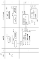
- FIG. 1 shows a configuration of a process management apparatus 10 using a process database 20 of the present embodiment.
- the process management apparatus 10 includes a model construction unit 11, a task construction unit 12, and an influence identification unit 13.
- the process database 20 is structured by storing software development process data in a storage device such as a disk.
- the storage device that stores the process database 20 includes a model storage unit 21 and a task storage unit 22.
- the model storage unit 21 stores a model 24 describing characteristics of software to be developed.
- the task storage unit 22 stores a task 27 that is a work item performed by a human to create the model 24. The model 24 and the task 27 will be described later.
- the object of development is not limited to software.
- the development object may be, for example, hardware such as devices and parts, and service specifications such as education.
- the development object will be described using software as an example.
- the model construction unit 11 is operated by a human to create a model 24 and store it in the model storage unit 21.
- the task construction unit 12 is operated by a human to create a task 27 and store it in the task storage unit 22.
- the influence identifying unit 13 is operated by a human and searches the process database 20.
- the model construction unit 11, the task construction unit 12, and the influence identification unit 13 are connected to a user terminal device (not shown) that includes a keyboard, a display, and the like.
- the model construction unit 11, the task construction unit 12, and the influence identification unit 13 are realized by hardware such as a logic circuit. They may be realized by software executed by the processor 16 of the process management apparatus 10.
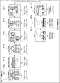
- FIG. 2 shows an example of the model 24 stored in the model storage unit 21.
- the model 24 is created in each step 23 of software development and stored in correspondence with the step 23.
- the model 24-3 is created in the requirement definition process and stored in correspondence with the process.
- the model 24-6 is created in the AP (Application Program) structural design process and stored in correspondence with the process.
- the model 24 is data describing a plurality of elements (this is called a development element 25) and the structure between the characteristics of the software to be developed. What the development element 25 corresponds to the software to be developed is determined depending on the process 23.
- the development element 25-1 of the model 24-1 in the target structuring process is the purpose of development software that is sequentially broken down.
- This model 24-1 has, for example, a tree structure.
- the development element 25-2 of the model 24-9 in the prototype creation process is a program code of each object.
- This model 24-9 has a group structure reflecting the class.
- the model 24 is created by the developer using, for example, a development editor tool.
- the used development editor tool is the model construction unit 11 in FIG.
- the development editor tool may be a different tool in each process of development, or may be the same tool in several processes.
- the development editor tool is, for example, a CASE (Computer Aided Software Engineering) tool that is generally widely used.
- the model construction unit 11 outputs the model 24 as an XML (Extended ⁇ ⁇ ⁇ ⁇ Markup Language) file, for example.
- FIG. 3 shows the model 24 output in the form of an XML file stored in the model storage unit 21 corresponding to each step of software development.
- the model storage unit 21 may store association 29 that is association information starting from the development element 25 of the model 24 of a certain process and starting from the development element 25 of the model 24 of the subsequent process.
- the association 29 indicates that, for example, when the starting development element 25 is changed or added, the end development element 25 is also changed or added.
- the relation 29-1 has a development element 25-1 of the target structuring process as a starting point and a development element 25-2 of the requirement defining process as an end point. This indicates, for example, that if there is a change in the software purpose b, the non-functional requirement b should be changed.
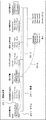
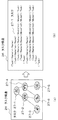
- FIG. 4 shows an example of the task 27 stored in the task storage unit 22.
- the task storage unit 22 corresponds to the development element 25 included in the model 24 of each process 23, and is necessary for the development element 25 in the process 23, that is, work necessary for realizing or completing the development element 25.
- the plurality of tasks 27 are stored as a task structure 26 including a structure description.
- the task storage unit 22 generally stores the task structure 26 corresponding to the development element 25.
- the structure is, for example, an execution order or a start condition.
- the task 27-3 is executed after the task 27-2 and the task 27-2 is executed after the task 27-1 is completed.
- task 27-6 indicates that both task 27-2 and task 27-4 are executed after completion.
- the structure of the task 27 may be a group structure that reflects a group of developers.
- the task structure 26 is created by the developer using, for example, a development editor tool.
- the used development editor tool is the task construction unit 12 of FIG.
- the development editor tool may be a different tool in each process of development, or may be the same tool in several processes. Further, the development editor tool may be the same as that used for creating the model 24 or may be different. If they are the same, the development editor tool is not only the task construction unit 12 but also the model construction unit 11.
- the task construction unit 12 outputs the model 24 as, for example, an XML file ((b) in FIG. 4).
- FIG. 5 shows a task structure 26 output in the form of an XML file stored in the task storage unit 22 corresponding to each step of software development.
- one task structure 26 is described corresponding to each step 23, but normally, a plurality of task structures 26 corresponding to a plurality of development items 25 of the model 24 in the step 23. Is stored.
- the task storage unit 22 may store a link 28 that is association information having a task 27 of a certain process 23 as a start point and a task 27 of a subsequent process 23 as an end point.
- the link 28 indicates, for example, that the end task 27 is redone when the result of the start task 27 changes, that is, the end task 27 is affected by the result of the start task 27.
- the link 28-1 has a task 27-1 of the target structuring process as a start point and a task 27-2 of the requirement definition process as an end point. This indicates that, for example, if the objective structuring work b is redone, the requirement definition work b should be redone.
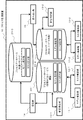
- FIG. 6 shows an example of the correspondence relationship between the data stored in the model storage unit 21 of the process database 20 and the data stored in the task storage unit 22.
- the model storage unit 21 stores the model 24 corresponding to the process 23.
- the model 24 of the n-th process has a tree structure in which the development element 25-1 is a parent and the development element 25-2 and the development element 25-3 are children.
- the model 24 of the (n + 1) th process has a sequence structure of a development element 25-4, a development element 25-5, and a development element 25-6.
- the relation 29-1 is extended from the development element 25-3 to the development element 25-5.
- n is any number from 1 to (number of steps 23-1).
- the model 24 includes attribute information corresponding to each development element 25.
- the attribute information is, for example, a work result of the task 27 performed for the development element 25 in the step 23.
- the task storage unit 22 stores a task structure 26 corresponding to the development element 25.
- a pointer to the task structure 26 is stored in the model storage unit 21 corresponding to the development element 25.
- the task structure 26-1 corresponds to the development element 25-2
- the task structure 26-2 corresponds to the development element 25-3
- the task structure 26-4 corresponds to the development element 25-4.
- a task structure 26-5 is stored corresponding to the development element 25-5
- a task structure 26-3 is stored corresponding to the development element 25-6. There is no task structure 26 corresponding to the development element 25-1.
- the task structure 26 indicates, for example, a start condition (execution order restriction) of the task 27.
- the task structure 26-1 includes three tasks 27 (27-1, 27-2, 27-3) executed in order by the developer. That is, the developer starts the subsequent task 27 after the task 27 in the previous order is completed.
- the task structure 26-2 includes two sets of two tasks 27 executed in sequence (a set of 27-4 and 27-5, and a set of 27-6 and 27-7). There is no restriction on the execution order between the two sets.
- the task structure 26-3 includes three tasks 27 (27-10, 27-11, 27-12) having a tree structure. In this case, the task 27-12 and the task 27-11 are started after the task 27-10 is finished, but there is no execution order restriction between the task 27-12 and the task 27-11.
- a link 28-1 is extended from task 27-2 to task 27-12. That is, the developer indicates that when the task 27-2 is re-executed, the task 27-12 is also re-executed.
- a link 28-2 and a link 28-3 are extended from the task 27-7 to the task 27-14 and the task 27-16, respectively. That is, when the developer re-executes task 27-7, it indicates that task 27-14 and task 27-16 should also be re-executed.
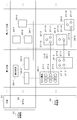
- FIG. 7 shows an example of specific data stored in the process database 20.
- FIG. 7 shows that “product search” (development element 25-3) is one of the requirement items to be defined by the developer in the requirement definition step.
- the developer clarifies the screen system, product code system, audit log content, required performance, etc. for “product search”, for example.
- the task 27 which is a work item performed by the developer includes, for example, “UI (User Interface) screen definition” (task 27-1), “input data definition” (task 27-2), and “audit log definition”. (Task 27-3) and “required performance definition” (task 27-4) exist.
- FIG. 7 shows a “sales subsystem” (development element 25-4) and “UI subsystem” (development) as subsystems to be designed by the developer in subsystem design, which is the next process of requirement definition. It indicates that there is an element 25-5) and a “DB (Database) management subsystem” (development element 25-6).
- the task 27 which is a work item performed by the developer includes, for example, “interactive function design” (task 27-5) and “DB interface design” (task 27-6). ) Exists. In FIG. 7, no special structure is defined between these tasks 27, and the task storage unit 22 simply stores a set of the above-described tasks 27 in association with the development element 25-5. Yes.
- the task 27 which is a work item performed by the developer is, for example, “schema design” (task 27-7), “input / output design” (task 27-8). "Performance design” (task 27-9) exists.
- the task storage unit 22 simply stores the set of tasks 27 described above in association with the development element 25-6. Yes.
- the task structure 26 or task 27 corresponding to the design of the “sales subsystem” is omitted.
- Link 28-4 and link 28-5 are, for example, when the developer redoes “audit log definition”, “UI interface” “DB interface design” and “DB management subsystem” “input / output method design”. Indicates that both must be redone. For example, when the developer redoes the “performance definition”, the link 28-6 and the link 28-7 must redo both the “input / output system design” and the “performance design” of the “DB management subsystem”. Indicates that it must not be.
- the model 24 includes attribute information corresponding to each development element 25.
- the model 24 of the request definition process 23 includes result information such as “UI screen definition” (task 27-1) as attribute information corresponding to “product search” (development element 25-3).
- the model 24 of the subsystem design process 23 corresponds to the “DB management subsystem” (development element 25-6), the result information such as “performance design” (task 27-9), and the attribute information.
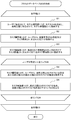
- FIG. 8 is an operation flowchart when the process management apparatus 10 creates the process database 20.
- This creation process includes execution of task 27 by a developer (also simply referred to as a user). Therefore, this creation process is not necessarily performed all at once, and may be performed over the entire period of software development and operation, including interruption and correction as needed.
- the process management apparatus 10 repeats the processing from S1 to S5 for all the steps 23 of software development.
- the model construction unit 11 creates a model 24 by being operated by the user, and stores it in the model storage unit 21 in association with the process.
- the model construction unit 11 is a development editor tool
- the user operates the tool from the user terminal and creates the model 24 while executing the work item of the process.
- the request definition step 23 the user uses the CASE tool for request definition to execute work items such as “UI screen definition”, “input data definition”, “Search” request definition is performed, and the result is created as a model 24.
- the model construction unit 11 stores one of the development elements 25 of the previous process 23 and any of the development elements 25 of the previous process 23 from the user, and stores the association 29 having the former as the start point and the latter as the end point. May be.
- the task construction unit 12 acquires the designation of the development element 25 and the task structure 26 or individual tasks 27 input by the user. That is, the user inputs the work items executed for the development element 25 in the process from the user terminal into the task construction unit 12 in a format that can be stored as the task structure 26 or the task 27.
- the task construction unit 12 stores the task structure 26 or the task 27 in the task storage unit 22 in association with the designated development element 25.
- the task construction unit 12 creates a link 28 specified by the user and stores it in the task storage unit 22. Therefore, the task construction unit 12 repeats steps S4 and S5 for each link 28.
- the task construction unit 12 acquires the designation of the task 27 in the process 23 and the designation of the task 27 in the process 23 before the process 23 from the user, and in S5, the task 27 in the previous process 23 is obtained. And a link 28 with the task 27 of the process 23 as the end point is set and stored in the task storage unit 22.
- the process database 20 created in this way can be used for various purposes. For example, in software agile development / repeated development, when the development loop returns, the development manager identifies the development element 25 whose specifications are to be changed, thereby affecting the affected process 23, component 25, task 27. Can be specified. With this information, the development manager can quantitatively estimate the impact.
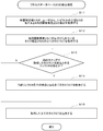
- FIG. 9 is an operation flowchart when the process management apparatus 10 searches the process database 20.
- the influence identifying unit 13 acquires designation of the development element 25 in the model 24 in any one of the steps 23 from the user.
- the user is a development manager, for example, and inputs designation of the development element 25 whose specification is changed from the user terminal.
- the influence identifying unit 13 acquires all the tasks 27 in the task structure 26 associated with the development element 25.
- the influence specifying unit 13 checks the presence or absence of the link 28 starting from the task 27 acquired in the previous step. When there is a link (Y in S13), the influence identifying unit 13 acquires all the tasks 27 that are the end points of the respective links 28 in S14. Thereafter, the influence identifying unit 13 returns to S13.
- the influence identifying unit 13 outputs all the acquired tasks 27.
- the influence identifying unit 13 may sequentially acquire and output the development element 25 that is the end point of the relation 29 by sequentially tracing the relation 29 starting from the designated development element 25 together with the search of the task 27. That is, the influence specifying unit 13 may search for the development element 25 that is affected by the specification of the designated development element 25.
- the influence specifying unit 13 may acquire not only the task 27 that is the end point of the link 28 but also the task 27 that is executed following the task 27 in the same task structure 26. The reason is that the task 27 executed following the task 27 executed again may be redone.
- the first effect of the process management apparatus 10 of the present embodiment is that the progress evaluation of the production process can be performed even in agile development or repetitive development.
- the process database 20 holds process data including the model 24, the task 27, and the link 28 in association with each step 23 such as from design to operation. Therefore, even if a user such as a development manager adds or changes a specification and starts the development cycle again, the progress of the development cycle can be evaluated by referring to the past process data corresponding to the changed part. it can.
- the process data may include the association 29.
- the second effect is that the overall cost required for development can be estimated. This makes it easier for the user to make an investment decision for developing a Web service or the like.
- the reason is that the process database 20 models and stores production processes including human activities based on process data in which the model 24 and the task 27 are linked.
- the task information indicating the activity of the human system has, as attributes, a time including adjustment time, buffer time, and the like, which are performed when resource competition such as a server used between developers' tasks occurs. That is, this task information includes data that is not included simply by accumulating man-hours for individual tasks. For this reason, the user can estimate quantitatively the range of the process 23 which the change specification gives, the range of the development element 25, and the influence of work man-hours using the data according to actual operation.
- the task 27 is a work item, that is, a data item describing the work content.
- the task 27 stores the role of the developer who should perform the task 27 and the work man-hour (for example, man month).
- a role is a classification of roles that each developer should play within the development organization. Roles include, for example, team leaders, architects, programmers, operators, and budget managers.
- the task 27 also has data indicating how much man-hours of the person in charge of which role is required for the work item correspondence.
- the task construction unit 12 sets the value by importing the work ticket man-hour information from, for example, a ticket issuance / management system widely used for development management such as Redmine.
- the influence identifying unit 13 outputs the task 27 including the roll and the work man-hour when the task 27 is output.
- the process database 20 of this embodiment makes it easier for the development manager to quantitatively estimate the impact when a specification change occurs.
- the reason is that the task 27 includes a roll and work man-hours.
- the process management apparatus 10 is used when different Web services are developed and executed using the same computer resources, such as PaaS (Platform as a Service) which is a cloud that provides a development / execution environment. Useful.
- the process management apparatus 10 according to the present embodiment includes a common repository so that a process database 20 of software developed in the past can be used as a development asset.
- FIG. 10 shows a configuration of the process management apparatus 10 according to the third embodiment.
- the process management apparatus 10 according to the present embodiment includes two types of the process database 20, the model construction unit 11, the task construction unit 12, and the influence identification unit 13 that are the same as those in the first embodiment.
- the first type (process database 20-1 or the like) is for initial WEB service development, and the other type (process database 20-2 or the like) is for another WEB service development. There may be a plurality of each type.
- the process management apparatus 10 further includes a third process database 20-3, a registration unit 14, and a reading unit 15.
- the third process database 20-3 is the aforementioned common repository.
- the user creates a process database 20-1 for a certain WEB service software using the initial WEB service development portion. Thereafter, the user uses the registration unit 14 to export and store the process data in the process database 20-1 in a common repository common to each development project.
- the user accumulates the process data in the development of a plurality of initial WEB services in the common repository.
- the process data can be reused as a development template for developing another Web service.
- the user uses the reading unit 15 to read the process data accumulated from the common repository and import it into the process database 20-2 for developing another WEB service.
- the user customizes the process data imported into the process database 20-2 as a template for the web service production process and proceeds with the development.
- the registration unit 14 copies the process data in the process database 20-1 designated by the user to the common repository.
- the reading unit 15 copies the process data of the common repository specified by the user to the process database 20-2 specified by the user.
- the development target is not limited to WEB service software.
- the process management apparatus 10 improves productivity. The reason is that the entire process of the entire development process is capitalized as process data and can be reused. This apparatus makes it easy for a user to develop new software by diverting / customizing assets such as past software. In particular, the user can easily estimate the total cost and determine the progress delay by referring to the task 27.
- the process management apparatus 10 of the present embodiment is useful when adding a new function or component.
- FIG. 11 shows a configuration of the process management apparatus 10 according to the fourth embodiment.
- the process management apparatus 10 according to the present embodiment includes a process database 20 and an influence specifying unit 13.
- the process database 20 in the present embodiment is a common repository in the third embodiment. That is, the process database 20 stores process data for a plurality of software developed in the past.
- the influence specifying unit 13 in the present embodiment acquires a model 24 for a function or part newly added to the software from the user, searches for a matching model 24 from the process database 20 by matching processing, and The development element 25 and the task 27 to be output are output.
- FIG. 12 is an operation flowchart of matching processing in the present embodiment.
- the influence specifying unit 13 acquires a model 24 to be matched from the user.
- the influence identifying unit 13 repeats the processing from S22 to S24 for all the software stored in the process database 20.
- the impact identification unit 13 outputs all the tasks 27 corresponding to each of the matching development elements 25 and the task 27 that is the end point of the link 28 starting from the task 27. This process is the same as S12 to S15 in FIG.
- the influence identifying unit 13 may sequentially acquire and output the development element 25 that is the end point of the relation 29 by sequentially tracing the relation 29 starting from the matching development element 25 in the same manner as the search of the task 27. . That is, the influence specifying unit 13 may search for the development element 25 that is affected by the specifications of the matching development element 25.
- the influence specifying unit 13 may acquire not only the task 27 that is the end point of the link 28 but also the task 27 that is executed following the task 27 in the same task structure 26.
- the process management apparatus 10 makes it easy to estimate the development work and cost performed by the user for functions and parts newly added to the software. The reason is that, from process data such as software developed in the past, a model 24 that at least partially matches the development target function or the like is searched, and the task 27 and development element 25 related to the development element 25 that matches. Is output.
- FIG. 13 shows the configuration of the process management apparatus 10 according to the fifth embodiment.
- the process database 20 includes a model storage unit 21 and a task storage unit 22.
- the model storage unit 21 stores a model 24 describing a plurality of development elements 25 in each step 23 of product development corresponding to the step 23.
- the task storage unit 22 stores a task 27 performed by a human in each process 23 in association with the development element 25 of the model 24 in the process 23.
- the task storage unit 22 further adds the task 27 of the first process 23 as the start point, the task 27 of the second process 23 that is the subsequent process 23 of the first process 23, and the result of the task 27 that is the start point.
- the process database 20 facilitates identification of work that occurs during development or when software or hardware that has already been developed is changed. The reason is that the process database 20 associates the model 24, the task 27, and the link 28 and holds them for each process 23 such as from design to operation. As a result, even when the specification is added / changed and the development cycle is started again, the user can easily manage the progress and estimate the cost.
- process database 20 improves the productivity of software and the like.
- the process database 20 capitalizes the entire process of the entire development process as process data and can be reused. This makes it easier for the user to divert past software assets.
Landscapes
- Engineering & Computer Science (AREA)
- General Engineering & Computer Science (AREA)
- Software Systems (AREA)
- Theoretical Computer Science (AREA)
- Physics & Mathematics (AREA)
- General Physics & Mathematics (AREA)
- Stored Programmes (AREA)
Description
本発明は、ソフトウェア等の開発プロセスのデータを格納あるいは検索するための、プロセスデータベース、プロセス管理装置、プロセスデータベース作成方法、プロセスデータベース検索方法、および、プログラムに関する。
ソフトウェアの開発プロセスの評価に関連して、以下の技術が知られている。
特許文献1は、プロジェクト完遂までに段階的に達成される小目標の系列をブレークダウンした情報と目標相互の影響関係を作成する、手戻りリスク評価システムを開示する。この手戻りリスク評価システムは、開発中にある目標が達成不可能となった場合に影響範囲(手戻り対象範囲)を特定する。
特許文献2は、システム構築の為の管理システムを開示する。このシステムは、構築されるシステムに含まれる構成要素に関連付けてタスクの一覧を表示する。また、このシステムは、タスクと他のタスクとの関連、例えば、単体テストの完了が総合テストの前提条件であることを表示する。
特許文献3は、過去の開発実績を基に開発工数の基準を作成し評価を行う、プロジェクト管理支援装置を開示する。この装置は、過去の複数の実績を統計処理し、評価対象のプロジェクトの計画値を比較し、プロジェクトが計画通り運営されていない場合にそのリスクを検出する。
特許文献4は、設計作業の履歴に関する情報を、テンプレートに関連づけて蓄積するシステムが開示されている。
開発中、または、開発済みのソフトウェア/ハードウェア等の開発対象物を変更する場合に、発生する作業、いわゆる修正作業の特定は容易ではない。
特許文献1に開示されているシステムは、特定した影響範囲を修正するための作業についての情報は何も提示しない。特許文献4に開示されているシステムも同様である。
特許文献2に記載されたシステムは、そもそも、ソフトウェアの開発の工程を管理対象にしていない。従って、当該システムは、開発済みのソフトウェアを変更する場合に、発生する作業についての情報は何も提示しない。特許文献3は、ソフトウェアの変更については直接関知しない。
本発明は、上記課題を解決するための構造化データを格納した、データベース等を提供することを目的とする。
本発明の一実施の形態のプロセスデータベースは、プロダクト開発の各工程における複数の開発要素を記述したモデルを、前記工程対応に格納するモデル保管手段と、前記工程において人間が行う作業項目を、当該工程の前記モデルの前記開発要素対応に格納するタスク保管手段と、を包含するデータベースであって、前記タスク保管手段は、さらに、第1の前記工程の前記作業項目を始点、前記第1の工程の後続工程である第2の前記工程の前記作業項目であって、前記始点である前記作業項目の結果に影響される前記作業項目を終点とするリンクを格納する。
本発明の一実施の形態のプロセスデータベース作成方法は、プロダクト開発の各工程における複数の開発要素を記述したモデルを、前記工程対応に記憶し、前記工程において人間が行う作業項目を、当該工程の前記モデルの前記開発要素対応に記憶し、さらに、第1の前記工程の前記作業項目を始点、前記第1の工程の後続工程である第2の前記工程の前記作業項目であって、前記始点である前記作業項目の結果に影響される前記作業項目を終点とするリンクを記憶する。
本発明の一実施の形態のプログラムは、プロダクト開発の各工程における複数の開発要素を記述したモデルを、前記工程対応に記憶手段に記憶する処理と、前記工程において人間が行う作業項目を、当該工程の前記モデルの前記開発要素対応に前記記憶手段に記憶する処理と、さらに、第1の前記工程の前記作業項目を始点、前記第1の工程の後続工程である第2の前記工程の前記作業項目であって、前記始点である前記作業項目の結果に影響される前記作業項目を終点とするリンクを前記記憶手段に記憶する処理と、をコンピュータに実行させる。
本発明に係るプロセスデータは、ソフトウェアと実行リソースと人間系のタスクを含む生産プロセス全体を資産化したものである。そのため、開発中、または、開発済みのソフトウェア/ハードウェア等を変更する場合に、タスクの情報から、発生する作業項目や量の特定を可能にする。
<第1の実施の形態>
図1は、本実施の形態のプロセスデータベース20を用いた、プロセス管理装置10の構成を示す。プロセス管理装置10は、プロセスデータベース20以外に、モデル構築部11、タスク構築部12、影響特定部13を包含する。
図1は、本実施の形態のプロセスデータベース20を用いた、プロセス管理装置10の構成を示す。プロセス管理装置10は、プロセスデータベース20以外に、モデル構築部11、タスク構築部12、影響特定部13を包含する。
プロセスデータベース20は、ソフトウェアの開発プロセスのデータを構造化して、ディスク等の記憶装置に格納したものである。プロセスデータベース20を格納する記憶装置は、モデル保管部21とタスク保管部22を含む。モデル保管部21は、開発されるソフトウェアの特性を記述したモデル24を格納する。タスク保管部22には、モデル24を作成するために人間が行う作業項目であるタスク27を格納する。モデル24やタスク27は後述する。
なお、開発の目的物はソフトウェアに限られない。開発の目的物は、例えば、装置、部品等のハードウェア、教育等のサービス仕様であっても良い。以降、開発の対象物はソフトウェアを例に説明する。
モデル構築部11は人間に操作されて、モデル24を作成して、モデル保管部21に格納する。タスク構築部12は人間に操作されて、タスク27を作成して、タスク保管部22に格納する。影響特定部13は、人間に操作されて、プロセスデータベース20の検索を行う。モデル構築部11、タスク構築部12、及び、影響特定部13は、キーボード、ディスプレイなどを備えたユーザ端末装置(図示されず)に接続している。
モデル構築部11、タスク構築部12、および、影響特定部13は、論理回路等のハードウェアで実現される。それらは、プロセス管理装置10のプロセッサ16で実行されるソフトウェアで実現されても良い。
<プロセスデータベース20が格納するデータ>
図2は、モデル保管部21に格納されるモデル24の例を示す。モデル24はソフトウェア開発の各工程23で作成され、当該工程23に対応して格納される。例えば、モデル24-3は要件定義工程で作成され、当該工程に対応して格納される。モデル24-6はAP(Application Program)の構造設計工程で作成され、当該工程に対応して格納される。
図2は、モデル保管部21に格納されるモデル24の例を示す。モデル24はソフトウェア開発の各工程23で作成され、当該工程23に対応して格納される。例えば、モデル24-3は要件定義工程で作成され、当該工程に対応して格納される。モデル24-6はAP(Application Program)の構造設計工程で作成され、当該工程に対応して格納される。
モデル24は、開発されるソフトウェアの特性を、複数の要素(これを開発要素25と呼ぶ)とその間の構造を記述したデータである。開発要素25が、開発対象ソフトウェアの何に相当するかは、工程23に依存して決まる。
例えば、図2に於いて、目的の構造化工程に於けるモデル24-1の開発要素25-1は、順次ブレークダウンされる開発ソフトウェアの目的である。このモデル24-1は、例えば、木構造を持つ。プロトタイプ作成工程に於けるモデル24-9の開発要素25-2は、各オブジェクトのプログラムコードである。このモデル24-9はクラスを反映したグループ構造を持つ。
なお、図中、同種の要素に対しては同じ番号を用いる、同種の要素が複数あるときは、枝番号(ハイフォン以降の数字)を用いる。枝番号は、一つの図の中でのみ一意である。
モデル24は、開発者が、例えば、開発エディタツール等を使用して作成する。この場合、使用された開発エディタツールが、図1のモデル構築部11である。開発エディタツールは、開発の各工程で異なったツールであっても良いし、いくつかの工程で同じツールであってもよい。開発エディタツールは、例えば、一般に広く使用されているCASE(Computer Aided Software Engineering)ツールである。
モデル構築部11は、モデル24を、例えば、XML(Extended Markup Language)のファイルとして出力する。図3は、モデル保管部21にソフトウェア開発の各工程に対応して格納された、XMLファイルの形式で出力されたモデル24を示す。
モデル保管部21は、ある工程のモデル24の開発要素25を始点、後続する工程のモデル24の開発要素25を終点とする関連づけ情報である関連29を格納していても良い。関連29は、例えば、始点の開発要素25が変更または追加されたとき、終点の開発要素25も変更または追加されることを示す。
図3において、関連29-1は、目的の構造化工程の開発要素25-1を始点、要件定義工程の開発要素25-2を終点とする。これは、例えば、ソフトウェアの目的 bに変更があれば、非機能要件 bを変更すべきであることを示す。
図4の(a)は、タスク保管部22に格納されるタスク27の例を示す。タスク保管部22は、各工程23のモデル24に含まれる開発要素25対応に、その工程23で、その開発要素25について必要となる、即ち、その開発要素25の実現あるいは完成に必要となる作業項目、即ち、作業内容を記述したデータ項目であるタスク27の集合を格納する。
多くの場合、開発要素25の完成に必要となる複数のタスク27は構造を持つため、複数のタスク27は構造記述を含むタスク構造26として格納される。換言すれば、タスク保管部22は、一般に、開発要素25対応にタスク構造26を格納する。
構造は、例えば、実行順序または開始条件である。例えば、図4のタスク構造26においては、タスク27-3はタスク27-2が、タスク27-2はタスク27-1が完了してから実行されることを示す。同様に、タスク27-6は、タスク27-2とタスク27-4の両者が完了してから実行されることを示す。タスク27の構造は、開発者のグループを反映したグループ構造であっても良い。
タスク構造26は、開発者が、例えば、開発エディタツール等を使用して作成する。この場合、使用された開発エディタツールが、図1のタスク構築部12である。開発エディタツールは、開発の各工程で異なったツールであっても良いし、いくつかの工程で同じツールであってもよい。また、開発エディタツールは、モデル24の作成に使われたものと、同じものであっても良いし、異なったものであってもよい。同じものである場合、その開発エディタツールはタスク構築部12であると同時に、モデル構築部11でもある。
タスク構築部12は、モデル24を、例えば、XMLのファイルとして出力する(図4の(b))。図5は、タスク保管部22にソフトウェア開発の各工程に対応して格納された、XMLファイルの形式で出力されたタスク構造26を示す。ここでは、簡単のため、各工程23対応に一つのタスク構造26を記載しているが、通常、当該工程23に於けるモデル24の複数の開発項目25に対応して、複数のタスク構造26が格納される。
タスク保管部22は、ある工程23のタスク27を始点、後続する工程23のタスク27を終点とする関連づけ情報であるリンク28を格納していても良い。リンク28は、例えば、始点のタスク27の結果が変わると終点のタスク27をやり直す、即ち、終点のタスク27は始点のタスク27の結果に影響されることを示す。
図5において、リンク28-1は、目的の構造化工程のタスク27-1を始点、要件定義工程のタスク27-2を終点とする。これは、例えば、目的構造化作業 bをやり直すと、要件定義作業 bをやり直すべきであることを示す。
図6は、プロセスデータベース20のモデル保管部21に格納されるデータとタスク保管部22に格納されるデータとの対応関係の例を示す。モデル保管部21は、工程23対応にモデル24を格納する。図6において、第n工程のモデル24は、開発要素25-1を親、開発要素25-2及び開発要素25-3を子とする木構造を持つ。第n+1工程のモデル24は、開発要素25-4、開発要素25-5及び開発要素25-6のシーケンス構造を持つ。関連29-1が、開発要素25-3から開発要素25-5に張られている。ここで、nは、1乃至(工程23の数-1)の何れかの数である。
なお、図6に於いて明示されていないが、モデル24は、各開発要素25に対応して、属性情報を包含する。属性情報は、例えば、当該工程23で当該開発要素25について実施されたタスク27の作業結果である。
タスク保管部22は、開発要素25に対応してタスク構造26を格納する。一般的には、モデル保存部21内に、開発要素25対応にタスク構造26へのポインタを格納する。図6において、開発要素25-2に対応してタスク構造26-1が、開発要素25-3に対応してタスク構造26-2が、開発要素25-4に対応してタスク構造26-4が、開発要素25-5に対応してタスク構造26-5が、開発要素25-6に対応してタスク構造26-3が格納されている。開発要素25-1に対応するタスク構造26は存在しない。
図6において、タスク構造26は、例えば、タスク27の開始条件(実行順序の制約)を示す。タスク構造26-1は、開発者が順番に実行する3つのタスク27(27-1、27-2、27-3)を包含する。即ち、開発者は、順番の前のタスク27が終了してから、後続のタスク27を開始する。タスク構造26-2は、順番に実行される2つのタスク27の2の組(27-4及び27-5の組、並びに、27-6及び27-7の組)を包含する。当該2つの組の間には、実行順序の制約は無い。タスク構造26-3は、木構造を持つ3つのタスク27(27-10、27-11、27-12)を包含する。この場合、タスク27-12及びタスク27-11はタスク27-10が終了してから開始されるが、タスク27-12及びタスク27-11の間に実行順序の制約はない。
図6において、タスク27-2からタスク27-12にはリンク28-1が張られている。即ち、開発者は、タスク27-2を実行し直すと、タスク27-12も実行し直すべきことを示す。また、タスク27-7からタスク27-14およびタスク27-16の2つにはおのおのリンク28-2およびリンク28-3が張られている。即ち、開発者は、タスク27-7を実行し直すと、タスク27-14及びタスク27-16も実行し直すべきことを示す。
図7は、プロセスデータベース20に格納される具体的データの例を示す。図7は、要求定義工程に於いて、開発者が定義すべき要求項目の一つとして、”商品検索”(開発要素25-3)があることを示す。
本工程に於いて開発者は、例えば、”商品検索”について、画面体系、商品コードの体系、監査ログ内容、要求性能等を明確にする。この為に開発者が行う作業項目であるタスク27は、例えば、”UI(User Interface)画面定義”(タスク27-1)、”入力データ定義”(タスク27-2)、”監査ログ定義”(タスク27-3)、”要求性能定義”(タスク27-4)が存在する。
図7の例に於いて、タスク27間に特別な構造は定義されておらず、タスク保管部22は、単に上述のタスク27の集合を、開発要素25-3に対応付けて記憶している。
さらに、図7は、要求定義の次工程であるサブシステム設計に於いて、開発者が設計すべきサブシステムとして、”販売サブシステム”(開発要素25-4)、”UIサブシステム”(開発要素25-5)及び”DB(Database)管理サブシステム”(開発要素25-6)があることを示す。
この工程の”UIサブシステム”の設計に於いて、開発者が行う作業項目であるタスク27は、例えば、”対話機能設計”(タスク27-5)と”DBインターフェース設計”(タスク27-6)が存在する。図7に於いて、これらのタスク27間にも特別な構造は定義されておらず、タスク保管部22は、単に上述のタスク27の集合を、開発要素25-5に対応付けて記憶している。
さらに、”DB管理サブシステム”の設計に於いて、開発者が行う作業項目であるタスク27は、例えば、”スキーマ設計”(タスク27-7)、”入出力設計”(タスク27-8)、”性能設計”(タスク27-9)が存在する。図7に於いて、これらのタスク27間にも特別な構造は定義されておらず、タスク保管部22は、単に上述のタスク27の集合を、開発要素25-6に対応付けて記憶している。本図に於いて、”販売サブシステム”の設計に対応するタスク構造26またはタスク27は省略されている。
”UI画面定義”から”対話機能設計”へ、”入力データ定義”から”対話機能設計”、”入力データ定義”から”DBインターフェース設計”へ、 ”監査ログ定義”から”DBインターフェース設計”へ、”監査ログ定義”から”入出力方式設計”へ、”性能定義”から入”出力方式設計”へ、”性能定義”から”性能設計”へ、おのおのリンク28(順次、リンク28-1乃至7)が張られている。リンク28-4とリンク28-5は、例えば、開発者が”監査ログ定義”をやり直すと、”UIサブシステム”の”DBインターフェース設計”および”DB管理サブシステム”の”入出力方式設計”の両者をやり直さなければならないことを示している。また、リンク28-6とリンク28-7は、例えば、開発者が”性能定義”をやり直すと、”DB管理サブシステム”の”入出力方式設計”と”性能設計”の両者をやり直さなければならないことを示している。
なお、図7に於いて明示されていないが、モデル24は、各開発要素25に対応して、属性情報を包含する。例えば、要求定義の工程23のモデル24は、”商品検索”(開発要素25-3)に対応して、”UI画面定義”(タスク27-1)等の結果情報を属性情報として包含する。同様に、サブシステム設計の工程23のモデル24は、”DB管理サブシステム”(開発要素25-6)に対応して、”性能設計”(タスク27-9)等の結果情報を、属性情報として包含する。
<プロセス管理装置10の動作>
図8は、プロセス管理装置10がプロセスデータベース20を作成するときの動作フローチャートである。この作成過程は、開発者(単にユーザともいう)によるタスク27の実行を含む。従って、この作成過程は、必ずしも一時期に一括して行われるものではなく、随時、中断、修正を含みながら、ソフトウェアの開発・運用の全期間にわたって行われてもよい。
図8は、プロセス管理装置10がプロセスデータベース20を作成するときの動作フローチャートである。この作成過程は、開発者(単にユーザともいう)によるタスク27の実行を含む。従って、この作成過程は、必ずしも一時期に一括して行われるものではなく、随時、中断、修正を含みながら、ソフトウェアの開発・運用の全期間にわたって行われてもよい。
プロセス管理装置10は、ソフトウェア開発の全ての工程23について、S1からS5の処理を繰り返す。まずS1に於いて、ユーザに操作されて、モデル構築部11がモデル24を作成し、当該工程に対応付けて、モデル保管部21に格納する。例えば、モデル構築部11が開発エディタツールである場合、ユーザはユーザ端末から当該ツールを操作して、当該工程の作業項目を実行しながらモデル24を作成する。図7の例に於いて、要求定義の工程23で、ユーザは要求定義用のCASEツールを使用して、”UI画面定義”、”入力データ定義”等の作業項目を実行しながら、”商品検索”の要求定義を実施し、その結果をモデル24として作成する。
このとき、モデル構築部11は、ユーザから前の工程23の開発要素25の何れか及び当該工程の開発要素25のいずれかを指定されて、前者を始点、後者を終点とする関連29を記憶してもよい。
次に、S2において、タスク構築部12が、ユーザが入力した、開発要素25の指定及びタスク構造26あるいは個々のタスク27を取得する。即ち、ユーザは、ユーザ端末から、当該工程で当該開発要素25について実行した作業項目をタスク構造26あるいはタスク27として格納できる形式で、タスク構築部12に入力する。
S3において、タスク構築部12は、指定された開発要素25に対応付けて、タスク構造26あるいはタスク27をタスク保管部22に格納する。
次に、タスク構築部12は、ユーザから指定されるリンク28を張って、タスク保管部22に格納する。このため、タスク構築部12は、リンク28ごとにS4とS5のステップを繰り返す。
S4において、タスク構築部12は、ユーザから、当該工程23のタスク27の指定、及び、当該工程23の前の工程23のタスク27の指定を取得し、S5において、前の工程23のタスク27を始点、当該工程23のタスク27を終点とするリンク28を張って、タスク保管部22に格納する。
このように作成されたプロセスデータベース20は、様々な用途に使用できる。例えばソフトウェアのアジャイル開発・繰り返し開発等に於いて、開発ループが戻るときに、開発管理者は、仕様変更を行う開発要素25を特定することで、影響を受ける工程23、構成要素25、タスク27を特定することが出来る。この情報により、開発管理者は、影響を定量的に見積ることができる。
図9は、プロセス管理装置10がプロセスデータベース20を検索するときの動作フローチャートである。
まず、S11において、影響特定部13が、ユーザから、いずれかの工程23のモデル24内の開発要素25の指定を取得する。ここでユーザは、例えば、開発管理者であり、仕様変更が行われる開発要素25の指定をユーザ端末から入力する。次に、S12に於いて、影響特定部13は、当該開発要素25に対応付けられているタスク構造26内の全てのタスク27を取得する。
S13において、影響特定部13は、前のステップで取得したタスク27を始点とするリンク28の有無をチェックする。リンクがある場合(S13でY)、影響特定部13は、S14において当該リンク28各々の終点となる全てのタスク27を取得する。その後、影響特定部13は、S13に戻る。
S13でリンクがない場合(S13でN)、影響特定部13は、取得した全てのタスク27を出力する。
影響特定部13は、タスク27の検索と共に、指定された開発要素25を始点とする関連29を順次たどって、関連29の終点である開発要素25を順次取得し、出力しても良い。即ち、影響特定部13は、指定された開発要素25の仕様の影響を受ける開発要素25の検索を行っても良い。
さらに、影響特定部13は、S14に於いて、リンク28の終点となるタスク27のみならず、同一タスク構造26内で当該タスク27に後続して実行されるタスク27も取得しても良い。その理由は、再度実行されるタスク27に続いて実行されるタスク27もやり直しの可能性が有るからである。
本実施形態のプロセス管理装置10の第1の効果は、アジャイル開発や繰り返し開発においても、生産プロセスの進捗評価を行えることである。その理由は、プロセスデータベース20が、モデル24、タスク27及びリンク28を関連付けて包含するプロセスデータを、設計から運用まで等の各工程23対応に保持するからである。そのため、開発管理者等のユーザは、仕様の追加・変更を行い再び開発サイクルを回す場合においても、変更部分に対応する、過去のプロセスデータを参照することで、当該開発サイクルの進捗状況を評価できる。なお、ここで、プロセスデータが、関連29を含むことがあるのは前述の通りである。
第2の効果は、開発に要する全体コストの見積りを行えることである。そのため、ユーザは、Webサービス等の開発の投資判断が容易になる。その理由は、プロセスデータベース20が、モデル24とタスク27を紐づけたプロセスデータにより人間系の活動を含めた生産プロセスをモデル化して格納しているためである。この人間系の活動を示すタスク情報は、開発者のタスク間で使用サーバなどのリソース競合が起きた場合に行われる調整時間や、バッファ時間などが包含された時間を属性に持つ。即ち、このタスク情報は、単に個々のタスクに対する工数の積み上げでは含まれないデータを包含する。このため、ユーザは、変更仕様が与える工程23の範囲、開発要素25の範囲、作業工数の影響を、実運用に則したデータを用いて、定量的に見積ることができる。
<第2の実施の形態>
第1の実施形態に於いて、タスク27は、作業項目、即ち、作業内容を記述したデータ項目である。本実施の形態に於いては、タスク27は、それにくわえて、当該タスク27を実施すべき開発者のロールと作業工数(例えば、人月)を格納する。
第1の実施形態に於いて、タスク27は、作業項目、即ち、作業内容を記述したデータ項目である。本実施の形態に於いては、タスク27は、それにくわえて、当該タスク27を実施すべき開発者のロールと作業工数(例えば、人月)を格納する。
ここで、ロールとは、開発組織内で各開発者が果たすべき役割の分類である。ロールには、例えば、チームリーダ、アーキテクト、プログラマ、オペレータ、予算管理者がある。
本実施の形態に於いて、タスク27は、作業項目対応に、どのロールの担当者の作業工数がどの程度必要になるかのデータも併せ持つ。
タスク構築部12は、この値を、例えば、Redmine等開発管理用に広く用いられるチケット発行・管理システムから、作業チケットの工数情報をインポートして設定する。
本実施形態に於いて、影響特定部13は、タスク27を出力する際に、ロールや作業工数を含めて出力する。
本実施形態のプロセスデータベース20は、仕様変更の発生時に、開発管理者が影響を定量的に見積ることを更に容易にする。その理由は、タスク27にロールと作業工数を包含するからである。
<第3の実施形態>
本実施形態のプロセス管理装置10は、例えば、開発・実行環境を提供するクラウドであるPaaS(Platform as a Service)のように、異なるWebサービスが同じ計算機資源を用いて開発および実行される場合に有用である。本実施形態のプロセス管理装置10は、過去に開発したソフトウェアのプロセスデータベース20を開発資産として利用できるようにするため、共通リポジトリを備える。
本実施形態のプロセス管理装置10は、例えば、開発・実行環境を提供するクラウドであるPaaS(Platform as a Service)のように、異なるWebサービスが同じ計算機資源を用いて開発および実行される場合に有用である。本実施形態のプロセス管理装置10は、過去に開発したソフトウェアのプロセスデータベース20を開発資産として利用できるようにするため、共通リポジトリを備える。
図10は、第3の実施の形態のプロセス管理装置10の構成を示す。本実施の形態のプロセス管理装置10は、第1の実施の形態と同じプロセスデータベース20、モデル構築部11、タスク構築部12、影響特定部13を2種類備える。第1の種類(プロセスデータベース20-1等)は初期WEBサービス開発用であり、他の種類(プロセスデータベース20-2等)は別WEBサービス開発用である。各種類は各々複数存在しても良い。
本実施の形態のプロセス管理装置10は、さらに、第3のプロセスデータベース20-3、登録部14、及び、読み出し部15を備える。第3のプロセスデータベース20-3が前述の共通リポジトリである。
本実施の形態に於いては、まず、ユーザは、初期WEBサービス開発用の部分を用いて、あるWEBサービス用ソフトウェアのプロセスデータベース20-1を作成する。その後、ユーザは登録部14を用いて、プロセスデータベース20-1内のプロセスデータを各開発プロジェクト共通の共通リポジトリにエクスポートして保管する。
このようにして、ユーザは、複数の初期WEBサービス開発に於けるプロセスデータを、共通リポジトリに蓄積する。これにより、当該プロセスデータは、別のWebサービス開発の開発テンプレートとして再利用できる。
新規にWebサービスを開発する場合、ユーザは、読み出し部15を用いて、共通リポジトリから蓄積されていたプロセスデータを読み出して、別WEBサービス開発用のプロセスデータベース20-2にインポートする。ユーザは、新たなWebサービスの開発を進める際には、プロセスデータベース20-2にインポートしたプロセスデータを当該Webサービス生産プロセスのテンプレートとし、カスタマイズして開発を進める。
本実施形態に於いて、登録部14は、ユーザに指定されたプロセスデータベース20-1のプロセスデータを、共通リポジトリにコピーする。読み出し部15は、共通リポジトリのプロセスデータであってユーザに指定されたものを、ユーザに指定されたプロセスデータベース20-2にコピーする。
なお、開発対象は、WEBサービス用ソフトウェアに限られない。
本実施の形態のプロセス管理装置10は、生産性を向上させる。その理由は、開発全行程のプロセス全体をプロセスデータとして資産化しており、再利用出来るからある。本装置は、ユーザが、過去のソフトウェア等の資産を流用・カスタマイズして、新たなソフトウェアを開発することを容易にする。特に、ユーザは、タスク27を参照することで、全体コストの見積りや、進捗遅延の判断が容易になる。
<第4の実施形態>
本実施の形態のプロセス管理装置10は、新たな機能や部品を追加する場合に有用である。
本実施の形態のプロセス管理装置10は、新たな機能や部品を追加する場合に有用である。
図11は、第4の実施の形態のプロセス管理装置10の構成を示す。本実施の形態のプロセス管理装置10は、プロセスデータベース20と影響特定部13を備える。本実施の形態に於けるプロセスデータベース20は、第3の実施形態における共通リポジトリである。即ち、このプロセスデータベース20は、過去に開発した複数のソフトウェアについてのプロセスデータを格納する。
本実施の形態に於ける影響特定部13は、ユーザから新たにソフトウェアに追加する機能や部品についてのモデル24を取得して、プロセスデータベース20内から一致するモデル24をマッチング処理で検索し、関連する開発要素25やタスク27を出力する。
図12は、本実施の形態に於けるマッチング処理の動作フローチャートである。まず、S21において、影響特定部13は、ユーザからマッチング対象となるモデル24を取得する。次に、影響特定部13は、プロセスデータベース20に格納されている全ソフトウェアを対象に、S22からS24の処理を繰り返す。
S22において、モデル保管部21に格納されている当該ソフトウェアのモデル24の中に、少なくともその一部がマッチング対象のモデル24と一致するものがあるかチェックする。
ある場合(S23でY)、S24において、影響特定部13は、一致する開発要素25のおのおのに対応するタスク27、及び、それを始点とするリンク28の終点となるタスク27を全て出力する。この処理は、図9のS12乃至S15と同じ処理である。
無い場合(S23でN)は、次のソフトウェアのプロセスデータを探索する。
影響特定部13は、タスク27の検索と共に、同様にして一致する開発要素25を始点とする関連29を順次たどって、関連29の終点である開発要素25を順次取得し、出力しても良い。即ち、影響特定部13は、一致する開発要素25の仕様の影響を受ける開発要素25の検索を行っても良い。
影響特定部13は、S24で、リンク28の終点となるタスク27のみならず、同一タスク構造26内で当該タスク27に後続して実行されるタスク27も取得しても良い。
本実施の形態のプロセス管理装置10は、ソフトウェアに新たに追加する機能や、部品について、ユーザが行う開発作業見積もりやコスト見積もりをし易くする。その理由は、過去に開発したソフトウェア等のプロセスデータから、開発対象機能等と、少なくともその一部が一致するモデル24を検索し、一致する開発要素25に関連しているタスク27、開発要素25を出力するからである。
<第5の実施形態>
図13は、第5の実施の形態のプロセス管理装置10の構成を示す。
図13は、第5の実施の形態のプロセス管理装置10の構成を示す。
プロセスデータベース20は、モデル保管部21と、タスク保管部22を包含する。モデル保管部21は、プロダクト開発の各工程23における複数の開発要素25を記述したモデル24を、工程23対応に格納する。
タスク保管部22は、各工程23において人間が行うタスク27を、当該工程23のモデル24の開発要素25に対応させて格納する。タスク保管部22は、さらに、第1の工程23のタスク27を始点、第1の工程23の後続工程23である第2の工程23のタスク27であって、始点であるタスク27の結果に影響されるタスク27を終点とするリンク28を格納する。
本実施の形態にかかるプロセスデータベース20は、開発中、または、開発済みのソフトウェア/ハードウェア等を変更する場合に、発生する作業の特定を容易にする。その理由は、プロセスデータベース20が、モデル24、タスク27、リンク28を関連付けて、設計から運用まで等の各工程23対応に保持するからである。その結果、仕様の追加・変更を行い再び開発サイクルを回す場合においても、ユーザは、進捗管理やコストの見積もりが容易になる。
さらに、本実施の形態にかかるプロセスデータベース20は、ソフトウェア等の生産性を向上させる。その理由は、プロセスデータベース20が、開発全行程のプロセス全体をプロセスデータとして資産化しており、再利用出来るからある。これにより、ユーザが、過去のソフトウェア資産を流用し易くなる。
以上、実施形態を参照して本願発明を説明したが、本願発明は上記実施形態に限定されものではない。本願発明の構成や詳細には、本願発明のスコープ内で当業者が理解し得る様々な変更をすることができる。
この出願は、2012年9月18日に出願された日本出願特願2012-204426を基礎とする優先権を主張し、その開示の全てをここに取り込む。
10 プロセス管理装置
11 モデル構築部
12 タスク構築部
13 影響特定部
14 登録部
15 読み出し部
16 プロセッサ
20 プロセスデータベース
21 モデル保管部
22 タスク保管部
23 工程
24 モデル
25 開発要素
26 タスク構造
27 タスク
28 リンク
29 関連
11 モデル構築部
12 タスク構築部
13 影響特定部
14 登録部
15 読み出し部
16 プロセッサ
20 プロセスデータベース
21 モデル保管部
22 タスク保管部
23 工程
24 モデル
25 開発要素
26 タスク構造
27 タスク
28 リンク
29 関連
Claims (10)
- プロダクト開発の各工程における複数の開発要素を記述したモデルを、前記工程対応に格納するモデル保管手段と、
前記工程において人間が行う作業項目を、当該工程の前記モデルの前記開発要素対応に格納するタスク保管手段と、を包含し、
前記タスク保管手段は、さらに、第1の前記工程の前記作業項目を始点、前記第1の工程の後続工程である第2の前記工程の前記作業項目であって、前記始点である前記作業項目の結果に影響される前記作業項目を終点とするリンクを格納するプロセスデータベース。 - 請求項1に記載のプロセスデータベースと、
何れかの前記工程の前記モデルの前記開発要素の指定を取得して、前記タスク保管手段から指定された前記開発要素に対応する前記作業項目を取得し、さらに、取得した前記作業項目を始点とする前記リンクの終点である前記作業項目を取得し、取得した前記作業項目を出力する影響特定手段と、を備えるプロセス管理装置。 - 前記モデルは、さらに、第3の前記工程の前記開発要素を始点、前記第3の工程の後続工程である第4の前記工程の前記開発要素であって、前記始点である前記開発要素の変更に影響される前記開発要素を終点とする関連付けを格納し、
前記影響特定手段は、指定された前記開発要素を始点とする前記関連付けの終点である前記開発要素を取得し、取得した前記開発要素を出力する、請求項2のプロセス管理装置 - 複数のプロダクトの各々に対応して、前記モデルと前記作業項目を格納する請求項1のプロセスデータベースと、
前記複数のプロダクトとは異なるプロダクトの前記モデルである別モデルを取得して、前記モデル保管手段内の前記モデルである格納モデルと当該別モデルを比較して、少なくとも一部が当該別モデルと一致する前記格納モデルを特定し、特定された前記格納モデル内のうち当該別モデルと一致する前記開発要素に対応する前記作業項目を取得し、さらに、取得した前記作業項目を始点とする前記リンクの終点である前記作業項目を取得し、取得した前記作業項目を出力する影響特定手段と、を備えるプロセス管理装置。 - 前記タスク保管手段は、前記作業項目の各々に対応して、当該作業項目の作業者のロールおよび工数を格納し、
前記影響特定手段は、さらに、取得した前記作業項目に対応する前記ロール及び前記工数を取得して出力する、請求項2乃至4の何れかに記載のプロセス管理装置。 - 請求項1に記載のプロセスデータベースと、
何れかの前記工程で前記モデルを作成して、当該工程対応に作成した当該モデルを前記モデル手段に格納するモデル構築手段と、
何れかの前記工程の前記モデルの前記開発要素の指定、及び、前記作業項目を入力して、当該作業項目を、指定された前記開発要素に対応付けて前記タスク保管手段に格納し、さらに、指定された工程の前の前記工程の前記作業項目、および、指定された前記工程の前記作業項目の指定を取得して、両者間に前記リンクを設定するタスク構築手段と、を備えるプロセス管理装置。 - プロダクト開発の各工程における複数の開発要素を記述したモデルを、前記工程対応に記憶し、
前記工程において人間が行う作業項目を、当該工程の前記モデルの前記開発要素対応に記憶し、
さらに、第1の前記工程の前記作業項目を始点、前記第1の工程の後続工程である第2の前記工程の前記作業項目であって、前記始点である前記作業項目の結果に影響される前記作業項目を終点とするリンクを記憶するプロセスデータベース作成方法。 - 何れかの前記工程の前記モデルの前記開発要素の指定を取得して、前記タスク保管手段から指定された前記開発要素に対応する前記作業項目を取得し、さらに、取得した前記作業項目を始点とする前記リンクの終点である前記作業項目を取得し、取得した前記作業項目を出力する、請求項1に記載のプロセスデータベースの検索方法。
- プロダクト開発の各工程における複数の開発要素を記述したモデルを、前記工程対応に記憶手段に記憶する処理と、
前記工程において人間が行う作業項目を、当該工程の前記モデルの前記開発要素対応に前記記憶手段に記憶する処理と、
さらに、第1の前記工程の前記作業項目を始点、前記第1の工程の後続工程である第2の前記工程の前記作業項目であって、前記始点である前記作業項目の結果に影響される前記作業項目を終点とするリンクを前記記憶手段に記憶する処理と、をコンピュータに実行させるプログラム。 - 請求項1に記載のプロセスデータベースを備えたコンピュータに、何れかの前記工程の前記モデルの前記開発要素の指定を取得して、前記タスク保管手段から指定された前記開発要素に対応する前記作業項目を取得し、さらに、取得した前記作業項目を始点とする前記リンクの終点である前記作業項目を取得し、取得した前記作業項目を出力する処理を実行させるプログラム。
Priority Applications (1)
| Application Number | Priority Date | Filing Date | Title |
|---|---|---|---|
| JP2014536585A JPWO2014045554A1 (ja) | 2012-09-18 | 2013-09-13 | プロセスデータベース、プロセス管理装置、プロセスデータベース作成方法、プロセスデータベース検索方法、および、プログラム |
Applications Claiming Priority (2)
| Application Number | Priority Date | Filing Date | Title |
|---|---|---|---|
| JP2012-204426 | 2012-09-18 | ||
| JP2012204426 | 2012-09-18 |
Publications (1)
| Publication Number | Publication Date |
|---|---|
| WO2014045554A1 true WO2014045554A1 (ja) | 2014-03-27 |
Family
ID=50340896
Family Applications (1)
| Application Number | Title | Priority Date | Filing Date |
|---|---|---|---|
| PCT/JP2013/005436 Ceased WO2014045554A1 (ja) | 2012-09-18 | 2013-09-13 | プロセスデータベース、プロセス管理装置、プロセスデータベース作成方法、プロセスデータベース検索方法、および、プログラム |
Country Status (2)
| Country | Link |
|---|---|
| JP (1) | JPWO2014045554A1 (ja) |
| WO (1) | WO2014045554A1 (ja) |
Cited By (1)
| Publication number | Priority date | Publication date | Assignee | Title |
|---|---|---|---|---|
| WO2023084791A1 (ja) * | 2021-11-15 | 2023-05-19 | 日本電気株式会社 | 情報管理装置、システム及び方法、並びに、コンピュータ可読媒体 |
Citations (6)
| Publication number | Priority date | Publication date | Assignee | Title |
|---|---|---|---|---|
| JPH0756720A (ja) * | 1993-08-16 | 1995-03-03 | Toshiba Corp | 成果物間の整合性を維持するソフトウェア開発成果物管理方法および装置 |
| JP2003140894A (ja) * | 2001-11-05 | 2003-05-16 | Hitachi Ltd | ソフトウェア開発資源間の関連付け方法及びそのプログラム |
| JP2004355326A (ja) * | 2003-05-29 | 2004-12-16 | Incs Inc | ソフトウェア開発支援プログラム、当該プログラムを記録した記録媒体及びソフトウェア開発支援システム |
| JP2009037294A (ja) * | 2007-07-31 | 2009-02-19 | Nippon Telegr & Teleph Corp <Ntt> | ソフトウェア成果物管理システム、方法及びそのプログラム |
| JP2009053951A (ja) * | 2007-08-27 | 2009-03-12 | Toshiba Corp | ソフトウェア開発情報管理装置及びプログラム |
| JP2009176010A (ja) * | 2008-01-24 | 2009-08-06 | Internatl Business Mach Corp <Ibm> | 工程管理を行うシステム、工程管理方法およびプログラム |
-
2013
- 2013-09-13 JP JP2014536585A patent/JPWO2014045554A1/ja active Pending
- 2013-09-13 WO PCT/JP2013/005436 patent/WO2014045554A1/ja not_active Ceased
Patent Citations (6)
| Publication number | Priority date | Publication date | Assignee | Title |
|---|---|---|---|---|
| JPH0756720A (ja) * | 1993-08-16 | 1995-03-03 | Toshiba Corp | 成果物間の整合性を維持するソフトウェア開発成果物管理方法および装置 |
| JP2003140894A (ja) * | 2001-11-05 | 2003-05-16 | Hitachi Ltd | ソフトウェア開発資源間の関連付け方法及びそのプログラム |
| JP2004355326A (ja) * | 2003-05-29 | 2004-12-16 | Incs Inc | ソフトウェア開発支援プログラム、当該プログラムを記録した記録媒体及びソフトウェア開発支援システム |
| JP2009037294A (ja) * | 2007-07-31 | 2009-02-19 | Nippon Telegr & Teleph Corp <Ntt> | ソフトウェア成果物管理システム、方法及びそのプログラム |
| JP2009053951A (ja) * | 2007-08-27 | 2009-03-12 | Toshiba Corp | ソフトウェア開発情報管理装置及びプログラム |
| JP2009176010A (ja) * | 2008-01-24 | 2009-08-06 | Internatl Business Mach Corp <Ibm> | 工程管理を行うシステム、工程管理方法およびプログラム |
Cited By (3)
| Publication number | Priority date | Publication date | Assignee | Title |
|---|---|---|---|---|
| WO2023084791A1 (ja) * | 2021-11-15 | 2023-05-19 | 日本電気株式会社 | 情報管理装置、システム及び方法、並びに、コンピュータ可読媒体 |
| JPWO2023084791A1 (ja) * | 2021-11-15 | 2023-05-19 | ||
| JP7794481B2 (ja) | 2021-11-15 | 2026-01-06 | 日本電気株式会社 | 情報管理装置、システム及び方法、並びに、プログラム |
Also Published As
| Publication number | Publication date |
|---|---|
| JPWO2014045554A1 (ja) | 2016-08-18 |
Similar Documents
| Publication | Publication Date | Title |
|---|---|---|
| EP3072079B1 (en) | A system and method for implementing application policies among development environments | |
| US9760077B2 (en) | Content management | |
| US9459846B2 (en) | User interface style guide compliance | |
| CN102736915B (zh) | 自动程序生成装置、方法以及计算机程序 | |
| US9563861B2 (en) | Integration of workflow and library modules | |
| US20170235661A1 (en) | Integration of Software Systems via Incremental Verification | |
| US20120254832A1 (en) | Expression editor system | |
| Kargar et al. | Automation of regression test in microservice architecture | |
| US11611627B2 (en) | Action flow fragment management | |
| US9135000B2 (en) | Runtime process diagnostics | |
| US12265949B2 (en) | Dynamically controlling case model structure using case fragments | |
| US12554862B2 (en) | Integrated security analysis data structure and method for multi-container software projects | |
| US20050125769A1 (en) | Software development | |
| US20250306860A1 (en) | Validating code ownership of software components in a software development system | |
| Bernardi et al. | Model-driven fast prototyping of RIAs: From conceptual models to running applications | |
| WO2014045554A1 (ja) | プロセスデータベース、プロセス管理装置、プロセスデータベース作成方法、プロセスデータベース検索方法、および、プログラム | |
| Assiri et al. | Software quality in the era of big data, iot and smart cities | |
| US9405514B1 (en) | Process fragment management | |
| Bousetta et al. | Automating software development process: Analysis-PIMs to Design-PIM model transformation | |
| US20030028396A1 (en) | Method and system for modelling an instance-neutral process step based on attribute categories | |
| Maikantis et al. | SmartCLIDE: Shortening the toolchain of SOA-based cloud software development by automating service creation, composition, testing, and deployment | |
| Randhawa | Software Life Cycle | |
| Urbieta et al. | Identifying and modelling complex workflow requirements in web applications | |
| Jirapanthong | Requirements traceability on web applications | |
| Jackson | The Structure of Automation |
Legal Events
| Date | Code | Title | Description |
|---|---|---|---|
| 121 | Ep: the epo has been informed by wipo that ep was designated in this application |
Ref document number: 13838717 Country of ref document: EP Kind code of ref document: A1 |
|
| ENP | Entry into the national phase |
Ref document number: 2014536585 Country of ref document: JP Kind code of ref document: A |
|
| NENP | Non-entry into the national phase |
Ref country code: DE |
|
| 122 | Ep: pct application non-entry in european phase |
Ref document number: 13838717 Country of ref document: EP Kind code of ref document: A1 |