WO2014041631A1 - 鉄骨のウエブ開口補強構造 - Google Patents
鉄骨のウエブ開口補強構造 Download PDFInfo
- Publication number
- WO2014041631A1 WO2014041631A1 PCT/JP2012/073310 JP2012073310W WO2014041631A1 WO 2014041631 A1 WO2014041631 A1 WO 2014041631A1 JP 2012073310 W JP2012073310 W JP 2012073310W WO 2014041631 A1 WO2014041631 A1 WO 2014041631A1
- Authority
- WO
- WIPO (PCT)
- Prior art keywords
- web
- opening
- steel
- auxiliary
- steel frame
- Prior art date
- Legal status (The legal status is an assumption and is not a legal conclusion. Google has not performed a legal analysis and makes no representation as to the accuracy of the status listed.)
- Ceased
Links
Images



Classifications
-
- E—FIXED CONSTRUCTIONS
- E04—BUILDING
- E04C—STRUCTURAL ELEMENTS; BUILDING MATERIALS
- E04C3/00—Structural elongated elements designed for load-supporting
- E04C3/02—Joists; Girders, trusses, or trusslike structures, e.g. prefabricated; Lintels; Transoms; Braces
- E04C3/04—Joists; Girders, trusses, or trusslike structures, e.g. prefabricated; Lintels; Transoms; Braces of metal
- E04C3/08—Joists; Girders, trusses, or trusslike structures, e.g. prefabricated; Lintels; Transoms; Braces of metal with apertured web, e.g. with a web consisting of bar-like components; Honeycomb girders
-
- E—FIXED CONSTRUCTIONS
- E04—BUILDING
- E04C—STRUCTURAL ELEMENTS; BUILDING MATERIALS
- E04C3/00—Structural elongated elements designed for load-supporting
- E04C3/02—Joists; Girders, trusses, or trusslike structures, e.g. prefabricated; Lintels; Transoms; Braces
- E04C3/04—Joists; Girders, trusses, or trusslike structures, e.g. prefabricated; Lintels; Transoms; Braces of metal
- E04C3/08—Joists; Girders, trusses, or trusslike structures, e.g. prefabricated; Lintels; Transoms; Braces of metal with apertured web, e.g. with a web consisting of bar-like components; Honeycomb girders
- E04C3/09—Joists; Girders, trusses, or trusslike structures, e.g. prefabricated; Lintels; Transoms; Braces of metal with apertured web, e.g. with a web consisting of bar-like components; Honeycomb girders at least partly of bent or otherwise deformed strip- or sheet-like material
Definitions
- the present invention relates to a web opening reinforcing structure for reinforcing an opening formed in a steel web having an H-shaped cross section.
- the steel frame is configured to have an I-type or H-type cross-section by a central web and flanges at both ends of the web.
- piping for air-conditioning equipment and electrical equipment is arranged in buildings.
- the equipment piping is disposed so as to avoid the steel frame, it is necessary to increase the width between the upper floor and the lower floor, that is, the height of the floor, and the construction cost is increased accordingly. Therefore, in recent years, it has become common to provide an opening for equipment piping in the web for the purpose of reducing the floor height.
- Patent Document 1 Conventionally, as this type of technology, there is a technology described in Patent Document 1. According to Patent Document 1, a through hole for equipment piping is opened in a beam joint portion, and the deterioration of beam performance due to this is caused by a flange splice plate having a predetermined thickness and an angle disposed on the beam web while avoiding the opening. A technique of reinforcing with a splice material made of a splice plate has been proposed.
- the floor height increases by the height from the opening to the flange in the web. If the height of the web and the size of the opening can be made the same, the floor height can be reduced.
- An object of the present invention is to provide a web opening reinforcing structure that makes it possible to enlarge an opening through which equipment piping passes without changing the height of a steel frame web.
- the present invention has the following configuration in order to achieve the above-mentioned object.
- a steel frame that includes a pair of flanges and a web that connects the pair of flanges, and that reinforces the vicinity of an opening for facility piping formed in the web, in which the web is arranged along the vertical direction.
- the auxiliary web is arranged at a predetermined distance from the opening in the width direction of the steel frame, the strength against the shear stress in the vicinity of the opening in the steel frame is improved. For this reason, even if the height of the web, that is, the length between the pair of flanges, and the size of the opening are set to be the same, the strength against the shearing stress is ensured. Accordingly, it is not necessary to set the web height long in order to form the opening, so that the floor height can be reduced. Further, a facility piping path is formed which enters between one auxiliary web and the web and passes through the opening and exits between the other auxiliary web and the web. For this reason, it is possible to easily pass the equipment piping through the steel frame.
- the plurality of auxiliary webs are arranged in parallel to the web, and when the steel frame is viewed from the width direction, the auxiliary web is a rectangle that covers the entire opening. Structure for reinforcing steel web openings
- the auxiliary web functions in the same manner as the web, the strength in the vicinity of the opening of the web, which has been reduced by forming the opening, can be reliably compensated by the auxiliary web.
- the plurality of auxiliary webs are arranged symmetrically with respect to the web.
- the steel frame is made of H steel, and the auxiliary web is made of I steel, and is welded between the pair of flanges. Construction.
- the auxiliary web is provided on both sides of the opening, the strength against shear stress in the vicinity of the opening in the web is improved. For this reason, even if the height of the web and the size of the opening are set to be the same, the strength against shearing stress is ensured, and the floor height can be suppressed.
- FIG. 1 It is a perspective view which shows the principal part of the web opening reinforcement structure of the steel frame 1 in one Embodiment of this invention. It is AA sectional drawing of FIG. It is BB sectional drawing of FIG. It is CC sectional drawing of FIG. It is explanatory drawing which shows the structure which passed the equipment piping through the steel frame 1 in one Embodiment of this invention. It is explanatory drawing which shows the structure which passed the equipment piping through the steel frame 1 in one Embodiment of this invention. It is a perspective view which shows the principal part of the modification of the web opening reinforcement structure of the steel frame 1 in one Embodiment of this invention.
- FIG. 1 is a perspective view showing a main part of a web opening reinforcing structure for a steel frame 1 according to an embodiment of the present invention.
- 2 is a cross-sectional view taken along the line AA in FIG.
- FIG. 3 is a BB cross-sectional view of FIG.
- FIG. 4 is a cross-sectional view taken along CC of FIG.
- the web opening reinforcing structure of the present embodiment includes a steel frame 1 having an opening for equipment piping, and auxiliary webs 16 and 18.
- the steel frame 1 includes a web 10 and an upper flange 12 and a lower flange 14 corresponding to a pair of flanges.
- the X direction shown in FIG. 1 is referred to as a longitudinal direction
- the Y direction is referred to as a height direction
- the Z direction is referred to as a width direction.
- the longitudinal direction, the height direction, and the width direction are perpendicular to each other, and when the steel frame 1 provided with the auxiliary webs 16 and 18 is used as a beam of a building, the height direction is a vertical direction.
- the web 10, the upper flange 12, and the lower flange 14 are formed in a rectangular plate shape extending in the longitudinal direction.
- the upper flange 12 and the lower flange 14 are arranged to face each other with a predetermined distance.
- the web 10 connects the center portions of the upper flange 12 and the lower flange 14 in the width direction.
- the upper flange 12 is connected to the upper end portion of the web 10 and is connected to the lower end portion of the web 10. Therefore, the upper flange 12 and the lower flange 14 are arranged in the horizontal direction, and the web 10 is arranged in the vertical direction.
- the web 10 and the upper flange 14 are arranged as shown in FIG. It is visually recognized as an H shape by the flange 12 and the lower flange 14.
- the web 10 is formed with an opening 20 through which equipment piping is passed.
- the opening 20 has a rectangular shape, and the length of the opening 20 in the height direction is equal to the length of the web 10 in the height direction.
- the opening 20 is formed between the surfaces of the upper flange 12 and the lower flange 14 facing each other, and the web 10 is discontinuous at the opening 20 portion.
- the auxiliary webs 16 and 18 are arranged at a predetermined distance from the opening 20 in the width direction of the steel frame 1, and are rectangular plate-like members that connect the upper flange 12 and the lower flange 14. It is.
- the auxiliary webs 16 and 18 face each other through the opening 20.
- the length and thickness of the auxiliary webs 16 and 18 in the height direction are the same as those of the web 10, and the length of the auxiliary webs 16 and 18 in the longitudinal direction is set to be greater than or equal to the length of the opening 20 in the longitudinal direction. .
- it is desirable that the length of the auxiliary webs 16 and 18 in the longitudinal direction is substantially equal to or slightly longer than the length of the opening 20 in the longitudinal direction.
- the auxiliary webs 16 and 18 are viewed in the width direction (Z direction view), the opening 20 is completely covered by the auxiliary webs 16 and 18.
- the total thickness of the auxiliary webs 16 and 18 is preferably equal to or greater than the thickness of the web 10.
- auxiliary webs 16 and 18 are arranged at an equal distance in the width direction with respect to the web 10 as shown in FIGS. That is, the auxiliary webs 16 and 18 are arranged symmetrically with respect to the web 10. For this reason, a gap 22 is formed between the auxiliary web 16 and the web 10, and a gap 24 is formed between the auxiliary web 18 and the web 10.
- the lengths of the gap 22 and the gap 24 in the width direction are the same length, and this length is set to a length that allows the equipment piping to pass through.
- Equipment piping refers to piping for air conditioning equipment, piping for passing various cables for electrical equipment, and the cable itself.
- FIG. 5 and 6 are explanatory views showing a structure in which the equipment pipe 100 is passed through the steel frame 1.
- the facility piping 100 is passed through the steel frame 1 by a route that enters the gap 22, passes through the opening 20, and exits from the gap 24.
- FIG. 5 there are a path that passes between the auxiliary webs 16 and 18 in a diagonal direction, and a path that passes in a U shape as shown in FIG. 6.
- the auxiliary webs 16 and 18 are arranged at a predetermined distance from the opening 20 in the width direction of the steel frame 1. Strength against shear stress is improved. For this reason, even if the length in the height direction of the web 10 and the length in the height direction of the opening 20 are set to be the same, the strength against shearing stress is ensured, and the height direction of the web 10 is formed when the opening 20 is formed. It is possible to make the whole as an opening without leaving a part. Thereby, it is not necessary to increase the height of the web in order to form the opening, and the height of the web can be shortened. As a result, the floor height of the building can be kept low, and the construction cost can be reduced.
- a path of equipment piping is formed such that it enters from the gap 22 between the one auxiliary web 16 and the web 10, passes through the opening 20 and exits from the gap 24 between the other auxiliary web 18 and the web 10. For this reason, it is possible to easily pass the equipment piping through the steel frame 1.
- the plurality of auxiliary webs 16 and 18 are arranged in parallel to the web 10, and the auxiliary webs 16 and 18 cover the entire opening 20 when the steel frame 1 is viewed from the width direction. ing. Accordingly, the strength of the web 10 that has decreased due to the formation of the opening 20 in the web 10 can be reliably compensated by the auxiliary webs 16 and 18.
- the center of rigidity of the auxiliary webs 16 and 18 can be positioned in the opening 20. For this reason, it becomes possible to obtain rigidity equal to or higher than that when the opening 20 is not formed in the web 10.
- the gap 22 between the auxiliary web 16 and the web 10 may be designed so that the gap 24 between the auxiliary web 18 and the web 10 located in the diagonal direction can be seen through the opening 20. Thereby, it becomes possible to take out the equipment pipe 100 from the gap 24 of the equipment pipe 100 by inserting the equipment pipe 100 into the gap 22 in the diagonal direction, and the work of inserting the equipment pipe 100 into the opening 20 of the steel frame 1 becomes easy.
- the auxiliary web 16 may be made of I steel, and the auxiliary web 16 made of I steel may be welded between the upper flange 12 and the lower flange 14. Thereby, for example, it becomes possible to form the auxiliary web 16 by cutting the existing I steel into the length of the opening 20 in the longitudinal direction and welding the I steel between the pair of flanges. If there is a gap between the auxiliary web 16 and the upper flange 12 or the lower flange 14, a steel plate may be interposed in the gap, and the auxiliary web 16 may be fixed between the pair of flanges together with the steel plate. .
Landscapes
- Engineering & Computer Science (AREA)
- Architecture (AREA)
- Civil Engineering (AREA)
- Structural Engineering (AREA)
- Rod-Shaped Construction Members (AREA)
Description
本発明は、H型断面を持つ鉄骨のウエブに形成された開口を補強するウエブ開口補強構造に関する。
従来より、I形、H型断面を持つ鉄骨による鉄骨造の建築物が多く見られる。ここで、鉄骨は、中央のウエブと、このウエブの両端のフランジとによって断面形状がI型あるいはH型になるように構成されている。ところで、建築物においては空調設備や電気設備用の配管が配設されている。ここで、設備配管を、鉄骨を避けるように配設すると、階上と階下との幅すなわち階高を大きくする必要があり、その分建築コストがかかる。そこで、近年、階高の低減を目的として、ウエブに設備配管の開口を設けることが一般的となっている。
しかし、ウエブに開口を設けることは、開口部分において剪断応力に対する強度が低下する。そこで、従来、開口部分を補強するための技術が提案されている。
従来、この種の技術としては、特許文献1に記載された技術がある。この特許文献1によれば、梁ジョイント部に設備配管用の貫通孔を開口し、これによる梁性能の低下は、所定厚のフランジスプライスプレート並びに開口を避けて梁ウエブに配されたアングル等のスプライスプレートからなるスプライス材により補強する、という技術が提案されている。
従来のウエブの開口を補強する方法としては、特許文献1に記載されているように、ウエブにおける開口周りに補強部材を接合させることが一般に行われている。しかし、この場合、開口部分における剪断応力に対する強度を確保するため、ウエブにおいて開口からフランジとの間にウエブの一部を残す必要がある。すなわち、ウエブの高さを開口の大きさより大きく設定する必要がある。
この場合、ウエブにおける開口からフランジまでの高さ分だけ階高が大きくなる。仮に、ウエブの高さと開口の大きさとを同じすることが可能であれば、階高を低減することが可能である。しかし、従来、開口からフランジまでの間にウエブの一部を残さずに、開口周辺を補強することが困難である。このため、鉄骨のウエブの高さを変えることなく設備配管が通る開口を大きくすることを可能にするウエブ開口補強構造の出現が望まれている。
本発明は、鉄骨のウエブの高さを変えることなく設備配管が通る開口を大きくすることを可能にするウエブ開口補強構造を提供することを目的とする。
本発明は、前記目的を達成するため、次に記載する構成を備えている。
(1) 一対のフランジと、当該一対のフランジを連結するウエブとを備え、当該ウエブが鉛直方向に沿って配置される鉄骨における、前記ウエブに形成された設備配管用の開口付近を補強する鉄骨のウエブ開口補強構造であって、前記開口から前記鉄骨の幅方向に所定の距離をおいて配置され、前記一対のフランジ間を連結する複数の補助ウエブを更に備えたことを特徴とする鉄骨のウエブ開口補強構造。
(1)によれば、開口から鉄骨の幅方向に所定の距離をおいて補助ウエブが配置されたことにより、鉄骨における開口付近の剪断応力に対する強度が向上する。このため、ウエブの高さすなわち一対のフランジ間の長さと、開口の大きさとを同じに設定しても、剪断応力に対する強度が確保されるようになる。これにより、開口を形成するためにウエブの高さを長く設定する必要がなくなるため、階高を低減することが可能になる。更に、一方の補助ウエブとウエブの間から入り、開口を通って他方の補助ウエブとウエブの間から出るという設備配管の経路が形成される。このため、鉄骨に設備配管を通すことが容易に可能になる。
(2) (1)において、前記複数の補助ウエブは、前記ウエブに対して平行に配置され、前記鉄骨を幅方向から視認した場合に、前記補助ウエブが前記開口の全体を覆う矩形であることを特徴とする鉄骨のウエブ開口補強構造
(2)によれば、補助ウエブがウエブと同等に機能することにより、開口を形成したことによって低下したウエブの開口付近の強度を、補助ウエブによって確実に補うことが可能になる。
(3) (1)、(2)において、前記複数の補助ウエブは、前記ウエブに対して線対称に配置されることを特徴とする鉄骨のウエブ開口補強構造。
(3)によれば、複数の補助ウエブを設けたことによる剛性の中心を、開口部分に位置付けることが可能になる。これにより、ウエブに開口を形成しなかった場合と同等、又はそれ以上の剛性を得ることが可能になる。
(4) (1)~(3)において、前記鉄骨は、H鋼からなり、前記補助ウエブは、I鋼からなり、前記一対のフランジ間に溶接されることを特徴とする鉄骨のウエブ開口補強構造。
(4)によれば、H鋼からなる鉄骨に形成されている開口の両側部に、I鋼を一対のフランジ間に溶接することによって、容易に補助ウエブを形成することが可能になる。
本発明によれば、開口の両側部に補助ウエブを備えたことにより、ウエブにおける開口付近の剪断応力に対する強度が向上する。このため、ウエブの高さと開口の大きさとを同じに設定しても剪断応力に対する強度が確保されるようになり、階高を押さえることが可能になる。
以下、本発明の実施形態について、図面を参照しながら詳細に説明する。
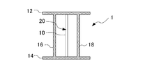
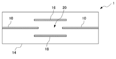
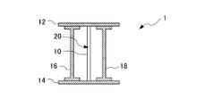
図1は、本発明の一実施形態における鉄骨1のウエブ開口補強構造の要部を示す斜視図である。図2は、図1のAA断面図である。図3は、図1のBB断面図である。図4は図1のCC断面図である。
図1は、本発明の一実施形態における鉄骨1のウエブ開口補強構造の要部を示す斜視図である。図2は、図1のAA断面図である。図3は、図1のBB断面図である。図4は図1のCC断面図である。
図1に示すように、本実施形態のウエブ開口補強構造は、設備配管用の開口を備えた鉄骨1と、補助ウエブ16、18とを備えている。
鉄骨1は、ウエブ10と、一対のフランジに相当する上フランジ12及び下フランジ14とを備えている。ここで、以下の説明の便宜上、図1に示すX方向を長手方向、Y方向を高さ方向、Z方向を幅方向と称することにする。また、長手方向、高さ方向及び幅方向は、それぞれ互いに垂直であり、補助ウエブ16、18を備えた鉄骨1を建築物の梁として用いた場合に、高さ方向が鉛直方向となる。
ウエブ10、上フランジ12及び下フランジ14は、長手方向に延びる矩形の板状に形成されている。上フランジ12及び下フランジ14は、所定の距離をおいて互いに対向配置されている。
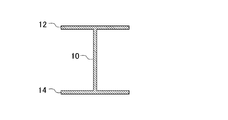
ウエブ10は、上フランジ12及び下フランジ14の幅方向における中央部を連結するものであり、ウエブ10の上端部に上フランジ12が連結され、ウエブ10の下端部に連結される。このため、上フランジ12及び下フランジ14は水平方向に、ウエブ10は鉛直方向に配置されており、鉄骨1を長手方向に沿って正面視した場合、図2に示すように、ウエブ10、上フランジ12及び下フランジ14によってH型に視認される。
また、ウエブ10には、設備配管を通すための開口20が形成されている。この開口20は矩形形状であり、開口20の高さ方向の長さは、ウエブ10の高さ方向の長さに等しい。言い換えれば、開口20は、上フランジ12と下フランジ14とにおける互いに対向する面の間に形成されており、ウエブ10は開口20の部分において不連続である。
また、図1に示すように、補助ウエブ16、18は、開口20から鉄骨1の幅方向に所定の距離をおいて配置され、上フランジ12と下フランジ14とを連結する矩形の板状部材である。補助ウエブ16、18は、開口20を介して互いに対向している。補助ウエブ16、18の高さ方向の長さ及び厚さはウエブ10と同一であり、補助ウエブ16、18の長手方向の長さは、開口20の長手方向の長さ以上に設定されている。ここで、補助ウエブ16、18の長手方向の長さは、開口20の長手方向の長さに略等しいか若干長いことが望ましい。このため、補助ウエブ16、18を幅方向視(Z方向視)した場合に、開口20は、補助ウエブ16、18によって完全に覆われる。なお、補助ウエブ16、18の厚さの合計が、ウエブ10の厚さ以上であることが望ましい。
更に、補助ウエブ16、18は、図3、図4に示すように、ウエブ10に対して幅方向に等距離に配置されている。すなわち、補助ウエブ16、18は、ウエブ10に対して線対称に配置されている。このため、補助ウエブ16とウエブ10との間には、隙間22が形成され、補助ウエブ18とウエブ10との間には、隙間24が形成される。隙間22及び隙間24の幅方向の長さは同じ長さであり、この長さは、設備配管を通すことが可能な長さに設定されている。
なお、設備配管とは、空調設備用の配管や、電気設備用の各種のケーブルを通すための配管、更にはケーブル自体等を指す。
図5及び図6は、鉄骨1に設備配管100を通した構造を示す説明図である。設備配管100は、隙間22に進入し、開口20を通って、隙間24から出るという経路で、鉄骨1に通される。設備配管100を通す経路としては、図5に示すように、補助ウエブ16、18の間を対角線方向に通る経路と、図6に示すように、U字型に通る経路がある。
以上、説明したように構成された本実施形態によれば、開口20から鉄骨1の幅方向に所定の距離をおいて補助ウエブ16、18が配置されたことにより、鉄骨1における開口20付近の剪断応力に対する強度が向上する。このため、ウエブ10の高さ方向の長さと開口20の高さ方向の長さとを同じに設定しても剪断応力に対する強度が確保され、開口20を形成する際に、ウエブ10の高さ方向に一部を残すことなく全体を開口とすることが可能になる。これにより、開口を形成するためにウエブの高さを高くする必要がなくなり、ウエブの高さを短くすることが可能になる。その結果、建築物の階高を低く抑えることが可能になり、建築コストを低減させることが可能になる。更に、一方の補助ウエブ16とウエブ10の隙間22から入り、開口20を通って他方の補助ウエブ18とウエブ10の隙間24から出るという設備配管の経路が形成される。このため、鉄骨1に設備配管を通すことが容易に可能になる。
また本実施形態によれば、複数の補助ウエブ16、18は、ウエブ10に対して平行に配置され、鉄骨1を幅方向から視認した場合に、補助ウエブ16、18が開口20の全体を覆っている。これにより、ウエブ10において開口20を形成したことによって低下したウエブ10の強度を、補助ウエブ16、18によって確実に補うことが可能になる。
また本実施形態によれば、補助ウエブ16、18による剛性の中心を開口20に位置付けることが可能になる。このため、ウエブ10に開口20を形成しなかった場合と同等、又はそれ以上の剛性を得ることが可能になる。
以上、本発明の実施形態について説明したが、本発明は、上述した実施形態に限るものではない。例えば、補助ウエブ16とウエブ10との隙間22から、開口20を介して対角線方向に位置する補助ウエブ18とウエブ10との隙間24が見えるように設計してもよい。これにより、設備配管100を隙間22に、対角線方向に挿入することによって設備配管100の隙間24から出すことが可能になり、設備配管100を鉄骨1の開口20に挿入する作業が容易になる。
また、図7に示すように、補助ウエブ16をI鋼によって構成し、上フランジ12と下フランジ14との間に、I鋼からなる補助ウエブ16を溶接してもよい。これにより、例えば、既存のI鋼を開口20の長手方向の長さに切断して、このI鋼を一対のフランジ間に溶接することによって、補助ウエブ16を形成することが可能になる。なお、補助ウエブ16と上フランジ12又は下フランジ14との間に隙間がある場合、その隙間に鋼板プレートを介在させて、この鋼板プレートとともに補助ウエブ16を一対のフランジ間に固定してもよい。
1 鉄骨
10 ウエブ
12 上フランジ
14 下フランジ
16、18 補助ウエブ
20 開口
22、24 隙間
100 設備配管
10 ウエブ
12 上フランジ
14 下フランジ
16、18 補助ウエブ
20 開口
22、24 隙間
100 設備配管
Claims (4)
- 一対のフランジと、当該一対のフランジを連結するウエブとを備え、当該ウエブが鉛直方向に沿って配置される鉄骨における、前記ウエブに形成された設備配管用の開口付近を補強する鉄骨のウエブ開口補強構造であって、
前記開口から前記鉄骨の幅方向に所定の距離をおいて配置され、前記一対のフランジ間を連結する複数の補助ウエブを更に備えたことを特徴とする鉄骨のウエブ開口補強構造。 - 前記複数の補助ウエブは、前記ウエブに対して平行に配置され、前記鉄骨を幅方向から視認した場合に、前記補助ウエブが前記開口の全体を覆う矩形であることを特徴とする請求項1記載の鉄骨のウエブ開口補強構造。
- 前記複数の補助ウエブは、前記ウエブに対して線対称に配置されることを特徴とする請求項1又は2記載の鉄骨のウエブ開口補強構造。
- 前記鉄骨は、H鋼からなり、
前記補助ウエブは、I鋼からなり、前記一対のフランジ間に溶接されることを特徴とする請求項1乃至3のいずれか1項記載の鉄骨のウエブ開口補強構造。
Priority Applications (2)
| Application Number | Priority Date | Filing Date | Title |
|---|---|---|---|
| JP2013513452A JP5274734B1 (ja) | 2012-09-12 | 2012-09-12 | 鉄骨のウエブ開口補強構造 |
| PCT/JP2012/073310 WO2014041631A1 (ja) | 2012-09-12 | 2012-09-12 | 鉄骨のウエブ開口補強構造 |
Applications Claiming Priority (1)
| Application Number | Priority Date | Filing Date | Title |
|---|---|---|---|
| PCT/JP2012/073310 WO2014041631A1 (ja) | 2012-09-12 | 2012-09-12 | 鉄骨のウエブ開口補強構造 |
Publications (1)
| Publication Number | Publication Date |
|---|---|
| WO2014041631A1 true WO2014041631A1 (ja) | 2014-03-20 |
Family
ID=49179235
Family Applications (1)
| Application Number | Title | Priority Date | Filing Date |
|---|---|---|---|
| PCT/JP2012/073310 Ceased WO2014041631A1 (ja) | 2012-09-12 | 2012-09-12 | 鉄骨のウエブ開口補強構造 |
Country Status (2)
| Country | Link |
|---|---|
| JP (1) | JP5274734B1 (ja) |
| WO (1) | WO2014041631A1 (ja) |
Cited By (1)
| Publication number | Priority date | Publication date | Assignee | Title |
|---|---|---|---|---|
| JP2022030382A (ja) * | 2020-08-07 | 2022-02-18 | Jfeスチール株式会社 | 鉄骨梁、柱梁接合構造およびこれを有する構造物 |
Citations (2)
| Publication number | Priority date | Publication date | Assignee | Title |
|---|---|---|---|---|
| JP2010261266A (ja) * | 2009-05-11 | 2010-11-18 | Panahome Corp | 梁の接合構造 |
| JP2011518265A (ja) * | 2008-04-11 | 2011-06-23 | キューエルディ スティール プロプライエタリー リミテッド | 建築構造部品およびその製造方法 |
-
2012
- 2012-09-12 WO PCT/JP2012/073310 patent/WO2014041631A1/ja not_active Ceased
- 2012-09-12 JP JP2013513452A patent/JP5274734B1/ja not_active Expired - Fee Related
Patent Citations (2)
| Publication number | Priority date | Publication date | Assignee | Title |
|---|---|---|---|---|
| JP2011518265A (ja) * | 2008-04-11 | 2011-06-23 | キューエルディ スティール プロプライエタリー リミテッド | 建築構造部品およびその製造方法 |
| JP2010261266A (ja) * | 2009-05-11 | 2010-11-18 | Panahome Corp | 梁の接合構造 |
Cited By (2)
| Publication number | Priority date | Publication date | Assignee | Title |
|---|---|---|---|---|
| JP2022030382A (ja) * | 2020-08-07 | 2022-02-18 | Jfeスチール株式会社 | 鉄骨梁、柱梁接合構造およびこれを有する構造物 |
| JP7351271B2 (ja) | 2020-08-07 | 2023-09-27 | Jfeスチール株式会社 | 鉄骨梁、柱梁接合構造およびこれを有する構造物 |
Also Published As
| Publication number | Publication date |
|---|---|
| JP5274734B1 (ja) | 2013-08-28 |
| JPWO2014041631A1 (ja) | 2016-08-12 |
Similar Documents
| Publication | Publication Date | Title |
|---|---|---|
| US7703244B2 (en) | Joint structure using a gusset plate, a building using the joint structure and a method of assembling or reinforcing a building | |
| KR101904958B1 (ko) | 철골보 강접합 구조 | |
| US9751539B2 (en) | Side bodyshell of railcar | |
| KR20170005392A (ko) | 개선된 강도를 가지는 모놀리스형 보를 사용하는 구조적 시스템 및 방법 | |
| KR20160123688A (ko) | 확대 헤드가 형성된 분기형 정착철근을 이용한 병렬 전단벽 연결보 보강 구조 | |
| JP6261976B2 (ja) | 変断面梁 | |
| JP6340181B2 (ja) | 鉄骨有孔部材の補強構造 | |
| JP7070890B2 (ja) | 仕口部構造 | |
| JP5635734B2 (ja) | 柱梁接合部および柱梁接合部の補強金物 | |
| JP5274734B1 (ja) | 鉄骨のウエブ開口補強構造 | |
| JP2017166122A (ja) | 鉄骨梁および柱梁接合構造 | |
| JP6809039B2 (ja) | 鋼製部材 | |
| JP5274735B1 (ja) | 鉄骨の開口補強構造 | |
| JP6769549B2 (ja) | 小梁接合方法、小梁接合構造、及び、支持部材 | |
| JP4802024B2 (ja) | トラス用t字形断面部材又は十字形断面部材の座屈補剛構造 | |
| JP2009221755A (ja) | 建物 | |
| KR101953015B1 (ko) | 철골건물 내진성능향상을 위한 가새 보강부재 및 이를 이용한 가새의 무용접/비좌굴 보강방법 | |
| KR20210079526A (ko) | 합성기둥 및, 합성기둥과 보부재의 접합구조 | |
| JP4823734B2 (ja) | 鋼製柱・梁仕口部構造 | |
| JP3183152U (ja) | 立体トラス部材の接合構造 | |
| JP2014043751A (ja) | H形鋼製鉄骨梁の補強構造 | |
| JP5759317B2 (ja) | 梁と柱との接合構造および接合部材 | |
| JP6174984B2 (ja) | 鉄骨梁 | |
| JP6664208B2 (ja) | 梁と柱の接合構造 | |
| JP7393861B2 (ja) | 架構式構造 |
Legal Events
| Date | Code | Title | Description |
|---|---|---|---|
| ENP | Entry into the national phase |
Ref document number: 2013513452 Country of ref document: JP Kind code of ref document: A |
|
| 121 | Ep: the epo has been informed by wipo that ep was designated in this application |
Ref document number: 12884547 Country of ref document: EP Kind code of ref document: A1 |
|
| NENP | Non-entry into the national phase |
Ref country code: DE |
|
| 122 | Ep: pct application non-entry in european phase |
Ref document number: 12884547 Country of ref document: EP Kind code of ref document: A1 |