WO2014038325A1 - Masking agent, and method for producing surface-treated base - Google Patents
Masking agent, and method for producing surface-treated base Download PDFInfo
- Publication number
- WO2014038325A1 WO2014038325A1 PCT/JP2013/070933 JP2013070933W WO2014038325A1 WO 2014038325 A1 WO2014038325 A1 WO 2014038325A1 JP 2013070933 W JP2013070933 W JP 2013070933W WO 2014038325 A1 WO2014038325 A1 WO 2014038325A1
- Authority
- WO
- WIPO (PCT)
- Prior art keywords
- masking
- masking agent
- paraffin
- substrate
- mask pattern
- Prior art date
Links
Images


Classifications
-
- C—CHEMISTRY; METALLURGY
- C09—DYES; PAINTS; POLISHES; NATURAL RESINS; ADHESIVES; COMPOSITIONS NOT OTHERWISE PROVIDED FOR; APPLICATIONS OF MATERIALS NOT OTHERWISE PROVIDED FOR
- C09D—COATING COMPOSITIONS, e.g. PAINTS, VARNISHES OR LACQUERS; FILLING PASTES; CHEMICAL PAINT OR INK REMOVERS; INKS; CORRECTING FLUIDS; WOODSTAINS; PASTES OR SOLIDS FOR COLOURING OR PRINTING; USE OF MATERIALS THEREFOR
- C09D5/00—Coating compositions, e.g. paints, varnishes or lacquers, characterised by their physical nature or the effects produced; Filling pastes
- C09D5/008—Temporary coatings
-
- C—CHEMISTRY; METALLURGY
- C25—ELECTROLYTIC OR ELECTROPHORETIC PROCESSES; APPARATUS THEREFOR
- C25D—PROCESSES FOR THE ELECTROLYTIC OR ELECTROPHORETIC PRODUCTION OF COATINGS; ELECTROFORMING; APPARATUS THEREFOR
- C25D5/00—Electroplating characterised by the process; Pretreatment or after-treatment of workpieces
- C25D5/02—Electroplating of selected surface areas
- C25D5/022—Electroplating of selected surface areas using masking means
-
- B—PERFORMING OPERATIONS; TRANSPORTING
- B05—SPRAYING OR ATOMISING IN GENERAL; APPLYING FLUENT MATERIALS TO SURFACES, IN GENERAL
- B05D—PROCESSES FOR APPLYING FLUENT MATERIALS TO SURFACES, IN GENERAL
- B05D1/00—Processes for applying liquids or other fluent materials
- B05D1/02—Processes for applying liquids or other fluent materials performed by spraying
-
- B—PERFORMING OPERATIONS; TRANSPORTING
- B05—SPRAYING OR ATOMISING IN GENERAL; APPLYING FLUENT MATERIALS TO SURFACES, IN GENERAL
- B05D—PROCESSES FOR APPLYING FLUENT MATERIALS TO SURFACES, IN GENERAL
- B05D3/00—Pretreatment of surfaces to which liquids or other fluent materials are to be applied; After-treatment of applied coatings, e.g. intermediate treating of an applied coating preparatory to subsequent applications of liquids or other fluent materials
- B05D3/10—Pretreatment of surfaces to which liquids or other fluent materials are to be applied; After-treatment of applied coatings, e.g. intermediate treating of an applied coating preparatory to subsequent applications of liquids or other fluent materials by other chemical means
-
- C—CHEMISTRY; METALLURGY
- C09—DYES; PAINTS; POLISHES; NATURAL RESINS; ADHESIVES; COMPOSITIONS NOT OTHERWISE PROVIDED FOR; APPLICATIONS OF MATERIALS NOT OTHERWISE PROVIDED FOR
- C09D—COATING COMPOSITIONS, e.g. PAINTS, VARNISHES OR LACQUERS; FILLING PASTES; CHEMICAL PAINT OR INK REMOVERS; INKS; CORRECTING FLUIDS; WOODSTAINS; PASTES OR SOLIDS FOR COLOURING OR PRINTING; USE OF MATERIALS THEREFOR
- C09D123/00—Coating compositions based on homopolymers or copolymers of unsaturated aliphatic hydrocarbons having only one carbon-to-carbon double bond; Coating compositions based on derivatives of such polymers
- C09D123/02—Coating compositions based on homopolymers or copolymers of unsaturated aliphatic hydrocarbons having only one carbon-to-carbon double bond; Coating compositions based on derivatives of such polymers not modified by chemical after-treatment
-
- C—CHEMISTRY; METALLURGY
- C23—COATING METALLIC MATERIAL; COATING MATERIAL WITH METALLIC MATERIAL; CHEMICAL SURFACE TREATMENT; DIFFUSION TREATMENT OF METALLIC MATERIAL; COATING BY VACUUM EVAPORATION, BY SPUTTERING, BY ION IMPLANTATION OR BY CHEMICAL VAPOUR DEPOSITION, IN GENERAL; INHIBITING CORROSION OF METALLIC MATERIAL OR INCRUSTATION IN GENERAL
- C23C—COATING METALLIC MATERIAL; COATING MATERIAL WITH METALLIC MATERIAL; SURFACE TREATMENT OF METALLIC MATERIAL BY DIFFUSION INTO THE SURFACE, BY CHEMICAL CONVERSION OR SUBSTITUTION; COATING BY VACUUM EVAPORATION, BY SPUTTERING, BY ION IMPLANTATION OR BY CHEMICAL VAPOUR DEPOSITION, IN GENERAL
- C23C18/00—Chemical coating by decomposition of either liquid compounds or solutions of the coating forming compounds, without leaving reaction products of surface material in the coating; Contact plating
- C23C18/16—Chemical coating by decomposition of either liquid compounds or solutions of the coating forming compounds, without leaving reaction products of surface material in the coating; Contact plating by reduction or substitution, e.g. electroless plating
- C23C18/1601—Process or apparatus
- C23C18/1603—Process or apparatus coating on selected surface areas
- C23C18/1605—Process or apparatus coating on selected surface areas by masking
-
- C—CHEMISTRY; METALLURGY
- C23—COATING METALLIC MATERIAL; COATING MATERIAL WITH METALLIC MATERIAL; CHEMICAL SURFACE TREATMENT; DIFFUSION TREATMENT OF METALLIC MATERIAL; COATING BY VACUUM EVAPORATION, BY SPUTTERING, BY ION IMPLANTATION OR BY CHEMICAL VAPOUR DEPOSITION, IN GENERAL; INHIBITING CORROSION OF METALLIC MATERIAL OR INCRUSTATION IN GENERAL
- C23F—NON-MECHANICAL REMOVAL OF METALLIC MATERIAL FROM SURFACE; INHIBITING CORROSION OF METALLIC MATERIAL OR INCRUSTATION IN GENERAL; MULTI-STEP PROCESSES FOR SURFACE TREATMENT OF METALLIC MATERIAL INVOLVING AT LEAST ONE PROCESS PROVIDED FOR IN CLASS C23 AND AT LEAST ONE PROCESS COVERED BY SUBCLASS C21D OR C22F OR CLASS C25
- C23F1/00—Etching metallic material by chemical means
- C23F1/02—Local etching
-
- C—CHEMISTRY; METALLURGY
- C23—COATING METALLIC MATERIAL; COATING MATERIAL WITH METALLIC MATERIAL; CHEMICAL SURFACE TREATMENT; DIFFUSION TREATMENT OF METALLIC MATERIAL; COATING BY VACUUM EVAPORATION, BY SPUTTERING, BY ION IMPLANTATION OR BY CHEMICAL VAPOUR DEPOSITION, IN GENERAL; INHIBITING CORROSION OF METALLIC MATERIAL OR INCRUSTATION IN GENERAL
- C23F—NON-MECHANICAL REMOVAL OF METALLIC MATERIAL FROM SURFACE; INHIBITING CORROSION OF METALLIC MATERIAL OR INCRUSTATION IN GENERAL; MULTI-STEP PROCESSES FOR SURFACE TREATMENT OF METALLIC MATERIAL INVOLVING AT LEAST ONE PROCESS PROVIDED FOR IN CLASS C23 AND AT LEAST ONE PROCESS COVERED BY SUBCLASS C21D OR C22F OR CLASS C25
- C23F1/00—Etching metallic material by chemical means
- C23F1/08—Apparatus, e.g. for photomechanical printing surfaces
-
- C—CHEMISTRY; METALLURGY
- C23—COATING METALLIC MATERIAL; COATING MATERIAL WITH METALLIC MATERIAL; CHEMICAL SURFACE TREATMENT; DIFFUSION TREATMENT OF METALLIC MATERIAL; COATING BY VACUUM EVAPORATION, BY SPUTTERING, BY ION IMPLANTATION OR BY CHEMICAL VAPOUR DEPOSITION, IN GENERAL; INHIBITING CORROSION OF METALLIC MATERIAL OR INCRUSTATION IN GENERAL
- C23F—NON-MECHANICAL REMOVAL OF METALLIC MATERIAL FROM SURFACE; INHIBITING CORROSION OF METALLIC MATERIAL OR INCRUSTATION IN GENERAL; MULTI-STEP PROCESSES FOR SURFACE TREATMENT OF METALLIC MATERIAL INVOLVING AT LEAST ONE PROCESS PROVIDED FOR IN CLASS C23 AND AT LEAST ONE PROCESS COVERED BY SUBCLASS C21D OR C22F OR CLASS C25
- C23F1/00—Etching metallic material by chemical means
- C23F1/10—Etching compositions
- C23F1/14—Aqueous compositions
- C23F1/16—Acidic compositions
-
- C—CHEMISTRY; METALLURGY
- C23—COATING METALLIC MATERIAL; COATING MATERIAL WITH METALLIC MATERIAL; CHEMICAL SURFACE TREATMENT; DIFFUSION TREATMENT OF METALLIC MATERIAL; COATING BY VACUUM EVAPORATION, BY SPUTTERING, BY ION IMPLANTATION OR BY CHEMICAL VAPOUR DEPOSITION, IN GENERAL; INHIBITING CORROSION OF METALLIC MATERIAL OR INCRUSTATION IN GENERAL
- C23F—NON-MECHANICAL REMOVAL OF METALLIC MATERIAL FROM SURFACE; INHIBITING CORROSION OF METALLIC MATERIAL OR INCRUSTATION IN GENERAL; MULTI-STEP PROCESSES FOR SURFACE TREATMENT OF METALLIC MATERIAL INVOLVING AT LEAST ONE PROCESS PROVIDED FOR IN CLASS C23 AND AT LEAST ONE PROCESS COVERED BY SUBCLASS C21D OR C22F OR CLASS C25
- C23F1/00—Etching metallic material by chemical means
- C23F1/10—Etching compositions
- C23F1/14—Aqueous compositions
- C23F1/32—Alkaline compositions
-
- C—CHEMISTRY; METALLURGY
- C25—ELECTROLYTIC OR ELECTROPHORETIC PROCESSES; APPARATUS THEREFOR
- C25D—PROCESSES FOR THE ELECTROLYTIC OR ELECTROPHORETIC PRODUCTION OF COATINGS; ELECTROFORMING; APPARATUS THEREFOR
- C25D11/00—Electrolytic coating by surface reaction, i.e. forming conversion layers
- C25D11/02—Anodisation
- C25D11/022—Anodisation on selected surface areas
-
- C—CHEMISTRY; METALLURGY
- C25—ELECTROLYTIC OR ELECTROPHORETIC PROCESSES; APPARATUS THEREFOR
- C25F—PROCESSES FOR THE ELECTROLYTIC REMOVAL OF MATERIALS FROM OBJECTS; APPARATUS THEREFOR
- C25F3/00—Electrolytic etching or polishing
- C25F3/02—Etching
- C25F3/14—Etching locally
-
- C—CHEMISTRY; METALLURGY
- C25—ELECTROLYTIC OR ELECTROPHORETIC PROCESSES; APPARATUS THEREFOR
- C25F—PROCESSES FOR THE ELECTROLYTIC REMOVAL OF MATERIALS FROM OBJECTS; APPARATUS THEREFOR
- C25F3/00—Electrolytic etching or polishing
- C25F3/16—Polishing
-
- H—ELECTRICITY
- H05—ELECTRIC TECHNIQUES NOT OTHERWISE PROVIDED FOR
- H05K—PRINTED CIRCUITS; CASINGS OR CONSTRUCTIONAL DETAILS OF ELECTRIC APPARATUS; MANUFACTURE OF ASSEMBLAGES OF ELECTRICAL COMPONENTS
- H05K3/00—Apparatus or processes for manufacturing printed circuits
- H05K3/02—Apparatus or processes for manufacturing printed circuits in which the conductive material is applied to the surface of the insulating support and is thereafter removed from such areas of the surface which are not intended for current conducting or shielding
- H05K3/06—Apparatus or processes for manufacturing printed circuits in which the conductive material is applied to the surface of the insulating support and is thereafter removed from such areas of the surface which are not intended for current conducting or shielding the conductive material being removed chemically or electrolytically, e.g. by photo-etch process
- H05K3/061—Etching masks
-
- C—CHEMISTRY; METALLURGY
- C23—COATING METALLIC MATERIAL; COATING MATERIAL WITH METALLIC MATERIAL; CHEMICAL SURFACE TREATMENT; DIFFUSION TREATMENT OF METALLIC MATERIAL; COATING BY VACUUM EVAPORATION, BY SPUTTERING, BY ION IMPLANTATION OR BY CHEMICAL VAPOUR DEPOSITION, IN GENERAL; INHIBITING CORROSION OF METALLIC MATERIAL OR INCRUSTATION IN GENERAL
- C23C—COATING METALLIC MATERIAL; COATING MATERIAL WITH METALLIC MATERIAL; SURFACE TREATMENT OF METALLIC MATERIAL BY DIFFUSION INTO THE SURFACE, BY CHEMICAL CONVERSION OR SUBSTITUTION; COATING BY VACUUM EVAPORATION, BY SPUTTERING, BY ION IMPLANTATION OR BY CHEMICAL VAPOUR DEPOSITION, IN GENERAL
- C23C18/00—Chemical coating by decomposition of either liquid compounds or solutions of the coating forming compounds, without leaving reaction products of surface material in the coating; Contact plating
- C23C18/16—Chemical coating by decomposition of either liquid compounds or solutions of the coating forming compounds, without leaving reaction products of surface material in the coating; Contact plating by reduction or substitution, e.g. electroless plating
- C23C18/1601—Process or apparatus
- C23C18/1633—Process of electroless plating
- C23C18/1646—Characteristics of the product obtained
- C23C18/165—Multilayered product
- C23C18/1651—Two or more layers only obtained by electroless plating
-
- C—CHEMISTRY; METALLURGY
- C23—COATING METALLIC MATERIAL; COATING MATERIAL WITH METALLIC MATERIAL; CHEMICAL SURFACE TREATMENT; DIFFUSION TREATMENT OF METALLIC MATERIAL; COATING BY VACUUM EVAPORATION, BY SPUTTERING, BY ION IMPLANTATION OR BY CHEMICAL VAPOUR DEPOSITION, IN GENERAL; INHIBITING CORROSION OF METALLIC MATERIAL OR INCRUSTATION IN GENERAL
- C23C—COATING METALLIC MATERIAL; COATING MATERIAL WITH METALLIC MATERIAL; SURFACE TREATMENT OF METALLIC MATERIAL BY DIFFUSION INTO THE SURFACE, BY CHEMICAL CONVERSION OR SUBSTITUTION; COATING BY VACUUM EVAPORATION, BY SPUTTERING, BY ION IMPLANTATION OR BY CHEMICAL VAPOUR DEPOSITION, IN GENERAL
- C23C18/00—Chemical coating by decomposition of either liquid compounds or solutions of the coating forming compounds, without leaving reaction products of surface material in the coating; Contact plating
- C23C18/16—Chemical coating by decomposition of either liquid compounds or solutions of the coating forming compounds, without leaving reaction products of surface material in the coating; Contact plating by reduction or substitution, e.g. electroless plating
- C23C18/1601—Process or apparatus
- C23C18/1633—Process of electroless plating
- C23C18/1646—Characteristics of the product obtained
- C23C18/165—Multilayered product
- C23C18/1653—Two or more layers with at least one layer obtained by electroless plating and one layer obtained by electroplating
-
- C—CHEMISTRY; METALLURGY
- C23—COATING METALLIC MATERIAL; COATING MATERIAL WITH METALLIC MATERIAL; CHEMICAL SURFACE TREATMENT; DIFFUSION TREATMENT OF METALLIC MATERIAL; COATING BY VACUUM EVAPORATION, BY SPUTTERING, BY ION IMPLANTATION OR BY CHEMICAL VAPOUR DEPOSITION, IN GENERAL; INHIBITING CORROSION OF METALLIC MATERIAL OR INCRUSTATION IN GENERAL
- C23C—COATING METALLIC MATERIAL; COATING MATERIAL WITH METALLIC MATERIAL; SURFACE TREATMENT OF METALLIC MATERIAL BY DIFFUSION INTO THE SURFACE, BY CHEMICAL CONVERSION OR SUBSTITUTION; COATING BY VACUUM EVAPORATION, BY SPUTTERING, BY ION IMPLANTATION OR BY CHEMICAL VAPOUR DEPOSITION, IN GENERAL
- C23C18/00—Chemical coating by decomposition of either liquid compounds or solutions of the coating forming compounds, without leaving reaction products of surface material in the coating; Contact plating
- C23C18/16—Chemical coating by decomposition of either liquid compounds or solutions of the coating forming compounds, without leaving reaction products of surface material in the coating; Contact plating by reduction or substitution, e.g. electroless plating
- C23C18/31—Coating with metals
- C23C18/32—Coating with nickel, cobalt or mixtures thereof with phosphorus or boron
-
- C—CHEMISTRY; METALLURGY
- C23—COATING METALLIC MATERIAL; COATING MATERIAL WITH METALLIC MATERIAL; CHEMICAL SURFACE TREATMENT; DIFFUSION TREATMENT OF METALLIC MATERIAL; COATING BY VACUUM EVAPORATION, BY SPUTTERING, BY ION IMPLANTATION OR BY CHEMICAL VAPOUR DEPOSITION, IN GENERAL; INHIBITING CORROSION OF METALLIC MATERIAL OR INCRUSTATION IN GENERAL
- C23C—COATING METALLIC MATERIAL; COATING MATERIAL WITH METALLIC MATERIAL; SURFACE TREATMENT OF METALLIC MATERIAL BY DIFFUSION INTO THE SURFACE, BY CHEMICAL CONVERSION OR SUBSTITUTION; COATING BY VACUUM EVAPORATION, BY SPUTTERING, BY ION IMPLANTATION OR BY CHEMICAL VAPOUR DEPOSITION, IN GENERAL
- C23C18/00—Chemical coating by decomposition of either liquid compounds or solutions of the coating forming compounds, without leaving reaction products of surface material in the coating; Contact plating
- C23C18/16—Chemical coating by decomposition of either liquid compounds or solutions of the coating forming compounds, without leaving reaction products of surface material in the coating; Contact plating by reduction or substitution, e.g. electroless plating
- C23C18/31—Coating with metals
- C23C18/42—Coating with noble metals
-
- C—CHEMISTRY; METALLURGY
- C25—ELECTROLYTIC OR ELECTROPHORETIC PROCESSES; APPARATUS THEREFOR
- C25D—PROCESSES FOR THE ELECTROLYTIC OR ELECTROPHORETIC PRODUCTION OF COATINGS; ELECTROFORMING; APPARATUS THEREFOR
- C25D3/00—Electroplating: Baths therefor
- C25D3/02—Electroplating: Baths therefor from solutions
- C25D3/56—Electroplating: Baths therefor from solutions of alloys
- C25D3/62—Electroplating: Baths therefor from solutions of alloys containing more than 50% by weight of gold
-
- H—ELECTRICITY
- H05—ELECTRIC TECHNIQUES NOT OTHERWISE PROVIDED FOR
- H05K—PRINTED CIRCUITS; CASINGS OR CONSTRUCTIONAL DETAILS OF ELECTRIC APPARATUS; MANUFACTURE OF ASSEMBLAGES OF ELECTRICAL COMPONENTS
- H05K2203/00—Indexing scheme relating to apparatus or processes for manufacturing printed circuits covered by H05K3/00
- H05K2203/01—Tools for processing; Objects used during processing
- H05K2203/0104—Tools for processing; Objects used during processing for patterning or coating
- H05K2203/013—Inkjet printing, e.g. for printing insulating material or resist
-
- H—ELECTRICITY
- H05—ELECTRIC TECHNIQUES NOT OTHERWISE PROVIDED FOR
- H05K—PRINTED CIRCUITS; CASINGS OR CONSTRUCTIONAL DETAILS OF ELECTRIC APPARATUS; MANUFACTURE OF ASSEMBLAGES OF ELECTRICAL COMPONENTS
- H05K2203/00—Indexing scheme relating to apparatus or processes for manufacturing printed circuits covered by H05K3/00
- H05K2203/05—Patterning and lithography; Masks; Details of resist
- H05K2203/0502—Patterning and lithography
- H05K2203/0545—Pattern for applying drops or paste; Applying a pattern made of drops or paste
-
- H—ELECTRICITY
- H05—ELECTRIC TECHNIQUES NOT OTHERWISE PROVIDED FOR
- H05K—PRINTED CIRCUITS; CASINGS OR CONSTRUCTIONAL DETAILS OF ELECTRIC APPARATUS; MANUFACTURE OF ASSEMBLAGES OF ELECTRICAL COMPONENTS
- H05K2203/00—Indexing scheme relating to apparatus or processes for manufacturing printed circuits covered by H05K3/00
- H05K2203/12—Using specific substances
- H05K2203/122—Organic non-polymeric compounds, e.g. oil, wax, thiol
Definitions
- the present invention relates to a masking agent used for coating (masking) a portion to be protected without performing the surface treatment when performing a surface treatment such as plating, etching, electropolishing, and anodizing, and the masking.
- the present invention relates to a pattern forming method using an agent.
- a masking agent is used to form a desired pattern.
- the plating treatment is usually performed by a method in which the surface portion of the substrate excluding the portion to be plated is covered with a masking tape and then plated.
- a masking tape an adhesive layer is formed on one surface of a base material such as polyolefin resin such as PP (polypropylene) or PE (polyethylene) or PET (polyethylene terephthalate) from the viewpoint of processability and chemical resistance.
- a film formed of is used.
- the pressure-sensitive adhesive for the masking tape includes a pressure-sensitive adhesive that has been increased in cohesion by cross-linking with an isocyanate compound or a methylol compound, natural rubber, or modified natural rubber with an appropriate amount of tackifier. Blended adhesive is used.
- Patent Document 1 discloses a block copolymer and a tackifying resin having a softening point of 70 to 140 ° C.
- a pressure-sensitive adhesive containing a tackifying resin that is liquid at room temperature a masking tape for plating that is excellent in plating masking property and releasability after plating, is easy to dispose of waste materials after use, and has excellent recyclability. It is disclosed.
- pattern formation by etching treatment is usually performed by (1) applying a photosensitive resin composition to a metal substrate, and pattern exposure onto the film resist on the metal substrate; (2) an aqueous sodium carbonate solution or the like Developing with an alkaline aqueous solution to form a resist pattern on the metal substrate; (3) etching the metal substrate using the resist pattern as a mask, and then removing and removing the resist pattern with an alkaline aqueous solution such as an aqueous sodium hydroxide solution Is done.
- an alkaline aqueous solution such as an aqueous sodium hydroxide solution
- Patent Document 2 discloses a photosensitive resin composition containing an alkali-soluble polymer, a photopolymerizable compound, and a photopolymerization initiator.
- a non-processed surface that is not subjected to a surface treatment of a substrate is covered with a masking tape, and then a predetermined surface treatment is performed, and the masking tape is peeled off using a predetermined peeling device (see, for example, Patent Document 3). .
- a used dry film is generated as a waste material after the etching process, and the load on the environment is large.
- an object of the present invention is to provide means for easily removing a masking agent without adversely affecting a formation pattern after surface treatment. Another object of the present invention is to provide a means by which the removed masking agent can be recovered and reused. Another object of the present invention is to provide a means for easily obtaining a mask pattern having a sufficient resolution and easy to remove.
- a peeling device for peeling the masking tape must be provided, which increases the cost and time required for peeling the masking tape.
- another object of the present invention is to solve the above-mentioned problems, and a coating apparatus and a coating method capable of forming masking on a complicated and small non-processed surface, and the masking agent can be easily removed. And a removal method and a coating removal system are provided.
- the present inventors have intensively studied to solve the above problems. As a result, it has been found that the above problems can be solved by using a masking agent containing paraffin as a masking agent for surface treatment, and the present invention has been completed.
- a step of heating a masking agent containing paraffin to a temperature higher than the melting point of the paraffin to produce a masking solution and a step of patterning the masking solution on a substrate to form a mask pattern
- a surface treatment of the substrate having the mask pattern and a step of removing the masking agent constituting the mask pattern with a refrigerant having a temperature lower than the melting point of the paraffin to obtain a surface treatment substrate.
- a method of manufacturing a treated substrate is provided.
- a masking agent containing paraffin is heated to a temperature equal to or higher than the melting point of the paraffin to prepare a masking solution, and the masking solution is patterned on a substrate to form a mask pattern. And a step of forming a mask pattern.
- a masking agent containing paraffin is provided.
- the masking agent containing paraffin having excellent chemical resistance can be easily removed by the refrigerant after the surface treatment, adverse effects on the formation pattern can be prevented. Furthermore, since the used masking agent can be easily recovered and reused, surface treatment with a low environmental load is possible. Furthermore, the mask pattern formed with the masking agent containing paraffin has sufficient resolution and can be easily removed. Therefore, highly accurate and simple surface treatment is possible.
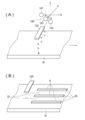
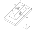
- FIG. 10A is a diagram illustrating a state in which a coating material is applied to an object to be coated by the inkjet unit of the coating apparatus according to Embodiment A, and FIG. 10B is a state of the object to be coated after coating.
- FIG. 10A is a diagram illustrating a state in which a coating material is applied to an object to be coated by the inkjet unit of the coating apparatus according to Embodiment A, and FIG. 10B is a state of the object to be coated after coating.
- FIG. 15A is an initial state
- FIG. 15B is a drawing of an object to be coated after the discharge process is completed
- FIG. 15C is a plating solution immersion
- FIG. . It is a figure when two or more inkjet parts are provided.
- a surface treatment substrate comprising: a surface treatment of a substrate having the mask pattern; and a step of removing a masking agent constituting the mask pattern with a refrigerant having a temperature lower than the melting point of the paraffin to obtain a surface treatment substrate.
- surface treatment means modifying the surface of a substrate by a physical or chemical method.
- the surface treatment method is not particularly limited, and examples thereof include chemical modification methods such as plating, etching, plating electroforming, and surface roughening; and physical modification methods such as polishing and sputtering.
- any of the above surface treatments can be applied.
- plating and etching are performed as a representative embodiment will be described in detail.
- the surface treatment is a plating treatment. That is, according to one embodiment of the present invention, a masking agent containing paraffin is heated to a temperature equal to or higher than the melting point of the paraffin to prepare a masking solution (masking solution preparation step), and the masking solution is patterned on the substrate. Forming a mask pattern (masking liquid patterning step), plating the substrate having the mask pattern to form a metal layer on the non-mask pattern portion (plating step), And a step of removing the masking agent constituting the mask pattern with a refrigerant having a temperature lower than the melting point of the paraffin (masking agent removing step).
- This embodiment is characterized in that a masking agent containing paraffin is used as a masking agent. That is, according to one form of this invention, the masking agent containing a paraffin is provided.
- a masking agent containing paraffin is used as a masking agent.
- the masking agent containing paraffin used in this embodiment is excellent in chemical resistance against the plating solution, etc., and when the masking agent is applied, the coating part and the substrate are in close contact with each other. For this reason, the plating solution does not enter between the mask pattern and the substrate at the time of plating, and the accuracy of the plating finish can be improved. Moreover, the masking agent of this form can be easily removed using a refrigerant after plating. Furthermore, the masking agent after the plating treatment can be collected and reused. Therefore, it is possible to perform a plating process with a small environmental load without adversely affecting the formation pattern.
- the masking agent according to the present invention comprises paraffin and, if necessary, a colorant and other additives.
- paraffin refers to an alkane having 20 or more carbon atoms (chain saturated hydrocarbon having a general formula of C n H 2n + 2 ). Paraffin has high chemical stability and excellent chemical resistance (alkali resistance and acid resistance) to surface treatment agents such as highly corrosive etching solutions and plating solutions. For this reason, the composition containing paraffin can be used as a masking agent in the surface treatment such as etching or plating treatment. As described later, the surface treatment using a masking agent containing paraffin is applied with a masking agent in a molten state to form a mask pattern, and then subjected to a surface treatment such as etching or plating, and then cooled to below the melting point. As a result, the masking agent is removed. Paraffin also has the advantage of high safety to the human body, and the handling of the masking agent is improved by producing the masking agent using paraffin.
- the paraffin that can be used in the present invention is not particularly limited, and is preferably a chain saturated hydrocarbon having 20 to 80 carbon atoms, and more preferably a chain saturated hydrocarbon having 20 to 40 carbon atoms.
- the paraffin may be linear or branched. Paraffin may be composed of a uniform material, but is usually a mixture of two or more types of chain saturated hydrocarbons (paraffins) having different carbon chains.
- the number average molecular weight Mn of the paraffin is preferably 220 to 480, more preferably 220 to 300, and further preferably 220 to 260. Thereby, melting
- the average carbon number of paraffin is preferably 20-40.
- the higher the carbon number the higher the melting point of paraffin. Therefore, by changing the number of carbons contained, the melting point of the paraffin can be set in a desired range, and the adhesion to the substrate and the peelability during cooling can be improved.
- the melting point of paraffin varies depending on the use of the masking agent, paraffin that is solid at normal temperature (25 ° C.) is preferable. More preferably, the melting point of paraffin is 40 ° C or higher, and further 50 ° C or higher. More preferably, it is 60 degreeC or more, More preferably, it is 65 degreeC or more. Removal of the masking agent and surface treatment (plating treatment, etching treatment) described later must be performed at a temperature below the melting point of paraffin. Therefore, in such a case, removal of the masking agent including paraffin and surface treatment can be easily performed, and the selection range of these treatment temperatures is wide, which is preferable.
- the melting point is particularly preferably 75 ° C. or higher.
- the upper limit of the melting point is not particularly limited, but if the melting point is 200 ° C. or lower, the masking agent comprising paraffin can be applied under mild conditions, and various coating apparatuses and coating methods can be used. It is preferable because it can be adopted.
- the melting point is more preferably 150 ° C. or lower. More preferably, the melting point is 100 ° C. or less, and particularly preferably 85 ° C. or less, from the viewpoint that the peelability of the masking agent after the surface treatment is good.
- paraffin wax produced by separating and refining from a petroleum vacuum distilled oil specified in JIS K 2235: 2009, or synthetic paraffin derived from petroleum mineral, synthetic wax, and the like.
- synthetic paraffin derived from petroleum mineral, synthetic wax, and the like As a commercial product, Nippon Seiwa Co., Ltd. "PARAFFINWAX" series can be mentioned as a suitable example.
- the masking agent may be composed only of the above paraffin. However, the masking agent may be a masking composition containing paraffin and, if necessary, a colorant and other additives.
- the masking agent preferably contains a colorant. Since paraffin is translucent to white at normal temperature, the visibility of the masking pattern formed by the masking agent is improved by adding a colorant.
- the colorant is not particularly limited, and conventionally known pigments and / or dyes can be used.
- pigments examples include Pigment Red 3, 5, 19, 22, 31, 38, 43, 48: 1, 48: 2, 48: 3, 48: 4, 48: 5, 49: 1, 53: 1, 57. : 1, 57: 2, 58: 4, 63: 1, 81, 81: 1, 81: 2, 81: 3, 81: 4, 88, 104, 108, 112, 122, 123, 144, 146, 149 166, 168, 169, 170, 177, 178, 179, 184, 185, 208, 216, 226, 257, Pigment Violet 3, 19, 23, 29, 30, 37, 50, 88, Pigment Orange 13, 16 , 20, 36, etc .; Pigment Blue 1, 15, 15: 1, 15: 2, 15: 3, 15: 4, 15: 6, 16, 17-1, 2 27, 28, 29, 36, 60, etc.
- Black pigments such as Pigment Black 7, 28, and 26; white pigments such as Pigment White 6, 18, and 21 can be used according to the purpose.
- the dye is preferably an oil-soluble dye that is substantially insoluble in water.
- the oil-soluble dye means one having a solubility in water at 25 ° C. (mass of dye that can be dissolved in 100 g of water) of 1 g or less, preferably 0.5 g or less, more preferably What is 0.1 g or less is preferable.
- pigments and / or dyes may be used alone or in combination of two or more.
- the average particle diameter of the colorant particles is preferably 1 to 20 ⁇ m, more preferably 1 to 10 ⁇ m, more preferably 1 to 5 ⁇ m, More preferably, it is 1 to 2 ⁇ m.
- the masking agent is applied by an ink jet method, clogging of the head nozzle can be suppressed and the storage stability of the ink can be maintained, which is preferable.
- the masking agent is a dispersant for improving the dispersibility of the colorant, a surfactant for adjusting the surface tension of the masking agent, a viscosity adjusting agent, an adhesiveness-imparting material for improving the adhesiveness, An additive such as a plasticizer for imparting flexibility or an antioxidant for imparting thermal stability may be included.
- the content of paraffin in the masking composition as a masking agent is 85% by weight or more and less than 100% by weight with respect to the total weight of the masking agent (masking composition) from the viewpoint of sufficiently exerting chemical resistance. It is preferably 90% by weight or more and 99.99% by weight or less from the viewpoint of preventing chemical reaction with the plating solution, and 95% by weight or more and 99.99% from the point of further preventing chemical reaction with the plating solution. More preferably, it is 99 weight% or less.
- the content of the colorant in the masking composition is appropriately selected depending on the purpose of use, but is 0.01 to 10% by mass with respect to the total weight of the masking composition in consideration of the coating property and colorability of the masking agent.
- the content is preferably 0.01 to 5% by mass, more preferably 0.01 to 1% by mass.
- the content of other additives in the masking composition is not particularly limited as long as it does not impair the effects of the present invention, but is usually 0.1 weight relative to the total weight (100 parts by weight) of paraffin and colorant. Part to 10 parts by weight is preferable.
- a masking agent containing a colorant and / or an additive
- a paraffin in a molten state and a colorant and / or an additive such as a ball mill, a sand mill, an attritor, a roll mill, an agitator, and a Henschel.
- the mixing can be performed by using a dispersion device such as a mixer, a colloid mill, an ultrasonic homogenizer, a pearl mill, a wet jet mill, or a paint shaker.
- the masking agent preferably has a viscosity at 80 ° C. of 5 to 30 mPa ⁇ s.
- various coating apparatuses and coating methods including an inkjet method can be employed.
- the viscosity of the masking agent after ejection / landing varies depending on the object (material such as lead frame and surface finish).
- the viscosity is preferably high from the viewpoint of preventing ink sag after ejection, but if the viscosity is too high, the elongation of the ink is poor, and even if the resolution is increased, it may be difficult to form a uniform coated surface.
- the viscosity is preferably 5 to 20 mPa ⁇ s, and more preferably 8 to 20 mPa ⁇ s.
- the viscosity of the masking agent can be adjusted to a desired range by adjusting the composition of paraffin (the type and content ratio of the chain saturated hydrocarbon) constituting the masking agent or by adding a viscosity modifier. .
- the viscosity of the masking agent is the average of the values obtained by measuring the viscosity 5 times every 100 seconds after the temperature is changed to a predetermined temperature with a temperature-variable rotary viscometer (eg, TVB-35 manufactured by Toki Sangyo Co., Ltd.). Say.
- the measurement conditions are a shear rate of 10 (1 / s) and an elevated temperature of 5 ° C./5 seconds.
- a mask pattern is formed by the masking liquid preparation process and the masking liquid patterning process. Therefore, according to another embodiment of the present invention, a step of preparing a masking liquid by heating a masking agent containing paraffin to a temperature equal to or higher than the melting point of the paraffin (masking liquid preparation step), and the masking liquid on the substrate And a step of patterning to form a mask pattern (masking liquid patterning step).
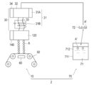
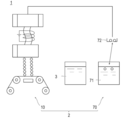
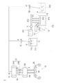
- Masking solution production process (101 in FIG. 1)
- a masking agent containing paraffin is heated to a temperature equal to or higher than the melting point of the paraffin to prepare a masking solution.
- a masking liquid is obtained by heating the masking agent which consists of the said paraffin only, or the masking agent as a masking composition containing paraffin to the temperature more than melting
- the masking composition the paraffin is heated to a molten state, and then the above colorant and / or other additives are added to the mixture and mixed with a mixing and dispersing device, and used as a masking solution. Also good.
- the heating means for the masking agent is not particularly limited, and a conventionally known heating device can be used.
- the masking agent can be heated and melted using an ink supply device having a heating and melting function attached to the hot melt ink printing apparatus. When heating and melting, stirring may be performed as necessary.
- the heating temperature is not particularly limited as long as it is higher than the melting point of paraffin.
- the “melting point of paraffin” refers to the melting point of the paraffin having the lowest melting point among the paraffins contained in the masking agent.
- the upper limit of the heating temperature is not particularly limited as long as it is less than the boiling point of paraffin, but is preferably 180 ° C. or less from the viewpoint of heat resistance of the coating apparatus (for example, an inkjet head).
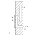
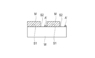
- Masking solution patterning step (102 in FIG. 1) Subsequently, as shown in FIG. 2B, the masking liquid is patterned on the substrate 21 to form a mask pattern 22. Specifically, the mask pattern 22 is formed by selectively applying the molten masking liquid obtained in the previous step onto the substrate 21 and drying it.
- the means for applying the masking liquid is not particularly limited, and commonly used printing techniques such as inkjet method, gravure printing, gravure offset printing, flexographic printing, and screen printing can be used. Examples thereof include a method capable of printing by direct output from an electronic device such as a non-contact ink jet method (more specifically, a piezo ink jet method).
- the temperature of the masking liquid at the time of application is preferably a temperature of melting point + 20 ° C. or higher, more preferably a temperature of melting point + 30 ° C. or higher, from the viewpoint of improving coating properties.
- the upper limit is not particularly limited as long as it is less than the boiling point of paraffin, but is preferably 180 ° C. or less from the viewpoint of heat resistance of the coating apparatus (for example, an inkjet head), and more preferably 140 ° C. from the viewpoint of the coating apparatus. preferable.
- the temperature is (melting point + 50 ° C.) or less of the masking agent.
- the drying temperature of the mask pattern is not particularly limited, but is preferably 24 ° C. to 60 ° C. from the viewpoint of suppressing peeling of the masking pattern due to rapid shrinkage, and 50 ° C. to 60 ° C. from the viewpoint of improving ink elongation after coating. It is.
- the upper limit is not particularly limited as long as it is lower than the melting point of the paraffin constituting the masking agent. However, it is preferably 24 ° C. to 50 ° C. in terms of elongation of paraffin, and more preferably 24 ° C. to 30 ° in terms of edge formation. ° C.
- the substrate coated with the masking liquid is heated after the masking liquid is applied on the substrate and dried.
- the step of forming the mask pattern includes a step of applying the masking liquid on the substrate and a step of heating the substrate on which the masking liquid is applied.
- a sharp edge can be formed in the mask pattern formed on the pin connector, and it is possible to prevent the loss of the terminal shape, improve the linearity, and form a smooth curve.
- the adhesion between the masking solution (masking agent) and the substrate can be improved.
- the ink when applying hot melt ink such as paraffin wax, the ink is divided into several times in order to reduce, reduce or eliminate the gap (gap) between the landed inks (to improve the application density). A method of landing (coating) thickly is preferable.
- the gap (gap) between the inks can be reduced without performing multi-layer coating by a very simple method of heating the substrate coated with the masking agent (masking solution) as described above. Or, since it can be prevented, the amount of the masking solution used can be significantly reduced, and the time for the coating process can be drastically shortened.
- the heating temperature (substrate surface temperature) of the substrate coated with the masking liquid is preferably 70 to 110 ° C. If it is 110 degrees C or less, it can prevent that the fluidity
- the heating temperature (substrate surface temperature) of the substrate coated with the masking liquid is more preferably 75 to 105 ° C., and further preferably 78 to 103 ° C.
- the substrate is heated to a temperature not lower than the melting point of paraffin constituting the masking agent and not higher than the melting point of paraffin + 5 ° C. or lower.
- the heating time of the substrate depends on the heating temperature, it is preferably 10 seconds or longer in order to sufficiently obtain the effect of improving the coating density.
- the upper limit of the heating time is not particularly limited, but is preferably 15 seconds or less from the viewpoint of controlling the target design shape and value.
- the means for heating the substrate coated with the masking liquid is not particularly limited, and examples thereof include a method of locally heating or keeping the substrate using a heat source such as an infrared heater or a halogen heater.
- the thickness of the mask pattern is not particularly limited, but is preferably 0.1 ⁇ m to 100 ⁇ m, more preferably 1 ⁇ m to 50 ⁇ m. If the thickness of the mask pattern is equal to or more than the lower limit value, occurrence of pinholes can be suppressed. For this reason, the function as a mask can be fully fulfill
- the ink is thickened several times (multilayer) in order to reduce or prevent a gap (gap) between the landed inks (to improve the application density).
- the thickness of the mask pattern is preferably 10 ⁇ m to 100 ⁇ m, and more preferably 10 ⁇ m to 50 ⁇ m.
- the masking solution is applied on the substrate and dried, and then the substrate on which the masking solution is applied is heated, or the masking solution is applied on a heated or heat-retained substrate as described later.
- the gap (gap) between the landed inks can be significantly reduced or prevented (the coating density is improved). Therefore, in such a case, even if the mask pattern has a thinner thickness, it is possible to prevent a problem that the plating process is applied to the gap between the landed masking agents, and a thickness of 0.1 ⁇ m or more is sufficient. More preferably, the thickness is 1 ⁇ m to 20 ⁇ m from the viewpoint of reducing the amount of ink and reducing the coating time.
- the width of the mask pattern is not particularly limited and is set according to the pattern to be formed.
- the pattern formation width can be formed to an arbitrary width by connecting a plurality of inkjet heads.
- the substrate is not particularly limited, but a resin film such as a glass epoxy material, a polyimide film, a polyamide film, a polyester film, a polytetrafluoroethylene film, a polyphenylene sulfide film, a polyethylene naphthalate film, or a liquid crystal polymer film.
- a resin film such as a glass epoxy material, a polyimide film, a polyamide film, a polyester film, a polytetrafluoroethylene film, a polyphenylene sulfide film, a polyethylene naphthalate film, or a liquid crystal polymer film.
- BT resin silicon wafer, glass, liquid crystal film, aramid, ceramic, copper, silver, tin, nickel, gold and the like.
- a substrate in which a conductive layer such as copper, silver, tin, nickel, or gold is formed on these substrates for example, a resin film with a metal thin film in which a metal thin film is formed on the surface of a resin film such as a polyimide film is used.
- the conductive layer can function as a metal wiring and may be provided on the entire surface of the substrate or may be formed in a pattern.
- the thickness of the conductive layer is not particularly limited. That is, in this embodiment, a wiring board or an electronic component can be used as a substrate, and a metal pattern (metal layer) by plating can be formed on the wiring board or the electronic component.
- wiring board refers to a printed wiring board represented by a mother board, a central processing circuit (CPU), a chip set, a ceramic board, a package board represented by a touch panel board, and the like.
- Electrical components refers to semiconductor chips, connectors, sockets, and the like. Further, the wiring board or the electronic component includes the wiring board provided with the electronic component.
- the shape of the substrate is not particularly limited, and may be a sheet shape, a plate shape, a roll shape, or a hoop shape.
- a roll a sheet or plate attached to a rotating body (roll) may be used.
- a hoop shape a configuration in which rolls are installed at two to several locations inside the hoop and a hoop-shaped conductive base material is passed through the roll can be considered. Since it is possible to continuously produce a surface-treated substrate in both a roll shape and a hoop shape, the production efficiency is higher than that of a sheet shape or a plate shape, which is preferable.
- the thickness of the substrate is not particularly limited, but is preferably in the range of 5 ⁇ m to 3 mm.
- the thickness is preferably in the range of usually 5 ⁇ m to 20 ⁇ m.
- the temperature of the substrate at the time of masking application is not particularly limited and may be any ambient temperature, but is preferably in the range of 18 to 60 ° C.
- the temperature of the substrate at the time of masking application refers to the temperature of the surface (application surface) of the substrate to which the masking liquid is applied.
- the accuracy of the mask pattern can be improved by managing the substrate within the above range at the time of masking application.
- the temperature is preferably 24 ° C. to 60 ° C. from the viewpoint of suppressing peeling of the masking liquid (masking agent) due to rapid shrinkage.
- the substrate during masking application is heated or kept warm.
- the step of forming the mask pattern includes a step of applying the masking liquid onto a substrate that is heated or kept warm.
- the ink elongation of the applied masking liquid (masking agent) is improved, and the gap (gap) between the landed inks can be reduced, reduced, and prevented, and the resolution of the mask pattern is improved.
- the mask pattern at the edge portion can be made smooth, a smooth edge can be formed.
- the adhesion between the masking solution (masking agent) and the substrate can be improved.
- the ink when applying hot melt ink, in order to reduce or prevent voids (gap) between the landed inks (increase the coating density), the ink is made thick (multi-layered) in several steps.
- the method of applying) is preferable.
- the gap (gap) between the inks can be reduced or prevented without performing multi-layer coating by a very simple method of heating or keeping the substrate on which the masking agent is landed as described above. Therefore, the amount of masking solution used can be significantly reduced, and the coating process time can be dramatically shortened.
- the temperature of the substrate that is heated or kept warm is preferably 40 to 50 ° C. If it is 50 degrees C or less, it can prevent that the fluidity
- heating refers to positively applying heat. Therefore, the heated state includes the case where heat is applied to the substrate in the initial state to raise the temperature to a certain temperature and then heat is not applied, or the case where heat is constantly applied to the substrate as well as the initial state. It is.
- heat retention refers to making it difficult to release heat without giving heat, that is, making it difficult to lower the temperature.
- the means for heating or keeping the substrate at the time of masking application is not particularly limited.
- a method of locally heating or keeping the substrate using a heat source such as an infrared heater or a halogen heater, or a constant temperature bath kept at a constant temperature.
- a substrate is placed inside and a substrate that has reached thermal equilibrium (that is, a substrate that has been heated or kept warm) is used.
- the substrate may be pretreated prior to the immersion treatment in the plating solution.
- the pretreatment include blast treatment, alkali washing, acid washing, water washing, organic solvent washing, cleaning treatment such as bombardment treatment, etching treatment, and formation of a base layer.
- Examples of the constituent material of the metal layer include Ni, Cu, Ag, Au, Cr, Zn, Sn, Sn—Pb alloy, and the like.
- the thickness of the metal layer formed by the plating treatment is not particularly limited, but is preferably 0.5 ⁇ m or more in order to exhibit sufficient conductivity. On the other hand, the upper limit is not particularly limited.
- the method of plating treatment is not particularly limited, and for example, treatment such as electrolytic plating and electroless plating can be performed.
- the electroless plating method includes three steps: (1) a hydrophilization step, (2) a catalyst step, and (3) an electroless plating step.
- the hydrophilization step can be omitted depending on the type of substrate.
- the substrate is oxidized with chromic acid, chromic anhydride-sulfuric acid mixture, permanganic acid, etc .; strong acid such as hydrochloric acid, sulfuric acid, hydrofluoric acid, nitric acid, sodium hydroxide, potassium hydroxide, etc.
- strong acid such as hydrochloric acid, sulfuric acid, hydrofluoric acid, nitric acid, sodium hydroxide, potassium hydroxide, etc.
- a catalyst layer serving as a base point of electroless plating performed in the next step is formed on the surface of the substrate.
- the method for forming the catalyst layer is not particularly limited, and may be performed using a commercially available catalyzing reagent for electroless plating.
- a solution containing palladium chloride and stannous chloride is used as a catalyzing reagent, and the substrate is immersed in this solution to adsorb the catalytic metal to the surface of the substrate, and then an acid such as sulfuric acid or hydrochloric acid, sodium hydroxide, etc.
- palladium is deposited on the substrate surface (catalyst-acceleration method), or by contacting the substrate with stannous chloride, the tin ions are adsorbed on the substrate surface. Thereafter, a method of depositing palladium on the substrate surface by dipping in a palladium chloride solution (sensitizing-activation method) and the like can be mentioned.
- the substrate is immersed in an electroless plating bath containing a metal salt, a reducing agent, a complexing agent, etc., and electroless plating is performed.
- the metal salt examples include the metal salts described above as the metal constituting the metal layer.
- nickel salt when nickel salt is used, nickel chloride, nickel sulfate, nickel acetate and the like can be mentioned. What is necessary is just to set suitably the density
- Examples of the reducing agent include sodium hypophosphite, dimethylamine borane, sodium borohydride, potassium borohydride, hydrazine and the like.
- the complexing agent examples include citric acid, hydroxyacetic acid, tartaric acid, malic acid, lactic acid, gluconic acid, carboxylates such as alkali metal salts and ammonium salts thereof, amino acids such as glycine, ethylenediamine, and alkylamines. Aminic acid, an ammonium compound, EDTA, pyrophosphoric acid (salt), etc. are mentioned. Only 1 type may be used for the said complexing agent and it may use 2 or more types together.
- the pH of the electroless plating bath in the electroless plating method is preferably 4 to 14.
- the reaction when a substrate is added, the reaction starts quickly and is accompanied by generation of hydrogen gas.
- the end of the electroless plating process in the electroless plating method can be determined when the generation of the hydrogen gas is not completely recognized.
- the plated product is taken out from the reaction system, and washed and dried as necessary.
- the electroless plating process may be repeated a plurality of times. By doing in this way, a multilayer metal layer can be coat
- the electrolytic plating method involves immersing an object to be plated as a part of a cathode in an aqueous solution or a non-aqueous solution in which a metal salt as a plating solution and, if necessary, a brightening agent and a surfactant are dissolved.
- a current is applied, and a metal, for example, nickel, chromium, copper, or the like is deposited on the cathode plating object by electrolysis from the plating solution.
- the object to be plated needs to have conductivity.
- a member in which a conductive layer is formed on the substrate as described above can be used as a member to be plated.
- the metal salt is not particularly limited as long as it is a metal salt constituting the metal layer, and the concentration of the metal salt in the plating solution is the size of the substrate (surface area so that a metal layer having a desired thickness is formed. ) May be set as appropriate.
- ⁇ Plating temperature varies depending on the type of plating solution and plating method (electrolytic plating, electroless plating). Usually, the temperature of the plating solution is 40 to 80 ° C. in the case of electroless plating, 20 to 70 ° C. in the case of electrolytic plating, and preferably 50 to 65 ° C. However, in general, when an alkaline solution or a cyan solution is used, the electrolytic plating temperature is 50 ° C. or higher. Further, the electroless plating treatment is often performed at 50 ° C. or higher.
- the temperature is not particularly limited as long as it is a temperature at which melting of the masking agent can be prevented during the plating treatment, and may be lower than the melting point of the paraffin constituting the masking agent. It is preferable to perform the plating process at a melting point of paraffin of ⁇ 10 ° C. or lower.
- the masking agent is constituted by using a paraffin having a melting point of the plating treatment temperature (plating solution temperature) +10 to + 50 ° C., more preferably the plating treatment temperature (plating solution temperature) +10 to + 30 ° C. .
- the plating treatment at a temperature of the melting point of the paraffin constituting the masking agent from ⁇ 10 to ⁇ 50 ° C., more preferably at a temperature of the melting point of the paraffin from ⁇ 10 to ⁇ 30 ° C.
- the time for the plating process is appropriately adjusted depending on the temperature of the plating process, the type of plating solution, and the like.
- the plating solution temperature is 65 ° C. and it is 60 minutes.
- plating solutions include copper cyanide plating solution, copper pyrophosphate plating solution, copper sulfate plating solution, nickel plating solution, nickel sulfamate plating solution, chromium plating solution, zinc cyanide plating solution, nocyanine zinc plating solution, alkaline
- Conventionally known plating solutions such as tin plating solution, acidic tin plating solution, silver plating solution, gold cyanide plating solution, and acidic gold plating solution can be used.
- the masking agent (masking pattern) of this embodiment can achieve excellent adhesion and peelability of the mask pattern by controlling the coating temperature of the masking agent, the plating treatment temperature, and the removal temperature of the masking agent. Therefore, compared with the masking tape used in the conventional plating process, it is excellent in adhesiveness and peelability, and the accuracy of plating finish can be improved.
- the refrigerant may be a liquid or gaseous medium having a melting point lower than that of paraffin.
- the liquid may be acidic, alkaline, or neutral, but if it is acidic or alkaline, the metal layer (metal pattern) formed by surface treatment such as plating may be adversely affected, such as discoloration. There is. Therefore, when using a liquid, it is preferable that it is neutral. That is, the refrigerant is preferably cold air and / or neutral liquid. More preferably, it is a neutral liquid.
- the plating apparatus is attached with a cleaning apparatus for cleaning the substrate after plating, and when a neutral liquid is used, an existing cleaning apparatus can be used for removing the masking. Therefore, it is not necessary to provide a new device / equipment for removing the masking agent. Furthermore, the masking agent can be removed simultaneously with the conventional substrate cleaning, which is advantageous in terms of the manufacturing process.
- Cooling air includes cooling gas such as air, nitrogen and carbon dioxide.
- the neutral liquid is not particularly limited as long as it is a neutral liquid that does not dissolve paraffin, and a known liquid can be appropriately selected according to the paraffin used.
- a known liquid can be appropriately selected according to the paraffin used.
- ketone solvents such as methyl ethyl ketone, acetone, diethyl ketone, methyl isobutyl ketone, methyl isopropyl ketone, cyclohexanone, 3-heptanone and 4-heptanone
- water is preferred.
- the water can be appropriately selected from pure water, tap water, ground water, distilled water, ion-exchanged water, etc. Among these, contamination of impurities is prevented, and it is recovered in a masking agent recovery step described later. From the viewpoint of preventing a decrease in the purity of the masking agent, pure water is preferably used. In addition, these can be used individually or in mixture of 2 or more types.
- neutral means a pH range of 5 to 9, preferably a pH range of 6 to 8, and more preferably a pH range of 6 to 7.
- the temperature of the refrigerant is not particularly limited as long as it is lower than the melting point of paraffin and can be peeled off by contraction of paraffin. Since the shrinkage rate of paraffin depends on the melting point of paraffin, it can be appropriately set according to the melting point of paraffin used for the masking agent. Specifically, in order to improve the peelability, it is preferably (melting point of paraffin ⁇ 60) ° C. or less, more preferably (melting point of paraffin ⁇ 70) ° C. or less, and (melting point of paraffin). More preferably, it is ⁇ 80) ° C. or lower. For example, the temperature of the refrigerant is preferably 25 ° C. or less from the viewpoint of simplicity, more preferably 10 ° C.
- the lower limit of the refrigerant temperature is not particularly limited.
- the temperature can be -196 ° C.
- the removal by the refrigerant can be performed under normal pressure, under pressure, or under reduced pressure, and is not particularly limited.
- the method for removing the masking agent constituting the mask pattern using a refrigerant is not particularly limited.
- a method of blowing cold air onto the surface of the mask pattern can be mentioned.
- coolant to a mask pattern the method of immersing the board
- it is a method of immersing a substrate having a mask pattern in a neutral liquid.
- cold air and neutral liquid are used in combination, a method of spraying cold air and then immersing the neutral liquid in a jet / shower or neutral liquid is preferable.
- the blowing speed is preferably in the range of 200 to 800 m / s, and the blowing time is preferably 5 seconds to 1 minute, although it depends on the temperature of the cold air and the blowing speed.
- the immersion time varies depending on the temperature of the liquid, but is usually preferably 30 seconds to 50 minutes, and more preferably 5 minutes to 30 minutes. Moreover, you may add an ultrasonic vibration etc. as needed during immersion. It is pure water / distilled water that can be more accurately peeled off.
- the jetting / shower time is appropriately set according to the temperature of the liquid.
- the method of the present embodiment is the step of removing the masking agent with a refrigerant, and after cooling the mask pattern, the masking agent is cooled by a refrigerant having a temperature lower than the melting point of the paraffin. May be removed.
- the method for cooling the mask pattern is not particularly limited, and air cooling, water cooling, or the like may be performed.
- Masking agent recovery process (105 in FIG. 1) Next, the masking agent removed by the refrigerant is collected as necessary. Although the masking agent removed after the plating treatment may be discarded as it is, the removed masking agent is recovered from the viewpoint of reducing the environmental load, and preferably, the recovered masking agent is reused.
- the recovery method of the masking agent is not particularly limited, and examples thereof include a method of precipitating or floating the removed masking agent in a liquid (recovery liquid) and recovering it.
- the masking agent cooled and removed by the refrigerant is in a solid lump state. Therefore, it can be easily recovered by precipitating or floating these solid masses of the masking agent.
- the usable liquid (recovered liquid) is not particularly limited as long as it does not dissolve the masking agent.
- the collecting step includes collecting the removed masking agent by suspending it in a neutral liquid having a specific gravity greater than that of the masking agent.
- a neutral liquid having a specific gravity greater than that of the masking agent.
- water particularly preferably pure water
- the density of paraffin is usually about 0.85 to 0.89 g / cm 3 at 20 ° C., and its specific gravity is smaller than that of water. Therefore, the masking agent can be recovered easily and inexpensively by using water as the recovery liquid. In addition, it is easy to dispose of water after use, which is preferable for environmental conservation.
- the neutral liquid for removing the masking agent (removal liquid) and the recovery liquid for recovering the masking agent may be the same or different. It may be.
- the removal liquid and the recovery liquid are preferably the same from the viewpoints of cost and simplification of the manufacturing process. More preferably, the removal of the masking agent in the previous step is performed by immersing the substrate having the mask pattern in a neutral liquid, and the mask pattern is precipitated or floated in the neutral liquid after the step. The masking agent that constituted was recovered. In such a case, the mask pattern can be removed and the masking agent can be recovered with the same neutral liquid.
- a neutral liquid having a specific gravity greater than that of the masking agent is used as the removal liquid and the recovery liquid.
- the neutral liquid is water, and particularly preferably pure water.
- the temperature of the recovered liquid is not particularly limited as long as it is lower than the melting point of paraffin.
- the temperature is preferably 25 ° C. or less from the viewpoint of simplicity, more preferably 10 ° C. or less, further preferably 5 ° C. or less, and particularly preferably 0 ° C. or less from the viewpoint of shortening the peeling time.
- the lower limit of the recovered liquid is not particularly limited.
- the masking agent collected above can be reused as it is for preparing the masking solution. That is, the masking liquid can be produced by heating the recovered masking agent as it is above the melting point. Alternatively, as necessary, impurities in the recovered masking agent, for example, metal pieces, metal particles, dust, dust, and the like generated by plating or the like may be removed and reused. Therefore, the manufacturing method of the surface treatment substrate using the masking agent of the present embodiment is a simple and low-cost method, and the masking agent can be reused substantially completely. It is an epoch-making method that can significantly reduce or eliminate the problem. However, if necessary, the recovered masking agent may be purified and reused.
- the surface treatment is an etching treatment. That is, according to one embodiment of the present invention, a step of preparing a substrate on which a metal layer is formed (substrate preparation step), and a masking agent containing paraffin is heated to a temperature equal to or higher than the melting point of the paraffin for masking. A step of preparing a liquid (masking solution preparation step), a step of patterning the masking solution on the metal layer to form a mask pattern (masking solution patterning step), and etching the substrate having the mask pattern.
- a method for producing a surface-treated substrate comprising: a step (etching step); and a step of removing the masking agent constituting the mask pattern with a refrigerant having a temperature lower than the melting point of the paraffin (masking agent removing step). Is done.
- the masking agent described above may be used to form a mask pattern for etching.
- a conventional etching process using a dry film resist it is difficult to reuse used dry film waste material after the etching process, and there is a problem that the burden on the environment is large.
- the etching process has a problem that the alkaline aqueous solution used for removing the cured resist film after etching has an adverse effect such as discoloration of the metal pattern.
- the masking agent can be easily removed using a non-alkaline refrigerant, and further recovered and reused. Therefore, an etching process with a small environmental load is possible without adversely affecting the formation pattern.
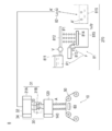
- Substrate preparation process (201 in FIG. 3) First, as shown in FIG. 4A, a substrate 41 having a metal layer 43 formed on the surface is prepared.
- the substrate 41 is not particularly limited, and those exemplified as the substrate 21 in the embodiment according to the method for producing a surface treatment base material by the plating treatment are preferably exemplified.
- the thickness of the substrate is not particularly limited, but is preferably in the range of 5 ⁇ m to 10 mm.
- the constituent material of the metal layer 43 is not particularly limited, and examples thereof include Ni, Cu, Ag, Au, Cr, Zn, Sn, Sn—Pb alloy and the like.
- the thickness of the metal layer is not particularly limited, but is preferably 0.5 ⁇ m or more in order to exhibit sufficient conductivity.
- the upper limit is not particularly limited.
- the metal layer may be formed by (vacuum) vapor deposition, sputtering, CVD, magnetron sputtering, plating, cluster ion beam, ion plating, or the like. Any method may be used, but since the production efficiency is high, the magnetron sputtering method is generally used industrially. Or you may use wiring boards and electronic components, such as a board
- the metal plate itself may be etched using a substrate made of a metal plate instead of the substrate 41 having the metal layer 43 formed on the surface.
- the metal plate those exemplified as the metal plate of the substrate 21 can be used.
- Masking solution preparation process (202 in FIG. 3) Subsequently, a masking solution is prepared.
- the method for producing the masking liquid is the same as the method according to the embodiment relating to the method for producing the surface-treated substrate by the plating treatment, and a detailed description thereof will be omitted.
- Patterning process of masking solution (203 in FIG. 3)
- the masking liquid is patterned on the metal layer 43 to form a mask pattern 42.
- a specific patterning method of the masking liquid is the same as the method according to the embodiment related to the method of manufacturing the surface treatment base material by the plating process except that the masking liquid is patterned on the metal layer 43 instead of the substrate 21. Specific description will be omitted.
- the coating surface on which the masking liquid is applied that is, the surface of the metal layer 43 is heated or kept at the above-described temperature.
- the coated surface coated with the masking agent that is, the surface of the metal layer 43 is brought to the above-described temperature. It is preferable to heat.
- the etching method is not particularly limited, and examples thereof include a method of immersing a substrate having a mask pattern in an etching solution or a method of spraying with an etching solution.
- the etching solution may be determined according to the type of the metal layer to be etched, and examples thereof include acid etching solutions having various compositions, alkali etching solutions, copper ammonium solutions, ferric chloride solutions, and cupric chloride solutions. .
- the acid etching solution for example, a general acid aqueous solution containing at least one kind of sulfuric acid, hydrochloric acid, hydrofluoric acid, phosphoric acid, nitric acid, organic acid and the like can be used.
- an acid aqueous solution containing sulfuric acid or hydrochloric acid is preferable, and sulfuric acid and hydrochloric acid are particularly preferably used in combination.
- the ratio of sulfuric acid to the whole etching solution is preferably in the range of 1 to 50% by mass, more preferably in the range of 3 to 30% by mass, particularly preferably 12 in terms of the etching rate.
- the ratio of hydrochloric acid to the entire etching solution is preferably in the range of 0.1 to 20% by mass, more preferably in the range of 0.5 to 15% by mass. It is particularly preferably in the range of 7 to 10% by mass.
- alkaline etchant there are no particular restrictions on the alkaline etchant.
- a common alkaline aqueous solution such as lithium hydroxide, potassium hydroxide, sodium hydroxide, ammonia, tetramethylammonium hydroxide, choline, or a mixed solution thereof with hydrogen peroxide can be used.
- a sodium hydroxide aqueous solution or an ammonium aqueous solution having a concentration of 40% by mass or more, more preferably 45% by mass or more is preferable.
- water should be evaporated from these alkaline aqueous solutions.
- the etching solution can be easily prepared by dissolving the above components in water.
- the water is preferably water from which ionic substances and impurities such as ion-exchanged water and pure water have been removed.
- the temperature of the etching solution is not particularly limited, but is not particularly limited as long as the masking agent can be prevented from melting during the etching process, and may be lower than the melting point of the paraffin constituting the masking agent.
- the etching process is performed at a melting point of paraffin of ⁇ 10 ° C. or lower.
- the lower limit is not particularly limited, but is preferably 25 ° C. or higher.
- the etching treatment is performed at a temperature of the melting point of the paraffin constituting the masking agent from ⁇ 10 to ⁇ 50 ° C., more preferably at a temperature of the melting point of the paraffin from ⁇ 10 to ⁇ 30 ° C.
- the etching solution may further contain other components as appropriate.
- other components include a surfactant that improves wettability to the metal layer, an antifoaming agent that suppresses foaming during etching by a spray method, and a rust preventive agent that prevents discoloration of copper.
- Etching treatment time is appropriately adjusted depending on the type of etching solution, the temperature of the etching solution, the spray pressure, and the like.
- the temperature of the etching solution is usually 50 ° C. for 10 minutes.
- Masking agent removal step (205 in FIG. 3)
- the masking agent constituting the mask pattern 42 is removed by a refrigerant having a temperature lower than the melting point of the paraffin.
- the surface treatment base material 44 in which the patterned metal layer 43 is formed on the substrate 41 is formed. Since the masking agent removal step is the same as the method according to the embodiment of the method for producing a surface-treated substrate by the plating treatment, a specific description is omitted.
- Masking agent recovery process (206 in FIG. 3) Next, the masking agent removed by the refrigerant is collected as necessary.
- the recovered masking agent can be reused in the same manner as in the embodiment relating to the method for producing a surface-treated substrate by the plating process. Since the specific method of the said recovery process is the same as that of the embodiment which concerns on the manufacturing method of the surface treatment base material by the said plating process, specific description is abbreviate
- the surface treatment such as the above-described plating treatment or etching treatment is repeated a plurality of times and / or a plurality of surface treatments such as the above-described plating treatment and etching treatment are combined to form a pattern in a laminated form. Can do.
- the present invention also provides a coating apparatus, a removal apparatus, a coating removal system, a coating method, a removal method, and a coating removal method.
- the present invention includes the embodiments described in the following (1) to (32).
- a heat-meltable coating material that is solid at room temperature and is liquefied by heating, the non-coated surface including a treated surface on which a surface treatment is performed and a non-treated surface on which the surface treatment is not performed.
- An application apparatus that applies only to a processing surface, an inkjet unit that discharges the molten coating material toward the object to be coated, a supply unit that supplies the molten coating material to the inkjet unit, and the supply unit And a heating unit that melts the coating material.
- the coating material melted by the heating means is ejected by the ink jet unit and applied to the non-processed surface of the object to be coated, so that masking is formed on the complicated and small non-processed surface. can do.
- the supply unit includes a tank part into which the solid or liquid application material can be charged, a connecting part that connects the ink jet part and the tank part, and the molten application material in the tank part.
- a delivery part that feeds to the ink jet part through the connection part, and the heating means is provided in the tank part and a first heating part that melts the coating material; And a second heating unit that maintains the molten state of the coating material.
- the delivery unit is configured by a natural flow mechanism or a pump mechanism that sends the melted coating material from a high place to a low place by disposing the tank portion above the ink jet portion.
- An adjustment unit that can adjust the position of the coating material to be applied on the coating object by moving the inkjet unit relatively three-dimensionally with respect to the coating object and adjusting the posture.
- the coating apparatus according to any one of (1) to (3) above. According to the form described in the above (4), the coating material can be applied even to an object to be coated having a three-dimensional shape.
- the adjustment unit may be configured so that the inkjet unit is relative to the object to be coated around axes in a first direction and a second direction orthogonal to each other on a landing surface on which the coating material of the object is landed.
- the coating apparatus according to (4) further including a first rotation unit and a second rotation unit that are rotated and inclined with respect to the landing surface. According to the form as described in said (5), even if it is a to-be-coated object which has a three-dimensional shape, a coating material can be apply
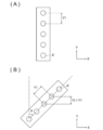
- a row of inkjet nozzles provided in the inkjet unit is arranged in the second direction, the coating material is sequentially discharged along the first direction by the inkjet unit, and the adjustment unit is disposed on the landing surface.
- a third rotating unit configured to rotate the inkjet unit relative to the object to be coated and to incline the inkjet nozzle row with respect to the second direction around an orthogonal third direction axis; Furthermore, the coating apparatus as described in said (5). According to the configuration described in (6) above, since the density of the second direction component of the landing coating material can be increased, it is possible to prevent defects in the plating process.
- the apparatus according to any one of (1) to (6), further including another inkjet unit that ejects the coating material in a direction different from a direction in which the coating material is ejected from the inkjet unit.
- Coating device According to the form as described in said (7), even if it is a to-be-coated object which has a three-dimensional shape, a coating material can be apply
- the above (1) to (1) further comprising: a transport unit that relatively transports the inkjet unit and the object to be coated; and a temperature control unit that is provided in the transport unit and controls the temperature of the object to be coated.
- the coating apparatus according to any one of the above. According to the form described in the above (11), the ink dripping of the masking agent that has landed on the landing surface can be reduced, and the inkjet part and the object to be coated can be transported relatively easily.
- an object to be coated that includes a treated surface subjected to surface treatment and a non-treated surface not subjected to the surface treatment, it is solid only at the non-treated surface and is liquefied by heating.
- a removal apparatus having a cooling removal unit that removes a coating material, which is a heat-meltable paraffin-containing masking agent, from the coating object in a solid state with a refrigerant having a temperature lower than the melting point of the paraffin.
- the masking agent containing paraffin applied to the non-processed surface is easily removed from the object to be coated with the refrigerant having a temperature lower than the melting point of paraffin.
- Masking agent can be removed.
- a cooling side recovery unit that recovers the solid masking agent removed by the cooling removal unit from the refrigerant, and the masking agent recovered by the cooling side recovery unit is the above (1) to (11)
- an object to be coated that includes a treated surface subjected to surface treatment and a non-treated surface not subjected to the surface treatment, it is a solid at room temperature and is liquefied by heating.
- a cooling and removal unit that removes the coating material, which is a heat-meltable masking agent containing paraffin, from the coating object in a solid state with a refrigerant having a temperature lower than the melting point of the paraffin, and the cooling removal unit removes the coating material.
- a removal apparatus comprising: a melting removal unit that melts the coating material remaining on the non-processed surface later with a fluid having a temperature equal to or higher than the melting point of the paraffin, and removes the coating material from the coating object in a liquid state.
- the masking agent containing paraffin applied to the non-processed surface is removed from the coating object in a solid state by a refrigerant having a temperature lower than the melting point of paraffin, and then non-processed.
- the masking agent remaining on the surface is melted by a fluid having a temperature equal to or higher than the melting point of paraffin, and is made into a liquid and removed from the coating object. Therefore, the masking agent can be removed more reliably.
- a cooling-side recovery unit that recovers the solid masking agent removed by the cooling removal unit from the refrigerant, and a melt that is recovered after the liquid masking agent removed by the melting removal unit is made solid.
- a side recovery part, and the masking agent recovered by the cooling side recovery part and the melting side recovery part is reused as the coating material according to any one of (1) to (11) above (14)
- a removing apparatus having a melting and removing unit that melts a coating material, which is a heat-meltable masking agent containing paraffin, with a fluid having a temperature equal to or higher than the melting point of the paraffin, converts the coating material into a liquid, and removes the coating material.
- the masking agent containing paraffin applied to the non-processed surface is melted by a fluid having a temperature equal to or higher than the melting point of paraffin, and is removed from the coating object in a liquid state.
- the masking agent can be easily removed.
- a liquid-side masking agent removed by the melt-removing unit has a melting-side recovery part that is recovered after being solidified, and the masking agent recovered by the melting-side recovery part is the above (1) to (The removal apparatus according to (16), which is reused as the coating material according to any one of (11). According to the form described in (17) above, since the masking agent removed by the melt removal unit can be reused, the usage amount of the coating material can be reduced.
- a coating removal system comprising: the coating apparatus according to any one of (1) to (11) above; and the removing apparatus according to any one of (12) to (17) above. According to the configuration described in (18) above, surface treatment can be performed accurately and easily on a minute region.
- a heat-meltable coating material that is solid at room temperature and is liquefied by heating, wherein the non-coated surface includes a treated surface that is subjected to a surface treatment and a non-treated surface that is not subjected to the surface treatment.
- a coating method for coating only on a processing surface comprising: a supplying step of supplying the melted coating material to an ink jet unit; and a discharging step of discharging the coating material supplied in the supplying step by the ink jet unit Application method.
- the supplying step includes a charging step of charging the solid or liquid coating material into the tank unit, a melting step of melting the solid coating material charged in the charging step, and the melting step (A) a feeding step of sending the coating material melted in step (a) to the ink jet unit; and (a) a melting maintaining step of maintaining a molten state of the coating material in a connecting portion that connects the tank unit and the ink jet unit.
- the coating method as described in 19). According to the configuration described in (20) above, since the solid coating material can be placed on the tank portion, workability is improved.
- the inkjet unit Before the ejection step, the inkjet unit is moved three-dimensionally relative to the application object to adjust the posture, and the position where the application material is applied on the application object is determined.
- a removal method comprising a cooling and removing step of removing a coating material, which is a heat-meltable masking agent containing paraffin, from the object to be coated in a solid state with a refrigerant having a temperature lower than the melting point of the paraffin.
- a coating material which is a heat-meltable masking agent containing paraffin
- the method further comprises a cooling side recovery step of recovering the solid masking agent removed in the cooling removal step from the refrigerant, and the masking agent recovered in the cooling side recovery step is the above (19) to (25)
- the removal method according to (26) above which is reused as the coating material according to any one of (25). According to the form described in (27) above, since the masking agent removed in the cooling removal step can be reused, the amount of coating material used can be reduced.
- an object to be coated that includes a treated surface that is subjected to surface treatment and a non-treated surface that is not subjected to the surface treatment, it is solid only at the non-treated surface and is liquefied by heating.
- the masking agent containing paraffin applied to the non-processed surface is removed from the coating object in a solid state by a refrigerant having a temperature lower than the melting point of paraffin, and then non-processed.
- the masking agent remaining on the surface is melted with a fluid having a temperature equal to or higher than the melting point of paraffin, and is made into a liquid and removed from the coating object. Therefore, the masking agent can be removed more reliably.
- a melting side recovery step, wherein the masking agent recovered by the cooling side recovery step and the melting side recovery step is used as the coating material according to any one of the above (19) to (25) The removal method according to the above (28), which is reused. According to the form described in (29) above, the masking agent removed in the cooling removal step and the masking agent removed in the melt removal step can be reused, so that the amount of coating material used can be reduced.
- an object to be coated that includes a surface to be surface-treated and a non-treated surface not subjected to the surface treatment, it is a solid at room temperature and is liquefied by heating.
- a removal method comprising a melting and removing step of melting a coating material, which is a heat-meltable masking agent containing paraffin, with a fluid having a temperature equal to or higher than the melting point of the paraffin to form a liquid and removing it from the coating object.
- the masking agent containing paraffin applied to the non-processed surface is melted by a fluid having a temperature equal to or higher than the melting point of paraffin, and is removed in a liquid form from the coating object.
- the masking agent can be easily removed.
- the method further includes a melting side recovery step of recovering the liquid masking agent removed in the melting removal step after making the solid, and the masking agent recovered by the melting side recovery step is the above (19
- the removal method according to (30) above which is reused as the coating material according to any one of (1) to (25). According to the form described in (31) above, since the masking agent removed in the melt removal step can be reused, the amount of coating material used can be reduced.
- a coating removal method comprising: the coating method according to any one of (19) to (25) above; and the removal method according to any one of (26) to (31) above. According to the configuration described in (32) above, surface treatment can be performed accurately and easily on a minute region.
- FIG. 9 is a view showing the coating removal system 2 according to Embodiment A of the present invention.
- FIG. 10A is a diagram illustrating a state in which the coating material A is applied to the non-processed surface S2 of the workpiece W by the inkjet unit 120 of the coating apparatus 10 according to Embodiment A, and FIG. It is a figure which shows the state of the to-be-coated object W after application
- the direction in which the workpiece W is conveyed is the X direction (first direction)
- the direction in which the rows of the inkjet nozzles 124 of the inkjet unit 120 are arranged is the Y direction (second direction), the X direction, and the Y direction.
- a direction orthogonal to the direction is defined as a Z direction (third direction).
- the coating removal system 2 includes a coating device 10 and a removal device 70.
- the coating apparatus 10 applies a heat-treatable coating material A, which is solid at room temperature and is liquefied by heating, to a treatment surface S1 on which a surface treatment is performed and a surface treatment. It is the coating device 10 which apply
- the treated surface S1 and the non-treated surface S2 constitute a landing surface S.
- the coating apparatus 10 includes an inkjet unit 120 that discharges the molten coating material A toward the workpiece W, a supply unit 30 that supplies the molten coating material A to the inkjet unit 120, and a coating material that is provided in the supply unit 30. Heating means 31 for melting A.
- the surface treatment refers to modifying the surface of the workpiece W by a chemical or physical method, for example, chemical modification methods such as plating, etching, plating electroforming, surface roughening, polishing, sputtering.
- chemical modification methods such as plating, etching, plating electroforming, surface roughening, polishing, sputtering.
- the physical modification method such as
- the coating material A in this embodiment is a masking agent A ′ containing paraffin.
- the coating material A includes paraffin and, if necessary, a colorant and other additives. The detailed configuration of the coating material A will be described later.
- the coating material A is referred to as the coating material A, and the coating material A after the coating is applied to the coating object W is referred to as a masking agent A ′.
- the coated object W is, for example, a wiring board or an electronic component.
- the wiring board includes a printed wiring board represented by a mother board, a central processing circuit (CPU), a chip set, a ceramic board, a package board represented by a touch panel board, and the like.
- Electronic parts include semiconductor chips, connectors, sockets, and the like.
- These wiring boards and electronic parts are made of glass epoxy materials, polyimide films, polyamide films, polyester films, polytetrafluoroethylene films, polyphenylene sulfide films, polyethylene naphthalate films, liquid crystal polymer films, etc. It is composed of film, BT resin, silicon wafer, glass, liquid crystal film, aramid, ceramic and the like.
- the above-mentioned material is formed by forming a conductive layer such as copper, silver, tin, nickel, and gold, for example, a resin film with a metal thin film in which a metal thin film is formed on a resin film surface such as a polyimide film. May be.
- FIG. 11 is a diagram illustrating a state where the coating material A is discharged from the ink jet unit 120.
- the ink jet unit 120 is pressurized in the ink flow path 121 through which the liquid coating material A flows, the ink pressurizing chamber 123 pressurized by the piezo 122, and the ink pressurizing chamber 123.
- the rows of inkjet nozzles 124 are arranged in only one row in the Y direction. Since the piezo ink jet technique is a known technique, a detailed description thereof will be omitted.
- the inkjet unit 120 may be provided with a heating unit for maintaining the molten state of the coating material A. In addition, a plurality of rows of inkjet nozzles 124 may be provided.
- the temperature of the coating material A at the time of coating is preferably a temperature of melting point + 20 ° C. or higher, more preferably a temperature of melting point + 30 ° C. or higher, from the viewpoint of improving coating properties.
- the upper limit is not particularly limited as long as it is lower than the boiling point of paraffin, but is preferably 180 ° C. or less, more preferably 140 ° C. from the heat resistance aspect of the inkjet unit 120.
- the melting point of the coating material A is more preferably + 50 ° C. or lower.
- the thickness of the masking agent A ′ is not particularly limited, but is preferably 10 ⁇ m to 100 ⁇ m, and more preferably 10 ⁇ m to 50 ⁇ m. If the thickness of the masking agent A ′ is 10 ⁇ m or more, the generation of pinholes can be suppressed. For this reason, in the process immersed in the plating solution mentioned later, the function as a mask can fully be fulfill
- the width in the Y direction of the masking agent A ′ is not particularly limited, and is set according to the pattern to be formed.
- variety can be formed to arbitrary width by connecting the inkjet part 120 in the Y direction.
- the supply unit 30 includes a tank unit 32 into which a solid or liquid coating material A can be charged, a connecting unit 33 that connects the inkjet unit 120 and the tank unit 32, and a molten coating material A in the tank unit 32. And a delivery unit 34 that sends out to the inkjet unit 120 via the connecting unit 33.
- the heating means 31 includes a first heating unit 31A that is provided in the tank unit 32 and melts the coating material A, and a second heating unit 31B that is provided in the connecting unit 33 and maintains the molten state of the coating material A.
- the first heating unit 31A is, for example, a halogen lamp heater, but is not limited thereto.
- the 2nd heating part 31B is a coiled heater provided in the outer periphery of the connection part 33, for example, it is not restricted to this.
- the tank part 32 is not particularly limited as long as it is a material that can withstand the heating of the first heating part 31A, and for example, a heat-resistant acrylic case may be mentioned.
- the connecting portion 33 is not particularly limited as long as it is a material that can withstand the heating of the second heating portion 31B and has flexibility, and includes, for example, a heat-resistant silicon tube.
- the delivery unit 34 is composed of a pump mechanism.
- the coating apparatus 10 further adjusts the posture by moving the inkjet unit 120 with respect to the workpiece W in a three-dimensional manner, and an adjustment unit 140 that can adjust the position where the coating material A is applied on the workpiece W;
- the transport unit 50 transports the workpiece W to the inkjet unit 120 and the temperature control unit 60 provided in the transport unit 50 to control the temperature of the coat W.
- FIG. 12 is a perspective view showing a schematic configuration of the adjustment unit 140.
- the adjustment unit 140 includes a first rotation unit 141 and a second rotation unit that rotate the inkjet unit 120 relative to the workpiece W about axes in the X direction, the Y direction, and the Z direction, respectively.
- a rotation unit 142 and a third rotation unit 143 are included.
- the 1st rotation part 141, the 2nd rotation part 142, and the 3rd rotation part 143 are the same structures, respectively, About the 1st rotation part 141 and the 2nd rotation part 142 for simplicity in FIG. Is omitted.
- the configuration of the third rotating portion 143 will be described with reference to FIG.
- the third rotation unit 143 rotates the inkjet unit 120 with respect to the workpiece W around the Z-direction axis to incline the row of inkjet nozzles 124 with respect to the Y direction.
- the third rotating unit 143 includes a micrometer 431 and a case 432 to which the inkjet unit 120 is fixed.
- the micrometer 431 has a front end portion 431a provided at the front end and a rotating portion 431b provided at the rear end.
- the case 432 is slidably connected to the support portion S5 in the Y direction.
- the inkjet unit 120 is slidable in the Y direction, and the coating material A can be applied to a desired position (non-processed surface S2) of the landing surface S.
- the front end portion 431a is moved back and forth by rotating the rotating portion 431b and pushes the side surface 432a of the case 432. For this reason, the case 432 is rotated around the axis in the Z direction, and the inkjet unit 120 is rotated.
- the rotation unit 431b is rotated by a signal sent from a control unit (not shown) to a servo motor (not shown) connected to the rotation unit 431b.
- the rotating unit 431b may be rotated manually.
- the conveyance unit 50 is a roll-to-roll conveyance unit 50.
- the roll-to-roll method is a method of drawing an object to be coated W that is drawn out from a state in which the object to be coated W is wound on a roll, and is coated on the object to be coated W in the coating apparatus 10 and then wound around a roll again. This means holding and supplying means.
- the temperature control unit 60 is attached to the transport unit 50 and controls the temperature of the workpiece W being transported.
- the temperature control unit 60 is, for example, a halogen heater, but is not limited thereto.
- the temperature of the object to be coated W when being transported by the transport unit 50 is not particularly limited, but is preferably 24 ° C. to 60 ° from the viewpoint of suppressing peeling of the masking agent A ′ due to rapid contraction, and the ink after coating From the viewpoint of improving elongation, the angle is 50 ° to 60 °.
- the upper limit is not particularly limited as long as it is lower than the melting point of the paraffin constituting the coating material A. However, it is preferably 24 ° C. to 50 ° C. in terms of the elongation of the paraffin, and more preferably 24 ° C. 30 ° C. With this configuration, ink dripping can be prevented by appropriately controlling the temperature of the workpiece W.
- the removal device 70 removes the coating material A, which is a masking agent A ′ containing paraffin, applied only to the non-processed surface S2 from the workpiece W while remaining in a solid state by the refrigerant 712 having a temperature lower than the melting point of paraffin.
- a cooling removal unit 71 is provided.
- the coolant 712 is, for example, water, and the cooling removal unit 71 stored in the water tank 711 is configured to remove the paraffin contained in the masking agent A ′ when the coolant 712 having a temperature lower than the melting point of the paraffin contacts the masking agent A ′.
- the masking agent A ′ is removed from the workpiece W by solidifying.
- the masking agent A ′ is removed with pure water.
- the liquid may be acidic, alkaline, or neutral, but if it is acidic or alkaline, it may adversely affect the metal layer formed by surface treatment such as plating or the like. Therefore, when using a liquid, it is preferable that it is neutral. That is, the refrigerant is preferably cold air and / or neutral liquid. More preferably, it is a neutral liquid. As cold air, cooling gas, such as air, nitrogen, and a carbon dioxide, is mentioned.
- the neutral liquid is not particularly limited as long as it is a neutral liquid that does not dissolve paraffin, and a known liquid can be appropriately selected according to the paraffin used.
- ketone solvents such as methyl ethyl ketone, acetone, diethyl ketone, methyl isobutyl ketone, methyl isopropyl ketone, cyclohexanone, 3-heptanone and 4-heptanone; methanol, ethanol, n-propanol, isopropanol, n-butanol, i-butanol, t-butanol, 3-methyl-1-butanol, 1-pentanol, 2-pentanol, n-hexanol, cyclohexanol, 1-heptanol, 1-octanol, 2-octanol, 2-methoxyethanol, allyl alcohol, full Examples include alcohol solvents such as furyl alcohol and phenol. In addition, these can
- the temperature of the refrigerant 712 is not particularly limited as long as it is lower than the melting point of paraffin and can be peeled off by contraction of paraffin. Since the shrinkage ratio of paraffin depends on the melting point of paraffin, it can be appropriately set according to the melting point of paraffin used for the masking agent A ′. Specifically, in order to improve the peelability, it is preferably (melting point of paraffin ⁇ 60) ° C. or less, more preferably (melting point of paraffin ⁇ 70) ° C. or less, and (melting point of paraffin). ⁇ 80) It is more preferable that the temperature is equal to or lower than ° C. For example, the temperature of the refrigerant is preferably 25 ° C.
- the refrigerant temperature is not particularly limited.
- the temperature can be -196 ° C.
- the removing device 70 further includes a cooling side recovery unit 72 that recovers the solid masking agent A ′ removed by the cooling removal unit 71 from the refrigerant, and the masking agent A ′ recovered by the cooling side recovery unit 72 is applied to the coating material A. Reuse as.
- the cooling side recovery unit 72 recovers the masking agent A ′ removed in the cooling removal unit 71 and precipitated or suspended in the water tank 711.
- the cooling side recovery unit 72 is not limited as long as it can withstand the weight of the recovered masking agent A ′ and can recover only the masking agent A ′.
- the masking agent A ′ recovered in the cooling side recovery unit 72 can be reused as the coating material A as it is.
- impurities in the recovered masking agent A ′ for example, metal pieces, metal particles, dust / dust, and the like generated by plating may be removed and reused.
- the recovered masking agent A ′ may be purified and reused as necessary.
- paraffin refers to an alkane having 20 or more carbon atoms (chain saturated hydrocarbon having a general formula of C n H 2n + 2 ). Paraffin has high chemical stability and excellent chemical resistance (alkali resistance and acid resistance) to surface treatment agents such as highly corrosive plating solutions and etching solutions. For this reason, the composition containing paraffin can be used as a masking agent A ′ during surface treatment such as plating or etching. In the surface treatment using the masking agent A ′ containing paraffin, the coating material A in a molten state was applied to the non-treated surface on which the surface treatment of the article to be coated W was not performed (a mask pattern was formed) as described later.
- Paraffin also has the advantage of high safety to the human body, and the handling of the masking agent A ′ is improved by producing the masking agent A ′ using paraffin.
- the paraffin that can be used in the present invention is not particularly limited, and is preferably a chain saturated hydrocarbon having 20 to 80 carbon atoms, and more preferably a chain saturated hydrocarbon having 20 to 40 carbon atoms.
- the paraffin may be linear or branched. Paraffin may be composed of a uniform material, but is usually a mixture of two or more types of chain saturated hydrocarbons (paraffins) having different carbon chains.
- the number average molecular weight Mn of the paraffin is preferably 220 to 480, more preferably 220 to 300, and further preferably 220 to 260.
- the average carbon number of paraffin is preferably 20-40.
- the higher the carbon number the higher the melting point of paraffin. Therefore, by changing the number of carbons contained, the melting point of the paraffin can be set to a desired range, and the adhesion to the workpiece W and the peelability during cooling can be improved.
- the melting point of paraffin varies depending on the application of the coating material A, but paraffin that is solid at normal temperature (25 ° C.) is preferable. More preferably, the melting point of paraffin is 40 ° C or higher, and further 50 ° C or higher. More preferably, it is 60 degreeC or more, Most preferably, it is 65 degreeC or more. Removal of masking agent A ′ and surface treatment (plating treatment, etching treatment) described later must be performed at a temperature lower than the melting point of paraffin. Therefore, in such a case, removal of the masking agent A ′ composed of paraffin and surface treatment can be easily performed, and the selection range of these treatment temperatures is wide, which is preferable.
- the upper limit of the melting point is not particularly limited, but it is preferable that the melting point is 200 ° C. or lower because application of the coating material A including paraffin can be performed under mild conditions.
- the melting point is more preferably 150 ° C. or less, further preferably 100 ° C. or less, and particularly preferably 85 ° C. or less.
- paraffin wax produced by separating and refining from a petroleum vacuum distillation distillate stipulated in JIS K 2235: 2009, or synthetic paraffin derived from petroleum mineral, synthetic wax, and the like.
- synthetic paraffin derived from petroleum mineral, synthetic wax, and the like As a commercial product, Nippon Seiwa Co., Ltd. "PARAFFINWAX" series can be mentioned as a suitable example.
- the coating material A may be composed only of the above paraffin. However, the coating material A may be a masking composition containing paraffin and, if necessary, a colorant and other additives.
- the coating material A preferably contains a colorant. Since paraffin is translucent to white at normal temperature, the visibility of the coating material A applied to the non-treated surface is improved by adding a colorant.
- the colorant is not particularly limited, and conventionally known pigments and / or dyes can be used.
- pigments examples include Pigment Red 3, 5, 19, 22, 31, 38, 43, 48: 1, 48: 2, 48: 3, 48: 4, 48: 5, 49: 1, 53: 1, 57. : 1, 57: 2, 58: 4, 63: 1, 81, 81: 1, 81: 2, 81: 3, 81: 4, 88, 104, 108, 112, 122, 123, 144, 146, 149 166, 168, 169, 170, 177, 178, 179, 184, 185, 208, 216, 226, 257, Pigment Violet 3, 19, 23, 29, 30, 37, 50, 88, Pigment Orange 13, 16 , 20, 36, etc .; Pigment Blue 1, 15, 15: 1, 15: 2, 15: 3, 15: 4, 15: 6, 16, 17-1, 2 27, 28, 29, 36, 60, etc.
- Black pigments such as Pigment Black 7, 28, and 26; white pigments such as Pigment White 6, 18, and 21 can be used according to the purpose.
- the dye is preferably an oil-soluble dye that is substantially insoluble in water.
- the oil-soluble dye means one having a solubility in water at 25 ° C. (mass of dye that can be dissolved in 100 g of water) of 1 g or less, preferably 0.5 g or less, more preferably It is preferably 0.1 g or less.
- pigments and / or dyes may be used alone or as a mixture of two or more.
- the average particle diameter of the colorant particles is preferably 1 to 20 ⁇ m, more preferably 1 to 10 ⁇ m, and more preferably 1 to 5 ⁇ m. More preferably, the thickness is preferably 1 to 2 ⁇ m. This range is preferable because clogging of the inkjet nozzle 124 can be suppressed and storage stability can be maintained.
- the coating material A is a dispersing agent for improving the dispersibility of the colorant, a surfactant for adjusting the surface tension of the coating material A, a viscosity adjusting agent, and adhesion imparting for improving the adhesiveness as necessary.
- Additives of additives such as materials, plasticizers for imparting flexibility, or antioxidants for imparting thermal stability may be included.
- the content of paraffin in the coating material A is preferably 85% by weight or more and less than 100% by weight with respect to the total weight of the coating material A from the viewpoint of sufficiently exhibiting chemical resistance. It is more preferably 90% by weight or more and 99.99% by weight or less from the viewpoint of preventing reaction, and it is 95% by weight or more and 99.99% by weight or less from the point of further preventing chemical reaction with the plating solution. Further preferred.
- the content of the colorant in the coating material A is appropriately selected depending on the purpose of use, but in consideration of the coating property and coloring property of the coating material A, it is 0.01 to 10% by mass with respect to the total weight of the coating material A.
- the content is preferably 0.01 to 5% by mass, more preferably 0.01 to 1% by mass.
- the content of other additives in the coating material A is not particularly limited as long as it does not impair the effects of the present invention, but is usually 0.1 weight relative to the total weight (100 parts by weight) of paraffin and colorant. Part to 10 parts by weight is preferable.
- the coating material A containing a colorant and / or an additive is prepared by using a paraffin in a molten state and a colorant and / or an additive such as a ball mill, a sand mill, an attritor, a roll mill, an agitator, a Henschel mixer, a colloid mill. It can be carried out by mixing using a dispersion device such as an ultrasonic homogenizer, a pearl mill, a wet jet mill, or a paint shaker.
- a dispersion device such as an ultrasonic homogenizer, a pearl mill, a wet jet mill, or a paint shaker.
- the coating material A preferably has a viscosity at 80 ° C. of 5 to 30 mPa ⁇ s. Within such a range, various coating apparatuses and coating methods including an inkjet method can be employed. In general, a higher viscosity is better in terms of preventing ink dripping after ejection, but if the viscosity is too high, the ink does not stretch well, and even if the resolution is increased, it may be difficult to form a uniform coated surface. From this viewpoint, the viscosity is preferably 5 to 20 mPa ⁇ s, and more preferably 8 to 20 mPa ⁇ s. The viscosity of the coating material A can be adjusted to a desired range by adjusting the composition of paraffin (the type and content ratio of the chain saturated hydrocarbon) constituting the coating material A or by adding a viscosity modifier. .
- 100 parts by weight of paraffin wax (melting point: 95 ° C.) and coating material A in which 5 parts by weight of pigment as a colorant are mixed are used.
- the viscosity of the coating material A was measured using a rotary viscometer (for example, TVB-35 manufactured by Toki Sangyo Co., Ltd.), it was 12 mPa ⁇ s at 80 ° C.
- the masking agent A ′ performs a predetermined surface treatment on the workpiece W coated on the non-processing surface S2, and then masks from the non-processing surface S2 of the coating material W. By removing the agent A ′, a predetermined surface treatment is performed on the treatment surface S1 of the workpiece W.
- a predetermined surface treatment is performed on the treatment surface S1 of the workpiece W.
- FIG. 13 is a view showing the plating unit 1 including the coating removal system 2.
- the plating unit 1 includes a coating removal system 2 and a plating immersion unit 3.
- FIG. 14 is a flowchart showing a plating method by the plating unit 1 shown in FIG.
- FIG. 15 is a diagram illustrating a state at the end of each process by the plating unit 1 illustrated in FIG. 13.
- FIG. 15A is an initial state
- FIG. 15B is a drawing of an object to be coated after the discharge process is completed
- FIG. 15C is a plating solution immersion
- the adjustment unit 140 adjusts the posture of the inkjet unit 120 (adjustment process).
- two coating devices 10 that is, two inkjet units 120 (a first inkjet unit 120 and a second inkjet unit 120 ′) are provided.
- the first inkjet unit 120 is configured by the first rotating unit 141 and the second rotating unit 142. Is rotated about the X axis and the Y axis so that the coating material A is discharged in the direction V1, and the second inkjet unit 120 ′ is configured so that the coating material A is discharged in the direction V2. It is rotated around the axis.
- the third rotating unit 143 rotates the inkjet unit 120 relative to the workpiece W by ⁇ ° around the Z axis.
- the row of the ink jet nozzles 124 is inclined by ⁇ ° from the Y direction.
- the pitch between the inkjet nozzles 124 is Y1
- the Y-direction component Y2 of the pitch between the inkjet nozzles 124 after the inclination is Y1 ⁇ cos ⁇ .
- the rows of the inkjet nozzles 124 are provided only in one row, it is easy to calculate the Y-direction component Y2 of the pitch between the inkjet nozzles 124 after the inclination. Since the Y-direction component Y2 of the pitch between the inkjet nozzles 124 after tilting is represented by Y1 ⁇ cos ⁇ , the Y-direction component Y2 of the pitch between the inkjet nozzles 124 can be reduced by bringing the tilt angle ⁇ close to 90 °.
- the coating material A is charged into the tank unit 32, melted, and supplied to the ink jet unit 120 via the connecting unit 33 (supply process). Specifically, the solid or liquid coating material A is charged into the tank unit 32 (charging process). Then, the solid coating material A is heated to 140 ° C. and melted by the first heating unit 31A provided in the tank unit 32 (melting step). The molten state of the coating material A is maintained by the second heating unit 31B provided on the outer periphery of the connecting unit 33 (melting maintaining step), and the coating material A is sent from the tank unit 32 to the inkjet unit 120 by the sending unit 34. (Sending process)
- the coating material A is ejected by the inkjet unit 120, and is applied to the non-processed surface S2 of the workpiece W (ejection process). Specifically, the liquid coating material A supplied via the connecting portion 33 flows through the ink flow path 121 and flows into the ink pressurizing chamber 123. Then, the ink pressurizing chamber 123 is deformed by applying an appropriate voltage from the plurality of piezos 122 to the appropriate piezos 122 so as to be applied only to the non-processed surface S2. Then, the coating material A (120 ° C.) is discharged from the inkjet nozzle 124 and applied to the non-processed surface S2 (see FIG. 15B).
- the workpiece W is immersed in the plating solution. Specifically, the workpiece W in which the masking agent A ′ is applied to the non-treated surface S2 is immersed in the plating solution of the plating immersion portion 3. As a result, the metal layer M is formed on the processing surface S1 of the workpiece W (see FIG. 15C).
- the object to be coated W may be pretreated before being immersed in the plating solution. Examples of the pretreatment include blast treatment, alkali washing, acid washing, water washing, organic solvent washing, cleaning treatment such as bombardment treatment, etching treatment, and formation of a base layer.
- Examples of the constituent material of the metal layer M include Ni, Cu, Ag, Au, Cr, Zn, Sn, Sn—Pb alloy, and the like.
- the thickness of the metal layer M formed by plating is not particularly limited, but is preferably 0.5 ⁇ m or more in order to exhibit sufficient conductivity. On the other hand, the upper limit is not particularly limited.
- the method for the plating treatment is not particularly limited, and for example, treatments such as an electrolytic plating method and an electroless plating method can be performed.
- the temperature of the plating treatment varies depending on the type of plating solution and the plating method (electrolytic plating, electroless plating). Usually, the temperature of the plating solution is 40 to 80 ° C. in the case of electroless plating, 20 to 70 ° C.
- the electrolytic plating temperature is 50 ° C. or higher.
- the electroless plating treatment is often performed at 50 ° C. or higher.
- the temperature is not particularly limited as long as it is a temperature at which the masking agent A ′ can be prevented from melting during the plating treatment, and may be lower than the melting point of the paraffin constituting the masking agent A ′. It is preferable to perform the plating process at a melting point of paraffin of ⁇ 10 ° C. or lower.
- the masking agent A ′ is used using a paraffin having a melting point of the plating treatment temperature (plating solution temperature) +10 to 50 ° C., more preferably the plating treatment temperature (plating solution temperature) +10 to 30 ° C. Constitute. That is, it is particularly preferable to perform the plating treatment at a temperature of the melting point of the paraffin constituting the masking agent A ′ from ⁇ 10 to 50 ° C., more preferably at a temperature of the melting point of paraffin from ⁇ 10 to 30 ° C.
- the masking agent A ′ is removed from the workpiece W (cooling removal step). Specifically, the workpiece W in which the metal layer M is applied to the processing surface S1 and the masking agent A ′ is applied to the non-processing surface S2 is immersed in water in the water tank 711 of the removing device 70. As a result, the masking agent A ′ applied to the non-processing surface S2 is removed from the non-processing surface S2 (see FIG. 15D).
- the immersion time varies depending on the temperature of the liquid, it is usually preferably 30 seconds to 5 minutes, and more preferably 5 minutes to 30 minutes. Moreover, you may add an ultrasonic vibration etc. as needed during immersion.
- S06 it is determined whether the plating process is completed. If it is determined that the plating process has ended (S06: YES), the process ends.
- the masking agent A ′ removed in S05 is recovered by the cooling side recovery unit 72 (cooling side recovery step). Specifically, the solid masking agent A ′ that is removed from the non-treated surface S2 and floats or settles in the water tank 711 is recovered. Then, the recovered masking agent A ′ is put into the tank portion 32 again and reused as the coating material A.
- the coating apparatus 10 since the masking agent can be accurately applied to all the non-processed surfaces S2, the plating solution is not applied to unnecessary portions, and the plating material It can prevent waste.
- the coating removal system 5 which concerns on Bth Embodiment of this invention is demonstrated.
- the present embodiment is different from the A-th embodiment in that the removal device 170 further includes a melt removal unit 81 and a melt side recovery unit 82.
- description of parts common to the coating removal system 2 according to the A embodiment will be omitted, and only features that are unique to the coating removal system 5 according to the present embodiment will be described.
- the coating removal system 5 includes a coating device 10 and a removal device 170 as shown in FIG.
- the removal device 170 includes a cooling removal unit 71, a cooling side recovery unit 72, a melting removal unit 81, and a melting side recovery unit 82. Since the configurations of the cooling removal unit 71 and the cooling side recovery unit 72 are the same as those in the A-th embodiment, detailed description thereof is omitted here.
- the melting removal unit 81 melts the coating material A remaining on the non-processed surface S2 after being removed by the cooling removal unit 71 with the fluid F having a temperature equal to or higher than the melting point of paraffin, and removes the coating material A from the coating W. To do.
- the melt removal unit 81 includes a liquid storage unit 811, a liquid dropping unit 812, a hot air supply unit 813, a mounting unit 814, and a liquid recovery unit 815.
- Liquid storage unit 811 stores liquid F1.
- the liquid storage unit 811 is provided with a heat source (not shown) to control the temperature of the liquid F1.
- the liquid dropping unit 812 drops the liquid F1 on the workpiece W placed on the placement unit 814. By opening the valve V, the liquid dropping unit 812 is supplied with the liquid F1 from the liquid storage unit 811 in which the liquid F1 is stored, and drops the liquid F1.
- the hot air supply unit 813 supplies the hot air F ⁇ b> 2 to the workpiece W placed on the placement unit 814.
- the liquid recovery unit 815 recovers the liquid F1 and the masking agent A ′ melted by the liquid F1.
- Liquid F1 and hot air F2 constitute fluid F.
- the liquid F1 is, for example, warm water. Note that the liquid similar to the refrigerant 712 can be used without being limited thereto. Further, the temperature of the liquid F1 is not particularly limited as long as it is equal to or higher than the melting point of paraffin. Also, the temperature of the hot air F2 is not particularly limited as long as it is equal to or higher than the melting point of paraffin.
- the melting side recovery unit 82 recovers the liquid masking agent A ′ removed by the melting removal unit 81 after making it solid.
- the masking agent A ′ recovered by the melting side recovery unit 82 is reused as the coating material A.
- the melting side recovery unit 82 recovers the masking agent A ′ removed by the melting removal unit 81 and recovered by the liquid recovery unit 815 and precipitated or suspended in the liquid recovery unit 815 after a predetermined time has elapsed.
- the melting side recovery unit 82 is not particularly limited as long as it can withstand the weight of the recovered masking agent A ′ and can recover only the masking agent A ′.
- the masking agent A ′ recovered in the melting side recovery part 82 can be reused as the coating material A as it is.
- impurities in the recovered masking agent A ′ for example, metal pieces, metal particles, dust / dust, and the like generated by plating may be removed and reused.
- the recovered masking agent A ′ may be purified and reused as necessary.
- the masking agent A ′ performs a predetermined surface treatment on the workpiece W coated on the non-processing surface S2, and then masks from the non-processing surface S2 of the coating material W. By removing the agent A ′, a predetermined surface treatment is performed on the treatment surface S1 of the workpiece W.
- a method of performing a plating process on the processing surface S ⁇ b> 1 of the workpiece W as an example will be described. Since steps up to S04 shown in FIG. 14 are the same as those in the A-th embodiment, the steps after S05 will be described.
- the masking agent A ′ is removed from the workpiece W (cooling removal process, melting removal process). Specifically, first, as described in the embodiment A, the cooling removal step is performed.
- FIG. 19 is a diagram of the workpiece W after completion of the cooling removal process. As shown in FIG. 19, the masking agent A ′ remains on the non-processed surface S2 of the workpiece W.
- the workpiece W is taken out from the water tank 711 and the workpiece W is placed on the placement portion 814.
- hot air F2 is supplied from the hot air supply unit 813 to the workpiece W, and the masking agent A ′ remaining on the non-processed surface S2 of the workpiece W is melted.
- the valve V is opened, and the liquid F1 stored in the liquid storage unit 811 is dropped from the liquid dropping unit 812 onto the non-processing surface S2 of the workpiece W.
- the liquid F1 and the masking agent A ′ melted by the liquid F1 are recovered by the liquid recovery unit 815.
- S06 it is determined whether the plating process is completed. If it is determined that the plating process has ended (S06: YES), the process ends.
- the masking agent A ′ removed in S05 is recovered by the cooling side recovery unit 72 and the melting side recovery unit 82 (cooling side recovery step, melting side recovery step). Since the collection method is the same as that in the A-th embodiment, a detailed description is omitted here.
- the coating removal system 6 which concerns on Cth Embodiment of this invention is demonstrated.
- the present embodiment is different from the A and B embodiments in that the removal device 270 includes a melt removal unit 81 and a melt side recovery unit 82.
- the coating removal system 6 includes a non-treated surface S ⁇ b> 2 of a workpiece W including a treated surface S ⁇ b> 1 subjected to surface treatment and a non-treated surface S ⁇ b> 2 not subjected to surface treatment.
- the coating material A which is a heat-meltable, paraffin-containing masking agent A ′ that is solid only at room temperature and is liquefied by heating, is melted with a liquid F1 having a temperature equal to or higher than the melting point of paraffin. It has a melt removal section 81 that is removed from the object to be coated W.
- the coating removal system 6 includes a melting side recovery unit 82 that recovers the liquid masking agent A ′ removed by the melting removal unit 81 after making it solid, and the masking agent A recovered by the melting side recovery unit 82. 'Is reused as the coating material A. Since the configurations of the melting removal unit 81 and the melting side recovery unit 82 are the same as those in the B-th embodiment, detailed description thereof is omitted here.
- the adjustment unit 140 adjusts the posture of the inkjet unit 120 and the coating material A is discharged in a predetermined direction.
- the adjustment unit 140 is not provided, and is discharged in a predetermined direction in advance.
- the inkjet material may be held by a holder fixed to the coating material A and the coating material A may be discharged.
- the delivery unit 34 is configured by a pump mechanism.
- the tank unit 32 above the inkjet unit 120, the molten coating material A flows down from a high place to a low place. It is also possible to use a natural flow mechanism that feeds out.
- two inkjet units 120 are provided.
- the number of inkjet units 120 may be one or three or more.
- the adjustment unit 140 adjusts the posture of the inkjet unit 120 with respect to the workpiece W.
- the adjustment unit 140 may adjust the posture of the coating object W with respect to the inkjet unit 120. Good.
- the surface treatment is performed in the atmosphere. However, even if the coating material A is melted and the surface treatment is performed in the thermostatic bath. Good.
- the plating process is performed as the surface treatment, but other surface treatment such as an etching process may be performed.
- Example 1-1 Formation of mask pattern
- 100 parts by mass of paraffin wax (melting point: 95 ° C.) and 5 parts by mass of pigment as a colorant were mixed to produce a masking agent.
- the viscosity of the masking agent was measured using a rotary viscometer (eg TVB-35 manufactured by Toki Sangyo Co., Ltd.), it was 12 mPa ⁇ s at 80 ° C.
- the substrate was dropped while being kept at 25 ° C. and selectively printed.
- a mask layer (mask pattern) having a thickness of 30 ⁇ m was formed on the substrate.
- Example 1-2 Formation of mask pattern
- a masking agent was prepared in the same manner as in Example 1-1 except that paraffin wax (melting point: 85 ° C.) was used instead of the paraffin wax in Example 1-1.
- the viscosity of the masking agent was measured using a rotary viscometer (for example, TVB-35 manufactured by Toki Sangyo Co., Ltd.), it was 13 mPa ⁇ s at 80 ° C.
- a masking liquid (120 ° C.) in a molten state from an inkjet head of an inkjet apparatus (jeton manufactured by JE International Co., Ltd.) is placed on a substrate having a copper layer having a thickness of 0.5 mm on a polyimide film.
- the substrate was dropped while being kept at 25 ° C. and selectively printed.
- the substrate on which the pattern was printed was heated using a heat block at 90 ° C. for 10 seconds to dissolve the ink and fill the gaps between the dot-shaped inks.
- a mask layer (mask pattern) having a thickness of 15 ⁇ m was formed on the substrate.
- Example 1-3 Formation of mask pattern
- a mask layer (mask pattern) having a thickness of 15 ⁇ m is formed on the substrate in the same manner as in Example 1-2 except that the substrate is not heated after the masking solution is selectively printed. Formed.
- Example 1-4 Formation of mask pattern
- the substrate was dropped while being kept at 40 ° C. using a heat block, and was printed selectively.
- a mask layer (mask pattern) having a thickness of 15 ⁇ m was formed on the substrate.
- FIGS. 5 to 8 Optical micrographs of the mask patterns obtained in Examples 1-1 to 1-4 are shown in FIGS. 5 to 8, respectively.
- FIG. 5 is a photograph of the mask pattern obtained in Example 1-1.
- 6 is an optical micrograph of the mask pattern obtained in Example 1-2,
- A) is an optical micrograph of the mask pattern at the edge portion, and
- B is an optical micrograph of the mask pattern at the line portion. is there.
- FIG. 7 is an optical micrograph of the mask pattern obtained in Example 1-3.
- FIG. 8 is an optical micrograph of the mask pattern obtained in Example 1-4.
- the mask pattern can be formed using the masking agent containing paraffin according to the present invention.
- the mask pattern obtained in Example 1-3 is formed of a dot-shaped masking agent (ink), and there is a gap (groove) between the inks. It is confirmed.
- Example 1-1 (FIG. 5) in which the mask pattern is formed thick
- Example 1-2 (FIG. 6) in which the substrate is heated after the mask pattern is formed, and the substrate is heated when the masking solution is applied.
- no gap (groove) was observed between the inks of the masking agent.
- Example 1-2 FIG. 6
- Example 1-4 in which the substrate was heated during application of the masking liquid
- the mask pattern was thinly formed. However, it is confirmed that fine edges are formed.
- the masking agent containing paraffin according to the present invention is used to heat or keep the substrate at the time of masking coating, or by the simple method of heating the substrate coated with the masking solution after coating the masking solution. Even when the pattern is thinly formed, it is confirmed that the gap (gap) between the inks is reduced, the resolution of the ink dot pitch can be significantly improved, and the fine edge can be formed.
- Example 2-1 Production of surface-treated substrate (etching treatment)]
- (1) Production of masking agent A masking agent was produced in the same manner as in Example 1-1.
- the substrate after immersion was observed, it was confirmed that there was no peeling or dissolution of the mask pattern, and the masking agent was resistant to the acidic solution. Moreover, the copper of the non-mask pattern formation part (copper exposed part) was etched and dissolved.
- the removed masking agent was floating in pure water.
- the floating masking agent was collected and dried.
- the recovered masking agent was heated to 140 ° C. and melted to regenerate the masking agent.
- the regeneration masking agent can be reused as it is.
- Example 2-2 Production of surface-treated substrate (plating treatment)]
- (1) Production of masking agent A masking agent was produced in the same manner as in Example 1-1.
- a masking liquid (120 ° C.) in a molten state is applied from an ink jet head of an ink jet apparatus (jeton manufactured by JE International Co., Ltd.) to a connector frame (substrate structure: a thickness of 5 to 10 ⁇ m on a copper plate)
- the substrate was dropped on the substrate on which the metal pattern was formed by etching and press molding) while maintaining the temperature at 25 ° C., and was printed selectively.
- a mask pattern having a thickness of 30 ⁇ m was formed on the substrate.
- the removed masking agent was floating in pure water.
- the floating masking agent was collected and dried.
- the recovered masking agent was heated to 140 ° C. and melted to regenerate the masking agent.
- the regeneration masking agent can be reused as it is.
Abstract
Description
本発明の一実施形態において、表面処理はめっき処理である。すなわち、本発明の一実施形態によれば、パラフィンを含むマスキング剤を前記パラフィンの融点以上に加熱してマスキング液を作製する工程(マスキング液の作製工程)と、前記マスキング液を基板上にパターニングしてマスクパターンを形成する工程(マスキング液のパターニング工程)と、前記マスクパターンを有する基板をめっき処理して前記マスクパターンの非形成部に金属層を形成する工程(めっき処理工程)と、前記マスクパターンを構成するマスキング剤を、前記パラフィンの融点未満の温度の冷媒によって除去する工程(マスキング剤の除去工程)と、を含む表面処理基材の製造方法が提供される。 [First embodiment]
In one embodiment of the present invention, the surface treatment is a plating treatment. That is, according to one embodiment of the present invention, a masking agent containing paraffin is heated to a temperature equal to or higher than the melting point of the paraffin to prepare a masking solution (masking solution preparation step), and the masking solution is patterned on the substrate. Forming a mask pattern (masking liquid patterning step), plating the substrate having the mask pattern to form a metal layer on the non-mask pattern portion (plating step), And a step of removing the masking agent constituting the mask pattern with a refrigerant having a temperature lower than the melting point of the paraffin (masking agent removing step).
本発明に係るマスキング剤はパラフィンと、必要に応じて着色剤および他の添加剤を含んで構成される。 (Masking agent)
The masking agent according to the present invention comprises paraffin and, if necessary, a colorant and other additives.
本形態では、まず、パラフィンを含むマスキング剤を前記パラフィンの融点以上に加熱してマスキング液を作製する。具体的には、上記パラフィンのみからなるマスキング剤またはパラフィンを含むマスキング組成物としてのマスキング剤を、パラフィンの融点(融点)以上の温度に加熱することによりマスキング液を得る。なお、マスキング組成物を用いる場合、パラフィンを加熱して溶融状態とした後、これに上記着色剤および/またはその他の添加剤を添加して混合分散装置で混合したものをそのままマスキング液として用いてもよい。マスキング剤の加熱手段は特に制限されず、従来公知の加熱装置を用いることができる。例えば、ホットメルトインク印刷装置に付属する加熱溶融機能を備えたインク供給装置を用いてマスキング剤を加熱溶融することができる。加熱溶融の際には、必要に応じて撹拌してもよい。 (1) Masking solution production process (101 in FIG. 1)
In this embodiment, first, a masking agent containing paraffin is heated to a temperature equal to or higher than the melting point of the paraffin to prepare a masking solution. Specifically, a masking liquid is obtained by heating the masking agent which consists of the said paraffin only, or the masking agent as a masking composition containing paraffin to the temperature more than melting | fusing point (melting | fusing point) of paraffin. When using the masking composition, the paraffin is heated to a molten state, and then the above colorant and / or other additives are added to the mixture and mixed with a mixing and dispersing device, and used as a masking solution. Also good. The heating means for the masking agent is not particularly limited, and a conventionally known heating device can be used. For example, the masking agent can be heated and melted using an ink supply device having a heating and melting function attached to the hot melt ink printing apparatus. When heating and melting, stirring may be performed as necessary.
続いて、図2の(2)に示すように、前記マスキング液を基板21上にパターニングしてマスクパターン22を形成する。具体的には、前工程で得られた溶融状態のマスキング液を基板21上に選択的に塗布し乾燥することによってマスクパターン22を形成する。 (2) Masking solution patterning step (102 in FIG. 1)
Subsequently, as shown in FIG. 2B, the masking liquid is patterned on the
次いで、図2の(3)に示すように、上記工程で得たマスクパターン22を有する基板21をめっき液に浸漬して前記マスクパターンの非形成部に金属層23を形成する。 (3) Plating process (103 in FIG. 1)
Next, as shown in FIG. 2 (3), the
次いで、上記工程で得られたマスクパターンを構成するマスキング剤を、前記パラフィンの融点未満の温度の冷媒によって除去する。これにより、図2の(4)に示すように、基板21上にパターン状の金属層23が形成された表面処理基材24が形成される。パラフィンは冷却する際の収縮率が高いため、パラフィンを含むマスキングパターンをパラフィンの融点未満の温度に冷却することで、基板から容易に剥離することができる。本形態のマスキング剤(マスキングパターン)は、マスキング剤の塗布温度、めっき処理温度、およびマスキング剤の除去温度を制御することにより、マスクパターンの優れた密着性および剥離性を達成できる。したがって、従来のめっき処理において使用されるマスキングテープに比べて密着性および剥離性に優れ、メッキ仕上がりの精度が向上しうる。 (4) Masking agent removal step (104 in FIG. 1)
Subsequently, the masking agent which comprises the mask pattern obtained at the said process is removed with the refrigerant | coolant of the temperature below the melting | fusing point of the said paraffin. Thereby, as shown in (4) of FIG. 2, the surface treatment base material 24 in which the patterned
次いで、必要に応じて冷媒によって除去したマスキング剤を回収する。めっき処理後に除去されたマスキング剤はそのまま廃棄されてもよいが、環境負荷を低減する観点から、除去したマスキング剤は回収され、好ましくは、回収したマスキング剤を再利用される。 (5) Masking agent recovery process (105 in FIG. 1)
Next, the masking agent removed by the refrigerant is collected as necessary. Although the masking agent removed after the plating treatment may be discarded as it is, the removed masking agent is recovered from the viewpoint of reducing the environmental load, and preferably, the recovered masking agent is reused.
本発明の一実施形態において、表面処理はエッチング処理である。すなわち、本発明の一実施形態によれば、金属層が表面に形成されてなる基板を準備する工程(基板の準備工程)と、パラフィンを含むマスキング剤を前記パラフィンの融点以上に加熱してマスキング液を作製する工程(マスキング液の作製工程)と、前記金属層上に前記マスキング液をパターニングしてマスクパターンを形成する工程(マスキング液のパターニング工程)と、前記マスクパターンを有する基板をエッチングする工程(エッチング工程)と、前記マスクパターンを構成するマスキング剤を、前記パラフィンの融点未満の温度の冷媒によって除去する工程(マスキング剤の除去工程)と、を含む表面処理基材の製造方法が提供される。 [Second Embodiment]
In one embodiment of the present invention, the surface treatment is an etching treatment. That is, according to one embodiment of the present invention, a step of preparing a substrate on which a metal layer is formed (substrate preparation step), and a masking agent containing paraffin is heated to a temperature equal to or higher than the melting point of the paraffin for masking. A step of preparing a liquid (masking solution preparation step), a step of patterning the masking solution on the metal layer to form a mask pattern (masking solution patterning step), and etching the substrate having the mask pattern. Provided is a method for producing a surface-treated substrate comprising: a step (etching step); and a step of removing the masking agent constituting the mask pattern with a refrigerant having a temperature lower than the melting point of the paraffin (masking agent removing step). Is done.
まず、図4の(1)に示すように、金属層43が表面に形成されてなる基板41を準備する。 (1) Substrate preparation process (201 in FIG. 3)
First, as shown in FIG. 4A, a
続いて、マスキング液を作製する。マスキング液の作製方法は上記めっき処理による表面処理基材の製造方法に係る実施形態における方法と同様であるため、具体的な説明を省略する。 (2) Masking solution preparation process (202 in FIG. 3)
Subsequently, a masking solution is prepared. The method for producing the masking liquid is the same as the method according to the embodiment relating to the method for producing the surface-treated substrate by the plating treatment, and a detailed description thereof will be omitted.
次いで、図4の(2)に示すように、前記マスキング液を金属層43上にパターニングしてマスクパターン42を形成する。マスキング液の具体的なパターニング方法は、基板21に代えて金属層43上にマスキング液をパターニングすることを除き上記めっき処理による表面処理基材の製造方法に係る実施形態における方法と同様であるため、具体的な説明を省略する。 (3) Patterning process of masking solution (203 in FIG. 3)
Next, as shown in FIG. 4 (2), the masking liquid is patterned on the
続いて、図4の(3)に示すように、前記マスクパターン42を有する基板41をエッチングする。 (4) Etching process (204 in FIG. 3)
Subsequently, as shown in FIG. 4C, the
次いで、前記マスクパターン42を構成するマスキング剤を、前記パラフィンの融点未満の温度の冷媒によって除去する。これにより、基板41上にパターン状の金属層43が形成された表面処理基材44が形成される。マスキング剤の除去工程は上記めっき処理による表面処理基材の製造方法に係る実施形態における方法と同様であるため、具体的な説明を省略する。 (5) Masking agent removal step (205 in FIG. 3)
Next, the masking agent constituting the
次いで、必要に応じて冷媒によって除去したマスキング剤を回収する。回収されたマスキング剤は上記めっき処理による表面処理基材の製造方法に係る実施形態と同様に、再利用することができる。当該回収工程の具体的な方法は、上記めっき処理による表面処理基材の製造方法に係る実施形態と同様であるため具体的な説明を省略する。 (6) Masking agent recovery process (206 in FIG. 3)
Next, the masking agent removed by the refrigerant is collected as necessary. The recovered masking agent can be reused in the same manner as in the embodiment relating to the method for producing a surface-treated substrate by the plating process. Since the specific method of the said recovery process is the same as that of the embodiment which concerns on the manufacturing method of the surface treatment base material by the said plating process, specific description is abbreviate | omitted.
本発明においては、上述しためっき処理やエッチング処理などの表面処理を複数回繰り返し、および/または、上述しためっき処理およびエッチング処理などの複数の表面処理を組み合わせて、積層形態のパターンを形成することができる。 [Other Embodiments]
In the present invention, the surface treatment such as the above-described plating treatment or etching treatment is repeated a plurality of times and / or a plurality of surface treatments such as the above-described plating treatment and etching treatment are combined to form a pattern in a laminated form. Can do.
本発明はまた、塗布装置、除去装置及び塗布除去システム並びに塗布方法、除去方法及び塗布除去方法をも提供する。詳細には、本発明は、下記(1)~(32)に記載の態様をも包含する。 [Another embodiment]
The present invention also provides a coating apparatus, a removal apparatus, a coating removal system, a coating method, a removal method, and a coating removal method. Specifically, the present invention includes the embodiments described in the following (1) to (32).
以下、図面を参照して、本発明の第A実施形態を説明する。なお、図面の寸法比率は、説明の都合上、誇張されて実際の比率とは異なる場合がある。 (A embodiment)
Hereinafter, an embodiment A of the present invention will be described with reference to the drawings. In addition, the dimension ratio of drawing is exaggerated on account of description, and may differ from an actual ratio.
図10(A)に示されるように、塗布装置10は、室温で固体であって加熱により液化される熱溶融性の塗布材料Aを、表面処理が施される処理面S1と表面処理が施されない非処理面S2とを含む被塗布物Wのうち非処理面S2にのみ塗布する塗布装置10である。処理面S1と非処理面S2とは着弾面Sを構成する。 (Coating device 10)
As shown in FIG. 10 (A), the
除去装置70は、非処理面S2にのみ塗布された、パラフィンを含むマスキング剤A´である塗布材料Aを、パラフィンの融点未満の温度の冷媒712によって、固体状のまま被塗布物Wから除去する冷却除去部71を有する。冷媒712は例えば水であり、水槽711内に貯蔵されている
冷却除去部71は、パラフィンの融点未満の温度の冷媒712がマスキング剤A´に接することによって、マスキング剤A´に含まれるパラフィンを固化して、被塗布物Wからマスキング剤A´を除去する。 (Removal device 70)
The
以下、本実施形態に係る塗布装置10によって塗布される塗布材料A及び塗布材料Aが塗布される被塗布物Wについて説明する。 (Coating material A)
Hereinafter, the coating material A applied by the

次に、図18を参照して、本発明の第B実施形態に係る塗布除去システム5について説明する。本実施形態は、除去装置170が溶融除去部81及び溶融側回収部82をさらに有する点において、第A実施形態と異なる。以下、第A実施形態に係る塗布除去システム2と共通する部分は説明を省略し、本実施形態に係る塗布除去システム5のみに特徴のある箇所について説明する。 (B embodiment)
Next, with reference to FIG. 18, the
次に、図20を参照して、本発明の第C実施形態に係る塗布除去システム6について説明する。本実施形態は、除去装置270が溶融除去部81及び溶融側回収部82から構成される点において、第A実施形態及び第B実施形態と異なる。 (C. Embodiment)
Next, with reference to FIG. 20, the
上述した実施形態では、調整部140によってインクジェット部120の姿勢を調整して、所定の方向に塗布材料Aが吐出されたが、調整部140が設けられず、予め所定の方向に吐出されるように固定されたホルダーによってインクジェット部が保持されて塗布材料Aが吐出されてもよい。 (Modification example)
In the embodiment described above, the
(1)マスキング剤の作製
パラフィンワックス(融点:95℃)を100質量部、着色剤として顔料を5質量部を混合し、マスキング剤を作製した。マスキング剤の粘度を回転式粘度計(例えば東機産業社製TVB-35等)を用いて測定したところ、80℃において12mPa・sであった。 [Example 1-1: Formation of mask pattern]
(1) Production of masking agent 100 parts by mass of paraffin wax (melting point: 95 ° C.) and 5 parts by mass of pigment as a colorant were mixed to produce a masking agent. When the viscosity of the masking agent was measured using a rotary viscometer (eg TVB-35 manufactured by Toki Sangyo Co., Ltd.), it was 12 mPa · s at 80 ° C.
得られたマスキング剤を、インクジェット装置に付属の加熱溶融機能を備えるインク供給器に投入し、140℃まで加熱して溶融させ、マスキング液を作製した。 (2) Preparation of masking liquid The obtained masking agent was put into an ink supply provided with an ink melting apparatus and provided with a heating and melting function, and heated to 140 ° C. to be melted to prepare a masking liquid.
インクジェット装置(JEインターナショナル株式会社製jeton)のインクジェットヘッドから溶融状態のマスキング液(120℃)を、ポリイミドフィルム上に厚さ0.5mmの銅層を有する基板上に、基板を25℃に保持しながら滴下し、選択的に印刷した。これにより基板上に30μmの厚さのマスク層(マスクパターン)を形成した。 (3) Masking liquid patterning A masking liquid (120 ° C.) in a molten state from an inkjet head of an inkjet apparatus (jeton manufactured by JE International Co., Ltd.) is placed on a substrate having a copper layer having a thickness of 0.5 mm on a polyimide film. The substrate was dropped while being kept at 25 ° C. and selectively printed. As a result, a mask layer (mask pattern) having a thickness of 30 μm was formed on the substrate.
(1)マスキング剤の作製
実施例1-1のパラフィンワックスに代えて、パラフィンワックス(融点:85℃)を使用したこと以外は、実施例1-1と同様にマスキング剤を作製した。マスキング剤の粘度を回転式粘度計(例えば東機産業社製TVB-35等)を用いて測定したところ、80℃において13mPa・sであった。 [Example 1-2: Formation of mask pattern]
(1) Preparation of Masking Agent A masking agent was prepared in the same manner as in Example 1-1 except that paraffin wax (melting point: 85 ° C.) was used instead of the paraffin wax in Example 1-1. When the viscosity of the masking agent was measured using a rotary viscometer (for example, TVB-35 manufactured by Toki Sangyo Co., Ltd.), it was 13 mPa · s at 80 ° C.
次いで、上記で得たマスキング剤を用いて、実施例1-1と同様に、マスキング液を作製した。 (2) Preparation of masking solution Next, using the masking agent obtained above, a masking solution was prepared in the same manner as in Example 1-1.
インクジェット装置(JEインターナショナル株式会社製jeton)のインクジェットヘッドから溶融状態のマスキング液(120℃)を、ポリイミドフィルム上に厚さ0.5mmの銅層を有する基板上に、基板を25℃に保持しながら滴下し、選択的に印刷した。 (3) Masking liquid patterning A masking liquid (120 ° C.) in a molten state from an inkjet head of an inkjet apparatus (jeton manufactured by JE International Co., Ltd.) is placed on a substrate having a copper layer having a thickness of 0.5 mm on a polyimide film. The substrate was dropped while being kept at 25 ° C. and selectively printed.
(1)マスキング剤の作製
実施例1-2と同様にマスキング剤を作製した。 [Example 1-3: Formation of mask pattern]
(1) Production of masking agent A masking agent was produced in the same manner as in Example 1-2.
次いで、上記で得たマスキング剤を用いて、実施例1-1と同様に、マスキング液を作製した。 (2) Preparation of masking solution Next, using the masking agent obtained above, a masking solution was prepared in the same manner as in Example 1-1.
上記マスキング液を選択的に印刷した後に基板の加熱を行わなかったこと以外は実施例1-2と同様にして基板上に15μmの厚さのマスク層(マスクパターン)を形成した。 (3) Patterning of masking solution A mask layer (mask pattern) having a thickness of 15 μm is formed on the substrate in the same manner as in Example 1-2 except that the substrate is not heated after the masking solution is selectively printed. Formed.
(1)マスキング剤の作製
実施例1-2と同様にマスキング剤を作製した。 [Example 1-4: Formation of mask pattern]
(1) Production of masking agent A masking agent was produced in the same manner as in Example 1-2.
次いで、上記で得たマスキング剤を用いて、実施例1-1と同様に、マスキング液を作製した。 (2) Preparation of masking solution Next, using the masking agent obtained above, a masking solution was prepared in the same manner as in Example 1-1.
インクジェット装置(JEインターナショナル株式会社製jeton)のインクジェットヘッドから溶融状態のマスキング液(120℃)を、ポリイミドフィルム上に厚さ0.5mmの銅層を有する基板上に、基板をヒートブロックを用いて40℃に保持しながら滴下し、選択的に印刷した。これにより基板上に15μmの厚さのマスク層(マスクパターン)を形成した。 (3) Masking liquid patterning A masking liquid (120 ° C.) in a molten state from an inkjet head of an inkjet apparatus (jeton manufactured by JE International Co., Ltd.) is placed on a substrate having a copper layer having a thickness of 0.5 mm on a polyimide film. The substrate was dropped while being kept at 40 ° C. using a heat block, and was printed selectively. Thus, a mask layer (mask pattern) having a thickness of 15 μm was formed on the substrate.
実施例1-1~1-4で得たマスクパターンの光学顕微鏡写真をそれぞれ図5~図8に示す。図5は実施例1-1で得たマスクパターンの写真である。図6は実施例1-2で得たマスクパターンの光学顕微鏡写真であり、(A)はエッジ部のマスクパターンの光学顕微鏡写真であり、(B)はライン部のマスクパターンの光学顕微鏡写真である。図7は実施例1-3で得たマスクパターンの光学顕微鏡写真である。図8は実施例1-4で得たマスクパターンの光学顕微鏡写真である。 (Discussion)
Optical micrographs of the mask patterns obtained in Examples 1-1 to 1-4 are shown in FIGS. 5 to 8, respectively. FIG. 5 is a photograph of the mask pattern obtained in Example 1-1. 6 is an optical micrograph of the mask pattern obtained in Example 1-2, (A) is an optical micrograph of the mask pattern at the edge portion, and (B) is an optical micrograph of the mask pattern at the line portion. is there. FIG. 7 is an optical micrograph of the mask pattern obtained in Example 1-3. FIG. 8 is an optical micrograph of the mask pattern obtained in Example 1-4.
(1)マスキング剤の作製
実施例1-1と同様に、マスキング剤を作製した。 [Example 2-1: Production of surface-treated substrate (etching treatment)]
(1) Production of masking agent A masking agent was produced in the same manner as in Example 1-1.
次いで、実施例1-1と同様に、マスキング液を作製した。 (2) Preparation of masking solution Next, a masking solution was prepared in the same manner as in Example 1-1.
得られたマスクパターンを有する基板を50℃の下記塩化第二銅液に10分間浸漬した。 (4) Etching process The board | substrate which has the obtained mask pattern was immersed for 10 minutes in the following cupric chloride liquid of 50 degreeC.

その後、5℃の純水(pH=6~7)が貯溜された水槽内で基板を5分間超音波洗浄し、マスクパターンを構成するマスキング剤を除去した。これにより、銅のパターンを有する表面処理基板が得られた。 (5) Removal and recovery of masking agent Thereafter, the substrate was ultrasonically cleaned for 5 minutes in a water tank storing pure water (pH = 6 to 7) at 5 ° C. to remove the masking agent constituting the mask pattern. As a result, a surface-treated substrate having a copper pattern was obtained.
(1)マスキング剤の作製
実施例1-1と同様に、マスキング剤を作製した。 [Example 2-2: Production of surface-treated substrate (plating treatment)]
(1) Production of masking agent A masking agent was produced in the same manner as in Example 1-1.
次いで、実施例1-1と同様に、マスキング液を作製した。 (2) Preparation of masking solution Next, a masking solution was prepared in the same manner as in Example 1-1.
インクジェット装置(JEインターナショナル株式会社製jeton)のインクジェットヘッドから溶融状態のマスキング液(120℃)を、基板としてのコネクタフレーム(基板の構成:銅板上に厚み5μm~10μmのエッチング及びプレス成型による金属パターンが形成されたもの)上に、基板を25℃に保持しながら滴下し、選択的に印刷した。これにより基板上に30μmの厚さのマスクパターンを形成した。 (3) Masking liquid patterning A masking liquid (120 ° C.) in a molten state is applied from an ink jet head of an ink jet apparatus (jeton manufactured by JE International Co., Ltd.) to a connector frame (substrate structure: a thickness of 5 to 10 μm on a copper plate) The substrate was dropped on the substrate on which the metal pattern was formed by etching and press molding) while maintaining the temperature at 25 ° C., and was printed selectively. As a result, a mask pattern having a thickness of 30 μm was formed on the substrate.
上記でマスクパターンを形成した基板を65℃のめっき液(pH=4、下記表に示す酸性金めっき溶液)中に1時間浸漬し、0.2~1μmの厚さの14K金メッキ層を形成した。 (4) Plating treatment The substrate on which the mask pattern is formed as described above is immersed in a plating solution at 65 ° C. (pH = 4, acidic gold plating solution shown in the following table) for 1 hour, and is 14K having a thickness of 0.2 to 1 μm. A gold plating layer was formed.

その後、5℃の純水(pH=6~7)が貯溜された水槽内で基板を5分間超音波洗浄し、マスクパターンを構成するマスキング剤を除去した。これにより、めっきパターンを有する表面処理基板が得られた。 (5) Removal and recovery of masking agent Thereafter, the substrate was ultrasonically cleaned for 5 minutes in a water tank storing pure water (pH = 6 to 7) at 5 ° C. to remove the masking agent constituting the mask pattern. Thereby, the surface treatment board | substrate which has a plating pattern was obtained.
21、41 基板、
22、42 マスクパターン、
23、43 金属層、
1 めっき処理ユニット、
2、5、6 塗布除去システム、
3 めっき浸漬部、
10 塗布装置、
120、120´ インクジェット部、
30 供給部、
31 加熱手段、
31A 第1加熱部、
31B 第2加熱部、
32 タンク部、
33 連結部、
34 送出部、
140 調整部、
141 第1回動部、
142 第2回動部、
143 第3回動部、
50 搬送部、
60 温度制御部、
70、170、270 除去装置、
71 冷却除去部、
72 冷却側回収部、
81 溶融除去部、
82 溶融側回収部、
A 塗布材料、
A´ マスキング剤、
F 流体、
M 金属層、
S 着弾面、
S1 処理面、
S2 非処理面、
W 被塗布物。 20, 40 surface treatment substrate,
21, 41 substrate,
22, 42 mask pattern,
23, 43 metal layer,
1 Plating unit,
2, 5, 6 coating removal system,
3 plating immersion part,
10 coating device,
120, 120 ′ inkjet section,
30 supply section,
31 heating means,
31A 1st heating part,
31B 2nd heating part,
32 tank section,
33 connecting part,
34 Sending part,
140 adjustment unit,
141 first rotating part,
142 second rotating part,
143 third rotating part,
50 transport section,
60 temperature controller,
70, 170, 270 removal device,
71 Cooling removal part,
72 Cooling side recovery unit,
81 melting removal part,
82 Melting side recovery section,
A coating material,
A 'masking agent,
F fluid,
M metal layer,
S landing surface,
S1 treatment surface,
S2 non-treated surface,
W Workpiece.
Claims (21)
- パラフィンを含むマスキング剤を前記パラフィンの融点以上に加熱してマスキング液を作製する工程と、
前記マスキング液を基板上にパターニングしてマスクパターンを形成する工程と、
前記マスクパターンを有する基板を表面処理する工程と、
前記マスクパターンを構成するマスキング剤を、前記パラフィンの融点未満の温度の冷媒によって除去して表面処理基材を得る工程と、
を含む表面処理基材の製造方法。 A step of heating a masking agent containing paraffin above the melting point of the paraffin to prepare a masking solution;
Patterning the masking liquid on a substrate to form a mask pattern;
Surface-treating a substrate having the mask pattern;
Removing the masking agent constituting the mask pattern with a refrigerant having a temperature lower than the melting point of the paraffin to obtain a surface-treated substrate;
The manufacturing method of the surface treatment base material containing this. - パラフィンを含むマスキング剤を前記パラフィンの融点以上に加熱してマスキング液を作製する工程と、
前記マスキング液を基板上にパターニングしてマスクパターンを形成する工程と、
前記マスクパターンを有する基板をめっき処理して前記マスクパターンの非形成部に金属層を形成する工程と、
前記マスクパターンを構成するマスキング剤を、前記パラフィンの融点未満の温度の冷媒によって除去する工程と、
を含む、請求項1に記載の表面処理基材の製造方法。 A step of heating a masking agent containing paraffin above the melting point of the paraffin to prepare a masking solution;
Patterning the masking liquid on a substrate to form a mask pattern;
Plating the substrate having the mask pattern to form a metal layer on the non-formation portion of the mask pattern;
Removing the masking agent constituting the mask pattern with a refrigerant having a temperature lower than the melting point of the paraffin;
The manufacturing method of the surface treatment base material of Claim 1 containing this. - 金属層が表面に形成されてなる基板を準備する工程と、
パラフィンを含むマスキング剤を前記パラフィンの融点以上に加熱してマスキング液を作製する工程と、
前記金属層上に前記マスキング液をパターニングしてマスクパターンを形成する工程と、
前記マスクパターンを有する基板をエッチングする工程と、
前記マスクパターンを構成するマスキング剤を、前記パラフィンの融点未満の温度の冷媒によって除去する工程と、
を含む、請求項1に記載の表面処理基材の製造方法。 Preparing a substrate having a metal layer formed on the surface;
A step of heating a masking agent containing paraffin above the melting point of the paraffin to prepare a masking solution;
Patterning the masking liquid on the metal layer to form a mask pattern;
Etching the substrate having the mask pattern;
Removing the masking agent constituting the mask pattern with a refrigerant having a temperature lower than the melting point of the paraffin;
The manufacturing method of the surface treatment base material of Claim 1 containing this. - 前記冷媒によって除去したマスキング剤を回収する工程をさらに含む、請求項1~3のいずれか1項に記載の製造方法。 The method according to any one of claims 1 to 3, further comprising a step of recovering the masking agent removed by the refrigerant.
- 前記回収する工程は、前記除去したマスキング剤を前記マスキング剤よりも比重が大きい中性の液体中に浮遊させて回収することを含む、請求項4に記載の製造方法。 The manufacturing method according to claim 4, wherein the collecting step includes collecting the removed masking agent by suspending it in a neutral liquid having a specific gravity greater than that of the masking agent.
- 前記冷媒は中性の液体および/または冷風である、請求項1~5のいずれか1項に記載の製造方法。 The production method according to any one of claims 1 to 5, wherein the refrigerant is a neutral liquid and / or cold air.
- 前記冷媒は水である、請求項6に記載の製造方法。 The manufacturing method according to claim 6, wherein the refrigerant is water.
- 前記冷媒は純水である、請求項7に記載の製造方法。 The manufacturing method according to claim 7, wherein the refrigerant is pure water.
- 前記マスクパターンを形成する工程は、40~50℃に加熱または保温されている基板上に、前記マスキング液を、塗布する工程を含む、請求項1~8のいずれか1項に記載の製造方法。 The manufacturing method according to any one of claims 1 to 8, wherein the step of forming the mask pattern includes a step of applying the masking liquid onto a substrate heated or kept at 40 to 50 ° C. .
- 前記マスクパターンを形成する工程は、前記マスキング液を基板上に塗布する工程と、前記マスキング液が塗布された基板を70~110℃に加熱する工程を含む、請求項1~9のいずれか1項に記載の製造方法。 The step of forming the mask pattern includes a step of applying the masking liquid on the substrate and a step of heating the substrate coated with the masking liquid to 70 to 110 ° C. The production method according to item.
- 前記マスキング剤を除去する工程において、前記マスクパターンを冷却した後に前記パラフィンの融点未満の温度の冷媒によって前記マスキング剤を除去する、請求項1~10のいずれかに記載の製造方法。 The method according to any one of claims 1 to 10, wherein, in the step of removing the masking agent, the masking agent is removed by a coolant having a temperature lower than the melting point of the paraffin after the mask pattern is cooled.
- 前記マスキング液のパターニングをインクジェット方式により行う、請求項1~11のいずれか1項に記載の製造方法。 The manufacturing method according to any one of claims 1 to 11, wherein the masking liquid is patterned by an ink jet method.
- 前記マスキング剤は着色剤をさらに含む、請求項1~12のいずれか1項に記載の製造方法。 The manufacturing method according to any one of claims 1 to 12, wherein the masking agent further contains a colorant.
- パラフィンを含むマスキング剤を前記パラフィンの融点以上に加熱してマスキング液を作製する工程と、
前記マスキング液を基板上にパターニングしてマスクパターンを形成する工程と、
を含むマスクパターン形成方法。 A step of heating a masking agent containing paraffin above the melting point of the paraffin to prepare a masking solution;
Patterning the masking liquid on a substrate to form a mask pattern;
A mask pattern forming method including: - 前記マスクパターンを形成する工程は、40~50℃に加熱または保温されている基板上に、前記マスキング液を、塗布する工程を含む、請求項14に記載のマスクパターン形成方法。 15. The mask pattern forming method according to claim 14, wherein the step of forming the mask pattern includes a step of applying the masking liquid onto a substrate heated or kept at 40 to 50 ° C.
- 前記マスクパターンを形成する工程は、前記マスキング液を基板上に塗布する工程と、前記マスキング液が塗布された基板を70~110℃に加熱する工程を含む、請求項14または15に記載のマスクパターン形成方法。 The mask according to claim 14 or 15, wherein the step of forming the mask pattern includes a step of applying the masking liquid onto a substrate and a step of heating the substrate coated with the masking liquid to 70 to 110 ° C. Pattern formation method.
- パラフィンを含むマスキング剤。 Masking agent containing paraffin.
- 80℃における粘度が5~30mPa・sである、請求項17に記載のマスキング剤。 The masking agent according to claim 17, wherein the viscosity at 80 ° C is 5 to 30 mPa · s.
- さらに着色剤を含む、請求項17または18に記載のマスキング剤。 The masking agent according to claim 17 or 18, further comprising a colorant.
- 前記パラフィンは前記マスキング剤の全重量に対して85重量%以上100重量%未満である、請求項17~19のいずれか1項に記載のマスキング剤。 The masking agent according to any one of claims 17 to 19, wherein the paraffin is 85% by weight or more and less than 100% by weight with respect to the total weight of the masking agent.
- パラフィンのみからなるマスキング剤。 Masking agent consisting only of paraffin.
Priority Applications (4)
| Application Number | Priority Date | Filing Date | Title |
|---|---|---|---|
| CN201380052467.4A CN104704148A (en) | 2012-09-10 | 2013-08-01 | Masking agent, and method for producing surface-treated base |
| KR1020157008864A KR20150054902A (en) | 2012-09-10 | 2013-08-01 | Masking agent and method for producing surface treated base |
| EP13835747.0A EP2894241A4 (en) | 2012-09-10 | 2013-08-01 | Masking agent, and method for producing surface-treated base |
| US14/426,922 US20150225570A1 (en) | 2012-09-10 | 2013-08-01 | Masking agent, and method for producing surface-treated base |
Applications Claiming Priority (2)
| Application Number | Priority Date | Filing Date | Title |
|---|---|---|---|
| JP2012198563A JP5472950B2 (en) | 2012-06-19 | 2012-09-10 | Masking agent and method for producing surface-treated substrate |
| JP2012-198563 | 2012-09-10 |
Publications (1)
| Publication Number | Publication Date |
|---|---|
| WO2014038325A1 true WO2014038325A1 (en) | 2014-03-13 |
Family
ID=50237823
Family Applications (1)
| Application Number | Title | Priority Date | Filing Date |
|---|---|---|---|
| PCT/JP2013/070933 WO2014038325A1 (en) | 2012-09-10 | 2013-08-01 | Masking agent, and method for producing surface-treated base |
Country Status (6)
| Country | Link |
|---|---|
| US (1) | US20150225570A1 (en) |
| EP (1) | EP2894241A4 (en) |
| JP (1) | JP5472950B2 (en) |
| KR (1) | KR20150054902A (en) |
| CN (1) | CN104704148A (en) |
| WO (1) | WO2014038325A1 (en) |
Cited By (2)
| Publication number | Priority date | Publication date | Assignee | Title |
|---|---|---|---|---|
| WO2016128695A1 (en) * | 2015-02-12 | 2016-08-18 | Jet Metal Technologies | Method and device for producing metal patterns on a substrate for decorative and/or functional purposes, manufacture of objects incorporating said production and set of consumables used |
| US20160333480A1 (en) * | 2015-05-13 | 2016-11-17 | Dan Porodo | Metallic alloy coating system and method |
Families Citing this family (10)
| Publication number | Priority date | Publication date | Assignee | Title |
|---|---|---|---|---|
| DE102013108666A1 (en) * | 2013-08-09 | 2015-03-05 | Leonhard Kurz Stiftung & Co. Kg | Method for producing a multilayer body and multilayer body |
| JP6659278B2 (en) * | 2015-09-03 | 2020-03-04 | 日鉄日新製鋼株式会社 | Masking cured film removing device and etching metal plate manufacturing device |
| JP6720978B2 (en) * | 2015-09-30 | 2020-07-08 | 住友金属鉱山株式会社 | Organic coating manufacturing method, conductive substrate manufacturing method, organic coating manufacturing apparatus |
| DE202016008798U1 (en) * | 2015-10-08 | 2019-09-27 | Laird Technologies, Inc. | Selective plated material rolls |
| JP6334500B2 (en) * | 2015-11-19 | 2018-05-30 | 株式会社ジーテクト | Welding method for aluminized steel sheet |
| US10294571B2 (en) | 2015-12-21 | 2019-05-21 | Legal Manufacturing, LLC | Coloration of electroless nickel plating by application of cold bluing solutions |
| JP6760765B2 (en) * | 2016-03-04 | 2020-09-23 | シチズン時計株式会社 | Manufacturing method of electrostatic electromechanical converter |
| JP7058951B2 (en) * | 2017-05-24 | 2022-04-25 | キヤノン株式会社 | Imprinting equipment and manufacturing method of goods |
| CN108811385B (en) * | 2018-06-12 | 2021-04-30 | Oppo广东移动通信有限公司 | Sheet material, preparation method thereof, shell and mobile terminal |
| CN113082839A (en) * | 2021-03-12 | 2021-07-09 | 满洲里达赉湖热电有限公司 | On-line cleaning method for covering filter |
Citations (10)
| Publication number | Priority date | Publication date | Assignee | Title |
|---|---|---|---|---|
| JPS4918277A (en) * | 1972-06-09 | 1974-02-18 | ||
| JPH01184282A (en) * | 1988-01-14 | 1989-07-21 | Nishiyama Stainless Chem Kk | Masking agent |
| JPH0742000A (en) * | 1993-07-30 | 1995-02-10 | Kawasaki Steel Corp | Method for etching metal surface |
| JPH07224395A (en) * | 1994-02-14 | 1995-08-22 | Nishiyama Stainless Chem Kk | Masking agent |
| JPH08144099A (en) * | 1994-11-28 | 1996-06-04 | Kawasaki Steel Corp | Formation of resist pattern on metallic strip surface |
| JP2003119441A (en) | 2001-10-10 | 2003-04-23 | Sekisui Chem Co Ltd | Masking tape for plating |
| JP2004043852A (en) | 2002-07-10 | 2004-02-12 | Agile Technologies Corp | Plating method and connector terminal |
| JP2005349476A (en) * | 2004-06-11 | 2005-12-22 | Rolls Royce Plc | Method for recovering ceramic core |
| JP2011081031A (en) | 2009-10-02 | 2011-04-21 | Asahi Kasei E-Materials Corp | Photosensitive resin composition |
| JP2012198563A (en) | 2012-06-08 | 2012-10-18 | Mitsubishi Electric Corp | Image display panel, display panel control device, and image display device |
Family Cites Families (13)
| Publication number | Priority date | Publication date | Assignee | Title |
|---|---|---|---|---|
| US3310432A (en) * | 1963-07-11 | 1967-03-21 | Corning Glass Works | Method for applying electrical conductors on a smooth vitreous surface and article |
| US3647730A (en) * | 1969-08-27 | 1972-03-07 | Western Electric Co | Masking compositions |
| US4151313A (en) * | 1977-03-11 | 1979-04-24 | Hitachi, Ltd. | Method for production of printed circuits by electroless metal plating employing a solid solution of metal oxides of titanium, nickel, and antimony as a masking material |
| US4432855A (en) * | 1982-09-30 | 1984-02-21 | International Business Machines Corporation | Automated system for laser mask definition for laser enhanced and conventional plating and etching |
| JPH1195442A (en) * | 1997-09-24 | 1999-04-09 | Sharp Corp | Photoresist pattern forming method |
| GB0324947D0 (en) * | 2003-10-25 | 2003-11-26 | Avecia Ltd | Process |
| JP2006207681A (en) * | 2005-01-27 | 2006-08-10 | Ntn Corp | Method for forming dynamic pressure generating part |
| JP2007184539A (en) * | 2005-12-07 | 2007-07-19 | Denso Corp | Method for manufacturing workpiece |
| US7575694B2 (en) * | 2005-12-29 | 2009-08-18 | General Electric Company | Method of selectively stripping a metallic coating |
| CN101808811A (en) * | 2007-09-26 | 2010-08-18 | 富士通株式会社 | Method of embedding insert part |
| EP2157209B1 (en) * | 2008-07-31 | 2014-10-22 | Rohm and Haas Electronic Materials LLC | Inhibiting Background Plating |
| SG169302A1 (en) * | 2009-08-25 | 2011-03-30 | Rohm & Haas Elect Mat | Enhanced method of forming nickel silicides |
| JP5695110B2 (en) * | 2012-06-25 | 2015-04-01 | Jeインターナショナル株式会社 | Removal device, coating removal system, removal method, and coating removal method |
-
2012
- 2012-09-10 JP JP2012198563A patent/JP5472950B2/en not_active Expired - Fee Related
-
2013
- 2013-08-01 CN CN201380052467.4A patent/CN104704148A/en active Pending
- 2013-08-01 WO PCT/JP2013/070933 patent/WO2014038325A1/en active Application Filing
- 2013-08-01 EP EP13835747.0A patent/EP2894241A4/en not_active Withdrawn
- 2013-08-01 US US14/426,922 patent/US20150225570A1/en not_active Abandoned
- 2013-08-01 KR KR1020157008864A patent/KR20150054902A/en not_active Application Discontinuation
Patent Citations (10)
| Publication number | Priority date | Publication date | Assignee | Title |
|---|---|---|---|---|
| JPS4918277A (en) * | 1972-06-09 | 1974-02-18 | ||
| JPH01184282A (en) * | 1988-01-14 | 1989-07-21 | Nishiyama Stainless Chem Kk | Masking agent |
| JPH0742000A (en) * | 1993-07-30 | 1995-02-10 | Kawasaki Steel Corp | Method for etching metal surface |
| JPH07224395A (en) * | 1994-02-14 | 1995-08-22 | Nishiyama Stainless Chem Kk | Masking agent |
| JPH08144099A (en) * | 1994-11-28 | 1996-06-04 | Kawasaki Steel Corp | Formation of resist pattern on metallic strip surface |
| JP2003119441A (en) | 2001-10-10 | 2003-04-23 | Sekisui Chem Co Ltd | Masking tape for plating |
| JP2004043852A (en) | 2002-07-10 | 2004-02-12 | Agile Technologies Corp | Plating method and connector terminal |
| JP2005349476A (en) * | 2004-06-11 | 2005-12-22 | Rolls Royce Plc | Method for recovering ceramic core |
| JP2011081031A (en) | 2009-10-02 | 2011-04-21 | Asahi Kasei E-Materials Corp | Photosensitive resin composition |
| JP2012198563A (en) | 2012-06-08 | 2012-10-18 | Mitsubishi Electric Corp | Image display panel, display panel control device, and image display device |
Non-Patent Citations (1)
| Title |
|---|
| See also references of EP2894241A4 |
Cited By (7)
| Publication number | Priority date | Publication date | Assignee | Title |
|---|---|---|---|---|
| WO2016128695A1 (en) * | 2015-02-12 | 2016-08-18 | Jet Metal Technologies | Method and device for producing metal patterns on a substrate for decorative and/or functional purposes, manufacture of objects incorporating said production and set of consumables used |
| FR3032724A1 (en) * | 2015-02-12 | 2016-08-19 | Jet Metal Tech | METHOD AND DEVICE FOR REALIZING METALLIC PATTERNS ON A SUBSTRATE FOR DECORATIVE AND / OR FUNCTIONAL PURPOSES MANUFACTURING OBJECTS INCORPORATING THIS PRODUCTION AND CONSUMABLE ASSEMBLY USING THE SAME |
| CN107250442A (en) * | 2015-02-12 | 2017-10-13 | 喷射金属技术公司 | For the method and apparatus for the metal pattern that ornamental and/or feature purpose is formed on substrate, the manufacture of the article comprising the formation and consumptive material group used |
| CN107250442B (en) * | 2015-02-12 | 2021-03-09 | 喷射金属技术公司 | Method for forming metal pattern on substrate and consumable set used in same |
| US11168398B2 (en) | 2015-02-12 | 2021-11-09 | Jet Metal Technologies | Method and device for producing metal patterns on a substrate for decorative and/or functional purposes, manufacture of objects incorporating said production and set of consumables used |
| US20160333480A1 (en) * | 2015-05-13 | 2016-11-17 | Dan Porodo | Metallic alloy coating system and method |
| US9752232B2 (en) * | 2015-05-13 | 2017-09-05 | Dan Porodo | Method of electrolessly plating nickel on tubulars |
Also Published As
| Publication number | Publication date |
|---|---|
| EP2894241A4 (en) | 2016-07-20 |
| JP5472950B2 (en) | 2014-04-16 |
| KR20150054902A (en) | 2015-05-20 |
| EP2894241A1 (en) | 2015-07-15 |
| CN104704148A (en) | 2015-06-10 |
| JP2014025142A (en) | 2014-02-06 |
| US20150225570A1 (en) | 2015-08-13 |
Similar Documents
| Publication | Publication Date | Title |
|---|---|---|
| WO2014038325A1 (en) | Masking agent, and method for producing surface-treated base | |
| JP5695110B2 (en) | Removal device, coating removal system, removal method, and coating removal method | |
| TWI420239B (en) | Improved hot melt compositions | |
| TW201345977A (en) | Ink composition for manufacture of high resolution conducting patterns | |
| WO2005007930A1 (en) | Electroless deposition methods and systems | |
| JP2001516805A (en) | Adhesion of substances on surfaces | |
| JP2013541602A (en) | Conductive metal ink composition and method for forming conductive pattern | |
| KR20070081546A (en) | Silver organo-sol ink for forming conductive patterns | |
| US20140261992A1 (en) | Microcavity carrier with image enhancement for laser ablation | |
| JP6577712B2 (en) | Image formation of three-dimensional substrate using transfer film | |
| WO2020003879A1 (en) | Method for producing molded body having metal pattern | |
| JP2004304129A (en) | Pattern forming method by droplet discharge method, and forming method for multilevel interconnection structure | |
| EP3765290B1 (en) | Three-dimensional printing | |
| US7367118B2 (en) | Method for forming metal wires by microdispensing pattern | |
| KR20120061531A (en) | Method and device of forming a metal pattern | |
| JP5569662B1 (en) | Laminate, conductive pattern and electrical circuit | |
| TWI548513B (en) | Laminate and method for manufacturing the same, printed wiring board, and composition for forming underlayer | |
| CN104582332B (en) | A kind of fine-line package substrate and preparation method thereof | |
| JP5733561B2 (en) | Method for producing metallic copper film and printed metallic copper pattern | |
| US20200288578A1 (en) | Base material for printed circuit board and printed circuit board | |
| JP7204195B2 (en) | Plating primer and laminate using the same | |
| JPH0955578A (en) | Sheet applied with powder solder and formation of solder circuit | |
| JPH04162693A (en) | Manufacture of copper plated through hole printed wiring board | |
| JP2023101962A (en) | Etching method of laminate | |
| TWM536674U (en) | Horizontal continuous electroplating equipment for flexible substrates |
Legal Events
| Date | Code | Title | Description |
|---|---|---|---|
| 121 | Ep: the epo has been informed by wipo that ep was designated in this application |
Ref document number: 13835747 Country of ref document: EP Kind code of ref document: A1 |
|
| WWE | Wipo information: entry into national phase |
Ref document number: 14426922 Country of ref document: US |
|
| NENP | Non-entry into the national phase |
Ref country code: DE |
|
| REEP | Request for entry into the european phase |
Ref document number: 2013835747 Country of ref document: EP |
|
| WWE | Wipo information: entry into national phase |
Ref document number: 2013835747 Country of ref document: EP |
|
| ENP | Entry into the national phase |
Ref document number: 20157008864 Country of ref document: KR Kind code of ref document: A |