WO2014033941A1 - 計算機システムおよび計算機システムの制御方法 - Google Patents
計算機システムおよび計算機システムの制御方法 Download PDFInfo
- Publication number
- WO2014033941A1 WO2014033941A1 PCT/JP2012/072292 JP2012072292W WO2014033941A1 WO 2014033941 A1 WO2014033941 A1 WO 2014033941A1 JP 2012072292 W JP2012072292 W JP 2012072292W WO 2014033941 A1 WO2014033941 A1 WO 2014033941A1
- Authority
- WO
- WIPO (PCT)
- Prior art keywords
- calculation
- computer system
- error
- unit
- processor
- Prior art date
- Legal status (The legal status is an assumption and is not a legal conclusion. Google has not performed a legal analysis and makes no representation as to the accuracy of the status listed.)
- Ceased
Links
Images





Classifications
-
- G—PHYSICS
- G06—COMPUTING OR CALCULATING; COUNTING
- G06F—ELECTRIC DIGITAL DATA PROCESSING
- G06F1/00—Details not covered by groups G06F3/00 - G06F13/00 and G06F21/00
- G06F1/26—Power supply means, e.g. regulation thereof
- G06F1/32—Means for saving power
- G06F1/3203—Power management, i.e. event-based initiation of a power-saving mode
- G06F1/3234—Power saving characterised by the action undertaken
- G06F1/3243—Power saving in microcontroller unit
-
- Y—GENERAL TAGGING OF NEW TECHNOLOGICAL DEVELOPMENTS; GENERAL TAGGING OF CROSS-SECTIONAL TECHNOLOGIES SPANNING OVER SEVERAL SECTIONS OF THE IPC; TECHNICAL SUBJECTS COVERED BY FORMER USPC CROSS-REFERENCE ART COLLECTIONS [XRACs] AND DIGESTS
- Y02—TECHNOLOGIES OR APPLICATIONS FOR MITIGATION OR ADAPTATION AGAINST CLIMATE CHANGE
- Y02D—CLIMATE CHANGE MITIGATION TECHNOLOGIES IN INFORMATION AND COMMUNICATION TECHNOLOGIES [ICT], I.E. INFORMATION AND COMMUNICATION TECHNOLOGIES AIMING AT THE REDUCTION OF THEIR OWN ENERGY USE
- Y02D10/00—Energy efficient computing, e.g. low power processors, power management or thermal management
Definitions
- the present invention relates to a computer system, and more particularly to control of power supply voltage or operating frequency.
- Patent Document 1 discloses a technique for setting a power supply voltage, a frequency, and the like based on error characteristics by utilizing the fact that a critical path of a circuit is rarely activated. In the technique disclosed in Patent Document 1, when an error is detected, it is corrected to a correct value by recalculation or the like.
- an object of the present invention is to provide a technique for increasing the width for changing the power supply voltage, the operating frequency, and the like.
- a computer system including a first processor and a second processor
- at least one of an operating frequency and an operating voltage is variable
- a detection module operating on the second processor is an error of the first processor.
- the determination module operating in the second processor determines at least one of the operating frequency or the operating voltage of the first processor, thereby solving the above-described problem.
- FIG. 1 It is a functional block diagram of the computer system which is an Example of this invention. It is an example of the information which the program 102 has. It is a figure which shows the example of the hardware constitutions of the computer system which is an Example of this invention. It is a figure which shows the example of the control area
- FIG. It is a figure which shows the example of the process which inserts the error detection process information 220 and the correction process information 230 in the main calculation process information 205.
- FIG. 1 is a system configuration diagram of a computer system 1001 according to an embodiment of the present invention.
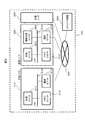
- FIG. 1 is a functional block diagram of a computer system 100 that is an embodiment of the present invention.
- the computer system 100 is a system that outputs a calculation result 106 to an input program 102 and input data 104, and includes a master node 110, one or more worker nodes 120, and a data bus 130.
- the master node 110 includes an error resilience information acquisition unit 111, a calculation allocation unit 112, an error detection / correction method setting unit 113, an FV change determination means setting unit 114, and an error record management unit 115.
- the master node 110 has a function of acquiring, from the program 102 to be executed, information on calculation processing to be solved and error resilience information on calculation error detection means and correction means, and assigns these to the worker node 120. . Further, the master node 110 has a function of performing basic calculation control in parallel processing such as barrier synchronization processing while the worker node 120 is executing calculation processing.
- the error resilience information acquisition unit 111 acquires the main calculation processing information 205 of the application and the calculation error resilience information 201 in the calculation processing from the program 102.
- An example of information included in the program 102 is shown in FIG.
- the program 102 includes main calculation processing information 205 and calculation error tolerance information 201 in the calculation processing.
- the main calculation processing information 205 is a calculation processing program to be solved by the application.
- the calculation error resilience information 201 is information related to the resistance against calculation errors of the application.
- the calculation error resilience information 201 includes error tolerance processing information 210, error detection processing information 220, error correction processing information 230, acceptable error frequency information 240, and FV control processing information 250.
- the error tolerance processing information 210 is information indicating a calculation processing portion resistant to a calculation error in the main calculation processing information 205. Since many of the calculation processing parts that are resistant to calculation errors are repetitive calculations described in a for statement or the like, the programmer can specify the part by a directive or the like.
- the error detection processing information 220 is error detection processing information for detecting a fatal calculation error in the calculation processing portion indicated in the error tolerance processing information 210.
- a fatal calculation error detected by the error detection process is expressed as a user-defined error.
- the error correction processing information 230 is information on error correction processing for correcting a calculation result in which a user-defined error is detected.
- Allowable error frequency information 240 is information on the frequency of user-defined errors that can be accepted by the application. An example is the number of user-defined errors that occur per predetermined calculation step period.
- the FV control processing information 250 is information on control processing of at least one of the operating frequency and the power supply voltage of the calculation unit 121 of the worker node 120. Examples include means for controlling operating frequency and / or power supply voltage based on acceptable error frequency information 240 and the frequency of user-defined errors detected during the calculation.
- the control target is determined by the operation mode setting information included in the FV control processing information 250. In the low power mode, the power supply voltage is controlled with a constant operation frequency, and in the high speed processing mode, the power supply voltage is kept constant. It is possible to control the operating frequency by controlling the operating frequency and lowering the power supply voltage to increase the operating frequency so that the power is constant in the balanced operation mode.
- the calculation process assignment unit 112 assigns the calculation process assigned to each worker node to each worker node 120.
- the error detection / correction means setting unit 113 assigns error detection processing information 220 to the error detection unit 122 of each worker node 120 and assigns error correction processing information 230 to the error correction unit 123 of each worker node 120.
- the FV change determination means setting unit 114 assigns the FV control processing information 250 to the FV change determination unit 124 of each worker node 120.
- the error record management unit 115 records the occurrence status of user-defined errors detected by the error detection unit 122 of each worker node 120.
- the worker node 120 includes a calculation unit 121, an error detection unit 122, an error correction unit 123, an FV change determination unit 124, and an FV control unit 125.
- the calculation unit 121 performs the calculation process assigned by the calculation process assignment unit 112.
- the calculation unit 121 obtains and calculates the data necessary for the calculation from the storage device 340, the input data 104 via the data bus 130 or from another worker node 120, and outputs the calculation result 161 to the error detection unit 122. To do.
- the error detection unit 122 uses the information assigned by the error detection / correction unit setting unit 113 in the detection processing information 220 to detect a user-defined error that is a fatal calculation error in the calculation result of the calculation unit 121. .
- the error detection unit 122 outputs a recalculation request 164 to the calculation unit 121 and a correction request 166 for the calculation result to the error correction unit 123.
- the error detection unit 122 notifies the FV change determination unit 124 that a user-defined error has occurred by a user-defined error occurrence notification 168, and further, an error log related to the occurrence of the user-defined error to the error record management unit 115 of the master node 110.
- Information 165 is output.
- the error correction unit 123 uses the information assigned by the error detection / correction means setting unit 113 in the error correction processing information 230 and uses the calculation result 161 of the calculation unit 121 based on the correction request 166 from the error detection unit 122. To correct.
- the error correction unit 123 outputs the corrected calculation result 167 to the data bus 130.
- the FV change determination unit 124 Based on the information assigned by the FV change determination means setting unit 114 in the FV control processing information 250 and the user-defined error occurrence notification 168 from the error detection unit 122, the FV change determination unit 124 It is decided to change at least one of the operating frequency and the power supply voltage. When the change is determined, the FV change determination unit 124 outputs the set frequency 169 of the operating frequency and the power supply voltage to the FV control unit 125.
- the FV control unit 125 sets the operating frequency and power supply voltage of the calculation unit 121 based on the set amount 169 from the FV change determination unit 124.
- the data bus 130 is a communication path for connecting the master node 110, one or more worker nodes 120, and other external devices.
- FIG. 3 shows an example of the hardware configuration of the computer system 100.
- the computer system 100 includes a calculation node 310, at least one calculation node 320, a network 330, and a storage device 340.
- the calculation node 310 is a calculation node that realizes the function of the master node 110 illustrated in FIG. 1, and includes a calculation unit 311, a memory unit 313, a communication unit 314, and a bus 315.
- the calculation node 310 is an information processing apparatus, for example, a server apparatus.
- the calculation unit 311 is a unit that reads a program from the memory unit 313 and performs calculation, and is realized by a central processing unit (CPU) or the like.
- the memory unit 313 is a unit that stores programs and data, and is realized by a DRAM or the like.
- the communication unit 314 is a unit for performing communication between nodes via the network 330.
- the bus 315 is a communication path for data communication between units in the node such as the calculation unit 311 and the memory unit 313.
- the calculation node 320 is a calculation node that realizes the function of the worker node 120 shown in FIG. 1, and includes a calculation unit 321, an auxiliary calculation unit 322, a memory unit 313, a communication unit 314, and a bus 315.
- the calculation node 320 may include a plurality of calculation units 321 and memory units 313.
- the calculation node 320 is an information processing apparatus, for example, a server apparatus.
- the calculation unit 321 is a calculation unit that realizes the functions of the calculation unit 121 and the FV control unit 125 shown in FIG. 1, and its power supply voltage and operating frequency can be set from the outside.
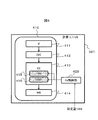
- FIG. 4 shows an example of the control region of the power supply voltage and the operating frequency in the calculation unit 321.
- the computer unit 321 includes a CPU 410 and an FV control unit 420.
- the CPU 410 includes processing blocks that perform an instruction fetch process 411, an instruction decode process 412, an arithmetic process 413, and a write-back process 414.
- the power supply voltage of the arithmetic unit and the storage unit that calculate data not related to program control such as the floating point arithmetic (FPU) unit 415 and the data parallel arithmetic (SIMD) unit 416 that perform the arithmetic processing 413.
- the operating frequency can be set according to the set amount 168 by the FV control unit 420. If an error occurs in a calculation related to program control such as a memory address or pointer calculation, a failure such as a hang-up of the calculation unit 321 may occur.
- the unit 321 by limiting the units that control the power supply voltage or the operating frequency in this way, the calculation is performed when an operation that makes the operation of the CPU 410 unstable, such as reducing the power supply voltage while keeping the operating frequency constant. It is possible to avoid the unit 321 from hanging up.
- the auxiliary calculation unit 322 is a programmable calculation unit realized by a CPU or the like, and realizes the functions of the error detection unit 122, the error correction unit 123, and the FV change determination unit 124 illustrated in FIG. Since the auxiliary calculation unit 322 performs only simple processing, the auxiliary calculation unit 322 can be realized with a calculation unit having processing performance lower than that of the calculation unit 321. In addition, by using the auxiliary calculation unit 322, the functions of the error detection unit 122, the error correction unit 123, and the FV change determination unit 124 are realized by a processor different from the processor that controls the power supply voltage and the operating frequency.
- auxiliary calculation unit 322 is particularly effective for stabilizing the operation of the computer system 100 when the part for controlling the power supply voltage or the operation frequency is not limited in the calculation unit 321.
- the network 330 is a network that connects the computing node 310, one or more computing nodes 320, and the storage apparatus 340, and is configured by a network switch or the like.
- the storage device 340 is used for storing the program 102 and data used by the computer system 100 for calculation.
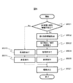
- FIG. 5 shows an operation flowchart of the computer system 100.
- the master node 110 confirms whether or not the program 102 has the calculation error tolerance information 201 in step S501 for determining whether there is calculation error tolerance information.
- the master node 110 divides the main calculation processing information 205 and assigns it to the calculation units 321 of each worker node 120 in the same manner as in a normal parallel computer system (step S510).
- the calculation is executed (step S511), and the result is output (step S521).
- the master node 110 acquires the calculation error tolerance information 201 (step S502), and stores the error detection processing information 220 and the correction processing information 230 as shown in FIG. It inserts into the processing step of the calculation processing information 205 (step S503).
- FIG. 6 shows an example in which an error detection process and an error correction process are inserted between the nth calculation process and the (n + 1) th calculation process in the calculation part indicated in the error tolerance process information 210.
- the n-th calculation process corresponds to the n-th calculation process in the calculation for updating the coordinates of the cluster center position in the K-means clustering algorithm, for example.
- step S503 corresponds to setting the calculation result of the calculation unit 321 to be output via the auxiliary calculation unit 322.
- the insertion positions of the error detection processing information 220 and the error correction processing information 230 are indicated in the main calculation processing information 205 by a directive or the like.
- the master node 110 divides and assigns the processing of the main calculation processing information 205 to the calculation unit 321 of each worker node 120, and further, error detection processing information 220 and error correction processing information to the auxiliary calculation unit 322 of each worker node 120. 230 and FV control processing information 250 are allocated.
- step S505 the computer system 100 executes the calculation process assigned to the worker node 120 in step S504, and outputs the calculation result in step S521.
- the calculation unit 321 of the worker node 120 receives the notification of the start of calculation execution from the master node 110, the calculation unit 121 executed by the calculation unit 321 executes the assigned calculation process, and the calculation result is sent to the auxiliary calculation unit 322. Is transmitted to the error detection unit 122 executed in step S701.
- the error detection unit 122 executed in the auxiliary calculation unit 322 performs error detection processing on the calculation result of the calculation unit 121 executed in the transmitted calculation unit 321 (step S702), and an error is detected. If detected, error correction processing (step S710) and log output processing (step S711) are performed by the error correction unit 123.
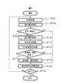
- FIG. 8 is a flowchart corresponding to the error detection process S702 to the log output process S711.
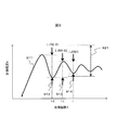
- FIG. 9 shows a transition of the value of the calculation result X at the number of iterations i by a curve 911, and shows an example in which the calculation result X of the iteration calculation converges while oscillating as the number of iterations i increases.
- a calculation error criterion an algorithm that uses the absolute value of the difference between the calculation result of the number of iterations i and the calculation result of the number of iterations i ⁇ 1 (hereinafter referred to as a calculation error criterion)
- the outline of the error detection algorithm will be described first, and then the flowchart of FIG. 8 will be described.
- the calculation result of the calculation unit 121 executed by the calculation unit 321 for the i-th iteration number will be described as X (i).
- ⁇ Xmax MAX ( ⁇ ⁇
- ⁇ Xmax is a larger value of ⁇ times the amount of change 913 at the number of iterations i ⁇ 1 and ⁇ times the amount of change 912 at the number of iterations i ⁇ 2, as shown in Expression (2). It is. ⁇ and ⁇ are values set by the user, and are real numbers of zero or more.
- the upper limit value of the change amount 914 in the iteration number i is the larger value of ⁇ times the change amount 913 in the iteration number i ⁇ 1 and ⁇ times the change amount 912 in the iteration number i ⁇ 2.
- the range of ⁇ X (i) restricted by the upper limit setting is expressed by, for example, a range 921. When
- the two results of the iteration number i-1 and the iteration number i-2 are used because, for example, a calculation error occurs in the iteration number i-1, and
- also becomes very small, and the time required for convergence of the calculation increases. Therefore, on the premise that the probability that a large calculation error will occur twice or more is small, the above problem is solved by employing a larger value as the upper limit value using
- may be set by the user, or may be the maximum value that the variable X can take.
- the error detection algorithm described above makes it possible to avoid calculation errors that have a large impact on applications.
- the error detection unit 122 executed in the auxiliary calculation unit 322 updates the value of the number of iterations i (step S800). Thereafter, the error detection unit 122 calculates the absolute difference between the calculation result X (i ⁇ 1) of the calculation unit 121 executed by the calculation unit 321 at the number of iterations i ⁇ 1 and the calculation result X (i) at the number of iterations i.
- is calculated (step S801), and it is checked whether or not
- step S802 corresponds to the branch in step S703. If the condition of formula (1) is not satisfied in step S802, the error detection unit 121 determines that a user-defined error has occurred. In addition, the FV change determination unit 124 updates the number of occurrences of user-defined errors (step S810), and the frequency is obtained as described later.
- step S710 the error correction unit 167 executed in the auxiliary calculation unit 322 determines that X (i ⁇ 1) when
- log output processing step S711
- error log information 165 such as a user-defined error occurrence status and values before and after correction to the error record management unit 115 of the master node 110.
- the above is an example of processing from error detection processing S702 to log output processing S711. As a result, it is possible to tolerate calculation errors while maintaining the accuracy required by the application. Therefore, it is possible to set a
- the FV change determination unit 124 monitors the frequency of the user-defined error that has occurred in the error detection process (step S702), the user-defined error occurrence frequency, the allowable error frequency information 240, and the FV Based on the operation mode setting information of the control processing information 250, it is determined whether to control the operation frequency or the power supply voltage of the calculation unit 321.
- the FV change determining unit 124 transmits the set amount 169 of the operating frequency or the power supply voltage to the FV control unit 125 of the calculation unit 321 (S714).
- the definition of the user-defined error occurrence frequency includes, for example, the number of times of user-defined error detected per error detection processing N (N is an integer of 1 or more) in step S702, which exceeds the allowable error frequency information 240.
- N is an integer of 1 or more
- the set amount 169 that increases the power supply voltage or decreases the operating frequency is transmitted.
- the FV change determination unit 124 transmits a set amount 169 that reduces the power supply voltage or increases the operating frequency. As a result, the computer system 100 can perform processing at lower power or at higher speed.
- the worker node 120 transmits the calculation result to the other worker nodes 120, notifies the master node 110 of the convergence status information of the calculation result and the completion of the calculation, and the master node 110 performs a synchronization process (step S715).
- the master node 110 determines whether or not the calculation result has converged. If it is determined that the calculation result has converged, the master node 110 ends the calculation (step S716).
- the computer system 100 can set the width for changing the power supply voltage, the frequency, etc. larger than that of the conventional technology, and can achieve a larger power reduction and higher speed.
- a computer system 1001 will be described as an embodiment that is easier to program than the computer system 100 shown in the first embodiment.
- the computer system 1001 uses frequently used processing patterns as templates from the error detection processing information 220, error correction processing information 230, and FV control processing information 250 in the calculation error tolerance information 201 included in the program 102 in the computer system 100. (Or can be expressed as a library) and provided to a programmer as an API (Application Program Interface). With this feature, the programmer can use the functions of the computer system 100 by selecting a processing pattern to be used and specifying its parameters.
- FIG. 10 is an example of a configuration diagram of the computer system 1001 according to the second embodiment.
- the computer system 1001 includes an error forgetting-type calculation template 1020 and a computer system 100, and executes calculation with the program 1010 as an input.
- the error forgetting-type calculation template 1020 includes an error detection process 1021, an error correction process 1022, and an FV control process 1023.
- the error detection process 1021 is, for example, the process of the error detection process information 220 described in the first embodiment, and in this case, ⁇ and ⁇ in Expression (2) can be set as parameters.
- the error correction process 1022 is, for example, the process of the error correction process information 230 described in the first embodiment, and includes recalculation by rollback.
- the error correction processing 1022 can set these correction processing modes as parameters.
- the FV control processing 1023 is, for example, the processing of the FV control processing information 250 described in the first embodiment, and performs control for allowable error frequency information 240 and low power, or control for high speed. Operation mode setting information for specifying such as can be set as a parameter.
- the program 1010 has main calculation processing information 205, error tolerance processing information 210, and parameter information 1011.
- the parameter information 1011 is a parameter of the error detection process 1021, error correction process 1022, and FV control process 1023 of the error forgetting calculation template 1020, and is input to the system as an API argument.
- the computer system 1001 creates calculation error tolerance information 201 using the error forgetting-type calculation template 1020, parameter information 1011, and error tolerance processing information 210, and further adds main calculation processing information 205 to the computer system 100 for the program 102. Enter as.
- the computer system 1001 can set a larger range for changing the power supply voltage and the operating frequency than the prior art, and can achieve a larger power reduction and speedup, and the computer shown in the first embodiment. Higher programmability than the system 100 can be realized.
- 100 Computer system
- 102 Program
- 104 Input data
- 106 Calculation result
- 110 Master node
- 111 Error tolerance information acquisition unit
- 112 Calculation allocation unit
- 113 Error detection / correction method setting unit
- 114 FV change determination means setting unit
- 115 error record management unit
- 120 worker node
- 121 calculation unit
- 122 error detection unit
- 123 error correction unit
- 124 FV change determination unit
- 125 FV control unit
- 130 Data bus 130
- 310 calculation node
- 314 communication unit
- 315 bus
- 320 calculation node
- 322 auxiliary calculation unit
- 330 network
- 340 Storage device.
Landscapes
- Engineering & Computer Science (AREA)
- Theoretical Computer Science (AREA)
- Physics & Mathematics (AREA)
- General Engineering & Computer Science (AREA)
- General Physics & Mathematics (AREA)
- Hardware Redundancy (AREA)
- Debugging And Monitoring (AREA)
- Power Sources (AREA)
- Supply And Distribution Of Alternating Current (AREA)
Description
|ΔX(i)|<ΔXmax・・・式(1)
ΔXmax=MAX(α・|ΔX(i-1)|,β・|ΔX(i-2)|)・・・式(2)
ここで、ΔXmaxは、式(2)で示されるように、反復回数i-1における変化量913のα倍と、反復回数i-2における変化量912のβ倍とのうち、大きい方の値である。αおよびβはユーザが設定する値であり、ゼロ以上の実数である。即ち、反復回数iにおける変化量914の上限値は、反復回数i-1における変化量913のα倍と、反復回数i-2における変化量912のβ倍とのうち、大きい方の値とする。この上限値設定によって制限されるΔX(i)の値域は、例えば、値域921で表現され、|ΔX(i)|が前記上限値を超えた場合(あるいはΔX(i)が値域921の範囲外となった場合とも表現できる)、ユーザ定義エラーが発生したとしてカウントされる。
Claims (12)
- 第1プロセッサと第2プロセッサとを備える計算機システムの制御方法であって、
前記第1プロセッサは、動作周波数または動作電圧の少なくとも一方が可変であり、
前記第2プロセッサで動作する検出モジュールが前記第1プロセッサのエラーを検出し、
前記第2プロセッサで動作する決定モジュールが前記第1プロセッサの動作周波数または動作電圧の少なくとも一方を決定することを特徴とする計算機システムの制御方法。 - 請求項1に記載の計算機システムの制御方法において、
前記決定モジュールが前記第1プロセッサの動作周波数または動作電圧の少なくとも一方を決定する際に、
前記検出モジュールが検出する前記エラーの頻度に基づいて、前記決定モジュールが前記第1プロセッサの動作周波数または動作電圧の少なくとも一方を決定することを特徴とする計算機システムの制御方法。 - 請求項2に記載の計算機システムの制御方法において、
前記頻度は、前記検出モジュールが前記エラーの検出処理を行った回数当りに発生した前記エラーの検出回数であることを特徴とする計算機システムの制御方法。 - 請求項1に記載の計算機システムの制御方法において、
前記計算機システムは、
前記第1プロセッサおよび前記第2プロセッサを含む第1情報処理装置と、
前記第1情報処理装置に前記エラーの検出条件を送信する第2情報処理装置とを備えることを特徴とする計算機システムの制御方法。 - 請求項4に記載の計算機システムの制御方法において、
前記第2情報処理装置は、前記計算機システムに投入されるプログラムから前記検出条件を抽出することを特徴とする計算機システムの制御方法。 - 請求項4に記載の計算機システムの制御方法において、
前記第1情報処理装置および前記第2情報処理装置は、サーバ装置であることを特徴とする計算機システムの制御方法。 - 第1プロセッサと第2プロセッサとを備える計算機システムであって、
前記第1プロセッサは、動作周波数または動作電圧の少なくとも一方が可変であり、
前記第2プロセッサで動作する検出モジュールが前記第1プロセッサのエラーを検出し、
前記第2プロセッサで動作する決定モジュールが前記第1プロセッサの動作周波数または動作電圧の少なくとも一方を決定することを特徴とする計算機システム。 - 請求項7に記載の計算機システムにおいて、
前記検出モジュールが検出する前記エラーの頻度に基づいて、前記決定モジュールが前記第1プロセッサの動作周波数または動作電圧の少なくとも一方を決定することを特徴とする計算機システム。 - 請求項8に記載の計算機システムにおいて、
前記頻度は、前記検出モジュールが前記エラーの検出処理を行った回数当りに発生した前記エラーの検出回数であることを特徴とする計算機システム。 - 請求項7に記載の計算機システムにおいて、
前記計算機システムは、
前記第1プロセッサおよび前記第2プロセッサを含む第1情報処理装置と、
前記第1情報処理装置に前記エラーの検出条件を送信する第2情報処理装置とを備えることを特徴とする計算機システム。 - 請求項10に記載の計算機システムにおいて、
前記第2情報処理装置は、前記計算機システムに投入されるプログラムから前記検出条件を抽出することを特徴とする計算機システム。 - 請求項10に記載の計算機システムにおいて、
前記第1情報処理装置および前記第2情報処理装置は、サーバ装置であることを特徴とする計算機システム。
Priority Applications (3)
| Application Number | Priority Date | Filing Date | Title |
|---|---|---|---|
| JP2014532705A JPWO2014033941A1 (ja) | 2012-09-03 | 2012-09-03 | 計算機システムおよび計算機システムの制御方法 |
| US14/424,145 US20150212570A1 (en) | 2012-09-03 | 2012-09-03 | Computer system and control method for computer system |
| PCT/JP2012/072292 WO2014033941A1 (ja) | 2012-09-03 | 2012-09-03 | 計算機システムおよび計算機システムの制御方法 |
Applications Claiming Priority (1)
| Application Number | Priority Date | Filing Date | Title |
|---|---|---|---|
| PCT/JP2012/072292 WO2014033941A1 (ja) | 2012-09-03 | 2012-09-03 | 計算機システムおよび計算機システムの制御方法 |
Publications (1)
| Publication Number | Publication Date |
|---|---|
| WO2014033941A1 true WO2014033941A1 (ja) | 2014-03-06 |
Family
ID=50182787
Family Applications (1)
| Application Number | Title | Priority Date | Filing Date |
|---|---|---|---|
| PCT/JP2012/072292 Ceased WO2014033941A1 (ja) | 2012-09-03 | 2012-09-03 | 計算機システムおよび計算機システムの制御方法 |
Country Status (3)
| Country | Link |
|---|---|
| US (1) | US20150212570A1 (ja) |
| JP (1) | JPWO2014033941A1 (ja) |
| WO (1) | WO2014033941A1 (ja) |
Cited By (1)
| Publication number | Priority date | Publication date | Assignee | Title |
|---|---|---|---|---|
| JP2019500682A (ja) * | 2015-11-12 | 2019-01-10 | シーメンス アクチエンゲゼルシヤフトSiemens Aktiengesellschaft | マルチコアプロセッサの操作方法 |
Citations (4)
| Publication number | Priority date | Publication date | Assignee | Title |
|---|---|---|---|---|
| WO2008129786A1 (ja) * | 2007-04-09 | 2008-10-30 | Panasonic Corporation | マルチプロセッサ制御装置、その制御方法および集積回路 |
| JP2009025964A (ja) * | 2007-07-18 | 2009-02-05 | Kawasaki Microelectronics Kk | 消費電力の制御方法 |
| JP2009510618A (ja) * | 2005-09-28 | 2009-03-12 | インテル コーポレイション | 多コア・プロセッサによる信頼できるコンピューティング |
| JP2011022957A (ja) * | 2009-07-21 | 2011-02-03 | Nec Corp | 電圧監視システムおよび電圧監視方法 |
Family Cites Families (3)
| Publication number | Priority date | Publication date | Assignee | Title |
|---|---|---|---|---|
| US20060280019A1 (en) * | 2005-06-13 | 2006-12-14 | Burton Edward A | Error based supply regulation |
| US7512842B2 (en) * | 2005-08-29 | 2009-03-31 | Searete Llc | Multi-voltage synchronous systems |
| JP4353990B2 (ja) * | 2007-05-18 | 2009-10-28 | 株式会社半導体理工学研究センター | マルチプロセッサ制御装置 |
-
2012
- 2012-09-03 WO PCT/JP2012/072292 patent/WO2014033941A1/ja not_active Ceased
- 2012-09-03 US US14/424,145 patent/US20150212570A1/en not_active Abandoned
- 2012-09-03 JP JP2014532705A patent/JPWO2014033941A1/ja active Pending
Patent Citations (4)
| Publication number | Priority date | Publication date | Assignee | Title |
|---|---|---|---|---|
| JP2009510618A (ja) * | 2005-09-28 | 2009-03-12 | インテル コーポレイション | 多コア・プロセッサによる信頼できるコンピューティング |
| WO2008129786A1 (ja) * | 2007-04-09 | 2008-10-30 | Panasonic Corporation | マルチプロセッサ制御装置、その制御方法および集積回路 |
| JP2009025964A (ja) * | 2007-07-18 | 2009-02-05 | Kawasaki Microelectronics Kk | 消費電力の制御方法 |
| JP2011022957A (ja) * | 2009-07-21 | 2011-02-03 | Nec Corp | 電圧監視システムおよび電圧監視方法 |
Cited By (1)
| Publication number | Priority date | Publication date | Assignee | Title |
|---|---|---|---|---|
| JP2019500682A (ja) * | 2015-11-12 | 2019-01-10 | シーメンス アクチエンゲゼルシヤフトSiemens Aktiengesellschaft | マルチコアプロセッサの操作方法 |
Also Published As
| Publication number | Publication date |
|---|---|
| US20150212570A1 (en) | 2015-07-30 |
| JPWO2014033941A1 (ja) | 2016-08-08 |
Similar Documents
| Publication | Publication Date | Title |
|---|---|---|
| EP3859528B1 (en) | Method and apparatus for handling memory failure, electronic device and storage medium | |
| Das et al. | Adaptive stream processing using dynamic batch sizing | |
| US20220174122A1 (en) | Fusing and degradation method and apparatus for micro-service, device, and medium | |
| US9176569B2 (en) | Apparatus and method for dynamically adjusting frequency of central processing unit | |
| KR102415867B1 (ko) | 메모리 셀의 결함을 제거하기 위한 메모리 시스템 및 그의 동작 방법 | |
| TWI526820B (zh) | 決定供應至核心的電壓之技術 | |
| US20160342394A1 (en) | Multi-factor entropy sourcing for random number generators | |
| CN103440167A (zh) | Hadoop多作业环境下自学习反馈的任务调度方法 | |
| CN111598247A (zh) | 量子吉布斯态生成方法、装置及电子设备 | |
| US20160179577A1 (en) | Method of Managing the Operation of an Electronic System with a Guaranteed Lifetime | |
| CN111598246A (zh) | 量子吉布斯态生成方法、装置及电子设备 | |
| CN110413414B (zh) | 用于平衡负载的方法、装置、设备和计算机可读存储介质 | |
| WO2014033941A1 (ja) | 計算機システムおよび計算機システムの制御方法 | |
| JP2011180725A (ja) | ハイブリッド並列処理システム、方法、及びプログラム | |
| US8428921B2 (en) | Dynamically adjusting simulation fidelity based on checkpointed fidelity state | |
| CN112445635A (zh) | 数据驱动的自适应检查点优化方法 | |
| Bajaj et al. | UNIPOPT: Univariate projection-based optimization without derivatives | |
| Kazemi et al. | Optimizing the controller placement problem in SDN with uncertain parameters with robust optimization | |
| WO2016087002A1 (en) | Voltage regulator mechanism, electronic device, method and computer program | |
| US9639565B2 (en) | Transaction support using intrusive hash tables | |
| CN107908502B (zh) | 一种基于大型系统拓扑结构的容错节点分配方法 | |
| KR20170037724A (ko) | 복합화력발전기 공급능력 연산 장치, 시스템 및 방법 | |
| US20080195895A1 (en) | Method and Management System for Configuring an Information System | |
| JP7580209B2 (ja) | システム、情報処理方法及びプログラム | |
| KR20220107888A (ko) | 엣지 디바이스를 위한 맥 위치 기반의 내결함성 딥러닝 가속기 방법 및 그 장치 |
Legal Events
| Date | Code | Title | Description |
|---|---|---|---|
| 121 | Ep: the epo has been informed by wipo that ep was designated in this application |
Ref document number: 12883506 Country of ref document: EP Kind code of ref document: A1 |
|
| ENP | Entry into the national phase |
Ref document number: 2014532705 Country of ref document: JP Kind code of ref document: A |
|
| WWE | Wipo information: entry into national phase |
Ref document number: 14424145 Country of ref document: US |
|
| NENP | Non-entry into the national phase |
Ref country code: DE |
|
| 122 | Ep: pct application non-entry in european phase |
Ref document number: 12883506 Country of ref document: EP Kind code of ref document: A1 |