WO2014033775A1 - チューブ接続コネクタ - Google Patents
チューブ接続コネクタ Download PDFInfo
- Publication number
- WO2014033775A1 WO2014033775A1 PCT/JP2012/005449 JP2012005449W WO2014033775A1 WO 2014033775 A1 WO2014033775 A1 WO 2014033775A1 JP 2012005449 W JP2012005449 W JP 2012005449W WO 2014033775 A1 WO2014033775 A1 WO 2014033775A1
- Authority
- WO
- WIPO (PCT)
- Prior art keywords
- tube
- connector
- passage
- inner diameter
- insertion port
- Prior art date
- Legal status (The legal status is an assumption and is not a legal conclusion. Google has not performed a legal analysis and makes no representation as to the accuracy of the status listed.)
- Ceased
Links
Images







Classifications
-
- F—MECHANICAL ENGINEERING; LIGHTING; HEATING; WEAPONS; BLASTING
- F16—ENGINEERING ELEMENTS AND UNITS; GENERAL MEASURES FOR PRODUCING AND MAINTAINING EFFECTIVE FUNCTIONING OF MACHINES OR INSTALLATIONS; THERMAL INSULATION IN GENERAL
- F16L—PIPES; JOINTS OR FITTINGS FOR PIPES; SUPPORTS FOR PIPES, CABLES OR PROTECTIVE TUBING; MEANS FOR THERMAL INSULATION IN GENERAL
- F16L47/00—Connecting arrangements or other fittings specially adapted to be made of plastics or to be used with pipes made of plastics
- F16L47/06—Connecting arrangements or other fittings specially adapted to be made of plastics or to be used with pipes made of plastics with sleeve or socket formed by or in the pipe end
-
- F—MECHANICAL ENGINEERING; LIGHTING; HEATING; WEAPONS; BLASTING
- F16—ENGINEERING ELEMENTS AND UNITS; GENERAL MEASURES FOR PRODUCING AND MAINTAINING EFFECTIVE FUNCTIONING OF MACHINES OR INSTALLATIONS; THERMAL INSULATION IN GENERAL
- F16L—PIPES; JOINTS OR FITTINGS FOR PIPES; SUPPORTS FOR PIPES, CABLES OR PROTECTIVE TUBING; MEANS FOR THERMAL INSULATION IN GENERAL
- F16L37/00—Couplings of the quick-acting type
- F16L37/02—Couplings of the quick-acting type in which the connection is maintained only by friction of the parts being joined
- F16L37/04—Couplings of the quick-acting type in which the connection is maintained only by friction of the parts being joined with an elastic outer part pressing against an inner part by reason of its elasticity
Definitions
- This invention relates to a tube connection connector for connecting piping, and more particularly to a tube connection connector for connecting a minute tube.
- micro tubes with a diameter of about 0.6 mm have been used in various research fields.
- Such a tube is used, for example, in a blood collection device for collecting blood from a mouse.
- Such a tube needs to be piped according to the purpose of use. At that time, a connector for connecting the tubes, a connector for branching the piping, and the like are required.
- Examples of such connectors include Non-Patent Document 1, Non-Patent Document 2, and Non-Patent Document 3.
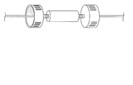
- the conventional connector will be described. As shown in FIG. 16, the conventional connector is configured to be inserted into the inner hole of a cylindrical tube. Such a connector is made of hard plastic or metal and has a distal end having a diameter substantially equal to the inner hole of the tube. When such a connector is used, the connector is covered with the distal end of the tube by inserting the distal end into the tube. At this time, friction is generated between the distal end of the connector and the tube, which prevents the connector from coming off the tube.
- FIG. 1 A connector different from such a configuration is shown in FIG.
- This connector is provided with a part having a through hole through which the tip of the tube is inserted, and is configured to be screwed to the connector body. When the screw is tightened, the through hole of the component is narrowed, and this pressure prevents the tube from coming out of the connector.
- the conventional tube connector has the following problems.
- the connector described with reference to FIG. 16 requires considerable accuracy. This is because it is necessary to process the distal end of the connector so that the inner diameter of the tube to be connected is small and the tube can be inserted and appropriate friction is generated between the tube. Under such circumstances, the tube connector is inevitably expensive, and is not suitable for disposable one after another.
- the connector is used every time the tube is piped.
- the liquid passage inside the connector is fine, and it is difficult to clean it efficiently. Because of such circumstances, the conventional configuration tends to cause contamination that hinders the experiment.
- the connector with the conventional configuration is limited in the tubes that can be connected.
- a tube having an inner diameter of 0.5 mm cannot be connected to a tube connector having an inner diameter of 0.5 mm. This is because this connector is manufactured with considerable accuracy so that a tube having an inner diameter of 0.5 mm can be connected.
- FIG. 17 is expensive because the connector described with reference to FIG. Further, since the connector of FIG. 17 has a mechanism in which a tube is tightened by screwing parts into the main body, it is not suitable for connecting a tube made of a soft material. In addition, since the configuration of FIG. 17 includes a plurality of members, the liquid passage in the connector is lengthened accordingly. Then, a large amount of liquid is required to fill the inside of the connector, and the dead volume increases.
- Non-Patent Document 1 is inexpensive, but generally has a lineup with an inner diameter of 1.5 mm or more, so it cannot be used for tubes smaller than that.
- the present invention has been made in view of such circumstances, and an object of the present invention is to provide an inexpensive and easy-to-use tube connection connector that can handle ultra-fine tubes.
- the tube connection connector according to the present invention is composed of an elastic member in which an insertion port for inserting a tube from the tip and a passage connecting the plurality of insertion ports is formed, and the outer diameter of the tube into which the inner diameter of the passage is inserted. It is characterized by being smaller.
- the tube connector of the structure of the present invention is of a type in which a tube is inserted into a passage.
- the inner diameter of the passage of the present invention is set to be smaller than the outer diameter of the tube.
- the connector is formed of an elastic member. Therefore, when trying to insert the tube into the passage, the tip of the tube advances in the passage while expanding the passage accordingly. As a result, the tube is connected to the connector.
- the correspondence between the outer diameter of the tube and the inner diameter of the passage may not be so strict.
- the passage is wider. As a result, the tube can enter the passage without difficulty even if it is thick.
- the connector Compared to this, according to the conventional configuration, the connector must be manufactured with high accuracy or configured with many parts.
- the outer diameter of the tube that can be connected is also strictly determined.
- the connector can be easily manufactured, and high accuracy is not required and many parts are not required.
- the outer diameter of the tube which can be connected is various. Therefore, according to the present invention, an easy-to-use connector can be provided.
- the connector can be easily made disposable because it can be manufactured at low cost. This is advantageous in that contamination can be prevented in a blood collection situation where blood is stuck inside the connector when the connector is used.
- the elastic member is repelled when the passage is expanded to the tube inserted from the insertion port, and a force for reducing the diameter is applied to the tube.
- both ends of the passage are provided with tapered portions that gradually increase in inner diameter from the center of the passage toward the insertion port.
- the inner diameter of the passage located on the side far from the insertion port is smaller than the inner diameter of the passage located on the side closer to the insertion port.
- the above-described configuration shows a more specific configuration of the present invention. If the inner diameter of the passage located on the side far from the insertion port is smaller than the inner diameter of the passage located on the side closer to the insertion port, the inner diameter of the passage located on the side closer to the insertion port is made sufficiently large, Easy to insert. Moreover, the internal diameter of the channel
- the passage may be configured to communicate two insertion ports.
- the passage may be configured to connect three or more insertion ports and branch the fluid.
- the connector is made of an elastic member, and the inner diameter of the passage is set to be smaller than the outer diameter of the tube. Therefore, when trying to insert the tube into the passage, the tip of the tube advances in the passage while expanding the passage accordingly.
- the connector can be easily manufactured, and high accuracy is not required and many parts are not required.
- tubes having various outer diameters can be connected. As a result, an inexpensive and easy-to-use connector can be provided.
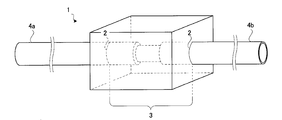
- FIG. 1 is a perspective view illustrating an overall configuration of a connector according to Embodiment 1.
- FIG. It is a perspective view explaining the use condition of the connector which concerns on Example 1.
- FIG. It is sectional drawing explaining a mode that a tube is inserted in the connector which concerns on Example 1.
- FIG. It is sectional drawing explaining a mode that a tube is inserted in the connector which concerns on Example 1.
- FIG. It is sectional drawing explaining a mode that a tube is inserted in the connector which concerns on Example 1.
- FIG. It is sectional drawing explaining a mode that a tube is inserted in the connector which concerns on Example 1.
- FIG. FIG. 6 is a perspective view for explaining the method for manufacturing the connector according to the first embodiment.
- FIG. 6 is a perspective view for explaining the method for manufacturing the connector according to the first embodiment.
- FIG. 6 is a perspective view for explaining the method for manufacturing the connector according to the first embodiment.
- FIG. 6 is a perspective view for explaining the method for manufacturing the connector according to the first embodiment.
- FIG. 6 is a perspective view for explaining the method for manufacturing the connector according to the first embodiment.
- FIG. 6 is a perspective view illustrating the overall configuration of a connector according to a second embodiment. It is sectional drawing explaining one modification of this invention. It is sectional drawing explaining one modification of this invention. It is sectional drawing explaining one modification of this invention. It is sectional drawing explaining one modification of this invention. It is sectional drawing explaining one modification of this invention. It is a schematic diagram explaining the connector of a conventional structure. It is a schematic diagram explaining the connector of a conventional structure.
- This tube connection connector is a joint used when connecting a flexible micro tube having a cylindrical shape.
- This tube connection connector is provided for the purpose of connecting, extending, or branching the tubes.
- the tube to be connected is an ultrathin tube having an inner diameter of less than 1.5 mm, for example.
- the connector 1 is made of a rectangular parallelepiped member as shown in FIG.
- the rectangular parallelepiped member is made of an elastic material such as PDMS (Polydimethylsiloxane) resin. Therefore, when the connector 1 is pinched with a finger, the connector 1 is deformed so that the thickness in the pinching direction is reduced. When the force applied to the connector 1 is released, the connector 1 returns to the shape before being pinched.
- the connector 1 corresponds to the tube connection connector in the present invention.
- the connector 1 has a through hole.
- a two-dimensional hole appearing on the surface of the member of the through hole is referred to as an insertion port 2, and a three-dimensional portion formed so as to connect the two insertion ports 2 of the through hole is defined as a passage 3. I will call it.
- the passage 3 is located inside the member. Since the through hole provided in the connector 1 penetrates from the surface on one side to the surface on the other side of the member, there are two insertion ports 2 for each connector.
- the through-hole is composed of two insertion ports 2 and one passage 3. That is, the connector 1 is composed of an elastic member in which an insertion port 2 for inserting the tube 4 from the tip and a passage 3 for connecting the plurality of insertion ports 2 are formed.
- Passage 3 is a cylindrical hole. Therefore, the thickness of the passage 3 can be evaluated by the inner diameter.
- the inner diameter of the passage 3 is the diameter of the section of the passage 3 that appears on the cut surface when the connector 1 is cut along a plane orthogonal to the direction in which the passage 3 extends (the direction from one insertion port 2 to the other insertion port). That is.
- the inner diameter of the passage 3 is, for example, 0.5 mm regardless of the portion. Further, the inner diameter of the insertion port 2 is 0.5 mm which is the same as the inner diameter of the passage 3.
- FIG. 2 shows a state in which the tubes 4 a and 4 b are inserted into the connector 1.
- the tube 4a is inserted into one of the insertion ports 2 of the connector 1.
- the outside of the tube 4 a inserted into the connector 1 is in contact with the inner wall of the passage 3 on the side of one insertion port 2.
- the outside of the tube 4 b inserted into the connector 1 is in contact with the inner wall of the passage 3 on the other insertion port 2 side.
- the tubes 4 a and 4 b are not inserted up to the deepest position of the passage 3. However, the tubes 4a and 4b may be inserted deeply until the tip of the tube 4a contacts the tip of the tube 4b.
- the outer diameter of the tube 4 represents the thickness of the tube, and is the diameter of the outer wall of the tube in the direction orthogonal to the direction in which the cylindrical tube extends.
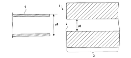
- FIG. 3 shows the tube 4 and the connector 1 before being inserted from the insertion port 2.
- the outer diameter d4 of the tube 4 is 0.6 mm, for example.
- the inner diameter d3 of the passage 3 provided in the connector 1 is 0.5 mm as described above.
- the inner diameter d3 of the passage 3 in the present invention is smaller than the outer diameter d4 of the tube 4 to be inserted.
- the inner diameter of the insertion port 2 is also smaller than the outer diameter d4 of the tube 4.
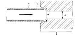
- the connector 1 is made of an elastic member. Therefore, when the tube 4 is inserted into the connector 1 from the insertion port 2, the connector 1 is deformed so that the inner diameter of the insertion port 2 is expanded as shown in FIG. As a result, the insertion port 2 passes the tip of the tube 4.
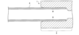
- the deformed connector 1 tries to return to the original shape before the deformation. That is, the elastic member constituting the connector 1 is repelled when the passage 3 is expanded to the tube 4 inserted from the insertion port 2, and applies a force to the tube 4 to reduce the diameter of the tube 4.
- This force is represented by a dotted arrow in FIG.
- This force is a force generated at the interface between the connector 1 and the tube 4 and is a force that increases friction between the connector 1 and the tube 4. Therefore, the connector 1 reliably holds the tip of the inserted tube 4.
- the connector 1 that can reliably hold the tip of the tube 4 while having a simple configuration.
- FIG. 6 illustrates this effect.
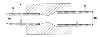
- two tubes 4c and 4d having different outer diameters are inserted into the insertion ports 2 of the connector 1 and the tubes 4c and 4d are connected to each other.
- Both the outer diameter d4c of the tube 4c and the outer diameter d4d of the tube 4d are larger than the inner diameter d3 of the passage 3. Therefore, the tips of any of the tubes 4c and 4d are held by the connector 1 on the same principle as described with reference to FIGS.
- ⁇ Manufacturing method of connector Method of mass production> Next, a method for mass-producing the connector 1 will be described.
- a mold shown in FIG. 8 is prepared. This mold is provided with a rectangular parallelepiped recess. In this mold, linear wires arranged in parallel to each other are provided so as to pass through the recesses.
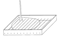
- This recess is filled with a mixture of a main material and a curing agent as a raw material of the elastic body as shown in FIG.
- the main material is a liquid silicone resin having a low crosslinking rate
- the curing agent contains a crosslinking agent for appropriate crosslinking reaction.
- the elastic elastic material that is in a liquid state spreads throughout the recessed area except for the wire portion. Thus, the wire is in a state of sinking in the elastic material before curing.
- the wire is pulled out from the mold as shown in FIG. Since the curing agent is changed to an elastic body by curing, the wire is easily pulled out. The portion from which the wire is removed becomes a cylindrical cavity provided inside the elastic body, and will become the passage 3 in the future.
- the elastic body is pulled out of the mold and cut into a lattice shape as shown by the dotted lines in FIG. Then, the connector 1 described in FIG. 1 is mass-produced.
- the connector 1 having the configuration of the present invention is of a type in which the tube 4 is inserted into the passage 3.
- the inner diameter d3 of the passage 3 of the present invention is set to be smaller than the outer diameter d4 of the tube 4.
- the connector 1 is formed of an elastic member. Therefore, when trying to insert the tube 4 into the passage 3, the tip of the tube 4 advances in the passage while expanding the passage 3 accordingly. As a result, the tube 4 is connected to the connector 1.
- the correspondence between the outer diameter of the tube 4 and the inner diameter of the passage 3 may not be so strict.
- the passage 3 is more widely expanded. As a result, the tube 4 can enter the passage 3 without difficulty even if it is thick.
- the connector 1 Compared to this, according to the conventional configuration, the connector 1 must be manufactured with high accuracy or consist of many parts. Further, the outer diameter of the tube 4 that can be connected is also strictly determined. However, according to the configuration of the present invention, the connector 1 can be easily manufactured, and high accuracy is not required and many parts are not required. Furthermore, the outer diameter of the tube 4 which can be connected is various. Therefore, according to the present invention, an easy-to-use connector 1 can be provided.
- the connector 1 can be easily made disposable because it can be manufactured at low cost. This is advantageous in that contamination can be prevented in the blood collection scene where blood is stuck inside the connector when the connector 1 is used.
- the tube 4 when the tube 4 is inserted into the passage 3, pressure is applied to the tube 4 so that the passage 3 returns to its original shape, so that a sufficiently strong friction is generated between the tube 4 and the connector 1. Will occur. Therefore, according to the connector 1 of the present invention, the tube 4 is not easily detached.
- the configuration of the connector 1 according to the second embodiment is similar to that of the first embodiment.
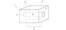
- the connector 1 according to the second embodiment is different from the first embodiment in that tapered portions 5 are provided at both ends of the passage 3 as shown in FIG.
- the tapered portion 5 is formed such that the inner diameter gradually increases from the center 3 c of the passage 3 toward the insertion port 2.
- the tapered portion 5 is a portion provided by cutting the elastic member after the passage 3 is formed, and the inner diameter of this portion does not necessarily need to be smaller than the outer diameter of the tube 4 to be inserted.
- the inner diameter of the insertion port 2 and the inner diameter of the passage 3 are different.
- Example 2 can also be expressed as an elastic member in which a tapered portion 5 into which the tube 4 is inserted from the distal end and a passage connecting the plurality of tapered portions 5 are formed.
- the connector 1 according to the second embodiment is provided with the tapered portions 5 that gradually increase in inner diameter from the center of the passage 3 toward the insertion port 2 at both ends of the passage 3. In this way, since the insertion port 2 is wider than that in the case of the first embodiment, the connector 1 into which the tube 4 can be easily inserted can be provided.
- the configuration of the present invention is not limited to the above-described configuration, and can be modified as follows.
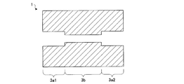
- the inner diameter of the passage 3 is constant, but the present invention is not limited to this configuration. That is, the inner diameter of the passage 3 may be partially changed as shown in FIG. In the example of FIG. 13, the passage 3 is divided into three regions, two regions 3 a 1 and 3 a 2 on the side close to the two insertion ports 2 and a region 3 b far from the insertion port 2, and the inner diameters of the regions 3 a 1 and 3 a 2 Is larger than the inner diameter of the region 3b. That is, in this modification, the inner diameter of the passage 3 located on the side far from the insertion port 2 is smaller than the inner diameter of the passage 3 located on the side closer to the insertion port 2. However, the inner diameters of the regions 3a1 and 3a2 are set smaller than the outer diameter of the tube 4 to be inserted.
- the insertion port 2 is widened and the tube 4 can be easily inserted. Further, since the inner diameter of the region 3b is sufficiently small, the dead volume of the liquid flowing through the connector 1 can be reduced as much as possible.
- the passage 3 is linear, but the configuration of the present invention is not limited to this configuration. As shown in FIG. 14, the passage 3 may be L-shaped.
- the passage 3 is linear, but the configuration of the present invention is not limited to this configuration.
- the passage 3 may be branched.
- a branching method for example, a ⁇ shape as shown on the left side of FIG. 15 or a T shape as shown on the right side of FIG.
- the connector 1 is configured such that the passage 3 communicates with three or more insertion ports 2 and branches the fluid.
- the present invention is suitable for research fields and various fields using connectors.
Landscapes
- Engineering & Computer Science (AREA)
- General Engineering & Computer Science (AREA)
- Mechanical Engineering (AREA)
- Infusion, Injection, And Reservoir Apparatuses (AREA)
Description
この発明は、配管を接続するチューブ接続コネクタに係り、特に微小のチューブを接続するチューブ接続コネクタに関する。
近年、直径0.6ミリ程度の微小なチューブが様々な研究分野で用いられてきている。この様なチューブは、例えばマウスから血液を採取する血液採取装置などに用いられる。
この様なチューブは、使用目的に応じて配管を施す必要がある。そのときにチューブ同士を連結するコネクタや、配管を分岐させるコネクタなどが必要となる。この様なコネクタの例としては、非特許文献1,非特許文献2,非特許文献3などがある。
従来のコネクタについて説明する。従来のコネクタは、図16に示すように、円筒状となっているチューブの内穴に差し込む構成となっている。このようなコネクタは、硬質のプラスチックや金属で構成され、チューブの内穴とほぼ同等の直径を有する先端口を有している。この様なコネクタを用いるときは、先端口をチューブに差し込むことによりコネクタがチューブの先端口に被覆される。このときコネクタの先端口とチューブとの間に摩擦が生じ、これがコネクタがチューブから抜けることを防いでいる。
この様な構成とは異なるものとして、図17に示すようなコネクタがある。このコネクタは、チューブの先端を挿通させる貫通孔を有する部品が付属されており、この部品をコネクタ本体にネジ止めする構成となっている。ネジを締めると、部品の貫通孔は狭くなるようになっており、この圧力によりチューブがコネクタから抜けることを防いでいる。
ハギテック社製ミニフィッティングコネクタ、インターネットURL:http://hagitec.co.jp/yy/ke-buru/hosokei21.htm#2
夏目製作所製コネクタ、インターネットURL:http://nazme.co.jp/products/products_detail.php?no=KN-394&id=49
アップチャーチ社製コネクタ、インターネットURL:http://www.technosaurus.co.jp/categories/view/194
しかしながら、従来のチューブ接続コネクタには次のような問題点がある。
図16で説明したコネクタは、かなりの精度が要求される。接続されるチューブの内径が小さい上に、チューブが挿入できかつチューブとの間に適度な摩擦を生じさせるようにコネクタの先端口を加工する必要があるからである。この様な事情があるのでチューブ接続コネクタは、必然的に高価となり、次々と使い捨てるのには向いていない。
したがって、従来構成によればコネクタをチューブの配管の度に使い回すことになる。コネクタ内部の液体の通路は、微細であり、これを効率よく洗浄するのは難しい。この様な事情があるので、従来構成によれば実験の妨げになるコンタミネーションが起こりやすい。
また、従来構成のコネクタは、接続できるチューブが限定されてしまう。例えば、内径0.5mmのチューブ用のコネクタには内径が0.5mm以外のチューブを接続することはできない。このコネクタは内径0.5mmのチューブが接続できるようにかなりの精度で製造されたものだからである。
図17で説明したコネクタも精度の高い複数の部材で構成されるから高価である。また、図17のコネクタは部品を本体に螺入させてチューブを締め付ける仕組みになっているので、軟性の材料で製造されたチューブを接続するには向かない。また、図17の構成では、複数の部材を有するので、それだけコネクタ内部の液体の通路が長くなる。すると、コネクタ内部を満たすのに大量の液体が必要となり、デットボリュームが増大してしまう。
また、非特許文献1にある従来構成のコネクタは安価だが、一般的に内径1.5mm以上のラインナップであるため、それ以下に細いチューブには対応できない。
本発明は、この様な事情に鑑みてなされたものであって、その目的は極細のチューブに対応でき安価で使いやすいチューブ接続コネクタを提供することにある。
本発明は上述の課題を解決するために次のような構成をとる。
すなわち、本発明に係るチューブ接続コネクタは、チューブを先端から挿入させる挿入口と複数の挿入口を連結する通路とが形成された弾性部材から構成され、通路の内径が挿入されるチューブの外径よりも小さくなっていることを特徴とするものである。
すなわち、本発明に係るチューブ接続コネクタは、チューブを先端から挿入させる挿入口と複数の挿入口を連結する通路とが形成された弾性部材から構成され、通路の内径が挿入されるチューブの外径よりも小さくなっていることを特徴とするものである。
[作用・効果]本発明の構成のチューブ接続コネクタは、通路にチューブを挿入させるタイプのものである。この様なタイプのコネクタにおいて、本発明の通路の内径は、チューブの外径よりも小さくなるように設定されている。この様な構成では、チューブが通路の内部に挿入できないのではないかとも思われる。しかし、本発明によればコネクタは弾性部材で構成される。したがって、チューブを通路に挿入させようとすると、これに応じてチューブの先端が通路を広げながら通路内部を進んでいく。結果として、チューブはコネクタに接続されることになる。
このとき、チューブの外径と通路の内径との対応関係はさほど厳密でなくてもよい。太めのチューブがコネクタに挿入されたときには、通路がより広く広げられる。結果としてチューブは、太めのものであろうと通路に難なく進入できるのである。
これに比べて従来構成によれば、コネクタを高い精度で製造したり、多くの部品で構成したりしなければない。また、接続できるチューブの外径も厳密に決まっている。しかし、本発明の構成によれば、コネクタを簡単に製造できる上、高い精度が必要ともならないし、多くの部品が必要ともならない。さらに、接続できるチューブの外径は多様である。したがって、本発明によれば、使いやすいコネクタが提供できる。
また、本発明によれば、安価に製造できることからコネクタを簡単に使い捨てにすることができる。これは、コネクタを使用すると血液がコネクタ内部にこびりついてしまう事情を抱える採血の場面においては、コンタミネーションを防ぐことができる点で有利である。
また、上述のチューブ接続コネクタにおいて、弾性部材は、通路が挿入口より挿入されたチューブに広げられるのに反発して、径を縮めようとする力をチューブに付与すればより望ましい。
[作用・効果]上述の構成は、本発明のより具体的な構成を示すものとなっている。本発明において、チューブが通路に挿入されるときに、通路は元の形状に戻ろうとしてチューブに圧力が加えるので、チューブとコネクタとの間に十分に強い摩擦が生じることになる。したがって、本発明のコネクタによれば、チューブが簡単に外れることがない。
また、上述のチューブ接続コネクタにおいて、通路の両端には通路の中心から挿入口に向かうに従って内径が次第に広がるテーパ部が設けられていればより望ましい。
[作用・効果]上述の構成は、本発明のより具体的な構成を示すものとなっている。通路の両端に通路の中心から挿入口に向かうに従って内径が次第に広がるテーパ部を設ければ、チューブを挿入しやすいコネクタが提供できる。
また、上述のチューブ接続コネクタにおいて、挿入口から遠い側に位置する通路の内径が挿入口に近い側に位置する通路の内径よりも小さくなっていればより望ましい。
[作用・効果]上述の構成は、本発明のより具体的な構成を示すものとなっている。挿入口から遠い側に位置する通路の内径が挿入口に近い側に位置する通路の内径よりも小さくなっていれば、挿入口から近い側に位置する通路の内径を十分大きくして、チューブの挿入をしやすくできる。また、挿入口から遠い側に位置する通路の内径を小さくして、コネクタを流れる液体のデットボリュームを極力少なくすることができる。
また、上述のチューブ接続コネクタにおいて、通路が2つの挿入口を連絡するように構成されていてもよい。
また、上述のチューブ接続コネクタにおいて、通路が3つ以上の挿入口を連絡し、流体を分岐するように構成されていてもよい。
[作用・効果]上述の構成は、本発明のより具体的な構成を示すものとなっている。本発明における通路の形状は自由であり、多様なコネクタに応用ができる。
本発明によれば、コネクタは弾性部材で構成され、通路の内径は、チューブの外径よりも小さくなるように設定されている。したがって、チューブを通路に挿入させようとすると、これに応じてチューブの先端が通路を広げながら通路内部を進んでいく。本発明の構成によれば、コネクタを簡単に製造できる上、高い精度が必要ともならないし、多くの部品が必要ともならない。また、本発明によれば、多様な外径のチューブを接続できる。結果として、安価で使いやすいコネクタが提供できる。
続いて、発明を実施するための形態としての実施例について説明する。
実施例1に係るチューブ接続コネクタについて説明する。このチューブ接続コネクタは、可撓性を有する円筒形状となっている微小チューブを連結するときに用いられる継ぎ手である。このチューブ接続コネクタは、チューブを連結させたり延長させたり分岐させたりする目的で設けられるものである。連結の対象となるチューブは、例えば内径1.5mm未満の極細チューブである。
コネクタ1の具体的構成について説明する。コネクタ1は、図1に示すように直方体の部材からなっている。この直方体の部材は、PDMS(Polydimethylsiloxane)樹脂などの弾力性のある材料から構成されている。従って、コネクタ1を指でつまむとコネクタ1はつまんだ方向の厚さが薄くなるように変形する。コネクタ1に加えた力を解除すると、コネクタ1はつままれる前の形状に戻る。コネクタ1は本発明におけるチューブ接続コネクタに相当する。
コネクタ1には、貫通孔が開けられている。この貫通孔のうち部材の表面に現れた2次元的な穴を挿入口2と呼ぶことにし、貫通孔のうち2つの挿入口2を連結するように形成された立体的な部分を通路3と呼ぶことにする。通路3は、部材の表面に位置する挿入口2とは異なり、部材の内部に位置している。コネクタ1に設けられた貫通孔は、部材の一方側の表面から他方側の表面まで貫通しているので、挿入口2は、コネクタ1つにつき2つあることになる。このように貫通孔は、2つの挿入口2と1つの通路3から構成される。つまり、コネクタ1は、チューブ4を先端から挿入させる挿入口2と複数の挿入口2を連結する通路3とが形成された弾性部材から構成される。
通路3は、円筒状の穴である。したがって、通路3の太さは、内径で評価することができる。通路3の内径とは、通路3が延びる方向(一方の挿入口2から他方の挿入口に向かう方向)と直交する平面でコネクタ1を切断したとき、切断面に現れる通路3の切片の直径のことである。通路3の内径は、部分に関わらず例えば0.5mmとなっている。また、挿入口2の内径は、通路3の内径と同じ0.5mmとなっている。
図2は、コネクタ1にチューブ4a,4bが挿入された様子を示している。チューブ4aは、コネクタ1が有する挿入口2のうちの1つに挿入されている。コネクタ1に挿入されたチューブ4aの外側は、通路3における一方の挿入口2側の内壁に接触している。同様に、コネクタ1に挿入されたチューブ4bの外側は、通路3におけるもう一方の挿入口2側の内壁に接触している。この状態でチューブ4aに液を導通させると、液は、コネクタ1の通路3を通過した後、チューブ4b内部をコネクタ1に接続された側の先端から他端に向けて流れる。
図2においてチューブ4a,4bは、通路3の最深部の位置までは、挿入されていない。しかし、これを、チューブ4aの先端がチューブ4bの先端にまで接触するまでチューブ4a,4bを奥深くまで挿入するようにしてもよい。
<通路の内径とチューブの外径との関係>
続いて、本発明における最も特徴的な構成である通路3の内径d3とチューブ4の外径d4との関係について説明する。チューブ4の外径とはチューブの太さを表すものであり、円筒形状のチューブが延びる方向と直交する方向についてのチューブの外壁の直径である。図3は、挿入口2から挿入される前のチューブ4とコネクタ1と表している。チューブ4の外径d4は例えば0.6mmである。
続いて、本発明における最も特徴的な構成である通路3の内径d3とチューブ4の外径d4との関係について説明する。チューブ4の外径とはチューブの太さを表すものであり、円筒形状のチューブが延びる方向と直交する方向についてのチューブの外壁の直径である。図3は、挿入口2から挿入される前のチューブ4とコネクタ1と表している。チューブ4の外径d4は例えば0.6mmである。
ところで、コネクタ1に設けられた通路3の内径d3は、上述のように0.5mmである。このように、本発明における通路3の内径d3は、これから挿入しようとするチューブ4の外径d4よりも小さくなっているのである。ということは、挿入口2の内径もチューブ4の外径d4よりも小さいことにもなる。これらのことからすると、通路3にチューブ4の先端を挿入しようとすると、チューブ4が挿入口2を通過できず、結果としてチューブ4の先端は、通路3の内部に入り込んで行かないようにも思われる。
ところが、コネクタ1は、弾性を有する部材で構成されている。したがって、チューブ4を挿入口2からコネクタ1の内部に挿入させようとすると、コネクタ1は、図4に示すように挿入口2の内径が広げられるように変形するのである。結果として、挿入口2は、チューブ4の先端を通過させる。
その後、チューブ4をコネクタ1の内部に挿入させようとすると、コネクタ1は、図5に示すように通路3の内径が広げられるように変形する。結果として、チューブ4の先端は通路3を通過していく。
このとき、変形したコネクタ1は、変形前の元の形状に戻ろうとする。すなわち、コネクタ1を構成する弾性部材は、通路3が挿入口2より挿入されたチューブ4に広げられるのに反発して、チューブ4の径を縮めようとする力をチューブ4に付与する。この力は図5において点線の矢印で表している。この力は、コネクタ1とチューブ4の界面で生じる力であり、コネクタ1とチューブ4との間の摩擦を増加させる力である。したがって、コネクタ1は、挿入されたチューブ4の先端を確実に保持することになる。
このように、本発明によれば、単純な構成としながらもチューブ4の先端を確実に保持できるコネクタ1が提供できる。
<本発明に係る構成の他の効果>
本発明に係る構成の他の効果について説明する。本発明によれば、接続できるチューブ4の種類が増加させることができる。すなわち、本発明に係るコネクタ1は、様々な外径のチューブ4を挿入させることができるのである。
本発明に係る構成の他の効果について説明する。本発明によれば、接続できるチューブ4の種類が増加させることができる。すなわち、本発明に係るコネクタ1は、様々な外径のチューブ4を挿入させることができるのである。
図6は、この効果について説明している。図6においては、外径の異なる2つのチューブ4c,4dをコネクタ1の挿入口2のそれぞれに挿入して、互いのチューブ4c,4dを連結した様子を示している。チューブ4cの外径d4cおよびチューブ4dの外径d4dは、いずれも通路3の内径d3よりも大きい。したがって、いずれのチューブ4c,4dの先端も図3~図5で説明したのと同じ原理でコネクタ1に保持されるのである。
従来構成のコネクタはこの様な柔軟性を持ち合わせていない。従来のコネクタでは、例えば外径が0.6mmのチューブには、そのチューブの内径に等しい外径の接続口が必要となり、外径が0.7mmのチューブには、そのチューブの内径に等しい外径の接続口が必要となる。このうえで例えば、外径が0.7mmのチューブにこれより狭い0.6mm用の接続口を接続するとチューブを流れる液体がチューブとコネクタとの接続部から漏れてしまい、逆に外径が0.6mmのチューブにこれより広い0.7mm用の接続口を接続させようとすると、コネクタに弾性がないのでそもそも接続ができない。結局従来方法では、チューブの太さを自由に選んで所望の通液路を完成させることができない。
<コネクタの製造方法:掘削による方法>
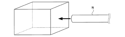
次に、コネクタ1の製造方法について説明する。コネクタ1を製造するには、まず、図7に示すように弾性部材を直方体に成型する。次にこの弾性部材にニードルNを刺し通すことで図1で説明した挿入口2および通路3を形成する。この様な工程を経てコネクタ1が製造される。
次に、コネクタ1の製造方法について説明する。コネクタ1を製造するには、まず、図7に示すように弾性部材を直方体に成型する。次にこの弾性部材にニードルNを刺し通すことで図1で説明した挿入口2および通路3を形成する。この様な工程を経てコネクタ1が製造される。
<コネクタの製造方法:量産する方法>
次に、コネクタ1を量産する方法について説明する。コネクタ1を量産するには、まず、図8に示す型を用意する。この型には、直方体形状の凹みが設けられている。この型には、互いに平行に配列された直線上の針金が凹みを通過するように設けられている。
次に、コネクタ1を量産する方法について説明する。コネクタ1を量産するには、まず、図8に示す型を用意する。この型には、直方体形状の凹みが設けられている。この型には、互いに平行に配列された直線上の針金が凹みを通過するように設けられている。
この凹みには、図9に示すように弾性体の原料となる主材と硬化剤の混合物が満たされる。主材は架橋率の低い液状のシリコーン樹脂、硬化剤には適切な架橋反応をのための架橋剤が含まれている。液状となっている弾性体原料は、針金の部分を除いて凹みの領域にくまなく行き渡る。こうして針金は、硬化前の弾性体原料の中に沈没した状態となる。
弾性体原料が反応により架橋・硬化したあと、図10に示すように、針金が型から引き抜かれる。硬化剤は、硬化により弾性体に変化しているので、針金は容易に引き抜かれることになる。この針金が取り除かれた部分は、弾性体内部に設けられた円筒状の空洞となり、将来的に通路3となる。
型から全ての針金が引き抜かれたあと、弾性体は型から抜かれて、図11の点線に示すような格子状に切断される。すると、図1で説明したコネクタ1が量産される。
以上のように、本発明の構成のコネクタ1は、通路3にチューブ4を挿入させるタイプのものである。この様なタイプのコネクタ1において、本発明の通路3の内径d3は、チューブ4の外径d4よりも小さくなるように設定されている。この様な構成では、チューブ4が通路3の内部に挿入できないのではないかとも思われる。しかし、本発明によればコネクタ1は弾性部材で構成される。したがって、チューブ4を通路3に挿入させようとすると、これに応じてチューブ4の先端が通路3を広げながら通路内部を進んでいく。結果として、チューブ4はコネクタ1に接続されることになる。
このとき、チューブ4の外径と通路3の内径との対応関係はさほど厳密でなくてもよい。太めのチューブ4がコネクタ1に挿入されたときには、通路3がより広く広げられる。結果としてチューブ4は、太めのものであろうと通路3に難なく進入できるのである。
これに比べて従来構成によれば、コネクタ1を高い精度で製造したり、多くの部品で構成したりしなければない。また、接続できるチューブ4の外径も厳密に決まっている。しかし、本発明の構成によれば、コネクタ1を簡単に製造できる上、高い精度が必要ともならないし、多くの部品が必要ともならない。さらに、接続できるチューブ4の外径は多様である。したがって、本発明によれば、使いやすいコネクタ1が提供できる。
また、本発明によれば、安価に製造できることからコネクタ1を簡単に使い捨てにすることができる。これは、コネクタ1を使用すると血液がコネクタ内部にこびりついてしまう事情を抱える採血の場面においては、コンタミネーションを防ぐことができる点で有利である。
また、本発明において、チューブ4が通路3に挿入されるときに、通路3は元の形状に戻ろうとしてチューブ4に圧力が加えるので、チューブ4とコネクタ1との間に十分に強い摩擦が生じることになる。したがって、本発明のコネクタ1によれば、チューブ4が簡単に外れることがない。
続いて、実施例2に係るコネクタ1について説明する。実施例2に係るコネクタ1の構成は実施例1のものと類似している。
実施例2に係るコネクタ1において実施例1と異なる点は、図12に示すように通路3の両端にテーパ部5が設けられていることにある。このテーパ部5は、通路3の中心3cから挿入口2に向かうに従って内径が次第に広くなるように形成されている。このテーパ部5は、通路3を構成した後に弾性部材を削り込むことで設けられる部分であり、この部分の内径は、必ずしも挿入されるチューブ4の外径より小さくする必要はない。この様に、実施例2においては挿入口2の内径と通路3の内径とが異なっている。
このような実施例2の構成は、チューブ4を先端から挿入させるテーパ部5と複数のテーパ部5とを連結する通路とが形成された弾性部材から構成されていると表現することもできる。
以上のように、実施例2に係るコネクタ1は、通路3の両端に通路3の中心から挿入口2に向かうに従って内径が次第に広がるテーパ部5が設けられている。このようにすれば、挿入口2は実施例1の場合と比べてより広くなっているので、チューブ4を挿入しやすいコネクタ1が提供できる。
本発明の構成は上述の構成に限られず、下記のように変形実施することができる。
(1)上述の構成によれば、通路3の内径は一定となっていたが、本発明はこの構成に限られない。すなわち、通路3の内径を図13のように部分的に変更するようにしてもよい。図13の例では、通路3を2つの挿入口2のそれぞれに近い側の2つの領域3a1,3a2と挿入口2から離れた領域3bとの3つの領域に分割し、領域3a1,3a2の内径を領域3bの内径よりも大きくしている。つまり、本変形例においては、挿入口2から遠い側に位置する通路3の内径が挿入口2に近い側に位置する通路3の内径よりも小さくなっている。とはいえ、領域3a1,3a2の内径は、挿入されるチューブ4の外径よりは小さく設定されている。
この様な変形例の構成によれば、領域3a,3cの内径が十分大きくなっているので、挿入口2も広くなりチューブ4の挿入がしやすい。また、領域3bの内径は十分小さくなっているので、コネクタ1を流れる液体のデットボリュームを極力少なくすることができる。
(2)上述の構成によれば、通路3は、直線状となっていたが、本発明の構成はこの構成に限られない。図14に示すように通路3をL形状としてもよい。
(3)上述の構成によれば、通路3は、直線状となっていたが、本発明の構成はこの構成に限られない。図15に示すように通路3を分岐させてもよい。分岐の方式としては例えば図15左側に示すようなπ形状や図15右側に示すようなT形状が考えられる。この様な場合、コネクタ1は、通路3が3つ以上の挿入口2を連絡し、流体を分岐するように構成されているということになる。
以上のように、本発明は研究分野やコネクタを用いる多様な分野に適している。
1 コネクタ(チューブ接続コネクタ)
2 挿入口
3 通路
4 チューブ
5 テーパ部
2 挿入口
3 通路
4 チューブ
5 テーパ部
Claims (6)
- チューブを先端から挿入させる挿入口と複数の前記挿入口を連結する通路とが形成された弾性部材から構成され、
前記通路の内径が挿入されるチューブの外径よりも小さくなっていることを特徴とするチューブ接続コネクタ。 - 請求項1に記載のチューブ接続コネクタにおいて、
前記弾性部材は、前記通路が前記挿入口より挿入された前記チューブに広げられるのに反発して、径を縮めようとする力を前記チューブに付与することを特徴とするチューブ接続コネクタ。 - 請求項1または請求項2に記載のチューブ接続コネクタにおいて、
前記通路の両端には前記通路の中心から前記挿入口に向かうに従って内径が次第に広がるテーパ部が設けられていることを特徴とするチューブ接続コネクタ。 - 請求項1ないし請求項3のいずれかに記載のチューブ接続コネクタにおいて、
前記挿入口から遠い側に位置する前記通路の内径が前記挿入口に近い側に位置する前記通路の内径よりも小さくなっていることを特徴とするチューブ接続コネクタ。 - 請求項1ないし請求項4のいずれかに記載のチューブ接続コネクタにおいて、
前記通路が2つの前記挿入口を連絡するように構成されていることを特徴とするチューブ接続コネクタ。 - 請求項1ないし請求項4のいずれかに記載のチューブ接続コネクタにおいて、
前記通路が3つ以上の前記挿入口を連絡し、流体を分岐するように構成されていることを特徴とするチューブ接続コネクタ。
Priority Applications (1)
| Application Number | Priority Date | Filing Date | Title |
|---|---|---|---|
| PCT/JP2012/005449 WO2014033775A1 (ja) | 2012-08-29 | 2012-08-29 | チューブ接続コネクタ |
Applications Claiming Priority (1)
| Application Number | Priority Date | Filing Date | Title |
|---|---|---|---|
| PCT/JP2012/005449 WO2014033775A1 (ja) | 2012-08-29 | 2012-08-29 | チューブ接続コネクタ |
Publications (1)
| Publication Number | Publication Date |
|---|---|
| WO2014033775A1 true WO2014033775A1 (ja) | 2014-03-06 |
Family
ID=50182627
Family Applications (1)
| Application Number | Title | Priority Date | Filing Date |
|---|---|---|---|
| PCT/JP2012/005449 Ceased WO2014033775A1 (ja) | 2012-08-29 | 2012-08-29 | チューブ接続コネクタ |
Country Status (1)
| Country | Link |
|---|---|
| WO (1) | WO2014033775A1 (ja) |
Cited By (3)
| Publication number | Priority date | Publication date | Assignee | Title |
|---|---|---|---|---|
| JP7390749B1 (ja) | 2022-05-27 | 2023-12-04 | ツカサ工業株式会社 | 管継手 |
| WO2024171077A1 (en) * | 2023-02-15 | 2024-08-22 | Sartorius Stedim FMT S.A.S. | Unions for joining fluid conduits |
| US12523322B2 (en) | 2023-02-15 | 2026-01-13 | Sartorius Stedim Fmt | Unions for joining fluid conduits |
Citations (5)
| Publication number | Priority date | Publication date | Assignee | Title |
|---|---|---|---|---|
| JPH0650481A (ja) * | 1992-03-16 | 1994-02-22 | Shinku Kiko Kk | 真空配管継手 |
| JPH06109184A (ja) * | 1991-12-13 | 1994-04-19 | Nippon Steel Corp | 薄肉パイプの締結方法 |
| JP2007146882A (ja) * | 2005-11-24 | 2007-06-14 | Dkk Toa Corp | 配管継手および配管の接続構造 |
| JP2008512235A (ja) * | 2004-09-09 | 2008-04-24 | アンスティテュート キュリー | マイクロチャネルまたは他のマイクロ容器中でパケットを操作するためのデバイス |
| JP2009072574A (ja) * | 2007-08-20 | 2009-04-09 | Atrion Medical Products Inc | 高圧医療ホース用結合ソケット |
-
2012
- 2012-08-29 WO PCT/JP2012/005449 patent/WO2014033775A1/ja not_active Ceased
Patent Citations (5)
| Publication number | Priority date | Publication date | Assignee | Title |
|---|---|---|---|---|
| JPH06109184A (ja) * | 1991-12-13 | 1994-04-19 | Nippon Steel Corp | 薄肉パイプの締結方法 |
| JPH0650481A (ja) * | 1992-03-16 | 1994-02-22 | Shinku Kiko Kk | 真空配管継手 |
| JP2008512235A (ja) * | 2004-09-09 | 2008-04-24 | アンスティテュート キュリー | マイクロチャネルまたは他のマイクロ容器中でパケットを操作するためのデバイス |
| JP2007146882A (ja) * | 2005-11-24 | 2007-06-14 | Dkk Toa Corp | 配管継手および配管の接続構造 |
| JP2009072574A (ja) * | 2007-08-20 | 2009-04-09 | Atrion Medical Products Inc | 高圧医療ホース用結合ソケット |
Cited By (5)
| Publication number | Priority date | Publication date | Assignee | Title |
|---|---|---|---|---|
| JP7390749B1 (ja) | 2022-05-27 | 2023-12-04 | ツカサ工業株式会社 | 管継手 |
| JP2023175059A (ja) * | 2022-05-27 | 2023-12-12 | ツカサ工業株式会社 | 管継手 |
| WO2024171077A1 (en) * | 2023-02-15 | 2024-08-22 | Sartorius Stedim FMT S.A.S. | Unions for joining fluid conduits |
| CN120641170A (zh) * | 2023-02-15 | 2025-09-12 | 赛多利斯斯泰帝生物科技 | 用于连结流体导管的接头 |
| US12523322B2 (en) | 2023-02-15 | 2026-01-13 | Sartorius Stedim Fmt | Unions for joining fluid conduits |
Similar Documents
| Publication | Publication Date | Title |
|---|---|---|
| KR101874156B1 (ko) | 연장 밀봉 슬리브 및 저류 방지 리테이너를 구비한 밀봉 커넥터 | |
| JP6840700B2 (ja) | シールされた電気コネクタアセンブリおよびワイヤシール | |
| EP3009162B1 (en) | Catheter and manufacturing method therefor | |
| JP6404619B2 (ja) | カテーテル製造用金型およびカテーテルの製造方法 | |
| CN206377352U (zh) | 密封组件 | |
| WO2014033775A1 (ja) | チューブ接続コネクタ | |
| CN101599593B (zh) | 线缆连接器 | |
| CN110603692A (zh) | 用于将插塞器装配在多芯的护套导线上的方法以及电的插塞器 | |
| CN104247156A (zh) | 插入式连接器的绝缘体 | |
| CA2916918C (en) | Pipe connecting sealing member having protrusion | |
| JP2018534066A5 (ja) | ||
| US20160233628A1 (en) | Connector and manufacturing method for connector | |
| US9863204B2 (en) | Downhole connector | |
| CN105762542B (zh) | 电连接器 | |
| US20150263446A1 (en) | Electrical Connector and Method for Producing an Electrical Connector | |
| ATE468629T1 (de) | Verfahren zur herstellung einer elektrisch leitenden verbindung | |
| TW201523050A (zh) | 可彎曲之光纖連接器的尾套 | |
| CN104698547A (zh) | 可弯曲的光纤连接器的尾套 | |
| US20160082244A1 (en) | Medical tube, method for manufacturing same, and tube connector | |
| CN113169537A (zh) | 电缆螺纹连接件 | |
| CN204477549U (zh) | 一种卡套 | |
| CN104352236B (zh) | 环抱电极 | |
| US20030025277A1 (en) | High Pressure seal | |
| KR101771231B1 (ko) | 의료용 튜브 커넥터 | |
| CN204243324U (zh) | 电线接线部的防水套 |
Legal Events
| Date | Code | Title | Description |
|---|---|---|---|
| 121 | Ep: the epo has been informed by wipo that ep was designated in this application |
Ref document number: 12883624 Country of ref document: EP Kind code of ref document: A1 |
|
| NENP | Non-entry into the national phase |
Ref country code: DE |
|
| 122 | Ep: pct application non-entry in european phase |
Ref document number: 12883624 Country of ref document: EP Kind code of ref document: A1 |
|
| NENP | Non-entry into the national phase |
Ref country code: JP |