WO2014033774A1 - Av装置 - Google Patents
Av装置 Download PDFInfo
- Publication number
- WO2014033774A1 WO2014033774A1 PCT/JP2012/005436 JP2012005436W WO2014033774A1 WO 2014033774 A1 WO2014033774 A1 WO 2014033774A1 JP 2012005436 W JP2012005436 W JP 2012005436W WO 2014033774 A1 WO2014033774 A1 WO 2014033774A1
- Authority
- WO
- WIPO (PCT)
- Prior art keywords
- unit
- speaker
- audio
- type
- slit
- Prior art date
- Legal status (The legal status is an assumption and is not a legal conclusion. Google has not performed a legal analysis and makes no representation as to the accuracy of the status listed.)
- Ceased
Links
Images





Classifications
-
- H—ELECTRICITY
- H04—ELECTRIC COMMUNICATION TECHNIQUE
- H04R—LOUDSPEAKERS, MICROPHONES, GRAMOPHONE PICK-UPS OR LIKE ACOUSTIC ELECTROMECHANICAL TRANSDUCERS; ELECTRIC HEARING AIDS; PUBLIC ADDRESS SYSTEMS
- H04R1/00—Details of transducers, loudspeakers or microphones
- H04R1/02—Casings; Cabinets ; Supports therefor; Mountings therein
-
- H—ELECTRICITY
- H04—ELECTRIC COMMUNICATION TECHNIQUE
- H04R—LOUDSPEAKERS, MICROPHONES, GRAMOPHONE PICK-UPS OR LIKE ACOUSTIC ELECTROMECHANICAL TRANSDUCERS; ELECTRIC HEARING AIDS; PUBLIC ADDRESS SYSTEMS
- H04R2205/00—Details of stereophonic arrangements covered by H04R5/00 but not provided for in any of its subgroups
- H04R2205/021—Aspects relating to docking-station type assemblies to obtain an acoustical effect, e.g. the type of connection to external loudspeakers or housings, frequency improvement
-
- H—ELECTRICITY
- H04—ELECTRIC COMMUNICATION TECHNIQUE
- H04R—LOUDSPEAKERS, MICROPHONES, GRAMOPHONE PICK-UPS OR LIKE ACOUSTIC ELECTROMECHANICAL TRANSDUCERS; ELECTRIC HEARING AIDS; PUBLIC ADDRESS SYSTEMS
- H04R2420/00—Details of connection covered by H04R, not provided for in its groups
- H04R2420/09—Applications of special connectors, e.g. USB, XLR, in loudspeakers, microphones or headphones
Definitions
- the present invention relates to an AV apparatus formed by joining a first device and a second device.
- a speaker input connector that is connected to a mobile terminal device and receives an audio signal (music signal) from the mobile terminal device, and the audio signal is separated into a high sound range, a mid sound range, and a low sound range and amplified.
- a speaker amplifier that distributes and a plurality of speakers that receive and output separated and amplified audio signals (see Patent Document 1).
- these parts are mounted on a flat housing.
- This invention makes it a subject to provide the AV apparatus which has high design property and high custom property.
- the AV apparatus removably joins a first device having a flat appearance and a second device linked to the first device and having a flat appearance at a joint portion.
- the first device has the same housing and is configured to be selectable from a plurality of types having different internal device configurations
- the second device has the same housing.
- the internal device can be selected from a plurality of different types.
- the first device is a control device having one or more internal devices including a control unit that reproduces the audio signal and / or video signal of the content from the source device, and the second device is the reproduced content.
- the output device has one or more internal devices including an output unit that outputs the audio signal and / or the video signal.
- the user can change the device configuration of the entire AV device by selecting devices (control device and output device) having different internal device configurations. Therefore, the AV device can be easily customized by the user.
- the devices having a flat appearance are joined to each other, it is possible to provide an AV device having a high design like a combination of two plates.
- the design (appearance) of the AV device will not change due to customization, and high design will be maintained. Can do.
- both devices have a flat appearance, the AV device can be easily carried / stored if the connection between both devices is released.
- the housing of the second device is configured to be selectable from a plurality of types having different appearance decorations.
- the “plurality of types having different external decorations” here is a concept including a housing to which various decorative covers are attached.
- the first device is formed in a rectangular shape
- the second device is formed in a rectangular shape
- the first device and the second device are in a joined state
- the output of the second device It is preferable that the first portion of the first device and the one side of the second device are formed in an intersecting appearance so that the portion is obliquely upward and the one side of the second device forms a leg portion.
- the joint part of the first device has a first slit part in which a part of the housing is removed in a cross-sectionally slit-like manner at a width corresponding to the thickness of the second device at the intersection
- the joint portion of the device has a second slit portion in which a part of the casing is removed in a cross-sectional direction in a cross-sectional manner at a crossing portion in a width corresponding to the thickness of the first device. It is preferable that the device is joined by fitting the first slit portion and the second slit portion to each other in the transverse direction.
- the two slit portions can firmly join the devices while maintaining high design.
- the joining portion of the first device further includes a first connector facing the joining direction on the end surface of the first slit portion, and the joining portion of the second device is joined to the end surface of the second slit portion in the joining direction.
- the first connector and the second connector are preferably connected by fitting the first slit portion and the second slit portion.
- one or more internal devices including the control unit charge a device connection unit to which the source device is connected, a wireless communication unit that performs wireless communication with the source device, a radio reception unit, and the source device.
- the one or more internal devices including at least one charging unit and including the output unit include at least one of one or more speaker units and an effect lighting unit.
- the AV device can be customized to various device configurations.
- the speaker unit is disposed on the front side and the effect lighting unit is disposed on the back side.
- the speaker unit and the effect lighting unit (especially the indirect lighting unit using the wall on the back of the AV device) can be suitably arranged.
- the joined first device and the second device are formed in an orthogonal appearance, and the first device can be joined to the second device in an inverted state. It is preferable.
- each device can be joined in a state where the front and back sides are reversed, so that different internal devices and other external decorations are provided on the front side and the back side of each device so that they can be used reversibly. Can do. Therefore, customizability can be further improved.
- the first device is formed in a rectangular shape
- the second device is formed in a larger rectangle than the first device
- the first device is a surface on the output unit side of the second device. It is preferable that they are joined so as to overlap each other.
- the one or more internal devices including the control unit include a control unit, a device connection unit to which the source device is connected, a wireless communication unit that performs wireless communication with the source device, a charging unit that charges the source device, and
- the one or more internal devices including at least one of the display units and including the output unit preferably include one or more speaker units.
- the AV device can be customized to various device configurations.
- the first device is formed in a rectangle
- the second device is formed in a rectangle
- the first device has a seating surface on the back side
- the second device has an output unit. It is preferable to be joined to the rear surface of the first device so as to be obliquely upward.
- the one or more internal devices including the control unit include at least one of a device connection unit to which the source device is connected, a charging unit for charging the source device, and a speaker unit in addition to the control unit, and an output
- the one or more internal devices including the unit preferably include a display unit.
- the AV device can be customized to various device configurations.
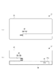
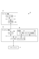
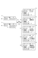
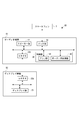
- the perspective view (a) and sectional view (b) which showed the audio equipment concerning a 1st embodiment. It is the top view which showed the speaker apparatus (a) and amplifier apparatus (b) of an audio apparatus. It is the perspective view which showed the joining structure of the speaker apparatus and the amplifier apparatus. It is the block diagram which showed the internal structure of the audio apparatus. It is the block diagram which showed the customization system of the audio apparatus. It is the perspective view (a) and sectional drawing (b) which showed the audio apparatus of 2nd Embodiment. It is the perspective view which showed the joining structure of the speaker apparatus and display apparatus in 2nd Embodiment. It is the block diagram which showed the internal structure of the audio apparatus of 2nd Embodiment.
- This audio device is an audio output device for a smartphone (so-called dock speaker) that wears a smartphone (source device) and outputs an audio signal from the smartphone.
- the audio device 1 includes a speaker device (output device: second device) 11 having a rectangular flat plate appearance and an amplifier device (a second device) 11 having a rectangular flat plate appearance and a smartphone S (see FIG. 1).
- the audio device 1 is formed by joining the speaker device 11 and the amplifier device 12 so as to be orthogonal to each other when viewed from the side.
- the external appearance of the speaker device 11 is formed by a rectangular flat plate-like casing 21, and the speaker device 11 is arranged obliquely so that the surface side is obliquely upward. That is, the speaker device 11 is disposed so that the front side faces the user. Further, a speaker unit (output unit) 22 composed of a planar speaker is disposed on the surface side of the speaker device 11, and the speaker unit 22 faces obliquely upward (user side). On the other hand, on the back side of the speaker device 11, an illumination unit (effect illumination unit) 23 composed of an OLED (array of organic EL diodes) is disposed.
- OLED array of organic EL diodes
- the speaker device 11 is provided with a joint portion 25 for joining the amplifier device 12 at the intersection with the amplifier device 12.
- the joint portion 25 of the speaker device 11 includes a slit portion (second slit portion) 25a formed at the intersecting portion of the housing 21, and a female side disposed on the end surface of the slit portion 25a so as to face the joining direction. And a connector (second connector) 25b.
- the slit portion 25a is formed by removing a part of the housing 21 in a slit shape in the transverse direction with a width corresponding to the thickness of the amplifier device 12 at the intersection.
- the amplifier device 12 has an external appearance formed by a rectangular flat plate-shaped casing 31 and is disposed obliquely so as to be orthogonal to the speaker device 11.
- a dock portion (device connection portion) 32 that is placed in front of the speaker device 11 and on which the smartphone S is mounted (removably connected) is disposed.
- the mounted smartphone S is arranged following the speaker device 11 by the dock unit 32.
- the smartphone S is disposed obliquely upward (facing the user).
- a concave portion 31 a into which the lower end portion of the smartphone S enters is formed on the surface of the housing 31 around the dock portion 32.
- an operation unit 33 constituted by a touch sensor is disposed, and a power button 33a and the like are disposed.
- the area in front of the speaker device 11 on the surface of the amplifier device 12 is an accessory storage portion 34 for placing various portable items such as keys and ornaments. Since the accessory storage unit 34 is disposed around the dock unit 32, various portable items can be stored together with the smartphone S attached to the dock unit 32. Since the surface of the casing 31 is inclined, the accessory storage part 34 is inclined so as to become lower toward the speaker device 11. As a result, the portable article placed is configured not to fall.
- the amplifier device 12 is provided with a joint portion 35 for joining the speaker device 11 at the intersection with the speaker device 11.
- the joint portion 35 of the amplifier device 12 includes a slit portion (first slit portion) 35a formed at the intersecting portion of the housing 31 and a male side disposed on the end surface of the slit portion 35a so as to face the joining direction. And a connector (first connector) 35b.
- the slit portion 35a is formed by removing a part of the housing 31 in a slit shape in the transverse direction with a width corresponding to the thickness of the speaker device 11 at the intersection.
- the speaker device 11 and the amplifier device 12 are detachably joined by fitting both the slit portions 25a and 35a to each other in the transverse direction. Then, the speaker device 11 and the amplifier device 12 are joined in an orthogonal appearance (cross section plus shape), and one side (lower end portion) of the speaker device 11 and one side (rear end portion) of the amplifier device 12 are combined. ) Constitutes the leg. That is, the amplifier device 12 also functions as a stand that supports the speaker device 11 obliquely upward. Further, by fitting both the slit portions 25a and 35a, the both connectors 25b and 35b are connected, and the speaker device 11 and the amplifier device 12 are electrically connected (linked).
- the speaker device 11 includes the speaker unit 22, the illumination unit 23, and the connector 25b as internal devices.
- the speaker unit 22 is composed of a non-directional flat speaker (HVT system), and outputs (sounds) the audio signal transferred from the amplifier device 12 in a non-directional manner.
- the illumination part 23 is comprised by OLED, and performs indirect illumination using the wall of the audio apparatus 1 back surface. For example, the illumination unit 23 emits light in various colors in conjunction with an audio signal.
- the amplifier device 12 includes the dock unit 32, the operation unit 33, the connector 35b, and the control unit 36 as internal devices.
- the control unit 36 includes an amplifier unit 41 that amplifies an audio signal and an audio control unit 42.
- the audio control unit 42 reproduces (controls) the audio signal of the content from the smartphone S. Specifically, a control signal is transmitted to the smartphone S to control the smartphone S, and an audio signal received from the smartphone S is transferred to the speaker device 11 via the amplifier unit 41.
- the audio apparatus 1 receives the audio signal (content) sequentially transferred from the smartphone S by the amplifier device 12 via the dock unit 32. Thereafter, the amplifier device 12 amplifies the received audio signal by the amplifier unit 41, and sequentially transfers it to the speaker device 11 via both connectors 25b and 35b. Then, the speaker device 11 sequentially outputs the transferred audio signal through the speaker unit 22.
- the speaker device 11 and the amplifier device 12 are configured to be selectable from a plurality of types having different internal configurations.
- the speaker device 11 is configured to be selectable from a plurality of types having the same (common) casing 21 and having different internal device configurations.
- the plural types of speaker devices 11 have the same (common) joint portion 25.
- the above-described speaker device 11 will be described as an A-type speaker device 11a, and the speaker device 11 that can be replaced with this will be described as a B-type speaker device 11b, a C-type speaker device 11c, and a D-type speaker device 11d.
- the B-type speaker device 11b has a configuration in which one speaker unit 22 is added to the A-type speaker device 11a. That is, the B-type speaker device 11b includes two speaker units 22, an illumination unit 23, and a connector 25b as internal devices. In the B-type speaker device 11b, two speaker portions 22 are arranged on the left and right sides of the surface side and used as LR speakers.
- the C-type speaker device 11c has a configuration in which the illumination unit 23 is omitted from the A-type speaker device 11a. That is, the C-type speaker device 11c includes one speaker unit 22 and a connector 25b as internal devices.
- the D-type speaker device 11d has a configuration in which the illumination unit 23 is omitted and one speaker unit 22 is added to the A-type speaker device 11a. That is, the D-type speaker device 11d includes two speaker units 22 and a connector 25b as internal devices. In the D-type speaker device 11d, as in the B-type speaker device 11b, two speaker portions 22 are arranged on the left and right sides of the surface side and used as LR speakers.
- the amplifier device 12 has the same (common) casing 31 and can be selected from a plurality of types having different internal device configurations.
- the plural types of amplifier devices 12 have the same (common) joint portion 35.
- the above-described amplifier device 12 is an A-type amplifier device 12a
- amplifier devices 12 that can be replaced with the A-type amplifier device 12a are a B-type amplifier device 12b, a C-type amplifier device 12c, a D-type amplifier device 12d, and an E-type amplifier device 12e. Will be described.
- the B-type amplifier device 12b has a configuration in which a wireless communication unit 51 is added to the A-type amplifier device 12a instead of the dock unit 32. That is, the B-type amplifier device 12b includes an operation unit 33, a connector 35b, a control unit 36, and a wireless communication unit 51 as internal devices.
- the wireless communication unit 51 is configured by Airplay (registered trademark), and performs communication with the smartphone S placed on the accessory storage unit 34 by wireless communication.
- the C-type amplifier device 12c has a configuration in which a wireless communication unit 51 is added to the A-type amplifier device 12a. That is, the C-type amplifier device 12c includes a dock unit 32, an operation unit 33, a connector 35b, a control unit 36, and a wireless communication unit 51 as internal devices.
- the D-type amplifier device 12d has a configuration in which a radio receiver 52 is added to the A-type amplifier device 12a. That is, the D-type amplifier device 12d includes a dock unit 32, an operation unit 33, a connector 35b, a control unit 36, and a radio reception unit 52 as internal devices.
- the radio receiver 52 receives and converts radio waves and outputs radio sound signals.
- the E-type amplifier device 12e has a configuration in which a wireless communication unit 51 and a non-contact charging unit (charging unit) 53 are added to the A-type amplifier device 12a instead of the dock unit 32. That is, the E-type amplifier device 12e includes an operation unit 33, a connector 35b, a control unit 36, a wireless communication unit 51, and a non-contact charging unit 53 as internal devices.
- the non-contact charging unit 53 transmits power to the smartphone S placed on the accessory storage unit 34 to charge the smartphone S.
- the speaker device 11 can be selected from the A-type speaker device 11a, the B-type speaker device 11b, the C-type speaker device 11c, and the D-type speaker device 11d
- the amplifier device 12 can be selected from the A-type amplifier device 12a and the B-type speaker device 11b.
- the type amplifier device 12b, the C type amplifier device 12c, the D type amplifier device 12d, and the E type amplifier device 12e can be selected.
- the user can change the overall device configuration of the audio device 1 by selecting the speaker device 11 and the amplifier device 12 having different internal configurations, and can freely customize the audio device 1.
- the configuration of the first embodiment it is possible to obtain high designability while maintaining functionality by being formed into an external shape in which the flat-shaped external devices 11 and 12 are crossed.
- the speaker unit 22 and the illumination unit 23 can be suitably disposed by disposing the speaker unit 22 on the front side and the illumination unit 23 on the back side.
- the devices 11 and 12 can be firmly joined with each other while maintaining high design by the both slit portions 25a and 35a. .
- both the connectors 25b and 35b are connected by fitting both the slit portions 25a and 35a, the devices 11 and 12 are linked to each other by joining the devices 11 and 12 to each other. Therefore, since no special work (connection cable connection, etc.) or special processing (link connection by wireless communication) is required to link the devices, the user can easily set up the audio device 1. it can.
- the amplifier device 12 may be configured to be able to be joined to the speaker device 11 in an inverted state. According to such a configuration, since the devices 11 and 12 can be joined in a state where the front and back are reversed, the devices 11 and 12 can be used reversibly. Therefore, customizability can be further improved.
- the amplifier device 12 may be provided with other internal devices on the front surface side and the back surface side. For example, another type of dock unit 32 may be provided on the front side and the back side of the amplifier device 12.
- casing 21 and 31 may be sufficient.
- a rail-like convex portion extending in the joining direction is disposed on the inner side surface of the slit portion 25a in the amplifier device 12, and a shape complementary to the convex portion is formed in a corresponding portion of the front and back surfaces of the speaker device 11. It is set as the structure which arrange
- the audio device 60 of the present embodiment is used by being hung on a wall.
- the audio device 60 of the present embodiment has a speaker device (second device: output device) 61 having a rectangular flat plate appearance and a rectangular flat plate appearance smaller than the speaker device 61.
- the audio device 60 is configured by joining the speaker device 61 and the display device 62 so as to overlap each other.
- the external appearance of the speaker device 61 is formed by a rectangular flat plate-like casing 71.
- a speaker unit (output unit) 22 is disposed on the front side of the speaker device 61, and a wall hanging unit (not shown) for hanging the audio device 60 is disposed on the back side.
- a joint recess 72 formed in the housing 71 and a connector 25 b provided in the center of the joint recess 72 are disposed at the center of the surface of the speaker device 61.
- the external appearance of the display device 62 is formed by a rectangular flat plate-like casing 73, and is arranged on the speaker device 61.
- a display unit 75 constituted by an LCD (liquid crystal display) is disposed on the surface side of the display device 62.
- a dock unit 32 for connecting the smartphone S is disposed at the upper end of the display device 62.
- a connector 35 b is disposed on the back side of the display device 62.
- the speaker device 61 and the display device 62 are detachably joined by fitting the latter half of the display device 62 into the joining recess 72. Accordingly, the display device 62 is joined so as to overlap the surface of the speaker device 61 on the speaker unit 22 side. Further, by fitting the latter half of the display device 62 into the joint recess 72, both the connectors 25b and 35b are connected accordingly, and the speaker device 11 and the amplifier device 12 are electrically connected (linked).
- the junction part of the speaker apparatus 61 is comprised by the junction recessed part 72 and the connector 25b
- the junction part of the display apparatus 62 is comprised by the latter half part of the housing
- the speaker device 61 includes a speaker unit 22 and a connector 25b as internal devices.
- the display device 62 includes a dock unit 32, a connector 35b, a control unit 36, and a display unit 75 as internal devices.
- the display unit 75 is composed of an LCD and displays various images. Specifically, a clock, a jacket image of the music to be reproduced, and eventually an application screen of an application installed in the smartphone S are displayed.
- the audio signal (content) sequentially transferred from the smartphone S is received by the display device 62 via the dock unit 32. Thereafter, the display device 62 amplifies the received audio signal by the amplifier unit 41 and sequentially transfers it to the speaker device 61 via both connectors 25b and 35b. Then, the speaker device 61 sequentially outputs the transferred audio signal by the speaker unit 22.
- the video signal transferred from the smartphone S is received by the display device 62 via the dock unit 32.
- the display device 62 displays the received video signal on the display unit 75.
- the customization system in the audio apparatus 60 of 2nd Embodiment is demonstrated.
- the speaker device 61 and the display device 62 can be selected from a plurality of types having different internal configurations.
- the speaker device 61 is configured to be selectable from a plurality of types having the same (common) casing 71 and having different internal device configurations.
- the plural types of speaker devices 61 have the same (common) joint.
- the above-described speaker device 61 will be described as an A-type speaker device 61a, and the speaker device 61 that can be replaced with this will be described as a B-type speaker device 61b.
- the B-type speaker device 61b has a configuration in which one speaker unit 22 is added to the A-type speaker device 61a. That is, the B-type speaker device 61b includes two speaker units 22 and a connector 25b as internal devices. In the B-type speaker device 61b, two speaker portions 22 are arranged on the left and right sides of the surface side, and are used as LR speakers.
- the display device 62 has the same (common) casing 73 and is configured to be selectable from a plurality of types having different internal device configurations.
- the plurality of types of display devices 62 have the same (common) joint.
- the display device 62 described above is an A-type display device 62a
- display devices 62 that can be replaced with the A-type display device 62a are B-type display device 62b, C-type display device 62c, D-type display device 62d, and E-type display device 62e. Will be described.
- the B-type display device 62b has a configuration in which a wireless communication unit 51 is added to the A-type display device 62a in place of the dock unit 32. That is, the B-type display device 62b includes a connector 35b, a control unit 36, a wireless communication unit 51, and a display unit 75 as internal devices.
- the wireless communication unit 51 performs communication with the smartphone S placed on the upper end portion of the housing 73 by wireless communication.
- the C-type display device 62c has a configuration in which a wireless communication unit 51 is added to the A-type display device 62a. That is, the C-type display device 62c includes a dock unit 32, a connector 35b, a control unit 36, a wireless communication unit 51, and a display unit 75 as internal devices.
- the D-type display device 62d has a configuration in which a radio receiver 52 is added to the A-type display device 62a. That is, the D-type display device 62d includes a dock unit 32, a connector 35b, a control unit 36, a radio reception unit 52, and a display unit 75 as internal devices.
- the radio receiver 52 receives and converts radio waves and outputs radio sound signals.
- the E-type display device 62e has a configuration in which a wireless communication unit 51 and a non-contact charging unit 53 are added to the A-type display device 62a in place of the dock unit 32. That is, the E-type display device 62e includes a connector 35b, a control unit 36, a wireless communication unit 51, a non-contact charging unit 53, and a display unit 75 as internal devices.
- the non-contact charging unit 53 transmits power to the smartphone S placed on the upper end portion of the housing 73.
- the configuration of the second embodiment it is possible to obtain high designability while maintaining functionality by joining the flat-appearance devices 61 and 62 to form a stepped flat plate.
- the audio device 80 of the present embodiment has a rectangular flat plate appearance, an audio device (first device: control device) 81 on which the smartphone S is mounted, and a rectangular flat plate appearance.
- Display device (second device: output device) 82 which are detachably joined to each other at a joint portion.
- the audio device 80 is configured by joining an audio device 81 and a display device 82 so as to have a substantially inverted “T” shape.
- the external appearance of the audio device 81 is formed by a rectangular flat plate-shaped casing 91.
- the speaker unit 22 is disposed on the front surface side of the audio device 81, while the back surface side of the audio device 81 is a seating surface.
- a groove portion 92 extending in the transverse direction is disposed at a rear position thereof.
- a dock portion 32 for connecting the smartphone S and a connector 25b are disposed.
- the smartphone S and the display device 82 are held at a predetermined angle (diagonally upward) by the groove portion 92.
- illustration of the dock part 32 is abbreviate
- the appearance of the display device 82 is formed by a rectangular flat plate-like casing 93, and the display device 82 is disposed obliquely so that the surface side is obliquely upward. That is, the display device 82 is disposed so that the front side faces the user. Further, a display unit (output unit) 75 is disposed on the surface side of the display device 82, and the display unit 75 is configured to face obliquely upward (user side). Further, a connector 35 b is disposed on the lower end surface of the display device 82.
- the display device 82 is joined to the rear surface of the audio device 81 by inserting the lower end portion of the display device 82 into the groove portion 92 and connecting both the connectors 25b and 35b. Further, the audio device 81 and the display device 82 are electrically connected (linked) by connecting both the connectors 25b and 35b. Note that the joint portion of the audio device 81 is constituted by the groove portion 92 and the connector 25b, and the joint portion of the display device 82 is constituted by the lower end portion of the housing 93 and the connector 35b.
- the audio device 81 includes a speaker unit 22, a connector 25b, a dock unit 32, and a control unit 36 as internal devices.
- the display device 82 includes a connector 35b and a display unit 75 as internal devices.
- Audio device 80 receives audio signals sequentially transferred from smartphone S by audio device 81 via dock unit 32. Thereafter, the audio device 81 amplifies the received audio signal by the amplifier unit 41 and sequentially outputs the audio by the speaker unit 22. On the other hand, a video signal (content) transferred from the smartphone S is received by the audio device 81 via the dock unit 32. Thereafter, the received video signal is transferred to the display device 82 via both connectors 25b and 35b. The display device 82 displays the transferred video signal on the display unit 75.
- the customization system in the audio apparatus 80 of 3rd Embodiment is demonstrated.
- the audio device 81 and the display device 82 can be selected from a plurality of types having different internal configurations.
- the audio device 81 is configured to be selectable from a plurality of types having the same (common) casing 91 and having different internal device configurations. Further, the plurality of types of audio devices 81 have the same (common) joint.
- the audio device 81 described above is an A-type audio device 81a
- the audio devices 81 that can be replaced with the A-type audio device 81a are a B-type audio device 81b, a C-type audio device 81c, a D-type audio device 81d, and an E-type audio device 81e.
- the F-type audio equipment 81f will be described.
- the B-type audio device 81b has a configuration in which one speaker unit 22 is added to the A-type audio device 81a. That is, the B-type audio device 81b includes two speaker units 22, a connector 25b, a dock unit 32, and a control unit 36 as internal devices. In the B-type audio device 81b, the two speaker portions 22 are arranged on the left and right sides of the surface side, and are used as LR speakers.
- the C-type audio device 81c has a configuration in which a wireless communication unit 51 is added to the A-type audio device 81a instead of the dock unit 32. That is, the C-type audio device 81c includes a speaker unit 22, a connector 25b, a control unit 36, and a wireless communication unit 51 as internal devices.
- the wireless communication unit 51 performs communication with the smartphone S placed in the groove portion 92 by wireless communication.
- the D-type audio device 81d has a configuration in which a wireless communication unit 51 is added to the A-type audio device 81a. That is, the D-type audio device 81d includes a speaker unit 22, a connector 25b, a dock unit 32, a control unit 36, and a wireless communication unit 51 as internal devices.
- the E-type audio device 81e has a configuration in which a radio receiver 52 is added to the A-type audio device 81a. That is, the E-type audio device 81e includes a speaker unit 22, a connector 25b, a dock unit 32, a control unit 36, and a radio reception unit 52 as internal devices.
- the F-type audio device 81f has a configuration in which a wireless communication unit 51 and a non-contact charging unit 53 are added to the A-type audio device 81a instead of the dock unit 32. That is, the F-type audio device 81f includes the speaker unit 22, the connector 25b, the control unit 36, the wireless communication unit 51, and the non-contact charging unit 53 as internal devices.
- the non-contact charging unit 53 transmits power to the smartphone S placed in the groove part 92.
- the display device 82 has the same (common) casing 93 and is configured to be selectable from a plurality of types having different internal device configurations. Moreover, the multiple types of display devices 82 have the same (common) joint.
- the above-described display device 82 will be described as an A-type display device 82a, and the display device 82 that can be replaced with this will be described as a B-type display device 82b.
- the B-type display device 82b has a configuration in which a touch sensor unit 94 is added to the A-type display device 82a. That is, the B-type display device 82b includes a connector 35b, a display unit 75, and a touch sensor unit 94. The touch sensor unit 94 is disposed so as to overlap the display unit 75, and the display unit 75 and the touch sensor unit 94 constitute a touch panel.
- the configuration of the third embodiment it is possible to obtain high designability while maintaining functionality by joining the devices having flat appearances to form a substantially inverted “T” shape.
- the user can change the overall device configuration of the audio devices 1, 60, and 80 by selecting devices having different internal device configurations. Therefore, the audio devices 1, 60, and 80 can be easily customized by the user.
- the devices having a flat appearance are joined to each other, it is possible to provide audio devices 1, 60, and 80 that have a high design like a combination of two plates.
- the design (appearance) of the audio devices 1, 60, and 80 is not changed by customization, and high design can be maintained. it can.
- both devices have a flat appearance, the audio devices 1, 60, and 80 can be easily carried / stored if the connection between both devices is released.
- the amplifier device 12, the display device 62, and the housings 31, 72, 91 of the audio device 81, which are control devices can be selected from a plurality of types having different appearance decorations. good.
- it may be configured such that the casings 31, 72, 91 of the devices 12, 62, 81 can be selected from those painted in different colors / patterns.
- casing 31,72,91 from which an external decoration differs may be sufficient by attaching the various decoration covers (jersey) from which an ornament is different to the housing
- the connectors 25b and 35b are connected to each other to electrically connect both devices.
- both devices have wireless communication units instead of the connectors 25b and 35b.
- the configuration may be such that the devices are linked by wireless communication.
- the present invention is applied to the audio devices 1, 60, and 80 that are equipped with the smartphone S.
- the portable device is attached, for example, a portable audio player, a tablet PC, and a cellular phone.
- the present invention may be applied to an audio device to which a device is mounted.
- a configuration in which a source device (such as a portable terminal or a CD player) is connected via a cable, or a configuration in which the source device is built in the audio devices 1, 60, and 80 can be considered.
- Audio device 11: Speaker device, 12: Amplifier device, 21: Housing, 22: Speaker unit, 23: Lighting unit, 25: Joining unit, 25a: Connector, 25b: Slit unit, 31: Housing, 32 : Dock part 35: Joint part 35a: Connector 35b: Slit part 36: Control part 51: Wireless communication part 52: Radio reception part 53: Non-contact charging part 60: Audio device 61: Speaker Device 62: display device 71: housing 73: housing 75: display unit 80: audio device 81: audio device 82: display device 91: housing 93: housing S: smartphone
Landscapes
- Physics & Mathematics (AREA)
- Engineering & Computer Science (AREA)
- Acoustics & Sound (AREA)
- Signal Processing (AREA)
- Circuit For Audible Band Transducer (AREA)
Description
本発明は、第1の機器と第2の機器とを接合して成るAV装置に関するものである。
従来、AV装置として、携帯端末装置に接続され、携帯端末装置からの音声信号(音楽信号)を受けるスピーカー入力コネクタと、音声信号を、高音域、中音域、低音域に分離し、増幅して分配するスピーカーアンプと、分離・増幅された音声信号を受け、これを出力する複数のスピーカーと、を備えたものが知られている(特許文献1参照)。このAV装置では、これら各部を、平板状の筐体に搭載している。
しかしながら、従来のAV装置では、各部が単一の筐体に搭載されているので、カスタム性が低くまたデザイン性(意匠性)が低いという問題があった。すなわち、ユーザーが、AV装置の装置構成をカスタマイズしようとした場合、筐体自体を改造しなければならない。そのため、カスタマイズが極めて煩雑であった。また、筐体自体を改造した結果、AV装置の意匠が変わってしまい、デザイン性が低下してしまう場合もある。
これに対し、カスタム性を向上すべく、筐体に対して、スピーカーや演出照明部等の装置を外側から着脱可能とする構成も考えられるが、これでは、デザイン性が著しく低下してしまうという問題が生じた。
これに対し、カスタム性を向上すべく、筐体に対して、スピーカーや演出照明部等の装置を外側から着脱可能とする構成も考えられるが、これでは、デザイン性が著しく低下してしまうという問題が生じた。
本発明は、高いデザイン性と高いカスタム性とを有するAV装置を提供することを課題としている。
本発明のAV装置は、平板状の外観を有する第1の機器と、第1の機器にリンクすると共に平板状の外観を有する第2の機器と、を相互の接合部において着脱自在に接合して成るAV装置であって、第1の機器は、同一の筐体を有し内部装置の構成が異なる複数種のものから選択可能に構成され、第2の機器は、同一の筐体を有し内部装置の構成が異なる複数種のものから選択可能に構成されていることを特徴とする。
この場合、第1の機器は、ソース機器からのコンテンツの音声信号および/または映像信号を再生する制御部を含む1以上の内部装置を有するコントロール機器であり、第2の機器は、再生したコンテンツの音声信号および/または映像信号を出力する出力部を含む1以上の内部装置を有する出力機器であることが好ましい。
これらの構成によれば、ユーザーは、内部装置の構成が異なる機器(コントロール機器および出力機器)を選択することで、AV装置全体の装置構成を変えることができる。そのため、ユーザーによって容易にAV装置をカスタマイズすることができる。また、平板状の外観を有する機器同士を接合して形成されているので、2枚の板を組み合わせたようなデザイン性の高いAV装置を提供することができる。さらに、複数種の機器で、同一の筐体(共通の筐体)を有しているので、カスタマイズによって、AV装置の意匠(外観)が変わってしまうことがなく、高いデザイン性を維持することができる。またさらに、両機器が平板状外観を有するため、両機器の接合を解除すれば、AV装置の携帯/収納がしやすい。
この場合、第2の機器の筐体は、外観装飾の異なる複数種のものから選択可能に構成されていることが好ましい。
この構成によれば、第2の機器の外観装飾を容易にカスタマイズすることができる。ここにいう「外観装飾の異なる複数種のもの」は、各種装飾カバーを取り付けた筐体を含む概念である。
上記のAV装置において、第1の機器は、矩形に形成され、第2の機器は、矩形に形成され、第1の機器と第2の機器とは、接合状態で、第2の機器の出力部を斜め上向きとし、且つ第1の機器の1の辺と第2の機器の1の辺とが脚部を構成するように、交差した外観形状に形成されていることが好ましい。
この構成によれば、平板状外観の機器同士をクロスした外観形状に形成されていることで、機能性を維持しつつ、高いデザイン性を得ることができる。
この場合、第1の機器の接合部は、交差部分において筐体の一部を第2の機器の厚みに相当する幅で横断方向にスリット状に除去した第1スリット部を有し、第2の機器の接合部は、交差部分において筐体の一部を第1の機器の厚みに相当する幅で横断方向にスリット状に除去した第2スリット部を有し、第1の機器と第2の機器とは、第1スリット部および第2スリット部を横断方向において相互に嵌め合わせることで接合されていることが好ましい。
この構成によれば、両スリット部により、高いデザイン性を維持しつつ、機器同士を強固に接合させることができる。
この場合、第1の機器の接合部は、第1スリット部の端面に接合方向に向く第1コネクタを更に有し、第2の機器の接合部は、第2スリット部の端面に接合方向に向く第2コネクタを更に有し、第1コネクタと第2コネクタとは、第1スリット部および第2スリット部を嵌め合わせることで接続されることが好ましい。
この構成によれば、両スリット部を嵌め合わせることで、両コネクタが接続されるので、機器同士を接合することで、機器同士が相互にリンクする。よって、機器同士をリンクするのに特段の作業(接続ケーブルの接続等)や特段の処理(無線通信によるリンク接続)を必要としないため、ユーザーが、AV装置のセットアップを容易に行うことができる。
また、制御部を含む1以上の内部装置は、制御部に加え、ソース機器が接続される機器接続部、ソース機器との無線通信を行う無線通信部、ラジオ受信部およびソース機器に充電を行うための充電部の少なくとも1つを含み、出力部を含む1以上の内部装置は、1以上のスピーカー部および演出照明部の少なくとも1つを含むことが好ましい。
この構成によれば、AV装置を、多種多様な装置構成にカスタマイズすることができる。
さらに、第2の機器において、スピーカー部は表側に、演出照明部は裏側にそれぞれ配設されていることが好ましい。
この構成によれば、スピーカー部および演出照明部(特にAV装置背面の壁を利用した間接照明部)を好適に配設することができる。
またさらに、接合状態の第1の機器と第2の機器とは、直交した外観形状に形成され、第2の機器に対し第1の機器は、表裏反転した状態で接合可能に構成されていることが好ましい。
この構成によれば、各機器を、表裏反転した状態で接合することができるため、各機器の表面側と裏面側とに別の内部装置や別の外観装飾を設けて、リバーシブルで利用することができる。よって、カスタム性をより向上することができる。
上記のAV装置において、第1の機器は、矩形に形成され、第2の機器は、第1の機器より大きい矩形に形成され、第1の機器は、第2の機器の出力部側の面に重ねるように接合されていることが好ましい。
この構成によれば、平板状外観の機器同士を接合して段付き平板状に形成することで、機能性を維持しつつ、高いデザイン性を得ることができる。
この場合、制御部を含む1以上の内部装置は、制御部、ソース機器が接続される機器接続部、ソース機器との無線通信を行う無線通信部、ソース機器に充電を行うための充電部およびディスプレイ部の少なくとも1つを含み、出力部を含む1以上の内部装置は、1以上のスピーカー部を含むことが好ましい。
この構成によれば、AV装置を、多種多様な装置構成にカスタマイズすることができる。
上記のAV装置において、第1の機器は、矩形に形成され、第2の機器は、矩形に形成され、第1の機器は、裏面側を着座面とし、第2の機器は、出力部が斜め上向きとなるように、第1の機器の後部表面に接合されていることが好ましい。
この構成によれば、平板状外観の機器同士を接合して略逆「T」字状に形成することで、機能性を維持しつつ、高いデザイン性を得ることができる。
この場合、制御部を含む1以上の内部装置は、制御部に加え、ソース機器が接続される機器接続部、ソース機器に充電を行うための充電部およびスピーカー部の少なくとも1つを含み、出力部を含む1以上の内部装置は、ディスプレイ部を含むことが好ましい。
この構成によれば、AV装置を、多種多様な装置構成にカスタマイズすることができる。
以下、添付の図面を参照して、本発明の一実施形態に係るAV装置について説明する。実施形態では、本発明のAV装置を適用したオーディオ装置およびそのカスタマイズシステムを例示する。このオーディオ装置は、スマートフォン(ソース機器)を装着し、スマートフォンからの音声信号を音声出力するスマートフォン用の音声出力装置(いわゆるドックスピーカー)である。
図1に示すように、オーディオ装置1は、矩形平板状の外観を有するスピーカー機器(出力機器:第2の機器)11と、矩形平板状の外観を有すると共に、スマートフォンSを装着するアンプ機器(コントロール機器:第1の機器)12と、を備え、これらを相互の接合部25、35において着脱自在に接合して構成されている。また、オーディオ装置1は、スピーカー機器11およびアンプ機器12を側面視で直交するように接合して成る。
図1および図2に示すように、スピーカー機器11は、矩形平板状の筐体21により外観が形成されており、表面側が斜め上向きとなるように、斜めに配設されている。すなわち、スピーカー機器11は、表面側がユーザーを向くように配設されている。また、スピーカー機器11の表面側には、平面スピーカーで構成されたスピーカー部(出力部)22が配設されており、スピーカー部22が斜め上(ユーザー側)を向いた構成となっている。一方、スピーカー機器11の裏面側には、OLED(有機ELダイオードのアレイ)で構成された照明部(演出照明部)23が配設されている。
また、図2および図3に示すように、スピーカー機器11には、そのアンプ機器12との交差部分に、アンプ機器12を接合するための接合部25が配設されている。スピーカー機器11の接合部25は、筐体21の上記交差部分に形成されたスリット部(第2スリット部)25aと、スリット部25aの端面に接合方向に向くように配設された雌側のコネクタ(第2コネクタ)25bと、を有している。スリット部25aは、上記交差部分において、筐体21の一部をアンプ機器12の厚みに相当する幅で横断方向にスリット状に除去して形成したものである。
図1および図2に示すように、アンプ機器12は、矩形平板状の筐体31により外観が形成されており、スピーカー機器11に直交するように、斜めに配設されている。また、アンプ機器12の表面には、スピーカー機器11の前方に位置して、スマートフォンSを装着(着脱自在に接続)するドック部(機器接続部)32が配設されている。装着されたスマートフォンSは、ドック部32により、スピーカー機器11に倣って配設されている。これにより、スマートフォンSが斜め上向き(ユーザー向き)に配設されている。また、ドック部32廻りの筐体31表面には、スマートフォンSの下端部が入り込む凹部31aが形成されている。さらに、アンプ機器12の前端面には、タッチセンサーで構成された操作部33が配設されており、電源ボタン33a等が配置されている。
また、アンプ機器12の表面における、スピーカー機器11の前方の領域は、鍵や装飾品等の各種携帯品を置く小物置き部34となっている。小物置き部34は、ドック部32廻りに配設されているため、ドック部32に装着したスマートフォンSと共に、各種携帯品を置いておくことができる。なお、筐体31の表面が傾斜しているので、小物置き部34は、スピーカー機器11に向かって低くなるように傾斜している。その結果、置いた携帯品が落下しないように構成されている。
さらに、図2および図3に示すように、アンプ機器12には、そのスピーカー機器11との交差部分に、スピーカー機器11を接合するための接合部35が配設されている。アンプ機器12の接合部35は、筐体31の上記交差部分に形成されたスリット部(第1スリット部)35aと、スリット部35aの端面に接合方向に向くように配設された雄側のコネクタ(第1コネクタ)35bと、を有している。スリット部35aは、上記交差部分において、筐体31の一部をスピーカー機器11の厚みに相当する幅で横断方向にスリット状に除去して形成したものである。
図1に示すように、オーディオ装置1では、両スリット部25a、35aを横断方向において相互に嵌め合わせることで、スピーカー機器11およびアンプ機器12が着脱自在に接合される。そして、スピーカー機器11とアンプ機器12とは、接合状態で、直交した外観形状(断面プラス形状)となり、スピーカー機器11の1の辺(下端部)とアンプ機器12の1の辺(後端部)とが脚部を構成する。すなわち、アンプ機器12は、斜め上向きのスピーカー機器11を支えるスタンドとしても機能している。また、両スリット部25a、35aを嵌め合わせることで、これに伴って両コネクタ25b、35bが接続され、スピーカー機器11およびアンプ機器12が電気的に接続(リンク)される。
次に図4を参照して、スピーカー機器11およびアンプ機器12の内部構成について説明する。図4に示すように、スピーカー機器11は、内部装置として、上記のスピーカー部22、照明部23およびコネクタ25bを備えている。スピーカー部22は、無指向性の平面スピーカー(HVT方式)で構成されており、アンプ機器12から転送された音声信号を、無指向で音声出力(放音)する。照明部23は、OLEDで構成されており、オーディオ装置1背面の壁を利用して間接照明を行う。照明部23は、例えば音声信号に連動して多彩な色に発光する。
アンプ機器12は、内部装置として、上記のドック部32、操作部33およびコネクタ35bと、制御部36と、を備えている。制御部36は、音声信号を増幅するアンプ部41と、オーディオ制御部42と、を備えている。
オーディオ制御部42は、スマートフォンSからのコンテンツの音声信号を再生(制御)する。具体的には、スマートフォンSに制御信号を送信して、スマートフォンSを制御すると共に、スマートフォンSから受信した音声信号を、アンプ部41を介して、スピーカー機器11に転送する。
オーディオ装置1では、スマートフォンSから順次転送される音声信号(コンテンツ)を、ドック部32を介してアンプ機器12で受信する。その後、アンプ機器12は、受信した音声信号をアンプ部41により増幅し、両コネクタ25b、35bを介して、スピーカー機器11に順次転送する。そして、スピーカー機器11は、転送された音声信号を、スピーカー部22により順次、音声出力する。
ここで図5を参照して、オーディオ装置1のカスタマイズシステムについて説明する。図5に示すように、本オーディオ装置1では、スピーカー機器11およびアンプ機器12を、内部構成が異なる複数種のものから選択可能に構成されている。具体的には、スピーカー機器11は、同一(共通)の上記筐体21を有し内部装置の構成が異なる複数種のものから選択可能に構成されている。また、複数種のスピーカー機器11は、同一(共通)の接合部25を有している。ここでは、上記したスピーカー機器11を、A型スピーカー機器11aとし、これと差替え可能なスピーカー機器11を、B型スピーカー機器11b、C型スピーカー機器11cおよびD型スピーカー機器11dとして説明する。
B型スピーカー機器11bは、A型スピーカー機器11aに対し、スピーカー部22を1個追加した構成である。すなわち、B型スピーカー機器11bは、内部装置として、2個のスピーカー部22と、照明部23と、コネクタ25bと、を備えている。B型スピーカー機器11bでは、2個のスピーカー部22を表面側左右に配設し、LRのスピーカーとして用いる。
C型スピーカー機器11cは、A型スピーカー機器11aに対し、照明部23を省略した構成である。すなわち、C型スピーカー機器11cは、内部装置として、1個のスピーカー部22と、コネクタ25bと、を備えている。
D型スピーカー機器11dは、A型スピーカー機器11aに対し、照明部23を省略し、且つスピーカー部22を1個追加した構成である。すなわち、D型スピーカー機器11dは、内部装置として、2個のスピーカー部22と、コネクタ25bと、を備えている。D型スピーカー機器11dでは、B型スピーカー機器11bと同様、2個のスピーカー部22を表面側左右に配設し、LRのスピーカーとして用いる。
アンプ機器12は、同一(共通)の上記筐体31を有し内部装置の構成が異なる複数種のものから選択可能に構成されている。また、複数種のアンプ機器12は、同一(共通)の接合部35を有している。ここでは、上記したアンプ機器12を、A型アンプ機器12aとし、これと差替え可能なアンプ機器12を、B型アンプ機器12b、C型アンプ機器12c、D型アンプ機器12dおよびE型アンプ機器12eとして説明する。
B型アンプ機器12bは、A型アンプ機器12aに対し、ドック部32に代えて、無線通信部51を追加した構成である。すなわち、B型アンプ機器12bは、内部装置として、操作部33と、コネクタ35bと、制御部36と、無線通信部51と、を備えている。無線通信部51は、Airplay(登録商標)で構成されており、無線通信によって、小物置き部34に置いたスマートフォンSとの通信を行う。
C型アンプ機器12cは、A型アンプ機器12aに対し、無線通信部51を追加した構成である。すなわち、C型アンプ機器12cは、内部装置として、ドック部32と、操作部33と、コネクタ35bと、制御部36と、無線通信部51と、を備えている。
D型アンプ機器12dは、A型アンプ機器12aに対し、ラジオ受信部52を追加した構成である。すなわち、D型アンプ機器12dは、内部装置として、ドック部32と、操作部33と、コネクタ35bと、制御部36と、ラジオ受信部52と、を備えている。ラジオ受信部52は、ラジオ電波を受信・変換してラジオの音声信号を出力する。
E型アンプ機器12eは、A型アンプ機器12aに対し、ドック部32に代えて、無線通信部51および非接触充電部(充電部)53を追加した構成である。すなわち、E型アンプ機器12eは、内部装置として、操作部33と、コネクタ35bと、制御部36と、無線通信部51と、非接触充電部53と、を備えている。非接触充電部53は、小物置き部34に置いたスマートフォンSに対し電力を伝送して、スマートフォンSに充電を行う。
このように、スピーカー機器11は、A型スピーカー機器11a、B型スピーカー機器11b、C型スピーカー機器11cおよびD型スピーカー機器11dから選択可能であり、アンプ機器12は、A型アンプ機器12a、B型アンプ機器12b、C型アンプ機器12c、D型アンプ機器12dおよびE型アンプ機器12eから選択可能である。ユーザーは、内部構成が異なるこれらスピーカー機器11およびアンプ機器12を選択することで、オーディオ装置1全体の装置構成を変えることができ、オーディオ装置1を自由にカスタマイズすることができる。
第1実施形態の構成によれば、平板状外観の機器11、12同士をクロスした外観形状に形成されていることで、機能性を維持しつつ、高いデザイン性を得ることができる。
また、スピーカー機器11において、スピーカー部22を表側に、照明部23を裏側にそれぞれ配設することで、スピーカー部22および照明部23を好適に配設することができる。
さらに、相互のスリット部25a、35aにより機器11、12同士を接合することで、両スリット部25a、35aにより、高いデザイン性を維持しつつ、機器11、12同士を強固に接合させることができる。
またさらに、両スリット部25a、35aを嵌め合わせることで、両コネクタ25b、35bが接続されるので、機器11、12同士を接合することで、機器11、12同士が相互にリンクする。よって、機器同士をリンクするのに特段の作業(接続ケーブルの接続等)や特段の処理(無線通信によるリンク接続)を必要としないため、ユーザーが、オーディオ装置1のセットアップを容易に行うことができる。
なお、本実施形態においては、裏面側に間接照明の照明部23を配設する構成であったが、裏面側に環境音出力用のスピーカーを配設する構成であっても良い。
また、本実施形態において、スピーカー機器11に対しアンプ機器12を、表裏反転した状態で接合可能に構成しても良い。かかる構成によれば、各機器11,12を、表裏反転した状態で接合することができるため、各機器11、12をリバーシブルで利用することができる。よって、カスタム性をより向上することができる。かかる場合、アンプ機器12にも表面側と裏面側に別の内部装置を配設しても良い。例えば、アンプ機器12の表面側と裏面側とに別の種類のドック部32を配設する構成であっても良い。
さらに、本実施形態において、両筐体21、31に、両スリット部25a、25bを嵌め合わせるときに用いるスライドガイドを配設する構成であっても良い。例えば、アンプ機器12におけるスリット部25aの内側面に、接合方向に延在するレール状の凸部を配設し、スピーカー機器11における表裏面の対応する部分に、上記凸部に相補的な形状を成す凹部を配設する構成とする。かかる構成により、両スリット部25a、25bをスムーズに嵌め合わせることができる。
次に図6ないし図9を参照して、第2実施形態のオーディオ装置60について説明する。以下、同一符号のものは、特記しない限り同一の構成を有するものとする。本実施形態のオーディオ装置60は、壁に掛けて使用されるものである。図6に示すように、本実施形態のオーディオ装置60は、矩形平板状の外観を有するスピーカー機器(第2の機器:出力機器)61と、スピーカー機器61より小さい矩形平板状の外観を有すると共に、スマートフォンSを装着するディスプレイ機器(第1の機器:コントロール機器)62と、を備え、これらを相互の接合部において着脱自在に接合して構成されている。また、オーディオ装置60は、スピーカー機器61およびディスプレイ機器62を重畳するように接合して構成されている。
スピーカー機器61は、矩形平板状の筐体71により外観が形成されている。スピーカー機器61の表面側には、スピーカー部(出力部)22が配設されており、裏面側には、オーディオ装置60を壁掛けするための壁掛け部(図示省略)が配設されている。また、図7に示すように、スピーカー機器61の表面中央部には、筐体71に形成された接合凹部72と、接合凹部72の中央に設けられたコネクタ25bとが配設されている。
図6に示すように、ディスプレイ機器62は、矩形平板状の筐体73により外観が形成されており、スピーカー機器61上に重ねて配設されている。ディスプレイ機器62の表面側には、LCD(液晶ディスプレイ)で構成されたディスプレイ部75が配設されている。また、ディスプレイ機器62の上端部には、スマートフォンSを接続するドック部32が配設されている。さらに、図7に示すように、ディスプレイ機器62の裏面側には、コネクタ35bが配設されている。
図7に示すように、オーディオ装置60では、ディスプレイ機器62の後半部を、接合凹部72に嵌めこむことで、スピーカー機器61およびディスプレイ機器62が着脱自在に接合される。これにより、ディスプレイ機器62は、スピーカー機器61のスピーカー部22側の面に重ねるように接合される。また、ディスプレイ機器62の後半部を、接合凹部72に嵌めこむことで、これに伴って両コネクタ25b、35bが接続され、スピーカー機器11およびアンプ機器12が電気的に接続(リンク)される。なお、スピーカー機器61の接合部は、接合凹部72と、コネクタ25bとにより構成されており、ディスプレイ機器62の接合部は、筐体73の後半部と、コネクタ35bとにより構成されている。
次に図8を参照して、スピーカー機器61およびディスプレイ機器62の内部構成について説明する。スピーカー機器61は、内部装置として、スピーカー部22と、コネクタ25bと、を備えている。一方、ディスプレイ機器62は、内部装置として、ドック部32と、コネクタ35bと、制御部36と、ディスプレイ部75と、を備えている。ディスプレイ部75は、LCDで構成されており、各種画像を表示する。具体的には、時計や、再生する楽曲のジャケット画像、ひいては、スマートフォンSに搭載したアプリケーションのアプリ画面を表示する。
オーディオ装置60では、スマートフォンSから順次転送される音声信号(コンテンツ)を、ドック部32を介してディスプレイ機器62で受信する。その後、ディスプレイ機器62は、受信した音声信号をアンプ部41により増幅し、両コネクタ25b、35bを介してスピーカー機器61に順次転送する。そして、スピーカー機器61は、転送された音声信号を、スピーカー部22により順次、音声出力する。一方で、スマートフォンSから転送される映像信号を、ドック部32を介してディスプレイ機器62で受信する。そして、ディスプレイ機器62は、受信した映像信号を、ディスプレイ部75により表示する。
ここで図9を参照して、第2実施形態のオーディオ装置60におけるカスタマイズシステムについて説明する。図9に示すように、本オーディオ装置60では、スピーカー機器61およびディスプレイ機器62を、内部構成が異なる複数種のものから選択可能に構成されている。具体的には、スピーカー機器61は、同一(共通)の上記筐体71を有し内部装置の構成が異なる複数種のものから選択可能に構成されている。また、複数種のスピーカー機器61は、同一(共通)の接合部を有している。ここでは、上記したスピーカー機器61を、A型スピーカー機器61aとし、これと差替え可能なスピーカー機器61を、B型スピーカー機器61bとして説明する。
B型スピーカー機器61bは、A型スピーカー機器61aに対し、スピーカー部22を1個追加した構成である。すなわち、B型スピーカー機器61bは、内部装置として、2個のスピーカー部22と、コネクタ25bと、を備えている。B型スピーカー機器61bでは、2個のスピーカー部22を表面側左右に配設し、LRのスピーカーとして用いる。
ディスプレイ機器62は、同一(共通)の上記筐体73を有し内部装置の構成が異なる複数種のものから選択可能に構成されている。また、複数種のディスプレイ機器62は、同一(共通)の接合部を有している。ここでは、上記したディスプレイ機器62を、A型ディスプレイ機器62aとし、これと差替え可能なディスプレイ機器62を、B型ディスプレイ機器62b、C型ディスプレイ機器62c、D型ディスプレイ機器62dおよびE型ディスプレイ機器62eとして説明する。
B型ディスプレイ機器62bは、A型ディスプレイ機器62aに対し、ドック部32に代えて、無線通信部51を追加した構成である。すなわち、B型ディスプレイ機器62bは、内部装置として、コネクタ35bと、制御部36と、無線通信部51と、ディスプレイ部75と、を備えている。無線通信部51は、無線通信によって、筐体73の上端部に置いたスマートフォンSとの通信を行う。
C型ディスプレイ機器62cは、A型ディスプレイ機器62aに対し、無線通信部51を追加した構成である。すなわち、C型ディスプレイ機器62cは、内部装置として、ドック部32と、コネクタ35bと、制御部36と、無線通信部51と、ディスプレイ部75と、を備えている。
D型ディスプレイ機器62dは、A型ディスプレイ機器62aに対し、ラジオ受信部52を追加した構成である。すなわち、D型ディスプレイ機器62dは、内部装置として、ドック部32と、コネクタ35b、制御部36と、ラジオ受信部52と、ディスプレイ部75と、を備えている。ラジオ受信部52は、ラジオ電波を受信・変換してラジオの音声信号を出力する。
E型ディスプレイ機器62eは、A型ディスプレイ機器62aに対し、ドック部32に代えて、無線通信部51および非接触充電部53を追加した構成である。すなわち、E型ディスプレイ機器62eは、内部装置として、コネクタ35bと、制御部36と、無線通信部51と、非接触充電部53と、ディスプレイ部75と、を備えている。非接触充電部53は、筐体73の上端部に置いたスマートフォンSに対し電力を伝送する。
第2実施形態の構成によれば、平板状外観の機器61、62同士を接合して段付き平板状に形成することで、機能性を維持しつつ、高いデザイン性を得ることができる。
次に図10ないし図12を参照して、第3実施形態のオーディオ装置80について説明する。図10に示すように、本実施形態のオーディオ装置80は、矩形平板状の外観を有すると共に、スマートフォンSを装着するオーディオ機器(第1の機器:コントロール機器)81と、矩形平板状の外観を有するディスプレイ機器(第2の機器:出力機器)82と、を備え、これらを相互の接合部において着脱自在に接合して構成されている。また、オーディオ装置80は、オーディオ機器81およびディスプレイ機器82を、略逆「T」字状となるように接合して構成されている。
オーディオ機器81は、矩形平板状の筐体91で外観が形成されている。オーディオ機器81の表面側には、スピーカー部22が配設されており、一方、オーディオ機器81の裏面側は、着座面となっている。また、オーディオ機器81の表面には、その後方位置において、横断方向に延びる溝条部92が配設されている。溝条部92の溝底には、スマートフォンSを接続するドック部32と、コネクタ25bとが配設されている。そして、スマートフォンSおよびディスプレイ機器82は、溝条部92により所定の角度(斜め上向き)に保持されている。なお、図10では、ドック部32の図示を省略している。
ディスプレイ機器82は、矩形平板状の筐体93で外観が形成されており、表面側が斜め上向きとなるように、斜めに配設されている。すなわち、ディスプレイ機器82は、表面側がユーザーを向くように配設されている。また、ディスプレイ機器82の表面側には、ディスプレイ部(出力部)75が配設されており、ディスプレイ部75が斜め上(ユーザー側)を向いた構成となっている。さらに、ディスプレイ機器82の下端面には、コネクタ35bが配設されている。
オーディオ装置80では、ディスプレイ機器82の下端部を、溝条部92に入れ込んで、両コネクタ25b、35bを接続することで、ディスプレイ機器82がオーディオ機器81の後部表面に接合させる。また、両コネクタ25b、35bを接続することで、オーディオ機器81およびディスプレイ機器82が電気的に接続(リンク)される。なお、オーディオ機器81の接合部は、溝条部92と、コネクタ25bとにより構成されており、ディスプレイ機器82の接合部は、筐体93の下端部と、コネクタ35bとにより構成されている。
次に図10を参照して、オーディオ機器81およびディスプレイ機器82の内部構成について説明する。オーディオ機器81は、内部装置として、スピーカー部22と、コネクタ25bと、ドック部32と、制御部36と、を備えている。一方、ディスプレイ機器82は、内部装置として、コネクタ35bと、ディスプレイ部75と、を備えている。
オーディオ装置80では、スマートフォンSから順次転送される音声信号を、ドック部32を介してオーディオ機器81で受信する。その後、オーディオ機器81は、受信した音声信号をアンプ部41により増幅し、スピーカー部22により順次、音声出力する。一方で、スマートフォンSから転送される映像信号(コンテンツ)を、ドック部32を介してオーディオ機器81で受信する。その後、受信した映像信号を、両コネクタ25b、35bを介して、ディスプレイ機器82に転送する。そして、ディスプレイ機器82は、転送された映像信号を、ディスプレイ部75により表示する。
ここで図12を参照して、第3実施形態のオーディオ装置80におけるカスタマイズシステムについて説明する。図12に示すように、本オーディオ装置1では、オーディオ機器81およびディスプレイ機器82を、内部構成が異なる複数種のものから選択可能に構成されている。具体的には、オーディオ機器81は、同一(共通)の上記筐体91を有し内部装置の構成が異なる複数種のものから選択可能に構成されている。また、複数種のオーディオ機器81は、同一(共通)の接合部を有している。ここでは、上記したオーディオ機器81を、A型オーディオ機器81aとし、これと差替え可能なオーディオ機器81を、B型オーディオ機器81b、C型オーディオ機器81c、D型オーディオ機器81d、E型オーディオ機器81e、F型オーディオ機器81fとして説明する。
B型オーディオ機器81bは、A型オーディオ機器81aに対し、スピーカー部22を1個追加した構成である。すなわち、B型オーディオ機器81bは、内部装置として、2個のスピーカー部22と、コネクタ25bと、ドック部32と、制御部36と、を備えている。B型オーディオ機器81bでは、2個のスピーカー部22を表面側左右に配設し、LRのスピーカーとして用いる。
C型オーディオ機器81cは、A型オーディオ機器81aに対し、ドック部32に代えて、無線通信部51を追加した構成である。すなわち、C型オーディオ機器81cは、内部装置として、スピーカー部22と、コネクタ25bと、制御部36と、無線通信部51と、を備えている。無線通信部51は、無線通信によって、溝条部92に置いたスマートフォンSとの通信を行う。
D型オーディオ機器81dは、A型オーディオ機器81aに対し、無線通信部51を追加した構成である。すなわち、D型オーディオ機器81dは、内部装置として、スピーカー部22と、コネクタ25bと、ドック部32と、制御部36と、無線通信部51と、を備えている。
E型オーディオ機器81eは、A型オーディオ機器81aに対し、ラジオ受信部52を追加した構成である。すなわち、E型オーディオ機器81eは、内部装置として、スピーカー部22と、コネクタ25bと、ドック部32と、制御部36と、ラジオ受信部52と、を備えている。
F型オーディオ機器81fは、A型オーディオ機器81aに対し、ドック部32に代えて、無線通信部51および非接触充電部53を追加した構成である。すなわち、F型オーディオ機器81fは、内部装置として、スピーカー部22と、コネクタ25bと、制御部36と、無線通信部51と、非接触充電部53と、を備えている。非接触充電部53は、溝条部92に置いたスマートフォンSに対し電力を伝送する。
ディスプレイ機器82は、同一(共通)の上記筐体93を有し内部装置の構成が異なる複数種のものから選択可能に構成されている。また、複数種のディスプレイ機器82は、同一(共通)の接合部を有している。ここでは、上記したディスプレイ機器82を、A型ディスプレイ機器82aとし、これと差替え可能なディスプレイ機器82を、B型ディスプレイ機器82bとして説明する。
B型ディスプレイ機器82bは、A型ディスプレイ機器82aに対し、タッチセンサー部94を追加した構成である。すなわち、B型ディスプレイ機器82bは、コネクタ35bと、ディスプレイ部75と、タッチセンサー部94と、を備えている。タッチセンサー部94は、ディスプレイ部75に重畳して配設されており、ディスプレイ部75およびタッチセンサー部94により、タッチパネルが構成される。
第3実施形態の構成によれば、平板状外観の機器同士を接合して略逆「T」字状に形成することで、機能性を維持しつつ、高いデザイン性を得ることができる。
以上、各実施形態の構成によれば、ユーザーは、内部装置の構成が異なる機器を選択することで、オーディオ装置1、60、80全体の装置構成を変えることができる。そのため、ユーザーによって容易にオーディオ装置1、60、80をカスタマイズすることができる。また、平板状の外観を有する機器同士を接合して形成されているので、2枚の板を組み合わせたようなデザイン性の高いオーディオ装置1、60、80を提供することができる。さらに、複数種の機器で、同一の筐体を有しているので、カスタマイズによって、オーディオ装置1、60、80の意匠(外観)が変わってしまうことがなく、高いデザイン性を維持することができる。またさらに、両機器が平板状外観を有するため、両機器の接合を解除すれば、オーディオ装置1、60、80の携帯/収納がしやすい。
なお、本実施形態において、コントロール機器であるアンプ機器12、ディスプレイ機器62およびオーディオ機器81の筐体31、72、91を、外観装飾の異なる複数種のものから選択可能とする構成であっても良い。例えば、当該各機器12、62、81の筐体31、72、91を、異なる色/模様で塗装されたものから選択可能とする構成であっても良い。また、装飾が異なる各種装飾カバー(ジャージ)を、筐体31、72、91に取り付けることで、外観装飾が異なる筐体31、72、91を選択する構成であっても良い。かかる構成によれば、当該各機器12、62、81の外観装飾を容易にカスタマイズすることができる。なお、当該各機器12、62、81のみならず、出力機器であるスピーカー機器11、61およびディスプレイ機器82についても、同一の筐体21、71、92を、外観装飾の異なる複数種のものからも選択可能とする構成であっても良い。
また、本実施形態においては、コネクタ25b、35b同士を接続して両機器を電気的に接続する構成であったが、両機器が、コネクタ25b、35bに代えて、無線通信部をそれぞれ有し、無線通信により、機器同士をリンクする構成であっても良い。
また、本実施形態においては、スマートフォンSを装着するオーディオ装置1、60、80に本発明を適用したが、携帯端末を装着するものであれば、例えば、携帯オーディオプレイヤーや、タブレットPC、携帯電話等を装着するオーディオ装置に本発明を適用しても良い。ひいては、携帯端末を装着しないオーディオ装置に本発明を適用しても良い。かかる場合、ケーブルを介してソース機器(携帯端末やCDプレイヤー等)を接続する構成や、オーディオ装置1、60、80に、ソース機器を内蔵する構成が考えらえる。
1:オーディオ装置、 11:スピーカー機器、 12:アンプ機器、 21:筐体、 22:スピーカー部、 23:照明部、 25:接合部、 25a:コネクタ、 25b:スリット部、 31:筐体、 32:ドック部、 35:接合部、 35a:コネクタ、 35b:スリット部、 36:制御部、 51:無線通信部、 52:ラジオ受信部、 53:非接触充電部、 60:オーディオ装置、 61:スピーカー機器、 62:ディスプレイ機器、 71:筐体、 73:筐体、 75:ディスプレイ部、 80:オーディオ装置、 81:オーディオ機器、 82:ディスプレイ機器、 91:筐体、 93:筐体、 S:スマートフォン
Claims (13)
- 平板状の外観を有する第1の機器と、前記第1の機器にリンクすると共に平板状の外観を有する第2の機器と、を相互の接合部において着脱自在に接合して成るAV装置であって、
前記第1の機器は、同一の筐体を有し内部装置の構成が異なる複数種のものから選択可能に構成され、
前記第2の機器は、同一の筐体を有し内部装置の構成が異なる複数種のものから選択可能に構成されていることを特徴とするAV装置。 - 前記第1の機器は、ソース機器からのコンテンツの音声信号および/または映像信号を再生する制御部を含む1以上の前記内部装置を有するコントロール機器であり、
前記第2の機器は、再生した前記コンテンツの音声信号および/または映像信号を出力する出力部を含む1以上の前記内部装置を有する出力機器であることを特徴とする請求項1に記載のAV装置。 - 前記第2の機器の前記筐体は、外観装飾の異なる複数種のものから選択可能に構成されていることを特徴とする請求項2に記載のAV装置。
- 前記第1の機器は、矩形に形成され、
前記第2の機器は、矩形に形成され、
前記第1の機器と前記第2の機器とは、接合状態で、前記第2の機器の前記出力部を斜め上向きとし、且つ前記第1の機器の1の辺と前記第2の機器の1の辺とが脚部を構成するように、交差した外観形状に形成されていることを特徴とする請求項2に記載のAV装置。 - 前記第1の機器の接合部は、交差部分において前記筐体の一部を前記第2の機器の厚みに相当する幅で横断方向にスリット状に除去した第1スリット部を有し、
前記第2の機器の接合部は、交差部分において前記筐体の一部を前記第1の機器の厚みに相当する幅で横断方向にスリット状に除去した第2スリット部を有し、
前記第1の機器と前記第2の機器とは、前記第1スリット部および前記第2スリット部を横断方向において相互に嵌め合わせることで接合されていることを特徴とする請求項4に記載のAV装置。 - 前記第1の機器の接合部は、前記第1スリット部の端面に接合方向に向く第1コネクタを更に有し、
前記第2の機器の接合部は、前記第2スリット部の端面に接合方向に向く第2コネクタを更に有し、
前記第1コネクタと前記第2コネクタとは、前記第1スリット部および前記第2スリット部を嵌め合わせることで接続されることを特徴とする請求項5に記載のAV装置。 - 前記制御部を含む1以上の前記内部装置は、前記制御部に加え、前記ソース機器が接続される機器接続部、前記ソース機器との無線通信を行う無線通信部、ラジオ受信部および前記ソース機器に充電を行うための充電部の少なくとも1つを含み、
前記出力部を含む1以上の前記内部装置は、1以上のスピーカー部および演出照明部の少なくとも1つを含むことを特徴とする請求項4に記載のAV装置。 - 前記第2の機器において、前記スピーカー部は表側に、前記演出照明部は裏側にそれぞれ配設されていることを特徴とする請求項7に記載のAV装置。
- 接合状態の前記第1の機器と前記第2の機器とは、直交した外観形状に形成され、
前記第2の機器に対し前記第1の機器は、表裏反転した状態で接合可能に構成されていることを特徴とする請求項4に記載のAV装置。 - 前記第1の機器は、矩形に形成され、
前記第2の機器は、前記第1の機器より大きい矩形に形成され、
前記第1の機器は、前記第2の機器の前記出力部側の面に重ねるように接合されていることを特徴とする請求項2に記載のAV装置。 - 前記制御部を含む1以上の前記内部装置は、前記制御部、前記ソース機器が接続される機器接続部、前記ソース機器との無線通信を行う無線通信部、ラジオ受信部、前記ソース機器に充電を行うための充電部およびディスプレイ部の少なくとも1つを含み、
前記出力部を含む1以上の前記内部装置は、1以上のスピーカー部を含むことを特徴とする請求項10に記載のAV装置。 - 前記第1の機器は、矩形に形成され、
前記第2の機器は、矩形に形成され、
前記第1の機器は、裏面側を着座面とし、
前記第2の機器は、前記出力部が斜め上向きとなるように、前記第1の機器の後部表面に接合されていることを特徴とする請求項2に記載のAV装置。 - 前記制御部を含む1以上の前記内部装置は、前記制御部に加え、前記ソース機器が接続される機器接続部、前記ソース機器との無線通信を行う無線通信部、ラジオ受信部、前記ソース機器に充電を行うための充電部およびスピーカー部の少なくとも1つを含み、
前記出力部を含む1以上の前記内部装置は、ディスプレイ部を含むことを特徴とする請求項12に記載のAV装置。
Priority Applications (1)
| Application Number | Priority Date | Filing Date | Title |
|---|---|---|---|
| PCT/JP2012/005436 WO2014033774A1 (ja) | 2012-08-29 | 2012-08-29 | Av装置 |
Applications Claiming Priority (1)
| Application Number | Priority Date | Filing Date | Title |
|---|---|---|---|
| PCT/JP2012/005436 WO2014033774A1 (ja) | 2012-08-29 | 2012-08-29 | Av装置 |
Publications (1)
| Publication Number | Publication Date |
|---|---|
| WO2014033774A1 true WO2014033774A1 (ja) | 2014-03-06 |
Family
ID=50182626
Family Applications (1)
| Application Number | Title | Priority Date | Filing Date |
|---|---|---|---|
| PCT/JP2012/005436 Ceased WO2014033774A1 (ja) | 2012-08-29 | 2012-08-29 | Av装置 |
Country Status (1)
| Country | Link |
|---|---|
| WO (1) | WO2014033774A1 (ja) |
Citations (3)
| Publication number | Priority date | Publication date | Assignee | Title |
|---|---|---|---|---|
| JP2006172103A (ja) * | 2004-12-15 | 2006-06-29 | Hitachi Ltd | 表示装置及びこれを用いたoa機器 |
| WO2008139629A1 (ja) * | 2007-05-09 | 2008-11-20 | Yoshiaki Takida | 携帯型コンポーネントオーディオ |
| JP2011097450A (ja) * | 2009-10-30 | 2011-05-12 | Nec Corp | 着せ替えパネル及び携帯電話端末 |
-
2012
- 2012-08-29 WO PCT/JP2012/005436 patent/WO2014033774A1/ja not_active Ceased
Patent Citations (3)
| Publication number | Priority date | Publication date | Assignee | Title |
|---|---|---|---|---|
| JP2006172103A (ja) * | 2004-12-15 | 2006-06-29 | Hitachi Ltd | 表示装置及びこれを用いたoa機器 |
| WO2008139629A1 (ja) * | 2007-05-09 | 2008-11-20 | Yoshiaki Takida | 携帯型コンポーネントオーディオ |
| JP2011097450A (ja) * | 2009-10-30 | 2011-05-12 | Nec Corp | 着せ替えパネル及び携帯電話端末 |
Non-Patent Citations (1)
| Title |
|---|
| "Bang & Olufsen Japan Sha", 21 May 2012 (2012-05-21), Retrieved from the Internet <URL:http://beostores.bang-olufsen.com/files/Retailer/beostores.bang-olufsen.com/JP23756/NSO%20PDF/PressRelease/2012.5%E3%80%80New%20Items/BeoPlay%20A3%E3%83%97%E3%83%AC%E3%82%B9%E3%83%AA%E3%83%AA%E3%83%BC%E3%82%B9%202012%205.pdf> [retrieved on 20121029] * |
Similar Documents
| Publication | Publication Date | Title |
|---|---|---|
| USD577738S1 (en) | Video image display for mobile phone | |
| USD578985S1 (en) | Mobile phone | |
| USD567817S1 (en) | Video image display for mobile phone | |
| USD568897S1 (en) | Video image display for portable phone | |
| USD569387S1 (en) | Video image display for portable phone | |
| US9071906B2 (en) | Wireless audio player and speaker system | |
| USD589968S1 (en) | Video image display for portable phone | |
| USD586353S1 (en) | Display image for a mobile phone | |
| USD606088S1 (en) | Display screen for a portable information terminal unit | |
| USD670703S1 (en) | Tablet computer stand | |
| USD569386S1 (en) | Video image display for portable phone | |
| USD609717S1 (en) | Display screen for a portable information terminal unit | |
| US9351060B2 (en) | Modular quick-connect A/V system and methods thereof | |
| USD579946S1 (en) | Image display for a mobile phone | |
| USD579433S1 (en) | Mobile phone | |
| USD594465S1 (en) | Video image display for a portable phone | |
| USD673203S1 (en) | Expansive screen for immersive viewing experience | |
| USD593573S1 (en) | Video image display for portable phone | |
| USD768138S1 (en) | Dual angle display stand for portable electronic devices | |
| USD585882S1 (en) | Loudspeaker housing | |
| USD593113S1 (en) | Cellular phone with a dynamic display on the screen thereof | |
| USD537807S1 (en) | Radio transmitter or receiver which is connectable to a computer or a portable music device | |
| USD586360S1 (en) | Display image for a mobile phone | |
| TWD126627S1 (zh) | 液晶電視機 | |
| USD593572S1 (en) | Video image display for portable phone |
Legal Events
| Date | Code | Title | Description |
|---|---|---|---|
| 121 | Ep: the epo has been informed by wipo that ep was designated in this application |
Ref document number: 12883911 Country of ref document: EP Kind code of ref document: A1 |
|
| NENP | Non-entry into the national phase |
Ref country code: DE |
|
| 122 | Ep: pct application non-entry in european phase |
Ref document number: 12883911 Country of ref document: EP Kind code of ref document: A1 |
|
| NENP | Non-entry into the national phase |
Ref country code: JP |