WO2014030571A1 - 立体画像処理装置、立体画像処理方法およびプログラム - Google Patents
立体画像処理装置、立体画像処理方法およびプログラム Download PDFInfo
- Publication number
- WO2014030571A1 WO2014030571A1 PCT/JP2013/071824 JP2013071824W WO2014030571A1 WO 2014030571 A1 WO2014030571 A1 WO 2014030571A1 JP 2013071824 W JP2013071824 W JP 2013071824W WO 2014030571 A1 WO2014030571 A1 WO 2014030571A1
- Authority
- WO
- WIPO (PCT)
- Prior art keywords
- block
- depth value
- depth
- value
- depth map
- Prior art date
- Legal status (The legal status is an assumption and is not a legal conclusion. Google has not performed a legal analysis and makes no representation as to the accuracy of the status listed.)
- Ceased
Links
Images









Classifications
-
- H—ELECTRICITY
- H04—ELECTRIC COMMUNICATION TECHNIQUE
- H04N—PICTORIAL COMMUNICATION, e.g. TELEVISION
- H04N13/00—Stereoscopic video systems; Multi-view video systems; Details thereof
- H04N13/20—Image signal generators
- H04N13/204—Image signal generators using stereoscopic image cameras
- H04N13/239—Image signal generators using stereoscopic image cameras using two two-dimensional [2D] image sensors having a relative position equal to or related to the interocular distance
-
- G—PHYSICS
- G06—COMPUTING OR CALCULATING; COUNTING
- G06T—IMAGE DATA PROCESSING OR GENERATION, IN GENERAL
- G06T5/00—Image enhancement or restoration
-
- G—PHYSICS
- G06—COMPUTING OR CALCULATING; COUNTING
- G06T—IMAGE DATA PROCESSING OR GENERATION, IN GENERAL
- G06T7/00—Image analysis
- G06T7/50—Depth or shape recovery
- G06T7/55—Depth or shape recovery from multiple images
- G06T7/593—Depth or shape recovery from multiple images from stereo images
-
- H—ELECTRICITY
- H04—ELECTRIC COMMUNICATION TECHNIQUE
- H04N—PICTORIAL COMMUNICATION, e.g. TELEVISION
- H04N13/00—Stereoscopic video systems; Multi-view video systems; Details thereof
- H04N13/10—Processing, recording or transmission of stereoscopic or multi-view image signals
- H04N13/106—Processing image signals
- H04N13/128—Adjusting depth or disparity
-
- G—PHYSICS
- G06—COMPUTING OR CALCULATING; COUNTING
- G06T—IMAGE DATA PROCESSING OR GENERATION, IN GENERAL
- G06T2207/00—Indexing scheme for image analysis or image enhancement
- G06T2207/10—Image acquisition modality
- G06T2207/10004—Still image; Photographic image
- G06T2207/10012—Stereo images
-
- G—PHYSICS
- G06—COMPUTING OR CALCULATING; COUNTING
- G06T—IMAGE DATA PROCESSING OR GENERATION, IN GENERAL
- G06T2207/00—Indexing scheme for image analysis or image enhancement
- G06T2207/10—Image acquisition modality
- G06T2207/10028—Range image; Depth image; 3D point clouds
-
- G—PHYSICS
- G06—COMPUTING OR CALCULATING; COUNTING
- G06T—IMAGE DATA PROCESSING OR GENERATION, IN GENERAL
- G06T2207/00—Indexing scheme for image analysis or image enhancement
- G06T2207/20—Special algorithmic details
- G06T2207/20016—Hierarchical, coarse-to-fine, multiscale or multiresolution image processing; Pyramid transform
-
- G—PHYSICS
- G06—COMPUTING OR CALCULATING; COUNTING
- G06T—IMAGE DATA PROCESSING OR GENERATION, IN GENERAL
- G06T2207/00—Indexing scheme for image analysis or image enhancement
- G06T2207/20—Special algorithmic details
- G06T2207/20021—Dividing image into blocks, subimages or windows
-
- H—ELECTRICITY
- H04—ELECTRIC COMMUNICATION TECHNIQUE
- H04N—PICTORIAL COMMUNICATION, e.g. TELEVISION
- H04N13/00—Stereoscopic video systems; Multi-view video systems; Details thereof
- H04N2013/0074—Stereoscopic image analysis
- H04N2013/0081—Depth or disparity estimation from stereoscopic image signals
Definitions
- the present invention relates to a stereoscopic image processing technique.
- the present invention relates to correction of a depth map (distance image) used when processing a stereoscopic image (stereo image).
- a technique for performing various processing using distance information on a stereoscopic image composed of a right-eye image and a left-eye image acquired from different viewpoints.
- a parallax map (depth map) is acquired from the image for the right eye and the image for the left eye, and the stereoscopic image is acquired using the acquired parallax map (depth map). Process the image.
- one of the right-eye image and the left-eye image is used as a reference image, and each pixel of the reference image is horizontally aligned with a pixel of the corresponding other image (an image that is not a reference image). It is possible to obtain a parallax map (depth map) for one screen by calculating a parallax that is a shift amount of a direction and mapping the calculated parallax to a pixel position (a position on an image) corresponding to the parallax. it can. Since the distance information (depth value) for each pixel can be acquired by using the acquired parallax map (depth map), various processes corresponding to the distance information (depth value) are performed on the processing target pixel. be able to.
- Patent Document 1 by using a parallax map (depth map), an occlusion area can be detected and parallax of the occlusion area can be corrected.
- a parallax map depth map
- parallax map depth map
- disparity map depth map obtained by calculating disparity for each block
- high-speed processing can be realized, but pixels with greatly different disparities are included in the same block. If the boundary between the foreground and the background is included in the same block, the disparity or distance information (depth value) acquired from the disparity map is used for the pixels included in the block. If the process is performed, an appropriate process may not be executed. In such a case, side effects such as occurrence of jaggy in the block (a block including pixels having greatly different parallaxes (depth values)) may occur in the stereoscopic image as a processing result.
- the present invention acquires a parallax map (depth map) with a small amount of calculation, and can execute high-precision stereoscopic image processing, a stereoscopic processing method, and a program It aims at realizing.
- the stereoscopic image processing device having the first configuration is a stereoscopic image processing device including a depth map generation unit and a depth map correction unit.
- the depth map generation unit acquires a depth value in units of blocks including a plurality of pixels using the first viewpoint image and the second viewpoint image, and generates a depth map.
- the depth map correction unit determines whether or not the boundary block is included in the block of interest based on the depth value of the block around the block of interest that is the block to be processed on the depth map. If it is determined that the boundary area is included, the depth value is corrected in a correction area unit that is a unit smaller than the block in the target block.
- a stereoscopic image processing apparatus it is possible to realize a stereoscopic image processing apparatus, a stereoscopic processing method, and a program that can acquire a parallax map (depth map) with a small amount of calculation and execute highly accurate stereoscopic image processing. it can.
- FIG. 1 is a schematic configuration diagram of a stereoscopic image processing apparatus 1000 according to a first embodiment.
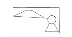
- the schematic diagram of the image for left eyes Lin for demonstrating the acquisition method of a depth map.
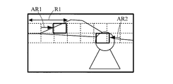
- the schematic diagram of the image Rin for right eyes for demonstrating the acquisition method of a depth map.
- the schematic diagram of the image for left eyes Lin for demonstrating the acquisition method of a depth map.
- the schematic diagram of the image Rin for right eyes for demonstrating the acquisition method of a depth map.
- the figure which shows an example of a depth map typically.
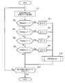
- FIG. 6 is a flowchart of depth map correction processing executed by the depth map correction unit 2; The flowchart of the correction process (pt) of the depth map correction process performed in the depth map correction
- FIG. The table
- FIG. The figure which shows the two-dimensional data arrangement
- FIG. The figure which shows the two-dimensional data arrangement
- FIG. The figure which shows the two-dimensional data arrangement
- FIG. 1 is a schematic configuration diagram of a stereoscopic image processing apparatus 1000 according to the first embodiment.
- the stereoscopic image processing apparatus 1000 includes a depth map generation unit 1, a depth map correction unit 2, and an image processing unit 3, as shown in FIG.
- the depth map generation unit 1 receives the right-eye image Rin and the left-eye image Lin that form a stereoscopic image (stereo image), and inputs either the right-eye image Rin or the left-eye image Lin.
- the image is set as a standard image, and the other image is set as a reference image.
- the depth map generation unit 1 divides the standard image into blocks of a predetermined size (blocks composed of a plurality of pixels), and on the reference image corresponding to the divided blocks (hereinafter referred to as “divided blocks”).
- a matching process for specifying the position is executed.
- the depth map generator 1 executes this matching process for all the divided blocks.
- the depth map generation unit 1 detects a parallax (depth value) for all the divided blocks on the reference image by performing a matching process, and maps the detected parallax (depth value) to the position of the corresponding divided block. And get the depth map. Then, the depth map generation unit 1 outputs the acquired depth map to the depth map correction unit 2.
- the depth map correction unit 2 takes the depth map acquired by the depth map generation unit 1 as input, and determines whether or not to be a correction target block for each divided block with respect to the input depth map. For a divided block determined to be a correction target block, the depth value is corrected for each pixel included in the divided block (details will be described later).
- the depth map correction unit 2 outputs the depth map acquired by executing the above correction processing on the depth map acquired by the depth map generation unit 1 to the image processing unit 3 as a correction depth map.
- the image processing unit 3 receives the right-eye image Rin and the left-eye image Lin that form a stereoscopic image (stereo image) and the corrected depth map acquired by the depth map correcting unit 2.
- the image processing unit 3 performs a desired operation on the right-eye image Rin and / or the left-eye image Lin based on the depth value (distance information) for each pixel (or each block) acquired from the correction depth map. Perform image processing. Then, the image processing unit 3 outputs the right-eye image and the left-eye image after the image processing as the right-eye output image Rout and the left-eye output image Lout.
- FIG. 2 is a schematic diagram for explaining a depth map acquisition method.
- FIG. 2A is a left-eye image Lin.
- FIG. 2B is the right-eye image Rin.
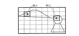
- FIG. 2C is a diagram illustrating a relationship (an example) between a divided block set on the left-eye image Lin and a search region.
- FIG. 2D is a diagram for describing parallax (depth value) acquired by matching processing on the right-eye image Rin.
- FIG. 2E is a diagram for explaining the depth map.
- the right-eye image Rin and the left-eye image Lin that form a stereoscopic image are input to the depth map generation unit 1.
- either one of the input right-eye image Rin and left-eye image Lin is set as a reference image, and the other image is set as a reference image.
- the left-eye image Lin is set as a reference image
- the right-eye image Rin is set as a reference image.
- the method for setting the standard image and the reference image may be the reverse of the above.
- the left-eye image Lin which is a reference image
- the left-eye image Lin is divided into blocks of a predetermined size (blocks composed of a plurality of pixels), and the divided blocks (hereinafter, “ Matching processing is executed using the right-eye image Rin that is a reference image for each “divided block”.
- the divided block is a block composed of n pixels ⁇ m pixels (n, m: natural number)
- the depth map generation unit 1 on the right-eye image Rin that is a reference image has a predetermined left and right range (horizontal direction centered on the same coordinate position as the divided block BL1 on the right-eye image Rin that is a reference image). (Predetermined range) is set in the search area.
- the search area of the divided block BL1 is the area indicated by the arrow R1.
- the search areas for the divided blocks shown in FIGS. 2C and 2D are merely examples, and the search areas are not limited to this, and search areas of other sizes may be set.
- the depth map generation unit 1 detects, in the set search region, an image region that is most similar to the divided block BL1 on the left-eye image Lin on the right-eye image Rin.
- the depth map generation unit 1 shifts a rectangular area of n pixels ⁇ m pixels (a rectangular area having the same size as the divided block) to the left and right in the search area on the right-eye image Rin.
- a region having the highest degree of coincidence with the divided block on the eye image Lin is detected.
- the degree of coincidence is the same as the pixel value of each pixel included in the divided block BL1 and the pixel value of each pixel included in a rectangular area (search block) consisting of n pixels ⁇ m pixels (relative position in the area (block)). It is calculated
- SAD Sud of Absolute Difference
- the coordinate of the upper left pixel of the divided block BL1 is (x0, y0)
- the pixel value of the pixel at the coordinate (x, y) included in the divided block BL1 is S (x, y)
- n pixels ⁇ m The coordinates of the upper left pixel of the rectangular area (search block) made up of pixels are (x1, y1), and the pixel value of the pixel at coordinates (x, y) included in the search block is D (x, y).
- the SAD value is obtained by the following (Formula 1).
- the depth map generation unit 1 detects a position where the SAD value (matching degree) calculated by the above (Equation 1) is the smallest in the search region on the right-eye image Rin, and detects the detected position (right-eye image
- the amount of deviation (the amount of deviation in the horizontal direction) between the position on Rin) and the position of the divided block BL on the left-eye image Lin is detected as the parallax (depth value) of the divided block BL.
- the length of the arrow AR1 corresponds to the parallax (depth value) of the divided block BL.
- the depth map generation unit 1 may calculate the degree of coincidence by using an SSD (Sum of Squared Difference) value instead of the SAD value. Good.
- 2D corresponds to the length of the arrow AR2 shown in FIG. 2D by performing the same processing in the search region corresponding to the arrow R2 shown in FIG. 2C for the divided block BL2 shown in FIG. 2C.
- the value is acquired as the parallax (depth value) of the divided block BL2.
- the disparity (depth value) of the divided block BL1 is a positive value ⁇ ( ⁇ > 0), and the disparity (depth value) of the divided block BL2 is a negative value ⁇ ( ⁇ > 0). That is, when the stereoscopic image shown in FIGS. 2A and 2B is displayed as a stereoscopic image, the subject corresponding to the divided block BL1 is located farther away from the virtual screen (the position where the parallax is “0”), and is displayed on the divided block BL2. The corresponding subject is localized in front of the virtual screen.
- the parallax (depth value) of each divided block is acquired.
- generation part 1 acquires a depth map by mapping the acquired parallax (depth value) to the position on the image of each division
- the depth map is not necessarily held as image data, and any depth map may be used as long as it can be held in a data format in which the relationship between each divided block and the parallax (depth value) of the divided block is known.
- the depth map acquired by the depth map generation unit 1 is output to the depth map correction unit 2.
- the depth map correction unit 2 determines whether or not the input depth map should be a correction target block for each division block, and determines the division block determined to be the correction target block. On the other hand, depth value correction is performed for each pixel included in the divided block.
- FIG. 3 shows an example of the depth map.
- the depth map in FIG. 3 is an example of a depth map corresponding to a part of an image area of one image (for example, one frame image).
- the numerical value in each divided block in FIG. 3 indicates the depth value of each divided block, and as an example, the depth value is in the range of ⁇ 128 to 127.
- FIG. 3 shows a case in which the depth map has a format that holds a depth value for each pixel. That is, in FIG. 3, one divided block is configured by 8 pixels ⁇ 8 pixels, and the same depth value (depth value of the divided block) is set to all the pixels (64 pixels) in each divided block. Shows the case. As shown in FIG. 3, for example, the depth values of all the pixels (64 pixels) included in the divided block whose depth value is “ ⁇ 82” are each set to “ ⁇ 82”.
- the pattern shown in FIG. 4 is applied to the depth map, thereby determining whether or not the division block to be processed should be the correction target block.
- FIG. 4 is a diagram showing four patterns for detecting whether or not an oblique boundary region is included in a divided block.
- FIG. 4 shows nine 3 ⁇ 3 divided blocks, and the central divided block is a block to be processed.
- pattern 1 the depth value (parallax) of the divided blocks adjacent to the lower and right sides of the processing target divided block (center divided block) (hereinafter referred to as “target block”) is a predetermined threshold value.
- target block the depth value of the divided block adjacent to the upper and left sides of the block of interest is larger than a predetermined threshold. That is, pattern 1 is a pattern for detecting an image region in which the lower right region is a foreground and the upper left region is a distant view.
- Pattern 2 shown in FIG. 4B shows that the depth values (parallax) of the divided blocks adjacent to the lower side and the left side of the target block are smaller than a predetermined threshold value, and It shows a case where the depth value is larger than a predetermined threshold value. That is, the pattern 2 is a pattern for detecting an image region in which the lower left region is a foreground and the upper right region is a distant view.
- the depth values (disparity) of the divided blocks adjacent to the upper and left sides of the target block are smaller than a predetermined threshold, and the divided blocks adjacent to the lower and right sides of the target block are displayed. It shows a case where the depth value is larger than a predetermined threshold value. That is, the pattern 3 is a pattern for detecting an image region in which the upper left region is a foreground and the lower right region is a distant view.
- the depth values (parallax) of the divided blocks adjacent to the upper and right sides of the target block are smaller than a predetermined threshold, and the divided blocks adjacent to the lower and left sides of the target block are displayed. It shows a case where the depth value is larger than a predetermined threshold value. That is, the pattern 4 is a pattern for detecting an image region in which the upper right region is a foreground and the lower left region is a distant view.
- the “predetermined threshold value” is preferably set such that occurrence of side effects such as jaggies is sufficiently suppressed when stereoscopic image processing is performed.
- the threshold value may be changed depending on the situation of the target depth map. For example, a method for creating a table for determining threshold values from the entire depth map, or a method for determining threshold values by introducing an algorithm for determining foreground objects (such as people) from the foreground shape on the image to be processed is adopted.
- the threshold value may be determined.
- the depth map correction unit 2 selects a divided block (target block) as a processing target block in the input depth map (step S1).
- step S10 it is determined whether the target block satisfies the condition of pattern 2 shown in FIG.
- the depth map correction unit 2 advances the process to step S8.
- step S8 it is determined whether the target block satisfies the condition of the pattern 4 shown in FIG.
- step S11 when the determination result in step S8 is “No”, or after the process of step S10 is executed, the depth map correction unit 2 determines whether there is an unprocessed divided block, and the unprocessed block. If there is a divided block, the process returns to S1, and if there is no unprocessed divided block, the process is completed.
- the above processing is executed for all the divided blocks of the depth map.
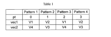
- step S101 the depth map correction unit 2 determines the value vec1 and the value vec2 from the table 1 shown in FIG. 7A based on the value of the variable pt indicating the corresponding pattern.
- Table 1 shown in FIG. 7A shows a value vec1 and a value vec2 set by the value pt.
- the values V1 to V4 are V1 when the depth value of the divided block adjacent to the divided block to be processed (the block indicated by “Vec” in FIG. 7B) is V1.
- the depth value of the divided block adjacent to the left is V2
- the depth value of the divided block adjacent to the right of the processing target divided block is V3
- step S102 the depth map correction unit 2 sets the value of y to “0”.
- the value of y is a value indicating a row of a two-dimensional data array for correcting the depth value of each pixel in the divided block.
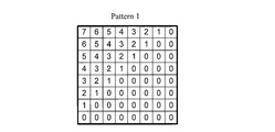
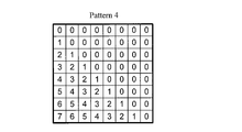
- FIGS. 8A to 8D are the two-dimensional data array shown in FIGS. 8A to 8D.
- FIG. 8A is a two-dimensional data array for correcting the depth value of each pixel in the divided block in the case of pattern 1.
- FIG. 8B is a two-dimensional data array for correcting the depth value of each pixel in the divided block in the case of pattern 2.
- FIG. 8C is a two-dimensional data array for correcting the depth value of each pixel in the divided block in the case of pattern 3.
- FIG. 8D is a two-dimensional data array for correcting the depth value of each pixel in the divided block in the case of the pattern 4.
- FIGS. 8A to 8D is an example when one divided block is composed of 8 pixels ⁇ 8 pixels.
- step S103 the depth map correction unit 2 sets the value of x to “0”.
- the value of x is a value indicating a column of a two-dimensional data array for correcting the depth value of each pixel in the divided block.
- step S ⁇ b> 104 the depth map correction unit 2 determines a coefficient k for correcting the depth value of the pixel to be processed (hereinafter referred to as “target pixel”).
- target pixel a coefficient k for correcting the depth value of the pixel to be processed
- k pattern_tbl [pt] [y] [x]
- the correction coefficient k is determined.
- pattern_tbl [pt] [y] [x] is a value determined by a variable pt indicating a pattern satisfied by the division block to be processed and a relative coordinate position (x, y) in the division block of the target pixel. Specifically, it is as follows.
- pattern_tbl [0] [y] [x] is data at the position (x, y) in the two-dimensional array shown in FIG. 8A.
- pattern_tbl [1] [y] [x] is data at the position (x, y) in the two-dimensional array shown in FIG. 8B.
- the correction coefficient k is determined by pattern_tbl [2] [y] [x]. That is, pattern_tbl [2] [y] [x] is data at the position (x, y) in the two-dimensional array shown in FIG. 8C.
- the correction coefficient k is determined by pattern_tbl [3] [y] [x]. That is, pattern_tbl [3] [y] [x] is data at the position (x, y) in the two-dimensional array shown in FIG. 8D.
- step S105 the depth map correction unit 2 uses the correction coefficient k determined in step S104 to calculate the depth value correction value Vec of the target pixel according to the following equation.
- Vec (k ⁇ vec1 + (8 ⁇ k) ⁇ vec2) / 8 Specifically, the depth value correction value Vec is calculated for each pattern as shown in the following (1) to (4).
- the correction coefficient k becomes larger as it goes to the upper left (a value closer to “8”), and goes to the lower right. It is set to be a small value (a value close to “0”).
- the coefficient k is a numerical value that determines the internal ratio, and therefore, the closer to the upper left in the divided block, the closer to the depth value V1 of the adjacent divided block above the target block. On the contrary, the lower the right, the closer to the depth value V4 of the divided block adjacent to the target block.
- the depth correction value Vec of the target pixel is calculated.
- the correction coefficient k becomes larger as it goes to the lower left (a value closer to “8”) and becomes smaller as it goes to the upper right. It is set to be a value (a value close to “0”).
- the coefficient k is a numerical value that determines the internal ratio, so that the lower the left in the divided block, the closer to the depth value V2 of the divided block adjacent to the left of the target block. On the contrary, as it goes to the upper right, it takes a value closer to the depth value V3 of the divided block adjacent to the right of the target block.
- the depth correction value Vec of the target pixel is calculated.
- the correction coefficient k becomes larger as it goes to the upper left (a value closer to “8”), and goes to the lower right. It is set to be a small value (a value close to “0”).
- the coefficient k is a numerical value that determines the internal ratio, and therefore, the closer to the upper left in the divided block, the closer to the depth value V1 of the adjacent divided block above the target block. On the contrary, the lower the right, the closer to the depth value V4 of the divided block adjacent to the target block.
- the depth correction value Vec of the target pixel is calculated.
- the correction coefficient k becomes larger as it goes to the lower left (a value closer to “8”), and becomes smaller as it goes to the upper right. It is set to be a value (a value close to “0”).
- the coefficient k is a numerical value that determines the internal ratio, so that the lower the left in the divided block, the closer to the depth value V2 of the divided block adjacent to the left of the target block. On the contrary, as it goes to the upper right, it takes a value closer to the depth value V3 of the divided block adjacent to the right of the target block.
- the depth correction value of this pixel is the value V3.
- the depth value of the divided block on the right side of the block of interest is small (that is, the area on the right side of the block of interest is a foreground)
- the depth value with emphasis on the foreground is obtained by the two-dimensional data array shown in FIG. Correction processing can be executed.
- the depth value correction value Vec of the target pixel is calculated by the above (1) to (4), and the depth value of the target pixel is replaced with the correction value Vec.
- step S106 In step S106, the value of x is incremented by “1”.
- step S107 it is determined whether the value of x is smaller than “8”. If the value of x is smaller than “8”, the processing of steps S104 to S106 is repeatedly executed. On the other hand, when the value of x is “8” or more, the depth map correction unit 2 advances the process to step S108.
- step S108 In step S108, the value of y is incremented by “1”.
- step S109 it is determined whether the value of y is smaller than “8”. If the value of y is smaller than “8”, the process returns to step S103, and the process of step S103 is repeatedly executed. On the other hand, when the value of y is “8” or more, the depth map correction unit 2 advances the process to step S11 (completes the correction process of the depth value of each pixel in the divided block determined to be corrected).
- the depth map correction unit can appropriately correct the depth value according to the state of the boundary in the block of interest by executing the above process. That is, the depth map correction unit executes the processing as described in (1) to (4) below.
- (1) In the case of pattern 1, that is, when there is a high possibility that there is a boundary in the upper right direction (a region where the depth value is greatly different) in the target block, and there is a foreground in the lower right region of the target block, The depth map correction unit corrects the depth value of the pixel in the lower right region in the block of interest so that it is closer to the foreground (corrects the depth value of the divided block below the block of interest), and The depth value of the pixel in the upper left area in the block is corrected so as to become a distant view (corrected to approach the depth value of the upper divided block of the target block).
- the map correction unit corrects the depth value of the pixel in the lower left region in the block of interest so that it is closer to the background (corrects the depth value of the divided block on the left side of the block of interest), and The depth value of the pixel in the upper right region is corrected so as to become a distant view (corrected so as to approach the depth value of the divided block on the right side of the block of interest).
- the map correction unit corrects the depth value of the pixel in the upper left area in the block of interest so that it is closer to the foreground (corrects the depth value of the divided block above the block of interest), and The depth value of the pixel in the lower right region is corrected so as to become a distant view (corrected so as to approach the depth value of the divided block below the block of interest).
- the map correction unit corrects the depth value of the pixel in the upper right region in the block of interest so that it is closer to the foreground (corrects the depth value of the divided block on the right side of the block of interest), and The depth value of the pixel in the lower left region is corrected so as to be a distant view (corrected so as to approach the depth value of the divided block on the left side of the target block).
- the depth map correction unit can appropriately correct the depth value according to the state of the boundary in the block of interest by executing the processing as described in (1) to (4) above.
- the above processing is executed by the depth map correction unit 2, and the corrected depth map (corrected depth map) is output to the image processing unit 3.
- a desired value for the right-eye image Rin and / or the left-eye image Lin is obtained based on the depth value (distance information) for each pixel (or for each block) acquired from the corrected depth map.
- Image processing is executed.
- the image processing unit 3 uses the corrected depth map in which the depth value is appropriately corrected by the depth map correction unit 2 for the pixels in the divided blocks including the diagonal boundary, and the right eye image Rin and / or the left eye. Image processing can be executed on the image for use Lin.
- the image processing unit 3 performs a parallax conversion process, a process of adjusting a pixel value by a depth value (for example, a contrast adjustment process), or the like for the right-eye image Rin and / or the left-eye image Lin.
- a depth value for example, a contrast adjustment process
- the depth value is acquired by performing the matching process in units of blocks, and the depth acquired in units of blocks is obtained for blocks that do not include boundaries in the divided blocks.
- High-speed processing can be realized by performing stereoscopic image processing using values.
- the depth is obtained in units of pixels with respect to the depth value obtained by performing matching processing in units of blocks in the block. The value is corrected, and the three-dimensional image processing is performed for the block using the corrected depth value.
- the depth map is acquired with a small amount of calculation by performing the matching process in units of blocks, and the depth value in the divided block is included only when the boundary is included in the divided block. Correct appropriately. Therefore, the stereoscopic image processing apparatus 1000 can realize high-speed processing and can execute highly accurate stereoscopic image processing that effectively suppresses the occurrence of side effects such as jaggy.
- the size of the divided block is 8 pixels ⁇ 8 pixels has been described.
- the size of the divided block is not limited to this, and may be other sizes.
- the present invention is not limited to this.
- an area having a size smaller than that of the divided block for example, an area of 2 pixels ⁇ 2 pixels when the size of the divided block is 8 pixels ⁇ 8 pixels
- the set area unit for example, 2 pixels
- the depth value may be corrected in a region of ⁇ 2 pixels.
- the stereoscopic image processing apparatus of the above embodiment is mounted on, for example, a display device, an imaging device, a video transmission / reception device, a video recording / playback device, and the like.
- a part or all of the stereoscopic image processing apparatus according to the above-described embodiment may be realized as an integrated circuit (for example, an LSI, a system LSI, or the like).
- Part or all of the processing of each functional block in the above embodiment may be realized by a program.
- a part or all of the processing of each functional block in the above embodiment is performed by a central processing unit (CPU) in the computer.
- a program for performing each processing is stored in a storage device such as a hard disk or a ROM, and is read out and executed in the ROM or the RAM.
- each process of the above embodiment may be realized by hardware, or may be realized by software (including a case where it is realized together with an OS (operating system), middleware, or a predetermined library). Further, it may be realized by mixed processing of software and hardware.
- OS operating system
- middleware middleware
- predetermined library predetermined library
- execution order of the processing methods in the above embodiment is not necessarily limited to the description of the above embodiment, and the execution order can be changed without departing from the gist of the invention.
- a computer program that causes a computer to execute the above-described method and a computer-readable recording medium that records the program are included in the scope of the present invention.
- the computer-readable recording medium include a flexible disk, a hard disk, a CD-ROM, an MO, a DVD, a DVD-ROM, a DVD-RAM, a BD (Blu-ray Disc), and a semiconductor memory. .
- the computer program is not limited to the one recorded on the recording medium, but may be transmitted via a telecommunication line, a wireless or wired communication line, a network represented by the Internet, or the like.
- the stereoscopic image processing apparatus having the first configuration is a stereoscopic image processing apparatus including a depth map generation unit and a depth map correction unit.
- the depth map generation unit acquires a depth value in units of blocks including a plurality of pixels using the first viewpoint image and the second viewpoint image, and generates a depth map.
- the depth map correction unit determines whether or not the boundary block is included in the block of interest based on the depth value of the block around the block of interest that is the block to be processed on the depth map. If it is determined that the boundary area is included, the depth value is corrected in a correction area unit that is a unit smaller than the block in the target block.
- the depth map is generated by acquiring the depth value in units of blocks including a plurality of pixels, so that the depth map can be acquired with a small amount of calculation. Furthermore, in this stereoscopic image processing apparatus, when a boundary area (area where the depth value differs greatly) is included in the block of interest, the depth value is corrected in a correction area unit which is a unit smaller than the block, so the depth value is used. Thus, when performing stereoscopic image processing, it is possible to execute highly accurate stereoscopic image processing.
- the “first viewpoint image” is, for example, an image captured from the first viewpoint (for example, an image for the right eye), and the “second viewpoint image” is, for example, a viewpoint different from the first viewpoint. It is the image (for example, image for left eyes) imaged from the 2nd viewpoint.
- the “correction area which is a unit smaller than the block” means an area included in the block and smaller than the size of the block. For example, when the block size is 8 ⁇ 8 pixels, "Is an area composed of 2 pixels x 2 pixels or an area composed of one pixel, for example.
- the “depth map” refers to data in which a position on an image is associated with a depth value of the position, and may be, for example, data in a two-dimensional image format (distance image).
- on the depth image has the same meaning as “on the distance image” when a two-dimensional image format distance image is generated based on the data constituting the depth map.
- the depth map correction unit performs the following processes (1) to (4).
- a depth value of an upper adjacent block that is a block adjacent to the upper side of the target block and a depth value of a left adjacent block that is a block adjacent to the left side of the target block are both at predetermined positions.
- the depth value of the lower adjacent block that is the block adjacent to the lower side of the target block and the right side that is the block adjacent to the right side of the target block are both at predetermined positions.
- the depth value in the target block is expressed as the depth value of the upper adjacent block and the depth value of the lower adjacent block. Use to correct.
- the depth value of the upper adjacent block and the depth value of the right adjacent block are both values that are farther from the first position on the depth map, and the depth of the left adjacent block on the depth map.
- the depth value in the target block is determined by using the depth value of the left adjacent block and the depth value of the right adjacent block. ,to correct.
- the depth value in the target block is used as the depth value of the upper adjacent block and the depth value of the lower adjacent block. Correct.
- the depth value in the target block is determined using the depth value of the left adjacent block and the depth value of the right adjacent block. ,to correct.
- the depth value in the target block is corrected using the depth values of two adjacent blocks adjacent to both sides of the target block in accordance with the patterns (1) to (4). Therefore, in this stereoscopic image processing apparatus, there is a high possibility that there is a boundary area in the diagonally upper right direction in the target block, and the lower right portion in the target block is a foreground.
- the pattern (2) above when there is a high possibility that there is a boundary region in the upper left direction in the target block, and the lower left part in the target block may be a foreground
- the pattern of (3) above when there is a high possibility that there is a boundary region in the upper right direction in the block of interest, and there is a high possibility that the upper right part in the block of interest is a foreground
- the pattern of (4) above when there is a high possibility that there is a boundary region in the upper left direction in the target block, and there is a high possibility that the upper right part in the target block is a foreground
- the “value indicating being far from the first position” may include a value corresponding to the first position.
- the “value indicating closer to the second position” may include a value corresponding to the second position.
- the depth map correction unit performs the following processes (1) to (4).
- (1) On the depth map when the depth value of the upper adjacent block and the depth value of the left adjacent block are both values that are farther than the first position, and on the depth map, When the depth value and the depth value of the right adjacent block are both values closer to the second position, the depth value in the target block is set as the correction area in the target block is closer to the upper left end of the target block. Then, a value close to the depth value of the upper adjacent block is taken, and correction is performed so that the closer the position of the correction area in the target block is to the lower right end of the target block, the closer to the depth value of the lower adjacent block.
- the depth value in the target block is set as the correction area in the target block is closer to the lower left end of the target block.
- a value close to the depth value of the left adjacent block is taken, and correction is performed so that the value closer to the depth value of the right adjacent block is closer to the upper right end of the target block.
- the depth value in the target block is represented on the depth map using the depth values of two adjacent blocks adjacent to both sides of the target block according to the patterns (1) to (4). Is corrected so as to be close to the depth value of the adjacent block with the shorter distance. Therefore, in this stereoscopic image processing apparatus, the depth value in the block of interest can be corrected appropriately in any case of the patterns (1) to (4).
- the depth value in the target block is obtained by internal division processing of the depth values of two adjacent blocks adjacent to both sides of the target block, and the internal division coefficient of the internal division processing is calculated as a distance on the depth map. May be set so as to be close to the depth value of an adjacent block closer to.
- the “value indicating being far from the first position” may include a value corresponding to the first position.
- the “value indicating closer to the second position” may include a value corresponding to the second position.
- the correction area is an area composed of one pixel.
- the depth value in the block of interest can be corrected in units of one pixel.
- the stereoscopic image processing method as the first method is a stereoscopic image processing method including a depth map generation step and a depth map correction step.
- a depth value is acquired in units of blocks each including a plurality of pixels using the first viewpoint image and the second viewpoint image, and a depth map is generated.
- the depth map correction step determines whether or not the boundary block is included in the block of interest based on the depth value of the block around the block of interest that is the processing target block on the depth map. If it is determined that the boundary area is included, the depth value is corrected in a correction area unit that is a unit smaller than the block in the target block.
- the first program is a program that causes a computer to execute the stereoscopic image processing method.
- the stereoscopic image processing method includes a depth map generation step and a depth map correction step.
- a depth value is acquired in units of blocks each including a plurality of pixels using the first viewpoint image and the second viewpoint image, and a depth map is generated.
- the depth map correction step determines whether or not the boundary block is included in the block of interest based on the depth value of the block around the block of interest that is the processing target block on the depth map. If it is determined that the boundary area is included, the depth value is corrected in a correction area unit that is a unit smaller than the block in the target block.
- the stereoscopic image processing apparatus, the stereoscopic image processing method, and the program according to the present invention can obtain a depth map with a small amount of calculation and can execute highly accurate stereoscopic image processing, which is useful in the field of video equipment related industries. And can be implemented in the field.
Landscapes
- Engineering & Computer Science (AREA)
- Physics & Mathematics (AREA)
- General Physics & Mathematics (AREA)
- Theoretical Computer Science (AREA)
- Multimedia (AREA)
- Signal Processing (AREA)
- Computer Vision & Pattern Recognition (AREA)
- Testing, Inspecting, Measuring Of Stereoscopic Televisions And Televisions (AREA)
Abstract
少ない演算量で視差マップ(デプスマップ)を取得するとともに、精度の高い立体画像処理を実行することができる立体画像処理装置を実現する。立体画像処理装置(1000)は、デプスマップ生成部(1)と、デプスマップ補正部(2)と、を備える。デプスマップ生成部(1)は、第1視点用画像および第2視点用画像を用いて、複数の画素からなるブロック単位でデプス値を取得し、デプスマップを生成する。デプスマップ補正部(2)は、デプスマップ上において、処理対象のブロックである注目ブロックの周辺のブロックのデプス値に基づいて、注目ブロック内に境界領域が含まれるか否かの判定を行うとともに、注目ブロック内に境界領域が含まれると判定された場合、注目ブロック内において、ブロックより小さい単位である補正領域単位でデプス値を補正する。
Description
本発明は、立体画像処理技術に関する。特に、立体画像(ステレオ画像)を処理する場合に用いられるデプスマップ(距離画像)の補正に関する。
異なる視点により取得された右眼用画像および左眼用画像からなる立体画像(ステレオ画像)に対して、距離情報を用いて様々な処理を行う技術がある。
距離情報を用いて立体画像に対して処理を行う場合、例えば、右眼用画像および左眼用画像から視差マップ(デプスマップ)を取得し、取得した視差マップ(デプスマップ)を用いて、立体画像に対して処理を行う。
具体的には、右眼用画像および左眼用画像のうちの一方の画像を基準画像とし、当該基準画像の画素ごとに、対応する他方の画像(基準画像ではない画像)の画素との水平方向のズレ量である視差を算出し、算出した視差を当該視差に対応する画素の位置(画像上の位置)にマッピングすることで、1画面分の視差マップ(デプスマップ)を取得することができる。そして、取得した視差マップ(デプスマップ)を用いることで、画素ごとの距離情報(デプス値)が取得できるので、処理対象画素に対して、距離情報(デプス値)に応じた様々な処理を行うことができる。
例えば、特許文献1に開示されているように、視差マップ(デプスマップ)を用いることで、オクルージョン領域を検出することや、オクルージョン領域の視差の補正を行うことができる。
しかしながら、視差マップ(デプスマップ)を取得する場合、画素ごとに、視差を算出すると演算量が多くなり、高速な処理を行うことができない。
そこで、複数の画素からなるブロックごとに視差を算出することで、視差マップ(デプスマップ)を少ない演算量で取得し、高速な処理を実現させることが考えられる。
ブロックごとに視差を算出して取得した視差マップ(デプスマップ)を用いて、立体画像に対する処理を行う場合、高速な処理を実現することができるが、同一ブロック内に視差が大きく異なる画素が含まれていた場合(例えば、前景と背景との境界が同一ブロック内に含まれている場合)、当該ブロックに含まれる画素に対して、視差マップから取得した視差あるいは距離情報(デプス値)を用いて、処理を行うと適切な処理が実行されないことがある。このような場合、処理結果の立体画像において、当該ブロック(視差(デプス値)が大きく異なる画素が含まれるブロック)内にジャギーが発生する等の副作用が生じることがある。
そこで、本発明は、上記課題に鑑み、少ない演算量で視差マップ(デプスマップ)を取得するとともに、精度の高い立体画像処理を実行することができる立体画像処理装置、立体処理方法、および、プログラムを実現することを目的とする。
上記課題を解決するために、第1の構成の立体画像処理装置は、デプスマップ生成部と、デプスマップ補正部と、を備える立体画像処理装置である。
デプスマップ生成部は、第1視点用画像および第2視点用画像を用いて、複数の画素からなるブロック単位でデプス値を取得し、デプスマップを生成する。
デプスマップ補正部は、デプスマップ上において、処理対象のブロックである注目ブロックの周辺のブロックのデプス値に基づいて、注目ブロック内に境界領域が含まれるか否かの判定を行うとともに、注目ブロック内に境界領域が含まれると判定された場合、注目ブロック内において、ブロックより小さい単位である補正領域単位でデプス値を補正する。
本発明によれば、少ない演算量で視差マップ(デプスマップ)を取得するとともに、精度の高い立体画像処理を実行することができる立体画像処理装置、立体処理方法、および、プログラムを実現することができる。
[第1実施形態]
第1実施形態について、図面を参照しながら、以下、説明する。
第1実施形態について、図面を参照しながら、以下、説明する。
<1.1:立体画像処理装置の構成>
図1は、第1実施形態に係る立体画像処理装置1000の概略構成図である。
図1は、第1実施形態に係る立体画像処理装置1000の概略構成図である。
立体画像処理装置1000は、図1に示すように、デプスマップ生成部1と、デプスマップ補正部2と、画像処理部3と、を備える。
デプスマップ生成部1は、立体画像(ステレオ画像)を構成する右眼用画像Rinおよび左眼用画像Linを入力とし、入力された右眼用画像Rinおよび左眼用画像Linのいずれか一方の画像を基準画像に設定し、他方の画像を参照画像に設定する。そして、デプスマップ生成部1は、基準画像を所定の大きさのブロック(複数の画素からなるブロック)に分割し、分割したブロック(以下、「分割ブロック」という。)に対応する参照画像上の位置を特定するマッチング処理を実行する。デプスマップ生成部1は、このマッチング処理を全ての分割ブロックについて実行する。デプスマップ生成部1は、マッチング処理を行うことで、基準画像上の全ての分割ブロックについて視差(デプス値)を検出し、検出した視差(デプス値)を対応する分割ブロックの位置にマッピングすることで、デプスマップを取得する。そして、デプスマップ生成部1は、取得したデプスマップをデプスマップ補正部2に出力する。
デプスマップ補正部2は、デプスマップ生成部1により取得されたデプスマップを入力とし、入力されたデプスマップに対して、分割ブロックごとに、補正対象ブロックとするべきか否かの判定を行い、補正対象ブロックとするべきであると判定された分割ブロックに対して、当該分割ブロック内に含まれる画素ごとに、デプス値を補正する(詳細については、後述)。デプスマップ補正部2は、デプスマップ生成部1により取得されたデプスマップに対して、上記補正処理を実行することで取得したデプスマップを補正デプスマップとして、画像処理部3に出力する。
画像処理部3は、立体画像(ステレオ画像)を構成する右眼用画像Rinおよび左眼用画像Linと、デプスマップ補正部2により取得された補正デプスマップとを入力とする。画像処理部3は、補正デプスマップから取得される画素ごと(あるいはブロックごと)のデプス値(距離情報)に基づいて、右眼用画像Rinおよび/または左眼用画像Linに対して、所望の画像処理を実行する。そして、画像処理部3は、画像処理後の右眼用画像および左眼画像を、右眼用出力画像Routおよび左眼用出力画像Loutとして、出力する。
<1.2:立体画像処理装置の動作>
以上のように構成された立体画像処理装置1000の動作について、以下、説明する。
以上のように構成された立体画像処理装置1000の動作について、以下、説明する。
図2は、デプスマップの取得方法を説明するための模式図である。図2Aは、左眼用画像Linである。図2Bは、右眼用画像Rinである。図2Cは、左眼用画像Lin上に設定された分割ブロックと探索領域との関係(一例)を示す図である。図2Dは、右眼用画像Rin上において、マッチング処理により取得される視差(デプス値)について説明するための図である。図2Eは、デプスマップを説明するための図である。
以下では、図2Aに示す左眼用画像Linおよび図2Bに示す右眼用画像Rinが立体画像処理装置1000に入力された場合について説明する。
まず、立体画像(ステレオ画像)を構成する右眼用画像Rinおよび左眼用画像Linがデプスマップ生成部1に入力される。
デプスマップ生成部1では、入力された右眼用画像Rinおよび左眼用画像Linのいずれか一方の画像が基準画像に設定され、他方の画像が参照画像に設定される。以下では、説明便宜のため、左眼用画像Linが基準画像として設定され、右眼用画像Rinが参照画像として設定された場合について説明する。なお、基準画像および参照画像の設定方法は、上記と逆であってもよい。
デプスマップ生成部1では、図2Cに示すように、基準画像である左眼用画像Linが所定の大きさのブロック(複数の画素からなるブロック)に分割され、分割されたブロック(以下、「分割ブロック」という。)ごとに参照画像である右眼用画像Rinを用いてマッチング処理が実行される。なお、以下では、分割ブロックは、n画素×m画素(n,m:自然数)からなるブロックである場合について説明する。
ここで、図2Cに示す、左眼用画像Lin上の分割ブロックBL1を処理対象とした場合のマッチング処理について説明する。
デプスマップ生成部1は、参照画像である右眼用画像Rin上において、基準画像である右眼用画像Rin上の分割ブロックBL1と同じ座標位置を中心とする左右の所定の範囲(水平方向の所定の範囲)を探索領域に設定する。図2C、図2Dの場合、分割ブロックBL1の探索領域は、矢印R1で示した領域である。なお、図2C、図2Dに示した分割ブロックの探索領域は一例であり、これに限定されることはなく、他の大きさの探索領域を設定してもよい。
デプスマップ生成部1は、右眼用画像Rin上において、左眼用画像Lin上の分割ブロックBL1と最も類似する画像領域を、設定した探索領域において検出する。
具体的には、デプスマップ生成部1は、右眼用画像Rin上の探索領域内において、n画素×m画素からなる矩形領域(分割ブロックと同じサイズの矩形領域)を左右にずらしながら、左眼用画像Lin上の分割ブロックと最も一致度の高い領域を検出する。一致度は、分割ブロックBL1に含まれる各画素の画素値と、n画素×m画素からなる矩形領域(探索用ブロック)に含まれる各画素の画素値(領域(ブロック)内の相対位置が同じ画素の画素値)との差の絶対値の総和であるSAD(Sum of Absolute Difference)値により求められる。つまり、分割ブロックBL1の左上の画素の座標を(x0,y0)とし、分割ブロックBL1に含まれる、座標(x,y)の画素の画素値をS(x,y)とし、n画素×m画素からなる矩形領域(探索用ブロック)の左上の画素の座標を(x1,y1)とし、探索用ブロックに含まれる、座標(x,y)の画素の画素値をD(x,y)とすると、SAD値は、下記(数式1)により求められる。

デプスマップ生成部1は、右眼用画像Rin上の探索領域内において、上記(数式1)により算出したSAD値(一致度)が最も小さくなる位置を検出し、検出した位置(右眼用画像Rin上の位置)と、左眼用画像Lin上の分割ブロックBLの位置とのズレ量(水平方向のズレ量)を、分割ブロックBLの視差(デプス値)として検出する。図2Dの場合、矢印AR1の長さが分割ブロックBLの視差(デプス値)に相当する。なお、本実施形態では、右方向にずれている場合の視差(デプス値)は正の値をとり、左方向にずれている場合の視差(デプス値)は負の値をとるものとする。なお、上記では、SAD値を用いる場合について説明しているが、SAD値の代わりにSSD(Sum of Squared Difference)値を用いて、デプスマップ生成部1は、一致度を算出するようにしてもよい。
デプスマップ生成部1は、図2Cの分割ブロックBL2についても、図2Cに示す矢印R2に相当する探索領域において、上記同様の処理を行うことにより、図2Dに示す矢印AR2の長さに相当する値を分割ブロックBL2の視差(デプス値)として取得する。
図2A~図2Dの場合、分割ブロックBL1の視差(デプス値)は、正の値α(α>0)であり、分割ブロックBL2の視差(デプス値)は、負の値-β(β>0)である。つまり、図2A、図2Bに示す立体画像を立体画像表示させた場合、分割ブロックBL1に対応する被写体は、仮想スクリーン(視差が「0」の位置)よりも奥に定位し、分割ブロックBL2に対応する被写体は、仮想スクリーンよりも手前に定位する。
以上で説明したマッチング処理を、全ての分割ブロックに対して実行することで、各分割ブロックの視差(デプス値)が取得される。そして、デプスマップ生成部1は、取得した視差(デプス値)を各分割ブロックの画像上の位置にマッピングすることで、デプスマップを取得する。例えば、図2Eに示すように、分割ブロックBL1の位置に、マッチング処理により取得された視差(デプス値)「+α」を、分割ブロックBL2の位置に、マッチング処理により取得された視差(デプス値)「-β」を、それぞれ、マッピングすることで、デプスマップが取得される。なお、デプスマップは、必ずしも画像データとして保持される必要はなく、各分割ブロックと、当該分割ブロックの視差(デプス値)との関係が分かるデータ形式で保持されるものであればよい。
以上のようにして、デプスマップ生成部1で取得されたデプスマップは、デプスマップ補正部2に出力される。
デプスマップ補正部2は、入力されたデプスマップに対して、分割ブロックごとに、補正対象ブロックとするべきか否かの判定を行い、補正対象ブロックとするべきであると判定された分割ブロックに対して、当該分割ブロック内に含まれる画素ごとに、デプス値補正する。
図3に、デプスマップの一例を示す。なお、図3のデプスマップは、1枚の画像(例えば、1フレーム画像)の一部の画像領域に対応するデプスマップの一例である。図3の各分割ブロックの中の数値は、各分割ブロックのデプス値を示しており、一例として、デプス値が-128~127の範囲の値である場合を示している。また、図3は、デプスマップが画素ごとにデプス値を保持する形式である場合を示している。つまり、図3は、1つの分割ブロックが8画素×8画素から構成されており、各分割ブロック内の全て画素(64個の画素)に、同じデプス値(分割ブロックのデプス値)が設定されている場合を示している。図3に示すように、例えば、デプス値が「-82」の分割ブロックに含まれる全ての画素(64個の画素)のデプス値は、それぞれ、「-82」に設定されている。
デプスマップ補正部2では、デプスマップに対して、図4に示すパターンを適用することで、処理対象の分割ブロックを補正対象ブロックとするべきか否かの判定処理が実行される。
図4は、分割ブロック内に斜め方向の境界領域が含まれているか否かを検出するための4つのパターンを示す図である。図4は、3×3の9個の分割ブロックを示しており、中心の分割ブロックが処理対象のブロックである。
図4(a)に示すパターン1は、処理対象分割ブロック(中央の分割ブロック)(以下、「注目ブロック」という。)の下および右に隣接する分割ブロックのデプス値(視差)が所定の閾値よりも小さく、かつ、注目ブロックの上および左に隣接する分割ブロックのデプス値が所定の閾値よりも大きい場合を示している。つまり、パターン1は、右下領域が近景であり、左上領域が遠景であるような画像領域を検出するためのパターンである。
図4(b)に示すパターン2は、注目ブロックの下および左に隣接する分割ブロックのデプス値(視差)が所定の閾値よりも小さく、かつ、注目ブロックの上および右に隣接する分割ブロックのデプス値が所定の閾値よりも大きい場合を示している。つまり、パターン2は、左下領域が近景であり、右上領域が遠景であるような画像領域を検出するためのパターンである。
図4(c)に示すパターン3は、注目ブロックの上および左に隣接する分割ブロックのデプス値(視差)が所定の閾値よりも小さく、かつ、注目ブロックの下および右に隣接する分割ブロックのデプス値が所定の閾値よりも大きい場合を示している。つまり、パターン3は、左上領域が近景であり、右下領域が遠景であるような画像領域を検出するためのパターンである。
図4(d)に示すパターン4は、注目ブロックの上および右に隣接する分割ブロックのデプス値(視差)が所定の閾値よりも小さく、かつ、注目ブロックの下および左に隣接する分割ブロックのデプス値が所定の閾値よりも大きい場合を示している。つまり、パターン4は、右上領域が近景であり、左下領域が遠景であるような画像領域を検出するためのパターンである。
なお、上記の「所定の閾値」は、立体画像処理を行った場合に、ジャギー等の副作用の発生が十分に抑制されるように設定されることが好ましい。閾値は、対象となるデプスマップの状況により変化させるようにしてもよい。例えば、デプスマップ全体から、閾値を決定するテーブルを作成する方法や、処理対処の画像上の前景の形状から前景のオブジェクト(人物など)を判断するアルゴリズムを導入して閾値を判断する手法を採用し、閾値を決定するようにしてもよい。
ここで、図5および図6に示すフローチャートを用いて、デプスマップ補正部2で実行されるデプスマップ補正処理について説明する。
(S1):
デプスマップ補正部2は、入力されたデプスマップにおいて、処理対象ブロックとする分割ブロック(注目ブロック)を選択する(ステップS1)。
デプスマップ補正部2は、入力されたデプスマップにおいて、処理対象ブロックとする分割ブロック(注目ブロック)を選択する(ステップS1)。
≪パターン判定処理≫
(S2~S9):
(1)ステップS2にて、ステップS1で選択された注目ブロックが、図4に示すパターン1の条件を満たすか判定される。つまり、注目ブロックの上および左に隣接する分割ブロックのデプス値が所定の閾値th1よりも大きく、かつ、注目ブロックの下および右に隣接する分割ブロックのデプス値が所定の閾値th2より小さい場合(パターン1の条件)(ステップS2において「Yes」)、デプスマップ補正部2は、注目ブロックがパターン1の条件を満たすと判定し、変数ptをpt=0にセットする(ステップS3)。そして、注目ブロックに対してパターン1の場合、すなわち、pt=0の場合の補正処理(ステップS10の処理)が実行される(ステップS10の補正処理については後述)。一方、上記パターン1の条件を満たさない場合(ステップS2において「No」)、デプスマップ補正部2は、処理をステップ4に進める。
(2)ステップS4にて、注目ブロックが、図4に示すパターン2の条件を満たすか判定される。つまり、注目ブロックの上および右に隣接する分割ブロックのデプス値が所定の閾値th1よりも大きく、かつ、注目ブロックの下および左に隣接する分割ブロックのデプス値が所定の閾値th2より小さい場合(パターン2の条件)(ステップS4において「Yes」)、デプスマップ補正部2は、注目ブロックがパターン2の条件を満たすと判定し、変数ptをpt=1にセットする(ステップS5)。そして、注目ブロックに対してパターン2の場合、すなわち、pt=1の場合の補正処理(ステップS10の処理)が実行される(ステップS10の補正処理については後述)。一方、上記パターン2の条件を満たさない場合(ステップS4において「No」)、デプスマップ補正部2は、処理をステップS6に進める。
(3)ステップS6にて、注目ブロックが、図4に示すパターン3の条件を満たすか判定される。つまり、注目ブロックの下および右に隣接する分割ブロックのデプス値が所定の閾値th1よりも大きく、かつ、注目ブロックの上および左に隣接する分割ブロックのデプス値が所定の閾値th2より小さい場合(パターン3の条件)(ステップS6において「Yes」)、デプスマップ補正部2は、注目ブロックがパターン3の条件を満たすと判定し、変数ptをpt=2にセットする(ステップS7)。そして、注目ブロックに対してパターン3の場合、すなわち、pt=2の場合の補正処理(ステップS10の処理)が実行される(ステップS10の補正処理については後述)。一方、上記パターン3の条件を満たさない場合(ステップS6において「No」)、デプスマップ補正部2は、処理をステップS8に進める。
(4)ステップS8にて、注目ブロックが、図4に示すパターン4の条件を満たすか判定される。つまり、注目ブロックの下および左に隣接する分割ブロックのデプス値が所定の閾値th1よりも大きく、かつ、注目ブロックの上および右に隣接する分割ブロックのデプス値が所定の閾値th2より小さい場合(パターン4の条件)(ステップS8において「Yes」)、デプスマップ補正部2は、注目ブロックがパターン4の条件を満たすと判定し、変数ptをpt=3にセットする(ステップS9)。そして、注目ブロックに対してパターン4の場合、すなわち、pt=3の場合の補正処理(ステップS10の処理)が実行される(ステップS10の補正処理については後述)。一方、上記パターン4の条件を満たさない場合(ステップS6において「No」)、デプスマップ補正部2は、処理をステップS11に進める。
(S2~S9):
(1)ステップS2にて、ステップS1で選択された注目ブロックが、図4に示すパターン1の条件を満たすか判定される。つまり、注目ブロックの上および左に隣接する分割ブロックのデプス値が所定の閾値th1よりも大きく、かつ、注目ブロックの下および右に隣接する分割ブロックのデプス値が所定の閾値th2より小さい場合(パターン1の条件)(ステップS2において「Yes」)、デプスマップ補正部2は、注目ブロックがパターン1の条件を満たすと判定し、変数ptをpt=0にセットする(ステップS3)。そして、注目ブロックに対してパターン1の場合、すなわち、pt=0の場合の補正処理(ステップS10の処理)が実行される(ステップS10の補正処理については後述)。一方、上記パターン1の条件を満たさない場合(ステップS2において「No」)、デプスマップ補正部2は、処理をステップ4に進める。
(2)ステップS4にて、注目ブロックが、図4に示すパターン2の条件を満たすか判定される。つまり、注目ブロックの上および右に隣接する分割ブロックのデプス値が所定の閾値th1よりも大きく、かつ、注目ブロックの下および左に隣接する分割ブロックのデプス値が所定の閾値th2より小さい場合(パターン2の条件)(ステップS4において「Yes」)、デプスマップ補正部2は、注目ブロックがパターン2の条件を満たすと判定し、変数ptをpt=1にセットする(ステップS5)。そして、注目ブロックに対してパターン2の場合、すなわち、pt=1の場合の補正処理(ステップS10の処理)が実行される(ステップS10の補正処理については後述)。一方、上記パターン2の条件を満たさない場合(ステップS4において「No」)、デプスマップ補正部2は、処理をステップS6に進める。
(3)ステップS6にて、注目ブロックが、図4に示すパターン3の条件を満たすか判定される。つまり、注目ブロックの下および右に隣接する分割ブロックのデプス値が所定の閾値th1よりも大きく、かつ、注目ブロックの上および左に隣接する分割ブロックのデプス値が所定の閾値th2より小さい場合(パターン3の条件)(ステップS6において「Yes」)、デプスマップ補正部2は、注目ブロックがパターン3の条件を満たすと判定し、変数ptをpt=2にセットする(ステップS7)。そして、注目ブロックに対してパターン3の場合、すなわち、pt=2の場合の補正処理(ステップS10の処理)が実行される(ステップS10の補正処理については後述)。一方、上記パターン3の条件を満たさない場合(ステップS6において「No」)、デプスマップ補正部2は、処理をステップS8に進める。
(4)ステップS8にて、注目ブロックが、図4に示すパターン4の条件を満たすか判定される。つまり、注目ブロックの下および左に隣接する分割ブロックのデプス値が所定の閾値th1よりも大きく、かつ、注目ブロックの上および右に隣接する分割ブロックのデプス値が所定の閾値th2より小さい場合(パターン4の条件)(ステップS8において「Yes」)、デプスマップ補正部2は、注目ブロックがパターン4の条件を満たすと判定し、変数ptをpt=3にセットする(ステップS9)。そして、注目ブロックに対してパターン4の場合、すなわち、pt=3の場合の補正処理(ステップS10の処理)が実行される(ステップS10の補正処理については後述)。一方、上記パターン4の条件を満たさない場合(ステップS6において「No」)、デプスマップ補正部2は、処理をステップS11に進める。
(S11):
ステップS11では、ステップS8での判定結果が「No」の場合、または、ステップS10の処理が実行された後、デプスマップ補正部2は、未処理の分割ブロックがないか判定し、未処理の分割ブロックがある場合、処理をS1に戻し、未処理の分割ブロックがない場合、処理を完了させる。
ステップS11では、ステップS8での判定結果が「No」の場合、または、ステップS10の処理が実行された後、デプスマップ補正部2は、未処理の分割ブロックがないか判定し、未処理の分割ブロックがある場合、処理をS1に戻し、未処理の分割ブロックがない場合、処理を完了させる。
以上により、デプスマップの全ての分割ブロックに対して、上記処理が実行される。
≪デプス値の補正処理≫
ここで、ステップS10のパターンごとの補正処理について、図6のフローチャートを用いて説明する。
ここで、ステップS10のパターンごとの補正処理について、図6のフローチャートを用いて説明する。
(S101):
ステップS101にて、デプスマップ補正部2は、図7Aに示すテーブル1から、該当パターンを示す変数ptの値に基づいて、値vec1および値vec2を決定する。
ステップS101にて、デプスマップ補正部2は、図7Aに示すテーブル1から、該当パターンを示す変数ptの値に基づいて、値vec1および値vec2を決定する。
図7Aに示すテーブル1は、値ptにより設定される値vec1および値vec2を示している。例えば、pt=0(パターン1)の場合、
vec1=V1
vec2=V4
に設定される。値V1~V4は、図7Bに示すように、処理対象の分割ブロック(図7Bにおいて、「Vec」で示すブロック)の上に隣接する分割ブロックのデプス値がV1であり、処理対象の分割ブロックの左に隣接する分割ブロックのデプス値がV2であり、処理対象の分割ブロックの右に隣接する分割ブロックのデプス値がV3であり、処理対象の分割ブロックの下に隣接する分割ブロックのデプス値がV4である。
vec1=V1
vec2=V4
に設定される。値V1~V4は、図7Bに示すように、処理対象の分割ブロック(図7Bにおいて、「Vec」で示すブロック)の上に隣接する分割ブロックのデプス値がV1であり、処理対象の分割ブロックの左に隣接する分割ブロックのデプス値がV2であり、処理対象の分割ブロックの右に隣接する分割ブロックのデプス値がV3であり、処理対象の分割ブロックの下に隣接する分割ブロックのデプス値がV4である。
(S102):
ステップS102にて、デプスマップ補正部2は、yの値を「0」に設定する。なお、yの値は、分割ブロック内の各画素のデプス値を補正するための2次元データ配列の行を示す値である。具体的には、図8A~図8Dに示す2次元データ配列によりパターンごとの補正処理が実行される。図8Aは、パターン1の場合における分割ブロック内の各画素のデプス値を補正するための2次元データ配列である。図8Bは、パターン2の場合における分割ブロック内の各画素のデプス値を補正するための2次元データ配列である。図8Cは、パターン3の場合における分割ブロック内の各画素のデプス値を補正するための2次元データ配列である。図8Dは、パターン4の場合における分割ブロック内の各画素のデプス値を補正するための2次元データ配列である。
ステップS102にて、デプスマップ補正部2は、yの値を「0」に設定する。なお、yの値は、分割ブロック内の各画素のデプス値を補正するための2次元データ配列の行を示す値である。具体的には、図8A~図8Dに示す2次元データ配列によりパターンごとの補正処理が実行される。図8Aは、パターン1の場合における分割ブロック内の各画素のデプス値を補正するための2次元データ配列である。図8Bは、パターン2の場合における分割ブロック内の各画素のデプス値を補正するための2次元データ配列である。図8Cは、パターン3の場合における分割ブロック内の各画素のデプス値を補正するための2次元データ配列である。図8Dは、パターン4の場合における分割ブロック内の各画素のデプス値を補正するための2次元データ配列である。
なお、図8A~図8Dに示した2次元データ配列は、1つの分割ブロックが8画素×8画素からなる場合の一例である。
(S103):
ステップS103にて、デプスマップ補正部2は、xの値を「0」に設定する。なお、xの値は、分割ブロック内の各画素のデプス値を補正するための2次元データ配列の列を示す値である。
ステップS103にて、デプスマップ補正部2は、xの値を「0」に設定する。なお、xの値は、分割ブロック内の各画素のデプス値を補正するための2次元データ配列の列を示す値である。
(S104):
ステップS104にて、デプスマップ補正部2は、処理対象の画素(以下、「注目画素」という。)のデプス値を補正するための係数kを決定する。具体的には、
k=pattern_tbl[pt][y][x]
により、補正係数kを決定する。なお、pattern_tbl[pt][y][x]は、処理対象の分割ブロックが満たすパターンを示す変数pt、注目画素の分割ブロック内の相対座標位置(x,y)により決定される値である。具体的には、以下の通りである。
(1)処理対象の分割ブロックが満たすパターンがパターン1である場合、pattern_tbl[0][y][x]により、補正係数kが決定される。つまり、pattern_tbl[0][y][x]は、図8Aに示す2次元配列の(x,y)の位置のデータである。
(2)処理対象の分割ブロックが満たすパターンがパターン2である場合、pattern_tbl[1][y][x]により、補正係数kが決定される。つまり、pattern_tbl[1][y][x]は、図8Bに示す2次元配列の(x,y)の位置のデータである。
(3)処理対象の分割ブロックが満たすパターンがパターン3である場合、pattern_tbl[2][y][x]により、補正係数kが決定される。つまり、pattern_tbl[2][y][x]は、図8Cに示す2次元配列の(x,y)の位置のデータである。
(4)処理対象の分割ブロックが満たすパターンがパターン4である場合、pattern_tbl[3][y][x]により、補正係数kが決定される。つまり、pattern_tbl[3][y][x]は、図8Dに示す2次元配列の(x,y)の位置のデータである。
ステップS104にて、デプスマップ補正部2は、処理対象の画素(以下、「注目画素」という。)のデプス値を補正するための係数kを決定する。具体的には、
k=pattern_tbl[pt][y][x]
により、補正係数kを決定する。なお、pattern_tbl[pt][y][x]は、処理対象の分割ブロックが満たすパターンを示す変数pt、注目画素の分割ブロック内の相対座標位置(x,y)により決定される値である。具体的には、以下の通りである。
(1)処理対象の分割ブロックが満たすパターンがパターン1である場合、pattern_tbl[0][y][x]により、補正係数kが決定される。つまり、pattern_tbl[0][y][x]は、図8Aに示す2次元配列の(x,y)の位置のデータである。
(2)処理対象の分割ブロックが満たすパターンがパターン2である場合、pattern_tbl[1][y][x]により、補正係数kが決定される。つまり、pattern_tbl[1][y][x]は、図8Bに示す2次元配列の(x,y)の位置のデータである。
(3)処理対象の分割ブロックが満たすパターンがパターン3である場合、pattern_tbl[2][y][x]により、補正係数kが決定される。つまり、pattern_tbl[2][y][x]は、図8Cに示す2次元配列の(x,y)の位置のデータである。
(4)処理対象の分割ブロックが満たすパターンがパターン4である場合、pattern_tbl[3][y][x]により、補正係数kが決定される。つまり、pattern_tbl[3][y][x]は、図8Dに示す2次元配列の(x,y)の位置のデータである。
(S105):
ステップS105にて、デプスマップ補正部2は、ステップS104にて決定された補正係数kを用いて、以下の数式により、注目画素のデプス値の補正値Vecが算出される。
ステップS105にて、デプスマップ補正部2は、ステップS104にて決定された補正係数kを用いて、以下の数式により、注目画素のデプス値の補正値Vecが算出される。
Vec=(k×vec1+(8-k)×vec2)/8
具体的には、以下の(1)~(4)に示すようにして、パターンごとにデプス値の補正値Vecが算出される。
(1)パターン1の場合
処理対象の分割ブロックが満たすパターンがパターン1である場合、図7Aより、
vec1=V1(注目ブロックの上に隣接する分割ブロックのデプス値)、
vec2=V4(注目ブロックの下に隣接する分割ブロックのデプス値)
であるので、
Vec=(k×vec1+(8-k)×vec2)/8
=(k×V1+(8-k)×V4)/8
により、注目画素のデプス補正値Vecが算出される。処理対象の分割ブロックが満たすパターンがパターン1である場合、図8Aから分かるように、補正係数kは、左上にいく程、大きな値(「8」に近い値)となり、右下にいく程、小さな値(「0」に近い値)となるように設定されている。上記数式から分かるように、係数kは、内分比を決定する数値であるので、分割ブロック内において、左上にいく程、注目ブロックの上に隣接する分割ブロックのデプス値V1に近い値をとり、逆に、右下にいく程、注目ブロックの下に隣接する分割ブロックのデプス値V4に近い値をとることになる。
具体的には、以下の(1)~(4)に示すようにして、パターンごとにデプス値の補正値Vecが算出される。
(1)パターン1の場合
処理対象の分割ブロックが満たすパターンがパターン1である場合、図7Aより、
vec1=V1(注目ブロックの上に隣接する分割ブロックのデプス値)、
vec2=V4(注目ブロックの下に隣接する分割ブロックのデプス値)
であるので、
Vec=(k×vec1+(8-k)×vec2)/8
=(k×V1+(8-k)×V4)/8
により、注目画素のデプス補正値Vecが算出される。処理対象の分割ブロックが満たすパターンがパターン1である場合、図8Aから分かるように、補正係数kは、左上にいく程、大きな値(「8」に近い値)となり、右下にいく程、小さな値(「0」に近い値)となるように設定されている。上記数式から分かるように、係数kは、内分比を決定する数値であるので、分割ブロック内において、左上にいく程、注目ブロックの上に隣接する分割ブロックのデプス値V1に近い値をとり、逆に、右下にいく程、注目ブロックの下に隣接する分割ブロックのデプス値V4に近い値をとることになる。
また、図8Aの2次元データ配列の右斜め上方向の対角線より下側(右下側)のデータが「0」に設定されているので、注目ブロックの右斜め上方向の対角線より下側(右下側)の画素のデプス補正値が値V4となる。パターン1の場合、注目ブロックの下側の分割ブロックのデプス値が小さい(つまり、注目ブロックの下側の領域が近景である)ので、図8Aに示す2次元データ配列により、近景を重視したデプス値の補正処理が実行できる。
(2)パターン2の場合
処理対象の分割ブロックが満たすパターンがパターン2である場合、図7Aより、
vec1=V2(注目ブロックの左に隣接する分割ブロックのデプス値)、
vec2=V3(注目ブロックの右に隣接する分割ブロックのデプス値)
であるので、
Vec=(k×vec1+(8-k)×vec2)/8
=(k×V2+(8-k)×V3)/8
により、注目画素のデプス補正値Vecが算出される。処理対象の分割ブロックが満たすパターンがパターン2である場合、図8Bから分かるように、補正係数kは、左下にいく程、大きな値(「8」に近い値)となり、右上にいく程、小さな値(「0」に近い値)となるように設定されている。上記数式から分かるように、係数kは、内分比を決定する数値であるので、分割ブロック内において、左下にいく程、注目ブロックの左に隣接する分割ブロックのデプス値V2に近い値をとり、逆に、右上にいく程、注目ブロックの右に隣接する分割ブロックのデプス値V3に近い値をとることになる。
(2)パターン2の場合
処理対象の分割ブロックが満たすパターンがパターン2である場合、図7Aより、
vec1=V2(注目ブロックの左に隣接する分割ブロックのデプス値)、
vec2=V3(注目ブロックの右に隣接する分割ブロックのデプス値)
であるので、
Vec=(k×vec1+(8-k)×vec2)/8
=(k×V2+(8-k)×V3)/8
により、注目画素のデプス補正値Vecが算出される。処理対象の分割ブロックが満たすパターンがパターン2である場合、図8Bから分かるように、補正係数kは、左下にいく程、大きな値(「8」に近い値)となり、右上にいく程、小さな値(「0」に近い値)となるように設定されている。上記数式から分かるように、係数kは、内分比を決定する数値であるので、分割ブロック内において、左下にいく程、注目ブロックの左に隣接する分割ブロックのデプス値V2に近い値をとり、逆に、右上にいく程、注目ブロックの右に隣接する分割ブロックのデプス値V3に近い値をとることになる。
また、図8Bの2次元データ配列の左斜め上方向の対角線より下側(左下側)のデータが「7」に設定されているので、注目ブロックの左斜め上方向の対角線より下側(左下側)の画素のデプス補正値が値V2に近い値となる。パターン2の場合、注目ブロックの左側の分割ブロックのデプス値が小さい(つまり、注目ブロックの左側の領域が近景である)ので、図8Bに示す2次元データ配列により、近景を重視したデプス値の補正処理が実行できる。
(3)パターン3の場合
処理対象の分割ブロックが満たすパターンがパターン3である場合、図7Aより、
vec1=V1(注目ブロックの上に隣接する分割ブロックのデプス値)、
vec2=V4(注目ブロックの下に隣接する分割ブロックのデプス値)
であるので、
Vec=(k×vec1+(8-k)×vec2)/8
=(k×V1+(8-k)×V4)/8
により、注目画素のデプス補正値Vecが算出される。処理対象の分割ブロックが満たすパターンがパターン3である場合、図8Cから分かるように、補正係数kは、左上にいく程、大きな値(「8」に近い値)となり、右下にいく程、小さな値(「0」に近い値)となるように設定されている。上記数式から分かるように、係数kは、内分比を決定する数値であるので、分割ブロック内において、左上にいく程、注目ブロックの上に隣接する分割ブロックのデプス値V1に近い値をとり、逆に、右下にいく程、注目ブロックの下に隣接する分割ブロックのデプス値V4に近い値をとることになる。
(3)パターン3の場合
処理対象の分割ブロックが満たすパターンがパターン3である場合、図7Aより、
vec1=V1(注目ブロックの上に隣接する分割ブロックのデプス値)、
vec2=V4(注目ブロックの下に隣接する分割ブロックのデプス値)
であるので、
Vec=(k×vec1+(8-k)×vec2)/8
=(k×V1+(8-k)×V4)/8
により、注目画素のデプス補正値Vecが算出される。処理対象の分割ブロックが満たすパターンがパターン3である場合、図8Cから分かるように、補正係数kは、左上にいく程、大きな値(「8」に近い値)となり、右下にいく程、小さな値(「0」に近い値)となるように設定されている。上記数式から分かるように、係数kは、内分比を決定する数値であるので、分割ブロック内において、左上にいく程、注目ブロックの上に隣接する分割ブロックのデプス値V1に近い値をとり、逆に、右下にいく程、注目ブロックの下に隣接する分割ブロックのデプス値V4に近い値をとることになる。
また、図8Cの2次元データ配列の右斜め上方向の対角線より上側(左上側)のデータが「7」に設定されているので、注目ブロックの右斜め上方向の対角線より上側(左上側)の画素のデプス補正値が値V1に近い値となる。パターン3の場合、注目ブロックの上側の分割ブロックのデプス値が小さい(つまり、注目ブロックの上側の領域が近景である)ので、図8Cに示す2次元データ配列により、近景を重視したデプス値の補正処理が実行できる。
(4)パターン4の場合
処理対象の分割ブロックが満たすパターンがパターン4である場合、図7Aより、
vec1=V2(注目ブロックの左に隣接する分割ブロックのデプス値)、
vec2=V3(注目ブロックの右に隣接する分割ブロックのデプス値)
であるので、
Vec=(k×vec1+(8-k)×vec2)/8
=(k×V2+(8-k)×V3)/8
により、注目画素のデプス補正値Vecが算出される。処理対象の分割ブロックが満たすパターンがパターン4である場合、図8Dから分かるように、補正係数kは、左下にいく程、大きな値(「8」に近い値)となり、右上にいく程、小さな値(「0」に近い値)となるように設定されている。上記数式から分かるように、係数kは、内分比を決定する数値であるので、分割ブロック内において、左下にいく程、注目ブロックの左に隣接する分割ブロックのデプス値V2に近い値をとり、逆に、右上にいく程、注目ブロックの右に隣接する分割ブロックのデプス値V3に近い値をとることになる。
(4)パターン4の場合
処理対象の分割ブロックが満たすパターンがパターン4である場合、図7Aより、
vec1=V2(注目ブロックの左に隣接する分割ブロックのデプス値)、
vec2=V3(注目ブロックの右に隣接する分割ブロックのデプス値)
であるので、
Vec=(k×vec1+(8-k)×vec2)/8
=(k×V2+(8-k)×V3)/8
により、注目画素のデプス補正値Vecが算出される。処理対象の分割ブロックが満たすパターンがパターン4である場合、図8Dから分かるように、補正係数kは、左下にいく程、大きな値(「8」に近い値)となり、右上にいく程、小さな値(「0」に近い値)となるように設定されている。上記数式から分かるように、係数kは、内分比を決定する数値であるので、分割ブロック内において、左下にいく程、注目ブロックの左に隣接する分割ブロックのデプス値V2に近い値をとり、逆に、右上にいく程、注目ブロックの右に隣接する分割ブロックのデプス値V3に近い値をとることになる。
また、図8Dの2次元データ配列の左斜め上方向の対角線より上側(右上側)のデータが「0」に設定されているので、注目ブロックの左斜め上方向の対角線より上側(右上側)の画素のデプス補正値が値V3となる。パターン4の場合、注目ブロックの右側の分割ブロックのデプス値が小さい(つまり、注目ブロックの右側の領域が近景である)ので、図8Dに示す2次元データ配列により、近景を重視したデプス値の補正処理が実行できる。
以上のように、上記(1)~(4)により、注目画素のデプス値の補正値Vecが算出され、注目画素のデプス値が補正値Vecに置換される。
(S106):
ステップS106にて、xの値が「1」だけインクリメントされる。
ステップS106にて、xの値が「1」だけインクリメントされる。
(S107):
ステップS107にて、xの値が「8」より小さいか判定され、xの値が「8」より小さい場合、ステップS104~S106の処理が繰り返し実行される。一方、xの値が「8」以上の場合、デプスマップ補正部2は、処理をステップS108に進める。
ステップS107にて、xの値が「8」より小さいか判定され、xの値が「8」より小さい場合、ステップS104~S106の処理が繰り返し実行される。一方、xの値が「8」以上の場合、デプスマップ補正部2は、処理をステップS108に進める。
(S108):
ステップS108にて、yの値が「1」だけインクリメントされる。
ステップS108にて、yの値が「1」だけインクリメントされる。
(S109):
ステップS109にて、yの値が「8」より小さいか判定され、yの値が「8」より小さい場合、ステップS103に戻り、ステップS103移行の処理が繰り返し実行される。一方、yの値が「8」以上の場合、デプスマップ補正部2は、処理をステップS11に進める(補正対象と判定された分割ブロック内の各画素のデプス値の補正処理を完了させる)。
ステップS109にて、yの値が「8」より小さいか判定され、yの値が「8」より小さい場合、ステップS103に戻り、ステップS103移行の処理が繰り返し実行される。一方、yの値が「8」以上の場合、デプスマップ補正部2は、処理をステップS11に進める(補正対象と判定された分割ブロック内の各画素のデプス値の補正処理を完了させる)。
デプスマップ補正部では、上記処理を実行することにより、注目ブロック内の境界の状況に応じたデプス値の補正を適切に行うことができる。つまり、デプスマップ補正部では、以下の(1)~(4)にように処理を実行する。
(1)パターン1の場合、つまり、注目ブロック内に、右斜め上方向の境界(デプス値が大きく異なる領域)がある可能性が高く、かつ、注目ブロックの右下領域に近景がある場合、デプスマップ補正部は、注目ブロック内の右下領域の画素のデプス値をより近景となるように補正し(注目ブロックの下側の分割ブロックのデプス値に近づくように補正し)、かつ、注目ブロック内の左上領域の画素のデプス値をより遠景となるように補正する(注目ブロックの上側の分割ブロックのデプス値に近づくように補正する)。
(2)パターン2の場合、つまり、注目ブロック内に、左斜め上方向の境界(デプス値が大きく異なる領域)がある可能性が高く、かつ、注目ブロックの左下領域に近景がある場合、デプスマップ補正部は、注目ブロック内の左下領域の画素のデプス値をより近景となるように補正し(注目ブロックの左側の分割ブロックのデプス値に近づくように補正し)、かつ、注目ブロック内の右上領域の画素のデプス値をより遠景となるように補正する(注目ブロックの右側の分割ブロックのデプス値に近づくように補正する)。
(3)パターン3の場合、つまり、注目ブロック内に、右斜め上方向の境界(デプス値が大きく異なる領域)がある可能性が高く、かつ、注目ブロックの左上領域に近景がある場合、デプスマップ補正部は、注目ブロック内の左上領域の画素のデプス値をより近景となるように補正し(注目ブロックの上側の分割ブロックのデプス値に近づくように補正し)、かつ、注目ブロック内の右下領域の画素のデプス値をより遠景となるように補正する(注目ブロックの下側の分割ブロックのデプス値に近づくように補正する)。
(4)パターン4の場合、つまり、注目ブロック内に、左斜め上方向の境界(デプス値が大きく異なる領域)がある可能性が高く、かつ、注目ブロックの右上領域に近景がある場合、デプスマップ補正部は、注目ブロック内の右上領域の画素のデプス値をより近景となるように補正し(注目ブロックの右側の分割ブロックのデプス値に近づくように補正し)、かつ、注目ブロック内の左下領域の画素のデプス値をより遠景となるように補正する(注目ブロックの左側の分割ブロックのデプス値に近づくように補正する)。
(1)パターン1の場合、つまり、注目ブロック内に、右斜め上方向の境界(デプス値が大きく異なる領域)がある可能性が高く、かつ、注目ブロックの右下領域に近景がある場合、デプスマップ補正部は、注目ブロック内の右下領域の画素のデプス値をより近景となるように補正し(注目ブロックの下側の分割ブロックのデプス値に近づくように補正し)、かつ、注目ブロック内の左上領域の画素のデプス値をより遠景となるように補正する(注目ブロックの上側の分割ブロックのデプス値に近づくように補正する)。
(2)パターン2の場合、つまり、注目ブロック内に、左斜め上方向の境界(デプス値が大きく異なる領域)がある可能性が高く、かつ、注目ブロックの左下領域に近景がある場合、デプスマップ補正部は、注目ブロック内の左下領域の画素のデプス値をより近景となるように補正し(注目ブロックの左側の分割ブロックのデプス値に近づくように補正し)、かつ、注目ブロック内の右上領域の画素のデプス値をより遠景となるように補正する(注目ブロックの右側の分割ブロックのデプス値に近づくように補正する)。
(3)パターン3の場合、つまり、注目ブロック内に、右斜め上方向の境界(デプス値が大きく異なる領域)がある可能性が高く、かつ、注目ブロックの左上領域に近景がある場合、デプスマップ補正部は、注目ブロック内の左上領域の画素のデプス値をより近景となるように補正し(注目ブロックの上側の分割ブロックのデプス値に近づくように補正し)、かつ、注目ブロック内の右下領域の画素のデプス値をより遠景となるように補正する(注目ブロックの下側の分割ブロックのデプス値に近づくように補正する)。
(4)パターン4の場合、つまり、注目ブロック内に、左斜め上方向の境界(デプス値が大きく異なる領域)がある可能性が高く、かつ、注目ブロックの右上領域に近景がある場合、デプスマップ補正部は、注目ブロック内の右上領域の画素のデプス値をより近景となるように補正し(注目ブロックの右側の分割ブロックのデプス値に近づくように補正し)、かつ、注目ブロック内の左下領域の画素のデプス値をより遠景となるように補正する(注目ブロックの左側の分割ブロックのデプス値に近づくように補正する)。
このように、デプスマップ補正部では、上記(1)~(4)のように処理を実行することにより、注目ブロック内の境界の状況に応じたデプス値の補正を適切に行うことができる。
デプスマップ補正部2で、上記処理が実行され、補正されたデプスマップ(補正デプスマップ)は、画像処理部3に出力される。
画像処理部3では、補正デプスマップから取得される画素ごと(あるいはブロックごと)のデプス値(距離情報)に基づいて、右眼用画像Rinおよび/または左眼用画像Linに対して、所望の画像処理が実行される。画像処理部3では、斜め方向の境界を含む分割ブロック内の画素について、デプスマップ補正部2によりデプス値が適切に補正された補正デプスマップを用いて、右眼用画像Rinおよび/または左眼用画像Linに対して、画像処理を実行することができる。したがって、例えば、画像処理部3にて、右眼用画像Rinおよび/または左眼用画像Linに対して、視差変換処理や、デプス値により画素値を調整する処理(例えば、コントラスト調整処理)等を行う場合、ブロック単位でデプス値を取得したデプスマップ(補正処理を行っていないデプスマップ)を用いて処理したときに生じるジャギー等の副作用の発生を効果的に抑制することができる。
以上のように、本実施形態の立体画像処理装置1000では、ブロック単位でマッチング処理を行うことで、デプス値を取得し、分割ブロック内に境界を含まないブロックについては、ブロック単位で取得したデプス値を用いて、立体画像処理を行うことで、高速な処理を実現することができる。また、立体画像処理装置1000では、分割ブロック内に境界を含む可能性の高いブロックについては、当該ブロック内において、ブロック単位でマッチング処理を行うことで取得したデプス値に対して、画素単位でデプス値の補正を行い、当該ブロックについては、補正されたデプス値を用いて、立体画像処理を行う。つまり、本実施形態の立体画像処理装置1000では、ブロック単位でマッチング処理を行うことで少ない演算量でデプスマップを取得し、分割ブロック内に境界が含まれる場合のみ、当該分割ブロック内のデプス値を適切に補正する。したがって、立体画像処理装置1000では、高速処理を実現することができるとともに、ジャギー等の副作用の発生を効果的に抑制した精度の高い立体画像処理を実行することができる。
[他の実施形態]
上記実施形態では、分割ブロックのサイズが8画素×8画素の場合について説明したが、分割ブロックのサイズは、これに限定されることはなく、他のサイズであってもよい。
上記実施形態では、分割ブロックのサイズが8画素×8画素の場合について説明したが、分割ブロックのサイズは、これに限定されることはなく、他のサイズであってもよい。
また、上記実施形態では、境界領域を含む分割ブロックについて、画素単位でデプス値を補正する場合に説明したが、これに限定されることはない。例えば、分割ブロックよりも小さい大きさの領域(例えば、分割ブロックの大きさが8画素×8画素の場合、2画素×2画素の領域)を設定し、当該設定した領域単位(例えば、2画素×2画素の領域)でデプス値の補正を行うようにしてもよい。
また、上記実施形態の立体画像処理装置は、例えば、表示装置、撮像装置、映像送受信装置、映像記録再生装置等に搭載される。また、上記実施形態の立体画像処理装置の一部または全部は、集積回路(例えば、LSI、システムLSI等)として実現されるものであってもよい。
上記実施形態の各機能ブロックの処理の一部または全部は、プログラムにより実現されるものであってもよい。そして、上記実施形態の各機能ブロックの処理の一部または全部は、コンピュータにおいて、中央演算装置(CPU)により行われる。また、それぞれの処理を行うためのプログラムは、ハードディスク、ROMなどの記憶装置に格納されており、ROMにおいて、あるいはRAMに読み出されて実行される。
また、上記実施形態の各処理をハードウェアにより実現してもよいし、ソフトウェア(OS(オペレーティングシステム)、ミドルウェア、あるいは、所定のライブラリとともに実現される場合を含む。)により実現してもよい。さらに、ソフトウェアおよびハードウェアの混在処理により実現しても良い。
また、上記実施形態における処理方法の実行順序は、必ずしも、上記実施形態の記載に制限されるものではなく、発明の要旨を逸脱しない範囲で、実行順序を入れ替えることができるものである。
前述した方法をコンピュータに実行させるコンピュータプログラム及びそのプログラムを記録したコンピュータ読み取り可能な記録媒体は、本発明の範囲に含まれる。ここで、コンピュータ読み取り可能な記録媒体としては、例えば、フレキシブルディスク、ハードディスク、CD-ROM、MO、DVD、DVD-ROM、DVD-RAM、BD(Blu-ray Disc)、半導体メモリを挙げることができる。
上記コンピュータプログラムは、上記記録媒体に記録されたものに限られず、電気通信回線、無線又は有線通信回線、インターネットを代表とするネットワーク等を経由して伝送されるものであってもよい。
なお、本発明の具体的な構成は、前述の実施形態に限られるものではなく、発明の要旨を逸脱しない範囲で種々の変更および修正が可能である。
[付記]
なお、本発明は、以下のようにも表現することができる。
なお、本発明は、以下のようにも表現することができる。
第1の構成の立体画像処理装置は、デプスマップ生成部と、デプスマップ補正部と、を備える立体画像処理装置である。
デプスマップ生成部は、第1視点用画像および第2視点用画像を用いて、複数の画素からなるブロック単位でデプス値を取得し、デプスマップを生成する。
デプスマップ補正部は、デプスマップ上において、処理対象のブロックである注目ブロックの周辺のブロックのデプス値に基づいて、注目ブロック内に境界領域が含まれるか否かの判定を行うとともに、注目ブロック内に境界領域が含まれると判定された場合、注目ブロック内において、ブロックより小さい単位である補正領域単位でデプス値を補正する。
この立体画像処理装置では、複数の画素からなるブロック単位でデプス値を取得することでデプスマップを生成するので、少ない演算量でデプスマップを取得することができる。さらに、この立体画像処理装置では、注目ブロック内に境界領域(デプス値が大きく異なる領域)が含まれる場合に、ブロックより小さい単位である補正領域単位でデプス値を補正するので、デプス値を用いて立体画像処理を行う場合等において、精度の高い立体画像処理を実行することができる。
なお、「第1視点画像」とは、例えば、第1視点から撮像された画像(例えば、右眼用画像)であり、「第2視点画像」とは、例えば、第1視点とは異なる視点である第2視点から撮像された画像(例えば、左眼用画像)である。
また、「ブロックより小さい単位である補正領域」とは、ブロック内に含まれ、当該ブロックのサイズより小さい領域のことをいい、例えば、ブロックのサイズが8画素×8画素の場合、「補正領域」は、例えば、2画素×2画素からなる領域や、1画素からなる領域である。
また、「デプスマップ」とは、画像上の位置と当該位置のデプス値とが対応付けられたデータのことをいい、例えば、2次元画像形式のデータ(距離画像)としてもよい。
また、「デプスマップ上」とは、デプスマップを構成するデータに基づいて2次元画像形式の距離画像を生成した場合の当該「距離画像上」と同様の意味である。
第2の構成の立体画像処理装置は、第1の構成において、デプスマップ補正部は、以下の(1)~(4)の処理を行う。
(1)デプスマップ上において、注目ブロックの上側に隣接するブロックである上側隣接ブロックのデプス値および注目ブロックの左側に隣接するブロックである左側隣接ブロックのデプス値がともに所定の位置である第1の位置より遠いことを示す値である場合で、かつ、デプスマップ上において、注目ブロックの下側に隣接するブロックである下側隣接ブロックのデプス値および注目ブロックの右側に隣接するブロックである右側隣接ブロックのデプス値がともに所定の位置である第2の位置より近いことを示す値である場合、注目ブロック内のデプス値を、上側隣接ブロックのデプス値と下側隣接ブロックのデプス値とを用いて、補正する。
(2)デプスマップ上において、上側隣接ブロックのデプス値および右側隣接ブロックのデプス値がともに第1の位置より遠いことを示す値である場合で、かつ、デプスマップ上において、左側隣接ブロックのデプス値および下側隣接ブロックのデプス値がともに第2の位置より近いことを示す値である場合、注目ブロック内のデプス値を、左側隣接ブロックのデプス値と右側隣接ブロックのデプス値とを用いて、補正する。
(3)デプスマップ上において、下側隣接ブロックのデプス値および右側隣接ブロックのデプス値がともに第1の位置より遠いことを示す値である場合で、かつ、デプスマップ上において、左側隣接ブロックのデプス値および上側隣接ブロックのデプス値がともに第2の位置より近いことを示す値である場合、注目ブロック内のデプス値を、上側隣接ブロックのデプス値と下側隣接ブロックのデプス値とを用いて、補正する。
(4)デプスマップ上において、左側隣接ブロックのデプス値および下側隣接ブロックのデプス値がともに第1の位置より遠いことを示す値である場合で、かつ、デプスマップ上において、上側隣接ブロックのデプス値および右側隣接ブロックのデプス値がともに第2の位置より近いことを示す値である場合、注目ブロック内のデプス値を、左側隣接ブロックのデプス値と右側隣接ブロックのデプス値とを用いて、補正する。
(1)デプスマップ上において、注目ブロックの上側に隣接するブロックである上側隣接ブロックのデプス値および注目ブロックの左側に隣接するブロックである左側隣接ブロックのデプス値がともに所定の位置である第1の位置より遠いことを示す値である場合で、かつ、デプスマップ上において、注目ブロックの下側に隣接するブロックである下側隣接ブロックのデプス値および注目ブロックの右側に隣接するブロックである右側隣接ブロックのデプス値がともに所定の位置である第2の位置より近いことを示す値である場合、注目ブロック内のデプス値を、上側隣接ブロックのデプス値と下側隣接ブロックのデプス値とを用いて、補正する。
(2)デプスマップ上において、上側隣接ブロックのデプス値および右側隣接ブロックのデプス値がともに第1の位置より遠いことを示す値である場合で、かつ、デプスマップ上において、左側隣接ブロックのデプス値および下側隣接ブロックのデプス値がともに第2の位置より近いことを示す値である場合、注目ブロック内のデプス値を、左側隣接ブロックのデプス値と右側隣接ブロックのデプス値とを用いて、補正する。
(3)デプスマップ上において、下側隣接ブロックのデプス値および右側隣接ブロックのデプス値がともに第1の位置より遠いことを示す値である場合で、かつ、デプスマップ上において、左側隣接ブロックのデプス値および上側隣接ブロックのデプス値がともに第2の位置より近いことを示す値である場合、注目ブロック内のデプス値を、上側隣接ブロックのデプス値と下側隣接ブロックのデプス値とを用いて、補正する。
(4)デプスマップ上において、左側隣接ブロックのデプス値および下側隣接ブロックのデプス値がともに第1の位置より遠いことを示す値である場合で、かつ、デプスマップ上において、上側隣接ブロックのデプス値および右側隣接ブロックのデプス値がともに第2の位置より近いことを示す値である場合、注目ブロック内のデプス値を、左側隣接ブロックのデプス値と右側隣接ブロックのデプス値とを用いて、補正する。
この立体画像処理装置では、上記(1)~(4)のパターンに応じて、注目ブロックの両側に隣接する2つの隣接ブロックのデプス値を用いて、注目ブロック内のデプス値を補正する。したがって、この立体画像処理装置では、上記(1)のパターン(注目ブロック内において、右斜め上方向に境界領域がある可能性が高い場合であって、注目ブロック内の右下部分が近景である可能性が高い場合)、上記(2)のパターン(注目ブロック内において、左斜め上方向に境界領域がある可能性が高い場合であって、注目ブロック内の左下部分が近景である可能性が高い場合)、上記(3)のパターン(注目ブロック内において、右斜め上方向に境界領域がある可能性が高い場合であって、注目ブロック内の右上部分が近景である可能性が高い場合)、および、上記(4)のパターン(注目ブロック内において、左斜め上方向に境界領域がある可能性が高い場合であって、注目ブロック内の右上部分が近景である可能性が高い場合)、のいずれの場合であっても、注目ブロック内のデプス値を適切に補正することができる。
なお、「第1の位置より遠いことを示す値」とは、第1の位置に相当する値を含んでもよい。
また、「第2の位置より近いことを示す値」とは、第2の位置に相当する値を含んでもよい。
第3の構成の立体画像処理装置は、第2の構成において、デプスマップ補正部は、以下の(1)~(4)の処理を行う。
(1)デプスマップ上において、上側隣接ブロックのデプス値および左側隣接ブロックのデプス値がともに第1の位置より遠いことを示す値である場合で、かつ、デプスマップ上において、下側隣接ブロックのデプス値および右側隣接ブロックのデプス値がともに第2の位置より近いことを示す値である場合、注目ブロック内のデプス値を、注目ブロック内の補正領域の位置が注目ブロックの左上端に近い程、上側隣接ブロックのデプス値に近い値をとり、注目ブロック内の補正領域の位置が注目ブロックの右下端に近い程、下側隣接ブロックのデプス値に近い値をとるように補正する。
(2)デプスマップ上において、上側隣接ブロックのデプス値および右側隣接ブロックのデプス値がともに第1の位置より遠いことを示す値である場合で、かつ、デプスマップ上において、左側隣接ブロックのデプス値および下側隣接ブロックのデプス値がともに第2の位置より近いことを示す値である場合、注目ブロック内のデプス値を、注目ブロック内の補正領域の位置が注目ブロックの左下端に近い程、左側隣接ブロックのデプス値に近い値をとり、注目ブロック内の補正領域の位置が注目ブロックの右上端に近い程、右側隣接ブロックのデプス値に近い値をとるように補正する。
(3)デプスマップ上において、下側隣接ブロックのデプス値および右側隣接ブロックのデプス値がともに第1の位置より遠いことを示す値である場合で、かつ、デプスマップ上において、左側隣接ブロックのデプス値および上側隣接ブロックのデプス値がともに第2の位置より近いことを示す値である場合、注目ブロック内のデプス値を、注目ブロック内の補正領域の位置が注目ブロックの右上端に近い程、上側隣接ブロックのデプス値に近い値をとり、注目ブロック内の補正領域の位置が注目ブロックの右下端に近い程、下側隣接ブロックのデプス値に近い値をとるように補正する。
(4)デプスマップ上において、左側隣接ブロックのデプス値および下側隣接ブロックのデプス値がともに第1の位置より遠いことを示す値である場合で、かつ、デプスマップ上において、上側隣接ブロックのデプス値および右側隣接ブロックのデプス値がともに第2の位置より近いことを示す値である場合、注目ブロック内のデプス値を、注目ブロック内の補正領域の位置が注目ブロックの左下端に近い程、左側隣接ブロックのデプス値に近い値をとり、注目ブロック内の補正領域の位置が注目ブロックの右上端に近い程、右側隣接ブロックのデプス値に近い値をとるように補正する。
(1)デプスマップ上において、上側隣接ブロックのデプス値および左側隣接ブロックのデプス値がともに第1の位置より遠いことを示す値である場合で、かつ、デプスマップ上において、下側隣接ブロックのデプス値および右側隣接ブロックのデプス値がともに第2の位置より近いことを示す値である場合、注目ブロック内のデプス値を、注目ブロック内の補正領域の位置が注目ブロックの左上端に近い程、上側隣接ブロックのデプス値に近い値をとり、注目ブロック内の補正領域の位置が注目ブロックの右下端に近い程、下側隣接ブロックのデプス値に近い値をとるように補正する。
(2)デプスマップ上において、上側隣接ブロックのデプス値および右側隣接ブロックのデプス値がともに第1の位置より遠いことを示す値である場合で、かつ、デプスマップ上において、左側隣接ブロックのデプス値および下側隣接ブロックのデプス値がともに第2の位置より近いことを示す値である場合、注目ブロック内のデプス値を、注目ブロック内の補正領域の位置が注目ブロックの左下端に近い程、左側隣接ブロックのデプス値に近い値をとり、注目ブロック内の補正領域の位置が注目ブロックの右上端に近い程、右側隣接ブロックのデプス値に近い値をとるように補正する。
(3)デプスマップ上において、下側隣接ブロックのデプス値および右側隣接ブロックのデプス値がともに第1の位置より遠いことを示す値である場合で、かつ、デプスマップ上において、左側隣接ブロックのデプス値および上側隣接ブロックのデプス値がともに第2の位置より近いことを示す値である場合、注目ブロック内のデプス値を、注目ブロック内の補正領域の位置が注目ブロックの右上端に近い程、上側隣接ブロックのデプス値に近い値をとり、注目ブロック内の補正領域の位置が注目ブロックの右下端に近い程、下側隣接ブロックのデプス値に近い値をとるように補正する。
(4)デプスマップ上において、左側隣接ブロックのデプス値および下側隣接ブロックのデプス値がともに第1の位置より遠いことを示す値である場合で、かつ、デプスマップ上において、上側隣接ブロックのデプス値および右側隣接ブロックのデプス値がともに第2の位置より近いことを示す値である場合、注目ブロック内のデプス値を、注目ブロック内の補正領域の位置が注目ブロックの左下端に近い程、左側隣接ブロックのデプス値に近い値をとり、注目ブロック内の補正領域の位置が注目ブロックの右上端に近い程、右側隣接ブロックのデプス値に近い値をとるように補正する。
この立体画像処理装置では、上記(1)~(4)のパターンに応じて、注目ブロックの両側に隣接する2つの隣接ブロックのデプス値を用いて、注目ブロック内のデプス値を、デプスマップ上の距離が近い方の隣接ブロックのデプス値に近くなるように補正する。したがって、この立体画像処理装置では、上記(1)~(4)のパターンのいずれの場合であっても、注目ブロック内のデプス値を適切に補正することができる。
なお、注目ブロックの両側に隣接する2つの隣接ブロックのデプス値を用いて、注目ブロック内のデプス値を、デプスマップ上の距離が近い方の隣接ブロックのデプス値に近くなるように補正するために、以下のように処理するようにしてもよい。すなわち、注目ブロック内のデプス値を、注目ブロックの両側に隣接する2つの隣接ブロックのデプス値の内分処理により求めるようにし、さらに、当該内分処理の内分係数を、デプスマップ上の距離が近い方の隣接ブロックのデプス値に近くなるように設定するようにしてもよい。
なお、「第1の位置より遠いことを示す値」とは、第1の位置に相当する値を含んでもよい。
また、「第2の位置より近いことを示す値」とは、第2の位置に相当する値を含んでもよい。
第4の構成の立体画像処理装置は、第1から第3のいずれかの構成において、補正領域は、1画素からなる領域である。
これにより、この立体画像処理装置では、注目ブロック内のデプス値を、1画素単位で、補正することができる。
第1の方法である立体画像処理方法は、デプスマップ生成ステップと、デプスマップ補正ステップと、を備える立体画像処理方法である。
デプスマップ生成ステップは、第1視点用画像および第2視点用画像を用いて、複数の画素からなるブロック単位でデプス値を取得し、デプスマップを生成する。
デプスマップ補正ステップは、デプスマップ上において、処理対象のブロックである注目ブロックの周辺のブロックのデプス値に基づいて、注目ブロック内に境界領域が含まれるか否かの判定を行うとともに、注目ブロック内に境界領域が含まれると判定された場合、注目ブロック内において、ブロックより小さい単位である補正領域単位でデプス値を補正する。
これにより、第1の構成の立体画像処理装置と同様の効果を奏する立体画像処理方法を実現することができる。
第1のプログラムは、立体画像処理方法をコンピュータに実行させるプログラムである。立体画像処理方法は、デプスマップ生成ステップと、デプスマップ補正ステップと、を備える。
デプスマップ生成ステップは、第1視点用画像および第2視点用画像を用いて、複数の画素からなるブロック単位でデプス値を取得し、デプスマップを生成する。
デプスマップ補正ステップは、デプスマップ上において、処理対象のブロックである注目ブロックの周辺のブロックのデプス値に基づいて、注目ブロック内に境界領域が含まれるか否かの判定を行うとともに、注目ブロック内に境界領域が含まれると判定された場合、注目ブロック内において、ブロックより小さい単位である補正領域単位でデプス値を補正する。
これにより、第1の構成の立体画像処理装置と同様の効果を奏する立体画像処理方法をコンピュータに実行させるプログラムを実現することができる。
本発明に係る立体画像処理装置、立体画像処理方法およびプログラムは、少ない演算量でデプスマップを取得するとともに、精度の高い立体画像処理を実行することができるので、映像機器関連産業分野において、有用であり、当該分野において実施することができる。
1000 立体画像処理装置
1 デプスマップ生成部
2 デプスマップ補正部
3 画像処理部
1 デプスマップ生成部
2 デプスマップ補正部
3 画像処理部
Claims (6)
- 第1視点用画像および第2視点用画像を用いて、複数の画素からなるブロック単位でデプス値を取得し、デプスマップを生成するデプスマップ生成部と、
前記デプスマップ上において、処理対象のブロックである注目ブロックの周辺のブロックのデプス値に基づいて、前記注目ブロック内に境界領域が含まれるか否かの判定を行うとともに、前記注目ブロック内に境界領域が含まれると判定された場合、前記注目ブロック内において、ブロックより小さい単位である補正領域単位でデプス値を補正するデプスマップ補正部と、
を備える立体画像処理装置。 - 前記デプスマップ補正部は、
(1)前記デプスマップ上において、前記注目ブロックの上側に隣接するブロックである上側隣接ブロックのデプス値および前記注目ブロックの左側に隣接するブロックである左側隣接ブロックのデプス値がともに所定の位置である第1の位置より遠いことを示す値である場合で、かつ、前記デプスマップ上において、前記注目ブロックの下側に隣接するブロックである下側隣接ブロックのデプス値および前記注目ブロックの右側に隣接するブロックである右側隣接ブロックのデプス値がともに所定の位置である第2の位置より近いことを示す値である場合、前記注目ブロック内のデプス値を、前記上側隣接ブロックのデプス値と前記下側隣接ブロックのデプス値とを用いて、補正し、
(2)前記デプスマップ上において、前記上側隣接ブロックのデプス値および前記右側隣接ブロックのデプス値がともに前記第1の位置より遠いことを示す値である場合で、かつ、前記デプスマップ上において、前記左側隣接ブロックのデプス値および前記下側隣接ブロックのデプス値がともに前記第2の位置より近いことを示す値である場合、前記注目ブロック内のデプス値を、前記左側隣接ブロックのデプス値と前記右側隣接ブロックのデプス値とを用いて、補正し、
(3)前記デプスマップ上において、前記下側隣接ブロックのデプス値および前記右側隣接ブロックのデプス値がともに前記第1の位置より遠いことを示す値である場合で、かつ、前記デプスマップ上において、前記左側隣接ブロックのデプス値および前記上側隣接ブロックのデプス値がともに前記第2の位置より近いことを示す値である場合、前記注目ブロック内のデプス値を、前記上側隣接ブロックのデプス値と前記下側隣接ブロックのデプス値とを用いて、補正し、
(4)前記デプスマップ上において、前記左側隣接ブロックのデプス値および前記下側隣接ブロックのデプス値がともに前記第1の位置より遠いことを示す値である場合で、かつ、前記デプスマップ上において、前記上側隣接ブロックのデプス値および前記右側隣接ブロックのデプス値がともに前記第2の位置より近いことを示す値である場合、前記注目ブロック内のデプス値を、前記左側隣接ブロックのデプス値と前記右側隣接ブロックのデプス値とを用いて、補正する、
請求項1に記載の立体画像処理装置。 - 前記デプスマップ補正部は、
(1)前記デプスマップ上において、前記上側隣接ブロックのデプス値および前記左側隣接ブロックのデプス値がともに前記第1の位置より遠いことを示す値である場合で、かつ、前記デプスマップ上において、前記下側隣接ブロックのデプス値および前記右側隣接ブロックのデプス値がともに前記第2の位置より近いことを示す値である場合、前記注目ブロック内のデプス値を、前記注目ブロック内の前記補正領域の位置が前記注目ブロックの左上端に近い程、前記上側隣接ブロックのデプス値に近い値をとり、前記注目ブロック内の前記補正領域の位置が前記注目ブロックの右下端に近い程、前記下側隣接ブロックのデプス値に近い値をとるように補正し、
(2)前記デプスマップ上において、前記上側隣接ブロックのデプス値および前記右側隣接ブロックのデプス値がともに前記第1の位置より遠いことを示す値である場合で、かつ、前記デプスマップ上において、前記左側隣接ブロックのデプス値および前記下側隣接ブロックのデプス値がともに前記第2の位置より近いことを示す値である場合、前記注目ブロック内のデプス値を、前記注目ブロック内の前記補正領域の位置が前記注目ブロックの左下端に近い程、前記左側隣接ブロックのデプス値に近い値をとり、前記注目ブロック内の前記補正領域の位置が前記注目ブロックの右上端に近い程、前記右側隣接ブロックのデプス値に近い値をとるように補正し、
(3)前記デプスマップ上において、前記下側隣接ブロックのデプス値および前記右側隣接ブロックのデプス値がともに前記第1の位置より遠いことを示す値である場合で、かつ、前記デプスマップ上において、前記左側隣接ブロックのデプス値および前記上側隣接ブロックのデプス値がともに前記第2の位置より近いことを示す値である場合、前記注目ブロック内のデプス値を、前記注目ブロック内の前記補正領域の位置が前記注目ブロックの右上端に近い程、前記上側隣接ブロックのデプス値に近い値をとり、前記注目ブロック内の前記補正領域の位置が前記注目ブロックの右下端に近い程、前記下側隣接ブロックのデプス値に近い値をとるように補正し、
(4)前記デプスマップ上において、前記左側隣接ブロックのデプス値および前記下側隣接ブロックのデプス値がともに前記第1の位置より遠いことを示す値である場合で、かつ、前記デプスマップ上において、前記上側隣接ブロックのデプス値および前記右側隣接ブロックのデプス値がともに前記第2の位置より近いことを示す値である場合、前記注目ブロック内のデプス値を、前記注目ブロック内の前記補正領域の位置が前記注目ブロックの左下端に近い程、前記左側隣接ブロックのデプス値に近い値をとり、前記注目ブロック内の前記補正領域の位置が前記注目ブロックの右上端に近い程、前記右側隣接ブロックのデプス値に近い値をとるように補正する、
請求項2に記載の立体画像処理装置。 - 前記補正領域は、1画素からなる領域である、
請求項1から3のいずれかに記載の立体画像処理装置。 - 第1視点用画像および第2視点用画像を用いて、複数の画素からなるブロック単位でデプス値を取得し、デプスマップを生成するデプスマップ生成ステップと、
前記デプスマップ上において、処理対象のブロックである注目ブロックの周辺のブロックのデプス値に基づいて、前記注目ブロック内に境界領域が含まれるか否かの判定を行うとともに、前記注目ブロック内に境界領域が含まれると判定された場合、前記注目ブロック内において、ブロックより小さい単位である補正領域単位でデプス値を補正するデプスマップ補正ステップと、
を備える立体画像処理方法。 - 第1視点用画像および第2視点用画像を用いて、複数の画素からなるブロック単位でデプス値を取得し、デプスマップを生成するデプスマップ生成ステップと、
前記デプスマップ上において、処理対象のブロックである注目ブロックの周辺のブロックのデプス値に基づいて、前記注目ブロック内に境界領域が含まれるか否かの判定を行うとともに、前記注目ブロック内に境界領域が含まれると判定された場合、前記注目ブロック内において、ブロックより小さい単位である補正領域単位でデプス値を補正するデプスマップ補正ステップと、
を備える立体画像処理方法をコンピュータに実行させるプログラム。
Priority Applications (1)
| Application Number | Priority Date | Filing Date | Title |
|---|---|---|---|
| US14/421,530 US9654764B2 (en) | 2012-08-23 | 2013-08-12 | Stereoscopic image processing device, stereoscopic image processing method, and program |
Applications Claiming Priority (2)
| Application Number | Priority Date | Filing Date | Title |
|---|---|---|---|
| JP2012184489 | 2012-08-23 | ||
| JP2012-184489 | 2012-08-23 |
Publications (1)
| Publication Number | Publication Date |
|---|---|
| WO2014030571A1 true WO2014030571A1 (ja) | 2014-02-27 |
Family
ID=50149880
Family Applications (1)
| Application Number | Title | Priority Date | Filing Date |
|---|---|---|---|
| PCT/JP2013/071824 Ceased WO2014030571A1 (ja) | 2012-08-23 | 2013-08-12 | 立体画像処理装置、立体画像処理方法およびプログラム |
Country Status (2)
| Country | Link |
|---|---|
| US (1) | US9654764B2 (ja) |
| WO (1) | WO2014030571A1 (ja) |
Families Citing this family (5)
| Publication number | Priority date | Publication date | Assignee | Title |
|---|---|---|---|---|
| US20150346115A1 (en) * | 2014-05-30 | 2015-12-03 | Eric J. Seibel | 3d optical metrology of internal surfaces |
| CN104463890B (zh) * | 2014-12-19 | 2017-05-24 | 北京工业大学 | 一种立体图像显著性区域检测方法 |
| KR20250035038A (ko) * | 2015-04-19 | 2025-03-11 | 포토내이션 리미티드 | Vr/ar 응용에서 심도 증강을 위한 다중-기선 카메라 어레이 시스템 아키텍처 |
| EP3396949A1 (en) * | 2017-04-26 | 2018-10-31 | Koninklijke Philips N.V. | Apparatus and method for processing a depth map |
| TWI678681B (zh) * | 2018-05-15 | 2019-12-01 | 緯創資通股份有限公司 | 產生深度圖的方法及其影像處理裝置與系統 |
Citations (4)
| Publication number | Priority date | Publication date | Assignee | Title |
|---|---|---|---|---|
| JP2009146034A (ja) * | 2007-12-12 | 2009-07-02 | National Institute Of Information & Communication Technology | 多視点画像奥行値抽出装置、その方法およびそのプログラム |
| JP2011004396A (ja) * | 2009-06-16 | 2011-01-06 | Samsung Electronics Co Ltd | 2次元映像の3次元映像への変換装置および方法 |
| JP2012078942A (ja) * | 2010-09-30 | 2012-04-19 | Toshiba Corp | デプス補正装置及び方法 |
| JP2012123799A (ja) * | 2010-12-03 | 2012-06-28 | Nagoya Univ | 仮想視点画像合成方法及び仮想視点画像合成システム |
Family Cites Families (1)
| Publication number | Priority date | Publication date | Assignee | Title |
|---|---|---|---|---|
| JP2011060116A (ja) | 2009-09-11 | 2011-03-24 | Fujifilm Corp | 画像処理装置 |
-
2013
- 2013-08-12 WO PCT/JP2013/071824 patent/WO2014030571A1/ja not_active Ceased
- 2013-08-12 US US14/421,530 patent/US9654764B2/en not_active Expired - Fee Related
Patent Citations (4)
| Publication number | Priority date | Publication date | Assignee | Title |
|---|---|---|---|---|
| JP2009146034A (ja) * | 2007-12-12 | 2009-07-02 | National Institute Of Information & Communication Technology | 多視点画像奥行値抽出装置、その方法およびそのプログラム |
| JP2011004396A (ja) * | 2009-06-16 | 2011-01-06 | Samsung Electronics Co Ltd | 2次元映像の3次元映像への変換装置および方法 |
| JP2012078942A (ja) * | 2010-09-30 | 2012-04-19 | Toshiba Corp | デプス補正装置及び方法 |
| JP2012123799A (ja) * | 2010-12-03 | 2012-06-28 | Nagoya Univ | 仮想視点画像合成方法及び仮想視点画像合成システム |
Also Published As
| Publication number | Publication date |
|---|---|
| US20150222879A1 (en) | 2015-08-06 |
| US9654764B2 (en) | 2017-05-16 |
Similar Documents
| Publication | Publication Date | Title |
|---|---|---|
| JP6094863B2 (ja) | 画像処理装置、画像処理方法、プログラム、集積回路 | |
| JP5887267B2 (ja) | 3次元画像補間装置、3次元撮像装置および3次元画像補間方法 | |
| US20110254841A1 (en) | Mesh generating apparatus, method and computer-readable medium, and image processing apparatus, method and computer-readable medium | |
| CN102404592B (zh) | 图像处理设备和方法以及立体图像显示设备 | |
| CN102905145B (zh) | 立体影像系统、影像产生方法、影像调整装置及其方法 | |
| JPWO2012096163A1 (ja) | 画像処理装置、画像処理方法、及びそのプログラム | |
| JP6195076B2 (ja) | 別視点画像生成装置および別視点画像生成方法 | |
| US10116917B2 (en) | Image processing apparatus, image processing method, and storage medium | |
| JPWO2013038833A1 (ja) | 画像処理システム、画像処理方法および画像処理プログラム | |
| CN105469386B (zh) | 一种确定立体相机高度与俯仰角的方法及装置 | |
| WO2014030571A1 (ja) | 立体画像処理装置、立体画像処理方法およびプログラム | |
| JP7208571B2 (ja) | カメラパラメータ導出装置、カメラパラメータ導出方法及びカメラパラメータ導出プログラム | |
| US9602797B2 (en) | Stereoscopic image processing apparatus, stereoscopic image processing method, and stereoscopic image processing program | |
| JP6033625B2 (ja) | 多視点画像生成装置、画像生成方法、表示装置、プログラム、及び、記録媒体 | |
| JP5502211B2 (ja) | 立体画像処理装置および立体画像処理方法 | |
| CN107798703B (zh) | 一种用于增强现实的实时图像叠加方法以及装置 | |
| CN103200417B (zh) | 一种2d转3d的方法 | |
| WO2012176526A1 (ja) | 立体画像処理装置、立体画像処理方法、及びプログラム | |
| CN103096100B (zh) | 三维影像处理方法与应用其的三维影像显示装置 | |
| US20120281067A1 (en) | Image processing method, image processing apparatus, and display apparatus | |
| CN103004217A (zh) | 视差图像生成装置、视差图像生成方法、程序及集成电路 | |
| JP5459231B2 (ja) | 擬似立体画像生成装置、擬似立体画像生成プログラム及び擬似立体画像表示装置 | |
| KR101794709B1 (ko) | 임의 시점의 영상 생성 방법, 이를 수행하기 위한 기록 매체 및 장치 | |
| TWI535263B (zh) | 3d影像深度圖之產生方法 | |
| US9531943B2 (en) | Block-based digital refocusing system and method thereof |
Legal Events
| Date | Code | Title | Description |
|---|---|---|---|
| 121 | Ep: the epo has been informed by wipo that ep was designated in this application |
Ref document number: 13830633 Country of ref document: EP Kind code of ref document: A1 |
|
| WWE | Wipo information: entry into national phase |
Ref document number: 14421530 Country of ref document: US |
|
| NENP | Non-entry into the national phase |
Ref country code: DE |
|
| 122 | Ep: pct application non-entry in european phase |
Ref document number: 13830633 Country of ref document: EP Kind code of ref document: A1 |
|
| NENP | Non-entry into the national phase |
Ref country code: JP |