WO2014030347A1 - 映像データ2値算術復号装置および映像復号装置 - Google Patents
映像データ2値算術復号装置および映像復号装置 Download PDFInfo
- Publication number
- WO2014030347A1 WO2014030347A1 PCT/JP2013/004941 JP2013004941W WO2014030347A1 WO 2014030347 A1 WO2014030347 A1 WO 2014030347A1 JP 2013004941 W JP2013004941 W JP 2013004941W WO 2014030347 A1 WO2014030347 A1 WO 2014030347A1
- Authority
- WO
- WIPO (PCT)
- Prior art keywords
- binary arithmetic
- arithmetic decoding
- offset
- binary
- range
- Prior art date
- Legal status (The legal status is an assumption and is not a legal conclusion. Google has not performed a legal analysis and makes no representation as to the accuracy of the status listed.)
- Ceased
Links
Images





Classifications
-
- H—ELECTRICITY
- H04—ELECTRIC COMMUNICATION TECHNIQUE
- H04N—PICTORIAL COMMUNICATION, e.g. TELEVISION
- H04N19/00—Methods or arrangements for coding, decoding, compressing or decompressing digital video signals
- H04N19/44—Decoders specially adapted therefor, e.g. video decoders which are asymmetric with respect to the encoder
-
- H—ELECTRICITY
- H03—ELECTRONIC CIRCUITRY
- H03M—CODING; DECODING; CODE CONVERSION IN GENERAL
- H03M7/00—Conversion of a code where information is represented by a given sequence or number of digits to a code where the same, similar or subset of information is represented by a different sequence or number of digits
- H03M7/30—Compression; Expansion; Suppression of unnecessary data, e.g. redundancy reduction
- H03M7/40—Conversion to or from variable length codes, e.g. Shannon-Fano code, Huffman code, Morse code
- H03M7/4006—Conversion to or from arithmetic code
- H03M7/4012—Binary arithmetic codes
- H03M7/4018—Context adapative binary arithmetic codes [CABAC]
-
- H—ELECTRICITY
- H04—ELECTRIC COMMUNICATION TECHNIQUE
- H04N—PICTORIAL COMMUNICATION, e.g. TELEVISION
- H04N19/00—Methods or arrangements for coding, decoding, compressing or decompressing digital video signals
- H04N19/10—Methods or arrangements for coding, decoding, compressing or decompressing digital video signals using adaptive coding
- H04N19/102—Methods or arrangements for coding, decoding, compressing or decompressing digital video signals using adaptive coding characterised by the element, parameter or selection affected or controlled by the adaptive coding
- H04N19/13—Adaptive entropy coding, e.g. adaptive variable length coding [AVLC] or context adaptive binary arithmetic coding [CABAC]
-
- H—ELECTRICITY
- H04—ELECTRIC COMMUNICATION TECHNIQUE
- H04N—PICTORIAL COMMUNICATION, e.g. TELEVISION
- H04N19/00—Methods or arrangements for coding, decoding, compressing or decompressing digital video signals
- H04N19/90—Methods or arrangements for coding, decoding, compressing or decompressing digital video signals using coding techniques not provided for in groups H04N19/10-H04N19/85, e.g. fractals
- H04N19/91—Entropy coding, e.g. variable length coding [VLC] or arithmetic coding
-
- H—ELECTRICITY
- H04—ELECTRIC COMMUNICATION TECHNIQUE
- H04N—PICTORIAL COMMUNICATION, e.g. TELEVISION
- H04N19/00—Methods or arrangements for coding, decoding, compressing or decompressing digital video signals
- H04N19/50—Methods or arrangements for coding, decoding, compressing or decompressing digital video signals using predictive coding
- H04N19/503—Methods or arrangements for coding, decoding, compressing or decompressing digital video signals using predictive coding involving temporal prediction
- H04N19/51—Motion estimation or motion compensation
- H04N19/513—Processing of motion vectors
- H04N19/517—Processing of motion vectors by encoding
- H04N19/52—Processing of motion vectors by encoding by predictive encoding
Definitions
- the present invention relates to a video decoding apparatus that decodes a bit stream compressed by a video encoding method that performs binary arithmetic encoding of binary data with a fixed probability.
- Non-Patent Document 1 uses a differential motion vector (abs_mvd_minus2) and a coefficient vector (coeff_abs_level_remaining) as a binary sequence ( It is expressed by binary string), and it is specified that each bin (bin) of binary string is encoded by binary arithmetic coding with fixed probability (hereinafter referred to as bypass coding).
- the fixed probability is 0.5 ⁇ ⁇ for each of the symbols “1” and “0”.
- the encoded output for one bin is 1 bit (bit). Accordingly, the length of binary string determines the number of syntax bits, that is, the compression performance of the syntax. In order to improve syntax compression performance, HEVC uses variable length codes for binary string representation of syntax.
- Fig. 7 is an explanatory diagram showing binary string for the value of abs_mvd_minus2.
- “1” and “0” in the hatched box represent a prefix bin
- “1” and “0” in a non-hatched box represent a suffix bin.
- binary string ⁇ consists of a prefix consisting of consecutive “1” and “0” at the end, and a suffix with the same number of bits as the number of “1” in the prefix (NumPrefixOnes). Variable length code.
- FIG. 8 is an explanatory diagram showing a process of decoding bin from the bit stream compressed by bypass coding.
- decoding processing that is, binary arithmetic decoding with a fixed probability is called bypassbydecoding.
- the range shown in FIG. 8 (b) is each probability interval (probability width) in the arithmetic encoding process and the arithmetic decoding process. In the example shown in Fig. 8, it is a section of "0".
- the offset is a parameter obtained from the bitstream and indicates a position within the range.
- the bypass decoder in the video decoding device decodes bin by comparing the offset and the range.
- Fig. 9 is an explanatory diagram showing the prefix decoding process.
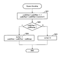
- FIG. 10 is a flowchart showing bypass decoding described in 9.2.3.2.3 IV of Non-Patent Document 1. Note that Patent Document 1 also describes a process similar to the process shown in the flowchart of FIG.
- FIG. 11 is a block diagram showing a configuration example of a general fixed binary arithmetic decoder (bypass) decoder 200 that performs bypass decoding, together with a debinarizer 110.
- the bypass decoder 200 shown in FIG. 11 is a 1-bin bypass decoder (one-bin bypass decoder) that inputs a bit stream via the switch 101 and switches the output destination of the bit stream and decodes the prefix one by one.
- a suffix bypass decoder (suffix-bin bypass decoder) 103 ⁇ ⁇ which inputs a bit stream via the switch 101 ⁇ and performs a decoding process of the suffix
- the 1-bin bypass decoder 102 performs the operation of codIOffset
- read_bits (1) ⁇ after performing the operation of codIOffset codIOffset ⁇ 1 for the codIOffset that is the offset in step S ⁇ b> 21. That is, the 1-bin bypass decoder 102 performs a logical OR operation with read_bits (1) after shifting codIOffset to the left by 1 bit. By the arithmetic processing in step S21, codIOffset is doubled and read_bits (1) is added. Note that codIOffset after the calculation process in step S21 is equivalent to the “offset” shown in FIGS. 8 and 9.
- the 1-bin bypass decoder 102 compares codIOffset with codIRange which is a range in step S22. When codIOffset is smaller than codIRange, the 1-bin bypass decoder 102 determines bin to be “0” (see step S23).
- the 1-bin bypass decoder 102 determines bin to be “1” (see step S24). In step S24 ⁇ ⁇ ⁇ ⁇ , the 1-bin bypass decoder 102 performs a codIOffset-codIRange normalization operation for decoding the next bin.
- the calculation in step S24 corresponds to the process of changing the offset starting point to the P point (see FIG. 9). Assuming that the bypass ⁇ ⁇ decoder is performing the decoding of b1 shown in FIG. 9B, the calculation in step S24 corresponds to a process of changing the offset starting point to the Q point (see FIG. 9B).
- the 1-bin bypass decoder 102 repeats bypass decoding of one bin from the bitstream until the terminal bin having a value of "0" is decoded.
- the suffix bypass decoder 103 ⁇ ⁇ decodes the suffix bin ⁇ ⁇ by the number of “1” (NumPrefixOnes) in the decoded prefix. Then, the debinarization unit 110 converts binary string into syntax data and outputs it.
- bypass decoder 200 can know NumSuffixBin before decoding the suffix. Accordingly, the bypass decoder 200 completes the decoding of the suffix only by performing the arithmetic operation of the binary arithmetic decoding range and offset comparison NumPrefixOnes times after prefetching NumPrefixOnes bits from the bitstream.
- offset update processing of NumPrefixOnes or less is also necessary.
- bypass decoder ⁇ ⁇ 200 cannot pre-read bit ⁇ ⁇ because it cannot obtain the number of bin ⁇ ⁇ constituting the prefix beforehand when decoding prefix. Therefore, according to bypass decoding ⁇ described in Non-Patent Document 1 and Patent Document 1, a binary arithmetic decoding range and offset comparison operation is always executed NumPrefixOnes times when a prefix is decoded. That is, the amount of computation when performing binary arithmetic decoding is large.
- An object of the present invention is to reduce the amount of calculation when performing binary arithmetic decoding.
- a video data binary arithmetic decoding apparatus is a video data binary arithmetic decoding apparatus that performs binary arithmetic decoding on a binary sequence prefixed with a continuous 1 and a terminal 0, and includes a range of binary arithmetic decoding, , A binary arithmetic decoding offset after N (N: natural number) bit look-ahead from the bitstream is compared, and a continuous one-number determining means is provided for determining the number of consecutive 1 in the binary sequence of N bits.
- a video data binary arithmetic decoding method is a video data binary arithmetic decoding method for performing binary arithmetic decoding on a binary string prefixed with a continuous 1 and a terminal 0 ⁇ ⁇ , and the binary arithmetic decoding range and The binary arithmetic decoding offset after prefetching N (N: natural number) bits from the bitstream is compared, and the number of consecutive 1 in the binary sequence of N bits is determined.
- a video data binary arithmetic decoding program is a video data binary arithmetic decoding program for performing binary arithmetic decoding on a binary string prefixed with a continuous 1 and a terminal 0.
- the arithmetic decoding range is compared with the binary arithmetic decoding offset after N bits (N: natural number) prefetched from the bitstream, and the process of determining the number of consecutive 1 s in the binary sequence of N bits is executed. It is characterized by that.
- the number of comparison operations between the range and the offset can be reduced, so that the amount of calculation when performing binary arithmetic decoding can be reduced.
- FIG. 1 (b) is a block diagram showing a configuration of an embodiment of a video decoding device according to the present invention.
- the video decoding device shown in FIG. 1B is a fixed binary arithmetic decoder (bypass decoder) 100 corresponding to an embodiment of the video data binary arithmetic decoding device, a debinarization unit 110, and transform decoding processing and predictive decoding processing. Including a predictive transform decoding unit 120.
- the video decoding apparatus may include an adaptive binary arithmetic decoder (not shown).
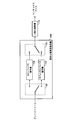
- Fig. 2 is a block diagram showing an example of the configuration of the bypass decoder 100.
- the bypass decoder 100 shown in Fig. 2 is a 1-bin bypass decoder (One-bin bypass decoder) that inputs a bit stream via the switch 101 and switches the output destination of the bit stream and decodes the prefix one by one.
- 1-bin bypass decoder One-bin bypass decoder
- a suffix bypass decoder (suffix-bin bypass ⁇ ⁇ decoder) 103 that inputs a bit stream via the switch 101 ⁇ and decodes the suffix
- a continuous 1 counter section that determines the number of consecutive “1” in the bitstream ( Successive-one Counter :: continuous one-number determining unit) 104, the output of the 1-bin bypass decoder 102, the suffix bin ⁇ output from the suffix bypass decoder 103, and the prefix bin ⁇ ⁇ output from the continuous 1-counter unit 104 Is provided with a switch 105 ⁇ ⁇ for selecting any of the above and outputting it to the binarization canceller 110.
- the continuous 1 counter unit 104 performs prefetching of the bitstream and determines the number of “1” cells constituting the prefix.
- the continuous 1 counter unit 104 ⁇ ⁇ ⁇ determines the number of “1” ⁇ constituting the prefix
- the prefix can also be decoded, so the 1-bin bypass decoder 102 ⁇ does not exist. May be.
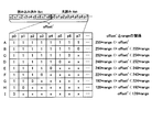
- FIG. 3 is an explanatory diagram showing an example of a process for determining the number of “1” cells constituting the prefix.
- the continuous 1 counter unit 104B has already read 9 bits (c0, c1, c2, c3, c4, c5, c6, c7, c8) from the bitstream, and further 8 bits (p0). , p1, p2, p3, p4, p5, p6, p7).
- a to I ⁇ outside the right column of the lower column are expedient codes for specifying elements when each row is regarded as an element.
- the 17-bit data (p7 is LSB (Least Significant Bit)) consisting of 9 bits that have been read and 8 bits that have been read-ahead are assumed to be offset '.
- a value obtained by multiplying the range (range) by (2 N -1) (N: the number of read-ahead bits) is defined as a weighted range.
- “x” represents “1” or “0”.
- the continuous 1 counter unit 104 ⁇ ⁇ ⁇ determines the number of “1” ⁇ constituting the prefix using the relationship illustrated in FIG. 3.
- the range of possible binary arithmetic decoding offsets is restricted as shown in Fig. 3, that is, N (N is a natural number) Note that even if bit prefetching is performed, the range that can be offset by binary arithmetic decoding is not N 2 +1 but N + 1. As can be seen from FIG. 3, as the number of consecutive “1” s increases, the upper limit of offset ′ increases according to the power of 2 (2 7 ⁇ m ) corresponding to the position m of “0”. .
- N times by comparing log 2 (N + 1) times by a method based on binary search without comparing N + 1 ranges as described in Non-Patent Document 1, N times, The number of consecutive “1” s in the binary string included in N bits can be determined.
- bypass decoder 100 pre-reads a predetermined N bits in prefix decoding, and compares the binary arithmetic decoding range and the offset after N bits pre-read (ie, offset ') log 2 (N + 1) times. Then, the number of consecutive “1” s in the binary string included in the N bits is determined. If the last "0" is not found in the prefetched N bits, the next N bits are prefetched until the last "0" is found and the number of consecutive "1” s is accumulated. That's fine.
- FIG. 4 ⁇ is a flowchart showing the determination process of NumPrefixOnes by the continuous 1 counter unit 104.
- peekNbits () represents a function for prefetching N bits from the bitstream.
- Step S2.1 The continuous 1 counter unit 104 determines whether offset ′ is less than (224 * range). Note that (224 * range) corresponds to the central element (specifically, the lower limit value of the central element) of the arrays A to I illustrated in FIG. However, in the example shown in FIG. 3B, since the number of elements is “9” ⁇ , it corresponds to the fourth element F from the bottom. If offset ′ is less than (224 * range), the process proceeds to step S2.1.1. If offset ′ is equal to or greater than (224 * range), the process proceeds to step S2.2.
- Step S2.2 The continuous 1 counter unit 104 determines whether or not offset ′ is less than (252 * range). If offset ′ is less than (252 * range), the process proceeds to step S2.2.1. If offset ′ is equal to or greater than (252 * range), the process proceeds to step S2.3. Note that (252 * range) corresponds to the center element between the element A ⁇ ⁇ and the element F ⁇ in the uppermost row in FIG.
- Step 2.3 (Step S2.3.1)
- the number of consecutive “1” tiles included in the prefetched 8 bits is determined by a maximum of 4 determinations.
- step S4 the continuous 1 counter unit 104 updates the offset according to the value of M. That is, when M is not 0 (corresponding to the case where there are one or more consecutive “1” bins), offset 1 is updated as follows (steps S41 and S42).
- offset ' offset'-((range ⁇ N)-(range ⁇ (NM)))
- the right side of the above expression corresponds to normalization of the offset (ie, subtraction of range) corresponding to the number of consecutive “1” bins. Further, the continuous 1 counter unit 104 updates the offset as follows based on the offset ′.
- offset offset '>> max (0, N-M-1) However, max (a, b) is a function that returns the larger value of inputs a and b.
- the continuous 1 counter unit 104 sets offset 'as offset (steps S41 and S43).
- step S5 the continuous 1 counter unit 104 updates NumPrefixOnes. That is, the continuous 1 counter unit 104 increments NumPrefixOnes by M.
- the number of binary arithmetic decoding range and offset comparison operations is log 2 (N + 1). That is, the number of comparison operations can be reduced N-log 2 (N + 1) times compared to the conventional technique.
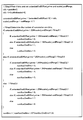
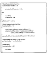
- FIG. 5A and FIG. 5B are explanatory diagrams showing pseudo code for realizing the above processing.
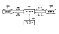
- FIG. 6 (b) is a block diagram showing a configuration example of an information processing system capable of realizing the function of the video decoding device according to the present invention.
- the information processing system illustrated in FIG. 6B includes a processor 1001, a program memory 1002, a storage medium 1003 for storing video data, and a storage medium 1004 for storing a bitstream.
- the storage medium 1003 and the storage medium 1004 may be separate storage media, or may be storage areas composed of the same storage medium.
- a magnetic storage medium such as a hard disk can be used as the storage medium.
- the program memory 1002 stores programs for realizing the functions of the blocks shown in FIG. 1B and FIG. Then, the processor 1001 implements the functions of the video decoding device shown in FIG. 1B and the bypass decoder 100 shown in FIG. 2B by executing processing according to the program stored in the program memory 1002.
Landscapes
- Engineering & Computer Science (AREA)
- Multimedia (AREA)
- Signal Processing (AREA)
- Theoretical Computer Science (AREA)
- Compression Or Coding Systems Of Tv Signals (AREA)
Description
(ステップS2.3.1)連続1カウンタ部104 は、offset' が(254*range) 未満であるか否か判断する。offset' が(254*range) 未満である場合、連続1カウンタ部104 は、M=6 とする(図3 における下欄の上から第3行参照)。そして、ステップS3 に移行する。offset' が(254*range) 以上である場合、ステップS2.3.2に移行する。なお、(254*range) は、図3 における要素A と要素C との間での中央の要素に対応する。
offset' =offset' -((range<<N) - (range<<(N-M)))
offset = offset' >>max(0, N - M - 1)
ただし、max(a,b)は入力a,bのうち大きなほうの値を返す関数である。
1) オフセット通常先読みビット数が7 ビットとし、プレフィックス用の先読みビット数を8 ビットとする。
2)変数定義:
extendedCodIOffset:7bit拡張済みオフセットすなわちoffset' (9 + 7 = 16 bits )
codIRange :レンジ
curBitNeeded:オフセット無効LSB ビット数 - 8、curBitNeeded=-8 は、16ビット全てが有効、curBitNeeded=-7 は、MSB 15ビットが有効、curBitNeeded=-1は、MSB 9ビットが有効
101 スイッチ
102 1ビンバイパス復号器(One-bin bypass decoder)
103 サフィックスバイパス復号器(suffix-bin bypass decoder )
104 連続1カウンタ部(連続1個数決定部)
105 スイッチ
110 2値化解除器
120 予測変換復号部
200 固定2値算術復号器(bypass decoder)
1001 プロセッサ
1002 プログラムメモリ
1003 記憶媒体
1004 記憶媒体
Claims (7)
- 連続する1 と終端の0 をプレフィックスとする2値列を2値算術復号する映像データ2値算術復号装置であって、
2値算術復号のレンジと、ビットストリームからN (N :自然数)ビット先読みした後の2値算術復号オフセットとを比較し、前記N ビットの2値列中に連続する1 の個数を決定する連続1個数決定手段を備える
ことを特徴とする映像データ2値算術復号装置。 - 連続1個数決定手段は、レンジとオフセットとを比較しながら2分探索により連続する1 の個数を決定する
請求項1記載の映像データ2値算術復号装置。 - 連続する1 と終端の0 をプレフィックスとする2値列を2値算術復号する映像復号装置であって、
請求項1又は請求項2記載の映像データ2値算術復号装置を備えることを特徴とする映像復号装置。 - 連続する1 と終端の0 をプレフィックスとする2値列を2値算術復号する映像データ2値算術復号方法であって、
2値算術復号のレンジと、ビットストリームからN (N :自然数)ビット先読みした後の2値算術復号オフセットとを比較し、前記N ビットの2値列中に連続する1 の個数を決定する
ことを特徴とする映像データ2値算術復号方法。 - レンジとオフセットとを比較しながら2分探索により連続する1 の個数を決定する請求項4記載の映像データ2値算術復号方法。
- 連続する1 と終端の0 をプレフィックスとする2値列を2値算術復号するための映像データ2値算術復号プログラムであって、
コンピュータに、
2値算術復号のレンジと、ビットストリームからN ビット(N :自然数)先読みした後の2値算術復号オフセットとを比較し、前記N ビットの2値列中に連続する1 の個数を決定する処理を実行させるための映像データ2値算術復号プログラム。 - コンピュータに、レンジとオフセットとを比較しながら2分探索により連続する1 の個数を決定する処理を実行させるための
請求項6記載の映像データ2値算術復号プログラム。
Priority Applications (2)
| Application Number | Priority Date | Filing Date | Title |
|---|---|---|---|
| JP2014531505A JPWO2014030347A1 (ja) | 2012-08-22 | 2013-08-21 | 映像データ2値算術復号装置および映像復号装置 |
| US14/422,217 US20150215633A1 (en) | 2012-08-22 | 2013-08-21 | Image-data binary arithmetic decoding device and image decoding device |
Applications Claiming Priority (2)
| Application Number | Priority Date | Filing Date | Title |
|---|---|---|---|
| JP2012183229 | 2012-08-22 | ||
| JP2012-183229 | 2012-08-22 |
Publications (1)
| Publication Number | Publication Date |
|---|---|
| WO2014030347A1 true WO2014030347A1 (ja) | 2014-02-27 |
Family
ID=50149673
Family Applications (1)
| Application Number | Title | Priority Date | Filing Date |
|---|---|---|---|
| PCT/JP2013/004941 Ceased WO2014030347A1 (ja) | 2012-08-22 | 2013-08-21 | 映像データ2値算術復号装置および映像復号装置 |
Country Status (3)
| Country | Link |
|---|---|
| US (1) | US20150215633A1 (ja) |
| JP (1) | JPWO2014030347A1 (ja) |
| WO (1) | WO2014030347A1 (ja) |
Families Citing this family (1)
| Publication number | Priority date | Publication date | Assignee | Title |
|---|---|---|---|---|
| WO2024091925A1 (en) * | 2022-10-25 | 2024-05-02 | Google Llc | Improved entropy bypass coding |
Citations (2)
| Publication number | Priority date | Publication date | Assignee | Title |
|---|---|---|---|---|
| JPH11163737A (ja) * | 1997-12-01 | 1999-06-18 | Hirobumi Nakamura | 情報源の符号化及び復号化の高速化装置 |
| JP2011501896A (ja) * | 2007-09-27 | 2011-01-13 | クゥアルコム・インコーポレイテッド | 最適cabac復号器 |
Family Cites Families (2)
| Publication number | Priority date | Publication date | Assignee | Title |
|---|---|---|---|---|
| CN1238787C (zh) * | 2003-10-17 | 2006-01-25 | 清华大学 | 嵌入式实时操作系统的二分查找式任务调度方法 |
| TWI343192B (en) * | 2009-06-12 | 2011-06-01 | Ind Tech Res Inst | Decoding method |
-
2013
- 2013-08-21 US US14/422,217 patent/US20150215633A1/en not_active Abandoned
- 2013-08-21 JP JP2014531505A patent/JPWO2014030347A1/ja active Pending
- 2013-08-21 WO PCT/JP2013/004941 patent/WO2014030347A1/ja not_active Ceased
Patent Citations (2)
| Publication number | Priority date | Publication date | Assignee | Title |
|---|---|---|---|---|
| JPH11163737A (ja) * | 1997-12-01 | 1999-06-18 | Hirobumi Nakamura | 情報源の符号化及び復号化の高速化装置 |
| JP2011501896A (ja) * | 2007-09-27 | 2011-01-13 | クゥアルコム・インコーポレイテッド | 最適cabac復号器 |
Also Published As
| Publication number | Publication date |
|---|---|
| JPWO2014030347A1 (ja) | 2016-07-28 |
| US20150215633A1 (en) | 2015-07-30 |
Similar Documents
| Publication | Publication Date | Title |
|---|---|---|
| CN107835431B (zh) | 对视频编码的方法和设备以及对视频解码的方法和设备 | |
| KR101826294B1 (ko) | 이미지들을 코딩 및 디코딩하는 방법, 코딩 및 디코딩 디바이스 및 그에 대응하는 컴퓨터 프로그램들 | |
| US8526750B2 (en) | Method and apparatus for encoding/decoding image by using adaptive binarization | |
| US20140205006A1 (en) | Super macro block based intra coding method and apparatus | |
| JP2016076963A (ja) | ビデオコーディングにおける並列コンテキスト計算 | |
| JP6036822B2 (ja) | 映像量子化パラメータ符号化方法、映像量子化パラメータ復号方法、装置およびプログラム | |
| US11234023B2 (en) | Features of range asymmetric number system encoding and decoding | |
| JPWO2008065822A1 (ja) | 符号化装置及び符号化方法 | |
| CN107105274B (zh) | 对视频量化参数解码的方法 | |
| CN108353174A (zh) | 并行算术译码技术 | |
| JP6149971B2 (ja) | 映像量子化パラメータ符号化方法及び映像量子化パラメータ復号方法 | |
| JP2022103284A (ja) | 映像符号化装置、映像復号装置、及びこれらのプログラム | |
| WO2014030347A1 (ja) | 映像データ2値算術復号装置および映像復号装置 | |
| AU2015252148B2 (en) | Image quantization parameter encoding method and image quantization parameter decoding method | |
| CN103702129A (zh) | 视频编码方法与视频编码装置 | |
| HK1232706A1 (en) | Image quantization parameter decoding method | |
| HK1234934A1 (en) | Image quantization parameter decoding method | |
| HK1232706A (en) | Image quantization parameter decoding method | |
| HK1234934A (en) | Image quantization parameter decoding method | |
| HK1194886B (en) | Method for coding video quantization parameter and method for decoding video quantization parameter | |
| HK1234936A (en) | Method for decoding video quantization parameter | |
| HK1194886A (en) | Method for coding video quantization parameter and method for decoding video quantization parameter | |
| HK1232707A (en) | Image quantization parameter encoding method and image quantization parameter decoding method | |
| HK1234935A1 (en) | Image quantization parameter decoding method | |
| HK1234936A1 (en) | Method for decoding video quantization parameter |
Legal Events
| Date | Code | Title | Description |
|---|---|---|---|
| 121 | Ep: the epo has been informed by wipo that ep was designated in this application |
Ref document number: 13831504 Country of ref document: EP Kind code of ref document: A1 |
|
| ENP | Entry into the national phase |
Ref document number: 2014531505 Country of ref document: JP Kind code of ref document: A |
|
| WWE | Wipo information: entry into national phase |
Ref document number: 14422217 Country of ref document: US |
|
| NENP | Non-entry into the national phase |
Ref country code: DE |
|
| 122 | Ep: pct application non-entry in european phase |
Ref document number: 13831504 Country of ref document: EP Kind code of ref document: A1 |