WO2014024273A1 - 動力駆動式カッター - Google Patents
動力駆動式カッター Download PDFInfo
- Publication number
- WO2014024273A1 WO2014024273A1 PCT/JP2012/070197 JP2012070197W WO2014024273A1 WO 2014024273 A1 WO2014024273 A1 WO 2014024273A1 JP 2012070197 W JP2012070197 W JP 2012070197W WO 2014024273 A1 WO2014024273 A1 WO 2014024273A1
- Authority
- WO
- WIPO (PCT)
- Prior art keywords
- actuator
- diameter
- gas
- rod
- power
- Prior art date
- Legal status (The legal status is an assumption and is not a legal conclusion. Google has not performed a legal analysis and makes no representation as to the accuracy of the status listed.)
- Ceased
Links
Images




Classifications
-
- A—HUMAN NECESSITIES
- A01—AGRICULTURE; FORESTRY; ANIMAL HUSBANDRY; HUNTING; TRAPPING; FISHING
- A01G—HORTICULTURE; CULTIVATION OF VEGETABLES, FLOWERS, RICE, FRUIT, VINES, HOPS OR SEAWEED; FORESTRY; WATERING
- A01G3/00—Cutting implements specially adapted for horticultural purposes; Delimbing standing trees
- A01G3/02—Secateurs; Flower or fruit shears
- A01G3/033—Secateurs; Flower or fruit shears having motor-driven blades
- A01G3/0335—Secateurs; Flower or fruit shears having motor-driven blades having elongated or extended handles
-
- A—HUMAN NECESSITIES
- A01—AGRICULTURE; FORESTRY; ANIMAL HUSBANDRY; HUNTING; TRAPPING; FISHING
- A01G—HORTICULTURE; CULTIVATION OF VEGETABLES, FLOWERS, RICE, FRUIT, VINES, HOPS OR SEAWEED; FORESTRY; WATERING
- A01G3/00—Cutting implements specially adapted for horticultural purposes; Delimbing standing trees
- A01G3/08—Other tools for pruning, branching or delimbing standing trees
- A01G3/081—Manual cutting tools not otherwise provided for, e.g. pruning hooks
Definitions
- the present invention relates to a power-driven cutter for easily cutting an object to be cut, such as a branching operation for cutting off a tree branch or an oil palm harvesting operation.
- the manual high branch cutting scissors that cut off the branches at the height of the tree are designed to reduce the burden of human power by using a boosting mechanism.
- a boosting mechanism there is a limit in manpower and the range of use is limited.
- a cutting tool is attached to the distal end of a rod-like elongated connecting member, an engine is attached to the proximal end of the connecting member, and the power generated by the engine is used.
- an engine is attached to the proximal end of the connecting member, and the power generated by the engine is used.
- the above working equipment for high places reduces the cutting resistance of the cutting tool by vibrating the cutting tool back and forth, but the shaft and leaves of the oil insulator are cut by the manpower of the worker. It requires labor and requires advanced cutting skills.
- the present invention has been conceived under such circumstances, and as a problem, the object to be cut can be easily obtained by using the combustion energy of LP gas filled in a commercially available cassette cylinder (LP gas cylinder). It is to enable cutting, to shorten the cutting time for cutting the object to be cut, to reduce the fuel cost of the engine, to simplify the structure, and to improve the reliability.
- LP gas cylinder cassette cylinder
- a power-driven cutter includes a combustion chamber that explosively burns fuel gas, an actuator that converts an expansion force of the combustion gas into kinetic energy in a linear direction, a cutting tool attached to an output rod of the actuator, and the combustion chamber Are provided with a fuel gas supply pump for supplying fuel gas and air at a constant ratio, and a reaction force canceling means for canceling the reaction force of the cutting tool.
- the reaction force canceling means includes a support rod attached to the body of the actuator and a reaction force receiving portion provided in an L shape at the front end of the support rod.
- the above-described reaction force receiving portion is provided with a cutter blade.
- the fuel gas supply pump comprises two pumps, a scavenging pump and a gas pump.
- the scavenging pump has a large diameter cylinder, a large diameter piston inscribed in the large diameter cylinder, and a large diameter piston mounted at the front end.
- a medium-diameter rod, a small-diameter piston inscribed in the medium-diameter rod and positioned at the rear end of the medium-diameter rod, and a front end are attached to the back surface of the front end plate of the scavenging pump, and a rear end is the small diameter
- a front end plate of the scavenging pump includes a gas inlet / outlet communicating with the air inlet / outlet and the small diameter rod, and the rear end plate includes the medium diameter lock. It has a through hole for sliding.
- a power-driven cutter has a combustion chamber that explosively burns fuel gas, an actuator that converts the expansion force of the combustion gas into kinetic energy in a linear direction, and a cutting tool that is mounted on the output rod of the actuator.
- an actuator is provided at the rear end portion of the combustion chamber, a relief valve is provided at the rear end portion of the actuator, a cylinder in which the relief valve is connected to the actuator, a piston provided in the cylinder, An exhaust port provided on a side surface of the actuator, a back pressure relief valve that is attached to the piston via a spring and opens and closes the exhaust port, and a bypass pipe that communicates the actuator and the cylinder. It is characterized by.
- the following effects can be obtained. That is, (1) Since the object to be cut can be cut with one blow, the cutting time can be shortened. (2) Since human power is not used for cutting the object to be cut, labor saving can be achieved. (3) Since human power is not used to cut the object to be cut, advanced skills are not required for harvesting. (4) The structure of the power driven cutter is simplified and the durability is increased. (5) The structure of the power-driven cutter is simplified and maintenance is easy. (6) The structure of the power driven cutter is simplified and the reliability is increased. (7) Since LP gas filled in a commercially available 250 g cassette cylinder (LP gas cylinder) is used as fuel, there are few harmful exhaust gases and the environmental load is small. (8) Low fuel costs and low maintenance costs. (9) Noise is lower than that of a conventional reciprocating internal combustion engine. (10) Lighter than conventional reciprocating internal combustion engines.
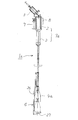
- FIG. 1 is a plan view showing an example of a power-driven cutter according to the present invention.
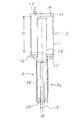
- FIG. 2 is a plan view including a partial cross section of the power take-out means.
- FIG. 3 is a plan view including a partial cross section showing a cutting reaction force canceling means.
- FIG. 4 is a cross-sectional view of a fuel gas-air supply pump that supplies fuel gas and air at a constant ratio.
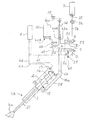
- FIG. 5 is a piping diagram of the power-driven cutter according to the present invention.
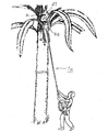
- FIG. 6 is an explanatory diagram of the cutting operation of the object to be cut.
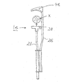
- FIG. 7 is a plan view showing another example of the power-driven cutter according to the present invention.
- FIG. 8 is a plan view showing another example of the power-driven cutter according to the present invention.
- FIG. 10 is a plan view showing another example of the power-driven cutter according to the present invention.
- a power-driven cutter 1a includes a combustion chamber (gas explosion chamber) 2, an actuator 3, a cutting tool 4a, a fuel gas-air supply pump 5, and a cutting reaction force canceling means 6, as shown in FIG. It is configured.
- the combustion chamber 2 and the actuator 3 constitute a power take-out means 9a for pressing.
- the combustion chamber 2 is provided with a cassette cylinder (LP gas cylinder) 7 and an ignition igniter 8 in its body.
- the combustion chamber 2 is a device that instantaneously explosively burns a mixed gas in which combustion gas (LP gas) and air are mixed at a constant rate, and as shown in FIG. And two end plates 12 and 13 that seal both front and rear ends thereof.
- LP gas combustion gas
- the front end plate 12 has an operating piston 14 of the actuator 3 inserted into a through-hole provided in the center thereof, and has a combustion gas discharge port 15 at a position away from the center.
- the rear end plate 13 includes a mixed gas supply port 16 and an ignition plug 17.
- the actuator 3 is a device that converts the expansion force of combustion gas into linear kinetic energy.
- the actuator 3 is a cylinder-like member mounted on the operating piston 14 and the front end plate 12 of the combustion chamber 2. It is comprised from the trunk
- the front end portion of the body portion 18 is closed by the end plate 20, but the front end portion of the output rod 19 protrudes from a through hole provided in the end plate 20.
- Reference numeral S ⁇ b> 1 indicates the stroke of the working piston 14.
- the output rod 19 is connected to a cutting force transmission rod 21 having a predetermined length at its front end portion, and a cutting tool (cutting blade) 4 a is attached to the front end portion of the cutting force transmission rod 21.
- the cutting tool 4a has a spatula-shaped blade body 24a having a wider width at the front end portion than at the root portion, and the front end portion is a sharp cutting edge 25 suitable for cutting the cutting object X. ing. Further, the front end portion of the output rod 19 and the cutting force transmission rod 21 are accommodated in the outer cylinder 22.
- the fuel gas-air supply pump 5 is a device that supplies fuel gas and air to the combustion chamber 2 and includes a scavenging pump 31 and a gas pump 32 as shown in FIG.
- the scavenging pump 31 has a large-diameter cylinder 33, a large-diameter piston 34 inscribed in the large-diameter cylinder 33, a hollow medium-diameter rod 35 with the large-diameter piston 34 attached to the front end, and both front and rear ends of the large-diameter cylinder 33.
- a handle 39 is attached to a sealing member 38 that is composed of end plates 36 and 37 that are attached to the rear end of the medium diameter rod 35.
- the gas pump 32 is a pump having the medium diameter rod 35 as a cylinder, and a small diameter piston 40 is disposed in the medium diameter rod 35 at a position in contact with the medium diameter rod 35 and close to the sealing member 38. ing.
- the front end plate 36 includes a gas inlet / outlet 43 communicating with the air inlet / outlet 42 and the small-diameter rod 41. Further, the rear end plate 37 has a through hole for sliding the medium diameter rod 35.
- Reference numeral S ⁇ b> 2 indicates the stroke of the handle 39 or the large-diameter piston 34.
- the cutting reaction force canceling means 6 is a device that cancels the cutting reaction force of the cutting tool 4a, and as shown in FIG. 3, a rod-like support attached to the side surface of the outer cylinder 22 covering the cutting force transmission rod 21. It comprises a member 26 and a reaction force receiving portion 27 attached to the front end of the support member 26 in an L shape.
- FIG. 5 is a piping system diagram of a power-driven cutter according to the present invention, and the power-driven cutter 1 a includes a gas switching valve 51 and an exhaust gas switching valve 52. These switching valves 51 and 52 are simultaneously operated by a common manual handle 53.
- the gas switching valve 51 is a 2-port 2-position switching valve, and the A port is connected to the opening / closing valve 55 of the 250-g cassette cylinder 7 via the gas pipe 54.
- the gas pipe 54 includes a pressure reducing valve 56 at an intermediate portion thereof.
- the B port of the gas switching valve 51 communicates with the check valve 43 a at the gas inlet of the gas pump 32 via the gas pipe 57.
- the exhaust gas switching valve 52 is a 2-port 2-position switching valve, and the C port is connected to the combustion gas discharge port 15 of the combustion chamber 2 via the combustion gas discharge pipe 58.
- the D port of the exhaust gas switching valve 52 is connected to the exhaust gas discharge pipe 59.
- the ignition switch 60 provided in the vicinity of the exhaust gas switching valve 52 is electrically connected to the ignition igniter 8 via the wiring 61.
- the ignition igniter 8 is connected to the ignition plug 17 through one wiring 62 and connected to the combustion chamber 2 through the other wiring 63.
- the check valve 42 a at the air outlet of the scavenging pump 31 communicates with the check valve 16 a at the mixed gas supply port of the combustion chamber 2 via the gas pipe 64.
- the gas pipe 64 includes a gas mixer 65 at an intermediate portion thereof.
- check valve 43 b at the gas outlet of the gas pump 32 is connected to the gas pipe 64 on the upstream side of the gas mixer 65 through the gas pipe 66.
- reference numeral 42b denotes an air inlet check valve.
- the switch valve handle 53 shown in FIG. 5 When harvesting oil palm, the switch valve handle 53 shown in FIG. 5 is pushed to connect the A port and the B port of the gas switch valve 51, and the C port and D port of the exhaust gas switch valve 52 are connected. By this operation, the residual gas in the combustion chamber 2 is discharged into the atmosphere, and the operating piston 14 of the actuator 3 is moved back into the combustion chamber 2 by its own weight as indicated by a solid line.
- the L-shaped reaction force receiving portion 27 is inserted behind the shaft of the oil insulator x that is the object to be cut (n1).
- the handle 39 of the pump 5 is pulled to introduce fuel LP gas into the gas pump 32, and at the same time, air is introduced into the scavenging pump 31, and the capacity of both is measured (n2).
- the handle 39 of the pump 5 is pushed to supply the LP gas in the gas pump 32 and the air in the scavenging pump 31 to the combustion chamber 2 through the gas supply pipe 64 (n3).
- the LP gas and air are mixed while passing through the gas supply pipe 64, but are further uniformly mixed due to the presence of the gas mixer 65.
- reaction force resulting from the explosive combustion of the mixed gas is offset by the reaction force receiving portion 27.
- the oil palm is harvested by repeating the steps (n1) to (n4).
- the palm leaves are also cut and removed as appropriate.
- the selector valve handle 53 is pulled back to the initial position.
- a cutter blade is attached to the reaction force receiving portion 27 and the reaction force is used as cutting energy.
- the power can be reduced, the cylinder size can be reduced, and the weight can be reduced.
- the power-driven cutter 1 b has a push rod 28 mounted in a T shape on the front end of the cutting force transmission rod 21, and a sickle-shaped cutting tool 4 b on the front end of the support member 26. It is attached to the shape.
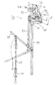
- the power-driven cutter 1 c forms a power take-out means 9 c for cutting by providing an actuator 3 at the rear end of the combustion chamber 2.
- the output rod 19 which is one of the components of the actuator 3 passes through the combustion chamber 2 and is provided with a hook-shaped cutting tool 4c at the front end thereof.
- the blade 24c of the hook-shaped cutting tool 4c has a sharp cutting edge 25 on the output rod 19 side.
- the combustion chamber 2 includes a gas supply port 16 and an ignition plug 17 at the center of the trunk.
- the gas supply port 16 is connected to the opening / closing valve 55 of the cassette cylinder 7 via a gas supply pipe 71, and the ignition plug 17 is connected to an ignition device 68 via a wiring 67.
- the on-off valve 55 and the ignition device 68 of the cassette cylinder 7 are operated by a trigger 72.
- the combustion chamber 2 is provided with an exhaust piston 73 having an exhaust check valve therein.
- the exhaust piston 73 is disposed so as to be positioned at the front end portion of the combustion chamber 2 when the operating piston 14 of the actuator is positioned at the front end portion of the cylindrical body 18 of the actuator.
- the actuator 3 is provided with a relief valve 74 at its rear end.
- the relief valve 74 includes a cylinder 75 connected to the cylindrical body 18 of the actuator 3, a piston 76 provided in the cylinder 75, an exhaust port 77 provided on the side of the actuator 3, and the piston 76 via a spring. And a pressure relief valve 78 that opens and closes the exhaust port 77, a bypass pipe 79 that communicates the actuator 3 and the cylinder 75, and a trigger 80 that operates the relief valve 74.
- combustion chamber 2 is provided with an exhaust valve 69 and a trigger 81 for operating the exhaust valve 69 at the front end thereof, and an outside air intake valve 82 at the rear end thereof.
- the trigger 72 for operating the opening / closing valve 55 and the ignition device 68 of the cassette cylinder 7, the trigger 80 for operating the relief valve 74, and the trigger 81 for operating the exhaust valve 69 are interlocked by the operation cord 70.
- FIG. 8 also serves as a diagram showing the gas filling and ignition process.
- the combustion gas supplied into the combustion chamber 2 is instantaneously explosively burned by ignition, as shown in the explosion process of FIG. 9A.
- the operating piston 14 moves backward in the direction of the rear end portion of the actuator 3, and the cutting object (not shown) is instantaneously cut by the pulling operation of the cutting tool 4c.
- the gas in the actuator 3 is released into the atmosphere from an exhaust port 77 provided in the actuator 3.
- the cutting tool 4 d includes a fixed blade 91 and a movable blade 92.
- the fixed blade 91 is fixed to a support member 94 mounted on the upper end portion of the support bar 93 so as to protrude obliquely upward, and the movable blade 92 is rotatable to the support member 94 by two long and short rings 95 and 6. It is attached.
- the short ring 96 has one end pivotally attached to the support member 94 and the other end pivotally attached to the central portion of the movable blade 92.
- the center part of the long ring 95 is pivotally attached to the support member 94.
- one end thereof is pivotally attached to the rear end portion of the movable blade 92, and the upper end of the connecting rod 97 is pivotally attached to the other end.
- symbol ⁇ indicates the rotation angle of the short ring 96
- ⁇ indicates the rotation angle of the long ring 95.
- the support bar 93 is provided with a lever 98 in the middle thereof.
- the lever 98 is pivotally attached to the lower end of the connecting rod 97.
- the lever 98 has a cutting force transmitting rod 21 pivotally attached to the end thereof.
- Reference numeral 14 denotes an operating piston provided on the power transmission rod 21, and this operating piston 14 is an actuator provided at the rear end of a combustion chamber (not shown), like the operating piston 14 of the third embodiment. (Not shown).
Landscapes
- Life Sciences & Earth Sciences (AREA)
- Biodiversity & Conservation Biology (AREA)
- Ecology (AREA)
- Forests & Forestry (AREA)
- Environmental Sciences (AREA)
- Harvesting Machines For Specific Crops (AREA)
- Portable Nailing Machines And Staplers (AREA)
Description
本発明は、樹木の枝を切り落とす枝落とし作業、或いは、油椰子(oil palm)の収穫作業など、切断対象物の切断を容易に行なうための動力駆動式カッターに関するものである。
樹木の高所にある枝を切り落とす手動式の高枝切りバサミは、倍力機構などによって人力の負担軽減を図っているが、マンパワーでは限界があり、使用範囲が限定される。
他方、油椰子を収穫する装置として、ロッド状の細長い連結部材の先端部に切断作業用工具を取り付けるとともに、前記連結部材の基端部にエンジンを取り付け、このエンジンによって発生させた動力を利用して前記切断作業用工具を前後に振動させるようにした高所用作業機が提案されている(例えば、特許文献1参照。)。
上記高所用作業機は、切断作業用工具を前後に振動させることにより、切断作業用工具の切断抵抗を軽減しているが、油椰子の軸や葉の切断は、作業員のマンパワーで行っており、労力が要り、高度な切断スキルが必要となる。
また、上記高所用作業機は、エンジン(往復動内燃機関)を使用しているため、高所用作業機の重量が嵩み、作業員の負担が大きい。更に、切断作業用工具を前後に振動させる手段として、クランクやエンジンを使用しているため振動や騒音が大きい。
本発明は、このような事情によって考え出されたものであって、課題としては、市販のカセットボンベ(LPガスボンベ)に充填されているLPガスの燃焼エネルギーを利用して切断対象物を容易に切断できるようにすること、切断対象物を切断する切断時間の短縮を図ること、エンジンの燃料費の削減を図ること、構造をシンプルにし、信頼性の向上を図ることにある。
本発明の動力駆動式カッターは、燃料ガスを爆発的に燃焼させる燃焼室、燃焼ガスの膨張力を直線方向の運動エネルギーに変換するアクチュエータ、該アクチュエータの出力ロッドに装着した切断工具、前記燃焼室に燃料ガスと空気を一定の割合で供給する燃料ガス供給ポンプ、および前記切断工具の反力を相殺する反力相殺手段を具備することを特徴としている。
前記反力相殺手段は、アクチュエータの胴部に取り付けた支持棒と、該支持棒の前端部にL形状に設けた反力受け部より構成されていることを特徴としている。
前記反力受け部にカッタ刃を設けたことを特徴としている。
また、前記燃料ガス供給ポンプは、掃気ポンプとガスポンプの2つのポンプから成り、前記掃気ポンプは、大径シリンダ、該大径シリンダに内接する大径ピストン、該大径ピストンを前端部に装着した中空状の中径ロッド、前記大径シリンダの前後両端を密閉する端板、前記中径ロッドの後端部に装着した密閉部材、及び前記密閉部材に装着したハンドルより成り、前記ガスポンプは、前記中径ロッド、該中径ロッドに内接すると共に前記中径ロッドの後端部に位置する小径ピストン、及び前端部が前記掃気ポンプの前部端板の背面に装着され、後端部が前記小径ピストンを貫通する中空状の小径ロッドから成り、前記掃気ポンプの前部端板は、空気出入口及び前記小径ロッドに連通するガス出入口を備え、前記後部端板は、前記中径ロッドを摺動するための貫通孔を有している。
本発明の動力駆動式カッターは、燃料ガスを爆発的に燃焼させる燃焼室、燃焼ガスの膨張力を直線方向の運動エネルギーに変換するアクチュエータ、及び前記アクチュエータの出力ロッドに装着した切断工具を有する動力駆動式カッターにおいて、前記燃焼室の後端部にアクチュエータを設けると共に、該アクチュエータの後端部にリリーフ弁を設け、該リリーフ弁がアクチュエータに接続しているシリンダー、該シリンダー内に設けたピストン、前記アクチュエータの側面に設けた排気口、前記ピストンにスプリングを介して取り付けられ、かつ、前記排気口を開閉する背圧リリーフ弁、前記アクチュエータ及び前記シリンダーを連通するバイパス管より構成構成されていることを特徴としている。
本発明によれば、次のような効果が得られる。すなわち、
(1)切断対象物を一撃で切断できるため、切断時間の短縮が図れる。
(2)切断対象物の切断に人力を使用しないため、省力化が図れる。
(3)切断対象物の切断に人力を使用しないため、収穫に高度なスキルが不要。
(4)動力駆動式カッターの構造がシンプルになり、耐久性が増す。
(5)動力駆動式カッターの構造がシンプルになり、メンテナンスが容易。
(6)動力駆動式カッターの構造がシンプルになり、信頼性が増す。
(7)燃料として、市販の250gのカセットボンベ(LPガスボンベ)に充填されているLPガスを使用するため、有害な排ガスが少なく、環境負荷が小さい。
(8)燃料費が安価で、維持費が少ない。
(9)従来の往復動内燃機関よりも騒音が低い。
(10)従来の往復動内燃機関よりも軽量。
(1)切断対象物を一撃で切断できるため、切断時間の短縮が図れる。
(2)切断対象物の切断に人力を使用しないため、省力化が図れる。
(3)切断対象物の切断に人力を使用しないため、収穫に高度なスキルが不要。
(4)動力駆動式カッターの構造がシンプルになり、耐久性が増す。
(5)動力駆動式カッターの構造がシンプルになり、メンテナンスが容易。
(6)動力駆動式カッターの構造がシンプルになり、信頼性が増す。
(7)燃料として、市販の250gのカセットボンベ(LPガスボンベ)に充填されているLPガスを使用するため、有害な排ガスが少なく、環境負荷が小さい。
(8)燃料費が安価で、維持費が少ない。
(9)従来の往復動内燃機関よりも騒音が低い。
(10)従来の往復動内燃機関よりも軽量。
2 燃焼室
3 アクチュエータ
4a 切断工具
5 燃料ガス供給ポンプ
6 反力相殺手段
19 出力ロッド
3 アクチュエータ
4a 切断工具
5 燃料ガス供給ポンプ
6 反力相殺手段
19 出力ロッド
本発明に係る動力駆動式カッター1aは、図1に示すように、燃焼室(ガス爆発室)2、アクチュエータ3、切断工具4a、燃料ガス-空気供給ポンプ5、及び切断反力相殺手段6より構成されている。
上記燃焼室2及びアクチュエータ3は、押切用の動力取り出し手段9aを構成している。また、燃焼室2は、その胴部にカセットボンベ(LPガスボンベ)7及び着火用イグナイター8を備えている。
上記燃焼室2は、燃焼ガス(LPガス)と空気が一定の割合で混合している混合ガスを瞬時に爆発的に燃焼させる機器であり、図2に示すように、シリンダー状の胴部11と、その前後両端を密閉している2つの端板12,13より構成されている。
前部端板12は、その中心部に設けた貫通孔にアクチュエータ3の作動ピストン14を挿入し、前記中心部から外れた箇所に燃焼ガス排出口15を備えている。他方、後部端板13は、混合ガス供給口16及び着火プラグ17を備えている。
上記アクチュエータ3は、燃焼ガスの膨張力を直線方向の運動エネルギーに変換する機器であり、図2に示すように、前記作動ピストン14、燃焼室2の前部端板12に装着したシリンダ状の胴部18、及び前記作動ピストン14の前端部に設けた出力ロッド19より構成されている。胴部18の前端部は、端板20によって塞がれているが、端板20に設けた貫通孔から出力ロッド19の前端部が突出している。符号S1は、作動ピストン14のストロークを示している。
上記出力ロッド19は、図3に示すように、その前端部に所定長の切断力伝達ロッド21を接続すると共に、当該切断力伝達ロッド21の前端部に切断工具(切断刃物)4aを装着している。切断工具4aは、根元部よりも前端部の方が横幅が広くなっているへら形の刃体24aを有し、当該前端部は、切断対象物Xの切断に適した鋭利な刃先25となっている。また、出力ロッド19の前端部分及び切断力伝達ロッド21は、外筒22内に収容されている。
上記燃料ガス-空気供給ポンプ5は、燃焼室2に燃料ガスと空気を計量供給する機器であり、図4に示すように、掃気ポンプ31及びガスポンプ32から構成されている。
掃気ポンプ31は、大径シリンダ33、大径シリンダ33に内接する大径ピストン34、大径ピストン34を前端部に装着した中空状の中径ロッド35、および大径シリンダ33の前後両端を密閉する端板36,37より構成され、中径ロッド35の後端部に装着した密閉部材38にハンドル39を取り付けている。
ガスポンプ32は、前記中径ロッド35をシリンダとするポンプであり、前記中径ロッド35内に、当該中径ロッド35に内接すると共に、前記密閉部材38に近接する位置に小径ピストン40を配している。前記前部端板36の背面中央に装着させた中空状の小径ロッド41は、前記小径ピストン40を貫通すると共に、当該小径ピストン40に固定されている。
前記前部端板36は、空気出入口42及び小径ロッド41に連通するガス出入口43を備えている。また、後部端板37は、中径ロッド35を摺動するための貫通孔を有している。符号S2は、ハンドル39、或いは大径ピストン34のストロークを示している。
切断反力相殺手段6は、切断工具4aの切断反力を相殺する機器であり、図3に示すように、前記切断力伝達ロッド21を覆っている外筒22の側面に取り付けた棒状の支持部材26と、この支持部材26の前端部にL字状に取り付けた反力受け部27より構成されている。
図5は、本発明に係る動力駆動式カッターの配管系統図であり、動力駆動式カッター1aは、ガス切替弁51及び排ガス切替弁52を備えている。これらの切替弁51,52は、共通の手動ハンドル53によって同時に操作される。
上記ガス切替弁51は、2ポート2位置切替弁であり、Aポートは、ガス管54を介して250gのカセットボンベ7の開閉弁55に接続している。このガス管54は、その中間部に減圧弁56を備えている。他方、ガス切替弁51のBポートは、ガス管57を介してガスポンプ32のガス導入口の逆止弁43aに連通している。
上記排ガス切替弁52は、2ポート2位置切替弁であり、Cポートは、燃焼ガス排出管58を介して燃焼室2の燃焼ガス排出口15に接続している。他方、排ガス切替弁52のDポートは、排ガス放出管59に接続している。
排ガス切替弁52の近傍に設けられた着火スイッチ60は、配線61を介して着火用イグナイター8と電気的に接続している。また、この着火用イグナイター8は、一方の配線62を介して着火プラグ17に接続し、他方の配線63を介して燃焼室2に接続している。
掃気ポンプ31の空気送出口の逆止弁42aは、ガス管64を介して燃焼室2の混合ガス供給口の逆止弁16aに連通している。このガス管64は、その中間部にガスミキサ65を備えている。
また、上記ガスポンプ32のガス送出口の逆止弁43bは、ガス管66を介してガスミキサ65の上流側において前記ガス管64に接続している。図中、符号42bは、空気導入口の逆止弁である。
油椰子を収穫する場合は、図5に示す切替弁のハンドル53を押してガス切替弁51のAポートとBポートを連通させるとともに、排ガス切替弁52のCポートとDポートを連通させる。この操作によって燃焼室2内の残存ガスが大気中に排出され、自重によってアクチュエーター3の作動ピストン14が実線で示すように燃焼室2内に後退する。
次に、図6に示すように、動力駆動式カッター1aを両手で持ちながらL字状の反力受け部27を切断対象物である油椰子xの軸の背後に差し込む(n1)。
次に、前記ポンプ5のハンドル39を引いてガスポンプ32内に燃料のLPガスを導入すると同時に、掃気ポンプ31内に空気を導入し、両者の容量を計量する(n2)。
次に、前記ポンプ5のハンドル39を押してガスポンプ32内のLPガス及び掃気ポンプ31内の空気をガス供給パイプ64を通って燃焼室2に供給する(n3)。LPガス及び空気は、ガス供給パイプ64を通過する間に混合するが、ガスミキサ65の存在により、更に、均一に混合される。
次に、着火スイッチ60を操作して着火プラグ17を点火すると、LPガスと空気が混合した混合ガスが瞬時に爆発的に燃焼してアクチュエーター3の作動ピストン14が前方に押し出される。そして、図3に示すように、切断力伝達ロッド21の前端に取り付けた切断工具4aが前方に押し出され、切断対象物である油椰子xの軸が瞬時に切断される(n4)。
上記混合ガスの爆発的な燃焼に起因する反力は、反力受け部27によって相殺される。
以下、(n1)乃至(n4)の工程を繰り返して油椰子を収穫する。
その際、椰子の葉も適宜切断して除去する。収穫作業終了後、切替弁のハンドル53を引いて初期位置に戻す。
なお、上記反力受部27にカッタ刃を取り付け、反動力を切断エネルギーとして利用する。これにより、動力を削減し、シリンダーサイズを小さくし、軽量化が図れる。
以下、その他の実施形態について説明する。なお、第1実施形態の部材と同じ部材には、同じ符号を付けて詳しい説明を省略している。
先ず、本発明の第2実施形態について説明する。動力駆動式カッター1bは、図7のように、切断力伝達用ロッド21の前端部に押し棒28をT字状に装着し、支持部材26の前端部に鎌型の切断工具4bをL字状に装着している。
次に、本発明の第3実施形態について説明する。動力駆動式カッター1cは、図8のように、燃焼室2の後端部にアクチュエータ3を設けることにより、引き切り用の動力取り出し手段9cを構成している。
アクチュエータ3の構成部品の一つである出力ロッド19は、燃焼室2を貫通し、その前端部にフック状の切断工具4cを設けている。このフック状の切断工具4cの刃体24cは、出力ロッド19側が鋭利な刃先25になっている。
上記燃焼室2は、胴部中央にガス供給口16及び着火プラグ17を備えている。ガス供給口16は、ガス供給管71を介してカセットボンベ7の開閉弁55に接続し、着火プラグ17は、配線67を介して着火装置68に接続している。カセットボンベ7の開閉弁55及び着火装置68は、トリガー72によって操作するようになっている。
上記燃焼室2は、その内部に排気逆止弁を具備する排気ピストン73を設けている。この排気ピストン73は、アクチュエータの作動ピストン14がアクチュエータのシリンダー状の胴部18の前端部に位置するとき、燃焼室2の前端部に位置するように配置されている。
上記アクチュエータ3は、その後端部にリリーフ弁74を設けている。このリリーフ弁74は、アクチュエータ3のシリンダー状の胴部18に接続しているシリンダー75、シリンダー75内に設けたピストン76、アクチュエータ3の側面に設けた排気口77、前記ピストン76にスプリングを介して取り付けられ、かつ、前記排気口77を開閉する排圧リリーフ弁78、前記アクチュエータ3とシリンダー75とを連通するバイパス管79、及びリリーフ弁74を操作するトリガー80より構成されている。
また、燃焼室2は、その前端部に排気弁69及び当該排気弁69を操作するトリガー81を設け、その後端部に外気吸気弁82を設けている。
上記カセットボンベ7の開閉弁55や着火装置68を操作するトリガー72、リリーフ弁74を操作するトリガー80、及び排気弁69を操作するトリガー81は、操作索70によって連動するようになっている。
ここで、図8は、ガス充填及び着火工程を示す図も兼ねており、燃焼室2内に供給された燃焼ガスが着火によって瞬時に爆発的に燃焼すると、図9Aの爆発工程に示すように、作動ピストン14がアクチュエータ3の後端部の方向に後退し、切断工具4cの引き動作によって切断対象物(図示せず)が瞬時に切断される。この時、アクチュエータ3内のガスがアクチュエータ3に設けた排気口77から大気中に放出される。
図9Bに示すように、作動ピストン14がアクチュエータ3の後端部(ストローク端)に到達すると、アクチュエータ3内の高圧燃焼ガスがバイパス管79を通ってリリーフ弁74のシリンダー75内に導入され、アクチュエータ3の側面に設けた排気口77が排圧リリーフ弁78によって密閉される。
次に、図9Cの戻り及び排ガス置換工程に示すように、リリーフ弁74のトリガー80を燃焼室2側に倒すと、燃焼室2の前端部に設けたトリガー81によって燃焼室2の前端部に設けられている排気弁69が開放され、燃焼室2内の燃焼ガスが大気中に排出される。これと同時に、アクチュエータ3の後端部に設けられているリリーフ弁74内の燃焼ガスがバイパス管79を経てアクチュエーター3に逆流する。そして、図9Dに示すように、アクチュエータ3の作動ピストン14が初期位置に復帰する(スタンバイ工程)。
次に、本発明の第4実施形態について説明する。動力駆動式カッター1dは、図10に示すように、切断工具4dが固定刃91及び可動刃92から構成されている。
固定刃91は、支持棒93の上端部に装着した支持部材94に斜め上方に突出するように固定され、可動刃92は、長短2つのリング95,6によって前記支持部材94に回動自在に取り付けられている。
短尺リング96は、一端が前記支持部材94に軸着され、他端が可動刃92の中央部に軸着されている。他方、長尺リング95は、その中央部が前記支持部材94に軸着されている。更に、その一端が可動刃92の後端部に軸着され、他端に連結棒97の上端が軸着されている。ここで、符号αは短尺リング96の回動角度、βは長尺リング95の回動角度を示している。
前記支持棒93は、その中間部にレバー98を設けている。このレバー98は、前記連結棒97の下端を軸着している。
また、前記レバー98は、その端部に切断力伝達用ロッド21を軸着している。符号14は、動力伝達用ロッド21に設けた作動ピストンであり、この作動ピストン14は、第3実施形態の作動ピストン14と同様に、燃焼室(図示せず)の後端部に設けたアクチュエータ(図示せず)内に位置している。
Claims (5)
- 燃料ガスを爆発的に燃焼させる燃焼室、燃焼ガスの膨張力を直線方向の運動エネルギーに変換するアクチュエータ、該アクチュエータの出力ロッドに装着した切断工具、前記燃焼室に燃料ガスと空気を一定の割合で供給する燃料ガス供給ポンプ、および前記切断工具の反力を相殺する反力相殺手段を具備することを特徴とする動力駆動式カッター。
- 前記反力相殺手段を、アクチュエータの胴部に取り付けた支持棒と、該支持棒の前端部にL形状に設けた反力受け部より構成したことを特徴とする請求項1記載の動力駆動式カッター。
- 前記反力受け部にカッタ刃を設けたことを特徴とする請求項2記載の動力駆動式カッター。
- 前記燃料ガス供給ポンプは、掃気ポンプとガスポンプの2つのポンプから成り、
前記掃気ポンプは、大径シリンダ、該大径シリンダに内接する大径ピストン、該大径ピストンを前端部に装着した中空状の中径ロッド、前記大径シリンダの前後両端を密閉する端板、前記中径ロッドの後端部に装着した密閉部材、及び前記密閉部材に装着したハンドルより成り、
前記ガスポンプは、前記中径ロッド、該中径ロッドに内接すると共に前記中径ロッドの後端部に位置する小径ピストン、及び前端部が前記掃気ポンプの前部端板の背面に装着され、後端部が前記小径ピストンを貫通する中空状の小径ロッドから成り、
前記掃気ポンプの前部端板は、空気出入口及び前記小径ロッドに連通するガス出入口を備え、前記後部端板は、前記中径ロッドを挿入するための貫通孔を有することを特徴とする請求項1記載の動力駆動式カッター。 - 燃料ガスを爆発的に燃焼させる燃焼室、燃焼ガスの膨張力を直線方向の運動エネルギーに変換するアクチュエータ、及び前記アクチュエータの出力ロッドに装着した切断工具を有する動力駆動式カッターにおいて、前記燃焼室の後端部にアクチュエータを設けると共に、該アクチュエータの後端部にリリーフ弁を設け、該リリーフ弁がアクチュエータに接続しているシリンダー、該シリンダー内に設けたピストン、前記アクチュエータの側面に設けた排気口、前記ピストンにスプリングを介して取り付けられ、かつ、前記排気口を開閉する背圧リリーフ弁、前記アクチュエータ及び前記シリンダーを連通するバイパス管より構成構成されていることを特徴とする動力駆動式カッター。
Priority Applications (2)
| Application Number | Priority Date | Filing Date | Title |
|---|---|---|---|
| PCT/JP2012/070197 WO2014024273A1 (ja) | 2012-08-08 | 2012-08-08 | 動力駆動式カッター |
| JP2012555626A JP5237508B1 (ja) | 2012-08-08 | 2012-08-08 | 動力駆動式カッター |
Applications Claiming Priority (1)
| Application Number | Priority Date | Filing Date | Title |
|---|---|---|---|
| PCT/JP2012/070197 WO2014024273A1 (ja) | 2012-08-08 | 2012-08-08 | 動力駆動式カッター |
Publications (1)
| Publication Number | Publication Date |
|---|---|
| WO2014024273A1 true WO2014024273A1 (ja) | 2014-02-13 |
Family
ID=49041737
Family Applications (1)
| Application Number | Title | Priority Date | Filing Date |
|---|---|---|---|
| PCT/JP2012/070197 Ceased WO2014024273A1 (ja) | 2012-08-08 | 2012-08-08 | 動力駆動式カッター |
Country Status (2)
| Country | Link |
|---|---|
| JP (1) | JP5237508B1 (ja) |
| WO (1) | WO2014024273A1 (ja) |
Cited By (1)
| Publication number | Priority date | Publication date | Assignee | Title |
|---|---|---|---|---|
| CN110521386A (zh) * | 2019-07-15 | 2019-12-03 | 山东省农业机械科学研究院 | 单枝核果采收臂 |
Families Citing this family (3)
| Publication number | Priority date | Publication date | Assignee | Title |
|---|---|---|---|---|
| CN103650938B (zh) * | 2013-12-02 | 2015-09-09 | 宁波利豪机械有限公司 | 一种气动弹簧式棕榈树切割机 |
| CN108617318A (zh) * | 2018-05-11 | 2018-10-09 | 桐城市天地泰农业科技有限公司 | 一种快速树枝修剪装置 |
| CN108617252B (zh) * | 2018-05-14 | 2020-12-22 | 道真自治县银会花椒种植有限公司 | 一种花椒采收装置 |
Citations (4)
| Publication number | Priority date | Publication date | Assignee | Title |
|---|---|---|---|---|
| JPS4859651U (ja) * | 1971-11-14 | 1973-07-28 | ||
| JPS536857U (ja) * | 1976-07-06 | 1978-01-21 | ||
| JPS54123361U (ja) * | 1978-02-18 | 1979-08-29 | ||
| JPS61257116A (ja) * | 1985-05-10 | 1986-11-14 | カ−ツ株式会社 | ヤシ科植物における収穫の方法及び装置 |
-
2012
- 2012-08-08 JP JP2012555626A patent/JP5237508B1/ja not_active Expired - Fee Related
- 2012-08-08 WO PCT/JP2012/070197 patent/WO2014024273A1/ja not_active Ceased
Patent Citations (4)
| Publication number | Priority date | Publication date | Assignee | Title |
|---|---|---|---|---|
| JPS4859651U (ja) * | 1971-11-14 | 1973-07-28 | ||
| JPS536857U (ja) * | 1976-07-06 | 1978-01-21 | ||
| JPS54123361U (ja) * | 1978-02-18 | 1979-08-29 | ||
| JPS61257116A (ja) * | 1985-05-10 | 1986-11-14 | カ−ツ株式会社 | ヤシ科植物における収穫の方法及び装置 |
Cited By (1)
| Publication number | Priority date | Publication date | Assignee | Title |
|---|---|---|---|---|
| CN110521386A (zh) * | 2019-07-15 | 2019-12-03 | 山东省农业机械科学研究院 | 单枝核果采收臂 |
Also Published As
| Publication number | Publication date |
|---|---|
| JPWO2014024273A1 (ja) | 2016-07-21 |
| JP5237508B1 (ja) | 2013-07-17 |
Similar Documents
| Publication | Publication Date | Title |
|---|---|---|
| JP5417011B2 (ja) | 燃焼力駆動式打込み機 | |
| JP5237508B1 (ja) | 動力駆動式カッター | |
| AU645470B2 (en) | Internal combustion actuated portable tool | |
| US7931180B2 (en) | Pneumatic nail gun | |
| KR830008806A (ko) | 선형 모우터를 사용하는 가스동력 사용 휴대용 공구 | |
| RU2011140981A (ru) | Двигатель с расщепленным циклом и способ его эксплуатации | |
| JPH02104920A (ja) | 携帯用パワーツール | |
| US20080251050A1 (en) | Rapid-fire rapid-response power conversion system | |
| FR2848893A1 (fr) | Outil de scellement a actionnement par combustion | |
| WO2007048006A3 (en) | Combustion-powered driving tool | |
| JP2006524079A5 (ja) | ||
| US6213097B1 (en) | Engine working according to the method of pulsating combustion | |
| CN104884208A (zh) | 电控气动的气体紧固装置 | |
| US20170203425A1 (en) | Reopening of the valve | |
| JP2007098568A (ja) | 燃焼力作動型打ち込み装置 | |
| JP2008544864A5 (ja) | ||
| EP1529601A3 (en) | Combustion power tool | |
| JP5067046B2 (ja) | ガス燃焼式打込み工具 | |
| TW570864B (en) | Portable pneumatic tool | |
| US7311065B2 (en) | Powder fuel engine | |
| FR2965741A1 (fr) | Appareil de fixation a precompression du gaz d'entrainement et le procede de fixation correspondant | |
| FR2852546A1 (fr) | Procedes de reglage de la puissance d'un appareil a fonctionnement a gaz | |
| CN101333935A (zh) | 动力装置 | |
| WO1996003856A1 (en) | Driver assembly equipped shears for cutting branches or the like | |
| EP2187052A1 (en) | Power machine |
Legal Events
| Date | Code | Title | Description |
|---|---|---|---|
| ENP | Entry into the national phase |
Ref document number: 2012555626 Country of ref document: JP Kind code of ref document: A |
|
| 121 | Ep: the epo has been informed by wipo that ep was designated in this application |
Ref document number: 12882805 Country of ref document: EP Kind code of ref document: A1 |
|
| NENP | Non-entry into the national phase |
Ref country code: DE |
|
| 122 | Ep: pct application non-entry in european phase |
Ref document number: 12882805 Country of ref document: EP Kind code of ref document: A1 |