WO2014020903A1 - Method for component carrier configuration, base station and user equipment - Google Patents
Method for component carrier configuration, base station and user equipment Download PDFInfo
- Publication number
- WO2014020903A1 WO2014020903A1 PCT/JP2013/004612 JP2013004612W WO2014020903A1 WO 2014020903 A1 WO2014020903 A1 WO 2014020903A1 JP 2013004612 W JP2013004612 W JP 2013004612W WO 2014020903 A1 WO2014020903 A1 WO 2014020903A1
- Authority
- WO
- WIPO (PCT)
- Prior art keywords
- scell
- micro
- scells
- scell activation
- pcell
- Prior art date
Links
- 238000000034 method Methods 0.000 title claims abstract description 35
- 230000004913 activation Effects 0.000 claims abstract description 77
- 230000004044 response Effects 0.000 claims abstract description 19
- 230000005540 biological transmission Effects 0.000 claims description 11
- 230000011664 signaling Effects 0.000 description 16
- 238000010586 diagram Methods 0.000 description 14
- 230000002776 aggregation Effects 0.000 description 13
- 238000004220 aggregation Methods 0.000 description 13
- 239000000969 carrier Substances 0.000 description 13
- 238000005516 engineering process Methods 0.000 description 3
- 230000003213 activating effect Effects 0.000 description 2
- 238000004891 communication Methods 0.000 description 2
- 238000005259 measurement Methods 0.000 description 2
- 238000010295 mobile communication Methods 0.000 description 2
- 230000008569 process Effects 0.000 description 2
- 238000007792 addition Methods 0.000 description 1
- 230000010267 cellular communication Effects 0.000 description 1
- 238000013461 design Methods 0.000 description 1
- 230000007774 longterm Effects 0.000 description 1
- 238000007726 management method Methods 0.000 description 1
- 238000012986 modification Methods 0.000 description 1
- 230000004048 modification Effects 0.000 description 1
- 238000012545 processing Methods 0.000 description 1
- 238000013468 resource allocation Methods 0.000 description 1
- 238000012795 verification Methods 0.000 description 1
Images


Classifications
-
- H—ELECTRICITY
- H04—ELECTRIC COMMUNICATION TECHNIQUE
- H04W—WIRELESS COMMUNICATION NETWORKS
- H04W36/00—Hand-off or reselection arrangements
- H04W36/0005—Control or signalling for completing the hand-off
- H04W36/0055—Transmission or use of information for re-establishing the radio link
- H04W36/0061—Transmission or use of information for re-establishing the radio link of neighbour cell information
-
- H—ELECTRICITY
- H04—ELECTRIC COMMUNICATION TECHNIQUE
- H04W—WIRELESS COMMUNICATION NETWORKS
- H04W72/00—Local resource management
- H04W72/20—Control channels or signalling for resource management
- H04W72/21—Control channels or signalling for resource management in the uplink direction of a wireless link, i.e. towards the network
-
- H—ELECTRICITY
- H04—ELECTRIC COMMUNICATION TECHNIQUE
- H04W—WIRELESS COMMUNICATION NETWORKS
- H04W16/00—Network planning, e.g. coverage or traffic planning tools; Network deployment, e.g. resource partitioning or cells structures
- H04W16/02—Resource partitioning among network components, e.g. reuse partitioning
- H04W16/04—Traffic adaptive resource partitioning
-
- H—ELECTRICITY
- H04—ELECTRIC COMMUNICATION TECHNIQUE
- H04W—WIRELESS COMMUNICATION NETWORKS
- H04W36/00—Hand-off or reselection arrangements
- H04W36/0005—Control or signalling for completing the hand-off
- H04W36/0055—Transmission or use of information for re-establishing the radio link
- H04W36/0069—Transmission or use of information for re-establishing the radio link in case of dual connectivity, e.g. decoupled uplink/downlink
- H04W36/00692—Transmission or use of information for re-establishing the radio link in case of dual connectivity, e.g. decoupled uplink/downlink using simultaneous multiple data streams, e.g. cooperative multipoint [CoMP], carrier aggregation [CA] or multiple input multiple output [MIMO]
-
- H—ELECTRICITY
- H04—ELECTRIC COMMUNICATION TECHNIQUE
- H04W—WIRELESS COMMUNICATION NETWORKS
- H04W16/00—Network planning, e.g. coverage or traffic planning tools; Network deployment, e.g. resource partitioning or cells structures
- H04W16/24—Cell structures
- H04W16/32—Hierarchical cell structures
Abstract
Description


Claims (20)
- A method for component carrier configuration, comprising:
generating, by a Base Station (BS), secondary cell (SCell) configuration information and transmitting it to a User Equipment (UE);
transmitting, by the BS, an SCell activation request for the UE to a micro BS and receiving from the micro BS an SCell activation response to the SCell activation request; and
transmitting, by the BS, SCell activation information to the UE if the received SCell activation response indicates that the SCell activation request is accepted by the micro BS,
wherein the SCell configuration information contains group numbers and indices of SCells associated with the BS and the micro BS, respectively, and indicates a secondary primary cell (S-PCell) associated with the micro BS. - The method of claim 1, wherein the group numbers of the SCells associated with the BS are set to be identical to each other, and the group numbers of the SCells associated with the micro BS are set to be identical to each other.
- The method of claim 1, wherein the group number of each SCell is set based on a Timing Advance (TA) group number corresponding to the SCell.
- The method of claim 1, wherein the indices of the SCells having different group numbers are numbered separately.
- The method of claim 1, wherein the indices of all the SCells are numbered jointly.
- The method of claim 1, wherein one of the SCells associated with the micro BS which has the highest or smallest index is selected as the S-PCell associated with the micro BS.
- The method of claim 1, wherein the SCell activation information contains a bit indicating a group number of an SCell to be activated.
- The method of claim 1, wherein the group number of each SCell comprises a physical cell identifier.
- A Base Station (BS), comprising:
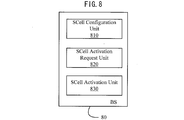
a secondary cell (SCell) configuration unit configured to generate secondary cell (SCell) configuration information and transmit it to a User Equipment (UE);
an SCell activation request unit configured to transmit an SCell activation request for the UE to a micro BS and receive from the micro BS an SCell activation response to the SCell activation request; and
an SCell activation unit configured to transmit SCell activation information to the UE if the received SCell activation response indicates that the SCell activation request is accepted by the micro BS,
wherein the SCell configuration information contains group numbers and indices of SCells associated with the BS and the micro BS, respectively, and indicates a secondary primary cell (S-PCell) associated with the micro BS. - The BS of claim 9, wherein the SCell configuration unit is further configured to set the group numbers of the SCells associated with the BS to be identical to each other and set the group numbers of the SCells associated with the micro BS to be identical to each other.
- The BS of claim 9, wherein the SCell configuration unit is further configured to set the group number of each SCell based on a Timing Advance (TA) group number corresponding to the SCell.
- The BS of claim 9, wherein the SCell configuration unit is further configured to number the indices of the SCells having different group numbers separately.
- The BS of claim 9, wherein the SCell configuration unit is further configured to number the indices of all the SCells jointly.
- The BS of claim 9, wherein the SCell configuration unit is further configured to select one of the SCells associated with the micro BS which has the largest or smallest index as the S-PCell associated with the micro BS.
- The BS of claim 9, wherein the SCell activation information contains a bit indicating a group number of an SCell to be activated.
- The BS of claim 9, wherein the group number of each SCell comprises a physical cell identifier.
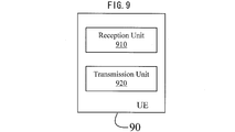
- A User Equipment (UE), comprising:
a reception unit configured to receive from a Base Station (BS) secondary cell (SCell) configuration information containing group numbers and indices of SCells associated with the BS and a micro BS, respectively, and indicating a secondary primary cell (S-PCell) associated with the micro BS; and
a transmission unit configured to transmit a Physical Uplink Control Channel (PUCCH) on an uplink component carrier corresponding to the S-PCell upon receiving the SCell activation information from the BS. - The UE of claim 17, wherein the group numbers of the SCells associated with the BS are identical to each other and the group numbers of the SCells associated with the micro BS are identical to each other.
- The UE of claim 17, wherein the S-PCell associated with the micro BS is one of the SCells associated with the micro BS which has the largest or smallest index.
- The UE of claim 17, wherein the SCell activation information contains a bit indicating a group number of an SCell to be activated.
Priority Applications (4)
| Application Number | Priority Date | Filing Date | Title |
|---|---|---|---|
| CA2880448A CA2880448C (en) | 2012-07-31 | 2013-07-30 | Method for component carrier configuration, base station and user equipment |
| JP2015523667A JP5933128B2 (en) | 2012-07-31 | 2013-07-30 | Component carrier setting method, base station, and user equipment |
| EP13825467.7A EP2880944B1 (en) | 2012-07-31 | 2013-07-30 | Method for component carrier configuration, base station and user equipment |
| US14/418,838 US11064466B2 (en) | 2012-07-31 | 2013-07-30 | Method for component carrier configuration, base station and user equipment |
Applications Claiming Priority (2)
| Application Number | Priority Date | Filing Date | Title |
|---|---|---|---|
| CN201210266541.X | 2012-07-31 | ||
| CN201210266541.XA CN103581918B (en) | 2012-07-31 | 2012-07-31 | component carrier configuration method, base station and user equipment |
Publications (1)
| Publication Number | Publication Date |
|---|---|
| WO2014020903A1 true WO2014020903A1 (en) | 2014-02-06 |
Family
ID=50027608
Family Applications (1)
| Application Number | Title | Priority Date | Filing Date |
|---|---|---|---|
| PCT/JP2013/004612 WO2014020903A1 (en) | 2012-07-31 | 2013-07-30 | Method for component carrier configuration, base station and user equipment |
Country Status (6)
| Country | Link |
|---|---|
| US (1) | US11064466B2 (en) |
| EP (1) | EP2880944B1 (en) |
| JP (1) | JP5933128B2 (en) |
| CN (1) | CN103581918B (en) |
| CA (1) | CA2880448C (en) |
| WO (1) | WO2014020903A1 (en) |
Cited By (8)
| Publication number | Priority date | Publication date | Assignee | Title |
|---|---|---|---|---|
| WO2015015285A3 (en) * | 2013-07-31 | 2015-12-10 | Alcatel Lucent | Method of supporting dual connectivity in a carrier aggregation based communication system |
| WO2016122108A1 (en) * | 2015-01-30 | 2016-08-04 | 주식회사 아이티엘 | Method and device for grouping serving cells in multiple component carrier system |
| JP2016143923A (en) * | 2015-01-29 | 2016-08-08 | 株式会社Nttドコモ | User device |
| JPWO2015151293A1 (en) * | 2014-04-04 | 2017-04-13 | 富士通株式会社 | Wireless communication system, base station and terminal |
| US10257778B2 (en) | 2014-04-16 | 2019-04-09 | Fujitsu Limited | Wireless communication system, base station, and terminal |
| US10321410B2 (en) | 2015-01-30 | 2019-06-11 | Huawei Technologies Co., Ltd. | Apparatus and method for performing uplink power control in wireless communication system supporting carrier aggregation |
| US10555298B2 (en) | 2014-04-11 | 2020-02-04 | Fujitsu Limited | Wireless communication system, base station, and terminal |
| DE112014005033B4 (en) | 2013-11-25 | 2023-03-30 | Taissa Research Llc | Method for sending a report to a base station by a terminal and device therefor |
Families Citing this family (19)
| Publication number | Priority date | Publication date | Assignee | Title |
|---|---|---|---|---|
| KR102156886B1 (en) * | 2012-09-25 | 2020-09-17 | 삼성전자주식회사 | Method and apparatus to utilizing a plurality of cells in a communication system |
| WO2014047892A1 (en) * | 2012-09-28 | 2014-04-03 | 华为技术有限公司 | Data transmission method, base station and user equipment |
| KR101832686B1 (en) * | 2013-09-10 | 2018-02-26 | 엘지전자 주식회사 | Method for determining uplink transmission timing of terminal having plurality of cells configured therein in wireless communication system, and apparatus using the method |
| US9900923B2 (en) * | 2013-11-01 | 2018-02-20 | Qualcomm Incorporated | Techniques for using carrier aggregation in dual connectivity wireless communications |
| CN110932835B (en) | 2014-01-29 | 2023-07-21 | 北京三星通信技术研究有限公司 | Method and apparatus for handling activation/deactivation of carrier aggregation between base stations |
| CN105323849B (en) * | 2014-06-30 | 2020-04-07 | 中兴通讯股份有限公司 | Configuration and sending method and device of uplink control channel, base station and user equipment |
| KR101875255B1 (en) * | 2014-08-07 | 2018-07-06 | 주식회사 케이티 | Methods for configuring carrier aggregation and Apparatuses thereof |
| WO2016026066A1 (en) * | 2014-08-16 | 2016-02-25 | 华为技术有限公司 | Method for simultaneously transmitting multiple uplink channels, base station, and user equipment |
| CN104640118B (en) * | 2015-01-30 | 2019-02-12 | 中兴通讯股份有限公司 | Cell group technology, sync fail processing method, base station and user equipment |
| KR101987525B1 (en) * | 2015-03-09 | 2019-06-12 | 주식회사 케이티 | Methods for transmitting channel state information and Apparatuses thereof |
| US10425921B2 (en) * | 2015-04-01 | 2019-09-24 | Acer Incorporated | Method of uplink control information transmission |
| WO2016159527A1 (en) * | 2015-04-01 | 2016-10-06 | Lg Electronics Inc. | Method for performing a pucch transmission on a deactivated pucch scell in a carrier aggregation system and a device therefor |
| US20160301513A1 (en) * | 2015-04-08 | 2016-10-13 | Intel IP Corporation | Systems, methods, and devices for component carrier management in carrier aggregation systems |
| EP3252985B1 (en) * | 2016-06-02 | 2019-07-31 | LG Electronics Inc. | Method and apparatus for transmitting uplink data in wireless communication system |
| KR102581594B1 (en) | 2016-07-19 | 2023-09-25 | 삼성전자 주식회사 | Method and Apparatus for carrier aggregation in a wireless communication system |
| US10819475B2 (en) * | 2016-08-12 | 2020-10-27 | Qualcomm Incorporated | Uplink semi-persistent scheduling for low latency communications |
| CN110012499B (en) * | 2018-01-04 | 2022-07-12 | 株式会社Kt | Method for controlling SCell state and apparatus therefor |
| EP3745765A4 (en) | 2018-02-13 | 2021-01-13 | Huawei Technologies Co., Ltd. | Communication method and device |
| WO2019157637A1 (en) * | 2018-02-13 | 2019-08-22 | 华为技术有限公司 | Communication method and device |
Citations (1)
| Publication number | Priority date | Publication date | Assignee | Title |
|---|---|---|---|---|
| WO2012022096A1 (en) * | 2010-08-16 | 2012-02-23 | 中兴通讯股份有限公司 | Method for reporting channel state information and base station |
Family Cites Families (16)
| Publication number | Priority date | Publication date | Assignee | Title |
|---|---|---|---|---|
| EP2613603B1 (en) * | 2009-04-23 | 2021-12-08 | InterDigital Patent Holdings, Inc. | Method and apparatus for random access in multicarrier wireless communications |
| JP5993740B2 (en) * | 2009-10-01 | 2016-09-14 | インターデイジタル パテント ホールディングス インコーポレイテッド | Transmit uplink control data |
| CN102263620B (en) * | 2010-05-28 | 2014-11-05 | 华为技术有限公司 | Method, device and system for feeding back multi-carrier response messages |
| US8446872B2 (en) * | 2010-06-18 | 2013-05-21 | Intel Mobile Communications GmbH | Communication terminal, communication device, method for data communication, and method for frequency allocation |
| EP2583398B1 (en) * | 2010-06-21 | 2014-08-06 | Telefonaktiebolaget LM Ericsson (publ) | Method and arrangement for signaling of parameters in a wireless network |
| CN101945403B (en) * | 2010-08-06 | 2016-01-20 | 中兴通讯股份有限公司 | A kind of method and apparatus determining the proprietary search volume of user |
| US8798663B2 (en) * | 2010-10-01 | 2014-08-05 | Acer Incorporated | Method of performing power headroom reporting and communication device thereof |
| US8717920B2 (en) * | 2010-10-08 | 2014-05-06 | Telefonaktiebolaget L M Ericsson (Publ) | Signalling mechanism for multi-tiered intra-band carrier aggregation |
| KR102073027B1 (en) * | 2011-04-05 | 2020-02-04 | 삼성전자 주식회사 | Method and appratus of operating multiple time alignment timer in mobile communication system using carrier aggregation |
| JP5895008B2 (en) * | 2011-03-18 | 2016-03-30 | エルジー エレクトロニクス インコーポレイティド | Method and apparatus for transmitting control information in wireless communication system |
| US9467959B2 (en) * | 2011-04-01 | 2016-10-11 | Mediatek, Inc. | Method of maintaining multiple timing advance |
| US8837304B2 (en) * | 2011-04-08 | 2014-09-16 | Sharp Kabushiki Kaisha | Devices for multi-group communications |
| TWI574532B (en) * | 2011-05-10 | 2017-03-11 | 內數位專利控股公司 | Method and apparatus for obtaining uplink timing alignment on a secondary cell |
| US20130182687A1 (en) * | 2011-07-28 | 2013-07-18 | Samsung Electronics Co., Ltd. | Apparatus and method for controlling secondary cell uplink synchronization states |
| US20130250908A1 (en) * | 2012-03-23 | 2013-09-26 | Nokia Siemens Networks Oy | Base station power savings and control thereof |
| CN102612045A (en) * | 2012-04-13 | 2012-07-25 | 北京邮电大学 | Energy saving method based on microcell cooperation in long-term evolution system |
-
2012
- 2012-07-31 CN CN201210266541.XA patent/CN103581918B/en active Active
-
2013
- 2013-07-30 EP EP13825467.7A patent/EP2880944B1/en active Active
- 2013-07-30 JP JP2015523667A patent/JP5933128B2/en active Active
- 2013-07-30 CA CA2880448A patent/CA2880448C/en active Active
- 2013-07-30 US US14/418,838 patent/US11064466B2/en active Active
- 2013-07-30 WO PCT/JP2013/004612 patent/WO2014020903A1/en active Application Filing
Patent Citations (1)
| Publication number | Priority date | Publication date | Assignee | Title |
|---|---|---|---|---|
| WO2012022096A1 (en) * | 2010-08-16 | 2012-02-23 | 中兴通讯股份有限公司 | Method for reporting channel state information and base station |
Non-Patent Citations (4)
| Title |
|---|
| "Technical Specification Group Radio Access Network; Evolved Universal Terrestrial Radio Access (E-UTRA) ; Radio Resource Control (RRC); Protocol specification(Release 10)", 3GPP TS 36.331 V10.6.0, June 2012 (2012-06-01), pages 46 - 50,59-62,128-129, XP055185184 * |
| NTT DOCOMO: "Views on UE-Specific UL RS Assignment", 3GPP TSG RAN WG1 MEETING #68 R1-120408, 10 February 2012 (2012-02-10), XP050563315 * |
| RWS-120010, NTT DOCOMO, REQUIREMENTS CANDIDATE SOLUTIONS & TECHNOLOGY ROADMAP FOR LTE REL-12 ONWARD, 11 June 2012 (2012-06-11) |
| See also references of EP2880944A4 |
Cited By (12)
| Publication number | Priority date | Publication date | Assignee | Title |
|---|---|---|---|---|
| WO2015015285A3 (en) * | 2013-07-31 | 2015-12-10 | Alcatel Lucent | Method of supporting dual connectivity in a carrier aggregation based communication system |
| DE112014005033B4 (en) | 2013-11-25 | 2023-03-30 | Taissa Research Llc | Method for sending a report to a base station by a terminal and device therefor |
| JPWO2015151293A1 (en) * | 2014-04-04 | 2017-04-13 | 富士通株式会社 | Wireless communication system, base station and terminal |
| US10575190B2 (en) | 2014-04-04 | 2020-02-25 | Fujitsu Limited | Wireless communication system, base station, and terminal for selecting at least one cell from among multiple cells |
| US10555298B2 (en) | 2014-04-11 | 2020-02-04 | Fujitsu Limited | Wireless communication system, base station, and terminal |
| US10257778B2 (en) | 2014-04-16 | 2019-04-09 | Fujitsu Limited | Wireless communication system, base station, and terminal |
| JP2016143923A (en) * | 2015-01-29 | 2016-08-08 | 株式会社Nttドコモ | User device |
| WO2016122108A1 (en) * | 2015-01-30 | 2016-08-04 | 주식회사 아이티엘 | Method and device for grouping serving cells in multiple component carrier system |
| KR20160094196A (en) * | 2015-01-30 | 2016-08-09 | 주식회사 아이티엘 | Method and apparatus for grouping serving cells |
| US10321410B2 (en) | 2015-01-30 | 2019-06-11 | Huawei Technologies Co., Ltd. | Apparatus and method for performing uplink power control in wireless communication system supporting carrier aggregation |
| US10785728B2 (en) | 2015-01-30 | 2020-09-22 | Huawei Technologies Co., Ltd. | Apparatus and method for performing uplink power control in wireless communication system supporting carrier aggregation |
| KR102244326B1 (en) * | 2015-01-30 | 2021-04-23 | 후아웨이 테크놀러지 컴퍼니 리미티드 | Method and apparatus for grouping serving cells |
Also Published As
| Publication number | Publication date |
|---|---|
| EP2880944A1 (en) | 2015-06-10 |
| CA2880448C (en) | 2018-08-14 |
| US11064466B2 (en) | 2021-07-13 |
| EP2880944B1 (en) | 2018-01-10 |
| JP2015526998A (en) | 2015-09-10 |
| EP2880944A4 (en) | 2016-03-23 |
| CN103581918B (en) | 2018-06-01 |
| JP5933128B2 (en) | 2016-06-08 |
| CN103581918A (en) | 2014-02-12 |
| US20150215926A1 (en) | 2015-07-30 |
| CA2880448A1 (en) | 2014-02-06 |
Similar Documents
| Publication | Publication Date | Title |
|---|---|---|
| CA2880448C (en) | Method for component carrier configuration, base station and user equipment | |
| JP6957835B2 (en) | Information transmission methods and devices | |
| CN106452705B (en) | Electronic device and wireless communication method in wireless communication system | |
| EP3143817B1 (en) | Apparatus and method for resource allocation for device-to-device communications | |
| US9386460B2 (en) | Systems and methods for carrier aggregation deployment and organization in unlicensed bands | |
| CN111435845B (en) | Communication method and communication device | |
| KR102225238B1 (en) | Data transmission method, terminal, and base station | |
| WO2015166801A1 (en) | Base-station device, terminal device, and communication method | |
| JP2017229068A (en) | Device and method for handling dual cellular system aggregation | |
| AU2017418048A1 (en) | Communication apparatus, method and computer program | |
| CN111386741B (en) | Link recovery method, terminal equipment and network equipment | |
| US20230361962A1 (en) | Electronic device, wireless communication method and computer readable medium | |
| CN113872740A (en) | Method and user equipment for wireless communication | |
| WO2016168967A1 (en) | Method and device for component carrier group configuration | |
| US10588058B2 (en) | User equipment, base station and communication method | |
| JP6564856B2 (en) | User equipment | |
| KR20200120701A (en) | Channel transmission method, apparatus and computer storage medium | |
| EP4131834A1 (en) | Srs signaling in 5g new radio wireless communications | |
| WO2023010414A1 (en) | Srs signaling in 5g new radio wireless communications | |
| WO2024060224A1 (en) | Aperiodic csi report with dormant bwp or scell | |
| KR20240052954A (en) | Methods for uplink control channel carrier switching | |
| CN117241399A (en) | Frequency domain resource allocation method and device |
Legal Events
| Date | Code | Title | Description |
|---|---|---|---|
| 121 | Ep: the epo has been informed by wipo that ep was designated in this application |
Ref document number: 13825467 Country of ref document: EP Kind code of ref document: A1 |
|
| ENP | Entry into the national phase |
Ref document number: 2015523667 Country of ref document: JP Kind code of ref document: A |
|
| ENP | Entry into the national phase |
Ref document number: 2880448 Country of ref document: CA |
|
| WWE | Wipo information: entry into national phase |
Ref document number: 14418838 Country of ref document: US |
|
| NENP | Non-entry into the national phase |
Ref country code: DE |
|
| WWE | Wipo information: entry into national phase |
Ref document number: 2013825467 Country of ref document: EP |
|
| WWE | Wipo information: entry into national phase |
Ref document number: IDP00201500942 Country of ref document: ID |