WO2014016862A1 - Display control program, display control method, and display control device - Google Patents
Display control program, display control method, and display control device Download PDFInfo
- Publication number
- WO2014016862A1 WO2014016862A1 PCT/JP2012/004673 JP2012004673W WO2014016862A1 WO 2014016862 A1 WO2014016862 A1 WO 2014016862A1 JP 2012004673 W JP2012004673 W JP 2012004673W WO 2014016862 A1 WO2014016862 A1 WO 2014016862A1
- Authority
- WO
- WIPO (PCT)
- Prior art keywords
- image
- display control
- marker
- reference object
- movement
- Prior art date
Links
Images


Classifications
-
- G—PHYSICS
- G06—COMPUTING; CALCULATING OR COUNTING
- G06T—IMAGE DATA PROCESSING OR GENERATION, IN GENERAL
- G06T19/00—Manipulating 3D models or images for computer graphics
- G06T19/006—Mixed reality
-
- G—PHYSICS
- G06—COMPUTING; CALCULATING OR COUNTING
- G06T—IMAGE DATA PROCESSING OR GENERATION, IN GENERAL
- G06T11/00—2D [Two Dimensional] image generation
- G06T11/60—Editing figures and text; Combining figures or text
-
- G—PHYSICS
- G06—COMPUTING; CALCULATING OR COUNTING
- G06F—ELECTRIC DIGITAL DATA PROCESSING
- G06F1/00—Details not covered by groups G06F3/00 - G06F13/00 and G06F21/00
- G06F1/16—Constructional details or arrangements
- G06F1/1613—Constructional details or arrangements for portable computers
- G06F1/1633—Constructional details or arrangements of portable computers not specific to the type of enclosures covered by groups G06F1/1615 - G06F1/1626
- G06F1/1684—Constructional details or arrangements related to integrated I/O peripherals not covered by groups G06F1/1635 - G06F1/1675
- G06F1/1686—Constructional details or arrangements related to integrated I/O peripherals not covered by groups G06F1/1635 - G06F1/1675 the I/O peripheral being an integrated camera
-
- G—PHYSICS
- G06—COMPUTING; CALCULATING OR COUNTING
- G06F—ELECTRIC DIGITAL DATA PROCESSING
- G06F1/00—Details not covered by groups G06F3/00 - G06F13/00 and G06F21/00
- G06F1/16—Constructional details or arrangements
- G06F1/1613—Constructional details or arrangements for portable computers
- G06F1/1633—Constructional details or arrangements of portable computers not specific to the type of enclosures covered by groups G06F1/1615 - G06F1/1626
- G06F1/1684—Constructional details or arrangements related to integrated I/O peripherals not covered by groups G06F1/1635 - G06F1/1675
- G06F1/1694—Constructional details or arrangements related to integrated I/O peripherals not covered by groups G06F1/1635 - G06F1/1675 the I/O peripheral being a single or a set of motion sensors for pointer control or gesture input obtained by sensing movements of the portable computer
-
- G—PHYSICS
- G06—COMPUTING; CALCULATING OR COUNTING
- G06F—ELECTRIC DIGITAL DATA PROCESSING
- G06F3/00—Input arrangements for transferring data to be processed into a form capable of being handled by the computer; Output arrangements for transferring data from processing unit to output unit, e.g. interface arrangements
- G06F3/01—Input arrangements or combined input and output arrangements for interaction between user and computer
- G06F3/011—Arrangements for interaction with the human body, e.g. for user immersion in virtual reality
-
- G—PHYSICS
- G06—COMPUTING; CALCULATING OR COUNTING
- G06F—ELECTRIC DIGITAL DATA PROCESSING
- G06F3/00—Input arrangements for transferring data to be processed into a form capable of being handled by the computer; Output arrangements for transferring data from processing unit to output unit, e.g. interface arrangements
- G06F3/01—Input arrangements or combined input and output arrangements for interaction between user and computer
- G06F3/03—Arrangements for converting the position or the displacement of a member into a coded form
- G06F3/0304—Detection arrangements using opto-electronic means
-
- G—PHYSICS
- G06—COMPUTING; CALCULATING OR COUNTING
- G06T—IMAGE DATA PROCESSING OR GENERATION, IN GENERAL
- G06T7/00—Image analysis
- G06T7/20—Analysis of motion
- G06T7/246—Analysis of motion using feature-based methods, e.g. the tracking of corners or segments
-
- G—PHYSICS
- G09—EDUCATION; CRYPTOGRAPHY; DISPLAY; ADVERTISING; SEALS
- G09G—ARRANGEMENTS OR CIRCUITS FOR CONTROL OF INDICATING DEVICES USING STATIC MEANS TO PRESENT VARIABLE INFORMATION
- G09G3/00—Control arrangements or circuits, of interest only in connection with visual indicators other than cathode-ray tubes
- G09G3/001—Control arrangements or circuits, of interest only in connection with visual indicators other than cathode-ray tubes using specific devices not provided for in groups G09G3/02 - G09G3/36, e.g. using an intermediate record carrier such as a film slide; Projection systems; Display of non-alphanumerical information, solely or in combination with alphanumerical information, e.g. digital display on projected diapositive as background
- G09G3/002—Control arrangements or circuits, of interest only in connection with visual indicators other than cathode-ray tubes using specific devices not provided for in groups G09G3/02 - G09G3/36, e.g. using an intermediate record carrier such as a film slide; Projection systems; Display of non-alphanumerical information, solely or in combination with alphanumerical information, e.g. digital display on projected diapositive as background to project the image of a two-dimensional display, such as an array of light emitting or modulating elements or a CRT
-
- G—PHYSICS
- G06—COMPUTING; CALCULATING OR COUNTING
- G06T—IMAGE DATA PROCESSING OR GENERATION, IN GENERAL
- G06T2207/00—Indexing scheme for image analysis or image enhancement
- G06T2207/10—Image acquisition modality
- G06T2207/10004—Still image; Photographic image
-
- G—PHYSICS
- G06—COMPUTING; CALCULATING OR COUNTING
- G06T—IMAGE DATA PROCESSING OR GENERATION, IN GENERAL
- G06T2207/00—Indexing scheme for image analysis or image enhancement
- G06T2207/10—Image acquisition modality
- G06T2207/10016—Video; Image sequence
-
- G—PHYSICS
- G06—COMPUTING; CALCULATING OR COUNTING
- G06T—IMAGE DATA PROCESSING OR GENERATION, IN GENERAL
- G06T2207/00—Indexing scheme for image analysis or image enhancement
- G06T2207/30—Subject of image; Context of image processing
- G06T2207/30204—Marker
-
- G—PHYSICS
- G06—COMPUTING; CALCULATING OR COUNTING
- G06T—IMAGE DATA PROCESSING OR GENERATION, IN GENERAL
- G06T2215/00—Indexing scheme for image rendering
- G06T2215/16—Using real world measurements to influence rendering
Definitions
- the present invention relates to display control technology.
- Identification that can measure the relative position and relative orientation (relative angle) between the reference object and the image sensor based on the image of the reference object reflected in the captured image.
- the body is used.
- an identifier called an AR (Augmented Reality) marker is used as a reference object.
- the AR marker is, for example, a printed matter on which a pattern (pattern) capable of measuring a relative position and a relative angle with respect to the imaging element is printed based on a captured image obtained by capturing the AR marker itself.
- Some AR markers can acquire information from the AR marker by analyzing a pattern printed on the AR marker based on the image of the AR marker in the captured image.
- the read image is readjusted according to the relative position and relative angle between the reference object and the image sensor.
- the display position and size of the projected image that matches the updated captured image are unknown, Control to end the display is performed.
- the display of the projected image that may not match the captured image can be terminated by the execution control of the projected image display according to the determination whether the image of the reference object is included in the captured image. .
- the shooting range does not change, if an obstacle enters between the image sensor and the reference object, the reference object is hidden behind the obstacle, so the image of the reference object is not included in the shooting information. .
- the display of the projection image is terminated based on the non-recognition of the reference object, the display of the projection image is terminated even though the projection image that matches the captured image can be displayed. It will be.
- An object of one aspect of the present disclosure is to prevent the display of a projection image from being terminated even though a projection image that matches a captured image can be displayed.
- the display control program acquires a captured image from the image sensor to the computer, acquires a movement amount of the image sensor, and recognizes an image of the reference object from the captured image acquired from the image sensor.
- display control of the image model adjusted according to the positional relationship between the reference object and the image sensor is started, and the reference object is recognized from within the captured image acquired from the image sensor.
- the display control is continued and the process is executed.
- the Display control of the image model adjusted according to the positional relationship between the reference object and the image sensor is started, and the display control is performed when the reference object is recognized from within the captured image acquired from the image sensor.
- the display control is continued when the reference object is not recognized from the captured image acquired from the image sensor and the amount of movement is less than the predetermined amount.
- the display control apparatus acquires an image capturing unit, a sensor unit that measures a motion amount of the image capturing unit, a captured image from the image capturing unit, and acquires the motion amount from the sensor unit. And when starting the display control of the image model adjusted according to the positional relationship between the reference object and the image sensor when the image of the reference object is recognized from within the captured image acquired from the imaging unit.
- the display control is continued, and after the reference object is recognized, the reference object from within the captured image acquired from the imaging unit.
- a control unit that continues the display control when the amount of movement is less than the predetermined amount.
- FIG. 1A-C show the relationship between the marker and the projected image.
- FIG. 2 shows a system configuration example of the present embodiment.
- FIG. 3 shows a configuration example of functional blocks of the terminal device 1.
- FIG. 4 shows a hardware configuration example of the terminal device 1.
- FIG. 5 shows a functional block configuration example of the server device 2.
- FIG. 6 shows a hardware configuration example of the server device 2.
- 7A and 7B show configuration examples of programs operating on the terminal device 1 and the server device 2, respectively.
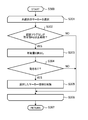
- FIG. 8 shows a flowchart example of display control.
- 9A and 9B show examples of the data structure of the recognition management table T1 and the storage area R1 for storing the recognition results, respectively.
- FIG. 10 shows an example of the marker coordinate table T2.
- FIG. 11 shows an example of a flowchart of marker recognition processing.
- FIG. 12 shows a flowchart example of update processing of the recognition management table T1.
- FIGS. 13A to 13C show examples of temporal changes of the acceleration Ax, the velocity Vx, and the position coordinate Lx, respectively.
- FIG. 14 shows a flowchart example of the movement amount calculation process.
- 15A and 15B show examples of the coordinate table T3 and the movement amount table T4.
- FIG. 16 shows a flowchart of the image generation process.
- FIG. 17 shows an example of the projection image management table T5.
- 18A and 18B show the relationship between the marker coordinate system and the camera coordinate system, and the screen coordinate system, respectively.
- 19A and 19B show examples of the transformation matrix X1 and the transformation matrix X2, respectively.
- FIG. 20 shows a configuration example of functional blocks of the terminal device 1.
- FIG. 21 shows a configuration example of a program of the terminal device 1.
- FIG. 22 shows a configuration example of functional blocks of the server device 2.
- FIG. 23 shows a configuration example of a program of
- a marker such as an AR marker is used as a reference object when a projected image is superimposed and displayed on a display device that displays a captured image obtained from a camera or the like in real time.
- the marker is an identifier that can calculate a relative position and a relative angle with respect to an image sensor that captures an image based on an image of the marker itself that appears in the captured image.
- the projection image is obtained, for example, by adjusting the projection angle and size of an image model in which the positional relationship from the marker is defined based on the relative position and relative angle of the marker.
- the image model may have a shape and a surface pattern (pattern) defined in advance, or may be processed based on a captured image.
- the image model itself includes a one-dimensional model, a two-dimensional model, and a three-dimensional model.
- the model itself is defined by one-dimensional coordinates or two-dimensional coordinates, it may be expressed as three-dimensional coordinates by giving constant coordinates in directions not defined.
- the projection image is displayed not only on the display device that displays the captured image but also on, for example, a transmissive display. When the projection image is displayed on the transmissive display, for example, the projection image adjusted to match the image viewed through the transmissive display is displayed.
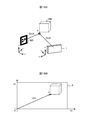
- FIGS. 1A to 1C are explanatory diagrams of the relationship between a marker and a projected image.
- a frame F indicates a range captured by the image sensor, and an inside of the frame F indicates an example of a display screen that displays a captured image and a projected image.
- the content that is actually displayed is indicated by a solid line, and the content that is not actually displayed is indicated by a dotted line (except for an arrow).
- FIG. 1A shows a display example of a projected image when a marker is recognized.
- an image of the marker M1 is included in the captured image.
- the projected image PI1 is generated by adjusting an image model defined with the marker M1 as a reference based on the relative position and relative angle of the marker.
- a position such as where the marker exists (corresponding to an arrow in FIG. 1), what shape it is in (a cube is illustrated in FIG. 1), etc. are specified. Is included.
- the marker M1 illustrated in FIG. 1A is oriented substantially parallel to the image sensor, and an arrow indicating where the image model is located with respect to the marker M1 is substantially on the surface of the marker M1. To do. For this reason, the depths of the marker M1 and the projected image PI1 are displayed to be approximately the same.
- the projected image PI2 is a projected image of an image model in which the same definition as the projected image PI1 is made with reference to the marker M2.
- the marker M2 is reflected at a shallower angle than the marker M1. Therefore, the projected image PI2 with the marker M2 as a reference is displayed with a depth different from that of the marker M2.
- the display position, size, and orientation of the projection image defined with the marker as a reference are adjusted according to the marker image (how it is projected).
- FIG. 1B shows an example of a captured image when the marker is out of frame.
- the image of the marker M3 is not included in the frame F.
- the projection image (projection image PI3) corresponding to the image model is not displayed. That is, when the marker image is out of frame, the display reference is unclear, and the display of the projected image is interrupted.
- the projected image PI3 is indicated by a dotted line in order to conveniently indicate that there is a 3D model defined based on the marker M3, but the marker M3 is not displayed because it is not recognized.
- the camera when displaying a projected image based on a certain marker and then displaying a projected image based on another marker, the camera is directed to another imaging target. Frame out can occur.
- the projection image display reference is switched by the frame out of the marker previously used as a reference and the frame in of a marker as a new reference.
- the marker will be out of frame when the operator performs another operation (such as an operation to end the superimposed display or an input operation to the terminal), and the projection image display ends at a timing in line with the operator's intention. It becomes.
- FIG. 1C shows an example of a captured image when a marker cannot be recognized due to an obstacle (in the example of FIG. 1C, an operator's hand).
- the marker M4 is within the frame F, but the image of the marker M4 cannot be identified due to the presence of an obstacle. Therefore, the display of the projection image PI4 with the marker M4 as a reference is interrupted.
- the interruption of the projected image display due to an obstacle is different from the interruption due to the out-of-frame according to the operator's intention such as moving the frame to another shooting target or shifting the operator to another operation. This can also occur when trying to display a projected image.
- the operator intends to continue displaying the projected image, if the projected image display is interrupted without obeying the intention due to an obstacle, the operability is impaired.
- a scenario in which a plurality of projection images are displayed in order in an application program that uses display of projection images.
- the scenario returns to the start point.
- the application program itself is provided with a scenario recovery mechanism when the display of the projected image is interrupted. For such a situation, not only the determination that the marker image is not included in the captured image, but also that the projection image display is interrupted only when it is detected that the imaging element itself has moved. By doing so, interruption of projection image display unintended by the operator is suppressed.
- FIG. 2 shows the system configuration of this embodiment.
- the system shown in FIG. 2 includes a terminal device 1, a server device 2, a storage device 3, a network 4, and a base station 5.
- the terminal device 1 and the server device 2 can communicate with each other by at least one of a wired or wireless communication method.
- the server device 2 can access the database 3 a included in the storage device 3.
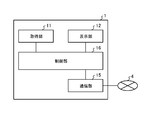
- FIG. 3 shows a functional block configuration of the terminal device 1.
- the terminal device 1 includes an acquisition unit 11, a display unit 12, a control unit 13, a storage unit 14, and a communication unit 15.
- the acquisition unit 11 acquires information measured by a sensor provided in the terminal device 1.
- the information acquired by the acquisition unit 11 is, for example, an image captured by the image sensor or information indicating the amount of movement of the terminal device 1 (such as a value measured by an acceleration / angular velocity sensor).
- the acquisition unit 11 acquires information at a set time interval.
- the display unit 12 displays an image under the control of the control unit 13. For example, as in the screens shown in FIGS. 1A to 1C, the captured image acquired by the acquisition unit 11 and the projection image are displayed.
- the control unit 13 performs processing according to the information acquired by the acquisition unit 11 and the information acquired via the communication unit 15, and controls the display unit 12 and the communication unit 15.
- the storage unit 14 stores information used for processing in the control unit 13. For example, a recognition management table T1, a marker coordinate table T2, a coordinate table T3, a movement amount table T4, a projection image management table T5 shown in FIG.
- the communication unit 15 communicates with a device such as the server device 2 under the control of the control unit 13.
- the control unit 13 acquires the definition information of the 3D model from the storage unit 12 or acquires it from the server device 2 through communication of the communication unit 15. That is, while there is a mode in which the terminal device 1 operates alone, there may be a mode in which the terminal device 1 and the server device 2 perform processing in cooperation.
- the control unit 13 includes a recognition determination unit 131, a movement determination unit 132, a coordinate calculation unit 133, and an image generation unit 134.
- the recognition determination unit 131 determines whether the marker is recognized according to the information acquired by the acquisition unit 11.
- the recognition determination unit 131 determines whether or not the marker image is included in the captured image and whether or not the terminal device 1 has moved. For example, the recognition determination unit 131 periodically determines whether or not a marker image is included in the captured image, and when the marker image in the recognition state no longer includes the image in the captured image, It is determined whether or not to cancel the recognition state of the marker according to the movement amount of the terminal device 1 main body.
- the movement determination unit 132 calculates the movement amount of the terminal device 1 in response to the call of the recognition determination unit 131.
- the recognition determination unit 131 determines whether or not the main body of the terminal device 1 has moved according to the movement amount calculated by the movement determination unit 132.
- the movement amount calculation by the movement determination unit 132 is calculated based on, for example, the measurement values of the acceleration sensor and the angular velocity sensor acquired by the acquisition unit 11.
- the movement determination unit 132 calculates a movement prediction amount based on the history of the marker position coordinates, and the recognition determination unit 131 determines whether to cancel the marker recognition state based on the movement prediction amount. May be.
- the coordinate calculation unit 133 performs a process of calculating the relative position and the relative angle between the marker and the image sensor based on the marker image included in the captured image in response to the call of the recognition determination unit 131. Furthermore, the coordinate calculation unit 133 performs coordinate conversion of each vertex included in the 3D model in response to the call of the image generation unit 134. Specifically, the coordinate calculation unit 133 converts coordinates defined in a coordinate system with the marker as a reference into coordinates indicating a position in the display screen when the 3D model is displayed on the screen. This coordinate conversion is performed based on the previously calculated relative position and relative angle of the marker.
- the image generation unit 134 converts the 3D model associated with the marker recognized by the recognition determination unit 131 into a 3D model based on the coordinates of each vertex converted by the coordinate calculation unit 133 and the definition of the 3D model. A corresponding projection image is generated.
- the control unit 13 performs control to display the image generated by the image generation unit 134 on the display unit 12.
- FIG. 4 shows the hardware configuration of the terminal device 1.
- the terminal device 1 includes, for example, a processor 301, a RAM (Random Access Memory) 302, a ROM (Read Only Memory) 303, a drive device 304, a storage medium 305, an input interface (input I / F) 306, an input device 307, and an output interface. (Output I / F) 308, output device 309, communication interface (communication I / F) 310, camera module 311, acceleration sensor 312, angular velocity sensor 313, bus 314, and the like. Each piece of hardware is connected via a bus 314.
- the communication interface 310 controls communication via the network 4.
- the communication controlled by the communication interface 310 may have a mode in which the network 4 is accessed via the base station 5.
- the input interface 306 is connected to the input device 307 and transmits an input signal received from the input device 307 to the processor 301.
- the output interface 308 is connected to the output device 309 and causes the output device 309 to execute output in accordance with an instruction from the processor 301.
- the input device 307 is a device that transmits an input signal according to an operation.
- the input signal is, for example, a keyboard or a key device such as a button attached to the main body of the terminal device 1 or a pointing device such as a mouse or a touch panel.
- the output device 309 is a device that outputs information according to the control of the terminal device 1.
- the output device 309 is, for example, an image output device (display device) such as a display, or an audio output device such as a speaker.
- a transmissive display may be used as the display device.
- an input / output device such as a touch screen is used as the input device 307 and the output device 309.
- the input device 307 and the output device 309 are not included in the terminal device 1 and may be devices connected to the terminal device 1 from the outside, for example.
- the RAM 302 is a readable / writable memory device.
- a semiconductor memory such as SRAM (Static RAM) or DRAM (Dynamic RAM), or a flash memory other than the RAM may be used.
- the ROM 303 includes a PROM (Programmable ROM).
- the drive device 304 is a device that performs at least one of reading and writing of information recorded in the storage medium 305.
- the storage medium 305 stores information written by the drive device 304.
- the storage medium 305 is, for example, a storage medium such as a hard disk, a CD (Compact Disc), a DVD (Digital Versatile Disc), or a Blu-ray disc.
- the computer 1 includes a drive device 304 and a storage medium 305 for each of a plurality of types of storage media.
- the camera module 311 includes an image sensor (image sensor). For example, the camera module 311 reads a value measured by the image sensor and writes it in an image buffer for an input image included in the camera module 311.
- the acceleration sensor 312 measures acceleration acting on the acceleration sensor 312.
- the angular velocity sensor 313 measures the angular velocity of the operation by the angular velocity sensor 313.
- the processor 301 reads a program (for example, a program illustrated in FIG. 7A and FIG. 22) stored in the ROM 303 and the storage medium 305 to the RAM 302, and performs processing of the control unit 13 according to the read program procedure. At that time, the RAM 302 is used as a work area of the processor 301.
- the function of the storage unit 14 is realized by the ROM 303 and the storage medium 305 storing program files and data files, or by using the RAM 302 as a work area of the processor 301.
- the camera module 311 generates image data
- the processor 301 acquires the generated image data
- the processor 301 acquires values measured by the acceleration sensor 312 and the angular velocity sensor 313, whereby the acquisition unit 11 Function is realized.
- the image data delivered from the camera module 311 to the processor 301 is accumulated in an input image buffer provided in the camera module 311, and the processor 301 reads the image data from the input image buffer.
- the processor 301 generates image data for output, and the generated image data is displayed on the display device that is the output device 309, thereby realizing the function of the display unit 12.
- the output image data generated by the processor 301 is written in an output image buffer provided in the output interface 308, and the display device reads the image data from the output image buffer and displays the read image data.
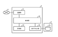
- FIG. 5 shows a functional block configuration example of the server apparatus 2.
- the server device 2 includes a communication unit 21, a control unit 22, a storage unit 23, and a DB access unit 24.
- the communication unit 21 communicates with the terminal device 1 under the control of the control unit 22.
- the control unit 22 reads information from the storage unit 23 and causes the communication unit 21 to transmit the read information to the terminal device 1.
- the DB access unit 24 reads information from the database 3 a included in the storage device 3, and causes the communication unit 21 to transmit the read information to the terminal device 1.
- the information requested to be acquired from the terminal device 1 is, for example, 3D model definition information associated with the marker.
- the storage unit 23 stores 3D model definition information and the like, and the DB access unit 24 accesses the database 3 a included in the storage device 3 under the control of the control unit 22.
- FIG. 6 shows the hardware configuration of the server device 2.
- the server device 2 includes, for example, a processor 401, a RAM (Random Access Memory) 402, a ROM (Read Only Memory) 403, a drive device 404, a storage medium 405, an input interface (input I / F) 406, an input device 407, and an output interface.
- (Output I / F) 408, output device 409, communication interface (communication I / F) 410, SAN (Storage Area Network) interface (SAN I / F) 411, bus 412 and the like are included.
- Each piece of hardware is connected via a bus 412.
- the communication interface 410 controls communication via the network 4.
- the input interface 406 is connected to the input device 407 and transmits an input signal received from the input device 407 to the processor 401.
- the output interface 408 is connected to the output device 409 and causes the output device 409 to execute output in accordance with an instruction from the processor 401.
- the input device 407 is a device that transmits an input signal according to an operation.
- the input signal is, for example, a key device such as a keyboard or a button attached to the main body of the server device 2 or a pointing device such as a mouse or a touch panel.
- the output device 409 is a device that outputs information in accordance with the control of the server device 2.
- the output device 409 is, for example, an image output device (display device) such as a display, or an audio output device such as a speaker.
- an input / output device such as a touch screen is used as the input device 407 and the output device 409.
- the input device 407 and the output device 409 are not included in the server device 2 and may be devices connected to the server device 2 from the outside, for example.
- the RAM 402 is a readable / writable memory device.
- a semiconductor memory such as SRAM (Static RAM) or DRAM (Dynamic RAM), or a flash memory other than the RAM may be used.
- the ROM 403 includes a PROM (Programmable ROM).
- the drive device 404 is a device that performs at least one of reading and writing of information recorded on the storage medium 405.
- the storage medium 405 stores information written by the drive device 404.
- the storage medium 405 is a storage medium such as a hard disk, a CD (Compact Disc), a DVD (Digital Versatile Disc), or a Blu-ray disc.
- the server device 2 includes a drive device 404 and a storage medium 405 for each of a plurality of types of storage media.
- the processor 401 reads a program (for example, the program illustrated in FIG. 7B or FIG. 23) stored in the ROM 403 or the storage medium 405 to the RAM 402, and performs the processing of the control unit 22 according to the read program procedure. At that time, the RAM 402 is used as a work area of the processor 401.
- the functions of the storage unit 23 are realized by the ROM 403 and the storage medium 405 storing program files and data files (projection image definition information (CAD data) or the like), or the RAM 402 is used as a work area of the processor 401. Is done.
- the SAN interface 411 operates in accordance with the control of the processor 401, thereby realizing the function of the DB access unit 24 such as access processing to the database 3a.
- FIG. 7A shows a configuration example of a program operating on the terminal device 1.
- an OS Operating System
- the processor 301 operates in accordance with the procedure in accordance with the OS 502, and the hardware 501 is controlled and managed, whereby the processing by the application program 504 and the middleware 503 is executed by the hardware 501.
- programs such as the OS 502, middleware 503, and application program 504 are read into the RAM 302 and executed by the processor 301.
- the processor 301 performs processing based on the middleware 503 (the hardware 501 is controlled based on the OS 502), the acquisition unit 11, the display unit 12, the control unit 13, the storage unit 14, and The function of the communication unit 15 is realized.
- the middleware 503 and the application program 504 may be separate programs that execute linked operations or may be integrated programs.
- a procedure of processing using the display control function of the projected image of the middleware 503 is shown. For example, a scenario of displaying a projection image, a detection of an input corresponding to the display, and a display control of the projection image corresponding to the input may be determined.
- the association flag of the model associated with the marker ID may be changed in the projection image management table T5 described later.
- FIG. 7B shows a configuration example of a program operating on the server device 2.
- an OS 602 that controls a hardware group 601 (hardware shown in FIG. 6) operates.
- the processor 401 operates in accordance with the procedure in accordance with the OS 602, and the hardware 601 is controlled and managed, whereby the processing by the application program 604 and the middleware 603 is executed by the hardware 601.
- programs such as the OS 602, middleware 603, and application program 604 are read into the RAM 402 and executed by the processor 401.
- the processor 401 performs processing based on the middleware 403 (the processing of the hardware 601 is performed based on the OS 602), the communication unit 21, the control unit 22, the storage unit 23, and the DB access unit 24.
- the function is realized.
- the middleware 603 and the application program 604 may be separate programs that execute linked operations or may be integrated programs.
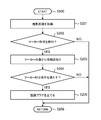
- FIG. 8 shows a flowchart of display control in the terminal device 1.
- the control unit 13 performs preprocessing (S101).
- the projection image display function is called, for example, by processing according to the procedure of the application program 504.
- the control unit 13 starts a movement amount calculation flow based on acceleration / angular velocity, secures storage areas for the recognition management table T1 and the marker coordinate table T2, reads the projection image management table T5, and the like. To do. Further, the control unit 13 initializes the value of the counter CT1.
- the recognition determination unit 131 performs marker recognition processing based on the captured image acquired from the acquisition unit 11 (S102).
- the marker recognition process in S102 will be described later with reference to FIG.
- the marker recognition process is performed, for example, at a time interval I2.
- the time interval T2 is, for example, one to several times the time interval T1 for writing the image read by the camera module 311 in the input image buffer.
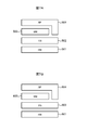
- FIG. 9A shows the recognition management table T1.
- the recognition management table T1 includes marker identification information (marker ID) recognized by the recognition determination unit 131, coordinates (Xr, Yr) indicating the position of the recognized marker in the screen, and a pointer indicating the storage destination of the recognition result.
- the marker ID is information read out by performing image analysis on the marker image in the captured image.
- the marker ID is information that can uniquely identify each marker provided, for example.
- the marker ID may include information specifying the size of the marker, for example. If the marker size can be read from the marker ID and the coordinate calculation unit 133 calculates the relative position and the relative angle of the marker according to the marker size, the terminal device 1 supports a plurality of types of markers having different sizes. Can be processed.
- the in-screen position (Xr, Yr) of the marker stored in the recognition management table T1 may be the center coordinates of the marker image included in the captured image, for example, if the marker itself is a quadrangle, The four coordinates shown may be used.
- the in-screen position (Xr, Yr) of the marker is used, for example, in searching for the reading position of the marker image when calculating the relative position and relative angle with the marker.
- FIG. 9A the latest position of the marker on the screen is stored, but the history of the marker position (Xr, Yr) is left several times, and the history of the marker position on the screen is moved. It may be used for prediction.
- the recognition result is stored in the storage area R1 illustrated in FIG. 9B.
- the storage area R1 is, for example, a storage area that can store a plurality of bit strings of a predetermined number N1 (16 in the example of FIG. 9B) bits.
- one bit string is assigned to store the recognition result of one marker.
- the recognition result of the marker with the marker ID “0000” is indicated by a bit string indicating the start position by the pointer PT1.
- the marker recognition result is stored at a position shifted by i ⁇ 1 bits from the position indicated by the pointer PT1.
- the start position of the bit string indicating the recognition result of the marker having the marker ID “0000” is indicated by the pointer PT1 stored in the recognition management table T1.
- the bit at a position shifted by 8 bits from the position indicated by the pointer PT1 is “1”.
- the storage area of the predetermined number N1 bits is repeatedly used every time a predetermined number N1 of recognition determinations are made. In the example of FIG.
- the recognition result of the 18th recognition determination is reflected in the bit at a position shifted by 1 bit from the position indicated by the pointer PT1.
- the storage area R1 shown in FIG. 9B is repeatedly used every time 16 ⁇ I2 seconds elapse.
- FIG. 10 shows the marker coordinate table T2.
- a marker ID for each marker recognized by the recognition determination unit 131, a marker ID, position coordinates (Xs, Ys, Zs) indicating a relative position with the image sensor, and a relative angle with the image sensor are shown.
- Angular coordinates (Ps, Qs, Rs) are stored.
- Ps indicates the rotation angle around the x-axis of the image sensor reference coordinate system
- Qs indicates the rotation angle around the y-axis
- Rs indicates the rotation angle around the z-axis.
- the recognition determination unit 131 reads the marker information and reflects the read information in the recognition management table T1 and the storage area R1 (when the marker is recognized as described above, for example, the correspondence in the storage area) Set the value to "1").
- the recognition determination unit 131 performs an update process of the recognition management table T1 based on the result of the marker recognition process of S102 (S103).
- the recognition determination unit 131 deletes information regarding markers that have not been continuously recognized by a predetermined number N2 or more from the recognition management table T1.
- the predetermined number N2 is a number equal to or less than the predetermined number N1.
- the marker recognition process is performed at the time interval I2, when the marker is not recognized for N2 ⁇ I2 seconds, information regarding the marker is deleted from the recognition management table T1. For example, by deleting only the markers that are not continuously recognized in a plurality of determinations, it is possible to prevent the information of the markers that are not recognized due to the marker recognition error from being inadvertently deleted.
- the recognition determination unit 131 increments the value of the counter CT1 (S104), and further determines whether or not the value of the counter CT1 has reached a predetermined value N3 ( S105).
- the predetermined value T3 is, for example, any number from 1 to N1.
- the coordinate calculation unit 133 determines that each of the markers whose information is stored in the recognition management table T1 in FIG. Relative coordinates (Xs, Ys, Zs) and relative angles (Ps, Qs, Rs) are calculated, and the calculated coordinates are stored in the marker coordinate table T2 (S106).
- the value of the counter CT1 is reset.
- the area corresponding to the value of the counter CT1 in the storage area R1 is cleared (for example, the value is set to “0”).
- the bit to be cleared is each bit at the position shifted by the value of the counter CT1 from the position indicated by each pointer in each bit string in the storage area R1. After clearing the bit, the recognition determination unit 131 performs the process of S102 again.
- control unit 13 When the control unit 13 finishes the process of S106, the control unit 13 calls a projection image display routine (S107). After the process of S107, the control unit 13 determines whether or not an instruction to end the projection image display function is input (S108). If the end instruction is not input (S108: NO), the control unit 13 executes the process of S102 again. If the end instruction is input (S108: YES), the control flow of the projection image display control ends. (S109).
- FIG. 11 shows a flowchart of marker recognition processing.
- the recognition determination unit 131 reads the captured image acquired by the acquisition unit 11 (S201).
- the reading of the captured image in S201 may be performed for each frame written in the input image buffer, or one of the designated number of frames may be read.
- the designation of the number of frames may be determined in advance or may be changed according to the processing load or the like during the processing.
- the number of frames depends on, for example, how long the time interval I2 at which the acquisition unit 11 reads an image from the input image buffer is longer than the time interval I1 at which the captured image is written into the input image buffer. Determined.
- the recognition determination unit 131 determines whether or not a marker image is included in the captured image read in S201 (S202).
- the determination in S202 is made based on whether or not a recognition target marker is a marker having the shape shown in FIG. In that case, for example, a plurality of types of patterns of images near the four vertices are stored in advance, and whether or not the captured image includes four images that match a combination of images stored near the four vertices in advance. Whether or not the marker exists is determined based on the above. In order to make a determination by this method, image combinations are prepared when the markers are directed in various directions.
- the recognition determination unit 131 acquires information by analyzing the marker image (S203).
- the information acquired by the recognition determination unit 131 in S203 includes, for example, coordinates (Xr, Yr) indicating the display position of the marker image, a marker ID decoded from the marker pattern, and the like.
- the coordinates (Xr, Yr) indicating the display position are, for example, the center coordinates of the marker image and the coordinates of the four vertices of the marker image.
- the marker ID is read based on the pattern in the marker.
- the marker ID is extracted, for example, based on a pattern included in the deformed image by deforming the detected marker image (which has a shape close to a parallelogram or trapezoid) into a square. For example, when the deformed image is binarized, the binarized array of “1” and “0” may be used as the marker ID as it is.
- the recognition determination unit 131 determines whether or not the marker ID acquired in S203 satisfies the condition CD1 (S204).
- the predetermined condition CD1 is that the size of the marker ID is a predetermined number of bits, and the value of the marker ID is within a predetermined range.
- the condition CD1 may be specified by processing based on the application program 504. For example, when using an application program on the assumption that information such as a mobile phone number is used as identification information, the marker ID is a numerical value of 11 digits or a numerical value starting from “090” or the like. Is a predetermined condition CD1. Further, the condition CD1 is not set, and the process of S204 may be performed without performing the determination of S203.
- the recognition determining unit 131 stores information related to the marker (marker ID, marker display position (Xr, Yr), and recognition result. (Pointer to bit string) is stored in the recognition management table T1 (S205). More specifically, in S205, the recognition determination unit 131 determines whether or not the read marker ID is already stored in the recognition management table T1. If the read marker ID is already stored in the recognition management table T1, the recognition determination unit 131 updates the recognition management table T1 and reflects the recognition result in the storage area R1.
- the recognition determination unit 131 adds a new record to the recognition management table T1 and reflects the recognition result in the storage area R1. As described above, the recognition determining unit 131 updates the bit in the order indicated by the value of the counter CT1 to “1” (indicating recognition) in the bit string corresponding to the read marker ID in the storage area R1.
- the process of S205 is finished, the process of S103 is performed (S206). The process of S206 is also performed when the marker cannot be detected in S202 (S202: NO) or when the marker ID read in S203 does not satisfy the condition CD1 (S204: NO).
- FIG. 12 shows a flowchart of the update process of the recognition management table T1.
- the recognition determination unit 131 selects one of the marker IDs stored in the recognition management table T1 (S301). For example, if there are N4 markers whose marker IDs have been read, the recognition determination unit 131 sequentially selects from the first record to the N4th record in the recognition management table T1, and performs the processing from S301 to S306 Repeat.
- the recognition determination unit 131 determines whether or not the marker corresponding to the selected record has been continuously recognized for a predetermined number N2 or more (S302).
- the movement determination unit 132 reads the movement amount D of the terminal device 1 from the movement amount table T4 shown in FIG. 15B (S303). The calculation process of the movement amount D will be described later with reference to FIG. If it is determined in S302 that the marker is not continuously recognized by a predetermined number or more (S302: NO), the process of S306 is performed.
- the predetermined number N2 bits up to the bit at the position indicated by the counter value CT1 in the bit string indicated by the pointer in the selected record are “0”, It is determined that the number N2 or more is not continuously recognized.
- the latest updated bit is the 11th bit of each bit string, and the predetermined number N2 is, for example, 6.
- the marker with the marker ID “0000” and the marker with the marker ID “0001” have been recognized in the past six recognition determinations (the 6th to 11th bits are not all 0).
- S306 is performed.
- the process of S303 is executed.
- the movement determination unit 132 determines whether or not the read movement amount D is equal to or greater than the predetermined amount D0 (S304). If it is determined in S304 that the movement amount D is equal to or greater than the predetermined amount D0 (S304: YES), the recognition determination unit 131 deletes the selected record from the recognition management table T1 (S305). If it is determined in S304 that the movement amount D is not equal to or greater than the predetermined amount D0 (S304: NO), the process of S306 is performed.
- the recognition determination unit 131 determines whether or not an unselected record exists in the recognition management table T1, and if there is an unselected record, the process of S301 is performed, and if there is no unselected record, the process of S307 is performed. To do. In S307, the processing flow is shifted to the marker management flow shown in FIG. 8, and the processing in S104 is performed.
- the movement amount D is, for example, an amount of time change such as acceleration, speed, and position coordinates.
- the movement amount D is calculated, for example, at a time interval I4.
- FIGS. 13A to 13C Before describing the calculation process of the movement amount D, the relationship between acceleration, speed, and position coordinates will be described with reference to FIGS. 13A to 13C.
- the horizontal axis indicates the progress of time, and t0 to t11 indicate the times divided by the time interval I5.
- the time interval I5 is 1 ⁇ 4 of the time interval I4.
- FIG. 13A shows a time change in acceleration in the x direction
- FIG. 13B shows a time change in velocity
- FIG. 13C shows a time change in position coordinates.
- FIG. 13A shows an example of the time change of the acceleration Ax in the x direction.
- FIG. 13A represents the acceleration Ax
- the curve graph in FIG. 13A represents the acceleration Ax in the x direction at time t0 indicating the time change of the value measured by the acceleration sensor as Ax (t0).
- the acceleration Ax in the x direction at time t1 is indicated as Ax (t1).
- the movement determination unit 132 approximately calculates the constant integral in the time direction, for example, by acceleration Ax ⁇ time interval I5.
- the speed Vx in the x direction at time t0 is indicated as Vx (t0)
- the speed Vx in the x direction at time t1 is indicated as Vx (t1).
- Vx (t1) Vx (t0) + Ax (t1) ⁇ I5.
- FIG. 13B shows an example of the velocity Vx in the x direction calculated based on the time change of the acceleration Ax shown in FIG. 13A.
- the horizontal axis represents time
- the vertical axis represents the velocity Vx in the x direction.
- the curve graph shown in FIG. 13B shows the time change of the velocity Vx calculated when the time interval I5 is set sufficiently short.
- the speed Vx is actually obtained only in increments of a finite time interval I5, and the speed Vx is a discrete value such as Vx (t0), Vx (t1), Vx (t2),. It changes with.
- a definite integral of the velocity Vx obtained approximately is calculated.
- FIG. 13C shows an example of the position coordinate Lx in the x direction calculated based on the time change of the velocity Vx shown in FIG. 13B.
- the horizontal axis indicates time
- the vertical axis indicates a change in the position coordinate Lx in the x direction.
- the curve graph shown in FIG. 13C shows the time change of the position coordinate Lx obtained when the time interval I5 is set sufficiently short to calculate the velocity Vx and the position coordinate Lx.
- the position coordinates Lx are obtained in increments of a finite time interval I5.
- FIG. 14 shows a flowchart of the movement amount D calculation.
- the movement determination unit 132 calculates the movement amount D based on the information acquired by the acquisition unit 11 for each time interval I4.
- the movement determination unit 132 sets an initial value (S401).
- the initial value of acceleration, the initial value of velocity, and the initial value of position coordinates are stored in the coordinate table T3 shown in FIG. 15A. Further, the movement determination unit 132 initializes the value of the counter CT2.
- the coordinate table T3 shown in FIG. 15A is an example of a table that stores acceleration, speed, and position coordinates.
- the values of the x, y, and z components of acceleration, velocity, and position coordinates are stored in the coordinate table T3.
- the reference value used when calculating the time variation of acceleration is stored in the record of acceleration A0.
- the acceleration measurement value is stored in the record of acceleration A1.
- the reference value used when calculating the time change amount of the speed is stored in the record of the speed V0.
- the calculated value of the speed is stored in the record of the speed V1.
- the reference value used when calculating the time change amount of the position coordinate is stored in the record of the position coordinate L0.
- the calculated value of the position coordinate is stored in the record of the position coordinate L1.
- values in the x direction, y direction, and z direction are stored, respectively.
- the initial values of acceleration, velocity, and position coordinates stored in the process of S401 are stored in records of acceleration A0 and A1, velocity V0 and V1, and position coordinates L0 and L1, respectively.
- the movement determination unit 132 determines whether or not the time interval I5 has elapsed (S402). When the time interval I5 has not elapsed (S402: NO), the processing of S403 is not performed until the time interval I5 has elapsed.
- the time interval I5 may be 1 ⁇ 4 of the time interval I4, for example, as in the example shown in FIG.
- the movement determination unit 132 increments the value of the counter CT2, reads the value of the acceleration sensor, and records the acceleration A1 in the coordinate table T3 as x, y, z. Each component is updated to the value of the acceleration sensor (S403).
- the movement determination unit 132 calculates a speed based on the acceleration A1 recorded in S403 and the speed V1 stored in the coordinate table T3, and the speed V1 of the coordinate table T3 is calculated as x, y of the calculated speed.
- Z components are updated (S404).
- the movement determination unit 132 calculates position coordinates based on the velocity V1 recorded in S404, and updates the position coordinates L1 of the coordinate table T3 to the position coordinates L1 calculated for the x, y, and z components ( S405).
- the movement determination unit 132 determines whether or not the value of the counter CT2 has reached a predetermined value N4 (S406).
- the movement determination unit 132 performs the determination process of S402 again.
- the predetermined value N4 is determined based on the time interval I4 and the time interval I5 so that the time interval I4 elapses when the value of the counter CT2 reaches the predetermined N4. As shown in the example of FIG. 13, if the time interval I5 is 1 ⁇ 4 of the time interval I4, N4 is 4.
- FIG. 15B shows an example of the movement amount table T4.
- the acceleration time change amount A2, the speed time change amount V2, and the position coordinate time change amount L2 are stored in the x, y, and z directions at the time interval I4. Is done.
- the movement amount table T4 includes, for each of the acceleration time change amount, the speed time change amount, and the position coordinate time change amount, an absolute value of the change amount independent of the direction (the square of the x direction change amount + y direction).
- An area for storing the square of the change amount + the square of the change amount in the z direction) may be provided.
- an area for storing the amount of change calculated by deliberately removing the amount of change in the z direction from the terminal body toward the subject (the square of the amount of change in the x direction + the square of the amount of change in the y direction) may be provided.
- the movement determination unit 132 updates the reference value for calculating the time change amount (S408). Specifically, in the coordinate table T3, the movement determination unit 132 copies the value stored in A1 to A0, copies the value stored in V1 to V0, and copies the value stored in L1 to L0. To do. Further, the movement determination unit 132 resets the counter value CT2 (S409), and determines whether or not there is an end instruction (S410). When there is an end instruction (S410: YES), the movement determination unit 132 ends the process (S411). When there is no end instruction (S410: NO), the movement determination unit 132 performs the determination of S402 again. Do.
- the movement determination unit 132 sets the acceleration time change amount A2, the speed time change amount V2, and the position coordinate time change amount L2 stored in the movement amount table T4 as the movement amount D. At least one of them is used. In the process of S303 of FIG. 12, when these parameters fluctuate more than a preset value, the movement determination unit 132 determines that the terminal device 1 has moved.
- the value of the acceleration sensor 312 may be used for calculating the movement amount D.
- the movement amount calculation based on the angular velocity a procedure similar to the movement amount calculation based on the acceleration is used.
- the movement amount calculation based on the value of the angular velocity sensor will be described with reference to the movement amount calculation flowchart based on the value of the acceleration sensor shown in FIG.
- the movement determination unit 132 sets an initial value (S401 ′).
- An initial value of angular velocity and an initial value of angle are stored.
- the values of the angular velocities ⁇ 0 and ⁇ 1 stored in the storage unit 14 are the initial values of the angular velocities, and the angles ⁇ 0 and ⁇ 1 are the initial values of the angles.
- the movement determination unit 132 initializes the value of the counter CT2.
- the movement determination unit 132 determines whether or not the time interval I5 has elapsed (S402 ′). When the time interval I5 has not elapsed (S402 ′: NO), the process of S403 ′ is not performed until the time interval I5 has elapsed. When the time interval I5 has elapsed (S402 ′: YES), the movement determination unit 132 increments the value of the counter CT2, reads the value of the angular velocity sensor, and updates the value of the angular velocity ⁇ 1 to the read value of the angular velocity sensor. (S403 ').
- the movement determination unit 132 calculates an angle based on the values of the angular velocity ⁇ 1 and the angle ⁇ 1 updated in S403 ′, and updates the angle ⁇ 1 (S404 ′).
- the movement determination unit 132 updates the reference value for calculating the time change amount (S408 ′). Specifically, the movement determination unit 132 copies the value of ⁇ 1 to ⁇ 0 and copies the value of ⁇ 1 to ⁇ 0. Further, the movement determination unit 132 resets the counter value CT2 (S409 ′), and determines whether or not there is an end instruction (S410 ′). When there is an end instruction (S410 ′: YES), the movement determination unit 132 ends the process (S411 ′), and when there is no end instruction (S410 ′: NO), the movement determination unit 132 performs the process of S402 ′. Determine again.
- the movement amount using both values of the acceleration sensor 312 and the angular velocity sensor 313 may be calculated.
- the value of the coefficient ⁇ 2 may be adjusted according to the value of Zs stored in the coordinate table T2. The farther the marker position is, the less likely the frame out occurs due to the horizontal movement of the terminal device 1 main body. For example, the larger the value of Zs, the smaller the value of ⁇ 1 is adjusted.
- the predetermined value D0 which is a criterion for determination using the movement amount D, is determined based on, for example, the frame size and the viewing angle. For example, if the amount of change in angle over time is the amount of movement D, and if the angle of half of the viewing angle is set to a predetermined amount D0, the shooting range will change more than half of the screen during the time interval I4, so no marker is included. There is a high possibility. Similarly, in the case of determining using the acceleration as the movement amount D, similarly, the movement amount that increases the possibility that the marker is out of frame is set as the predetermined amount D0.
- the movement amount may be determined using the predicted position of the marker image calculated based on the history of the position coordinates (Xr, Yr) at which the marker image is displayed on the display device. For example, when the position coordinates (Xr, Yr) generated at the time interval I2 are stored several times, and the coordinates obtained by extrapolation prediction based on the stored position coordinate group are the coordinates outside the frame. Then, it is determined that the terminal device 1 main body has moved. If the position coordinates obtained by extrapolation prediction are within the frame, it is determined that there is no movement in the main body of the terminal device 1.
- the coordinate calculation unit 133 performs coordinate conversion for each vertex defined in the image model based on the relative coordinates and relative angles of the markers calculated in S106. Further, the image generation unit 134 performs control to generate a projection image obtained by projecting the image model on the photographing screen based on the coordinates converted by the coordinate calculation unit 133 and write the generated projection image in the image buffer.
- FIG. 16 shows a projection image generation procedure performed by the coordinate calculation unit 133 and the image generation unit 134.
- the image generation unit 134 selects an unselected marker ID among the marker IDs stored in the recognition management table T1 (S501). For example, if there are N4 markers whose marker IDs have been read, the image generation unit 134 sequentially selects from the first record to the N4th record in the recognition management table T1, and performs the processing from S501 to S508.
- the coordinate calculation unit 133 further obtains a transformation matrix X based on the marker coordinates Csi (Xsi, Ysi, Zsi) associated with the selected marker ID and stored in the marker coordinate table T2. The transformation matrix X will be described later.
- the image generation unit 134 selects an image model defined with reference to the marker indicated by the marker ID selected in S501 (S502).
- the information of the image model is stored in, for example, the projection image management table T5 shown in FIG.
- the projection image management table T5 includes a marker ID, image model identification information (model ID) associated with each marker, an image model display control flag, identification information (element ID) of each element included in each image model, Information such as texture identification information (texture ID) of each element and vertex coordinates Cmi (Xmi, Ymi, Zmi) included in each element is stored.
- the vertex coordinates Cmi included in the element are coordinates determined based on the corresponding marker (for example, the center of the marker is the origin of the coordinate system).
- a plurality of model IDs may be associated with one marker ID, or none of them may be associated with one marker ID.
- a display control flag is provided for each model ID.
- a projection image is generated for an image model for which the display control flag is set, and no projection image is generated for an image model for which the display control flag is not set.
- This display control flag is turned on or off by processing according to the application program 504.
- One image model is composed of one or more components, and one or more element IDs are stored in association with one model ID in the projection image management table T5.
- Texture ID is identification information indicating the pattern of each component.
- the image generation unit 134 acquires a 2D image of a pattern corresponding to the texture ID from the storage unit 14 or the server device 2. For example, a plurality of 2D images corresponding to a plurality of texture IDs are stored in the storage unit 14, the storage unit 23 of the server device 2, the database 3a, and the like.
- an unselected model ID is selected from the model IDs associated with the marker ID selected in S501 in the projection image management table T5.
- the image generation unit 134 selects an unselected element ID from among the element IDs associated with the model ID selected in S502 in the projection image management table T5 (S503).
- An element is generated (S505). If there is an unselected element corresponding to the model ID selected in S504, the image generation unit 134 performs S503 again (S506). In addition, if there is an unselected model ID corresponding to the marker ID selected in S501, the image generation unit 134 performs S502 again (S507). Furthermore, when there is an unselected marker in the projection image management table T5, the image generation unit 134 performs S501 again (S508).
- the image generation unit 134 combines the image elements generated in S505 for each element to generate a projection image (S509).
- the image generation unit 134 superimposes the image elements in the order corresponding to the value of Zdi.
- Zdi is a coordinate in the depth direction with respect to the image sensor.
- the image generation unit 134 superimposes image elements so that the image element existing in front of the image sensor is on the upper side.
- the projection image generated in S509 is displayed by the display unit 12 (S510), and the display routine ends (S511). Specifically, for example, the projection image generated in S509 is written by the control unit 13 into the output image buffer of the display device that is the output device 309.
- the display unit 12 displays the written projection image every time the display is updated. That is, the projection image displayed by the display unit 12 is updated every time the display routine of S107 is called.
- FIG. 18A shows the positional relationship between the marker and the terminal device 1.
- the vertex A of the image model PI5 is a coordinate CmA (XmA, YmA, ZmA) in the marker coordinate system with the marker M5 as a reference.
- the terminal device 1 exists at a position different from the marker M5. Therefore, the vertex A in the coordinate system (camera coordinate system) based on the terminal device 1 is represented by coordinates CcA (XcA, YcA, ZcA) different from the coordinates CmA.
- the coordinate CcA of the camera coordinate system is obtained by applying the transformation matrix X1 for converting the coordinate of the marker coordinate system to the camera coordinate system to the coordinate CmA.
- the transformation matrix X1 is calculated based on the relative position coordinates (Xs, Ys, Zs) and relative angle (Ps, Qs, Rs) of the marker M5 from the terminal device 1.
- FIG. 19A shows the transformation matrix X1.
- the marker coordinate system rotates Ps around the X axis with respect to the camera coordinate system, rotates Qs around the Y axis, rotates Rs around the Z axis, and further Xs in the x direction, Ys in the y direction, and Ys in the z direction. Since the coordinate system is Zs translated, the reverse operation is performed when the transformation matrix X1 acts.
- FIG. 18B shows the position of the vertex A when the coordinates of the vertex A are converted into the screen coordinate system.
- FIG. 19B shows the transformation matrix X2.
- w, h, n, and f are constants determined by the size of the camera screen and the viewing angle of the camera.
- w is a constant representing the screen width
- h represents the height of the screen.
- n and f are parameters for adjusting the perspective of the screen display.
- the image generation unit 134 converts each vertex included in the model image from a marker coordinate system to a screen coordinate system.
- the terminal device 1 may function as a camera, and the server device 2 may perform marker management and image model display control.
- the terminal device 1 is operated by remote operation, and the operator proceeds with work based on a captured image acquired from the terminal device 1.
- FIG. 20 shows a configuration example of functional blocks of the terminal device 1 in another system configuration.
- the terminal device 1 includes an acquisition unit 11, a display unit 12, a communication unit 15, and a control unit 16.
- the acquisition unit 11, the display unit 12, and the communication unit 15 perform the same processing as that of the terminal device 1 illustrated in FIG.
- the control unit 16 controls the communication unit 15 to transmit the information acquired by the acquisition unit 11 to the server device 2.
- the control unit 16 performs display based on the display instruction on the display unit 12.
- FIG. 21 shows a program configuration example of the terminal device 1 in another system.
- the hardware (HW) 505 of the terminal device 1 is controlled based on an operation system (OS) 502 in which processing according to the procedure of the application program (AP) 506 is defined.
- the application program 506 includes a function for communicating a captured image and sensor information and a function for displaying a received image.
- the hardware 501 and the operation system 502 are the same as those shown in FIG. 7A.
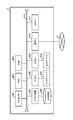
- FIG. 22 shows a functional block configuration example of the server device 2 in another system.
- the server device 2 includes a communication unit 21, a storage unit 23, a DB access unit 24, and a control unit 25.
- the control unit 25 includes a recognition determination unit 251, a movement determination unit 252, a coordinate calculation unit 253, and an image generation unit 254.
- the communication unit 21, the storage unit 23, and the DB access unit 24 perform the same processing as the server device 2 illustrated in FIG.
- the control unit 25 performs display control of the image model based on the information received from the terminal device 1 shown in FIG.
- the recognition determination unit 251, the movement determination unit 252, the coordinate calculation unit 253, and the image generation unit 254 perform the same processing as the recognition determination unit 131, movement determination unit 132, coordinate calculation unit 133, and image generation unit 134, respectively.
- FIG. 23 shows a program configuration example of the server device 2 in another system.
- the hardware (HW) 601 is controlled by an operating system (OS) 602 that has received processing requests from the application program (AP) 606 and middleware (MW) 603 and 605.
- the hardware 601, the operating system 602, and the middleware 603 are the same as those shown in FIG. 7B.
- the middleware 605 is different from the middleware 603 illustrated in FIGS. 7B and 23, and causes the hardware 601 to realize the functions of, for example, the recognition determination unit 251, the movement determination unit 252, the coordinate calculation unit 253, and the image generation unit 254.
- the application program 606 includes a function for providing a scenario to the operator, and includes a function for calling up display control of the image model in accordance with an instruction from the operator.
- the server apparatus 2 activates the middleware 605 and performs display control based on the flow of FIG.
- a projection image to be displayed is generated on the terminal device 1 based on the captured image acquired by the acquisition unit 11, and the generated projection image is It is displayed on the display unit 12 of the terminal device 1.
- the terminal device 1 shown in FIG. 21 and the server device 2 shown in FIG. 23 are used, the projection image is generated by the server device 2, and the projection image is displayed by at least one of the terminal device 1 and the server device 2.
- the terminal device 1 shown in FIG. 21 and the server device 2 shown in FIG. 23 are used, the projection image is generated by the server device 2, and the projection image is displayed by at least one of the terminal device 1 and the server device 2.
Landscapes
- Engineering & Computer Science (AREA)
- Theoretical Computer Science (AREA)
- Physics & Mathematics (AREA)
- General Physics & Mathematics (AREA)
- General Engineering & Computer Science (AREA)
- Computer Hardware Design (AREA)
- Human Computer Interaction (AREA)
- Software Systems (AREA)
- Computer Graphics (AREA)
- Multimedia (AREA)
- Computer Vision & Pattern Recognition (AREA)
- Controls And Circuits For Display Device (AREA)
- Processing Or Creating Images (AREA)
Abstract
An objective of the present invention is, in one aspect, to prevent terminating a display of a projected image despite it being possible to display a projected image in conformity with a captured image. According to one mode, a display control program executes a process on a computer which: acquires a captured image by an image capture element; acquires a movement quantity of the image capture element; commences a display control of an image model which is adjusted according to a location relation between a reference object and the captured image, if an image of the reference object is recognized within the captured image which is acquired from the image capture element, and sustains the display control if the reference object is recognized from within the captured image which is acquired from the image capture element; and if, after the reference object is recognized, the reference object is not recognized from within the captured image which is acquired from the image capture element, and the movement quantity is less than the prescribed quantity, sustains the display control.
Description
本発明は、表示制御技術に関する。
The present invention relates to display control technology.
撮像素子により取得された撮像画像を表示する表示領域内に、画像モデルを投影させて得られる画像(投影画像)を撮像画像と整合させて表示させる技術がある。撮像画像と投影画像とが整合した表示は、撮像画像中に含まれる基準物の像の位置、サイズ及び向きなどに応じて、投影画像の表示領域内の位置、サイズ及び向きなどが調整されることにより行なわれる。
There is a technique for displaying an image (projected image) obtained by projecting an image model in alignment with a captured image in a display area for displaying a captured image acquired by an image sensor. In the display in which the captured image and the projected image are matched, the position, size, orientation, and the like in the display area of the projected image are adjusted according to the position, size, orientation, etc. of the reference object included in the captured image. Is done.
投影画像の表示調整に用いられる基準物には、基準物が撮像画像内に映された像により、基準物と撮像素子との相対位置及び相対的な向き(相対角度)とを計測可能な識別体が用いられる。例えば、AR(Augmented Reality:拡張現実感)マーカーと呼ばれる識別体が基準物として用いられる。ARマーカーは、例えば、ARマーカー自体が撮影された撮像画像に基づいて、撮像素子との相対位置及び相対角度を計測可能な模様(パターン)が印刷された印刷物などである。また、ARマーカーには、撮像画像内のARマーカーの像に基づいて、ARマーカーに印刷されたパターンを解析することにより、ARマーカーから情報を取得可能なものもある。
Identification that can measure the relative position and relative orientation (relative angle) between the reference object and the image sensor based on the image of the reference object reflected in the captured image. The body is used. For example, an identifier called an AR (Augmented Reality) marker is used as a reference object. The AR marker is, for example, a printed matter on which a pattern (pattern) capable of measuring a relative position and a relative angle with respect to the imaging element is printed based on a captured image obtained by capturing the AR marker itself. Some AR markers can acquire information from the AR marker by analyzing a pattern printed on the AR marker based on the image of the AR marker in the captured image.
投影画像の表示中に、撮像画像の更新により、基準物と撮像素子との相対位置及び相対角度の少なくとも一方が変化すると、更新された撮像画像と投影画像とが整合しなくなることがある。そのため、基準物と撮像素子との相対位置及び相対角度に応じて、投影画像の再調整が行なわれる。投影画像の再調整において、更新された撮像画像内に基準物の像が含まれない場合には、更新された撮像画像と整合する投影画像の表示位置やサイズが不明となるため、投影画像の表示を終了させる制御が行なわれる。上述のように、撮像画像内に基準物の像が含まれるか否かの判定に応じた投影画像表示の実行制御によって、撮像画像と整合しない恐れのある投影画像の表示を終了させることができる。
When at least one of the relative position and the relative angle between the reference object and the image sensor changes due to the update of the captured image during the display of the projected image, the updated captured image and the projected image may not match. Therefore, the read image is readjusted according to the relative position and relative angle between the reference object and the image sensor. In the readjustment of the projected image, if the reference image is not included in the updated captured image, the display position and size of the projected image that matches the updated captured image are unknown, Control to end the display is performed. As described above, the display of the projected image that may not match the captured image can be terminated by the execution control of the projected image display according to the determination whether the image of the reference object is included in the captured image. .
一方で、投影画像の再描画に関して、投影画像を表示領域に表示した状態で端末装置に設けられた方位センサの値が所定値以上となった場合にのみ、投影画像の再描画を行なう技術がある(特許文献1~3参照)。
On the other hand, regarding redrawing of a projected image, there is a technique for redrawing a projected image only when the value of an azimuth sensor provided in the terminal device is equal to or greater than a predetermined value while the projected image is displayed in the display area. (See Patent Documents 1 to 3).
しかしながら、撮影範囲が変わらない場合であっても、撮像素子と基準物との間に障害物が入り込むと、基準物が障害物の陰に隠れるため、撮影情報に基準物の像が含まれなくなる。そのような場合に基準物の非認識に基づいて投影画像の表示が終了されると、撮像画像と整合する投影画像の表示が可能であるにも関わらず、投影画像の表示が終了されてしまうこととなる。
However, even if the shooting range does not change, if an obstacle enters between the image sensor and the reference object, the reference object is hidden behind the obstacle, so the image of the reference object is not included in the shooting information. . In such a case, if the display of the projection image is terminated based on the non-recognition of the reference object, the display of the projection image is terminated even though the projection image that matches the captured image can be displayed. It will be.
本開示の一側面においては、撮像画像と整合する投影画像が表示可能であるにも関わらず、投影画像の表示を終了してしまうことを抑制することを目的とする。
An object of one aspect of the present disclosure is to prevent the display of a projection image from being terminated even though a projection image that matches a captured image can be displayed.
一態様によれば、表示制御プログラムが、コンピュータに、 撮像素子から撮像画像を取得するとともに、前記撮像素子の動き量を取得し、前記撮像素子から取得した撮像画像内から基準物の像を認識した場合に、前記基準物と前記撮像素子との位置関係に応じて調整された画像モデルの表示制御を開始するとともに、前記撮像素子から取得した撮像画像内より前記基準物が認識されている場合は前記表示制御を継続し、前記基準物を認識した後、前記撮像素子から取得した撮像画像内より前記基準物が認識されず、かつ、前記動き量が前記所定量未満である場合に、前記表示制御を継続する、処理を実行させる。
According to one aspect, the display control program acquires a captured image from the image sensor to the computer, acquires a movement amount of the image sensor, and recognizes an image of the reference object from the captured image acquired from the image sensor. In this case, display control of the image model adjusted according to the positional relationship between the reference object and the image sensor is started, and the reference object is recognized from within the captured image acquired from the image sensor. Continues the display control, and after recognizing the reference object, the reference object is not recognized from within the captured image acquired from the image sensor, and the movement amount is less than the predetermined amount, The display control is continued and the process is executed.
一態様によれば、コンピュータに、撮像素子により撮像画像を取得するとともに、前記撮像素子の動き量を取得し、前記撮像素子から取得した撮像画像内より基準物の像を認識した場合に、前記基準物と前記撮像素子との位置関係に応じて調整された画像モデルの表示制御を開始するとともに、前記撮像素子から取得した撮像画像内より前記基準物が認識されている場合は前記表示制御を継続し、前記基準物を認識した後、前記撮像素子から取得した撮像画像内より前記基準物が認識されず、かつ、前記動き量が前記所定量未満である場合に、前記表示制御を継続する、処理を実行させることを特徴とする表示制御方法が用いられる。
According to one aspect, when the captured image is acquired by the image sensor in the computer, the amount of movement of the image sensor is acquired, and the image of the reference object is recognized from within the captured image acquired from the image sensor, the Display control of the image model adjusted according to the positional relationship between the reference object and the image sensor is started, and the display control is performed when the reference object is recognized from within the captured image acquired from the image sensor. Continuously, after recognizing the reference object, the display control is continued when the reference object is not recognized from the captured image acquired from the image sensor and the amount of movement is less than the predetermined amount. A display control method characterized by causing the processing to be executed is used.
一態様によれば、表示制御装置は、撮像部と、前記撮像部の動き量を計測するセンサ部と、前記撮像部から撮像画像を取得するとともに、前記センサ部から前記動き量を取得する取得部と、前記撮像部から取得した撮像画像内より基準物の像を認識した場合に、前記基準物と前記撮像素子との位置関係に応じて調整された画像モデルの表示制御を開始するとともに、前記撮像部から取得した撮像画像内より前記基準物が認識されている場合は前記表示制御を継続し、また、前記基準物を認識した後、前記撮像部から取得した撮像画像内より前記基準物が認識されず、かつ、前記動き量が前記所定量未満である場合に、前記表示制御を継続する制御部と、を含む。
According to one aspect, the display control apparatus acquires an image capturing unit, a sensor unit that measures a motion amount of the image capturing unit, a captured image from the image capturing unit, and acquires the motion amount from the sensor unit. And when starting the display control of the image model adjusted according to the positional relationship between the reference object and the image sensor when the image of the reference object is recognized from within the captured image acquired from the imaging unit. When the reference object is recognized from within the captured image acquired from the imaging unit, the display control is continued, and after the reference object is recognized, the reference object from within the captured image acquired from the imaging unit. And a control unit that continues the display control when the amount of movement is less than the predetermined amount.
一側面においては、撮像画像と整合する投影画像が表示可能であるにも関わらず、投影画像の表示を終了してしまうことを抑制することができる。
In one aspect, it is possible to prevent the display of the projection image from being terminated even though the projection image that matches the captured image can be displayed.
本発明の実施形態について、図面を用いて説明する。
Embodiments of the present invention will be described with reference to the drawings.
カメラなどから得られる撮像画像をリアルタイムに表示させる表示デバイスに、撮像画像と整合させて投影画像を重畳表示させる際に、ARマーカーなどのマーカーが基準物として用いられる。マーカーは、画像を撮影する撮像素子に対する相対位置及び相対角度が、撮像画像内に映るマーカー自体の像に基づいて算出可能な識別体である。投影画像は、例えば、マーカーからの位置関係が定義された画像モデルを、マーカーの相対位置及び相対角度に基づいて投影角度やサイズが調整されることで得られる。画像モデルは、事前に形状と表面の模様(パターン)が定義されていても良いし、撮像画像を基に加工されたものでもよい。また、画像モデル自体は、1次元モデル、2次元モデル及び3次元モデルを含む。例えば、モデル自体が、1次元座標や2次元座標で定義されていても、定義されていない方向に定数の座標を与えることで、3次元の座標として表現することとしてもよい。投影画像の表示は、撮像画像を表示する表示デバイスだけでなく、例えば、透過型ディスプレイに対しても行なわれる。透過型ディスプレイに投影画像が表示される場合には、例えば、透過型ディスプレイを介して視認される像と整合するように調整された投影画像が表示される。
A marker such as an AR marker is used as a reference object when a projected image is superimposed and displayed on a display device that displays a captured image obtained from a camera or the like in real time. The marker is an identifier that can calculate a relative position and a relative angle with respect to an image sensor that captures an image based on an image of the marker itself that appears in the captured image. The projection image is obtained, for example, by adjusting the projection angle and size of an image model in which the positional relationship from the marker is defined based on the relative position and relative angle of the marker. The image model may have a shape and a surface pattern (pattern) defined in advance, or may be processed based on a captured image. The image model itself includes a one-dimensional model, a two-dimensional model, and a three-dimensional model. For example, even if the model itself is defined by one-dimensional coordinates or two-dimensional coordinates, it may be expressed as three-dimensional coordinates by giving constant coordinates in directions not defined. The projection image is displayed not only on the display device that displays the captured image but also on, for example, a transmissive display. When the projection image is displayed on the transmissive display, for example, the projection image adjusted to match the image viewed through the transmissive display is displayed.
図1A乃至Cのそれぞれは、マーカーと投影画像との関係の説明図である。フレームFは、撮像素子により撮影される範囲を示し、フレームFの内部は、撮像画像及び投影画像を表示させる表示画面の例を示す。図1A乃至Cにおいては、実際に表示される内容が実線で表記され、実際に表示されない内容は点線で表記されている(矢印は除く)。
1A to 1C are explanatory diagrams of the relationship between a marker and a projected image. A frame F indicates a range captured by the image sensor, and an inside of the frame F indicates an example of a display screen that displays a captured image and a projected image. In FIGS. 1A to 1C, the content that is actually displayed is indicated by a solid line, and the content that is not actually displayed is indicated by a dotted line (except for an arrow).
図1Aは、マーカーが認識された場合の投影画像の表示例を示す。図1Aに示す例においては、マーカーM1の像が撮像画像内に含まれる。また、投影画像PI1は、マーカーM1を基準として定義される画像モデルが、マーカーの相対位置及び相対角度とに基づいて調整されて生成される。画像モデルの定義には、マーカーに対してどの位置に存在するか(図1における矢印に相当する)、どのような形状をしているか(図1では立方体が例示されている)、などの指定が含まれる。
FIG. 1A shows a display example of a projected image when a marker is recognized. In the example illustrated in FIG. 1A, an image of the marker M1 is included in the captured image. The projected image PI1 is generated by adjusting an image model defined with the marker M1 as a reference based on the relative position and relative angle of the marker. In the definition of the image model, a position such as where the marker exists (corresponding to an arrow in FIG. 1), what shape it is in (a cube is illustrated in FIG. 1), etc. are specified. Is included.
図1Aに例示されるマーカーM1は、撮像素子とほぼ並行な向きを向いており、さらに、マーカーM1に対してどの位置に画像モデルが存在するかを示す矢印がほぼマーカーM1の面上に存在する。そのため、マーカーM1と投影画像PI1とのそれぞれの奥行きが、ほぼ同じ程度に表示される。投影画像PI2は、投影画像PI1と同様の定義がマーカーM2を基準として行なわれた画像モデルの投影画像である。図1Aにおいて、マーカーM2は、マーカーM1よりも浅い角度で映り込んでいる。そのため、マーカーM2を基準とする投影画像PI2は、マーカーM2と異なる奥行きで表示される。マーカーM1及びマーカーM2を用いて説明したように、マーカーの像(映り方)に応じて、そのマーカーを基準として定義される投影画像の表示位置、サイズ及び向きが調整される。
The marker M1 illustrated in FIG. 1A is oriented substantially parallel to the image sensor, and an arrow indicating where the image model is located with respect to the marker M1 is substantially on the surface of the marker M1. To do. For this reason, the depths of the marker M1 and the projected image PI1 are displayed to be approximately the same. The projected image PI2 is a projected image of an image model in which the same definition as the projected image PI1 is made with reference to the marker M2. In FIG. 1A, the marker M2 is reflected at a shallower angle than the marker M1. Therefore, the projected image PI2 with the marker M2 as a reference is displayed with a depth different from that of the marker M2. As described with reference to the marker M1 and the marker M2, the display position, size, and orientation of the projection image defined with the marker as a reference are adjusted according to the marker image (how it is projected).
図1Bは、マーカーがフレームアウトした場合の撮像画像の例を示す。図1Bの例においては、マーカーM3の像がフレームF内に含まれない。そのため、マーカーM3を基準に定義される画像モデルがあったとしても、その画像モデルに対応する投影画像(投影画像PI3)の表示は行なわれない。すなわち、マーカーの像がフレームアウトすると、表示の基準が不明になるため、投影画像の表示が中断される。図1Bにおいて、投影画像PI3を点線で示しているのは、マーカーM3を基準に定義される3Dモデルが存在するが、マーカーM3が認識されないために表示されないことを便宜的に示すためである。
FIG. 1B shows an example of a captured image when the marker is out of frame. In the example of FIG. 1B, the image of the marker M3 is not included in the frame F. For this reason, even if there is an image model defined with reference to the marker M3, the projection image (projection image PI3) corresponding to the image model is not displayed. That is, when the marker image is out of frame, the display reference is unclear, and the display of the projected image is interrupted. In FIG. 1B, the projected image PI3 is indicated by a dotted line in order to conveniently indicate that there is a 3D model defined based on the marker M3, but the marker M3 is not displayed because it is not recognized.
例えば、あるマーカーを基準とする投影画像を表示させた後に、別のマーカーを基準とする投影画像を表示させる場合には、カメラが別の撮影対象に向けられるため、先に基準としていたマーカーのフレームアウトが生じうる。先に基準としていたマーカーのフレームアウトと、新しく基準となるマーカーのフレームインによって、投影画像表示の基準の切り換えが行なわれる。また、例えば、マーカーを基準とする投影画像の表示を終了させる場合には、カメラを撮影対象(投影画像表示の基準となるマーカーや投影画像など)に向け続ける必要がなくなる。その際には、操作者が別の操作(重畳表示の終了操作や端末に対する入力操作など)を行なうなどによりマーカーがフレームアウトすることとなり、操作者の意図に沿ったタイミングにおいて投影画像表示が終了となる。
For example, when displaying a projected image based on a certain marker and then displaying a projected image based on another marker, the camera is directed to another imaging target. Frame out can occur. The projection image display reference is switched by the frame out of the marker previously used as a reference and the frame in of a marker as a new reference. Further, for example, when the display of the projection image based on the marker is terminated, it is not necessary to keep the camera directed toward the photographing target (a marker or a projection image serving as a reference for the projection image display). In that case, the marker will be out of frame when the operator performs another operation (such as an operation to end the superimposed display or an input operation to the terminal), and the projection image display ends at a timing in line with the operator's intention. It becomes.
図1Cは、障害物(図1Cの例では操作者の手)により、マーカーが認識できない場合の撮像画像の例を示す。図1Cにおいて、マーカーM4はフレームF内に収まっているが、障害物の存在により、マーカーM4の像が識別できない。そのため、マーカーM4を基準とする投影画像PI4の表示が中断されてしまう。障害物による投影画像表示の中断は、別の撮影対象へのフレームの移動や、操作者の別の操作への移行などの操作者の意図に沿ったフレームアウトによる中断と異なり、操作者が継続して投影画像を表示させようとした場合にも起こり得る。
FIG. 1C shows an example of a captured image when a marker cannot be recognized due to an obstacle (in the example of FIG. 1C, an operator's hand). In FIG. 1C, the marker M4 is within the frame F, but the image of the marker M4 cannot be identified due to the presence of an obstacle. Therefore, the display of the projection image PI4 with the marker M4 as a reference is interrupted. The interruption of the projected image display due to an obstacle is different from the interruption due to the out-of-frame according to the operator's intention such as moving the frame to another shooting target or shifting the operator to another operation. This can also occur when trying to display a projected image.
操作者に投影画像表示を継続させる意図がある場合に、障害物により意図に沿わずに投影画像表示が中断されることとなれば、操作性を損なう要因となる。さらに、投影画像の表示を用いたアプリケーションプログラムに、複数の投影画像を順序立てて表示させるシナリオが存在する場合も想定される。そのようなアプリケーションプログラムの動作中に投影画像の表示が中断された場合には、例えば、シナリオが開始地点に戻ることとなる。もしくは、アプリケーションプログラム自体に、投影画像の表示が中断された場合のシナリオ復帰の仕組みが設けられることとなる。このような事態に対して、マーカーの像が撮像画像内に含まれないことの判定のみでなく、さらに撮影素子そのものが動いたことの検知が行なわれた場合にのみ、投影画像表示の中断が行われることで、操作者が意図しない投影画像表示の中断が抑制される。
If the operator intends to continue displaying the projected image, if the projected image display is interrupted without obeying the intention due to an obstacle, the operability is impaired. Further, there may be a scenario in which a plurality of projection images are displayed in order in an application program that uses display of projection images. When the display of the projection image is interrupted during the operation of such an application program, for example, the scenario returns to the start point. Alternatively, the application program itself is provided with a scenario recovery mechanism when the display of the projected image is interrupted. For such a situation, not only the determination that the marker image is not included in the captured image, but also that the projection image display is interrupted only when it is detected that the imaging element itself has moved. By doing so, interruption of projection image display unintended by the operator is suppressed.
図2は、本実施形態のシステム構成を示す。図2に示すシステムは、端末装置1、サーバ装置2、記憶装置3、ネットワーク4及び基地局5を含む。端末装置1とサーバ装置2とは、有線または無線のいずれか少なくとも一方の通信方法により通信可能である。サーバ装置2は、記憶装置3に含まれるデータベース3aにアクセス可能である。
FIG. 2 shows the system configuration of this embodiment. The system shown in FIG. 2 includes a terminal device 1, a server device 2, a storage device 3, a network 4, and a base station 5. The terminal device 1 and the server device 2 can communicate with each other by at least one of a wired or wireless communication method. The server device 2 can access the database 3 a included in the storage device 3.
図3は、端末装置1の機能ブロックの構成を示す。端末装置1は、取得部11、表示部12、制御部13、記憶部14および通信部15を含む。取得部11は、端末装置1に備えられたセンサにより計測された情報を取得する。取得部11により取得される情報は、例えば、撮像素子により撮影された画像や、端末装置1の動き量を示す情報(加速度・角速度センサにより計測される値など)である。例えば、取得部11は、設定された時間間隔で情報を取得する。表示部12は、制御部13の制御に応じて画像を表示させる。例えば、図1A乃至Cに示す画面のように、取得部11が取得した撮像画像や、投影画像の表示を行なう。制御部13は、取得部11が取得した情報および通信部15を介して取得した情報に応じて処理を行ない、表示部12及び通信部15を制御する。記憶部14は、制御部13に処理に用いられる情報を記憶する。例えば、後述の認識管理テーブルT1、マーカー座標テーブルT2、座標テーブルT3、移動量テーブルT4及び図17に示す投影画像管理テーブルT5などを記憶する。通信部15は、制御部13の制御に応じて、サーバ装置2などの装置との通信を行なう。制御部13は、3Dモデルの定義情報を記憶部12から取得するか、もしくは通信部15の通信によりサーバ装置2から取得する。すなわち、端末装置1が単体で動作する態様もある一方で、端末装置1とサーバ装置2とが連携して処理を行なう態様もあり得る。
FIG. 3 shows a functional block configuration of the terminal device 1. The terminal device 1 includes an acquisition unit 11, a display unit 12, a control unit 13, a storage unit 14, and a communication unit 15. The acquisition unit 11 acquires information measured by a sensor provided in the terminal device 1. The information acquired by the acquisition unit 11 is, for example, an image captured by the image sensor or information indicating the amount of movement of the terminal device 1 (such as a value measured by an acceleration / angular velocity sensor). For example, the acquisition unit 11 acquires information at a set time interval. The display unit 12 displays an image under the control of the control unit 13. For example, as in the screens shown in FIGS. 1A to 1C, the captured image acquired by the acquisition unit 11 and the projection image are displayed. The control unit 13 performs processing according to the information acquired by the acquisition unit 11 and the information acquired via the communication unit 15, and controls the display unit 12 and the communication unit 15. The storage unit 14 stores information used for processing in the control unit 13. For example, a recognition management table T1, a marker coordinate table T2, a coordinate table T3, a movement amount table T4, a projection image management table T5 shown in FIG. The communication unit 15 communicates with a device such as the server device 2 under the control of the control unit 13. The control unit 13 acquires the definition information of the 3D model from the storage unit 12 or acquires it from the server device 2 through communication of the communication unit 15. That is, while there is a mode in which the terminal device 1 operates alone, there may be a mode in which the terminal device 1 and the server device 2 perform processing in cooperation.
制御部13は、認識判定部131、移動判定部132、座標算出部133及び画像生成部134を含む。
The control unit 13 includes a recognition determination unit 131, a movement determination unit 132, a coordinate calculation unit 133, and an image generation unit 134.
認識判定部131は、取得部11が取得した情報に応じて、マーカーを認識しているか否か判断する。認識判定部131は、撮像画像内にマーカーの像が含まれるか否かの判断と、端末装置1が動いたか否かの判断とを行なう。例えば、認識判定部131は、撮像画像内にマーカーの像が含まれるか否かの判断を定期的に行ない、認識状態にあったマーカーの像が撮像画像に像が含まれなくなった場合に、端末装置1本体の移動量に応じて、そのマーカーの認識状態を解除するか否かの判定を行なう。
The recognition determination unit 131 determines whether the marker is recognized according to the information acquired by the acquisition unit 11. The recognition determination unit 131 determines whether or not the marker image is included in the captured image and whether or not the terminal device 1 has moved. For example, the recognition determination unit 131 periodically determines whether or not a marker image is included in the captured image, and when the marker image in the recognition state no longer includes the image in the captured image, It is determined whether or not to cancel the recognition state of the marker according to the movement amount of the terminal device 1 main body.
移動判定部132は、認識判定部131の呼び出しに応じて端末装置1の移動量を算出する。認識判定部131は、移動判定部132が算出した移動量に応じて、端末装置1本体が動いたか否かの判定を行なう。移動判定部132による移動量の算出は、例えば、取得部11が取得した加速度センサや角速度センサの計測値に基づいて算出される。もしくは、移動判定部132が、マーカーの位置座標の履歴に基づいて移動予測量を算出し、認識判定部131が移動予測量に基づいて、マーカーの認識状態を解除するか否かの判断を行なってもよい。
The movement determination unit 132 calculates the movement amount of the terminal device 1 in response to the call of the recognition determination unit 131. The recognition determination unit 131 determines whether or not the main body of the terminal device 1 has moved according to the movement amount calculated by the movement determination unit 132. The movement amount calculation by the movement determination unit 132 is calculated based on, for example, the measurement values of the acceleration sensor and the angular velocity sensor acquired by the acquisition unit 11. Alternatively, the movement determination unit 132 calculates a movement prediction amount based on the history of the marker position coordinates, and the recognition determination unit 131 determines whether to cancel the marker recognition state based on the movement prediction amount. May be.
座標算出部133は、認識判定部131の呼び出しに応じて、撮像画像に含まれるマーカーの像に基づき、マーカーと撮像素子との相対位置及び相対角度を算出する処理を行なう。さらに、座標算出部133は、画像生成部134の呼び出しに応じて、3Dモデルに含まれる各頂点の座標変換を行なう。具体的には、座標算出部133は、マーカーを基準とする座標系で定義された座標から、3Dモデルを画面に表示させた際の表示画面中の位置を示す座標に変換する。この座標変換は、先に計算したマーカーの相対位置及び相対角度に基づいて行なわれる。
The coordinate calculation unit 133 performs a process of calculating the relative position and the relative angle between the marker and the image sensor based on the marker image included in the captured image in response to the call of the recognition determination unit 131. Furthermore, the coordinate calculation unit 133 performs coordinate conversion of each vertex included in the 3D model in response to the call of the image generation unit 134. Specifically, the coordinate calculation unit 133 converts coordinates defined in a coordinate system with the marker as a reference into coordinates indicating a position in the display screen when the 3D model is displayed on the screen. This coordinate conversion is performed based on the previously calculated relative position and relative angle of the marker.
画像生成部134は、認識判定部131により認識されているマーカーに関連付けられた3Dモデルについて、座標算出部133により変換された各頂点の座標と、3Dモデルの定義とに基づいて、3Dモデルに対応した投影画像を生成する。制御部13は、画像生成部134により生成された画像を表示部12に表示させる制御を行なう。
The image generation unit 134 converts the 3D model associated with the marker recognized by the recognition determination unit 131 into a 3D model based on the coordinates of each vertex converted by the coordinate calculation unit 133 and the definition of the 3D model. A corresponding projection image is generated. The control unit 13 performs control to display the image generated by the image generation unit 134 on the display unit 12.
図4は端末装置1のハードウェア構成を示す。図3に示す各機能ブロックは、例えば、図4に示すハードウェア構成により実現される。端末装置1は、例えば、プロセッサ301、RAM(Random Access Memory)302、ROM(Read Only Memory)303、ドライブ装置304、記憶媒体305、入力インターフェース(入力I/F)306、入力デバイス307、出力インターフェース(出力I/F)308、出力デバイス309、通信インターフェース(通信I/F)310、カメラモジュール311、加速度センサ312、角速度センサ313およびバス314などを含む。それぞれのハードウェアはバス314を介して接続されている。
FIG. 4 shows the hardware configuration of the terminal device 1. Each functional block shown in FIG. 3 is realized by, for example, the hardware configuration shown in FIG. The terminal device 1 includes, for example, a processor 301, a RAM (Random Access Memory) 302, a ROM (Read Only Memory) 303, a drive device 304, a storage medium 305, an input interface (input I / F) 306, an input device 307, and an output interface. (Output I / F) 308, output device 309, communication interface (communication I / F) 310, camera module 311, acceleration sensor 312, angular velocity sensor 313, bus 314, and the like. Each piece of hardware is connected via a bus 314.
通信インターフェース310はネットワーク4を介した通信の制御を行なう。通信インターフェース310が制御する通信は、ネットワーク4に基地局5を介してアクセスする態様もあり得る。入力インターフェース306は、入力デバイス307と接続されており、入力デバイス307から受信した入力信号をプロセッサ301に伝達する。出力インターフェース308は、出力デバイス309と接続されており、出力デバイス309に、プロセッサ301の指示に応じた出力を実行させる。入力デバイス307は、操作に応じて入力信号を送信する装置である。入力信号は、例えば、キーボードや端末装置1の本体に取り付けられたボタンなどのキー装置や、マウスやタッチパネルなどのポインティングデバイスである。出力デバイス309は、端末装置1の制御に応じて情報を出力する装置である。出力デバイス309は、例えば、ディスプレイなどの画像出力装置(表示デバイス)や、スピーカーなどの音声出力装置などである。前述の通り、表示デバイスには、透過型ディスプレイが用いられてもよい。また、例えば、タッチスクリーンなどの入出力装置が、入力デバイス307及び出力デバイス309として用いられる。また、入力デバイス307及び出力デバイス309は、端末装置1に含まれず、例えば、端末装置1に外部から接続する装置であってもよい。
The communication interface 310 controls communication via the network 4. The communication controlled by the communication interface 310 may have a mode in which the network 4 is accessed via the base station 5. The input interface 306 is connected to the input device 307 and transmits an input signal received from the input device 307 to the processor 301. The output interface 308 is connected to the output device 309 and causes the output device 309 to execute output in accordance with an instruction from the processor 301. The input device 307 is a device that transmits an input signal according to an operation. The input signal is, for example, a keyboard or a key device such as a button attached to the main body of the terminal device 1 or a pointing device such as a mouse or a touch panel. The output device 309 is a device that outputs information according to the control of the terminal device 1. The output device 309 is, for example, an image output device (display device) such as a display, or an audio output device such as a speaker. As described above, a transmissive display may be used as the display device. For example, an input / output device such as a touch screen is used as the input device 307 and the output device 309. Further, the input device 307 and the output device 309 are not included in the terminal device 1 and may be devices connected to the terminal device 1 from the outside, for example.
RAM302は読み書き可能なメモリ装置であって、例えば、SRAM(Static RAM)やDRAM(Dynamic RAM)などの半導体メモリ、またはRAM以外にもフラッシュメモリなどが用いられてもよい。ROM303は、PROM(Programmable ROM)なども含む。ドライブ装置304は、記憶媒体305に記録された情報の読み出しか書き込みかの少なくともいずれか一方を行なう装置である。記憶媒体305は、ドライブ装置304によって書き込まれた情報を記憶する。記憶媒体305は、例えば、ハードディスク、CD(Compact Disc)、DVD(Digital Versatile Disc)、ブルーレイディスクなどの記憶媒体である。また、例えば、コンピュータ1は、複数種類の記憶媒体それぞれについて、ドライブ装置304及び記憶媒体305を設ける。
The RAM 302 is a readable / writable memory device. For example, a semiconductor memory such as SRAM (Static RAM) or DRAM (Dynamic RAM), or a flash memory other than the RAM may be used. The ROM 303 includes a PROM (Programmable ROM). The drive device 304 is a device that performs at least one of reading and writing of information recorded in the storage medium 305. The storage medium 305 stores information written by the drive device 304. The storage medium 305 is, for example, a storage medium such as a hard disk, a CD (Compact Disc), a DVD (Digital Versatile Disc), or a Blu-ray disc. Further, for example, the computer 1 includes a drive device 304 and a storage medium 305 for each of a plurality of types of storage media.
カメラモジュール311は、撮像素子(イメージセンサ)を含み、例えば、撮像素子が計測した値を読み出し、カメラモジュール311に含まれる入力画像用の画像バッファに書き込む。加速度センサ312は、加速度センサ312に対して作用する加速度を計測する。角速度センサ313は、角速度センサ313による動作の角速度を計測する。
The camera module 311 includes an image sensor (image sensor). For example, the camera module 311 reads a value measured by the image sensor and writes it in an image buffer for an input image included in the camera module 311. The acceleration sensor 312 measures acceleration acting on the acceleration sensor 312. The angular velocity sensor 313 measures the angular velocity of the operation by the angular velocity sensor 313.
プロセッサ301は、ROM303や記憶媒体305に記憶されたプログラム(例えば図7Aおよび図22などに例示するプログラム)をRAM302に読み出し、読み出されたプログラムの手順に従って制御部13の処理を行なう。その際にRAM302はプロセッサ301のワークエリアとして用いられる。記憶部14の機能は、ROM303および記憶媒体305がプログラムファイルやデータファイルを記憶すること、もしくは、RAM302がプロセッサ301のワークエリアとして用いられることによって実現される。
The processor 301 reads a program (for example, a program illustrated in FIG. 7A and FIG. 22) stored in the ROM 303 and the storage medium 305 to the RAM 302, and performs processing of the control unit 13 according to the read program procedure. At that time, the RAM 302 is used as a work area of the processor 301. The function of the storage unit 14 is realized by the ROM 303 and the storage medium 305 storing program files and data files, or by using the RAM 302 as a work area of the processor 301.
また、カメラモジュール311が画像データを生成し、生成された画像データをプロセッサ301が取得すること、ならびに加速度センサ312及び角速度センサ313が計測した値をプロセッサ301が取得することにより、取得部11の機能が実現される。カメラモジュール311からプロセッサ301に引き渡される画像データは、例えば、カメラモジュール311が備える入力画像用のバッファに蓄積され、プロセッサ301は、入力画像用のバッファから画像データを読み出す。
In addition, the camera module 311 generates image data, the processor 301 acquires the generated image data, and the processor 301 acquires values measured by the acceleration sensor 312 and the angular velocity sensor 313, whereby the acquisition unit 11 Function is realized. For example, the image data delivered from the camera module 311 to the processor 301 is accumulated in an input image buffer provided in the camera module 311, and the processor 301 reads the image data from the input image buffer.
さらに、プロセッサ301が、出力用の画像データを生成し、生成した画像データが出力デバイス309である表示デバイスに表示されることにより、表示部12の機能が実現される。プロセッサ301が生成した出力用の画像データは、出力インターフェース308に備えられた出力画像用のバッファに書き込まれ、表示デバイスは出力画像用のバッファから画像データを読み出し、読み出した画像データを表示する。
Further, the processor 301 generates image data for output, and the generated image data is displayed on the display device that is the output device 309, thereby realizing the function of the display unit 12. The output image data generated by the processor 301 is written in an output image buffer provided in the output interface 308, and the display device reads the image data from the output image buffer and displays the read image data.
図5は、サーバ装置2の機能ブロックの構成例を示す。サーバ装置2は、通信部21、制御部22、記憶部23及びDBアクセス部24を含む。通信部21は、制御部22の制御に応じて端末装置1と通信を行なう。制御部22は、通信部21の通信により端末装置1から情報の取得要求を受けた場合に、記憶部23から情報を読み出して、読み出した情報を通信部21に端末装置1に送信させる。もしくは、制御部22は、DBアクセス部24が記憶装置3に含まれるデータベース3aから情報を読み出し、読み出した情報を通信部21に端末装置1に送信させる。端末装置1から取得を要求される情報は、例えば、マーカーに対応付けられた3Dモデルの定義情報などである。記憶部23は、3Dモデルの定義情報などを記憶し、DBアクセス部24は、制御部22の制御に応じて記憶装置3に含まれるデータベース3aにアクセスする。
FIG. 5 shows a functional block configuration example of the server apparatus 2. The server device 2 includes a communication unit 21, a control unit 22, a storage unit 23, and a DB access unit 24. The communication unit 21 communicates with the terminal device 1 under the control of the control unit 22. When receiving an information acquisition request from the terminal device 1 through communication of the communication unit 21, the control unit 22 reads information from the storage unit 23 and causes the communication unit 21 to transmit the read information to the terminal device 1. Alternatively, in the control unit 22, the DB access unit 24 reads information from the database 3 a included in the storage device 3, and causes the communication unit 21 to transmit the read information to the terminal device 1. The information requested to be acquired from the terminal device 1 is, for example, 3D model definition information associated with the marker. The storage unit 23 stores 3D model definition information and the like, and the DB access unit 24 accesses the database 3 a included in the storage device 3 under the control of the control unit 22.
図6はサーバ装置2のハードウェア構成を示す。図5に示す各機能ブロックは、例えば、図6に示すハードウェア構成により実現される。サーバ装置2は、例えば、プロセッサ401、RAM(Random Access Memory)402、ROM(Read Only Memory)403、ドライブ装置404、記憶媒体405、入力インターフェース(入力I/F)406、入力デバイス407、出力インターフェース(出力I/F)408、出力デバイス409、通信インターフェース(通信I/F)410、SAN(Storage Area Network)インターフェース(SAN I/F)411及びバス412などを含む。それぞれのハードウェアはバス412を介して接続されている。
FIG. 6 shows the hardware configuration of the server device 2. Each functional block shown in FIG. 5 is realized by, for example, the hardware configuration shown in FIG. The server device 2 includes, for example, a processor 401, a RAM (Random Access Memory) 402, a ROM (Read Only Memory) 403, a drive device 404, a storage medium 405, an input interface (input I / F) 406, an input device 407, and an output interface. (Output I / F) 408, output device 409, communication interface (communication I / F) 410, SAN (Storage Area Network) interface (SAN I / F) 411, bus 412 and the like are included. Each piece of hardware is connected via a bus 412.
通信インターフェース410はネットワーク4を介した通信の制御を行なう。入力インターフェース406は、入力デバイス407と接続されており、入力デバイス407から受信した入力信号をプロセッサ401に伝達する。出力インターフェース408は、出力デバイス409と接続されており、出力デバイス409に、プロセッサ401の指示に応じた出力を実行させる。入力デバイス407は、操作に応じて入力信号を送信する装置である。入力信号は、例えば、キーボードやサーバ装置2の本体に取り付けられたボタンなどのキー装置や、マウスやタッチパネルなどのポインティングデバイスである。出力デバイス409は、サーバ装置2の制御に応じて情報を出力する装置である。出力デバイス409は、例えば、ディスプレイなどの画像出力装置(表示デバイス)や、スピーカーなどの音声出力装置などである。また、例えば、タッチスクリーンなどの入出力装置が、入力デバイス407及び出力デバイス409として用いられる。また、入力デバイス407及び出力デバイス409は、サーバ装置2に含まれず、例えば、サーバ装置2に外部から接続する装置であってもよい。
The communication interface 410 controls communication via the network 4. The input interface 406 is connected to the input device 407 and transmits an input signal received from the input device 407 to the processor 401. The output interface 408 is connected to the output device 409 and causes the output device 409 to execute output in accordance with an instruction from the processor 401. The input device 407 is a device that transmits an input signal according to an operation. The input signal is, for example, a key device such as a keyboard or a button attached to the main body of the server device 2 or a pointing device such as a mouse or a touch panel. The output device 409 is a device that outputs information in accordance with the control of the server device 2. The output device 409 is, for example, an image output device (display device) such as a display, or an audio output device such as a speaker. For example, an input / output device such as a touch screen is used as the input device 407 and the output device 409. Further, the input device 407 and the output device 409 are not included in the server device 2 and may be devices connected to the server device 2 from the outside, for example.
RAM402は読み書き可能なメモリ装置であって、例えば、SRAM(Static RAM)やDRAM(Dynamic RAM)などの半導体メモリ、またはRAM以外にもフラッシュメモリなどが用いられてもよい。ROM403は、PROM(Programmable ROM)なども含む。ドライブ装置404は、記憶媒体405に記録された情報の読み出しか書き込みかの少なくともいずれか一方を行なう装置である。記憶媒体405は、ドライブ装置404によって書き込まれた情報を記憶する。記憶媒体405は、例えば、ハードディスク、CD(Compact Disc)、DVD(Digital Versatile Disc)、ブルーレイディスクなどの記憶媒体である。また、例えば、サーバ装置2は、複数種類の記憶媒体それぞれについて、ドライブ装置404及び記憶媒体405を設ける。
The RAM 402 is a readable / writable memory device. For example, a semiconductor memory such as SRAM (Static RAM) or DRAM (Dynamic RAM), or a flash memory other than the RAM may be used. The ROM 403 includes a PROM (Programmable ROM). The drive device 404 is a device that performs at least one of reading and writing of information recorded on the storage medium 405. The storage medium 405 stores information written by the drive device 404. The storage medium 405 is a storage medium such as a hard disk, a CD (Compact Disc), a DVD (Digital Versatile Disc), or a Blu-ray disc. In addition, for example, the server device 2 includes a drive device 404 and a storage medium 405 for each of a plurality of types of storage media.
プロセッサ401は、ROM403や記憶媒体405に記憶されたプログラム(例えば図7Bまたは図23に例示するプログラム)をRAM402に読み出し、読み出されたプログラムの手順に従って制御部22の処理を行なう。その際にRAM402はプロセッサ401のワークエリアとして用いられる。記憶部23の機能は、ROM403および記憶媒体405がプログラムファイルやデータファイル(投影画像の定義情報(CADデータ)など)を記憶すること、もしくは、RAM402がプロセッサ401のワークエリアとして用いられることによって実現される。また、プロセッサ401の制御に応じてSANインターフェース411が動作することで、データベース3aへのアクセス処理というDBアクセス部24の機能が実現される。
The processor 401 reads a program (for example, the program illustrated in FIG. 7B or FIG. 23) stored in the ROM 403 or the storage medium 405 to the RAM 402, and performs the processing of the control unit 22 according to the read program procedure. At that time, the RAM 402 is used as a work area of the processor 401. The functions of the storage unit 23 are realized by the ROM 403 and the storage medium 405 storing program files and data files (projection image definition information (CAD data) or the like), or the RAM 402 is used as a work area of the processor 401. Is done. Further, the SAN interface 411 operates in accordance with the control of the processor 401, thereby realizing the function of the DB access unit 24 such as access processing to the database 3a.
図7Aは、端末装置1で動作するプログラムの構成例を示す。端末装置1において、ハードウェア群501(図4に示されるハードウェア)の制御を行なうOS(オペレーティング・システム)502が動作する。OS502に従った手順でプロセッサ301が動作して、ハードウェア501の制御・管理が行なわれることにより、アプリケーションプログラム504やミドルウェア503による処理がハードウェア501により実行される。端末装置1において、OS502、ミドルウェア503及びアプリケーションプログラム504などのプログラムが、RAM302に読み出されてプロセッサ301により実行される。また、プロセッサ301がミドルウェア503に基づく処理を行なうことにより、(それらの処理をOS502に基づいてハードウェア501の制御が行なわれ、)取得部11、表示部12、制御部13、記憶部14及び通信部15の機能が実現される。また、ミドルウェア503とアプリケーションプログラム504とは、連動した動作を実行させる別個のプログラムでもよいし、一体のプログラムでもよい。
FIG. 7A shows a configuration example of a program operating on the terminal device 1. In the terminal device 1, an OS (Operating System) 502 that controls a hardware group 501 (hardware shown in FIG. 4) operates. The processor 301 operates in accordance with the procedure in accordance with the OS 502, and the hardware 501 is controlled and managed, whereby the processing by the application program 504 and the middleware 503 is executed by the hardware 501. In the terminal device 1, programs such as the OS 502, middleware 503, and application program 504 are read into the RAM 302 and executed by the processor 301. Further, when the processor 301 performs processing based on the middleware 503 (the hardware 501 is controlled based on the OS 502), the acquisition unit 11, the display unit 12, the control unit 13, the storage unit 14, and The function of the communication unit 15 is realized. Further, the middleware 503 and the application program 504 may be separate programs that execute linked operations or may be integrated programs.
アプリケーションプログラム504には、例えば、ミドルウェア503の投影画像の表示制御機能を用いた処理の手順が示される。例えば、投影画像の表示と、その表示に応じた入力の検知、さらにその入力に応じた投影画像の表示制御など、入力に従った投影画像表示のシナリオが決められてもよい。アプリケーションプログラム504に従った処理により、例えば、後述の投影画像管理テーブルT5において、マーカーIDに関連付けされるモデルの関連付けフラグが変更されてもよい。
In the application program 504, for example, a procedure of processing using the display control function of the projected image of the middleware 503 is shown. For example, a scenario of displaying a projection image, a detection of an input corresponding to the display, and a display control of the projection image corresponding to the input may be determined. By the processing according to the application program 504, for example, the association flag of the model associated with the marker ID may be changed in the projection image management table T5 described later.
図7Bは、サーバ装置2で動作するプログラムの構成例を示す。サーバ装置2において、ハードウェア群601(図6に示されるハードウェア)の制御を行なうOS602が動作する。OS602に従った手順でプロセッサ401が動作して、ハードウェア601の制御・管理が行なわれることにより、アプリケーションプログラム604やミドルウェア603による処理がハードウェア601により実行される。サーバ装置2において、OS602、ミドルウェア603及びアプリケーションプログラム604などのプログラムが、RAM402に読み出されてプロセッサ401により実行される。また、プロセッサ401がミドルウェア403に基づく処理を行なうことにより、(それらの処理をOS602に基づいてハードウェア601の制御が行なわれ、)通信部21、制御部22、記憶部23及びDBアクセス部24の機能が実現される。また、ミドルウェア603とアプリケーションプログラム604とは、連動した動作を実行させる別個のプログラムでもよいし、一体のプログラムでもよい。
FIG. 7B shows a configuration example of a program operating on the server device 2. In the server apparatus 2, an OS 602 that controls a hardware group 601 (hardware shown in FIG. 6) operates. The processor 401 operates in accordance with the procedure in accordance with the OS 602, and the hardware 601 is controlled and managed, whereby the processing by the application program 604 and the middleware 603 is executed by the hardware 601. In the server device 2, programs such as the OS 602, middleware 603, and application program 604 are read into the RAM 402 and executed by the processor 401. Further, when the processor 401 performs processing based on the middleware 403 (the processing of the hardware 601 is performed based on the OS 602), the communication unit 21, the control unit 22, the storage unit 23, and the DB access unit 24. The function is realized. Further, the middleware 603 and the application program 604 may be separate programs that execute linked operations or may be integrated programs.
図8は、端末装置1における表示制御のフローチャートを示す。投影画像の表示機能が呼び出される(S100)と、制御部13が前処理を行なう(S101)。投影画像の表示機能は、例えば、アプリケーションプログラム504の手順に従った処理により呼び出される。例えば、S101の前処理において、制御部13は、加速度・角速度に基づく移動量算出のフローの開始や、認識管理テーブルT1およびマーカー座標テーブルT2の記憶領域の確保、投影画像管理テーブルT5の読出しなどを行なう。さらに、制御部13は、カウンタCT1の値を初期化する。S101の処理の次に、認識判定部131は、取得部11から取得した撮像画像に基づいて、マーカー認識処理を行なう(S102)。S102のマーカー認識処理については、図11に基づいて後述する。マーカー認識処理は、例えば、時間間隔I2で行われる。時間間隔T2は、カメラモジュール311が入力用画像バッファに読み出した画像を書き込む時間間隔T1に対して、例えば、1~数倍の時間間隔である。
FIG. 8 shows a flowchart of display control in the terminal device 1. When the display function of the projected image is called (S100), the control unit 13 performs preprocessing (S101). The projection image display function is called, for example, by processing according to the procedure of the application program 504. For example, in the pre-processing of S101, the control unit 13 starts a movement amount calculation flow based on acceleration / angular velocity, secures storage areas for the recognition management table T1 and the marker coordinate table T2, reads the projection image management table T5, and the like. To do. Further, the control unit 13 initializes the value of the counter CT1. Following the processing of S101, the recognition determination unit 131 performs marker recognition processing based on the captured image acquired from the acquisition unit 11 (S102). The marker recognition process in S102 will be described later with reference to FIG. The marker recognition process is performed, for example, at a time interval I2. The time interval T2 is, for example, one to several times the time interval T1 for writing the image read by the camera module 311 in the input image buffer.
図9Aは、認識管理テーブルT1を示す。認識管理テーブルT1は、認識判定部131により認識されたマーカーの識別情報(マーカーID)、認識されたマーカーの画面内位置を示す座標(Xr,Yr)、および認識結果の格納先を示すポインタを格納する。マーカーIDは、撮像画像内のマーカーの像に対して画像解析を行なうことにより読み出される情報である。マーカーIDは、例えば、備えられるマーカーのそれぞれを一意に特定可能な情報である。マーカーIDは、例えば、マーカーのサイズを指定する情報が含まれていてもよい。マーカーIDからマーカーのサイズが読み出せ、座標算出部133がマーカーのサイズに応じてマーカーの相対位置及び相対角度を算出することとすれば、端末装置1は、サイズが異なる複数種類のマーカーに対応して処理を行なうことができる。
FIG. 9A shows the recognition management table T1. The recognition management table T1 includes marker identification information (marker ID) recognized by the recognition determination unit 131, coordinates (Xr, Yr) indicating the position of the recognized marker in the screen, and a pointer indicating the storage destination of the recognition result. Store. The marker ID is information read out by performing image analysis on the marker image in the captured image. The marker ID is information that can uniquely identify each marker provided, for example. The marker ID may include information specifying the size of the marker, for example. If the marker size can be read from the marker ID and the coordinate calculation unit 133 calculates the relative position and the relative angle of the marker according to the marker size, the terminal device 1 supports a plurality of types of markers having different sizes. Can be processed.
認識管理テーブルT1に格納されるマーカーの画面内位置(Xr,Yr)は、例えば、マーカー自体が四角形であるとすると、撮像画像内に含まれるマーカーの像の中心座標でもよいし、各頂点を示す4つの座標でもよい。マーカーの画面内位置(Xr,Yr)は、例えば、マーカーとの相対位置及び相対角度を算出する際に、マーカーの像の読み出し位置の探索に用いられる。また、図9Aではマーカーの画面内位置は最新のものが格納されるが、マーカーの画面内位置(Xr、Yr)の履歴を数回分残しておき、その履歴を画面内でのマーカー位置の移動予測に用いてもよい。
The in-screen position (Xr, Yr) of the marker stored in the recognition management table T1 may be the center coordinates of the marker image included in the captured image, for example, if the marker itself is a quadrangle, The four coordinates shown may be used. The in-screen position (Xr, Yr) of the marker is used, for example, in searching for the reading position of the marker image when calculating the relative position and relative angle with the marker. In FIG. 9A, the latest position of the marker on the screen is stored, but the history of the marker position (Xr, Yr) is left several times, and the history of the marker position on the screen is moved. It may be used for prediction.
また、認識結果は、図9Bに例示される記憶領域R1に格納される。記憶領域R1は、例えば、所定数N1(図9Bの例では16)ビットのビット列を複数格納可能な記憶領域である。記憶領域R1において、1つのマーカーの認識結果を格納するのに、1つのビット列が割り当てられている。例えば、認識管理テーブルT1に示されるように、マーカーID「0000」のマーカーの認識結果は、ポインタPT1が開始位置を示すビット列により示される。例えば、マーカーIDが「0000」のマーカーについて、i回目の認識判定が行なわれたとすると、ポインタPT1が示す位置からi-1ビットシフトさせた位置にマーカーの認識結果が格納される。例えば、マーカーが認識されれば「1」が格納され、マーカーが認識されなければ「0」が格納される。もちろん、「1」と「0」が逆でも良いし、「1」及び「0」に代わる情報で表現されてもよい。例えば、マーカーID「0000」であるマーカーの認識結果を示すビット列の開始位置は、認識管理テーブルT1に格納されるポインタPT1で示される。例えば、9回目の認識判定においてマーカーID「0000」のマーカーが認識されたとすると、ポインタPT1で示される位置から8ビットシフトした位置のビットが「1」となる。また、所定数N1ビットの格納領域は、所定数N1回の認識判定を行なうたびに繰り返し使用される。図9Bの例では、18回目の認識判定の認識結果は、ポインタPT1で示される位置から1ビットシフトした位置のビットに反映される。前述のとおり、マーカーの認識処理は時間間隔I2で行なわれるので、図9Bに示す記憶領域R1は、16×I2秒経過するごとに繰り返し使用される。
Further, the recognition result is stored in the storage area R1 illustrated in FIG. 9B. The storage area R1 is, for example, a storage area that can store a plurality of bit strings of a predetermined number N1 (16 in the example of FIG. 9B) bits. In the storage area R1, one bit string is assigned to store the recognition result of one marker. For example, as shown in the recognition management table T1, the recognition result of the marker with the marker ID “0000” is indicated by a bit string indicating the start position by the pointer PT1. For example, if the i-th recognition determination is made for the marker with the marker ID “0000”, the marker recognition result is stored at a position shifted by i−1 bits from the position indicated by the pointer PT1. For example, “1” is stored if the marker is recognized, and “0” is stored if the marker is not recognized. Of course, “1” and “0” may be reversed, or may be expressed by information in place of “1” and “0”. For example, the start position of the bit string indicating the recognition result of the marker having the marker ID “0000” is indicated by the pointer PT1 stored in the recognition management table T1. For example, if a marker with the marker ID “0000” is recognized in the ninth recognition determination, the bit at a position shifted by 8 bits from the position indicated by the pointer PT1 is “1”. The storage area of the predetermined number N1 bits is repeatedly used every time a predetermined number N1 of recognition determinations are made. In the example of FIG. 9B, the recognition result of the 18th recognition determination is reflected in the bit at a position shifted by 1 bit from the position indicated by the pointer PT1. As described above, since the marker recognition processing is performed at the time interval I2, the storage area R1 shown in FIG. 9B is repeatedly used every time 16 × I2 seconds elapse.
図10は、マーカー座標テーブルT2を示す。マーカー座標テーブルT2には、認識判定部131により認識された各マーカーについて、マーカーID、撮像素子との相対位置を示す位置座標(Xs,Ys,Zs)及び撮像素子との相対的な角度を示す角度座標(Ps,Qs,Rs)が格納される。Psが撮像素子基準の座標系のx軸周りの回転角を示し、Qsがy軸周りの回転角を示し、Rsがz軸周りの回転角を示す。
FIG. 10 shows the marker coordinate table T2. In the marker coordinate table T2, for each marker recognized by the recognition determination unit 131, a marker ID, position coordinates (Xs, Ys, Zs) indicating a relative position with the image sensor, and a relative angle with the image sensor are shown. Angular coordinates (Ps, Qs, Rs) are stored. Ps indicates the rotation angle around the x-axis of the image sensor reference coordinate system, Qs indicates the rotation angle around the y-axis, and Rs indicates the rotation angle around the z-axis.
図8に示す表示制御のフローチャートの説明に戻る。S102では、認識判定部131が、マーカーの情報を読み取り、読み取った情報を認識管理テーブルT1及び記憶領域R1に反映させる(前述の通り、マーカーが認識された場合に、例えば、記憶領域内の対応する値を「1」にセットする)。認識判定部131は、S102の処理後、S102のマーカー認識処理の結果に基づいて、認識管理テーブルT1の更新処理を行なう(S103)。認識判定部131は、S103の更新処理において、所定数N2以上連続で認識されなかったマーカーに関する情報を認識管理テーブルT1から削除する。所定数N2は、所定数N1以下の数である。前述のとおり、マーカーの認識処理は時間間隔I2で行なわれるので、N2×I2秒間マーカーが認識されない場合に、そのマーカーに関する情報が認識管理テーブルT1から削除される。例えば、複数の判定において連続で認識されないマーカーのみを削除することで、マーカー認識エラーにより認識されないマーカーの情報を不用意に削除してしまうことが抑制される。
Returning to the description of the flowchart of display control shown in FIG. In S102, the recognition determination unit 131 reads the marker information and reflects the read information in the recognition management table T1 and the storage area R1 (when the marker is recognized as described above, for example, the correspondence in the storage area) Set the value to "1"). After the process of S102, the recognition determination unit 131 performs an update process of the recognition management table T1 based on the result of the marker recognition process of S102 (S103). In the update process of S103, the recognition determination unit 131 deletes information regarding markers that have not been continuously recognized by a predetermined number N2 or more from the recognition management table T1. The predetermined number N2 is a number equal to or less than the predetermined number N1. As described above, since the marker recognition process is performed at the time interval I2, when the marker is not recognized for N2 × I2 seconds, information regarding the marker is deleted from the recognition management table T1. For example, by deleting only the markers that are not continuously recognized in a plurality of determinations, it is possible to prevent the information of the markers that are not recognized due to the marker recognition error from being inadvertently deleted.
S103の認識管理テーブルT1の更新処理が終わると、認識判定部131は、カウンタCT1の値をインクリメントし(S104)、さらに、カウンタCT1の値が所定値N3に達したか否かを判定する(S105)。所定値T3は、例えば、1~N1までのいずれかの数である。カウンタCT1の値が所定値N3に達している場合(S105:YES)には、座標算出部133が、図9Aの認識管理テーブルT1に情報が格納されているマーカーのそれぞれについて、撮像素子からの相対座標(Xs,Ys,Zs)及び相対角度(Ps,Qs,Rs)を算出し、算出した座標をマーカー座標テーブルT2に格納する(S106)。この場合、カウンタCT1の値はリセットされる。カウンタCT1の値が所定値N3に達していない場合(S105:NO)は、記憶領域R1のうち、カウンタCT1の値に対応する領域をクリアする(例えば、値を「0」にする)。クリアされるビットは、記憶領域R1内の各ビット列において、各ポインタが示す位置から、カウンタCT1の値シフトした位置にある各ビットである。ビットのクリアを行なった後、認識判定部131は、再度S102の処理を行なう。
When the update process of the recognition management table T1 in S103 is completed, the recognition determination unit 131 increments the value of the counter CT1 (S104), and further determines whether or not the value of the counter CT1 has reached a predetermined value N3 ( S105). The predetermined value T3 is, for example, any number from 1 to N1. When the value of the counter CT1 has reached the predetermined value N3 (S105: YES), the coordinate calculation unit 133 determines that each of the markers whose information is stored in the recognition management table T1 in FIG. Relative coordinates (Xs, Ys, Zs) and relative angles (Ps, Qs, Rs) are calculated, and the calculated coordinates are stored in the marker coordinate table T2 (S106). In this case, the value of the counter CT1 is reset. When the value of the counter CT1 has not reached the predetermined value N3 (S105: NO), the area corresponding to the value of the counter CT1 in the storage area R1 is cleared (for example, the value is set to “0”). The bit to be cleared is each bit at the position shifted by the value of the counter CT1 from the position indicated by each pointer in each bit string in the storage area R1. After clearing the bit, the recognition determination unit 131 performs the process of S102 again.
制御部13は、S106の処理を終えると、投影画像の表示ルーチンを呼び出す(S107)。制御部13は、S107の処理後、投影画像の表示機能の終了指示が入力された否かを判定する(S108)。制御部13は、終了指示が入力されていなければ(S108:NO)、S102の処理を再度実行し、終了指示が入力されていれば(S108:YES)、投影画像の表示制御のフローを終了する(S109)。
When the control unit 13 finishes the process of S106, the control unit 13 calls a projection image display routine (S107). After the process of S107, the control unit 13 determines whether or not an instruction to end the projection image display function is input (S108). If the end instruction is not input (S108: NO), the control unit 13 executes the process of S102 again. If the end instruction is input (S108: YES), the control flow of the projection image display control ends. (S109).
図11は、マーカー認識処理のフローチャートを示す。認識判定部131は、S102の処理が呼び出される(S200)と、取得部11により取得された撮像画像を読み込む(S201)。S201の撮像画像の読み込みは、入力用の画像バッファに書き込まれる各フレームについて行なわれてもよいし、指定された数のフレームのうち1つを読み込むようにしてもよい。このフレーム数の指定は、予め定められていてもよいし、処理の途中で、処理負荷などに応じて変更されてもよい。このフレーム数は、例えば、入力用の画像バッファから取得部11が画像を読み出す時間間隔I2が、撮像画像が入力用の画像バッファに書き込まれる時間間隔I1に対してどの程度の長さとなるかにより定められる。
FIG. 11 shows a flowchart of marker recognition processing. When the process of S102 is called (S200), the recognition determination unit 131 reads the captured image acquired by the acquisition unit 11 (S201). The reading of the captured image in S201 may be performed for each frame written in the input image buffer, or one of the designated number of frames may be read. The designation of the number of frames may be determined in advance or may be changed according to the processing load or the like during the processing. The number of frames depends on, for example, how long the time interval I2 at which the acquisition unit 11 reads an image from the input image buffer is longer than the time interval I1 at which the captured image is written into the input image buffer. Determined.
次に、認識判定部131は、S201で読み出された撮像画像内にマーカーの像が含まれるか否かを判定する(S202)。S202の判定は、認識対象のマーカーが図1に示す形状のマーカーである場合には、太線で四角形の像が存在するか否かに基づいて行なわれる。その場合には、例えば、4つの頂点付近の画像のパターンを複数種類予め記憶しておき、予め記憶された4つの頂点付近の画像の組み合わせと合致する4つの像が撮像画像に含まれるか否かに基づいて、マーカーの存否が判断される。この方法で判断するために、マーカーが様々な方向に向いた場合の画像組み合わせが用意される。
Next, the recognition determination unit 131 determines whether or not a marker image is included in the captured image read in S201 (S202). The determination in S202 is made based on whether or not a recognition target marker is a marker having the shape shown in FIG. In that case, for example, a plurality of types of patterns of images near the four vertices are stored in advance, and whether or not the captured image includes four images that match a combination of images stored near the four vertices in advance. Whether or not the marker exists is determined based on the above. In order to make a determination by this method, image combinations are prepared when the markers are directed in various directions.
撮像画像内にマーカーの像が存在しない場合には、S206の処理が行なわれる。撮像画像内にマーカーの像が含まれていることが検知された場合(S202:YES)に、認識判定部131はマーカーの像を解析することにより情報を取得する(S203)。S203において認識判定部131が取得する情報は、例えば、マーカの像の表示位置を示す座標(Xr,Yr)や、マーカーのパターンから解読されるマーカーIDなどである。表示位置を示す座標(Xr,Yr)は、例えば、マーカーの像の中心座標や、マーカーの像の4つの頂点の座標などである。また、図1を用いて前述したように、マーカーIDは、マーカー内のパターンに基づいて読み出される。マーカーIDの抽出は、例えば、検知されたマーカーの像(並行四辺形や台形に近い形状をしている)を正方形に変形させて、変形させた画像に含まれるパターンに基づいて行なわれる。例えば、変形された画像が2値化された場合に、2値化された「1」と「0」との配列をそのままマーカーIDとすればよい。
When there is no marker image in the captured image, the process of S206 is performed. When it is detected that a marker image is included in the captured image (S202: YES), the recognition determination unit 131 acquires information by analyzing the marker image (S203). The information acquired by the recognition determination unit 131 in S203 includes, for example, coordinates (Xr, Yr) indicating the display position of the marker image, a marker ID decoded from the marker pattern, and the like. The coordinates (Xr, Yr) indicating the display position are, for example, the center coordinates of the marker image and the coordinates of the four vertices of the marker image. As described above with reference to FIG. 1, the marker ID is read based on the pattern in the marker. The marker ID is extracted, for example, based on a pattern included in the deformed image by deforming the detected marker image (which has a shape close to a parallelogram or trapezoid) into a square. For example, when the deformed image is binarized, the binarized array of “1” and “0” may be used as the marker ID as it is.
次に、認識判定部131は、S203で取得されたマーカーIDが条件CD1を満たすか否かを判定する(S204)。所定の条件CD1は、例えば、マーカーIDのサイズが定められたビット数であること、マーカーIDの値が所定の範囲内であることなどである。条件CD1は、アプリケーションプログラム504に基づく処理により指定されてもよい。例えば、携帯電話番号などの情報が識別情報として用いられることが前提とされるアプリケーションプログラムを用いる場合に、マーカーIDが、11ケタの数値であることや、または「090」などから始まる数値であることが所定の条件CD1とされる。また、条件CD1が設定されず、S203の判定が行われずに、S204の処理が行われてもよい。
Next, the recognition determination unit 131 determines whether or not the marker ID acquired in S203 satisfies the condition CD1 (S204). For example, the predetermined condition CD1 is that the size of the marker ID is a predetermined number of bits, and the value of the marker ID is within a predetermined range. The condition CD1 may be specified by processing based on the application program 504. For example, when using an application program on the assumption that information such as a mobile phone number is used as identification information, the marker ID is a numerical value of 11 digits or a numerical value starting from “090” or the like. Is a predetermined condition CD1. Further, the condition CD1 is not set, and the process of S204 may be performed without performing the determination of S203.
S204において、マーカーIDが条件CD1を満たすと判定された場合(S204:YES)に、認識判定部131は、マーカーに関する情報(マーカーID、マーカーの表示位置(Xr,Yr)、認識結果を格納するビット列へのポインタ)を認識管理テーブルT1に格納する(S205)。詳細に処理を述べると、S205において、認識判定部131は、読み出したマーカーIDが既に認識管理テーブルT1に格納されているか否か判断する。認識判定部131は、読み出したマーカーIDが認識管理テーブルT1に既に格納されている場合には、認識管理テーブルT1の更新と、記憶領域R1に認識結果の反映とを行なう。また、認識判定部131は、読み出したマーカーIDが認識管理テーブルT1に格納されていない場合には、認識管理テーブルT1に新たなレコードの追加と、記憶領域R1に認識結果の反映とを行なう。前述の通り、認識判定部131は、記憶領域R1のうち、読み出したマーカーIDに対応するビット列のうち、カウンタCT1の値が示す順番のビットを「1」(認識を示す)に更新する。S205の処理を終えると、S103の処理が行なわれる(S206)。S202でマーカーを検知できない場合(S202:NO)や、S203で読み出したマーカーIDが条件CD1を満たさない場合(S204:NO)にも、S206の処理が行なわれる。
In S204, when it is determined that the marker ID satisfies the condition CD1 (S204: YES), the recognition determining unit 131 stores information related to the marker (marker ID, marker display position (Xr, Yr), and recognition result. (Pointer to bit string) is stored in the recognition management table T1 (S205). More specifically, in S205, the recognition determination unit 131 determines whether or not the read marker ID is already stored in the recognition management table T1. If the read marker ID is already stored in the recognition management table T1, the recognition determination unit 131 updates the recognition management table T1 and reflects the recognition result in the storage area R1. In addition, when the read marker ID is not stored in the recognition management table T1, the recognition determination unit 131 adds a new record to the recognition management table T1 and reflects the recognition result in the storage area R1. As described above, the recognition determining unit 131 updates the bit in the order indicated by the value of the counter CT1 to “1” (indicating recognition) in the bit string corresponding to the read marker ID in the storage area R1. When the process of S205 is finished, the process of S103 is performed (S206). The process of S206 is also performed when the marker cannot be detected in S202 (S202: NO) or when the marker ID read in S203 does not satisfy the condition CD1 (S204: NO).
図12は、認識管理テーブルT1の更新処理のフローチャートを示す。図8に示すS103の処理が呼び出される(S300)と、認識判定部131は、認識管理テーブルT1に格納されたマーカーIDのうち、1つを選択する(S301)。例えば、マーカーIDを読み取られたマーカーがN4個あれば、認識判定部131は、認識管理テーブルT1のうち、1番目のレコードからN4番目のレコードまでを順に選択し、S301~S306の間の処理を繰り返し行なう。認識判定部131は、選択したレコードに対応するマーカーが所定数N2以上連続で認識されていないか否かを判定する(S302)。所定数N2以上連続で認識されていないと判定された場合(S302:YES)は、移動判定部132が端末装置1の移動量Dを図15Bに示す移動量テーブルT4から読み出す(S303)。移動量Dの算出処理については、図14を用いて後述する。S302で所定数以上連続で認識されていないマーカーでないと判定された場合(S302:NO)には、S306の処理が行なわれる。
FIG. 12 shows a flowchart of the update process of the recognition management table T1. When the process of S103 shown in FIG. 8 is called (S300), the recognition determination unit 131 selects one of the marker IDs stored in the recognition management table T1 (S301). For example, if there are N4 markers whose marker IDs have been read, the recognition determination unit 131 sequentially selects from the first record to the N4th record in the recognition management table T1, and performs the processing from S301 to S306 Repeat. The recognition determination unit 131 determines whether or not the marker corresponding to the selected record has been continuously recognized for a predetermined number N2 or more (S302). When it is determined that the predetermined number N2 or more are not continuously recognized (S302: YES), the movement determination unit 132 reads the movement amount D of the terminal device 1 from the movement amount table T4 shown in FIG. 15B (S303). The calculation process of the movement amount D will be described later with reference to FIG. If it is determined in S302 that the marker is not continuously recognized by a predetermined number or more (S302: NO), the process of S306 is performed.
例えば、S302の処理において、選択されたレコード内のポインタに示されるビット列の中で、カウンタ値CT1に示される位置のビットまでの所定数N2個のビットがいずれも「0」であると、所定数N2以上連続で認識されていないと判定される。例えば、図9Bに示す例において、最新で更新されたビットが各ビット列の11番目のビットであるし、所定数N2が例えば6であるとする。図9Bによれば、マーカーID「0000」のマーカーとマーカーID「0001」のマーカーは、過去6回の認識判定において認識されている(6~11番目のビットがすべて0となっていない)ので、S306の処理が行われる。その一方で、マーカーID「0010」のマーカーは、過去6回の認識判定において一度も認識されていないので、S303の処理が実行される。
For example, in the processing of S302, if all of the predetermined number N2 bits up to the bit at the position indicated by the counter value CT1 in the bit string indicated by the pointer in the selected record are “0”, It is determined that the number N2 or more is not continuously recognized. For example, in the example shown in FIG. 9B, the latest updated bit is the 11th bit of each bit string, and the predetermined number N2 is, for example, 6. According to FIG. 9B, the marker with the marker ID “0000” and the marker with the marker ID “0001” have been recognized in the past six recognition determinations (the 6th to 11th bits are not all 0). , S306 is performed. On the other hand, since the marker with the marker ID “0010” has never been recognized in the past six recognition determinations, the process of S303 is executed.
S303において端末装置1本体の移動量Dが読み出されると、移動判定部132は、読み出された移動量Dが所定量D0以上であるか否かを判定する(S304)。S304において、移動量Dが所定量D0以上であると判定された場合(S304:YES)には、認識判定部131は、選択されたレコードを認識管理テーブルT1から削除する(S305)。S304で移動量Dが所定量D0以上でない(S304:NO)と判定された場合には、S306の処理が行なわれる。S306では、認識判断部131が認識管理テーブルT1に未選択のレコードが存在するか否かを判断し、未選択のレコードがあればS301の処理を行ない、未選択のレコードが無ければS307の処理を行なう。S307では、処理フローが図8に示すマーカー管理のフローに移され、S104の処理が行なわれる。
When the movement amount D of the terminal device 1 main body is read in S303, the movement determination unit 132 determines whether or not the read movement amount D is equal to or greater than the predetermined amount D0 (S304). If it is determined in S304 that the movement amount D is equal to or greater than the predetermined amount D0 (S304: YES), the recognition determination unit 131 deletes the selected record from the recognition management table T1 (S305). If it is determined in S304 that the movement amount D is not equal to or greater than the predetermined amount D0 (S304: NO), the process of S306 is performed. In S306, the recognition determination unit 131 determines whether or not an unselected record exists in the recognition management table T1, and if there is an unselected record, the process of S301 is performed, and if there is no unselected record, the process of S307 is performed. To do. In S307, the processing flow is shifted to the marker management flow shown in FIG. 8, and the processing in S104 is performed.
次に、移動量Dについて説明する。移動量Dは、例えば、加速度、速度、位置座標などの時間変化量である。移動量Dは、例えば、時間間隔I4で算出される。
Next, the movement amount D will be described. The movement amount D is, for example, an amount of time change such as acceleration, speed, and position coordinates. The movement amount D is calculated, for example, at a time interval I4.
移動量Dの算出処理を説明する前に、図13A乃至Cを用いて、加速度、速度及び位置座標の関係について説明する。横軸は時間の進行を示し、t0~t11は、時間間隔I5で区切られた時刻を示す。図13A乃至Cに示す例において、時間間隔I5は、時間間隔I4の1/4の長さである。図13Aにはx方向の加速度の時間変化、図13Bには速度の時間変化、図13Cには位置座標の時間変化が示される。図13A乃至Cには示されないが、その他の方向についても同様の関係が存在する。
図13Aは、x方向の加速度Axの時間変化例を示す。図13Aの縦軸は加速度Axを示し、図13Aの曲線のグラフは、加速度センサが計測する値の時間変化を示す時刻t0の時のx方向の加速度Axは、Ax(t0)と示され、時刻t1の時のx方向の加速度Axは、Ax(t1)と示される。それ以降の時刻t2~t11についても同様である。加速度の定積分が速度に相当するので、移動判定部132は、例えば、時間方向の定積分を、加速度Ax×時間間隔I5で近似的に算出する。時刻t0の時のx方向の速度Vxは、Vx(t0)と示され、時刻t1の時のx方向の速度Vxは、Vx(t1)と示される。すると、Vx(t1)=Vx(t0)+Ax(t1)×I5となる。 Before describing the calculation process of the movement amount D, the relationship between acceleration, speed, and position coordinates will be described with reference to FIGS. 13A to 13C. The horizontal axis indicates the progress of time, and t0 to t11 indicate the times divided by the time interval I5. In the example shown in FIGS. 13A to 13C, the time interval I5 is ¼ of the time interval I4. FIG. 13A shows a time change in acceleration in the x direction, FIG. 13B shows a time change in velocity, and FIG. 13C shows a time change in position coordinates. Although not shown in FIGS. 13A to 13C, similar relationships exist for the other directions.
FIG. 13A shows an example of the time change of the acceleration Ax in the x direction. The vertical axis in FIG. 13A represents the acceleration Ax, and the curve graph in FIG. 13A represents the acceleration Ax in the x direction at time t0 indicating the time change of the value measured by the acceleration sensor as Ax (t0). The acceleration Ax in the x direction at time t1 is indicated as Ax (t1). The same applies to subsequent times t2 to t11. Since the constant integral of acceleration corresponds to the speed, themovement determination unit 132 approximately calculates the constant integral in the time direction, for example, by acceleration Ax × time interval I5. The speed Vx in the x direction at time t0 is indicated as Vx (t0), and the speed Vx in the x direction at time t1 is indicated as Vx (t1). Then, Vx (t1) = Vx (t0) + Ax (t1) × I5.
図13Aは、x方向の加速度Axの時間変化例を示す。図13Aの縦軸は加速度Axを示し、図13Aの曲線のグラフは、加速度センサが計測する値の時間変化を示す時刻t0の時のx方向の加速度Axは、Ax(t0)と示され、時刻t1の時のx方向の加速度Axは、Ax(t1)と示される。それ以降の時刻t2~t11についても同様である。加速度の定積分が速度に相当するので、移動判定部132は、例えば、時間方向の定積分を、加速度Ax×時間間隔I5で近似的に算出する。時刻t0の時のx方向の速度Vxは、Vx(t0)と示され、時刻t1の時のx方向の速度Vxは、Vx(t1)と示される。すると、Vx(t1)=Vx(t0)+Ax(t1)×I5となる。 Before describing the calculation process of the movement amount D, the relationship between acceleration, speed, and position coordinates will be described with reference to FIGS. 13A to 13C. The horizontal axis indicates the progress of time, and t0 to t11 indicate the times divided by the time interval I5. In the example shown in FIGS. 13A to 13C, the time interval I5 is ¼ of the time interval I4. FIG. 13A shows a time change in acceleration in the x direction, FIG. 13B shows a time change in velocity, and FIG. 13C shows a time change in position coordinates. Although not shown in FIGS. 13A to 13C, similar relationships exist for the other directions.
FIG. 13A shows an example of the time change of the acceleration Ax in the x direction. The vertical axis in FIG. 13A represents the acceleration Ax, and the curve graph in FIG. 13A represents the acceleration Ax in the x direction at time t0 indicating the time change of the value measured by the acceleration sensor as Ax (t0). The acceleration Ax in the x direction at time t1 is indicated as Ax (t1). The same applies to subsequent times t2 to t11. Since the constant integral of acceleration corresponds to the speed, the
図13Bは、図13Aに示す加速度Axの時間変化に基づいて算出されるx方向の速度Vxの例を示す。図13Bは、横軸が時間を表し、縦軸がx方向の速度Vxを表す。図13Bに示される曲線のグラフは、時間間隔I5を充分に短く設定した場合に算出される速度Vxの時間変化を示す。速度Vxは、実際には、有限の時間間隔I5刻みに値が得られるのみであり、速度Vxは、Vx(t0)、Vx(t1)、Vx(t2)、・・・と離散的な値で変化する。速度Vxに基づいて、位置座標Cxを算出するには、近似的に得られた速度Vxの定積分を算出する。その結果、例えば、時刻t1におけるx方向の位置座標Lxは、Lx(t1)=Lx(t0)+Vx(t1)×I5となる。
FIG. 13B shows an example of the velocity Vx in the x direction calculated based on the time change of the acceleration Ax shown in FIG. 13A. In FIG. 13B, the horizontal axis represents time, and the vertical axis represents the velocity Vx in the x direction. The curve graph shown in FIG. 13B shows the time change of the velocity Vx calculated when the time interval I5 is set sufficiently short. The speed Vx is actually obtained only in increments of a finite time interval I5, and the speed Vx is a discrete value such as Vx (t0), Vx (t1), Vx (t2),. It changes with. In order to calculate the position coordinates Cx based on the velocity Vx, a definite integral of the velocity Vx obtained approximately is calculated. As a result, for example, the position coordinate Lx in the x direction at time t1 is Lx (t1) = Lx (t0) + Vx (t1) × I5.
図13Cは、図13Bに示す速度Vxの時間変化に基づいて算出されるx方向の位置座標Lxの例を示す。図13Cにおいて、横軸は時間を示し、縦軸はx方向の位置座標Lxの変化を示す。図13Cに示される曲線グラフは、時間間隔I5を充分に短く設定して速度Vxの算出と位置座標Lxの算出とが行なわれた場合に得られる位置座標Lxの時間変化を示す。実際には、有限の時間間隔I5刻みに位置座標Lxが得られる。
FIG. 13C shows an example of the position coordinate Lx in the x direction calculated based on the time change of the velocity Vx shown in FIG. 13B. In FIG. 13C, the horizontal axis indicates time, and the vertical axis indicates a change in the position coordinate Lx in the x direction. The curve graph shown in FIG. 13C shows the time change of the position coordinate Lx obtained when the time interval I5 is set sufficiently short to calculate the velocity Vx and the position coordinate Lx. Actually, the position coordinates Lx are obtained in increments of a finite time interval I5.
図14は、移動量D算出のフローチャートを示す。図12のS303では、時間間隔I4ごとに、取得部11が取得した情報に基づいて、移動判定部132が移動量Dを算出する。S303で動き判定処理が開始される(S400)と、まず、移動判定部132は、初期値を設定する(S401)。加速度の初期値、速度の初期値及び位置座標の初期値が図15Aに示す座標テーブルT3に格納される。さらに、移動判定部132は、カウンタCT2の値を初期化する。
FIG. 14 shows a flowchart of the movement amount D calculation. In S303 of FIG. 12, the movement determination unit 132 calculates the movement amount D based on the information acquired by the acquisition unit 11 for each time interval I4. When the motion determination process is started in S303 (S400), first, the movement determination unit 132 sets an initial value (S401). The initial value of acceleration, the initial value of velocity, and the initial value of position coordinates are stored in the coordinate table T3 shown in FIG. 15A. Further, the movement determination unit 132 initializes the value of the counter CT2.
図15Aに示す座標テーブルT3は、加速度、速度及び位置座標を格納するテーブルの例である。図15Aの例においては、加速度、速度及び位置座標のx,y,z成分それぞれの値が座標テーブルT3に格納される。
The coordinate table T3 shown in FIG. 15A is an example of a table that stores acceleration, speed, and position coordinates. In the example of FIG. 15A, the values of the x, y, and z components of acceleration, velocity, and position coordinates are stored in the coordinate table T3.
図15Aの例において、加速度A0のレコードに、加速度の時間変化量を算出する際に用いられる基準値が格納される。加速度A1のレコードには、加速度の計測値が格納される。速度V0のレコードに、速度の時間変化量を算出する際に用いられる基準値が格納される。速度V1のレコードには、速度の算出値が格納される。位置座標L0のレコードに、位置座標の時間変化量を算出する際に用いられる基準値が格納される。位置座標L1のレコードには、位置座標の算出値が格納される。加速度A0、加速度A1、速度V0、速度V1、位置座標L0及び位置座標L1のレコードには、それぞれx方向、y方向、z方向の値が格納される。例えば、S401の処理で格納される加速度、速度及び位置座標の初期値は、それぞれ加速度A0及びA1、速度V0及びV1、並びに位置座標L0及びL1のレコードに格納される。
In the example of FIG. 15A, the reference value used when calculating the time variation of acceleration is stored in the record of acceleration A0. The acceleration measurement value is stored in the record of acceleration A1. The reference value used when calculating the time change amount of the speed is stored in the record of the speed V0. The calculated value of the speed is stored in the record of the speed V1. The reference value used when calculating the time change amount of the position coordinate is stored in the record of the position coordinate L0. The calculated value of the position coordinate is stored in the record of the position coordinate L1. In the records of acceleration A0, acceleration A1, velocity V0, velocity V1, position coordinate L0, and position coordinate L1, values in the x direction, y direction, and z direction are stored, respectively. For example, the initial values of acceleration, velocity, and position coordinates stored in the process of S401 are stored in records of acceleration A0 and A1, velocity V0 and V1, and position coordinates L0 and L1, respectively.
図14のフローの説明に戻る。まず、移動判定部132は、時間間隔I5経過したか否かの判定を行なう(S402)。時間間隔I5経過しない場合(S402:NO)には、時間間隔I5経過するまでS403の処理は行なわれない。時間間隔I5は、例えば、図13に示す例と同様に、時間間隔I4の1/4などでよい。時間間隔I5経過した場合(S402:YES)には、移動判定部132は、カウンタCT2の値をインクリメントし、加速度センサの値を読み出し、座標テーブルT3の加速度A1のレコードを、x,y,z成分それぞれについて加速度センサの値に更新する(S403)。次に、移動判定部132は、S403で記録した加速度A1及び座標テーブルT3に格納される速度V1などに基づいて速度を算出して、座標テーブルT3の速度V1を、算出した速度のx,y,z成分それぞれについて更新する(S404)。速度V1は、例えば、速度V1(更新値)=速度V1(更新前の値)+加速度A1×時間間隔I5などにより算出される。また、移動判定部132は、S404で記録した速度V1などに基づいて位置座標を算出し、座標テーブルT3の位置座標L1を、x,y,z成分それぞれについて算出した位置座標L1に更新する(S405)。位置座標L1は、例えば、位置座標L1(更新値)=L1(更新前の値)+速度V1×時間間隔I5などにより算出される。
Return to the description of the flow in FIG. First, the movement determination unit 132 determines whether or not the time interval I5 has elapsed (S402). When the time interval I5 has not elapsed (S402: NO), the processing of S403 is not performed until the time interval I5 has elapsed. The time interval I5 may be ¼ of the time interval I4, for example, as in the example shown in FIG. When the time interval I5 has elapsed (S402: YES), the movement determination unit 132 increments the value of the counter CT2, reads the value of the acceleration sensor, and records the acceleration A1 in the coordinate table T3 as x, y, z. Each component is updated to the value of the acceleration sensor (S403). Next, the movement determination unit 132 calculates a speed based on the acceleration A1 recorded in S403 and the speed V1 stored in the coordinate table T3, and the speed V1 of the coordinate table T3 is calculated as x, y of the calculated speed. , Z components are updated (S404). The speed V1 is calculated by, for example, speed V1 (updated value) = speed V1 (value before update) + acceleration A1 × time interval I5. Further, the movement determination unit 132 calculates position coordinates based on the velocity V1 recorded in S404, and updates the position coordinates L1 of the coordinate table T3 to the position coordinates L1 calculated for the x, y, and z components ( S405). The position coordinates L1 are calculated by, for example, position coordinates L1 (update value) = L1 (value before update) + speed V1 × time interval I5.
次に、移動判定部132は、カウンタCT2の値が所定値N4に達したか否かを判定する(S406)。カウンタCT2の値が所定値N4に達していない場合(S406:NO)には、移動判定部132は、再度S402の判定処理を行なう。所定値N4は、時間間隔I4と時間間隔I5とに基づいて、カウンタCT2の値が所定N4に達した場合に、時間間隔I4経過するように定められる。図13の例の通り、時間間隔I5が、時間間隔I4の1/4であるとすると、N4は4となる。
Next, the movement determination unit 132 determines whether or not the value of the counter CT2 has reached a predetermined value N4 (S406). When the value of the counter CT2 has not reached the predetermined value N4 (S406: NO), the movement determination unit 132 performs the determination process of S402 again. The predetermined value N4 is determined based on the time interval I4 and the time interval I5 so that the time interval I4 elapses when the value of the counter CT2 reaches the predetermined N4. As shown in the example of FIG. 13, if the time interval I5 is ¼ of the time interval I4, N4 is 4.
カウンタCT2の値が所定値N4に達していた場合(S406:YES)に、移動判定部132は、加速度、速度及び位置座標のそれぞれについて時間変化量を算出する(S407)。具体的には、加速度の差A2=A1-A0、速度の差V2=V1-V0、位置座標の差L2=L1-L0で算出される。移動判定部132は、算出された時間変化量A2,V2及びL2を、図15Bに示す移動量テーブルT4に格納する。
When the value of the counter CT2 has reached the predetermined value N4 (S406: YES), the movement determination unit 132 calculates a time change amount for each of acceleration, speed, and position coordinates (S407). Specifically, the acceleration difference A2 = A1-A0, the speed difference V2 = V1-V0, and the position coordinate difference L2 = L1-L0. The movement determination unit 132 stores the calculated time change amounts A2, V2, and L2 in the movement amount table T4 illustrated in FIG. 15B.
図15Bは、移動量テーブルT4の例を示す。図15Bに示される移動量テーブルT4には、時間間隔I4で、加速度の時間変化量A2、速度の時間変化量V2および位置座標の時間変化量L2が、x、y、z方向のそれぞれについて格納される。さらに、移動量テーブルT4には、加速度の時間変化量、速度の時間変化量および位置座標の時間変化量のそれぞれについて、方向に依存しない変化量の絶対値(x方向変化量の2乗+y方向変化量の2乗+z方向変化量の2乗など)を格納する領域を設けてもよい。また、さらに、端末本体から被写体に向かうz方向の変化量を敢えて除いて算出される変化量(x方向変化量の2乗+y方向変化量の2乗)を格納する領域を設けてもよい。
FIG. 15B shows an example of the movement amount table T4. In the movement amount table T4 shown in FIG. 15B, the acceleration time change amount A2, the speed time change amount V2, and the position coordinate time change amount L2 are stored in the x, y, and z directions at the time interval I4. Is done. Further, the movement amount table T4 includes, for each of the acceleration time change amount, the speed time change amount, and the position coordinate time change amount, an absolute value of the change amount independent of the direction (the square of the x direction change amount + y direction). An area for storing the square of the change amount + the square of the change amount in the z direction) may be provided. Furthermore, an area for storing the amount of change calculated by deliberately removing the amount of change in the z direction from the terminal body toward the subject (the square of the amount of change in the x direction + the square of the amount of change in the y direction) may be provided.
さらに、移動判定部132は、時間変化量算出の基準値を更新する(S408)。具体的には、移動判定部132は、座標テーブルT3において、A1に格納された値をA0にコピーし、V1に格納された値をV0にコピーし、L1に格納された値をL0にコピーする。さらに、移動判定部132は、カウンタの値CT2をリセットし(S409)、終了指示があるか否かの判定を行なう(S410)。終了指示がある場合(S410:YES)には、移動判定部132は処理を終了し(S411)、終了指示がない場合(S410:NO)には、移動判定部132は、S402の判定を再度行なう。
Further, the movement determination unit 132 updates the reference value for calculating the time change amount (S408). Specifically, in the coordinate table T3, the movement determination unit 132 copies the value stored in A1 to A0, copies the value stored in V1 to V0, and copies the value stored in L1 to L0. To do. Further, the movement determination unit 132 resets the counter value CT2 (S409), and determines whether or not there is an end instruction (S410). When there is an end instruction (S410: YES), the movement determination unit 132 ends the process (S411). When there is no end instruction (S410: NO), the movement determination unit 132 performs the determination of S402 again. Do.
図12のS304において、移動判定部132は、例えば、移動量Dとして、移動量テーブルT4に格納された、加速度の時間変化量A2、速度の時間変化量V2及び位置座標の時間変化量L2のいずれか少なくとも1つを用いる。図12のS303の処理において、これらのパラメータが、予め設定された値よりも大きく変動した場合に、移動判定部132は、端末装置1が移動したと判定する。
In S304 of FIG. 12, for example, the movement determination unit 132 sets the acceleration time change amount A2, the speed time change amount V2, and the position coordinate time change amount L2 stored in the movement amount table T4 as the movement amount D. At least one of them is used. In the process of S303 of FIG. 12, when these parameters fluctuate more than a preset value, the movement determination unit 132 determines that the terminal device 1 has moved.
また、移動量Dの算出に、加速度センサ312の値でなく、角速度センサ313の値が用いられてもよい。角速度に基づく移動量算出においても、加速度に基づく移動量算出と類似の手順が用いられる。図14に示す加速度センサの値に基づく移動量算出のフローチャートに従って、角速度センサの値に基づく移動量算出について説明する。
Further, not the value of the acceleration sensor 312 but the value of the angular velocity sensor 313 may be used for calculating the movement amount D. In the movement amount calculation based on the angular velocity, a procedure similar to the movement amount calculation based on the acceleration is used. The movement amount calculation based on the value of the angular velocity sensor will be described with reference to the movement amount calculation flowchart based on the value of the acceleration sensor shown in FIG.
S303で動き判定処理が開始される(S400´)と、まず、移動判定部132は、初期値を設定する(S401´)。角速度の初期値及び角度の初期値が格納される。記憶部14に記憶される角速度ω0及びω1の値を角速度の初期値とし、角度θ0及びθ1を角度の初期値とする。さらに、移動判定部132は、カウンタCT2の値を初期化する。
When the motion determination process is started in S303 (S400 ′), first, the movement determination unit 132 sets an initial value (S401 ′). An initial value of angular velocity and an initial value of angle are stored. The values of the angular velocities ω0 and ω1 stored in the storage unit 14 are the initial values of the angular velocities, and the angles θ0 and θ1 are the initial values of the angles. Further, the movement determination unit 132 initializes the value of the counter CT2.
まず、移動判定部132は、時間間隔I5経過したか否かの判定を行なう(S402´)。時間間隔I5経過しない場合(S402´:NO)には、時間間隔I5経過するまでS403´の処理は行なわれない。時間間隔I5経過した場合(S402´:YES)には、移動判定部132は、カウンタCT2の値をインクリメントし、角速度センサの値を読み出し、角速度ω1の値を、読み出した角速度センサの値に更新する(S403´)。次に、移動判定部132は、S403´で更新された角速度ω1及び角度θ1の値に基づいて角度を算出して、角度θ1を更新する(S404´)。角度θ1は、例えば、角度θ1(更新値)=角度θ1(更新前の値)+角速度ω1×時間間隔I5などにより算出される。また、角速度センサに基づく処理においては、S405に相当する処理は割愛される。
First, the movement determination unit 132 determines whether or not the time interval I5 has elapsed (S402 ′). When the time interval I5 has not elapsed (S402 ′: NO), the process of S403 ′ is not performed until the time interval I5 has elapsed. When the time interval I5 has elapsed (S402 ′: YES), the movement determination unit 132 increments the value of the counter CT2, reads the value of the angular velocity sensor, and updates the value of the angular velocity ω1 to the read value of the angular velocity sensor. (S403 '). Next, the movement determination unit 132 calculates an angle based on the values of the angular velocity ω1 and the angle θ1 updated in S403 ′, and updates the angle θ1 (S404 ′). The angle θ1 is calculated by, for example, angle θ1 (updated value) = angle θ1 (value before updating) + angular velocity ω1 × time interval I5. In the process based on the angular velocity sensor, the process corresponding to S405 is omitted.
次に、移動判定部132は、カウンタCT2の値が所定値N4に達したか否かを判定する(S406´)。カウンタCT2の値が所定値N4に達していない場合(S406´:NO)には、移動判定部132は、再度S402´の判定処理を行なう。カウンタCT2の値が所定値N4に達していた場合(S407´)に、移動判定部132は、角速度及び角度のそれぞれについて時間変化量を算出する。具体的には、角速度の差ω2=ω1-ω0、角度の差θ2=θ1-θ0で算出される。移動判定部132は、算出された時間変化量ω2及びθ2を移動量とする。
Next, the movement determination unit 132 determines whether or not the value of the counter CT2 has reached a predetermined value N4 (S406 ′). When the value of the counter CT2 has not reached the predetermined value N4 (S406 ′: NO), the movement determination unit 132 performs the determination process of S402 ′ again. When the value of the counter CT2 has reached the predetermined value N4 (S407 ′), the movement determination unit 132 calculates a time change amount for each of the angular velocity and the angle. Specifically, the angular velocity difference ω2 = ω1−ω0 and the angle difference θ2 = θ1−θ0 are calculated. The movement determination unit 132 uses the calculated time variation amounts ω2 and θ2 as movement amounts.
さらに、移動判定部132は、時間変化量算出の基準値を更新する(S408´)。具体的には、移動判定部132は、ω1の値をω0にコピーし、θ1の値をθ0にコピーする。さらに、移動判定部132は、カウンタの値CT2をリセットし(S409´)、終了指示があるか否かの判定を行なう(S410´)。終了指示がある場合(S410´:YES)には、移動判定部132は処理を終了し(S411´)、終了指示がない場合(S410´:NO)には、移動判定部132はS402´の判定を再度行なう。
Furthermore, the movement determination unit 132 updates the reference value for calculating the time change amount (S408 ′). Specifically, the movement determination unit 132 copies the value of ω1 to ω0 and copies the value of θ1 to θ0. Further, the movement determination unit 132 resets the counter value CT2 (S409 ′), and determines whether or not there is an end instruction (S410 ′). When there is an end instruction (S410 ′: YES), the movement determination unit 132 ends the process (S411 ′), and when there is no end instruction (S410 ′: NO), the movement determination unit 132 performs the process of S402 ′. Determine again.
さらに、加速度センサ312と、角速度センサ313との双方の値を用いた移動量を算出することとしてもよい。例えば、位置座標の時間変化量L2と角度の時間変化量θ2とのそれぞれに係数α1およびα2を乗じて、移動量D=α1×L2+α2×θ2などにより移動量Dが算出されることとしてもよい。その際に、例えば、座標テーブルT2に格納されるZsの値に応じて係数α2の値が調整されることとしてもよい。マーカーの位置が遠いほど、端末装置1本体の水平移動によるフレームアウトが生じにくいので、例えば、Zsの値が大きいほどα1の値が小さく調整される。
Further, the movement amount using both values of the acceleration sensor 312 and the angular velocity sensor 313 may be calculated. For example, the movement amount D may be calculated by multiplying the time change amount L2 of the position coordinates and the time change amount θ2 of the angle by coefficients α1 and α2, respectively, and the movement amount D = α1 × L2 + α2 × θ2. . At that time, for example, the value of the coefficient α2 may be adjusted according to the value of Zs stored in the coordinate table T2. The farther the marker position is, the less likely the frame out occurs due to the horizontal movement of the terminal device 1 main body. For example, the larger the value of Zs, the smaller the value of α1 is adjusted.
また、移動量Dを用いた判定の基準である所定値D0は、例えば、フレームサイズ及び視野角に基づいて決定される。例えば、角度の時間変化量を移動量Dとした場合に、視野角の半分の角度を所定量D0とすると、時間間隔I4の間に撮影範囲が画面の半分以上変わるので、マーカーが含まれなくなっている可能性が高い。加速度を移動量Dに用いて判定する場合においても同様に、マーカーがフレームアウトする可能性が高くなる程度の移動量が、所定量D0として設定される。
Further, the predetermined value D0, which is a criterion for determination using the movement amount D, is determined based on, for example, the frame size and the viewing angle. For example, if the amount of change in angle over time is the amount of movement D, and if the angle of half of the viewing angle is set to a predetermined amount D0, the shooting range will change more than half of the screen during the time interval I4, so no marker is included. There is a high possibility. Similarly, in the case of determining using the acceleration as the movement amount D, similarly, the movement amount that increases the possibility that the marker is out of frame is set as the predetermined amount D0.
また、例えば、マーカーの像が表示デバイスに表示される位置座標(Xr,Yr)の履歴に基づいて算出されるマーカーの像の予測位置を用いて、移動量の判定が行われてもよい。例えば、時間間隔I2で生成される位置座標(Xr,Yr)を数回分記憶しておき、記憶しておいた位置座標群に基づく外挿予測により得られる座標がフレームの外部の座標である場合に、端末装置1本体に動きがあったと判定される。また、外挿予測により得られる位置座標がフレーム内であれば、端末装置1の本体に動きはないと判定される。
Further, for example, the movement amount may be determined using the predicted position of the marker image calculated based on the history of the position coordinates (Xr, Yr) at which the marker image is displayed on the display device. For example, when the position coordinates (Xr, Yr) generated at the time interval I2 are stored several times, and the coordinates obtained by extrapolation prediction based on the stored position coordinate group are the coordinates outside the frame. Then, it is determined that the terminal device 1 main body has moved. If the position coordinates obtained by extrapolation prediction are within the frame, it is determined that there is no movement in the main body of the terminal device 1.
次に、投影画像の表示がどのような制御により行われるかについて説明する。
Next, what kind of control the display of the projected image is performed will be described.
図8のS107で表示ルーチンが呼び出されると、座標算出部133は、S106で算出されたマーカーの相対座標および相対角度に基づいて、画像モデルに定義された各頂点について座標変換を行なう。さらに、画像生成部134は、座標算出部133により変換された座標に基づいて、画像モデルを撮影画面に投影させた投影画像を生成し、生成した投影画像を画像バッファに書き込む制御を行なう。
When the display routine is called in S107 of FIG. 8, the coordinate calculation unit 133 performs coordinate conversion for each vertex defined in the image model based on the relative coordinates and relative angles of the markers calculated in S106. Further, the image generation unit 134 performs control to generate a projection image obtained by projecting the image model on the photographing screen based on the coordinates converted by the coordinate calculation unit 133 and write the generated projection image in the image buffer.
図16は、座標算出部133と画像生成部134により行なわれる投影画像の生成手順を示す。まず、表示ルーチンが呼び出される(S500)と、画像生成部134は、認識管理テーブルT1に格納されたマーカーIDのうち、未選択のマーカーIDを選択する(S501)。例えば、マーカーIDを読み取られたマーカーがN4個あれば、画像生成部134は、認識管理テーブルT1のうち、1番目のレコードからN4番目のレコードまでを順に選択し、S501~S508の間の処理を繰り返し行なう。S501において、さらに座標算出部133は、選択したマーカーIDに対応付けられてマーカー座標テーブルT2に格納されたマーカーの座標Csi(Xsi,Ysi,Zsi)に基づいて、変換行列Xを求める。変換行列Xについては後述する。次に、画像生成部134は、S501で選択したマーカーIDに示されるマーカーを基準として定義された画像モデルを選択する(S502)。
FIG. 16 shows a projection image generation procedure performed by the coordinate calculation unit 133 and the image generation unit 134. First, when the display routine is called (S500), the image generation unit 134 selects an unselected marker ID among the marker IDs stored in the recognition management table T1 (S501). For example, if there are N4 markers whose marker IDs have been read, the image generation unit 134 sequentially selects from the first record to the N4th record in the recognition management table T1, and performs the processing from S501 to S508. Repeat. In S501, the coordinate calculation unit 133 further obtains a transformation matrix X based on the marker coordinates Csi (Xsi, Ysi, Zsi) associated with the selected marker ID and stored in the marker coordinate table T2. The transformation matrix X will be described later. Next, the image generation unit 134 selects an image model defined with reference to the marker indicated by the marker ID selected in S501 (S502).
画像モデルの情報は、例えば、図17に示す投影画像管理テーブルT5に格納される。投影画像管理テーブルT5には、マーカーID、各マーカーに関連付けられた画像モデルの識別情報(モデルID)、画像モデルの表示制御フラグ、各画像モデルに含まれる各要素の識別情報(要素ID)、各要素のテクスチャの識別情報(テクスチャID)および各要素に含まれる頂点の座標Cmi(Xmi,Ymi,Zmi)などの情報が格納される。要素に含まれる頂点の座標Cmiは、対応するマーカーを基準(例えば、マーカーの中心が座標系の原点)に定められる座標である。
The information of the image model is stored in, for example, the projection image management table T5 shown in FIG. The projection image management table T5 includes a marker ID, image model identification information (model ID) associated with each marker, an image model display control flag, identification information (element ID) of each element included in each image model, Information such as texture identification information (texture ID) of each element and vertex coordinates Cmi (Xmi, Ymi, Zmi) included in each element is stored. The vertex coordinates Cmi included in the element are coordinates determined based on the corresponding marker (for example, the center of the marker is the origin of the coordinate system).
1つのマーカーIDに対して複数のモデルIDが関連付けられていてもよいし、1つのマーカーIDに1つも関連付けられていない場合もある。投影画像管理テーブルT5においては、モデルIDそれぞれに表示制御フラグが設けられている。表示制御フラグがセットされている画像モデルについては、投影画像の生成が行われ、表示制御フラグがセットされていない画像モデルについては、投影画像の生成がおこなわれない。この表示制御フラグは、アプリケーションプログラム504に従った処理によりオンまたはオフされる。また、1つの画像モデルは1以上の構成要素で構成されており、投影画像管理テーブルT5には、1つのモデルIDに1以上の要素IDが関連づけられて格納される。
A plurality of model IDs may be associated with one marker ID, or none of them may be associated with one marker ID. In the projection image management table T5, a display control flag is provided for each model ID. A projection image is generated for an image model for which the display control flag is set, and no projection image is generated for an image model for which the display control flag is not set. This display control flag is turned on or off by processing according to the application program 504. One image model is composed of one or more components, and one or more element IDs are stored in association with one model ID in the projection image management table T5.
テクスチャIDは、各構成要素の模様を示す識別情報である。また、頂点座標Cmiは、投影画像の構成要素に含まれる頂点のうちの1つの座標を示す。例えば、n個の頂点座標Cmi(i=1~n)が指定された場合には、画像生成部134は、頂点座標Cm1~Cmnに対応する面領域内にテクスチャIDに対応する模様が配置された画像を生成する。画像生成部134は、テクスチャIDに対応する模様の2D画像を、記憶部14またはサーバ装置2から取得する。例えば、記憶部14や、サーバ装置2の記憶部23、データベース3aなどには、複数のテクスチャIDに対応する複数の2D画像が格納されている。
Texture ID is identification information indicating the pattern of each component. The vertex coordinate Cmi indicates one coordinate of vertices included in the constituent elements of the projection image. For example, when n vertex coordinates Cmi (i = 1 to n) are designated, the image generation unit 134 arranges a pattern corresponding to the texture ID in the surface area corresponding to the vertex coordinates Cm1 to Cmn. Generated images. The image generation unit 134 acquires a 2D image of a pattern corresponding to the texture ID from the storage unit 14 or the server device 2. For example, a plurality of 2D images corresponding to a plurality of texture IDs are stored in the storage unit 14, the storage unit 23 of the server device 2, the database 3a, and the like.
S502では、投影画像管理テーブルT5において、S501で選択されたマーカーIDと対応付けられたモデルIDのうち、未選択のモデルIDが選択される。次に、画像生成部134は、投影画像管理テーブルT5において、S502で選択されたモデルIDに関連付けられた要素IDのうち、未選択の要素IDを選択する(S503)。
In S502, an unselected model ID is selected from the model IDs associated with the marker ID selected in S501 in the projection image management table T5. Next, the image generation unit 134 selects an unselected element ID from among the element IDs associated with the model ID selected in S502 in the projection image management table T5 (S503).
S503で選択された要素IDと関連づけて投影画像管理テーブルT5に格納された頂点座標Cmi(i=1~n)のそれぞれについて、座標算出部133は、S501で求められた変換行列Xを用いて、頂点座標Cdi(i=1~n)に変換する(S504)。
For each of the vertex coordinates Cmi (i = 1 to n) stored in the projection image management table T5 in association with the element ID selected in S503, the coordinate calculation unit 133 uses the transformation matrix X obtained in S501. The vertex coordinates Cdi (i = 1 to n) are converted (S504).
次に、画像生成部134は、S504で変換された頂点座標Cdi(i=1~n)に囲まれた領域に、S503で選択された要素に対応するテクスチャに基づいたパターンが付与された画像要素を生成する(S505)。画像生成部134は、S504で選択したモデルIDに対応する要素で未選択の要素があれば、S503を再度行なう(S506)。また、画像生成部134は、S501で選択したマーカーIDに対応するモデルIDで未選択のモデルIDがあれば、S502を再度行なう(S507)。さらに、画像生成部134は、投影画像管理テーブルT5において未選択のマーカーがある場合には、S501を再度行なう(S508)。
Next, the image generation unit 134 adds the pattern based on the texture corresponding to the element selected in S503 to the area surrounded by the vertex coordinates Cdi (i = 1 to n) converted in S504. An element is generated (S505). If there is an unselected element corresponding to the model ID selected in S504, the image generation unit 134 performs S503 again (S506). In addition, if there is an unselected model ID corresponding to the marker ID selected in S501, the image generation unit 134 performs S502 again (S507). Furthermore, when there is an unselected marker in the projection image management table T5, the image generation unit 134 performs S501 again (S508).
画像生成部134は、各要素についてS505で生成された画像要素を合成して投影画像を生成する(S509)。S509において、画像生成部134は、Zdiの値に応じた順序で画像要素同士を重ね合わせる。Zdiは、撮像素子に対して奥行き方向の座標であり、例えば、画像生成部134は、撮像素子に対して手前に存在する画像要素が上になるように、画像要素同士を重ねる。S509で生成された投影画像は、表示部12により表示され(S510)、表示ルーチンは終了となる(S511)。具体的には、例えば、S509で生成された投影画像は、制御部13により、出力デバイス309である表示デバイスの出力画像用のバッファに書き込まれる。表示部12では表示更新のたびに、書き込まれた投影画像の表示を行なう。すなわち、表示部12により表示される投影画像は、S107の表示ルーチンが呼び出されるたびに、更新される。
The image generation unit 134 combines the image elements generated in S505 for each element to generate a projection image (S509). In step S509, the image generation unit 134 superimposes the image elements in the order corresponding to the value of Zdi. Zdi is a coordinate in the depth direction with respect to the image sensor. For example, the image generation unit 134 superimposes image elements so that the image element existing in front of the image sensor is on the upper side. The projection image generated in S509 is displayed by the display unit 12 (S510), and the display routine ends (S511). Specifically, for example, the projection image generated in S509 is written by the control unit 13 into the output image buffer of the display device that is the output device 309. The display unit 12 displays the written projection image every time the display is updated. That is, the projection image displayed by the display unit 12 is updated every time the display routine of S107 is called.
次に、変換行列Xを用いて行われる座標変換について説明する。
Next, coordinate transformation performed using the transformation matrix X will be described.
図18Aにマーカーと端末装置1との位置関係を示す。例えば、画像モデルPI5の頂点Aが、マーカーM5を基準とするマーカー座標系で座標CmA(XmA,YmA,ZmA)であるとする。一方、端末装置1は、マーカーM5とは別の位置に存在する。そのため、端末装置1を基準とする座標系(カメラ座標系)での頂点Aは、座標CmAと異なる座標CcA(XcA,YcA,ZcA)で表される。マーカー座標系の座標をカメラ座標系に変換する変換行列X1を座標CmAに作用させることにより、カメラ座標系の座標CcAが得られる。変換行列X1は、マーカーM5の端末装置1からの相対位置座標(Xs,Ys,Zs)及び相対角度(Ps,Qs,Rs)に基づいて算出される。
図19Aは変換行列X1を示す。マーカー座標系が、カメラ座標系に対してX軸周りにPs回転し、Y軸周りにQs回転し、Z軸周りにRs回転し、さらに、x方向にXs、y方向にYs、z方向にZs並進させた座標系であるため、変換行列X1が作用するとその逆の操作が行われる。 FIG. 18A shows the positional relationship between the marker and theterminal device 1. For example, it is assumed that the vertex A of the image model PI5 is a coordinate CmA (XmA, YmA, ZmA) in the marker coordinate system with the marker M5 as a reference. On the other hand, the terminal device 1 exists at a position different from the marker M5. Therefore, the vertex A in the coordinate system (camera coordinate system) based on the terminal device 1 is represented by coordinates CcA (XcA, YcA, ZcA) different from the coordinates CmA. The coordinate CcA of the camera coordinate system is obtained by applying the transformation matrix X1 for converting the coordinate of the marker coordinate system to the camera coordinate system to the coordinate CmA. The transformation matrix X1 is calculated based on the relative position coordinates (Xs, Ys, Zs) and relative angle (Ps, Qs, Rs) of the marker M5 from the terminal device 1.
FIG. 19A shows the transformation matrix X1. The marker coordinate system rotates Ps around the X axis with respect to the camera coordinate system, rotates Qs around the Y axis, rotates Rs around the Z axis, and further Xs in the x direction, Ys in the y direction, and Ys in the z direction. Since the coordinate system is Zs translated, the reverse operation is performed when the transformation matrix X1 acts.
図19Aは変換行列X1を示す。マーカー座標系が、カメラ座標系に対してX軸周りにPs回転し、Y軸周りにQs回転し、Z軸周りにRs回転し、さらに、x方向にXs、y方向にYs、z方向にZs並進させた座標系であるため、変換行列X1が作用するとその逆の操作が行われる。 FIG. 18A shows the positional relationship between the marker and the
FIG. 19A shows the transformation matrix X1. The marker coordinate system rotates Ps around the X axis with respect to the camera coordinate system, rotates Qs around the Y axis, rotates Rs around the Z axis, and further Xs in the x direction, Ys in the y direction, and Ys in the z direction. Since the coordinate system is Zs translated, the reverse operation is performed when the transformation matrix X1 acts.
カメラ座標系での頂点Aの座標に対して透視変換が行われると、スクリーン座標系での座標CdA(XdA,YdA,ZdA)が得られる。透視変換においては、x方向及びy方向の座標の大きさがz方向の座標に応じて補正され、撮像画像に映り込んだ場合に、中心からx方向及びy方向にどの程度離れた位置に移るかを示す座標に変換される。透視変換において、カメラ座標系におけるx方向、y方向及び、z方向の座標が大きいほど小さい係数を乗じて縮小される。例えば、カメラ座標系で表される座標を透視変換させる変換行列を変換行列X2とする。図18Bは、頂点Aの座標がスクリーン座標系に変換された場合の頂点Aの位置を示す。
When perspective transformation is performed on the coordinates of the vertex A in the camera coordinate system, coordinates CdA (XdA, YdA, ZdA) in the screen coordinate system are obtained. In perspective transformation, the size of the coordinates in the x and y directions is corrected according to the coordinates in the z direction, and when it is reflected in the captured image, it moves to a position away from the center in the x and y directions. It is converted to the coordinates that indicate. In perspective transformation, the smaller the x-, y-, and z-direction coordinates in the camera coordinate system, the smaller the coefficient is multiplied. For example, a transformation matrix that performs perspective transformation of coordinates expressed in the camera coordinate system is defined as a transformation matrix X2. FIG. 18B shows the position of the vertex A when the coordinates of the vertex A are converted into the screen coordinate system.
図19Bは、変換行列X2を示す。w、h、n及びfは、カメラスクリーンのサイズやカメラの視野角によって定められる定数である。wはスクリーン幅を表す定数であり、hはスクリーンの高さを表す。さらに、n及びfは、スクリーンの表示の遠近を調整するパラメータである。
モデル画像から透視画像を生成する場合には、画像生成部134は、モデル画像に含まれる各頂点について、マーカー座標系からスクリーン座標系に変換する。この際に用いられる変換行列Xは、変換行列X=X1×X2で算出される(「×」は行列同士の積を示す)。 FIG. 19B shows the transformation matrix X2. w, h, n, and f are constants determined by the size of the camera screen and the viewing angle of the camera. w is a constant representing the screen width, and h represents the height of the screen. Further, n and f are parameters for adjusting the perspective of the screen display.
When generating a perspective image from a model image, theimage generation unit 134 converts each vertex included in the model image from a marker coordinate system to a screen coordinate system. The transformation matrix X used at this time is calculated by transformation matrix X = X1 × X2 (“×” indicates the product of the matrices).
モデル画像から透視画像を生成する場合には、画像生成部134は、モデル画像に含まれる各頂点について、マーカー座標系からスクリーン座標系に変換する。この際に用いられる変換行列Xは、変換行列X=X1×X2で算出される(「×」は行列同士の積を示す)。 FIG. 19B shows the transformation matrix X2. w, h, n, and f are constants determined by the size of the camera screen and the viewing angle of the camera. w is a constant representing the screen width, and h represents the height of the screen. Further, n and f are parameters for adjusting the perspective of the screen display.
When generating a perspective image from a model image, the
次に、他のシステム構成例を説明する。例えば、端末装置1がカメラとして機能し、サーバ装置2において、マーカー管理及び画像モデルの表示制御が行なわれることとしてもよい。例えば、遠隔操作で端末装置1を操作し、端末装置1から取得する撮像画像に基づき、操作者が作業を進めるなどの用途がある。
Next, another system configuration example will be described. For example, the terminal device 1 may function as a camera, and the server device 2 may perform marker management and image model display control. For example, the terminal device 1 is operated by remote operation, and the operator proceeds with work based on a captured image acquired from the terminal device 1.
図20は、他のシステム構成における端末装置1の機能ブロックの構成例を示す。端末装置1は、取得部11、表示部12、通信部15及び制御部16を含む。取得部11、表示部12及び通信部15は、図3に示す端末装置1と同様の処理を行なう。制御部16は、通信部15を制御して、取得部11が取得した情報をサーバ装置2に送信する。また、制御部16は、サーバ装置2から表示指示を受けた場合に、表示部12に表示指示に基づく表示を行なう。
FIG. 20 shows a configuration example of functional blocks of the terminal device 1 in another system configuration. The terminal device 1 includes an acquisition unit 11, a display unit 12, a communication unit 15, and a control unit 16. The acquisition unit 11, the display unit 12, and the communication unit 15 perform the same processing as that of the terminal device 1 illustrated in FIG. The control unit 16 controls the communication unit 15 to transmit the information acquired by the acquisition unit 11 to the server device 2. In addition, when receiving a display instruction from the server device 2, the control unit 16 performs display based on the display instruction on the display unit 12.
図21は、他のシステムにおける端末装置1のプログラム構成例を示す。端末装置1のハードウェア(HW)505は、アプリケーションプログラム(AP)506の手順に従った処理が定義されたオペレーションシステム(OS)502に基づいて、制御される。アプリケーションプログラム506には、撮像画像及びセンサ情報を通信する機能、受信した画像を表示させる機能が含まれる。ハードウェア501とオペレーションシステム502とは、図7Aに示されるものと同様である。
FIG. 21 shows a program configuration example of the terminal device 1 in another system. The hardware (HW) 505 of the terminal device 1 is controlled based on an operation system (OS) 502 in which processing according to the procedure of the application program (AP) 506 is defined. The application program 506 includes a function for communicating a captured image and sensor information and a function for displaying a received image. The hardware 501 and the operation system 502 are the same as those shown in FIG. 7A.
図22は、他のシステムにおけるサーバ装置2の機能ブロック構成例を示す。サーバ装置2は、通信部21、記憶部23、DBアクセス部24及び制御部25を含む。また、制御部25は、認識判定部251、移動判定部252、座標算出部253及び画像生成部254を含む。通信部21、記憶部23及びDBアクセス部24は、図5に示すサーバ装置2と同様の処理を行なう。制御部25は、図20に示す端末装置1から受けた情報に基づいて、画像モデルの表示制御を行なう。認識判定部251、移動判定部252、座標算出部253及び画像生成部254は、それぞれ認識判定部131、移動判定部132、座標算出部133及び画像生成部134と同様の処理を行なう。
FIG. 22 shows a functional block configuration example of the server device 2 in another system. The server device 2 includes a communication unit 21, a storage unit 23, a DB access unit 24, and a control unit 25. The control unit 25 includes a recognition determination unit 251, a movement determination unit 252, a coordinate calculation unit 253, and an image generation unit 254. The communication unit 21, the storage unit 23, and the DB access unit 24 perform the same processing as the server device 2 illustrated in FIG. The control unit 25 performs display control of the image model based on the information received from the terminal device 1 shown in FIG. The recognition determination unit 251, the movement determination unit 252, the coordinate calculation unit 253, and the image generation unit 254 perform the same processing as the recognition determination unit 131, movement determination unit 132, coordinate calculation unit 133, and image generation unit 134, respectively.
図23は、他のシステムにおけるサーバ装置2のプログラム構成例を示す。サーバ装置2においては、ハードウェア(HW)601は、アプリケーションプログラム(AP)606やミドルウェア(MW)603及び605の処理要求を受けたオペレーティングシステム(OS)602により制御される。ハードウェア601、オペレーティングシステム602及びミドルウェア603は、図7Bに示すものと同様である。ミドルウェア605は、図7B及び図23に示すミドルウェア603と異なり、ハードウェア601に、例えば、認識判定部251、移動判定部252、座標算出部253及び画像生成部254の機能を実現させる。アプリケーションプログラム606は、操作者へのシナリオ提供機能を含み、操作者の指示に応じて、画像モデルの表示制御の呼び出し機能を含む。アプリケーションプログラム606に基づく処理により呼び出されると、サーバ装置2は、ミドルウェア605を起動し、図8のフローに基づく表示制御を行なう。
図3に示す端末装置1と図5に示すサーバ装置2を用いると、取得部11が取得した撮像画像に基づき表示される投影画像の生成が端末装置1で行なわれ、生成された投影画像は端末装置1の表示部12に表示される。一方、図21に示す端末装置1と、図23に示すサーバ装置2を用いると、投影画像の生成はサーバ装置2で行なわれ、投影画像の表示は端末装置1及びサーバ装置2の少なくともいずれか一方で行なわれる。 FIG. 23 shows a program configuration example of theserver device 2 in another system. In the server apparatus 2, the hardware (HW) 601 is controlled by an operating system (OS) 602 that has received processing requests from the application program (AP) 606 and middleware (MW) 603 and 605. The hardware 601, the operating system 602, and the middleware 603 are the same as those shown in FIG. 7B. The middleware 605 is different from the middleware 603 illustrated in FIGS. 7B and 23, and causes the hardware 601 to realize the functions of, for example, the recognition determination unit 251, the movement determination unit 252, the coordinate calculation unit 253, and the image generation unit 254. The application program 606 includes a function for providing a scenario to the operator, and includes a function for calling up display control of the image model in accordance with an instruction from the operator. When called by processing based on the application program 606, the server apparatus 2 activates the middleware 605 and performs display control based on the flow of FIG.
When theterminal device 1 shown in FIG. 3 and the server device 2 shown in FIG. 5 are used, a projection image to be displayed is generated on the terminal device 1 based on the captured image acquired by the acquisition unit 11, and the generated projection image is It is displayed on the display unit 12 of the terminal device 1. On the other hand, when the terminal device 1 shown in FIG. 21 and the server device 2 shown in FIG. 23 are used, the projection image is generated by the server device 2, and the projection image is displayed by at least one of the terminal device 1 and the server device 2. On the other hand.
図3に示す端末装置1と図5に示すサーバ装置2を用いると、取得部11が取得した撮像画像に基づき表示される投影画像の生成が端末装置1で行なわれ、生成された投影画像は端末装置1の表示部12に表示される。一方、図21に示す端末装置1と、図23に示すサーバ装置2を用いると、投影画像の生成はサーバ装置2で行なわれ、投影画像の表示は端末装置1及びサーバ装置2の少なくともいずれか一方で行なわれる。 FIG. 23 shows a program configuration example of the
When the
上記に説明される実施形態は一例であり、発明を実施しうる範囲内で適宜変形可能である。また、上記の説明された各処理のさらに詳細な内容については、当業者に周知の技術が適宜用いられる。
The embodiment described above is an example, and can be appropriately modified within the scope of the invention. For further detailed contents of each of the processes described above, techniques well known to those skilled in the art are appropriately used.
1 端末装置
2 サーバ装置
3 記憶装置
4 ネットワーク
5 基地局
11 取得部
12 表示部
13 制御部
14 記憶部
15 通信部
16 制御部
131 認識判定部
132 移動判定部
133 座標算出部
134 画像生成部
21 通信部
22 制御部
23 記憶部
24 DBアクセス部
25 制御部
251 認識判定部
252 移動判定部
253 座標算出部
254 画像生成部 DESCRIPTION OFSYMBOLS 1 Terminal device 2 Server apparatus 3 Storage device 4 Network 5 Base station 11 Acquisition part 12 Display part 13 Control part 14 Storage part 15 Communication part 16 Control part 131 Recognition determination part 132 Movement determination part 133 Coordinate calculation part 134 Image generation part 21 Communication Unit 22 control unit 23 storage unit 24 DB access unit 25 control unit 251 recognition determination unit 252 movement determination unit 253 coordinate calculation unit 254 image generation unit
2 サーバ装置
3 記憶装置
4 ネットワーク
5 基地局
11 取得部
12 表示部
13 制御部
14 記憶部
15 通信部
16 制御部
131 認識判定部
132 移動判定部
133 座標算出部
134 画像生成部
21 通信部
22 制御部
23 記憶部
24 DBアクセス部
25 制御部
251 認識判定部
252 移動判定部
253 座標算出部
254 画像生成部 DESCRIPTION OF
Claims (10)
- コンピュータに、
撮像素子から撮像画像を取得するとともに、前記撮像素子の動き量を取得し、
前記撮像素子から取得した撮像画像内から基準物の像を認識した場合に、前記基準物と前記撮像素子との位置関係に応じて調整された画像モデルの表示制御を開始するとともに、前記撮像素子から取得した撮像画像内より前記基準物が認識されている場合は前記表示制御を継続し、
前記基準物を認識した後、前記撮像素子から取得した撮像画像内より前記基準物が認識されず、かつ、前記動き量が前記所定量未満である場合に、前記表示制御を継続する、
処理を実行させることを特徴とする表示制御プログラム。 On the computer,
Acquiring a captured image from the image sensor, acquiring the amount of movement of the image sensor,
When an image of a reference object is recognized from within a captured image acquired from the image sensor, display control of an image model adjusted according to a positional relationship between the reference object and the image sensor is started, and the image sensor If the reference object is recognized from within the captured image acquired from the above, continue the display control,
After recognizing the reference object, the display control is continued when the reference object is not recognized from within the captured image acquired from the image sensor and the amount of movement is less than the predetermined amount.
A display control program for executing processing. - 前記コンピュータに、さらに、
前記基準物を認識した後、前記撮像素子から取得した撮像画像内より前記基準物が認識されず、かつ、前記動き量が前記所定量以上である場合に、前記表示制御を終了する、
処理を実行させることを特徴とする請求項1に記載の表示制御プログラム。 In addition to the computer,
After recognizing the reference object, when the reference object is not recognized from within the captured image acquired from the image sensor and the amount of movement is equal to or greater than the predetermined amount, the display control is terminated.
The display control program according to claim 1, wherein processing is executed. - 前記基準物を認識した後、前記撮像素子から取得した撮像画像内に前記基準物の像が認識されない場合に、前記撮像素子の動き量が前記所定量以上であるか否かを判定する、
ことを特徴とする請求項1または請求項2に記載の表示制御プログラム。 After recognizing the reference object, when an image of the reference object is not recognized in a captured image acquired from the image sensor, it is determined whether the amount of movement of the image sensor is equal to or greater than the predetermined amount.
The display control program according to claim 1 or 2, characterized by the above. - 前記基準物を認識した後、前記撮像素子から連続して取得した複数の撮像画像のいずれにおいても、前記基準物の像が含まれない場合に、前記撮像素子の動き量が前記所定量以上であるか否かを判定する、
処理を実行させることを特徴とする請求項1または2に記載の表示制御プログラム。 After recognizing the reference object, if any of the plurality of captured images continuously acquired from the image sensor does not include the image of the reference object, the amount of movement of the image sensor is not less than the predetermined amount. Determine if there is,
The display control program according to claim 1 or 2, characterized in that a process is executed. - 前記コンピュータに、
前記基準物を認識した後、前記撮像素子から取得した撮像画像内に前記基準物の像が含まれる場合に、前記表示制御を継続する、
ことを実行させることを特徴とする請求項1~4のいずれか1項に記載の表示制御プログラム。 In the computer,
After recognizing the reference object, when the image of the reference object is included in a captured image acquired from the image sensor, the display control is continued.
The display control program according to any one of claims 1 to 4, characterized in that: - 前記画像モデルは、前記基準物を基準とする座標で定義された3次元のモデル情報であり、前記表示制御により、前記位置関係に応じて投影された画像に調整されて表示される、
ことを特徴とする請求項1~4のいずれか1項に記載の表示制御プログラム。 The image model is three-dimensional model information defined by coordinates based on the reference object, and is displayed after being adjusted to an image projected according to the positional relationship by the display control.
The display control program according to any one of claims 1 to 4, wherein: - 前記動き量は、前記コンピュータに備えられた加速度センサまたは角速度センサにより計測された値に基づいて算出される、
ことを特徴とする請求項1~5のいずれか1項に記載の表示制御プログラム。 The amount of movement is calculated based on a value measured by an acceleration sensor or an angular velocity sensor provided in the computer.
The display control program according to any one of claims 1 to 5, wherein: - 前記所定量は、前記撮像素子の撮影範囲を基準に定められる動き量である、
ことを特徴とする請求項1~5のいずれか1項に記載の表示制御プログラム。 The predetermined amount is a movement amount determined based on a photographing range of the image sensor.
The display control program according to any one of claims 1 to 5, wherein: - コンピュータに、
撮像素子により撮像画像を取得するとともに、前記撮像素子の動き量を取得し、
前記撮像素子から取得した撮像画像内より基準物の像を認識した場合に、前記基準物と前記撮像素子との位置関係に応じて調整された画像モデルの表示制御を開始するとともに、前記撮像素子から取得した撮像画像内より前記基準物が認識されている場合は前記表示制御を継続し、
前記基準物を認識した後、前記撮像素子から取得した撮像画像内より前記基準物が認識されず、かつ、前記動き量が前記所定量未満である場合に、前記表示制御を継続する、
処理を実行させることを特徴とする表示制御方法。 On the computer,
Acquiring a captured image with the image sensor, acquiring the amount of movement of the image sensor,
When an image of a reference object is recognized from within a captured image acquired from the image sensor, display control of an image model adjusted according to a positional relationship between the reference object and the image sensor is started, and the image sensor If the reference object is recognized from within the captured image acquired from the above, continue the display control,
After recognizing the reference object, the display control is continued when the reference object is not recognized from within the captured image acquired from the image sensor and the amount of movement is less than the predetermined amount.
A display control method characterized by executing processing. - 撮像部と、
前記撮像部の動き量を計測するセンサ部と、
前記撮像部から撮像画像を取得するとともに、前記センサ部から前記動き量を取得する取得部と、
前記撮像部から取得した撮像画像内より基準物の像を認識した場合に、前記基準物と前記撮像素子との位置関係に応じて調整された画像モデルの表示制御を開始するとともに、前記撮像部から取得した撮像画像内より前記基準物が認識されている場合は前記表示制御を継続し、また、前記基準物を認識した後、前記撮像部から取得した撮像画像内より前記基準物が認識されず、かつ、前記動き量が前記所定量未満である場合に、前記表示制御を継続する制御部と、
を含むことを特徴とする表示制御装置。 An imaging unit;
A sensor unit for measuring the amount of movement of the imaging unit;
An acquisition unit that acquires a captured image from the imaging unit and acquires the amount of movement from the sensor unit;
When an image of a reference object is recognized from within a captured image acquired from the imaging unit, display control of an image model adjusted according to a positional relationship between the reference object and the imaging element is started, and the imaging unit When the reference object is recognized from within the captured image acquired from the above, the display control is continued, and after the reference object is recognized, the reference object is recognized from within the captured image acquired from the imaging unit. And, when the amount of movement is less than the predetermined amount, a control unit that continues the display control;
A display control apparatus comprising:
Priority Applications (4)
| Application Number | Priority Date | Filing Date | Title |
|---|---|---|---|
| EP12881632.9A EP2876608A4 (en) | 2012-07-23 | 2012-07-23 | Display control program, display control method, and display control device |
| PCT/JP2012/004673 WO2014016862A1 (en) | 2012-07-23 | 2012-07-23 | Display control program, display control method, and display control device |
| JP2014526607A JP6223976B2 (en) | 2012-07-23 | 2012-07-23 | Display control program, display control method, and display control apparatus |
| US14/599,143 US9773335B2 (en) | 2012-07-23 | 2015-01-16 | Display control device and method |
Applications Claiming Priority (1)
| Application Number | Priority Date | Filing Date | Title |
|---|---|---|---|
| PCT/JP2012/004673 WO2014016862A1 (en) | 2012-07-23 | 2012-07-23 | Display control program, display control method, and display control device |
Related Child Applications (1)
| Application Number | Title | Priority Date | Filing Date |
|---|---|---|---|
| US14/599,143 Continuation US9773335B2 (en) | 2012-07-23 | 2015-01-16 | Display control device and method |
Publications (1)
| Publication Number | Publication Date |
|---|---|
| WO2014016862A1 true WO2014016862A1 (en) | 2014-01-30 |
Family
ID=49996701
Family Applications (1)
| Application Number | Title | Priority Date | Filing Date |
|---|---|---|---|
| PCT/JP2012/004673 WO2014016862A1 (en) | 2012-07-23 | 2012-07-23 | Display control program, display control method, and display control device |
Country Status (4)
| Country | Link |
|---|---|
| US (1) | US9773335B2 (en) |
| EP (1) | EP2876608A4 (en) |
| JP (1) | JP6223976B2 (en) |
| WO (1) | WO2014016862A1 (en) |
Cited By (5)
| Publication number | Priority date | Publication date | Assignee | Title |
|---|---|---|---|---|
| JP2016009432A (en) * | 2014-06-26 | 2016-01-18 | 東日本旅客鉄道株式会社 | Image forming apparatus, image forming system, and image forming program |
| CN106435526A (en) * | 2016-10-10 | 2017-02-22 | 电子科技大学 | Gas reaction cavity for preparing YBCO strip by MOCVD |
| JP6748793B1 (en) * | 2019-03-22 | 2020-09-02 | Sppテクノロジーズ株式会社 | Maintenance support system, maintenance support method, program and method of generating processed image |
| JP2020149140A (en) * | 2019-03-11 | 2020-09-17 | 株式会社Nttファシリティーズ | Work support system, work support method, and program |
| WO2020194413A1 (en) * | 2019-03-22 | 2020-10-01 | Sppテクノロジーズ株式会社 | Maintenance assistance system, maintenance assistance method, and program |
Families Citing this family (8)
| Publication number | Priority date | Publication date | Assignee | Title |
|---|---|---|---|---|
| US9305345B2 (en) * | 2014-04-24 | 2016-04-05 | General Electric Company | System and method for image based inspection of an object |
| JP6288060B2 (en) | 2015-12-10 | 2018-03-07 | カシオ計算機株式会社 | Autonomous mobile device, autonomous mobile method and program |
| JP6311695B2 (en) | 2015-12-16 | 2018-04-18 | カシオ計算機株式会社 | Autonomous mobile device, autonomous mobile method and program |
| JP6323439B2 (en) | 2015-12-17 | 2018-05-16 | カシオ計算機株式会社 | Autonomous mobile device, autonomous mobile method and program |
| JP6187623B1 (en) * | 2016-03-14 | 2017-08-30 | カシオ計算機株式会社 | Autonomous mobile device, autonomous mobile method and program |
| JP2018005091A (en) * | 2016-07-06 | 2018-01-11 | 富士通株式会社 | Display control program, display control method and display controller |
| EP3416027B1 (en) * | 2017-06-12 | 2020-04-08 | Hexagon Technology Center GmbH | Augmented-reality device and system with seamless bridging |
| JP7516037B2 (en) * | 2019-12-11 | 2024-07-16 | 株式会社東芝 | CALCULATION SYSTEM, CALCULATION METHOD, PROGRAM, AND STORAGE MEDIUM |
Citations (4)
| Publication number | Priority date | Publication date | Assignee | Title |
|---|---|---|---|---|
| JP2000156849A (en) | 1998-06-29 | 2000-06-06 | Toshiba Corp | Portable information terminal equipment |
| JP2006018818A (en) | 2004-06-04 | 2006-01-19 | Canon Inc | Situation monitoring device and situation monitoring system |
| JP2010238096A (en) | 2009-03-31 | 2010-10-21 | Ntt Docomo Inc | Terminal device, augmented reality system and terminal screen display method |
| JP2012059292A (en) * | 2011-12-09 | 2012-03-22 | Nintendo Co Ltd | Image display program, image display device, image display system, and image display method |
Family Cites Families (11)
| Publication number | Priority date | Publication date | Assignee | Title |
|---|---|---|---|---|
| JP2003123197A (en) | 2001-10-16 | 2003-04-25 | Alpine Electronics Inc | Recognition device for road mark or the like |
| DE10323915A1 (en) | 2003-05-23 | 2005-02-03 | Daimlerchrysler Ag | Camera-based position detection for a road vehicle |
| US20100045701A1 (en) * | 2008-08-22 | 2010-02-25 | Cybernet Systems Corporation | Automatic mapping of augmented reality fiducials |
| WO2010094065A1 (en) * | 2009-02-17 | 2010-08-26 | Jumbuck Entertainment Limited | Augmented reality system and method |
| EP2354893B1 (en) * | 2009-12-31 | 2018-10-24 | Sony Interactive Entertainment Europe Limited | Reducing inertial-based motion estimation drift of a game input controller with an image-based motion estimation |
| JP5423406B2 (en) * | 2010-01-08 | 2014-02-19 | ソニー株式会社 | Information processing apparatus, information processing system, and information processing method |
| JP5697487B2 (en) * | 2011-02-25 | 2015-04-08 | 任天堂株式会社 | Image processing system, image processing method, image processing apparatus, and image processing program |
| JP5821526B2 (en) | 2011-10-27 | 2015-11-24 | ソニー株式会社 | Image processing apparatus, image processing method, and program |
| JP5966510B2 (en) | 2012-03-29 | 2016-08-10 | ソニー株式会社 | Information processing system |
| US20130328925A1 (en) * | 2012-06-12 | 2013-12-12 | Stephen G. Latta | Object focus in a mixed reality environment |
| US20130342572A1 (en) * | 2012-06-26 | 2013-12-26 | Adam G. Poulos | Control of displayed content in virtual environments |
-
2012
- 2012-07-23 EP EP12881632.9A patent/EP2876608A4/en not_active Withdrawn
- 2012-07-23 WO PCT/JP2012/004673 patent/WO2014016862A1/en active Application Filing
- 2012-07-23 JP JP2014526607A patent/JP6223976B2/en active Active
-
2015
- 2015-01-16 US US14/599,143 patent/US9773335B2/en active Active
Patent Citations (4)
| Publication number | Priority date | Publication date | Assignee | Title |
|---|---|---|---|---|
| JP2000156849A (en) | 1998-06-29 | 2000-06-06 | Toshiba Corp | Portable information terminal equipment |
| JP2006018818A (en) | 2004-06-04 | 2006-01-19 | Canon Inc | Situation monitoring device and situation monitoring system |
| JP2010238096A (en) | 2009-03-31 | 2010-10-21 | Ntt Docomo Inc | Terminal device, augmented reality system and terminal screen display method |
| JP2012059292A (en) * | 2011-12-09 | 2012-03-22 | Nintendo Co Ltd | Image display program, image display device, image display system, and image display method |
Non-Patent Citations (1)
| Title |
|---|
| See also references of EP2876608A4 |
Cited By (10)
| Publication number | Priority date | Publication date | Assignee | Title |
|---|---|---|---|---|
| JP2016009432A (en) * | 2014-06-26 | 2016-01-18 | 東日本旅客鉄道株式会社 | Image forming apparatus, image forming system, and image forming program |
| CN106435526A (en) * | 2016-10-10 | 2017-02-22 | 电子科技大学 | Gas reaction cavity for preparing YBCO strip by MOCVD |
| JP2020149140A (en) * | 2019-03-11 | 2020-09-17 | 株式会社Nttファシリティーズ | Work support system, work support method, and program |
| JP6748793B1 (en) * | 2019-03-22 | 2020-09-02 | Sppテクノロジーズ株式会社 | Maintenance support system, maintenance support method, program and method of generating processed image |
| WO2020194413A1 (en) * | 2019-03-22 | 2020-10-01 | Sppテクノロジーズ株式会社 | Maintenance assistance system, maintenance assistance method, and program |
| CN112655027A (en) * | 2019-03-22 | 2021-04-13 | Spp科技股份有限公司 | Maintenance support system, maintenance support method, program, method for generating processed image, and processed image |
| JPWO2020194413A1 (en) * | 2019-03-22 | 2021-10-14 | Sppテクノロジーズ株式会社 | Maintenance support system, maintenance support method and program |
| JPWO2020196276A1 (en) * | 2019-03-22 | 2021-10-21 | Sppテクノロジーズ株式会社 | Maintenance support system, maintenance support method, program and processed image generation method |
| US11785184B2 (en) | 2019-03-22 | 2023-10-10 | Spp Technologies Co., Ltd. | Maintenance support system, maintenance support method, and program |
| TWI831951B (en) * | 2019-03-22 | 2024-02-11 | 日商Spp科技股份有限公司 | Maintenance support system, maintenance support method, program, method of generating processed image, and processed image |
Also Published As
| Publication number | Publication date |
|---|---|
| US9773335B2 (en) | 2017-09-26 |
| EP2876608A4 (en) | 2016-02-10 |
| EP2876608A1 (en) | 2015-05-27 |
| US20150138236A1 (en) | 2015-05-21 |
| JPWO2014016862A1 (en) | 2016-07-07 |
| JP6223976B2 (en) | 2017-11-01 |
Similar Documents
| Publication | Publication Date | Title |
|---|---|---|
| JP6223976B2 (en) | Display control program, display control method, and display control apparatus | |
| TWI782332B (en) | An augmented reality data presentation method, device and storage medium | |
| US8660362B2 (en) | Combined depth filtering and super resolution | |
| US20190096089A1 (en) | Enabling use of three-dimensonal locations of features with two-dimensional images | |
| US9443353B2 (en) | Methods and systems for capturing and moving 3D models and true-scale metadata of real world objects | |
| US20140210950A1 (en) | Systems and methods for multiview metrology | |
| JP6160290B2 (en) | Information processing apparatus, determination method, and determination program | |
| US10232262B2 (en) | Information processing apparatus, motion control method, and non-transitory computer-readable recording medium | |
| US20060215881A1 (en) | Distance measurement apparatus, electronic device, distance measurement method, distance measurement control program and computer-readable recording medium | |
| JP2017033429A (en) | Three-dimensional object inspection device | |
| US20230154027A1 (en) | Spatial construction using guided surface detection | |
| US12067741B2 (en) | Systems and methods of measuring an object in a scene of a captured image | |
| JP2010128799A (en) | Composite media synthesizing apparatus, composite media display system, composite media synthesizing method, and composite media synthesizing program | |
| JP2019207531A (en) | Image processing program, image processing method, and image processing apparatus | |
| JP2017151026A (en) | Three-dimensional information acquiring device, three-dimensional information acquiring method, and program | |
| CN113610702B (en) | Picture construction method and device, electronic equipment and storage medium | |
| JP2019015553A (en) | Information processing device, information processing method, and solid-state imaging device | |
| WO2018134866A1 (en) | Camera calibration device | |
| JP7107015B2 (en) | Point cloud processing device, point cloud processing method and program | |
| CN115686233A (en) | Interaction method, device and interaction system for active pen and display equipment | |
| JP2016099839A (en) | Information processing apparatus, information processing method, and program | |
| JP2000348186A (en) | Device and method for object tracking | |
| WO2023149118A1 (en) | Program, information processing device, and information processing method | |
| JP6948363B2 (en) | Information processing equipment, information processing methods, and programs | |
| KR101020862B1 (en) | Method and apparatus for building space for authoring contents |
Legal Events
| Date | Code | Title | Description |
|---|---|---|---|
| 121 | Ep: the epo has been informed by wipo that ep was designated in this application |
Ref document number: 12881632 Country of ref document: EP Kind code of ref document: A1 |
|
| ENP | Entry into the national phase |
Ref document number: 2014526607 Country of ref document: JP Kind code of ref document: A |
|
| WWE | Wipo information: entry into national phase |
Ref document number: 2012881632 Country of ref document: EP |
|
| NENP | Non-entry into the national phase |
Ref country code: DE |