WO2014014283A1 - Apparatus and method for reporting power headroom in wireless communication system - Google Patents
Apparatus and method for reporting power headroom in wireless communication system Download PDFInfo
- Publication number
- WO2014014283A1 WO2014014283A1 PCT/KR2013/006418 KR2013006418W WO2014014283A1 WO 2014014283 A1 WO2014014283 A1 WO 2014014283A1 KR 2013006418 W KR2013006418 W KR 2013006418W WO 2014014283 A1 WO2014014283 A1 WO 2014014283A1
- Authority
- WO
- WIPO (PCT)
- Prior art keywords
- subframe
- phr
- serving cell
- configuration
- uplink
- Prior art date
Links
Images


Classifications
-
- H—ELECTRICITY
- H04—ELECTRIC COMMUNICATION TECHNIQUE
- H04W—WIRELESS COMMUNICATION NETWORKS
- H04W52/00—Power management, e.g. TPC [Transmission Power Control], power saving or power classes
- H04W52/04—TPC
- H04W52/30—TPC using constraints in the total amount of available transmission power
- H04W52/36—TPC using constraints in the total amount of available transmission power with a discrete range or set of values, e.g. step size, ramping or offsets
- H04W52/365—Power headroom reporting
-
- H—ELECTRICITY
- H04—ELECTRIC COMMUNICATION TECHNIQUE
- H04W—WIRELESS COMMUNICATION NETWORKS
- H04W72/00—Local resource management
- H04W72/20—Control channels or signalling for resource management
- H04W72/21—Control channels or signalling for resource management in the uplink direction of a wireless link, i.e. towards the network
-
- H—ELECTRICITY
- H04—ELECTRIC COMMUNICATION TECHNIQUE
- H04L—TRANSMISSION OF DIGITAL INFORMATION, e.g. TELEGRAPHIC COMMUNICATION
- H04L5/00—Arrangements affording multiple use of the transmission path
- H04L5/0001—Arrangements for dividing the transmission path
- H04L5/0003—Two-dimensional division
- H04L5/0005—Time-frequency
- H04L5/0007—Time-frequency the frequencies being orthogonal, e.g. OFDM(A), DMT
- H04L5/001—Time-frequency the frequencies being orthogonal, e.g. OFDM(A), DMT the frequencies being arranged in component carriers
-
- H—ELECTRICITY
- H04—ELECTRIC COMMUNICATION TECHNIQUE
- H04W—WIRELESS COMMUNICATION NETWORKS
- H04W24/00—Supervisory, monitoring or testing arrangements
- H04W24/10—Scheduling measurement reports ; Arrangements for measurement reports
-
- H—ELECTRICITY
- H04—ELECTRIC COMMUNICATION TECHNIQUE
- H04W—WIRELESS COMMUNICATION NETWORKS
- H04W52/00—Power management, e.g. TPC [Transmission Power Control], power saving or power classes
- H04W52/02—Power saving arrangements
- H04W52/0203—Power saving arrangements in the radio access network or backbone network of wireless communication networks
- H04W52/0206—Power saving arrangements in the radio access network or backbone network of wireless communication networks in access points, e.g. base stations
-
- Y—GENERAL TAGGING OF NEW TECHNOLOGICAL DEVELOPMENTS; GENERAL TAGGING OF CROSS-SECTIONAL TECHNOLOGIES SPANNING OVER SEVERAL SECTIONS OF THE IPC; TECHNICAL SUBJECTS COVERED BY FORMER USPC CROSS-REFERENCE ART COLLECTIONS [XRACs] AND DIGESTS
- Y02—TECHNOLOGIES OR APPLICATIONS FOR MITIGATION OR ADAPTATION AGAINST CLIMATE CHANGE
- Y02D—CLIMATE CHANGE MITIGATION TECHNOLOGIES IN INFORMATION AND COMMUNICATION TECHNOLOGIES [ICT], I.E. INFORMATION AND COMMUNICATION TECHNOLOGIES AIMING AT THE REDUCTION OF THEIR OWN ENERGY USE
- Y02D30/00—Reducing energy consumption in communication networks
- Y02D30/70—Reducing energy consumption in communication networks in wireless communication networks
Definitions
- the present invention relates to wireless communications, and more particularly, to an apparatus and method for reporting power headroom for a component carrier in a wireless communication system.
- the LTE system is spreading more quickly after the need to support high-quality services for high-quality services as well as voice services while ensuring the activity of terminal users.
- the LTE system provides low transmission delay, high transmission rate, system capacity and coverage improvement.
- the LTE system supports carrier aggregation (hereinafter, referred to as "CA").
- CA carrier aggregation
- the CA is meant to support a plurality of carriers, also called spectrum aggregation or bandwidth aggregation (bandwidth aggregation). That is, multiple component carriers are supported to transmit and / or receive data over a wide range of carriers.
- the individual unit carriers bound by the carrier aggregation are called component carriers (CCs).
- Each component carrier is defined by a bandwidth and a center frequency.
- the base station may use the power information of the terminal as a method for efficiently utilizing the resources of the terminal.
- the power control technology of the base station is an essential core technology for minimizing interference and reducing battery consumption of the terminal for efficient allocation of resources in wireless communication.
- the terminal may determine the uplink transmission power according to scheduling information such as transmit power control (TPC), modulation and coding level (MCS), bandwidth, etc. allocated by the base station.
- the uplink transmission power of each component carrier must be considered as a whole, and thus, the power control of the terminal is more complicated. This complexity may cause problems in terms of maximum transmission power of the terminal.
- the terminal should be operated by a power lower than the maximum transmission power that is the transmission power of the allowable range. If the base station schedules the transmission power more than the maximum transmission power, it may cause a problem that the actual uplink transmission power exceeds the maximum transmission power of the terminal.
- the present invention provides an apparatus and method for reporting power headroom for component carriers in a wireless communication system.
- the present invention also provides an apparatus and method for configuring power information for a plurality of CCs in a wireless communication system.
- the present invention also provides an apparatus and method for constructing a power headroom report message in a wireless communication system supporting multiple component carriers.
- the present invention also provides an apparatus and method for configuring and reporting a power headroom for a serving cell in which an uplink configuration is configured in a wireless communication system supporting multiple component carriers.
- a method of power headroom reporting (PHR) of a terminal in a wireless communication system comprising: determining a configuration of a plurality of subframes for a plurality of serving cells; Determining at least one power headroom (PH) corresponding to at least one subframe corresponding to a subframe in which an uplink configuration is configured among the plurality of subframes; And generating and transmitting a power headroom report (PHR) including the at least one PH.
- PHR power headroom report
- the present invention except for at least one power headroom (PH) corresponding to at least one subframe corresponding to a subframe of the downlink configuration of the plurality of subframes to generate and transmit the PHR Characterized by including the process.
- PH power headroom
- an apparatus for reporting power headroom in a wireless communication system comprising a radio frequency (RF) unit for transmitting and receiving a radio signal and a processor connected to the existing RF unit,
- the processor determines a configuration of a plurality of subframes for a plurality of serving cells and at least one power head corresponding to at least one subframe corresponding to a subframe in which an uplink configuration is configured among the plurality of subframes.
- the room PH is determined to generate a power headroom report PHR including the at least one PH.
- the base station checks the transmission power of at least one serving cell in which uplink transmission is configured from the terminal, so that the available transmission power that can be used for the actual uplink transmission of the terminal can be accurately identified.
- optimized power headroom reporting simplifies the complexity of message construction and computation for power headroom reporting. This provides an advantage of efficiently using limited uplink resources.
- a terminal may provide accurate power information on at least one component carrier in which uplink transmission exists to configure power headroom reporting without wasting resources on a MAC control element. Can be. In this way, the scheduling efficiency of the base station for the optimization and transmission power of the MAC message has the advantage.
- FIG. 1 shows a wireless communication system to which the present invention is applied.
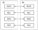
- FIG. 2 is a block diagram illustrating a radio protocol architecture for a user plane to which the present invention is applied.
- FIG. 3 is a block diagram illustrating a radio protocol structure for a control plane to which the present invention is applied.
- FIG 4 shows an example of a multi-carrier to which the present invention is applied.
- FIG. 5 is a diagram schematically illustrating a concept of uplink link transmission power to which the present invention is applied.
- FIG. 6 shows a structure of a MAC PDU for power reporting to which the present invention is applied.
- FIG. 7 shows an example of a MAC CE for power reporting to which the present invention is applied.
- FIG 8 shows an example of a MAC CE for power reporting according to an embodiment of the present invention.
- FIG 9 shows an example of a MAC CE for power reporting according to another embodiment of the present invention.
- FIG. 10 shows an example of a MAC CE for power reporting according to another embodiment of the present invention.
- FIG. 11 is a diagram illustrating a signaling scheme between a terminal and a base station according to an embodiment of the present invention.
- FIG. 12 is a block diagram illustrating a system structure in which an embodiment of the present invention is implemented.
- the present specification describes a communication network, and the work performed in the communication network is performed in the process of controlling the network and transmitting data in a system (for example, a base station) that manages the communication network, or a terminal linked to the network. Work can be done in a system (for example, a base station) that manages the communication network, or a terminal linked to the network. Work can be done in a system (for example, a base station) that manages the communication network, or a terminal linked to the network. Work can be done in a system (for example, a base station) that manages the communication network, or a terminal linked to the network. Work can be done in a system (for example, a base station) that manages the communication network, or a terminal linked to the network. Work can be done in a system (for example, a base station) that manages the communication network, or a terminal linked to the network. Work can be done in a system (for example, a base station) that manages the communication network, or a terminal linked to
- E-UTRAN Evolved-UMTS Terrestrial Radio Access Network
- LTE Long Term Evolution
- LTE-A Long Term Evolution
- the E-UTRAN includes a base station (BS) 20 that provides a control plane and a user plane to a user equipment (UE).
- the terminal 10 may be fixed or mobile and may be called by other terms such as a mobile station (MS), a user terminal (UT), a subscriber station (SS), a mobile terminal (MT), a wireless device (Wireless Device), and the like.
- the base station 20 refers to a fixed station communicating with the terminal 10, and may be referred to by other terms such as an evolved-NodeB (eNB), a base transceiver system (BTS), an access point, and the like.
- eNB evolved-NodeB
- BTS base transceiver system
- the cell should be interpreted in a comprehensive sense of a part of the area covered by the base station 11 and encompasses various coverage areas such as megacells, macrocells, microcells, picocells and femtocells.
- downlink means communication from the base station 11 to the terminal 12
- uplink means communication from the terminal 12 to the base station 11.
- the transmitter may be part of the base station 11 and the receiver may be part of the terminal 12.
- the transmitter may be part of the terminal 12 and the receiver may be part of the base station 11.
- CDMA Code Division Multiple Access
- TDMA Time Division Multiple Access
- FDMA Frequency Division Multiple Access
- OFDMA Orthogonal Frequency Division Multiple Access
- SC-FDMA Single Carrier-FDMA
- OFDM-FDMA OFDM-TDMA
- various multiple access schemes such as OFDM-CDMA may be used.
- the uplink transmission and the downlink transmission may use a time division duplex (TDD) scheme that is transmitted using different times, or may use a frequency division duplex (FDD) scheme that is transmitted using different frequencies.
- TDD time division duplex
- FDD frequency division duplex
- the base stations 20 may be connected to each other through an X2 interface.
- the base station 20 is connected to a Serving Gateway (S-GW) through an MME (Mobility Management Entity) and an S1-U through an Evolved Packet Core (EPC) 30, more specifically, an S1-MME through an S1 interface.
- S-GW Serving Gateway
- MME Mobility Management Entity
- S1-U S1-U
- EPC Evolved Packet Core
- EPC 30 includes MME, S-GW and P-GW (Packet Data Network-Gateway).
- the MME has access information of the terminal 10 or information on the capability of the terminal 10, and this information is mainly used for mobility management of the terminal 10.
- the S-GW is a gateway having an E-UTRAN as an endpoint
- the P-GW is a gateway having a PDN (Packet Data Network) as an endpoint.
- Layers of the Radio Interface Protocol between the terminal and the network are based on the lower three layers of the Open System Interconnection (OSI) reference model, which is widely known in communication systems.
- L2 second layer
- L3 third layer
- the RRC Radio Resource Control
- the RRC layer located in the third layer plays a role of controlling radio resources between the terminal and the network.
- the RRC layer exchanges an RRC message between the terminal and the base station.
- FIG. 2 is a block diagram illustrating a radio protocol architecture for a user plane.
- 3 is a block diagram illustrating a radio protocol structure for a control plane.
- the user plane is a protocol stack for transmitting user data
- the control plane is a protocol stack for transmitting control signals.
- the physical layer (PHY) layers 210 and 310 provide an information transfer service to a higher layer using a physical channel.
- the upper layer which is a medium access control (MAC) layer 220 and 320, is connected through a transport channel, and data is moved between the MAC layer and the physical layer through the transmission channel. It is classified according to how and with what characteristics data is transmitted through the interface.
- MAC medium access control
- the physical channel may be modulated by an orthogonal frequency division multiplexing (OFDM) scheme and utilizes time and frequency as radio resources.
- OFDM orthogonal frequency division multiplexing
- the function of the MAC layer 220 is to perform multiplexing / demultiplexing into a transport block provided as a physical channel on a transmission channel of a mapping channel between logical channels and transmission channels and a MAC service data unit (SDU) belonging to the logical channel. Include.
- the MAC layer provides a service to the Radio Link Control (RLC) layers 230 and 330 through a logical channel.
- RLC Radio Link Control
- the functionality of the RLC layer 230 includes concatenation, segmentation, and reassembly of RLC SDUs.
- the RLC layer In order to guarantee the various quality of service (QoS) required by the radio bearer (RB), the RLC layer has a transparent mode (TM), an unacknowledged mode (UM), and an acknowledged mode (Acknowledged Mode). Three modes of operation (AM).
- AM RLC provides error correction through an automatic repeat request (ARQ).
- PDCP Packet Data Convergence Protocol
- Functions of the Packet Data Convergence Protocol (PDCP) layers 240 and 340 in the user plane include the transfer of user data, header compression and ciphering.
- the functionality of the Packet Data Convergence Protocol (PDCP) layer in the user plane includes the transfer of control plane data and encryption / integrity protection.
- Radio resource control (RRC) layer 350 is defined only in the control plane.
- the RRC layer 350 is responsible for controlling logical channels, transmission channels, and physical channels in connection with configuration, re-configuration, and release of radio bearers.
- RB means a logical path provided by the first layer (PHY layer) and the second layer (MAC layer, RLC layer, PDCP layer) for data transmission between the terminal and the network.
- the configuration of the RB refers to a process of defining characteristics of a radio protocol layer and a channel and setting respective specific parameters and operations to provide a specific service.
- the RB may be further classified into a signaling RB (SRB) and a data RB (DRB).
- SRB is used as a path for transmitting RRC and NAS messages in the control plane
- DRB is used as a path for transmitting user data in the user plane.
- the UE If there is an RRC connection between the RRC layer of the UE and the RRC layer of the E-UTRAN, the UE is in an RRC connected state (also referred to as RRC connected mode), while otherwise the RRC idle state (also RRC idle mode).
- RRC connected state also referred to as RRC connected mode
- RRC idle state also RRC idle mode
- the NAS (Non-Access Stratum) control protocol 360 terminates at an MME on the network side to perform EPS bearer management, authentication, and encryption control.
- the downlink transmission channel includes a broadcast channel (BCH) for transmitting system information and a downlink shared channel (SCH) for transmitting user traffic or control messages.
- BCH broadcast channel
- SCH downlink shared channel
- User traffic or control messages for downlink multicast or broadcast services may be transmitted on the downlink-SCH or additionally downlink multicast channel (MCH).
- MCH downlink multicast channel
- Data may be transmitted from the terminal to the network through the uplink transmission.
- the uplink transmission channel includes a random access channel (RACH) for transmitting an initial control message and an uplink-SCH for transmitting user traffic or control messages.
- RACH random access channel
- An example of logical channels corresponding to a higher channel of a transmission channel mapped to transmission channels includes a broadcast channel (BCCH), a paging channel (PCCH), a common control channel (CCCH), and a multicast control channel (MCCH). And a farcast traffic channel (MTCH).
- BCCH broadcast channel
- PCCH paging channel
- CCCH common control channel
- MCCH multicast control channel
- MTCH farcast traffic channel
- the physical channel includes a plurality of OFDM symbols in the time domain and a plurality of subcarriers in the frequency domain.
- One subframe includes a plurality of OFDM symbols on the time axis.
- the resource block is a resource allocation unit and includes a plurality of OFDM symbols and subcarriers.
- each subframe uses a specific subcarrier of specific OFDM symbols (eg, first symbol) of the corresponding subframe for a physical downlink control channel (PDCCH), for example for an L1 / L2 control channel. do.
- the transmission time interval (TTI) is a time unit of subframe transmission.
- CA 4 is a diagram schematically illustrating a definition of carrier aggregation (CA) to which the present invention is applied.
- carrier aggregation may be divided into contiguous carrier aggregation formed between consecutive component carriers in a frequency domain and non-contiguous carrier aggregation formed between discontinuous component carriers.
- the number of carriers aggregated between the downlink and the uplink may be set differently. The case where the number of downlink component carriers and the number of uplink component carriers are the same is called symmetric aggregation, and when the number is different, it is called asymmetric aggregation.
- Adjacent carrier aggregation and / or non-adjacent carrier aggregation may be used in a multi-carrier system, and either symmetric aggregation or asymmetric aggregation may be used.
- the size (ie, bandwidth) of the component carriers may be different from each other.
- CC # 1, CC # 2, CC # 3, CC # 4, and CC # 5 each having a 20 MHz bandwidth. If five CCs are allocated for granularity, up to 100 MHz bandwidth can be supported.
- the bandwidth of the CC or the number of CC is just an example.
- the number of downlink CCs and the number of uplink CCs may be the same or different.
- the component carrier may be divided into a fully configured carrier and a partially configured carrier according to the direction.
- the preset carrier refers to a carrier capable of transmitting and / or receiving all control signals and data as a bidirectional carrier
- the partially configured carrier refers to a carrier capable of transmitting only downlink data to a unidirectional carrier.
- Partially configured carrier may be mainly used for multicast and broadcast service (MBS) and / or Single Frequency Network (SFN).
- the MAC layer may operate one or more CCs.
- the MAC layer may include one or more HARQ entities.
- One HARQ entity may perform HARQ on one CC.
- Each HARQ entity may independently process a transmission block on a transmission channel. Therefore, the plurality of HARQ entities may receive or transmit a plurality of transmission blocks through the plurality of CCs.
- One CC (or a CC pair of downlink CC and uplink CC) may correspond to one cell.
- each downlink CC may correspond to one serving cell.
- the terminal When a synchronization signal and system information are provided using each downlink CC, each downlink CC may correspond to one serving cell.
- the terminal When a terminal receives a service using a plurality of downlink CCs, the terminal may be provided with a service from a plurality of serving cells.
- the base station may provide a plurality of serving cells to the terminal using a plurality of downlink CC. Therefore, the base station and the terminal can communicate with each other using a plurality of serving cells.
- the serving cell may be divided into a primary serving cell and a secondary serving cell.
- the main serving cell is always active, operates at a primary frequency, initiates an RRC establishment or re-establishment procedure of the terminal, and provides security input and NAS mobility information.
- the secondary serving cell can be activated or deactivated, operates at the secondary frequency, can be established when an RRC connection is established, and used to provide additional radio resources.
- the primary serving cell may be configured as a pair of downlink CC and uplink CC
- the secondary serving cell may be configured as a pair of downlink CC and uplink CC or only a downlink CC.
- the terminal may include one main serving cell or one main serving cell and at least one secondary serving cell as a serving cell set according to its capabilities.
- the terminal cannot use all of the frequency bands, or the base station cannot properly receive the signal of the terminal due to insufficient power. do.
- the terminal reports that the surplus power is 1W to the base station, and the base station controls the transmission power so that scheduling can be performed within the surplus power range in consideration of the surplus power of the terminal.
- This report is called a surplus power report (Power Headroom Report, or PHR, Power Headroom Report). That is, the power headroom refers to power that can be used more than the transmission power currently used by the terminal.
- the power headroom may mean a difference between the maximum transmit power of the terminal and the transmit power currently used.
- the power headroom report is used to explicitly inform the base station of the difference between the terminal maximum transmit power and the estimated power due to UL-SCH transmission. Equation 1 below defines power headroom in subframe i.
- P CMAX is a set maximum terminal transmission power
- M PUSCH (i) is the bandwidth of the PUSCH resource allocation represented by the number of resource blocks in subframe i,
- PL is DL path loss estimation calculated by UE
- P O_PUSCH (j), ⁇ ( j), ⁇ TF (i) and f (i) is a parameter obtained from a higher layer signaling.
- PHR can be triggered as follows.
- At least one PHR has been triggered since the last transmission of the PHR and this is the first triggered PHR;
- LCR logical channel prioritization
- Power headroom is transmitted as a MAC CE (control element).
- RRC To trigger the power headroom report, i.e., RRC sets a pathloss threshold that sets a change in two timers (periodic timer and prohibit timer) and the measured DL pathloss.
- the path loss estimate is measured by the terminal based on a reference symbol received power (RSRP).
- RSRP reference symbol received power
- FIG. 5 is a diagram schematically illustrating a concept of a power headroom to which the present invention is applied.
- the set maximum transmit power Pcmax of the terminal is composed of P PH 505, P PUSCH 510, and P PUCCH 515. That is, the power is defined as P PH 505 in Pcmax except for P PUSCH 510 and P PUCCH 515.
- Each power is calculated in units of a transmission time interval (TTI). That is, the surplus power PH is defined as a difference between the maximum transmit power P cmax configured in the terminal and the estimated power P estimated for uplink transmission, as expressed by Equation 2, and are expressed in dB.
- TTI transmission time interval
- surplus power P PH may also be referred to as power headroom PH, remaining power, or surplus power. That is, the remaining value excluding the P estimated which is the sum of the transmit powers used in each CC from the maximum transmit power of the terminal set by the base station becomes the P PH value.
- P estimated is equal to the estimated power P PUSCH for transmission of a Physical Uplink Shared CHannel (PUSCH). Therefore, in this case, P PH can be obtained by ⁇ Equation 3>. Equation 3 is a case where only PUSCH is transmitted on an uplink, which is called Type 1. Surplus power according to Type 1 is called Type 1 surplus power.
- Equation 4 is a case where PUSCH and PUCCH are simultaneously transmitted in uplink, and this is called Type 2. Surplus power according to Type 2 is called Type 2 surplus power.
- the surplus power according to Equation 4 is represented as a graph on the time-frequency axis as shown in FIG. 5. 5 shows surplus power for one CC for ease of explanation.
- FIG. 6 shows a structure of a MAC PDU for power headroom reporting to which the present invention is applied.
- the MAC PDU 600 includes a MAC header 610, at least one MAC control element 620,..., 62n, and at least one MAC SDU. .66m) and padding 670.
- MAC control element 620 is a control message generated by the MAC layer.
- the MAC SDU 660 is the same as the RLC PDU delivered from the Radio Link Control (RLC) layer.
- Padding 670 is a predetermined number of bits added to make the size of the MAC PDU constant.
- the MAC control element 620, MAC SDU 660 and padding 670 together may be referred to as the MAC payload.
- the MAC header 610 includes at least one subheader 610-1, 610-2,..., 610-k, each subheader having one MAC SDU, one MAC control element. Corresponding in the order of, or padding.
- Each subheader 610 may include four fields, such as R, R, E, LCID, or six fields, such as R, R, E, LCID, F, and L.
- a subheader containing four fields is a subheader corresponding to a MAC control element or padding, and a subheader containing six fields is a subheader corresponding to a MAC SDU.
- LCID (5 bit): logical channel ID field. Indicates the type of logical channel or MAC CE to which the MAC SDU belongs.
- F (1 bit) format field. Indicates whether the next L field is 7 bit or 15 bit. .
- the F and L fields are not included in the MAC subheader corresponding to the MAC CE of the fixed size.
- the LCID field is an identification field for identifying a logical channel corresponding to a MAC SDU or for identifying a type of a MAC control element or padding and may be 5 bits.
- the value of the LCID may be set to 11001 or 11010 for surplus power reporting, as shown in ⁇ Table 1>.
- a plurality of TDD cells CAs that is, aggregates, have the same U / D (uplink-downlink or UL / DL) configuration frame structure. It is common to have
- Table 2 shows an example of a TDD uplink / downlink configuration (UL / DL configuration) of a radio frame.
- the TDD uplink / downlink configuration defines a subframe reserved for uplink transmission and a subframe reserved for downlink transmission within one TDD radio frame. That is, the TDD uplink / downlink configuration indicates which rule is allocated (or reserved) to the uplink and downlink in each subframe within one TDD radio frame.
- D indicates that the subframe is to be used for downlink transmission and U indicates that the subframe is to be used for uplink transmission.
- S is a special subframe, which indicates that the subframe is used for a special purpose, and is used for frame synchronization or downlink transmission. That is, the U / D timing between the TDD cells is synchronized, and at the same time, all of the plurality of TDD cells aggregated by the UE become U (Up) subframe timing or D (Down) subframe timing.
- the TDD uplink / downlink configuration of Table 2 may be transmitted from the base station to the terminal through the system information.
- the base station may inform the terminal of the change of the uplink-downlink allocation state of the radio frame by transmitting only the index of the TDD uplink / downlink configuration whenever the TDD uplink / downlink configuration is changed.
- the TDD uplink / downlink configuration may be control information transmitted in common to all terminals in a cell through a broadcast channel as broadcast information.
- the next system considers different U / D data traffic environment or interference environment for each cell, and maximizes the total cell data capacity in order to maximize the total cell data capacity. It may be considered to set different U / D configurations for each cell such that the D subframes are mixed. CAs of cells configured with such different U / D TDDs may be easy to implement since interference between UL transmission signals and DL transmission signals of different cells is relatively low, particularly in cells belonging to different bands.
- a terminal that aggregates a plurality of cells needs a scheme for effectively transmitting a PHR for each cell to a base station in an arbitrary subframe. That is, the terminal needs to specify a PHR for activated cells aggregated by the terminal.
- FIG. 7 shows an example of MAC CE for PHR in a wireless communication system to which the present invention is applied.
- the MAC CE for PHR may be identified by a MAC PDU subheader having an LCID corresponding to the MAC CE for PHR.
- the MAC CE may include a corresponding PH per serving cell and then include an octet that includes the associated P CMAX, c .
- the cell index of the cell of the serving cell and the associated P CMAX, c may be included.
- fields in the PHR may be defined as follows.
- Ci This indicates whether PH exists for the secondary cell of cell index i. If the Ci field is set to '1', the PH for the secondary cell of the cell index i is reported. If the Ci field is set to '0', the PH for the secondary cell of the cell index i is not reported.
- R reserved bit. It is set to '0'.
- PHLn This indicates the power headroom level (PHL) for the nth serving cell.
- n 1,... N is.
- Each PHL indicates the value of the corresponding PH.
- the transmit power (TP) field contains PCMAX, c used to calculate the previous PH.
- P CMAX, c may be set to one of the following Table 3 and transmitted.
- P CMAX, c assumes a power level for Extended PHR.
- the terminal transmits only Type 1 PHR or Type 2 PHR and Type 2 PHR according to the base station configuration.
- Type 2 PHR is transmitted only for PCell.
- the UE transmits PH (power headroom) 720, 730, and 7N0 values by subtracting the transmission power to be applied when the PUSCH is transmitted by the cell in the maximum allowable power Pcmax, c in the cell.
- Pcmax, c (725, 735, 7N5) values are also transmitted.
- the reason why the Pcmax, c value for the PUSCH is transmitted together is that when the UE actually transmits the PUSCH, the Pcmax, c value is adjusted according to the transmission mode (transmission bandwidth, transmission location, RB number, modulation order, etc.) of the PUSCH. This is because the base station does not know the value of Pcmax, c applied by the terminal, and only the PH value does not accurately determine the current transmission power of the terminal.
- the UE transmits the PH 710 value obtained by subtracting the total transmission power to be applied if the UE simultaneously transmits the PUSCH and the PUCCH in the maximum allowable power Pcmax, c in the cell.
- Pcmax, c 715 is also transmitted.
- the reason for transmitting the Pcmax, c value for the PUCCH together is that when the terminal actually transmits the PUCCH, the terminal can adjust the Pcmax, c value according to the transmission mode of the PUCCH, in this case the base station is applied by the terminal This is because the current transmit power of the terminal cannot be accurately known only by the PH value without knowing the exact Pcmax, c value.
- the PHR transmission always transmits a Type 1 PHR for each cell or, in the case of a Pcell, additionally transmits a Type 2 PHR transmission.
- PHR power headroom report
- the power headroom report as shown in FIG. 7 does not consider U / D configuration at all, and forms a MAC message including PH and Pcmax, c for all aggregated serving descriptions.
- the present invention clarifies the definition of UL PHR, and also discloses a UL PHR transmission scheme for efficiently using uplink resources according to the defined definition.
- FIG 8 shows an example of a MAC CE for power reporting according to an embodiment of the present invention.
- the UE transmits the PHR in an arbitrary subframe
- the UE does not transmit the PHR for the cell in which the corresponding subframe is set to DL, but instead transmits the PHR for the activated cell (s) set to UL.
- the present invention proposes a method of constructing and transmitting.
- the terminal is configured to transmit the PHR for the corresponding serving cell only when UL is set in the corresponding subframe. That is, if the PUSCH is transmitted for the activated secondary serving cell (s) set to UL, a power headroom (PH) value 830, 8N0 minus the transmission power to be applied, and Pcmax, c (835, 8N5) in the secondary serving cell Configure PHR to include the) value.
- PH power headroom
- the terminal configures the PHR report except for the PHR for the PCell.
- the PHR may be configured to include the PH and Pcmax, c for the secondary serving cell only when the PHR is always transmitted and the remaining secondary cells are always set to UL. Send.
- the UE saves time by reducing the PHR overhead burden on a cell that does not actually perform UL transmission, that is, does not perform calculation and configuration operations according to the PHR configuration for a cell in which no UL transmission occurs in a DL configuration. And by reducing the complexity, other UL data transmission efficiency can be increased.
- FIG 9 shows an example of a MAC CE for power reporting according to another embodiment of the present invention.
- the PCell Since the PCell does not transmit the PUCCH in the DL subframe, since the PH information considering the actual PUCCH transmission is not accurate, the PCell does not transmit the information. Instead, the other UL data transmission efficiency is increased by reducing the overhead burden on the PHR. Because it can.
- FIG. 9 includes Type 1 PH 920 and Pcmax, c2 925 considering only transmission of PCSCH PUSCH except for PUCCH transmission of Pcell according to DL configuration of PCell in any subframe, and UL.
- FIG. 10 shows an example of a MAC CE for power reporting according to another embodiment of the present invention.
- the UE when transmitting a PHR in an arbitrary subframe, the UE proposes to configure and transmit a PHR excluding Pcmax and c values for a serving cell in which a corresponding subframe is set to DL.
- the MAC message for the PHR is always transmitted with a 1-bit field indicating whether to transmit the Pcmax, c value and a 6-bit field corresponding to the Pcmax, c value, but in the present invention, the serving is set to DL.
- PHR is configured by excluding the 6-bit Pcmax and c fields. This is because the cell that is the DL subframe does not transmit the PUSCH or the PUCCH, so it is certain that the Pcmax, c information considering the actual PUSCH / PUCCH transmission state is not necessary.
- PH 1010 in consideration of simultaneous PUSCH and PUCCH transmission for a Pcell
- PH 1020 in consideration of PUSCH transmission
- Pcmax, c 1035, 10N5
- the PHR configuration and transmission described above with reference to FIGS. 8 to 10 may be applied not only when the UE aggregates TDD cells but also when TDD / FDD cells are aggregated. In addition, it is applicable not only when transmitting PHRs for multiple DL / UL resources on the frequency axis but also when transmitting PHRs for multiple DL / UL resources on the time axis or in other domains.
- the resource may be preset or adaptively set dynamically.
- the PHR configuration and transmission allows PHR transmission only when all activated cells are UL subframes in a TDD (or TDD / FDD) CA situation, or PHR transmission only when the PCell is an UL subframe. Can be allowed.
- FIG. 11 is a diagram illustrating a signaling scheme between a terminal and a base station according to an embodiment of the present invention.
- the terminal checks the UL / DL configuration for the serving cell (S 1110).
- the terminal checks the configuration setting of the subframe for each serving cell.
- the terminal determines the PH for each serving cell (S1120).
- P CMAX, c be the terminal maximum power set in subframe i of the serving cell c.
- PH may be determined in Equation 1 in subframe i of serving cell c.
- the UE checks the received UL / DL configuration and configures the PHR in consideration of the determined UL / DL in the corresponding subframe.
- the PHR may include information (s) about PH, P CMAX, c corresponding to the UL configured serving cell in the corresponding subframe.
- PHR is PH, P CMAX, (s) information relating to c corresponding to the taking into account only the least transmit the PCell PUSCH in other words, Type 1 PHR of PH, P CMAX, c and, the UL set the serving cell for the Pcell configured DL It may be included in addition to the PHR.
- the PHR is in the information (s) corresponding to the PH, P CMAX, c corresponding to the UL configured serving cell, except for P CMAX, c for Type 2 for the Pcell, and P CMAX, c for Type 1,
- P CMAX, c for Type 1 This means that a PHR including only a PH considering a PUSCH and a PUCCH of type 2 and a PH considering a PUSCH of a type 1 is configured.
- the terminal transmits the PHR to the base station (S1130). For example, the PHR transmission is transmitted through a MAC message. In addition, the PHR transmission does not exclude being transmitted in an RRC message.
- the terminal configures the MAC header to have an LCID of 11001, indicating that the MAC message is a message for the PHR.
- the base station checks power information, that is, PH for the corresponding serving cell transmitted from the terminal (S1140). In addition, it is confirmed that the available transmission power varies according to the UL / DL configuration in which the terminal is set in a specific subframe, that is, the available transmission power available for uplink transmission of the terminal may be known more accurately. Therefore, better link adaptation may be provided to the terminal (S1150).
- FIG. 12 is a block diagram illustrating an apparatus in which an embodiment of the present invention is implemented. This device may be part of a terminal.
- the device 1200 may include a processor 1220, a memory 1230, and a radio frequency unit 1210.
- the memory 1230 is connected to the processor 1220 and stores various information for driving the processor 1220.
- the RF unit 1230 is connected to the processor 1220 and transmits and / or receives a radio signal.
- the processor 1220 implements the proposed functions, processes, and / or methods. The operation of the terminal according to the above-described embodiments of FIGS. 8 to 11 may be implemented by the processor 1220.
- the processor 1220 checks the UL / DL configuration received by the RF unit 1210 and configures a power headroom report (PHR) in consideration of the determined UL / DL in the corresponding subframe.
- the processor 1220 may include a PH calculator and a message constructer for constructing a PHR message.
- the PH calculator in the processor 1220 calculates information about PH, P CMAX, c corresponding to the UL-configured serving cell in the corresponding subframe.
- information about PH, P CMAX, c may be calculated in correspondence with each of the UL / DL configured serving cells. This includes calculation of PH, P CMAX, c , which is a type 1 PHR, that is, considering transmission of at least a PCSCH PUSCH to a DL configured Pcell.
- the PHR message constructing unit in the processor 1220 configures a PHR including only information (s) of PH, P CMAX, c corresponding to the UL set serving cell, or PH, P CMAX, which is a Type 1 PHR for a Pcell. It can be configured to configure a PHR additionally including c .
- the PHR message constructing unit may include a PH considering the PUSCH and the PUCCH, which are Type 2 for the Pcell, and a PH considering the PUSCH, which is Type 1, in the information (s) corresponding to the PH, P CMAX, c corresponding to the UL configured serving cell. It may be configured to include a PHR. This includes that excluding P CMAX, c of the P CMAX, c and, for each Type 1 and Type 2, to configure the PHR.
- the processor constituting the PHR according to the present invention is provided in the terminal device.
- the above-described processor may be configured in the base station apparatus.
- the terminal device may perform a reverse operation of the terminal processor, that is, in a pair concept.
- the processor 1280 included in the base station may be provided as a PHR message obtainer and a scheduler.
- the PHR message acquisition unit in the processor of the base station may check the PHR reported value from the terminal, and the scheduler may perform an operation of more efficiently managing uplink resources of the terminal using the identified PHR.
- the processor may include application-specific integrated circuits (ASICs), other chipsets, logic circuits, and / or data processing devices.
- the memory may include read-only memory (ROM), random access memory (RAM), flash memory, memory card, storage medium and / or other storage device.
- the RF unit may include a baseband circuit for processing a radio signal.
- the above-described technique may be implemented as a module (process, function, etc.) for performing the above-described function.
- the module may be stored in memory and executed by a processor.
- the memory may be internal or external to the processor and may be coupled to the processor by various well known means.
Abstract
Provided are an apparatus and a method for reporting a power headroom in a wireless communication system. A terminal may check the configuration of a plurality of subframes for multiple serving cells, determine at least one power headroom (PH) in correspondence to at least one subframe corresponding to the subframe for which an uplink configuration is established, from among the plurality of subframes, and perform a power headroom report (PHR) including said at least one PH.
Description
본 발명은 무선 통신에 관한 것으로, 보다 상세하게는 무선 통신 시스템에서 요소 반송파에 대한 파워 헤드룸을 보고하는 장치 및 방법에 관한 것이다.The present invention relates to wireless communications, and more particularly, to an apparatus and method for reporting power headroom for a component carrier in a wireless communication system.
최근 차세대 무선 통신 시스템인 LTE(Long Term Evolution) 시스템의 상용화가 본격적으로 지원되고 있는 상황이다. 이러한 LTE 시스템은 단말 사용자의 활동성을 보장하면서 음성 서비스뿐만 아니라 사용자의 요구에 대한 대용량 서비스를 고품질로 지원하고자 하는 필요성이 인식된 후, 보다 빨리 확산되고 있는 추세이다. 상기 LTE 시스템은 낮은 송신 지연, 높은 송신율, 시스템 용량과 커버리지 개선을 제공한다. Recently, commercialization of the LTE (Long Term Evolution) system, which is the next generation wireless communication system, is being supported in earnest. The LTE system is spreading more quickly after the need to support high-quality services for high-quality services as well as voice services while ensuring the activity of terminal users. The LTE system provides low transmission delay, high transmission rate, system capacity and coverage improvement.
이를 위해 LTE 시스템은 반송파 집성(carrier aggregation, 이하 ‘CA’라 칭함)을 지원한다. 상기 CA는 복수의 반송파를 지원하는 것을 의미하는 것으로서, 스펙트럼 집성 또는 대역폭 집성(bandwidth aggregation)이라고도 불리 운다. 즉, 복수의 반송파를 통해 광대역으로 데이터를 송신 및/또는 수신할 수 있도록 다중 요소 반송파(Multiple Component Carrier)를 지원한다. 여기서, 반송파 집성에 의해 묶이는 개별적인 단위 반송파는 요소 반송파(component carrier, CC)라고 한다. 각 요소 반송파는 대역폭과 중심 주파수로 정의된다. To this end, the LTE system supports carrier aggregation (hereinafter, referred to as "CA"). The CA is meant to support a plurality of carriers, also called spectrum aggregation or bandwidth aggregation (bandwidth aggregation). That is, multiple component carriers are supported to transmit and / or receive data over a wide range of carriers. Here, the individual unit carriers bound by the carrier aggregation are called component carriers (CCs). Each component carrier is defined by a bandwidth and a center frequency.
높은 송신율 지원을 위하여, 즉, 송신 용량을 높이기 위해서 대역폭을 늘리는 것이 필수적이라 할 수 있지만, 요구되는 서비스의 수준이 낮은 경우에도 큰 대역폭을 지원하는 것은 커다란 전력 소모를 야기할 수 있다. 한편, 기지국은 단말의 자원을 효율적으로 활용하기 위한 방안으로 단말의 전력정보를 이용할 수 있다. 이러한 기지국의 전력제어 기술은 무선통신에서 자원의 효율적 배분을 위해 간섭요소를 최소화하고 단말의 배터리 소모를 줄이기 위한 필수 핵심기술이다. 이를 위해, 단말은 기지국에 의해 할당해주는 송신전력제어(Transmit Power Control, TPC), 변조 및 코딩 수준(Modulation and Coding Scheme, MCS), 대역폭등의 스케줄링 정보에 따라 상향링크 송신전력을 결정할 수 있다. In order to support high transmission rate, that is, increase bandwidth in order to increase transmission capacity, it may be necessary to support a large bandwidth even when a required level of service is low, which can cause a large power consumption. On the other hand, the base station may use the power information of the terminal as a method for efficiently utilizing the resources of the terminal. The power control technology of the base station is an essential core technology for minimizing interference and reducing battery consumption of the terminal for efficient allocation of resources in wireless communication. To this end, the terminal may determine the uplink transmission power according to scheduling information such as transmit power control (TPC), modulation and coding level (MCS), bandwidth, etc. allocated by the base station.
또한, 다중 요소 반송파의 도입으로 인해 각 요소 반송파의 상향링크 송신전력이 종합적으로 고려되어야 하므로, 단말의 전력제어는 더욱 복잡해지는 상황에 직면하고 있다. 이러한 복잡성은 단말의 최대송신전력(Maximum Transmission Power) 측면에서 문제를 야기할 수 있다. 일반적으로 단말은 허용 가능한 범위의 송신전력인 최대송신전력보다 낮은 전력에 의해 동작해야 한다. 만약 기지국이 상기 최대송신전력 이상의 송신전력을 요구하는 스케줄링을 할 경우, 실제 상향링크 송신전력이 상기 단말의 최대송신전력을 초과하는 문제를 일으킬 수 있다. In addition, due to the introduction of a multi-component carrier, the uplink transmission power of each component carrier must be considered as a whole, and thus, the power control of the terminal is more complicated. This complexity may cause problems in terms of maximum transmission power of the terminal. In general, the terminal should be operated by a power lower than the maximum transmission power that is the transmission power of the allowable range. If the base station schedules the transmission power more than the maximum transmission power, it may cause a problem that the actual uplink transmission power exceeds the maximum transmission power of the terminal.
따라서, 단말과 기지국간에 상향링크 송신전력에 관한 정보가 충분히 공유되어야 할 필요성이 있으며, 특히, 송신전력을 효율적으로 조절하기 위한 파워 헤드룸에 대한 효율적인 시그널링 방안이 필요한 실정이다. Accordingly, there is a need for sufficient information about the uplink transmission power between the terminal and the base station. In particular, an efficient signaling scheme for power headroom for efficiently adjusting the transmission power is needed.
본 발명은 무선 통신 시스템에서 요소 반송파에 대한 파워 헤드룸을 보고하는 장치 및 방법을 제공한다. The present invention provides an apparatus and method for reporting power headroom for component carriers in a wireless communication system.
또한, 본 발명은 무선 통신 시스템에서 다수의 요소 반송파에 대한 전력 정보를 구성하는 장치 및 방법을 제공한다. The present invention also provides an apparatus and method for configuring power information for a plurality of CCs in a wireless communication system.
또한, 본 발명은 다중 요소 반송파를 지원하는 무선 통신 시스템에서 파워 헤드룸 보고 메시지를 구성하는 장치 및 방법을 제공한다. The present invention also provides an apparatus and method for constructing a power headroom report message in a wireless communication system supporting multiple component carriers.
또한, 본 발명은 다중 요소 반송파를 지원하는 무선 통신 시스템에 상향링크 구성이 설정된 서빙셀에 대한 파워 헤드룸을 구성 및 보고하는 장치 및 방법을 제공한다. The present invention also provides an apparatus and method for configuring and reporting a power headroom for a serving cell in which an uplink configuration is configured in a wireless communication system supporting multiple component carriers.
본 발명의 일 실시 예에 따르면, 무선 통신 시스템에서 단말의 파워 헤드룸 보고(PHR) 방법에 있어서, 다수의 서빙셀들에 대한 복수의 서브프레임들의 구성을 결정하는 과정과; 상기 복수의 서브프레임들 중 상향링크 구성이 설정된 서브프레임에 해당되는 적어도 하나의 서브프레임에 대응하여 적어도 하나의 파워 헤드룸(PH)을 결정하는 과정과; 상기 적어도 하나의 PH를 포함하는 파워 헤드룸 보고(PHR)를 생성하여 전송하는 과정을 포함함을 특징으로 한다. According to an embodiment of the present invention, a method of power headroom reporting (PHR) of a terminal in a wireless communication system, the method comprising: determining a configuration of a plurality of subframes for a plurality of serving cells; Determining at least one power headroom (PH) corresponding to at least one subframe corresponding to a subframe in which an uplink configuration is configured among the plurality of subframes; And generating and transmitting a power headroom report (PHR) including the at least one PH.
이러한 본 발명은, 상기 복수의 서브프레임들 중 하향링크 구성이 설정된 서브프레임에 해당되는 적어도 하나의 서브프레임에 대응하여 적어도 하나의 파워 헤드룸(PH)을 제외하여, 상기 PHR을 생성하여 전송하는 과정을 포함함을 특징으로 한다. The present invention, except for at least one power headroom (PH) corresponding to at least one subframe corresponding to a subframe of the downlink configuration of the plurality of subframes to generate and transmit the PHR Characterized by including the process.
본 발명의 또 다른 실시 예에 따르면, 무선통신 시스템에서 파워 헤드룸을 보고하는 장치에 있어서, 무선 신호를 송신 및 수신하는 RF(radio frequency)부와, 기 RF부와 연결되는 프로세서를 포함하되, 상기 프로세서는 다수의 서빙셀들에 대한 복수의 서브프레임들의 구성을 결정하고, 상기 복수의 서브프레임들 중 상향링크 구성이 설정된 서브프레임에 해당되는 적어도 하나의 서브프레임에 대응하여 적어도 하나의 파워 헤드룸(PH)을 결정하여, 상기 적어도 하나의 PH를 포함하는 파워 헤드룸 보고(PHR)를 생성함을 특징으로 한다. According to another embodiment of the present invention, an apparatus for reporting power headroom in a wireless communication system, the apparatus comprising a radio frequency (RF) unit for transmitting and receiving a radio signal and a processor connected to the existing RF unit, The processor determines a configuration of a plurality of subframes for a plurality of serving cells and at least one power head corresponding to at least one subframe corresponding to a subframe in which an uplink configuration is configured among the plurality of subframes. The room PH is determined to generate a power headroom report PHR including the at least one PH.
기지국이 단말로부터 상향링크 전송이 구성된 적어도 하나의 서빙셀에 대한 송신전력을 확인하여, 단말의 실제 상향링크 송신에 사용될 수 있는 가용한 송신 파워를 정확히 파악할 수 있는 장점이 있다. 또한, 최적화된 파워 헤드룸 보고를 통해, 상기 파워 헤드룸 보고를 위한 메시지 구성 및 계산에 대한 복잡도를 간소화한다. 이를 통해, 한정된 상향링크 자원을 효율적으로 사용하게 되는 장점을 제공한다. The base station checks the transmission power of at least one serving cell in which uplink transmission is configured from the terminal, so that the available transmission power that can be used for the actual uplink transmission of the terminal can be accurately identified. In addition, optimized power headroom reporting simplifies the complexity of message construction and computation for power headroom reporting. This provides an advantage of efficiently using limited uplink resources.
또한, 반송파 집성을 지원하는 무선 통신 시스템에서 단말로 하여금 상향링크 전송이 존재하는 적어도 하나의 요소 반송파에 대한, 정확한 전력 정보를 제공토록하여 MAC 제어 요소상의 자원 낭비없는 파워 헤드룸 보고를 구성하도록 할 수 있다. 이를 통해, MAC 메시지의 최적화 및 송신전력에 대한 기지국의 스케줄링 효율성을 도모하는 장점을 가진다. In addition, in a wireless communication system supporting carrier aggregation, a terminal may provide accurate power information on at least one component carrier in which uplink transmission exists to configure power headroom reporting without wasting resources on a MAC control element. Can be. In this way, the scheduling efficiency of the base station for the optimization and transmission power of the MAC message has the advantage.
도 1은 본 발명이 적용되는 무선통신 시스템을 나타낸다.1 shows a wireless communication system to which the present invention is applied.
도 2는 본 발명이 적용되는 사용자 평면(user plane)에 대한 무선 프로토콜 구조(radio protocol architecture)를 나타낸 블록도이다. 2 is a block diagram illustrating a radio protocol architecture for a user plane to which the present invention is applied.
도 3은 본 발명이 적용되는 제어 평면(control plane)에 대한 무선 프로토콜 구조를 나타낸 블록도이다.3 is a block diagram illustrating a radio protocol structure for a control plane to which the present invention is applied.
도 4는 본 발명이 적용되는 다중 반송파의 일 예를 보여준다. 4 shows an example of a multi-carrier to which the present invention is applied.
도 5는 본 발명이 적용되는 상항링크 송신전력에 대한 개념을 개략적으로 도시한 도면이다. FIG. 5 is a diagram schematically illustrating a concept of uplink link transmission power to which the present invention is applied.
도 6은 본 발명이 적용되는 전력 보고를 위한 MAC PDU의 구조를 보여준다.6 shows a structure of a MAC PDU for power reporting to which the present invention is applied.
도 7은 본 발명이 적용되는 전력 보고를 위한 MAC CE의 일 예를 보여준다.7 shows an example of a MAC CE for power reporting to which the present invention is applied.
도 8은 본 발명의 일 실시 예에 따른 전력 보고를 위한 MAC CE의 일 예를 보여준다.8 shows an example of a MAC CE for power reporting according to an embodiment of the present invention.
도 9는 본 발명의 다른 실시 예에 따른 전력 보고를 위한 MAC CE의 일 예를 보여준다.9 shows an example of a MAC CE for power reporting according to another embodiment of the present invention.
도 10은 본 발명의 또 다른 실시 예에 따른 전력 보고를 위한 MAC CE의 일 예를 보여준다.10 shows an example of a MAC CE for power reporting according to another embodiment of the present invention.
도 11은 본 발명의 실시 예에 따른 단말과 기지국간의 시그널링 방안을 도시한 도면이다. 11 is a diagram illustrating a signaling scheme between a terminal and a base station according to an embodiment of the present invention.
도 12는 본 발명의 실시 예가 구현되는 시스템 구조를 도시한 블록도이다.12 is a block diagram illustrating a system structure in which an embodiment of the present invention is implemented.
이하, 본 명세서에서는 일부 실시 예들을 예시적인 도면을 통해 상세하게 설명한다. 각 도면의 구성 요소들에 참조 부호를 부가함에 있어서, 동일한 구성 요소들에 대해서는 비록 다른 도면상에 표시되더라도 가능한 한 동일한 부호를 가지도록 하고 있음에 유의해야 한다. 또한, 본 명세서의 실시 예를 설명함에 있어, 관련된 공지 구성 또는 기능에 대한 구체적인 설명이 본 명세서의 요지를 흐릴 수 있다고 판단되는 경우에는 그 상세한 설명은 생략한다.Hereinafter, some embodiments will be described in detail with reference to the accompanying drawings. In adding reference numerals to the components of each drawing, it should be noted that the same reference numerals are used as much as possible even though they are shown in different drawings. In addition, in describing the embodiments of the present specification, when it is determined that a detailed description of a related well-known configuration or function may obscure the gist of the present specification, the detailed description thereof will be omitted.
본 명세서는 통신 네트워크를 대상으로 설명하며, 통신 네트워크에서 이루어지는 작업은 해당 통신 네트워크를 관할하는 시스템(예를 들어 기지국)에서 네트워크를 제어하고 데이터를 송신하는 과정에서 이루어지거나, 해당 네트워크에 링크된 단말에서 작업이 이루어질 수 있다. The present specification describes a communication network, and the work performed in the communication network is performed in the process of controlling the network and transmitting data in a system (for example, a base station) that manages the communication network, or a terminal linked to the network. Work can be done in
도 1은 본 발명이 적용되는 무선통신 시스템을 나타낸다. 이는 E-UTRAN(Evolved-UMTS Terrestrial Radio Access Network), 또는 LTE(Long Term Evolution)/LTE-A 시스템이라고도 불리며, 음성, 패킷 데이터 등과 같은 다양한 통신 서비스를 제공하기 위한 패킷 기반의 시스템이다.1 shows a wireless communication system to which the present invention is applied. This is also called an Evolved-UMTS Terrestrial Radio Access Network (E-UTRAN), or Long Term Evolution (LTE) / LTE-A system, and is a packet-based system for providing various communication services such as voice and packet data.
E-UTRAN은 단말(10; User Equipment, UE)에게 제어 평면(control plane)과 사용자 평면(user plane)을 제공하는 기지국(20; Base Station, BS)을 포함한다. 단말(10)은 고정되거나 이동성을 가질 수 있으며, MS(Mobile station), UT(User Terminal), SS(Subscriber Station), MT(mobile terminal), 무선기기(Wireless Device) 등 다른 용어로 불릴 수 있다. 기지국(20)은 단말(10)과 통신하는 고정된 지점(fixed station)을 말하며, eNB(evolved-NodeB), BTS(Base Transceiver System), 액세스 포인트(Access Point) 등 다른 용어로 불릴 수 있다. 셀은 기지국(11)이 커버하는 일부 영역을 나타내는 포괄적인 의미로 해석되어야 하며, 메가셀, 매크로셀, 마이크로셀, 피코셀, 펨토셀 등 다양한 커버리지 영역을 모두 포괄하는 의미이다.The E-UTRAN includes a base station (BS) 20 that provides a control plane and a user plane to a user equipment (UE). The terminal 10 may be fixed or mobile and may be called by other terms such as a mobile station (MS), a user terminal (UT), a subscriber station (SS), a mobile terminal (MT), a wireless device (Wireless Device), and the like. . The base station 20 refers to a fixed station communicating with the terminal 10, and may be referred to by other terms such as an evolved-NodeB (eNB), a base transceiver system (BTS), an access point, and the like. The cell should be interpreted in a comprehensive sense of a part of the area covered by the base station 11 and encompasses various coverage areas such as megacells, macrocells, microcells, picocells and femtocells.
이하에서 하향링크(downlink)는 기지국(11)에서 단말(12)로의 통신을 의미하며, 상향링크(uplink)는 단말(12)에서 기지국(11)으로의 통신을 의미한다. 하향링크에서 송신기는 기지국(11)의 일부분일 수 있고, 수신기는 단말(12)의 일부분일 수 있다. 상향링크에서 송신기는 단말(12)의 일부분일 수 있고, 수신기는 기지국(11)의 일부분일 수 있다. In the following, downlink means communication from the base station 11 to the terminal 12, and uplink means communication from the terminal 12 to the base station 11. In downlink, the transmitter may be part of the base station 11 and the receiver may be part of the terminal 12. In uplink, the transmitter may be part of the terminal 12 and the receiver may be part of the base station 11.
또한, 본 발명이 적용되는 무선 통신 시스템에 적용되는 다중 접속 기법에는 제한이 없다. CDMA(Code Division Multiple Access), TDMA(Time Division Multiple Access), FDMA(Frequency Division Multiple Access), OFDMA(Orthogonal Frequency Division Multiple Access), SC-FDMA(Single Carrier-FDMA), OFDM-FDMA, OFDM-TDMA, OFDM-CDMA와 같은 다양한 다중 접속 기법을 사용할 수 있다. 상향링크 전송 및 하향링크 전송은 서로 다른 시간을 사용하여 전송되는 TDD(Time Division Duplex) 방식이 사용될 수 있고, 또는 서로 다른 주파수를 사용하여 전송되는 FDD(Frequency Division Duplex) 방식이 사용될 수 있다. In addition, there is no limitation on the multiple access scheme applied to the wireless communication system to which the present invention is applied. Code Division Multiple Access (CDMA), Time Division Multiple Access (TDMA), Frequency Division Multiple Access (FDMA), Orthogonal Frequency Division Multiple Access (OFDMA), Single Carrier-FDMA (SC-FDMA), OFDM-FDMA, OFDM-TDMA For example, various multiple access schemes such as OFDM-CDMA may be used. The uplink transmission and the downlink transmission may use a time division duplex (TDD) scheme that is transmitted using different times, or may use a frequency division duplex (FDD) scheme that is transmitted using different frequencies.
기지국(20)들은 X2 인터페이스를 통하여 서로 연결될 수 있다. 기지국(20)은 S1 인터페이스를 통해 EPC(Evolved Packet Core, 30), 보다 상세하게는 S1-MME를 통해 MME(Mobility Management Entity)와 S1-U를 통해 S-GW(Serving Gateway)와 연결된다. 여기서, MME는 제어 평면 기능들을 주관(host)하고, S-GW가 사용자 평면 기능들을 주관한다. The base stations 20 may be connected to each other through an X2 interface. The base station 20 is connected to a Serving Gateway (S-GW) through an MME (Mobility Management Entity) and an S1-U through an Evolved Packet Core (EPC) 30, more specifically, an S1-MME through an S1 interface. Here, the MME hosts the control plane functions, and the S-GW hosts the user plane functions.
EPC(30)는 MME, S-GW 및 P-GW(Packet Data Network-Gateway)를 포함한다. MME는 단말(10)의 접속 정보나 단말(10)의 능력에 관한 정보를 가지고 있으며, 이러한 정보는 단말(10)의 이동성 관리에 주로 사용된다. S-GW는 E-UTRAN을 종단점으로 갖는 게이트웨이이며, P-GW는 PDN(Packet Data Network)을 종단점으로 갖는 게이트웨이이다. EPC 30 includes MME, S-GW and P-GW (Packet Data Network-Gateway). The MME has access information of the terminal 10 or information on the capability of the terminal 10, and this information is mainly used for mobility management of the terminal 10. The S-GW is a gateway having an E-UTRAN as an endpoint, and the P-GW is a gateway having a PDN (Packet Data Network) as an endpoint.
단말과 네트워크 사이의 무선 인터페이스 프로토콜(Radio Interface Protocol)의 계층들은 통신시스템에서 널리 알려진 개방형 시스템간 상호접속(Open System Interconnection, OSI) 기준 모델의 하위 3개 계층을 바탕으로 L1(제1계층), L2(제2계층), L3(제3계층)로 구분될 수 있는데, 이 중에서 제1계층에 속하는 물리계층은 물리채널(Physical Channel)을 이용한 정보송신서비스(Information Transfer Service)를 제공하며, 제3계층에 위치하는 RRC(Radio Resource Control) 계층은 단말과 네트워크 간에 무선자원을 제어하는 역할을 수행한다. 이를 위해 RRC 계층은 단말과 기지국간 RRC 메시지를 교환한다. Layers of the Radio Interface Protocol between the terminal and the network are based on the lower three layers of the Open System Interconnection (OSI) reference model, which is widely known in communication systems. L2 (second layer), L3 (third layer) can be divided into, wherein the physical layer belonging to the first layer provides an information transfer service (Information Transfer Service) using a physical channel, The RRC (Radio Resource Control) layer located in the third layer plays a role of controlling radio resources between the terminal and the network. To this end, the RRC layer exchanges an RRC message between the terminal and the base station.
도 2는 사용자 평면(user plane)에 대한 무선 프로토콜 구조(radio protocol architecture)를 나타낸 블록도이다. 도 3은 제어 평면(control plane)에 대한 무선 프로토콜 구조를 나타낸 블록도이다. 사용자 평면은 사용자 데이터 송신을 위한 프로토콜 스택(protocol stack)이고, 제어 평면은 제어신호 송신을 위한 프로토콜 스택이다.FIG. 2 is a block diagram illustrating a radio protocol architecture for a user plane. 3 is a block diagram illustrating a radio protocol structure for a control plane. The user plane is a protocol stack for transmitting user data, and the control plane is a protocol stack for transmitting control signals.
도 2 및 도 3을 참조하면, 물리계층(PHY(physical) layer(210, 310)은 물리채널(physical channel)을 이용하여 상위 계층에게 정보 송신 서비스(information transfer service)를 제공한다. 물리계층은 상위 계층인 매체접근제어(Medium Access Control, MAC)(220,320) 계층과는 송신채널(transport channel)을 통해 연결되어 있다. 송신채널을 통해 MAC 계층과 물리계층 사이로 데이터가 이동한다. 송신채널은 무선 인터페이스를 통해 데이터가 어떻게 어떤 특징으로 송신되는가에 따라 분류된다. 2 and 3, the physical layer (PHY) layers 210 and 310 provide an information transfer service to a higher layer using a physical channel. The upper layer, which is a medium access control (MAC) layer 220 and 320, is connected through a transport channel, and data is moved between the MAC layer and the physical layer through the transmission channel. It is classified according to how and with what characteristics data is transmitted through the interface.
그리고 서로 다른 물리계층간에는, 즉 송신기의 물리계층과 수신기의 물리 계층 간에는, 물리채널을 통해 데이터가 이동한다. 상기 물리채널은 OFDM(Orthogonal Frequency Division Multiplexing) 방식으로 변조될 수 있으며, 시간과 주파수를 무선자원으로 활용한다. Data is transferred through different physical layers, that is, between the physical layer of the transmitter and the physical layer of the receiver. The physical channel may be modulated by an orthogonal frequency division multiplexing (OFDM) scheme and utilizes time and frequency as radio resources.
MAC 계층(220)의 기능은 논리채널과 송신채널간의 맵핑 및 논리채널에 속하는 MAC SDU(service data unit)의 송신채널 상으로 물리채널로 제공되는 송신블록(transport block)으로의 다중화/역다중화를 포함한다. MAC 계층은 논리채널을 통해 RLC(Radio Link Control)(230,330) 계층에게 서비스를 제공한다. The function of the MAC layer 220 is to perform multiplexing / demultiplexing into a transport block provided as a physical channel on a transmission channel of a mapping channel between logical channels and transmission channels and a MAC service data unit (SDU) belonging to the logical channel. Include. The MAC layer provides a service to the Radio Link Control (RLC) layers 230 and 330 through a logical channel.
RLC 계층(230)의 기능은 RLC SDU의 연결(concatenation), 분할(segmentation) 및 재결합(reassembly)를 포함한다. 무선 베어러(RB: Radio Bearer)가 요구하는 다양한 QoS(Quality of Service)를 보장하기 위해, RLC 계층은 투명모드(Transparent Mode, TM), 비확인 모드(Unacknowledged Mode, UM) 및 확인모드(Acknowledged Mode, AM)의 세 가지의 동작모드를 제공한다. AM RLC는 ARQ(automatic repeat request)를 통해 오류 정정을 제공한다. The functionality of the RLC layer 230 includes concatenation, segmentation, and reassembly of RLC SDUs. In order to guarantee the various quality of service (QoS) required by the radio bearer (RB), the RLC layer has a transparent mode (TM), an unacknowledged mode (UM), and an acknowledged mode (Acknowledged Mode). Three modes of operation (AM). AM RLC provides error correction through an automatic repeat request (ARQ).
사용자 평면에서의 PDCP(Packet Data Convergence Protocol)(240, 340) 계층의 기능은 사용자 데이터의 전달, 헤더 압축(header compression) 및 암호화(ciphering)를 포함한다. 사용자 평면에서의 PDCP(Packet Data Convergence Protocol) 계층의 기능은 제어 평면 데이터의 전달 및 암호화/무결정 보호(integrity protection)를 포함한다. Functions of the Packet Data Convergence Protocol (PDCP) layers 240 and 340 in the user plane include the transfer of user data, header compression and ciphering. The functionality of the Packet Data Convergence Protocol (PDCP) layer in the user plane includes the transfer of control plane data and encryption / integrity protection.
무선 자원 제어(RRC) 계층(350)은 오직 제어 평면에서만 정의된다. RRC 계층(350)은 무선 베어러(Radio Bearers)들의 구성(configuration), 재구성(re-configuration) 및 해제(release)와 관련되어 논리채널, 송신채널 및 물리채널들의 제어를 담당한다. RB는 단말과 네트워크간의 데이터 전달을 위해 제1 계층(PHY 계층) 및 제2 계층(MAC 계층, RLC 계층, PDCP 계층)에 의해 제공되는 논리적 경로를 의미한다. Radio resource control (RRC) layer 350 is defined only in the control plane. The RRC layer 350 is responsible for controlling logical channels, transmission channels, and physical channels in connection with configuration, re-configuration, and release of radio bearers. RB means a logical path provided by the first layer (PHY layer) and the second layer (MAC layer, RLC layer, PDCP layer) for data transmission between the terminal and the network.
RB가 구성된다는 것은 특정 서비스를 제공하기 위해 무선 프로토콜 계층 및 채널의 특성을 규정하고, 각각의 구체적인 파라미터 및 동작을 설정하는 과정을 의미한다. RB는 다시 SRB(Signaling RB), DRB(Data RB)로 구분될 수 있다. SRB는 제어 평면에서 RRC 메시지 및 NAS 메시지를 송신하는 통로로 사용되며, DRB는 사용자 평면에서 사용자 데이터를 송신하는 통로로 사용된다. The configuration of the RB refers to a process of defining characteristics of a radio protocol layer and a channel and setting respective specific parameters and operations to provide a specific service. The RB may be further classified into a signaling RB (SRB) and a data RB (DRB). The SRB is used as a path for transmitting RRC and NAS messages in the control plane, and the DRB is used as a path for transmitting user data in the user plane.
단말의 RRC 계층과 E-UTRAN의 RRC 계층 사이에 RRC 연결(RRC Connection)이 있을 경우, 단말은 RRC 연결 상태(또한 RRC connected 모드로 칭함)에 있게 되고, 반면에 그렇지 못할 경우 RRC 휴지 상태(또한 RRC idle 모드로 칭함)에 있게 된다. 몇몇 물리 제어채널들이 있다. If there is an RRC connection between the RRC layer of the UE and the RRC layer of the E-UTRAN, the UE is in an RRC connected state (also referred to as RRC connected mode), while otherwise the RRC idle state (also RRC idle mode). There are several physical control channels.
NAS(Non-Access Stratum) 제어 프로토콜(360)은 네트워크측의 MME에 종단되어 EPS 베어러 관리, 인증(Authentication), 암호화 제어를 수행한다.The NAS (Non-Access Stratum) control protocol 360 terminates at an MME on the network side to perform EPS bearer management, authentication, and encryption control.
데이터는 하향링크 송신 채널을 통해 네트워크에서 단말로 송신된다. 일 예로, 하향링크 송신 채널은 시스템 정보를 송신하기 위한 브로드캐스트 채널(BCH)과 사용자 트래픽 또는 제어 메시지를 송신하기 위한 하향링크 공용 채널(SCH)을 포함한다. 하향링크 멀티캐스트 또는 브로드캐스트 서비스들에 대한 사용자 트래픽 또는 제어 메시지들은 하향링크-SCH 또는 추가적으로 하향링크 멀티캐스트 채널(MCH)을 통해 송신될 수 있다. 데이터는 상향링크 송신을 통해 단말에서 네트워크로 송신될 수도 있다. 일 예로, 상향링크 송신 채널은 초기 제어 메시지를 송신하기 위한 랜덤 액세스 채널(RACH)와 사용자 트래픽 또는 제어 메시지들을 송신하기 위한 상향링크-SCH를 포함한다. Data is transmitted from the network to the terminal through the downlink transmission channel. As an example, the downlink transmission channel includes a broadcast channel (BCH) for transmitting system information and a downlink shared channel (SCH) for transmitting user traffic or control messages. User traffic or control messages for downlink multicast or broadcast services may be transmitted on the downlink-SCH or additionally downlink multicast channel (MCH). Data may be transmitted from the terminal to the network through the uplink transmission. For example, the uplink transmission channel includes a random access channel (RACH) for transmitting an initial control message and an uplink-SCH for transmitting user traffic or control messages.
송신 채널들에 매핑되는 송신 채널의 상위 채널에 해당하는 논리채널들에 대한 일 예로는, 브로드캐스트 채널(BCCH), 페이징 채널(PCCH), 공용 제어 채널(CCCH), 멀티캐스트 제어 채널(MCCH), 멀리캐스트 트래픽 채널(MTCH)등이 있다. An example of logical channels corresponding to a higher channel of a transmission channel mapped to transmission channels includes a broadcast channel (BCCH), a paging channel (PCCH), a common control channel (CCCH), and a multicast control channel (MCCH). And a farcast traffic channel (MTCH).
물리 채널은 시간 영역(domain)에서 다수의 OFDM 심볼들을 그리고 주파수 영역으로 다수의 서브캐리어들을 포함한다. 하나의 서브프레임은 시간 축으로 다수의 OFDM 심볼들을 포함한다. 자원 블록은 자원 할당 단위로, 다수의 OFDM 심볼들과 서브캐리어들을 포함한다. 부가적으로, 각 서브프레임은 물리 하향링크 제어 채널을 위하여(PDCCH), 일 예로 L1/L2 제어 채널을 위해, 해당하는 서브프레임의 특정 OFDM 심볼들(예로, 첫번째 심볼)의 특정 서브캐리어를 사용한다. 송신 시간 구간(TTI)는 서브프레임 송신의 시간 단위이다. The physical channel includes a plurality of OFDM symbols in the time domain and a plurality of subcarriers in the frequency domain. One subframe includes a plurality of OFDM symbols on the time axis. The resource block is a resource allocation unit and includes a plurality of OFDM symbols and subcarriers. In addition, each subframe uses a specific subcarrier of specific OFDM symbols (eg, first symbol) of the corresponding subframe for a physical downlink control channel (PDCCH), for example for an L1 / L2 control channel. do. The transmission time interval (TTI) is a time unit of subframe transmission.
도 4는 본 발명이 적용되는 반송파 집성(CA)에 대한 정의를 개략적으로 도시한 도면이다. 4 is a diagram schematically illustrating a definition of carrier aggregation (CA) to which the present invention is applied.
도 4를 참조하면, 반송파 집성은 주파수 영역에서 연속적인 요소 반송파들 사이에서 이루어지는 인접(contiguous) 반송파 집성과 불연속적인 요소 반송파들 사이에 이루어지는 비인접(non-contiguous) 반송파 집성으로 나눌 수 있다. 하향링크와 상향링크 간에 집성되는 반송파들의 수는 다르게 설정될 수 있다. 하향링크 요소 반송파 수와 상향링크 요소 반송파 수가 동일한 경우를 대칭적(symmetric) 집성이라고 하고, 그 수가 다른 경우를 비대칭적(asymmetric) 집성이라고 한다. 다중 반송파 시스템에서 인접 반송파 집성 및/또는 비인접 반송파 집성이 사용될 수 있으며, 또한 대칭적 집성 또는 비대칭적 집성 어느 것이나 사용될 수 있다. 또한, 요소 반송파들의 크기(즉 대역폭)는 서로 다를 수 있다. Referring to FIG. 4, carrier aggregation may be divided into contiguous carrier aggregation formed between consecutive component carriers in a frequency domain and non-contiguous carrier aggregation formed between discontinuous component carriers. The number of carriers aggregated between the downlink and the uplink may be set differently. The case where the number of downlink component carriers and the number of uplink component carriers are the same is called symmetric aggregation, and when the number is different, it is called asymmetric aggregation. Adjacent carrier aggregation and / or non-adjacent carrier aggregation may be used in a multi-carrier system, and either symmetric aggregation or asymmetric aggregation may be used. In addition, the size (ie, bandwidth) of the component carriers may be different from each other.
일 예로, 5개의 CC, 즉, CC #1, CC #2, CC #3, CC #4, CC #5가 있고, 각각 20MHz 대역폭을 갖는 것을 일 예로 도시한 것으로, 20MHz 대역폭을 갖는 단위 반송파의 그래뉼래리티(granularity)로 5개의 CC가 할당된다면, 최대 100MHz 대역폭까지 지원할 수 있다. 여기서, 상기 CC의 대역폭이나 CC의 개수는 예시에 불과하다. 또한, 하향링크 CC의 개수와 상향링크 CC의 개수는 서로 같거나 다를 수 있다.For example, there are five CCs, that is, CC # 1, CC # 2, CC # 3, CC # 4, and CC # 5, each having a 20 MHz bandwidth. If five CCs are allocated for granularity, up to 100 MHz bandwidth can be supported. Here, the bandwidth of the CC or the number of CC is just an example. In addition, the number of downlink CCs and the number of uplink CCs may be the same or different.
또한, 요소 반송파는 방향성에 따라 전 설정(fully configured) 반송파와 부분 설정(partially configured) 반송파로 나뉠 수 있다. 전 설정 반송파는 양방향(bidirectional) 반송파로 모든 제어신호와 데이터를 송신 및/또는 수신할 수 있는 반송파를 가리키고, 부분 설정 반송파는 단방향(unidirectional) 반송파로 하향링크 데이터만을 송신할 수 있는 반송파를 가리킨다. 부분 설정 반송파는 MBS(Multicast and broadcast service) 및/또는 SFN(Single Frequency Network)에 주로 사용될 수 있다.In addition, the component carrier may be divided into a fully configured carrier and a partially configured carrier according to the direction. The preset carrier refers to a carrier capable of transmitting and / or receiving all control signals and data as a bidirectional carrier, and the partially configured carrier refers to a carrier capable of transmitting only downlink data to a unidirectional carrier. Partially configured carrier may be mainly used for multicast and broadcast service (MBS) and / or Single Frequency Network (SFN).
설명한 바와 같이, MAC 계층은 하나 이상의 CC를 운영할 수 있다. MAC 계층은 하나 이상의 HARQ 개체를 포함할 수 있다. 하나의 HARQ 개체는 하나의 CC에 대해 HARQ를 수행할 수 있다. 각 HARQ 개체는 송신 채널 상의 송신 블록은 독립적으로 처리할 수 있다. 그러므로, 복수의 HARQ 개체는 복수의 CC를 통해 복수의 송신 블록을 수신 또는 송신할 수 있다. As described, the MAC layer may operate one or more CCs. The MAC layer may include one or more HARQ entities. One HARQ entity may perform HARQ on one CC. Each HARQ entity may independently process a transmission block on a transmission channel. Therefore, the plurality of HARQ entities may receive or transmit a plurality of transmission blocks through the plurality of CCs.
하나의 CC (또는 하향링크 CC와 상향링크 CC의 CC 쌍)은 하나의 셀에 대응될 수 있다. 각 하향링크 CC를 이용하여 동기 신호와 시스템 정보가 제공될 때, 각 하향링크 CC는 하나의 서빙셀에 대응될 수 있다. 단말이 복수의 하향링크 CC를 이용하여 서비스를 제공받으면, 단말은 복수의 서빙 셀로부터 서비스를 제공받는다고 할 수 있다. 또한, 기지국은 복수의 하향링크 CC를 이용하여 단말에게 복수의 서빙셀을 제공할 수 있다. 따라서, 기지국과 단말은 복수의 복수의 서빙셀을 이용하여 서로 통신할 수 있다.One CC (or a CC pair of downlink CC and uplink CC) may correspond to one cell. When a synchronization signal and system information are provided using each downlink CC, each downlink CC may correspond to one serving cell. When a terminal receives a service using a plurality of downlink CCs, the terminal may be provided with a service from a plurality of serving cells. In addition, the base station may provide a plurality of serving cells to the terminal using a plurality of downlink CC. Therefore, the base station and the terminal can communicate with each other using a plurality of serving cells.
여기서, 서빙셀은 주서빙셀(Primary serving cell)과 부서빙셀(Secondary serving cell)로 구분될 수 있다. 상기 주서빙셀은 항상 활성화되고, 1차 주파수에서 동작하며, 단말의 RRC 연결(establishment) 또는 재연결(re-establishment) 절차를 개시하며, 보안입력(security input)과 NAS 이동 정보(mobility information)을 제공한다. 상기 부서빙셀은 활성화 또는 비활성화될 수 있고, 2차 주파수에서 동작하며, RRC 연결이 확립될 때 설정될 수 있고, 추가적인 무선 자원을 제공하기 위해 사용된다. 주서빙셀은 하향링크 CC와 상향링크 CC의 쌍으로 설정될 수 있고, 부서빙셀은 하향링크 CC와 상향링크 CC의 쌍 또는 하향링크 CC 만으로 설정될 수 있다. Here, the serving cell may be divided into a primary serving cell and a secondary serving cell. The main serving cell is always active, operates at a primary frequency, initiates an RRC establishment or re-establishment procedure of the terminal, and provides security input and NAS mobility information. To provide. The secondary serving cell can be activated or deactivated, operates at the secondary frequency, can be established when an RRC connection is established, and used to provide additional radio resources. The primary serving cell may be configured as a pair of downlink CC and uplink CC, and the secondary serving cell may be configured as a pair of downlink CC and uplink CC or only a downlink CC.
설명한 바와 같이, 단말은 자신의 성능(capabilities)에 따라 서빙셀 집합으로 하나의 주서빙셀 또는 하나의 주서빙셀과 적어도 하나 이상의 부서빙셀을 포함할 수 있다.As described, the terminal may include one main serving cell or one main serving cell and at least one secondary serving cell as a serving cell set according to its capabilities.
이하에서, 잉여전력(Power Headroom; PH, 또는 파워 헤드룸)에 관하여 설명된다. In the following, surplus power (PH, or power headroom) is described.
잉여전력은 현재 단말이 상향링크 송신에 사용하는 전력 이외에 추가적으로 사용할 수 있는 여분의 전력을 의미한다. 예를 들어, 허용 가능한 범위의 송신전력인 최대송신전력이 10W인 단말을 가정해 보자. 그리고 현재 단말이 10Mhz의 주파수 대역에서 9W의 전력을 사용한다고 가정하자. 단말은 1W를 추가적으로 사용할 수 있고, 상기 추가적으로 사용할 수 있는, 1W가 잉여전력이 된다. 여기서, 기지국이 단말에게 20Mhz의 주파수 대역을 할당한다면, 실제 단말은, 9W(10Mhz의 주파수 대역에서 소모되는 전력)×2=18W의 전력이 필요하다. The surplus power means extra power that can be additionally used in addition to the power currently used by the UE for uplink transmission. For example, suppose a terminal having a maximum transmit power of 10W, which is an allowable transmit power. And suppose that the current terminal uses a power of 9W in the frequency band of 10Mhz. The terminal may additionally use 1W, and the additionally available 1W becomes surplus power. Here, if the base station allocates a frequency band of 20Mhz to the terminal, the actual terminal needs 9W (power consumed in the 10Mhz frequency band) x 2 = 18W.
그러나 상기 단말의 최대 전력이 10W이므로, 상기 단말에게 20Mhz를 할당한다면, 상기 단말은 상기 주파수 대역을 모두 사용할 수 없거나, 혹은 전력이 부족하여 기지국이 상기 단말의 신호를 제대로 수신할 수 없는 상황이 연출된다. However, since the maximum power of the terminal is 10W, if 20Mhz is allocated to the terminal, the terminal cannot use all of the frequency bands, or the base station cannot properly receive the signal of the terminal due to insufficient power. do.
따라서, 이러한 문제를 해결하기 위해 단말은 잉여전력이 1W임을 기지국으로 보고하고, 기지국은 단말의 잉여전력을 고려하여, 잉여전력 범위내에서 스케줄링을 할 수 있도록 송신전력을 제어한다. 이러한 보고를 잉여전력 보고(Power Headroom Report, 또는 PHR, 파워 헤드룸 리포트)라 한다. 즉, 파워 헤드룸은 단말이 현재 사용하는 전송 전력보다 추가적으로 더 사용할 수 있는 전력을 의미한다. 파워 헤드룸은 단말의 최대 전송 전력과 현재 사용하는 전송 전력간의 차이를 의미할 수 있다.Therefore, in order to solve this problem, the terminal reports that the surplus power is 1W to the base station, and the base station controls the transmission power so that scheduling can be performed within the surplus power range in consideration of the surplus power of the terminal. This report is called a surplus power report (Power Headroom Report, or PHR, Power Headroom Report). That is, the power headroom refers to power that can be used more than the transmission power currently used by the terminal. The power headroom may mean a difference between the maximum transmit power of the terminal and the transmit power currently used.
즉, 설명한 바와 같이, 파워 헤드룸 리포트는, 명시적으로 단말 최대 전송 파워와 UL-SCH 전송으로 인한 추정 파워 간의 차이를 기지국에 알려주는데 사용된다. 하기의 <수학식 1>는, 서브프레임 i에서 파워 헤드룸을 정의한 것이다. That is, as described, the power headroom report is used to explicitly inform the base station of the difference between the terminal maximum transmit power and the estimated power due to UL-SCH transmission. Equation 1 below defines power headroom in subframe i.
수학식 1 
Equation 1
여기서, PCMAX 는 설정된 최대 단말 전송 파워,Here, P CMAX is a set maximum terminal transmission power,
MPUSCH(i) 는 서브프레임 i에서 자원 블록의 수로 표현되는 PUSCH 자원 할당의 대역폭,M PUSCH (i) is the bandwidth of the PUSCH resource allocation represented by the number of resource blocks in subframe i,
PL 는 단말이 계산한 DL 경로손실 추정,PL is DL path loss estimation calculated by UE,
PO_PUSCH(j), α(j), △TF(i) 및 f(i) 는 상위계층 시그널링으로부터 얻어지는 파라미터이다. P O_PUSCH (j), α ( j), △ TF (i) and f (i) is a parameter obtained from a higher layer signaling.
한편, PHR은 다음과 같이 트리거될 수 있다.On the other hand, PHR can be triggered as follows.
- 단말이 새로운 전송을 위한 UL 자원을 가질 때, 금지 타이머가 만료되고, PHR 전송이고 경로 손실이 경로손실 임계치보다 많이 변화될 때,When the UE has UL resources for new transmission, when the prohibit timer expires, and is a PHR transmission and the path loss changes more than the path loss threshold,
- 주기적 타이머가 만료될 때,When the periodic timer expires,
- PHR 기능을 위한 설정 또는 재설정-Setting or resetting for the PHR function
만약 단말이 이 TTI에 새로운 전송을 위한 자원을 할당받으면:If the terminal is allocated resources for new transmission to this TTI:
- 마지막 MAC 리셋이후 새로운 전송을 위한 첫번째 UL 자원이면, 주기적 타이머를 개시한다; If the first UL resource for new transmission since last MAC reset, start a periodic timer;
- PHR의 마지막 전송이후 적어도 한번의 PHR이 트리거되고 이것이 첫번째 트리거된 PHR이며, 및;At least one PHR has been triggered since the last transmission of the PHR and this is the first triggered PHR; and
- 할당된 UL 자원이 LCR(logical channel prioritization) 결과 PHT MAC 제어 요소(control element)을 수용할 수 있으면:If the allocated UL resource can accommodate the PHT MAC control element as a result of logical channel prioritization (LCR):
- 물리계층으로부터 파워 헤드룸 값을 획득하고;Obtain a power headroom value from the physical layer;
- 상기 물리계층에서 보고된 값을 기반으로 PHR MAC 제어 요소를 생성 및 전송을 지시하고;Instruct generation and transmission of a PHR MAC control element based on a value reported in the physical layer;
- 주기적 타이머를 개시 또는 재개시하고;Start or restart a periodic timer;
- 금지 타이머를 개시 또는 재개시하고;Start or restart the prohibit timer;
- 모든 트리거된 PHR을 취소한다.-Cancel all triggered PHRs.
파워 헤드룸은 MAC CE(control element)로써 전송된다. Power headroom is transmitted as a MAC CE (control element).
상기 파워 헤드룸 보고를 트리거하기 위해, 즉, RRC는 2개의 타이머(주기적 타이머(periodic timer)와 금지 타이머(prohibit timer))와 측정된 DL 경로손실(pathloss)에서 변화를 설정하는 경로손실 임계치를 설정하여 파워 헤드룸 보고를 제어한다. 여기서, 경로손실 추정치는 RSRP(reference symbol received power)에 기반하여 단말에 의해 측정된다.To trigger the power headroom report, i.e., RRC sets a pathloss threshold that sets a change in two timers (periodic timer and prohibit timer) and the measured DL pathloss. To control power headroom reporting. Here, the path loss estimate is measured by the terminal based on a reference symbol received power (RSRP).
도 5는 본 발명이 적용되는 파워 헤드룸에 대한 개념을 개략적으로 도시한 도면이다. 5 is a diagram schematically illustrating a concept of a power headroom to which the present invention is applied.
도 5을 참조하면, 단말의 설정된 최대송신전력 Pcmax는 PPH(505), PPUSCH(510) 및 PPUCCH(515)로 구성된다. 즉, Pcmax에서 PPUSCH(510) 및 PPUCCH(515) 제외한 나머지가 전력이 PPH(505)로 정의된다. 각 전력은 매 송신시간구간 (transmission time interval, TTI)단위로 계산된다. 즉, 잉여전력(PH)은 <수학식 2>과 같이 단말에 설정된(configured) 최대송신전력 Pcmax과 상향링크 송신에 관해 추정된 전력 Pestimated간의 차이로 정의되며, dB로 표현된다. Referring to FIG. 5, the set maximum transmit power Pcmax of the terminal is composed of P PH 505, P PUSCH 510, and P PUCCH 515. That is, the power is defined as P PH 505 in Pcmax except for P PUSCH 510 and P PUCCH 515. Each power is calculated in units of a transmission time interval (TTI). That is, the surplus power PH is defined as a difference between the maximum transmit power P cmax configured in the terminal and the estimated power P estimated for uplink transmission, as expressed by Equation 2, and are expressed in dB.
수학식 2 
Equation 2
여기서, 잉여전력(PPH)은 전력 헤드룸(PH), 잔여 전력(remaining power), 또는 여분 전력(surplus power)라 불릴 수도 있다. 즉, 기지국에 의해 설정된 단말의 최대송신전력에서 각 요소반송파에서 사용하고 있는 송신 전력의 합인 상기 Pestimated을 제외한 나머지 값이 PPH값이 된다. Here, surplus power P PH may also be referred to as power headroom PH, remaining power, or surplus power. That is, the remaining value excluding the P estimated which is the sum of the transmit powers used in each CC from the maximum transmit power of the terminal set by the base station becomes the P PH value.
일 예로서, Pestimated는 물리 상향링크 공용채널(Physical Uplink Shared CHannel; 이하 PUSCH)의 송신에 관해 추정된 전력 PPUSCH와 같다. 따라서, 이 경우 PPH는 <수학식 3>에 의해 구할 수 있다. 상기, <수학식 3>는 상향링크로 PUSCH만을 송신되는 경우이며, 이를 Type 1이라 한다. Type 1에 따른 잉여전력을 Type 1 잉여전력이라 한다.As an example, P estimated is equal to the estimated power P PUSCH for transmission of a Physical Uplink Shared CHannel (PUSCH). Therefore, in this case, P PH can be obtained by <Equation 3>. Equation 3 is a case where only PUSCH is transmitted on an uplink, which is called Type 1. Surplus power according to Type 1 is called Type 1 surplus power.
수학식 3 
Equation 3
다른 예로서, Pestimated는 PUSCH의 송신에 관해 추정된 전력 PPUSCH및 물리 상향링크 제어채널(Physical Uplink Control CHannel; 이하 PUCCH)의 송신에 관해 추정된 전력 PPUCCH의 합과 같다. 따라서, 이 경우 잉여전력은 <수학식 4>에 의해 구할 수 있다. 상기 <수학식 4>는 상향링크로 PUSCH와 PUCCH가 동시에 송신되는 경우이며, 이를 Type 2라 한다. Type 2에 따른 잉여전력을 Type 2 잉여전력이라 한다.As another example, P estimated is equal to the sum of the power P PUSCH estimated for the transmission of the PUSCH and the power P PUCCH estimated for the transmission of the Physical Uplink Control Channel (PUCCH). Therefore, in this case, surplus power can be obtained by Equation 4. Equation 4 is a case where PUSCH and PUCCH are simultaneously transmitted in uplink, and this is called Type 2. Surplus power according to Type 2 is called Type 2 surplus power.
수학식 4 
Equation 4
<수학식 4>에 따른 잉여전력을 시간-주파수축에서 그래프로 표현하면 도 5과 같다. 도 5는 설명의 용이를 위하여, 하나의 CC에 대한 잉여전력을 나타낸 것이다.The surplus power according to Equation 4 is represented as a graph on the time-frequency axis as shown in FIG. 5. 5 shows surplus power for one CC for ease of explanation.
도 6은 본 발명이 적용되는 파워 헤드룸 보고를 위한 MAC PDU의 구조를 보여준다.6 shows a structure of a MAC PDU for power headroom reporting to which the present invention is applied.
도 6을 참조하면, MAC PDU(600)는 MAC 헤더(header, 610), 적어도 하나의 MAC 제어요소 (620,...,62n), 적어도 하나의 MAC SDU(Service Data Unit, 660,...,66m) 및 패딩(padding, 670)을 포함한다. MAC 제어요소(620)는 MAC 계층이 생성하는 제어메시지이다. MAC SDU(660)는 RLC(Radio Link Control) 계층에서 전달된 RLC PDU와 같다. 패딩(padding, 670)은 MAC PDU의 크기를 일정하게 하도록 첨가되는 소정개수의 비트이다. MAC 제어요소(620), MAC SDU(660) 및 패딩(670)을 합쳐서 MAC 페이로드(payload)라고도 한다. Referring to FIG. 6, the MAC PDU 600 includes a MAC header 610, at least one MAC control element 620,..., 62n, and at least one MAC SDU. .66m) and padding 670. MAC control element 620 is a control message generated by the MAC layer. The MAC SDU 660 is the same as the RLC PDU delivered from the Radio Link Control (RLC) layer. Padding 670 is a predetermined number of bits added to make the size of the MAC PDU constant. The MAC control element 620, MAC SDU 660 and padding 670 together may be referred to as the MAC payload.
MAC 헤더(610)는 적어도 하나의 서브헤더(sub-header, 610-1, 610-2,...,610-k)를 포함하며, 각 서브헤더는 하나의 MAC SDU, 하나의 MAC 제어요소, 또는 패딩의 순서와 동일하게 대응(corresponding)한다. 각 서브헤더(610)는 R, R, E, LCID 이렇게 4개의 필드를 포함하거나 또는, R, R, E, LCID, F, L 이렇게 6개의 필드를 포함할 수 있다. 4개의 필드를 포함하는 서브헤더는 MAC 제어요소 또는 패딩에 대응하는 서브헤더이며, 6개의 필드를 포함하는 서브헤더는 MAC SDU에 대응하는 서브헤더이다. The MAC header 610 includes at least one subheader 610-1, 610-2,..., 610-k, each subheader having one MAC SDU, one MAC control element. Corresponding in the order of, or padding. Each subheader 610 may include four fields, such as R, R, E, LCID, or six fields, such as R, R, E, LCID, F, and L. A subheader containing four fields is a subheader corresponding to a MAC control element or padding, and a subheader containing six fields is a subheader corresponding to a MAC SDU.
한편, 각 서브헤더의 필드의 설명은 다음과 같다.On the other hand, the description of the fields of each subheader is as follows.
- R (1 bit): 예약된 필드(reserved field).R (1 bit): reserved field.
- E (1 bit): 확장 필드(extended field). 다음 필드로 F 또는 L 필드가 있는지 지시.E (1 bit): extended field. Indicate whether the F or L field is the next field.
- LCID (5 bit): 논리 채널(logical channel) ID 필드. MAC SDU가 속하는 논리채널 또는 MAC CE의 타입을 지시. LCID (5 bit): logical channel ID field. Indicates the type of logical channel or MAC CE to which the MAC SDU belongs.
- F (1 bit): 포맷 필드(format field). 다음 L 필드가 7비트 또는 15비트인지 지시. .F (1 bit): format field. Indicates whether the next L field is 7 bit or 15 bit. .
- L (7 or 15 bit): 길이 필드(length field). MAC 서브헤더에 대응하는 MAC CE 또는 MAC SDU의 길이 지시. L (7 or 15 bit): length field. Length indication of MAC CE or MAC SDU corresponding to MAC subheader.
F 및 L 필드는 고정된 크기의 MAC CE에 대응하는 MAC 서브헤더에는 포함되지 않는다.The F and L fields are not included in the MAC subheader corresponding to the MAC CE of the fixed size.
즉, 상기 LCID 필드는 MAC SDU에 대응하는 논리채널을 식별하거나, MAC 제어요소 또는 패딩의 종류(type)를 식별하는 식별필드로서, 5비트일 수 있다. 본 발명의 일 예에 따라, 상기 LCID의 값은 <표 1>과 같이, 잉여전력 보고를 위한 11001 또는 11010으로 설정될 수 있다. That is, the LCID field is an identification field for identifying a logical channel corresponding to a MAC SDU or for identifying a type of a MAC control element or padding and may be 5 bits. According to an embodiment of the present invention, the value of the LCID may be set to 11001 or 11010 for surplus power reporting, as shown in <Table 1>.
표 1
Table 1
| Index | LCID values |
| 00000 | CCCH |
| 00001-01010 | Identity of the logical channel |
| 01011-11000 | Reserved |
| 11001 | Extended Power Headroom Report |
| 11010 | Power Headroom Report |
| 11011 | C-RNTI |
| Index | LCID values |
| 00000 | CCCH |
| 00001-01010 | Identity of the logical channel |
| 01011-11000 | Reserved |
| 11001 | Extended Power Headroom Report |
| 11010 | Power Headroom Report |
| 11011 | C-RNTI |
한편, 본 발명이 적용되는 LTE 시스템에서 하나의 단말이 CA하는, 즉, 집성(aggregation)하는 복수의 TDD 셀들은 동일한 U/D (uplink-downlink 또는 UL/DL) 구성 프레임 구조(configuration frame structure)를 가지는 것이 일반적이다. Meanwhile, in a LTE system to which the present invention is applied, a plurality of TDD cells CAs, that is, aggregates, have the same U / D (uplink-downlink or UL / DL) configuration frame structure. It is common to have
이와 관련하여, <표 2>은 무선 프레임의 TDD 업링크/다운링크 구성(UL/DL configuration)의 일 예를 나타낸다. TDD 업링크/다운링크 구성은 하나의 TDD 무선 프레임 내에서 업링크 송신을 위해 예약된(reserved) 서브프레임 및 다운링크 송신을 위해 예약된 서브프레임을 정의한다. 즉, TDD 업링크/다운링크 구성은 하나의 TDD 무선프레임 내의 각 서브프레임에 업링크와 다운링크가 어떠한 규칙에 의해 할당(또는 예약)되는지를 알려준다. D는 서브프레임이 다운링크 송신을 위해 사용되는 것임을 나타내고, U는 서브프레임이 업링크 송신을 위해 사용되는 것임을 나타낸다. S는 특별 서브프레임으로서, 서브프레임이 특별한 용도로 쓰임을 나타내며, 프레임 동기(sync)를 맞추거나, 또는 다운링크 송신을 위해 사용되는 것임을 나타낸다. 즉, TDD 셀들 사이의 U/D 타이밍이 동기화 되어 있고, 동일 시점에서는 단말이 집성하는 복수의 TDD 셀들은 모두 U(Up) 서브프레임 타이밍이거나 D(Down) 서브프레임 타이밍이 된다.In this regard, Table 2 shows an example of a TDD uplink / downlink configuration (UL / DL configuration) of a radio frame. The TDD uplink / downlink configuration defines a subframe reserved for uplink transmission and a subframe reserved for downlink transmission within one TDD radio frame. That is, the TDD uplink / downlink configuration indicates which rule is allocated (or reserved) to the uplink and downlink in each subframe within one TDD radio frame. D indicates that the subframe is to be used for downlink transmission and U indicates that the subframe is to be used for uplink transmission. S is a special subframe, which indicates that the subframe is used for a special purpose, and is used for frame synchronization or downlink transmission. That is, the U / D timing between the TDD cells is synchronized, and at the same time, all of the plurality of TDD cells aggregated by the UE become U (Up) subframe timing or D (Down) subframe timing.
표 2
TABLE 2
| Uplink-downlink configuration | Downlink-to-Uplink Switch-point periodicity | Subframe number | |||||||||
| 0 | 1 | 2 | 3 | 4 | 5 | 6 | 7 | 8 | 9 | ||
| 0 | 5 ms | D | S | U | U | U | D | S | U | U | U |
| 1 | 5 ms | D | S | U | U | D | D | S | U | U | D |
| 2 | 5 ms | D | S | U | D | D | D | S | U | D | D |
| 3 | 10 ms | D | S | U | U | U | D | D | D | D | D |
| 4 | 10 ms | D | S | U | U | D | D | D | D | D | D |
| 5 | 10 ms | D | S | U | D | D | D | D | D | D | D |
| 6 | 5 ms | D | S | U | U | U | D | S | U | U | D |
| Uplink-downlink configuration | Downlink-to-Uplink Switch-point periodicity | Subframe number | ||||||||||
| 0 | One | 2 | 3 | 4 | 5 | 6 | 7 | 8 | 9 | |||
| 0 | 5 ms | D | S | U | U | U | D | S | U | | U | |
| One | ||||||||||||
| 5 ms | D | S | U | U | D | D | S | | U | D | ||
| 2 | 5 ms | D | S | U | D | D | D | S | | D | D | |
| 3 | 10 ms | D | S | U | U | U | D | D | | D | D | |
| 4 | 10 ms | D | S | U | U | D | D | D | | D | D | |
| 5 | 10 ms | D | S | U | D | D | D | D | D | D | D | |
| 6 | 5 ms | D | S | U | U | U | D | S | U | U | D | |
또한, <표 2>의 TDD 업링크/다운링크 구성은 시스템 정보를 통해 기지국에서 단말로 송신될 수 있다. 기지국은 TDD 업링크/다운링크 구성이 바뀔 때마다 TDD 업링크/다운링크 구성의 인덱스만을 송신함으로써 무선 프레임의 업링크-다운링크 할당상태의 변경을 단말에 알려줄 수 있다. 또는 TDD 업링크/다운링크 구성은 방송정보로서 브로드캐스트 채널(broadcast channel)을 통해 셀 내의 모든 단말에 공통으로 송신되는 제어정보일 수 있다.In addition, the TDD uplink / downlink configuration of Table 2 may be transmitted from the base station to the terminal through the system information. The base station may inform the terminal of the change of the uplink-downlink allocation state of the radio frame by transmitting only the index of the TDD uplink / downlink configuration whenever the TDD uplink / downlink configuration is changed. Alternatively, the TDD uplink / downlink configuration may be control information transmitted in common to all terminals in a cell through a broadcast channel as broadcast information.
이러한 통신 환경에서, 차기 시스템에서는 각 셀마다 다른 U/D 데이터 트래픽 환경이나 간섭 환경 등을 고려하여 전체 셀 데이터 용량을 극대화하기 위하여 한 단말이 집성하는 복수의 셀들에 대하여 동일 타이밍에서 U 서브프레임과 D 서브프레임이 혼재하도록 셀 별 U/D 구성을 달리 설정하는 것을 고려할 수 있다. 이러한 서로 다른 U/D TDD가 구성된 셀들의 CA은 특히 서로 다른 대역에 속하는 셀들의 경우에 서로 다른 셀들의 UL 송신 신호와 DL 송신 신호 간의 간섭이 상대적으로 적으므로 구현이 용이할 수 있다. In such a communication environment, the next system considers different U / D data traffic environment or interference environment for each cell, and maximizes the total cell data capacity in order to maximize the total cell data capacity. It may be considered to set different U / D configurations for each cell such that the D subframes are mixed. CAs of cells configured with such different U / D TDDs may be easy to implement since interference between UL transmission signals and DL transmission signals of different cells is relatively low, particularly in cells belonging to different bands.
한편, 이러한 셀 별 U/D 구성이 다르게 설정되는 가운데, 복수의 셀들을 집성하는 단말은 임의의 서브프레임에서 각 셀 별에 대한 PHR를 기지국으로 효과적으로 전송하기 위한 방안이 필요하다. 즉, 단말은 자신에 의해 집성되는 활성화된 셀들에 대한 PHR를 구체화할 필요가 있다. On the other hand, while the U / D configuration for each cell is set differently, a terminal that aggregates a plurality of cells needs a scheme for effectively transmitting a PHR for each cell to a base station in an arbitrary subframe. That is, the terminal needs to specify a PHR for activated cells aggregated by the terminal.
도 7는 본 발명이 적용되는 무선 통신 시스템에서의 PHR을 위한 MAC CE의 일 예를 보여준다. 7 shows an example of MAC CE for PHR in a wireless communication system to which the present invention is applied.
도 7을 참조하면, PHR을 위한 MAC CE는 PHR를 위한 MAC CE에 대응하는 LCID를 갖는 MAC PDU 서브헤더에 의해 식별될 수 있다. MAC CE는 서빙셀 당 해당하는 PH를 포함하고, 그 다음에 관련되는 PCMAX,c의 포함하는 옥텟을 포함할 수 있다. 내림 차순으로 서빙셀의 셀의 셀 인덱스와 관련 PCMAX,c가 포함될 수 있다.Referring to FIG. 7, the MAC CE for PHR may be identified by a MAC PDU subheader having an LCID corresponding to the MAC CE for PHR. The MAC CE may include a corresponding PH per serving cell and then include an octet that includes the associated P CMAX, c . In descending order, the cell index of the cell of the serving cell and the associated P CMAX, c may be included.
이하, PHR내의 필드는 다음과 같이 정의될 수 있다.Hereinafter, fields in the PHR may be defined as follows.
- Ci: 이는 셀 인덱스 i의 2차셀에 대한 PH의 존재 여부를 가리킨다. Ci 필드가 ‘1’로 설정되면 셀 인덱스 i의 2차셀에 대한 PH가 보고된다. Ci 필드가 ‘0’으로 설정되면 셀 인덱스 i의 2차셀에 대한 PH가 보고되지 않는다. Ci: This indicates whether PH exists for the secondary cell of cell index i. If the Ci field is set to '1', the PH for the secondary cell of the cell index i is reported. If the Ci field is set to '0', the PH for the secondary cell of the cell index i is not reported.
- R: 예약 비트. ‘0’으로 설정된다. R: reserved bit. It is set to '0'.
- V: 이는 PH 값이 실제 전송 또는 기준 포맷으로 전송되는지 가리킨다. V=0은 관련 PCMAX,c의 존재를 가리키고, V=1는 관련 PCMAX,c 의 부재를 가리킨다.-V: This indicates whether the PH value is transmitted in actual transmission or reference format. V = 0 indicates the presence of the associated P CMAX, c and V = 1 indicates the absence of the associated P CMAX, c .
- PHLn: 이는 n번째 서빙셀에 대한 PHL(power headroom level)을 가리킨다. n=1, … N 이다. 1차셀에 대해, n=1이고, 영이상의 2차셀에 대해 n=2,…,N이다. 각 PHL은 대응하는 PH의 값을 가리킨다.PHLn: This indicates the power headroom level (PHL) for the nth serving cell. n = 1,… N is. N = 1 for the primary cell, n = 2 for the zero or more secondary cell,... , N. Each PHL indicates the value of the corresponding PH.
- P: 이는 단말이 파워 관리로 인한 파워 백오프를 적용하는지 여부를 가리킨다. 파워 관리로 인해 파워 백오프가 적용되지 않으면 대응하는 PCMAX,c가 다른값을 가지면, P=1이다. P: This indicates whether the terminal applies power backoff due to power management. If power backoff is not applied due to power management, then P = 1 if the corresponding P CMAX, c has a different value.
- PCMAX,c: 존재하면, TP(transmit power) 필드는 이전 PH의 계산에 사용된 PCMAX,c 를 포함한다. P CMAX, c If present, the transmit power (TP) field contains PCMAX, c used to calculate the previous PH.
여기서, 상기 PCMAX,c는 하기의 <표 3> 중 하나의 값으로 설정되어 전송될 수 있다. 상기 PCMAX,c는 일 예로, Extended PHR에 대한 파워 레벨을 가정한다. Here, P CMAX, c may be set to one of the following Table 3 and transmitted. For example, P CMAX, c assumes a power level for Extended PHR.
표 3
TABLE 3
| PCMAX,c | Nominal UE transmit power level |
| 0 | PCMAX_C_00 |
| 1 | PCMAX_C_01 |
| 2 | PCMAX_C_02 |
| ... | ... |
| 61 | PCMAX_C_61 |
| 62 | PCMAX_C_62 |
| 63 | PCMAX_C_63 |
| P CMAX, c | Nominal UE transmit power level |
| 0 | |
| One | PCMAX_C_01 |
| 2 | PCMAX_C_02 |
| ... | ... |
| 61 | PCMAX_C_61 |
| 62 | PCMAX_C_62 |
| 63 | PCMAX_C_63 |
이 때에 단말은 기지국 설정에 따라서 각 셀에 대하여 Type 1 PHR만을 전송하거나, Type 1 PHR과 Type 2 PHR을 모두 전송하게 된다. 특히 Type 2 PHR은 PCell에 대해서만 전송하게 된다.At this time, the terminal transmits only Type 1 PHR or Type 2 PHR and Type 2 PHR according to the base station configuration. In particular, Type 2 PHR is transmitted only for PCell.
Type 1 PHR의 경우, 단말은 해당 셀에서의 최대 허용 전력 Pcmax,c에서 해당 셀에서 PUSCH를 전송한다면 적용할 전송 전력을 뺀 PH(power headroom)(720, 730, 7N0)값을 전송한다. 또한, 해당 셀에서 단말이 실제로 PUSCH를 전송할 경우에는 Pcmax,c(725, 735, 7N5)값도 함께 전송한다. 여기서, 상기 PUSCH에 대한 Pcmax,c 값을 함께 전송하는 이유는 단말이 실제로 PUSCH를 전송할 경우에 PUSCH의 전송 양태(전송 대역폭, 전송 위치, RB 수, modulation order 등)에 따라 Pcmax,c 값을 조절할 수 있으며, 이에 기지국이 단말에 의해 적용된 Pcmax,c 값을 모르면서 PH 값만을 가지고는, 단말의 현재 전송 전력을 정확히 알 수 없기 때문이다.In the case of Type 1 PHR, the UE transmits PH (power headroom) 720, 730, and 7N0 values by subtracting the transmission power to be applied when the PUSCH is transmitted by the cell in the maximum allowable power Pcmax, c in the cell. In addition, when a UE actually transmits a PUSCH in a corresponding cell, Pcmax, c (725, 735, 7N5) values are also transmitted. In this case, the reason why the Pcmax, c value for the PUSCH is transmitted together is that when the UE actually transmits the PUSCH, the Pcmax, c value is adjusted according to the transmission mode (transmission bandwidth, transmission location, RB number, modulation order, etc.) of the PUSCH. This is because the base station does not know the value of Pcmax, c applied by the terminal, and only the PH value does not accurately determine the current transmission power of the terminal.
한편, Type 2 PHR의 경우, 단말은 해당 셀에서의 최대 허용 전력 Pcmax,c에서 해당 셀에서 PUSCH와 PUCCH를 동시 전송한다면 적용할 전체 전송 전력을 뺀 PH(710)값을 전송한다. 또한, 해당 셀에서 단말이 실제로 PUCCH를 전송할 경우에는 Pcmax,c(715)값도 함께 전송한다. 여기서, 상기 PUCCH에 대한 Pcmax,c 값을 함께 전송하는 이유는 단말이 실제로 PUCCH를 전송할 경우에 PUCCH의 전송 양태에 따라 Pcmax,c 값을 단말이 조절할 수 있으며, 이러한 경우에 기지국이 단말에 의해 적용된 정확한 Pcmax,c 값을 모르면서 PH 값만을 가지고는, 단말의 현재 전송 전력을 정확히 알 수 없기 때문이다. 상기 PHR 전송은, 각 셀에 대하여 항상 Type 1 PHR을 항상 전송하거나 또는 Pcell인 경우 추가적으로, Type 2 PHR 전송을 항상 전송한다. On the other hand, in the case of Type 2 PHR, the UE transmits the PH 710 value obtained by subtracting the total transmission power to be applied if the UE simultaneously transmits the PUSCH and the PUCCH in the maximum allowable power Pcmax, c in the cell. In addition, when the UE actually transmits the PUCCH in the cell, Pcmax, c 715 is also transmitted. Here, the reason for transmitting the Pcmax, c value for the PUCCH together is that when the terminal actually transmits the PUCCH, the terminal can adjust the Pcmax, c value according to the transmission mode of the PUCCH, in this case the base station is applied by the terminal This is because the current transmit power of the terminal cannot be accurately known only by the PH value without knowing the exact Pcmax, c value. The PHR transmission always transmits a Type 1 PHR for each cell or, in the case of a Pcell, additionally transmits a Type 2 PHR transmission.
다시 설명하면, LTE 시스템에서 복수의 셀들을 집성(aggregation)하는 단말은 임의의 서브프레임에서 PHR (power headroom report)를 기지국에게 전송할 때에, 단말 자신이 집성하는 모든 활성화된(activated) 셀들에 대한 PHR를 전송하게 된다. 즉, LTE 시스템에서 복수의 셀들을 집성하는 단말기가 임의의 서브프레임에서 PHR를 기지국에게 전송할 때에, 단말은 자신이 집성하는 모든 활성화된(activated) 셀들에 대하여 PHR를 전송하게 된다.In other words, when a UE aggregates a plurality of cells in an LTE system to transmit a power headroom report (PHR) to a base station in an arbitrary subframe, PHR for all activated cells aggregated by the UE itself. Will be sent. That is, when a terminal aggregation of a plurality of cells in an LTE system transmits a PHR to a base station in an arbitrary subframe, the terminal transmits the PHR for all activated cells aggregated by the terminal.
하지만, 단말이 서로 다른 U/D 구성을 가지는 TDD 셀들을 집성하는 경우에는 동일 서브프레임에서 일부 셀은 U, 다른 셀은 D로 설정되어 있을 수 있다. 이 경우 UL PHR의 정의가 모호해질 수 있다. 즉, 도 7과 같은 형태의 파워 헤드룸 보고는 U/D 구성을 전혀 고려하지 않은 형태로, 집성된 모든 서빙설에 대한 PH 및 Pcmax,c을 모두 포함하는 형태의 MAC 메시지를 구성하게 된다. However, when the UE aggregates TDD cells having different U / D configurations, some cells may be configured as U and other cells as D in the same subframe. In this case, the definition of UL PHR may be ambiguous. That is, the power headroom report as shown in FIG. 7 does not consider U / D configuration at all, and forms a MAC message including PH and Pcmax, c for all aggregated serving descriptions.
따라서, 본 발명에서는 UL PHR에 대한 정의를 명확하게 하며, 또한, 정해진 정의에 따라 상향링크 자원을 효율적으로 사용하기 위한 UL PHR 전송 방식을 개시하고자 한다.Accordingly, the present invention clarifies the definition of UL PHR, and also discloses a UL PHR transmission scheme for efficiently using uplink resources according to the defined definition.
도 8는 본 발명의 일 실시 예에 따른 전력 보고를 위한 MAC CE의 일 예를 보여준다. 여기서, 단말은 임의의 서브프레임에서 PHR을 송신할 때에 해당 서브프레임이 DL로 설정되어 있는 셀에 대한 PHR는 송신하지 않고, UL로 설정되어 있는 활성화된(activated) 셀(들)에 대한 PHR를 구성하여 전송하는 방식을 제안하고자 한다. 8 shows an example of a MAC CE for power reporting according to an embodiment of the present invention. In this case, when the UE transmits the PHR in an arbitrary subframe, the UE does not transmit the PHR for the cell in which the corresponding subframe is set to DL, but instead transmits the PHR for the activated cell (s) set to UL. The present invention proposes a method of constructing and transmitting.
도 8을 참조하면, 단말은 해당 서브프레임에서 UL로 설정되어 있는 경우에만 해당 서빙셀에 대하여 PHR을 송신하도록 구성한다. 즉, UL로 설정된 활성화된 부서빙셀(들)에 대하여 PUSCH를 전송한다면 적용할 전송 전력을 뺀 PH(power headroom)(830, 8N0)값과, 해당 부서빙셀에서 Pcmax,c(835, 8N5) 값을 포함하도록 PHR를 구성한다. Referring to FIG. 8, the terminal is configured to transmit the PHR for the corresponding serving cell only when UL is set in the corresponding subframe. That is, if the PUSCH is transmitted for the activated secondary serving cell (s) set to UL, a power headroom (PH) value 830, 8N0 minus the transmission power to be applied, and Pcmax, c (835, 8N5) in the secondary serving cell Configure PHR to include the) value.
다시 설명하면, 단말은 PCell이 해당 서브프레임에서 DL로 설정되어 있을 경우, PCell에 대한 PHR을 제외하고, PHR 보고를 구성하도록 한다. 또는, 상대적으로 UL 송신이 자주 일어나는 PCell에 대해서는 PHR을 항상 송신하고 나머지 부서빙셀들에 대해서는 항상 UL로 설정되어 있는 경우에만 해당 부서빙셀에 대한 PH와 Pcmax,c를 포함하도록 PHR을 구성하여 송신한다. In other words, when the PCell is set to DL in the corresponding subframe, the terminal configures the PHR report except for the PHR for the PCell. Alternatively, the PHR may be configured to include the PH and Pcmax, c for the secondary serving cell only when the PHR is always transmitted and the remaining secondary cells are always set to UL. Send.
따라서, 단말은 실제 UL 송신이 일어나지 않는 셀에 대한 PHR 오버헤드 부담을 줄임으로써, 즉, DL 구성으로 UL 송신이 일어나지 않는 셀에 대한 PHR 구성에 따른 계산 및 구성 동작을 수행하지 않게 됨에 따라 시간적 절약 및 복잡도를 감소시켜, 다른 UL 데이터 송신 효율을 높일 수 있다. Accordingly, the UE saves time by reducing the PHR overhead burden on a cell that does not actually perform UL transmission, that is, does not perform calculation and configuration operations according to the PHR configuration for a cell in which no UL transmission occurs in a DL configuration. And by reducing the complexity, other UL data transmission efficiency can be increased.
도 9는 본 발명의 다른 실시 예에 따른 전력 보고를 위한 MAC CE의 일 예를 보여준다.9 shows an example of a MAC CE for power reporting according to another embodiment of the present invention.
도 9를 참조하면, 단말이 PCell에 대하여 Type 1 PHR과 Type 2 PHR을 모두 송신하도록 설정되어 있더라도, 임의의 서브프레임에서 PCell에 대한 PHR을 송신할 때에 해당 서브프레임에서 PCell이 DL로 설정되어 있으면 PCell에 대한 Type 1 PHR(920, 925)만을 포함하는 PHR을 구성하여 송신한다. 즉, PCell에 대한 Type 2 PHR을 제외하여 PHR을 구성한다. 9, even if the UE is configured to transmit both Type 1 PHR and Type 2 PHR to the PCell, when the PCell is set to DL in the corresponding subframe when transmitting the PHR for the PCell in any subframe A PHR including only Type 1 PHRs 920 and 925 for the PCell is configured and transmitted. That is, the PHR is configured except the Type 2 PHR for the PCell.
이는 PCell이 DL 서브프레임에서는 PUCCH를 송신하지 않으므로, 실제 PUCCH 송신을 고려한 PH 정보는 그 정확도가 떨어지므로 해당 정보를 송신하지 않고, 대신 PHR에 대한 오버헤드 부담을 줄임으로써 다른 UL 데이터 송신 효율을 높일 수 있기 때문이다. Since the PCell does not transmit the PUCCH in the DL subframe, since the PH information considering the actual PUCCH transmission is not accurate, the PCell does not transmit the information. Instead, the other UL data transmission efficiency is increased by reducing the overhead burden on the PHR. Because it can.
따라서, 해당 서브프레임에서 PCell이 DL로 설정되어 있으면 단말은 Type 2 PH와 PUCCH 송신을 고려한 Pcmax,c (Pcmax,c1)는 송신하지 않게 된다. 다시 한번 설명하면, 도 9는 임의의 서브프레임에서 PCell의 DL 설정에 따른 Pcell의 PUCCH 송신을 제외한 PCell의 PUSCH를 전송만을 고려한 Type 1 PH(920)과 Pcmax,c2(925)을 포함하고, UL로 설정된 활성화된 부서빙셀들에 대한 Type 1 PHR(930, 935, ..., 9N0, 9N5)을 포함하는 PHR을 구성하여 송신한다. Therefore, if the PCell is set to DL in the corresponding subframe, the UE does not transmit Pcmax, c (Pcmax, c1) considering Type 2 PH and PUCCH transmission. Referring once again, FIG. 9 includes Type 1 PH 920 and Pcmax, c2 925 considering only transmission of PCSCH PUSCH except for PUCCH transmission of Pcell according to DL configuration of PCell in any subframe, and UL. A PHR including Type 1 PHRs (930, 935, ..., 9N0, 9N5) for activated secondary serving cells set to be configured and transmitted.
도 10은 본 발명의 또 다른 실시 예에 따른 전력 보고를 위한 MAC CE의 일 예를 보여준다.10 shows an example of a MAC CE for power reporting according to another embodiment of the present invention.
도 10을 참조하면, 단말은 임의의 서브프레임에서 PHR을 송신할 때에 해당 서브프레임이 DL로 설정되어 있는 서빙셀에 대해서는 Pcmax,c 값을 제외한 PHR을 구성하여 송신하는 것을 제안한다. Referring to FIG. 10, when transmitting a PHR in an arbitrary subframe, the UE proposes to configure and transmit a PHR excluding Pcmax and c values for a serving cell in which a corresponding subframe is set to DL.
즉, 현재 LTE 시스템에서는 PHR을 위한 MAC 메시지는 Pcmax,c값의 송신 여부를 알려주는 1비트 field와 Pcmax,c값에 해당하는 6비트 field가 항상 송신되지만, 본 발명에서는 DL로 설정되어 있는 서빙셀에 대해서는 해당 6비트의 Pcmax,c 필드를 제외하여 PHR를 구성하도록 한다. 이는 DL 서브프레임인 셀에서는 PUSCH나 PUCCH를 송신하지 않아서 실제적인 PUSCH/PUCCH 송신 상태를 고려한 Pcmax,c 정보가 필요 없는 것이 확실하기 때문이다. 따라서, 단말의 송신전력을 제대로 스케줄링하기 위한 PHR 정보를 만족시키면서, 또한 실제 데이터 전송이 고려되는 상황을 반영하며, 이에 다른 시그널링 최적화를 위하여, 실제 상향링크 전송이 존재하지 않는 셀에 대해서는, 해당 정보를 송신하지 않는다. 따라서, PHR 오버헤드 부담을 줄임으로써 다른 UL 데이터 송신 효율을 높이고자 한다. That is, in the current LTE system, the MAC message for the PHR is always transmitted with a 1-bit field indicating whether to transmit the Pcmax, c value and a 6-bit field corresponding to the Pcmax, c value, but in the present invention, the serving is set to DL. For the cell, PHR is configured by excluding the 6-bit Pcmax and c fields. This is because the cell that is the DL subframe does not transmit the PUSCH or the PUCCH, so it is certain that the Pcmax, c information considering the actual PUSCH / PUCCH transmission state is not necessary. Therefore, while satisfying the PHR information for properly scheduling the transmission power of the terminal, and also reflects the situation that the actual data transmission is considered, and for this other signaling optimization, for the cell without the actual uplink transmission, corresponding information Do not send. Accordingly, it is intended to increase other UL data transmission efficiency by reducing the PHR overhead burden.
즉, 해당 서브프레임에서 PCell이 DL로 설정되어 있으면 PUSCH 송신을 고려한 Pcmax,c (Pcmax,c 2) 와 PUCCH 송신을 고려한 Pcmax,c (Pcmax,c 1)는 제외하고, 단말은 해당 서브프레임에서 Pcell에 대한 PUSCH와 PUCCH의 동시 전송을 고려하여 PH(1010)와, PUSCH 전송을 고려한 PH와(1020), UL로 설정된 서빙셀에 대하여 PH(1030, 10N0)와 Pcmax,c(1035, 10N5)를 순차적으로 포함하여 PHR을 구성하여 송신한다. That is, if the PCell is set to DL in the corresponding subframe, except for Pcmax, c (Pcmax, c 2) considering PUSCH transmission and Pcmax, c (Pcmax, c 1) considering PUCCH transmission, the UE is in the corresponding subframe. PH 1010 in consideration of simultaneous PUSCH and PUCCH transmission for a Pcell, PH 1020 in consideration of PUSCH transmission, and PH (1030, 10N0) and Pcmax, c (1035, 10N5) for a serving cell set to UL To sequentially configure and transmit the PHR.
상기 도 8 내지 도 10에서 설명한 PHR 구성 및 송신은 단말이 TDD 셀들을 집성할 때뿐만 아니라 TDD/FDD 셀들을 집성되는 경우에도 적용 적용될 수 있다. 또한 주파수 축에서 복수의 DL/UL 자원(resource)에 대한 PHR을 송신할 때뿐 아니라 시간 축이나 그 외의 도메인에서 에서 복수의 DL/UL 자원에 대한 PHR을 송신할 때에도 적용할 수 있으며 DL/UL 자원은 미리 설정되거나 적응적으로 다이나믹(adaptively dynamic)하게 설정할 수 있다.The PHR configuration and transmission described above with reference to FIGS. 8 to 10 may be applied not only when the UE aggregates TDD cells but also when TDD / FDD cells are aggregated. In addition, it is applicable not only when transmitting PHRs for multiple DL / UL resources on the frequency axis but also when transmitting PHRs for multiple DL / UL resources on the time axis or in other domains. The resource may be preset or adaptively set dynamically.
또한, 상기 PHR 구성 및 송신은, TDD(혹은 TDD/FDD) CA 상황에서 모든 활성화된(activated) 셀이 UL 서브프레임인 경우에만 PHR 송신을 허용하거나, 혹은 PCell이 UL 서브프레임인 경우에만 PHR 송신을 허용할 수 있다.In addition, the PHR configuration and transmission allows PHR transmission only when all activated cells are UL subframes in a TDD (or TDD / FDD) CA situation, or PHR transmission only when the PCell is an UL subframe. Can be allowed.
도 11은 본 발명의 실시 예에 따른 단말과 기지국간의 시그널링 방안을 도시한 도면이다. 11 is a diagram illustrating a signaling scheme between a terminal and a base station according to an embodiment of the present invention.
도 11을 참조하면, 단말은 서빙셀에 대한 UL/DL 구성을 확인한다(S 1110). 단말은 각 서빙셀에 대한 서브프레임의 구성 설정을 확인한다. Referring to FIG. 11, the terminal checks the UL / DL configuration for the serving cell (S 1110). The terminal checks the configuration setting of the subframe for each serving cell.
단말은 각 서빙셀에 대한 PH를 결정한다(S1120). PCMAX,c 을 서빙셀 c의 서브프레임 i에서 설정된 단말 최대 파워라고 하자. PCMAX,c 을 기반으로 서빙셀 c의 서브프레임 i에서 PH은 <수학식 1>과 같이 결정될 수 있다. 여기서, 상기 S1120에서 단말은 수신된 UL/DL 구성을 확인하여 해당 서브프레임에서의 결정된 UL/DL를 고려하여 PHR을 구성한다. PHR은 해당 서브프레임에서 UL 구성된 서빙셀에 대응하는 PH, PCMAX,c에 관한 정보(들)을 포함할 수 있다. 또는 PHR은 DL 구성된 Pcell에 대하여 적어도 PCell의 PUSCH를 전송만을 고려한 즉, Type 1 PHR인 PH, PCMAX,c과, 상기 UL 설정된 서빙셀에 대응하는 PH, PCMAX,c에 관한 정보(들)에 추가적으로 포함하는 PHR일 수 있다. The terminal determines the PH for each serving cell (S1120). Let P CMAX, c be the terminal maximum power set in subframe i of the serving cell c. Based on P CMAX, c , PH may be determined in Equation 1 in subframe i of serving cell c. In step S1120, the UE checks the received UL / DL configuration and configures the PHR in consideration of the determined UL / DL in the corresponding subframe. The PHR may include information (s) about PH, P CMAX, c corresponding to the UL configured serving cell in the corresponding subframe. Or PHR is PH, P CMAX, (s) information relating to c corresponding to the taking into account only the least transmit the PCell PUSCH in other words, Type 1 PHR of PH, P CMAX, c and, the UL set the serving cell for the Pcell configured DL It may be included in addition to the PHR.
또는, PHR은 UL 구성된 서빙셀에 대응하는 PH, PCMAX,c에 관한 정보(들)에, Pcell에 대한 Type 2에 대한 PCMAX,c 및, Type 1에 대한 PCMAX,c는 제외하고, Type 2인 PUSCH와 PUCCH를 고려한 PH와, Type 1인 PUSCH를 고려한 PH만을 포함하는 PHR을 구성함을 의미한다. Or, the PHR is in the information (s) corresponding to the PH, P CMAX, c corresponding to the UL configured serving cell, except for P CMAX, c for Type 2 for the Pcell, and P CMAX, c for Type 1, This means that a PHR including only a PH considering a PUSCH and a PUCCH of type 2 and a PH considering a PUSCH of a type 1 is configured.
단말은 PHR를 기지국으로 전송한다(S1130). 상기 PHR 전송은 MAC 메시지를 통해 전송되는 것을 일 예로 한다. 또한, 상기 PHR 전송은 RRC 메시지로 전송되는 것을 배제하지는 않는다. MAC 메시지로 전송되는 경우, 단말은, 11001의 LCID를 가지도록 MAC 헤더를 구성하여, 상기 MAC 메시지가 PHR에 대한 메시지임을 지시한다. The terminal transmits the PHR to the base station (S1130). For example, the PHR transmission is transmitted through a MAC message. In addition, the PHR transmission does not exclude being transmitted in an RRC message. When transmitted in the MAC message, the terminal configures the MAC header to have an LCID of 11001, indicating that the MAC message is a message for the PHR.
기지국은 단말로부터 전송된 해당 서빙셀에 대한 전력 정보, 즉 PH를 확인한다(S1140). 그리고, 특정 서브프레임에서 단말이 설정된 UL/DL 설정에 따라 가용 가능한 전송 전력이 달라짐을 확인하여, 즉, 단말의 상향 링크 전송에 사용할 수 있는 가용 전송 전력에 대하여 보다 정확히 알 수 있다. 따라서, 단말에게 보다 나은 링크 적응(link adaptation)을 제공할 수 있다(S1150). The base station checks power information, that is, PH for the corresponding serving cell transmitted from the terminal (S1140). In addition, it is confirmed that the available transmission power varies according to the UL / DL configuration in which the terminal is set in a specific subframe, that is, the available transmission power available for uplink transmission of the terminal may be known more accurately. Therefore, better link adaptation may be provided to the terminal (S1150).
도 12는 본 발명의 실시 예가 구현되는 장치를 나타낸 블록도이다. 이 장치는 단말의 일부일 수 있다.12 is a block diagram illustrating an apparatus in which an embodiment of the present invention is implemented. This device may be part of a terminal.
장치(1200)은 프로세서(processor, 1220), 메모리(memory, 1230) 및 RF부(RF(radio frequency) unit, 1210)을 포함한다. 메모리(1230)는 프로세서(1220)와 연결되어, 프로세서(1220)를 구동하기 위한 다양한 정보를 저장한다. RF부(1230)는 프로세서(1220)와 연결되어, 무선 신호를 송신 및/또는 수신한다. 프로세서(1220)는 제안된 기능, 과정 및/또는 방법을 구현한다. 전술한 도 8 내지 도 11의 실시예에 따른 단말의 동작은 프로세서(1220)에 의해 구현될 수 있다. The device 1200 may include a processor 1220, a memory 1230, and a radio frequency unit 1210. The memory 1230 is connected to the processor 1220 and stores various information for driving the processor 1220. The RF unit 1230 is connected to the processor 1220 and transmits and / or receives a radio signal. The processor 1220 implements the proposed functions, processes, and / or methods. The operation of the terminal according to the above-described embodiments of FIGS. 8 to 11 may be implemented by the processor 1220.
보다 구체적으로, 프로세서(1220)은, RF부(1210)에 의해 수신된 UL/DL 구성을 확인하여 해당 서브프레임에서의 결정된 UL/DL를 고려하여 PHR(power headroom report)을 구성한다. 상기 프로세서(1220)은 PH 계산부와 PHR 메시지 구성을 위한 메시지 구성부로 구성될 수 있다. More specifically, the processor 1220 checks the UL / DL configuration received by the RF unit 1210 and configures a power headroom report (PHR) in consideration of the determined UL / DL in the corresponding subframe. The processor 1220 may include a PH calculator and a message constructer for constructing a PHR message.
프로세서(1220)내의 PH 계산부는, 해당 서브프레임에서 UL 구성된 서빙셀에 대응하는 PH, PCMAX,c에 관한 정보를 계산한다. 또는 본 발명에 따라 UL/DL 구성된 서빙셀들 각각에 대응하여 PH, PCMAX,c에 관한 정보를 계산할 수도 있다. 이는 DL 구성된 Pcell에 대하여 적어도 PCell의 PUSCH를 전송을 고려한 즉, Type 1 PHR인 PH, PCMAX,c에 대한 계산을 포함한다. The PH calculator in the processor 1220 calculates information about PH, P CMAX, c corresponding to the UL-configured serving cell in the corresponding subframe. Alternatively, according to the present invention, information about PH, P CMAX, c may be calculated in correspondence with each of the UL / DL configured serving cells. This includes calculation of PH, P CMAX, c , which is a type 1 PHR, that is, considering transmission of at least a PCSCH PUSCH to a DL configured Pcell.
프로세서(1220)내의 PHR 메시지 구성부는 상기 UL 설정된 서빙셀에 대응하는 PH, PCMAX,c에 관한 정보(들)만을 포함하는 PHR을 구성하거나, 또는 Pcell에 대한 Type 1 PHR인 PH, PCMAX,c를 추가적으로 포함하는 PHR를 구성하도록 할 수 있다. 또는, PHR 메시지 구성부는 PHR가 UL 구성된 서빙셀에 대응하는 PH, PCMAX,c에 관한 정보(들)에, Pcell에 대한 Type 2인 PUSCH와 PUCCH를 고려한 PH와, Type 1인 PUSCH를 고려한 PH를 포함하는 PHR를 구성하도록 할 수 있다. 이는 각 Type 2에 대한 PCMAX,c 및, Type 1에 대한 PCMAX,c는 제외하고, PHR을 구성할 수 있음을 포함한다. 본 발명에 따라 PHR을 구성하는 프로세서는 단말 장치내에 구비됨을 특징으로 한다. The PHR message constructing unit in the processor 1220 configures a PHR including only information (s) of PH, P CMAX, c corresponding to the UL set serving cell, or PH, P CMAX, which is a Type 1 PHR for a Pcell. It can be configured to configure a PHR additionally including c . Alternatively, the PHR message constructing unit may include a PH considering the PUSCH and the PUCCH, which are Type 2 for the Pcell, and a PH considering the PUSCH, which is Type 1, in the information (s) corresponding to the PH, P CMAX, c corresponding to the UL configured serving cell. It may be configured to include a PHR. This includes that excluding P CMAX, c of the P CMAX, c and, for each Type 1 and Type 2, to configure the PHR. The processor constituting the PHR according to the present invention is provided in the terminal device.
한편, 상기 설명한 프로세서는 기지국 장치내에 구성될 수도 있다. 이러한 경우, 상기 단말 장치와 쌍(Pair) 개념으로 즉, 단말 프로세서의 역의 동작을 수행하는 역할을 할 수 있다. 일 예로, 기지국에 구비되는 프로세서(1280)는 PHR 메시지 획득부와 스케줄러로 구비될 수 있다. 기지국의 프로세서내의 PHR 메시지 획득부는 단말로부터 PHR 보고된 값을 확인하고, 스케줄러는 확인된 PHR을 이용하여 단말의 상향링크 자원을 보다 효율적으로 관리하는 동작을 수행할 수 있다. On the other hand, the above-described processor may be configured in the base station apparatus. In this case, the terminal device may perform a reverse operation of the terminal processor, that is, in a pair concept. For example, the processor 1280 included in the base station may be provided as a PHR message obtainer and a scheduler. The PHR message acquisition unit in the processor of the base station may check the PHR reported value from the terminal, and the scheduler may perform an operation of more efficiently managing uplink resources of the terminal using the identified PHR.
프로세서는 ASIC(application-specific integrated circuit), 다른 칩셋, 논리 회로 및/또는 데이터 처리 장치를 포함할 수 있다. 메모리는 ROM(read-only memory), RAM(random access memory), 플래쉬 메모리, 메모리 카드, 저장 매체 및/또는 다른 저장 장치를 포함할 수 있다. RF부는 무선 신호를 처리하기 위한 베이스밴드 회로를 포함할 수 있다. 실시예가 소프트웨어로 구현될 때, 상술한 기법은 상술한 기능을 수행하는 모듈(과정, 기능 등)로 구현될 수 있다. 모듈은 메모리에 저장되고, 프로세서에 의해 실행될 수 있다. 메모리는 프로세서 내부 또는 외부에 있을 수 있고, 잘 알려진 다양한 수단으로 프로세서와 연결될 수 있다.The processor may include application-specific integrated circuits (ASICs), other chipsets, logic circuits, and / or data processing devices. The memory may include read-only memory (ROM), random access memory (RAM), flash memory, memory card, storage medium and / or other storage device. The RF unit may include a baseband circuit for processing a radio signal. When the embodiment is implemented in software, the above-described technique may be implemented as a module (process, function, etc.) for performing the above-described function. The module may be stored in memory and executed by a processor. The memory may be internal or external to the processor and may be coupled to the processor by various well known means.
상술한 예시적인 시스템에서, 방법들은 일련의 단계 또는 블록으로써 순서도를 기초로 설명되고 있지만, 본 발명은 단계들의 순서에 한정되는 것은 아니며, 어떤 단계는 상술한 바와 다른 단계와 다른 순서로 또는 동시에 발생할 수 있다. 또한, 당업자라면 순서도에 나타낸 단계들이 배타적이지 않고, 다른 단계가 포함되거나 순서도의 하나 또는 그 이상의 단계가 본 발명의 범위에 영향을 미치지 않고 삭제될 수 있음을 이해할 수 있을 것이다.In the exemplary system described above, the methods are described based on a flowchart as a series of steps or blocks, but the invention is not limited to the order of steps, and certain steps may occur in a different order or concurrently with other steps than those described above. Can be. In addition, those skilled in the art will appreciate that the steps shown in the flowcharts are not exclusive and that other steps may be included or one or more steps in the flowcharts may be deleted without affecting the scope of the present invention.
Claims (12)
- 무선 통신 시스템에서 단말의 파워 헤드룸 보고(PHR) 방법에 있어서,In the method of power headroom reporting (PHR) of the terminal in a wireless communication system,다수의 서빙셀들에 대한 복수의 서브프레임들의 구성을 결정하는 과정과; Determining a configuration of a plurality of subframes for the plurality of serving cells;상기 복수의 서브프레임들 중 상향링크 구성이 설정된 서브프레임에 해당되는 적어도 하나의 서브프레임에 대응하여 적어도 하나의 파워 헤드룸(PH)을 결정하는 과정과;Determining at least one power headroom (PH) corresponding to at least one subframe corresponding to a subframe in which an uplink configuration is configured among the plurality of subframes;상기 적어도 하나의 PH를 포함하는 파워 헤드룸 보고(PHR)를 생성하여 전송하는 과정을 포함함을 특징으로 하는 PHR 방법.And generating and transmitting a power headroom report (PHR) including the at least one PH.
- 제 1항에 있어서, 상기 다수의 서빙셀들은, The method of claim 1, wherein the plurality of serving cells,시간 분할 다중화(Time Division Duplex) 방식에 따라, 상기 다수의 서빙셀들 중 셀 별로 상향링크 및 하향링크 구성이 상이하게 설정됨을 특징으로 하는 PHR 방법. The uplink and downlink configuration is configured differently for each cell of the plurality of serving cells according to a time division duplex scheme.
- 제 1항에 있어서, 상기 PHR를 생성하여 전송하는 과정은, The method of claim 1, wherein the generating and transmitting of the PHR comprises:상기 복수의 서브프레임들 중 하향링크 구성이 설정된 서브프레임에 해당하는 적어도 하나의 서브프레임에 대응하는 적어도 하나의 PH을 제외하여, 상기 PHR을 생성하여 전송하는 과정임을 특징으로 하는 PHR 방법. PHR method, characterized in that the step of generating and transmitting the PHR, except for at least one PH corresponding to at least one subframe corresponding to a subframe of the downlink configuration of the plurality of subframes.
- 제 3항에 있어서, 상기 하향링크 구성이 설정된 서브프레임에 해당하는 적어도 하나의 서브프레임은, The method of claim 3, wherein the at least one subframe corresponding to the subframe in which the downlink configuration is configured,주서빙셀(Pcell) 또는 부서빙셀(Scell)에 대한 것임을 포함함을 특징으로 하는 PHR 방법. PHR method comprising a primary serving cell (Pcell) or a secondary serving cell (Scell).
- 제 3항에 있어서, 상기 PHR를 생성하여 전송하는 과정은,The method of claim 3, wherein the generating and transmitting of the PHR comprises:주서빙셀(Pcell)에 대하여 서브프레임의 상항링크 구성 또는 하향링크 구성에 대한 고려없이, 상기 주서빙셀에 대한 해당 서브프레임에서의 PH과, PH in the corresponding subframe for the main serving cell without considering the uplink configuration or the downlink configuration of the subframe for the main serving cell (Pcell),부서빙셀에 대하여 상기 상향링크 구성이 설정된 서브프레임에 해당되는 적어도 하나의 서브프레임에 대응하는 적어도 하나의 PH을 포함하여 전송하는 과정임을 특징으로 하는 PHR 방법. And transmitting at least one PH corresponding to at least one subframe corresponding to the subframe in which the uplink configuration is configured for the secondary serving cell.
- 제 5항에 있어서, 상기 PHR를 생성하여 전송하는 과정은,The method of claim 5, wherein the generating and transmitting of the PHR comprises:상기 주서빙셀(Pcell)에 대한, 물리 상향링크 공용채널(PUSCH)와 물리 상향링크 제어채널(PUCCH)에 대한 동시 전송을 고려한 값인 PH와, 상기 물리 상향링크 공용채널(PUSCH)에 대한 전송을 고려한 PH와, PH, which is a value considering simultaneous transmission of a physical uplink common channel (PUSCH) and a physical uplink control channel (PUCCH), to the primary serving cell (Pcell), and transmission of the physical uplink common channel (PUSCH) Considered PH,상기 부서빙셀에 대한 상기 상향링크 구성이 설정된 서브프레임에 해당되는 적어도 하나의 서브프레임에 대응하는 적어도 하나의 PH와 상기 부서빙셀에 대한 적어도 하나의 최대 단말 전송 파워(Pcmac,c)를 포함하여 전송하는 과정임을 특징으로 하는 PHR 방법. And at least one PH corresponding to at least one subframe corresponding to the subframe in which the uplink configuration for the secondary serving cell is configured, and at least one maximum terminal transmit power (Pcmac, c) for the secondary serving cell. PHR method characterized in that the transmission process.
- 무선통신 시스템에서 파워 헤드룸을 보고하는 장치에 있어서,An apparatus for reporting power headroom in a wireless communication system,무선 신호를 송신 및 수신하는 RF(radio frequency)부;A radio frequency (RF) unit for transmitting and receiving a radio signal;상기 RF부와 연결되는 프로세서를 포함하되, 상기 프로세서는Including a processor connected to the RF unit, wherein the processor다수의 서빙셀들에 대한 복수의 서브프레임들의 구성을 결정하고, 상기 복수의 서브프레임들 중 상향링크 구성이 설정된 서브프레임에 해당되는 적어도 하나의 서브프레임에 대응하여 적어도 하나의 파워 헤드룸(PH)을 결정하여, 상기 적어도 하나의 PH를 포함하는 파워 헤드룸 보고(PHR)를 생성함을 특징으로 하는 PHR 장치.Determine a configuration of a plurality of subframes for a plurality of serving cells, and at least one power headroom (PH) corresponding to at least one subframe corresponding to a subframe in which an uplink configuration is configured among the plurality of subframes. ) To generate a power headroom report (PHR) comprising the at least one PH.
- 제 7항에 있어서, 상기 프로세서는,The method of claim 7, wherein the processor,시간 분할 다중화(Time Division Duplex) 방식에 따라, 상기 다수의 서빙셀들 중 셀 별로 상향링크 및 하향링크 구성이 상이하게 설정됨을 확인함을 특징으로 하는 PHR 장치.According to a time division duplex scheme, the PHR apparatus characterized in that the uplink and downlink configuration is configured differently for each cell of the plurality of serving cells.
- 제 7항에 있어서, 상기 프로세서는,The method of claim 7, wherein the processor,상기 복수의 서브프레임들 중 하향링크 구성이 설정된 서브프레임에 해당하는 적어도 하나의 서브프레임에 대응하는 적어도 하나의 PH을 제외하여, 상기 PHR을 생성함을 특징으로 하는 PHR 장치.The PHR apparatus is generated by excluding at least one PH corresponding to at least one subframe corresponding to a subframe in which a downlink configuration is configured among the plurality of subframes.
- 제 9항에 있어서, 상기 프로세서는,The processor of claim 9, wherein the processor comprises:상기 하향링크 구성이 설정된 서브프레임에 해당하는 적어도 하나의 서브프레임이, 주서빙셀(Pcell) 또는 부서빙셀(Scell)에 대한 것임을 확인함을 특징으로 하는 PHR 장치.And at least one subframe corresponding to the subframe in which the downlink configuration is configured is for a main serving cell (Pcell) or a secondary serving cell (Scell).
- 제 9항에 있어서, 상기 프로세서는,The processor of claim 9, wherein the processor comprises:주서빙셀(Pcell)에 대하여 서브프레임의 상항링크 구성 또는 하향링크 구성에 대한 고려없이 상기 주서빙셀에 대한 해당 서브프레임에서의 PH을 생성하고, 부서빙셀에 대하여 상기 상향링크 구성이 설정된 서브프레임에 해당되는 적어도 하나의 서브프레임에 대응하는 적어도 하나의 PH을 포함하도록 상기 PHR을 생성함을 특징으로 하는 PHR 장치.A sub-frame in which a PH is generated in a corresponding subframe for the main serving cell without considering the uplink configuration or the downlink configuration of the subframe with respect to the main serving cell, and the uplink configuration is configured for the secondary serving cell. And generating the PHR to include at least one PH corresponding to at least one subframe corresponding to a frame.
- 제 11항에 있어서, 상기 프로세서는,The method of claim 11, wherein the processor,상기 주서빙셀(Pcell)에 대한, 물리 상향링크 공용채널(PUSCH)와 물리 상향링크 제어채널(PUCCH)에 대한 동시 전송을 고려한 값인 PH와, 상기 물리 상향링크 공용채널(PUSCH)에 대한 전송을 고려한 PH을 생성하고, PH, which is a value considering simultaneous transmission of a physical uplink common channel (PUSCH) and a physical uplink control channel (PUCCH), to the primary serving cell (Pcell), and transmission of the physical uplink common channel (PUSCH) Generate the considered PH,상기 부서빙셀에 대한 상기 상향링크 구성이 설정된 서브프레임에 해당되는 적어도 하나의 서브프레임에 대응하는 적어도 하나의 PH와 상기 부서빙셀에 대한 적어도 하나의 최대 단말 전송 파워(Pcmac,c)를 포함하도록 상기 PHR을 생성함을 특징으로 하는 PHR 장치.And at least one PH corresponding to at least one subframe corresponding to the subframe in which the uplink configuration for the secondary serving cell is configured, and at least one maximum terminal transmit power (Pcmac, c) for the secondary serving cell. PHR apparatus characterized in that for generating the PHR.
Priority Applications (1)
| Application Number | Priority Date | Filing Date | Title |
|---|---|---|---|
| US14/415,993 US9392556B2 (en) | 2012-07-19 | 2013-07-18 | Apparatus and method for reporting power headroom in wireless communication system |
Applications Claiming Priority (2)
| Application Number | Priority Date | Filing Date | Title |
|---|---|---|---|
| US201261673258P | 2012-07-19 | 2012-07-19 | |
| US61/673,258 | 2012-07-19 |
Publications (1)
| Publication Number | Publication Date |
|---|---|
| WO2014014283A1 true WO2014014283A1 (en) | 2014-01-23 |
Family
ID=49949047
Family Applications (1)
| Application Number | Title | Priority Date | Filing Date |
|---|---|---|---|
| PCT/KR2013/006418 WO2014014283A1 (en) | 2012-07-19 | 2013-07-18 | Apparatus and method for reporting power headroom in wireless communication system |
Country Status (2)
| Country | Link |
|---|---|
| US (1) | US9392556B2 (en) |
| WO (1) | WO2014014283A1 (en) |
Cited By (4)
| Publication number | Priority date | Publication date | Assignee | Title |
|---|---|---|---|---|
| WO2016013814A1 (en) * | 2014-07-23 | 2016-01-28 | Samsung Electronics Co., Ltd. | Method and apparatus for generating and transmitting power headroom report in mobile communication system |
| WO2016114641A1 (en) * | 2015-01-16 | 2016-07-21 | 삼성전자 주식회사 | Control information transmission method and apparatus in wireless communication system |
| CN106465301A (en) * | 2014-06-03 | 2017-02-22 | 高通股份有限公司 | Techniques for reporting power headroom in multiple connectivity wireless communications |
| CN110267341A (en) * | 2014-05-15 | 2019-09-20 | Lg 电子株式会社 | Power is controlled in unauthorized band |
Families Citing this family (9)
| Publication number | Priority date | Publication date | Assignee | Title |
|---|---|---|---|---|
| US9408217B2 (en) * | 2012-01-17 | 2016-08-02 | Qualcomm Incorporated | Maximum power reduction for interference control in adjacent channels |
| CN110769492B (en) * | 2013-05-02 | 2023-01-20 | 三星电子株式会社 | Method and apparatus for controlling uplink power in wireless communication system |
| CN104301979B (en) * | 2013-07-19 | 2018-05-01 | 华为技术有限公司 | A kind of method for controlling uplink transmission power of UE, device, UE and base station |
| CN105379392B (en) * | 2013-12-11 | 2019-12-24 | 华为技术有限公司 | Transmission method and device of power use state information |
| CN104869625B (en) * | 2014-02-25 | 2019-04-19 | 中兴通讯股份有限公司 | A kind of method and device improving down transmitting power |
| US9749970B2 (en) * | 2015-02-27 | 2017-08-29 | Qualcomm Incorporated | Power control and power headroom for component carrier |
| WO2019017663A1 (en) * | 2017-07-20 | 2019-01-24 | Lg Electronics Inc. | Method for transmitting a power headroom reporting in wireless communication system and a device therefor |
| CN111418225B (en) * | 2017-09-20 | 2022-04-15 | 三星电子株式会社 | Method and apparatus for transmitting and receiving data in wireless communication system |
| CN111901021A (en) * | 2020-02-18 | 2020-11-06 | 中兴通讯股份有限公司 | Method, apparatus and medium for determining transmission parameter, transmission power, PHR |
Citations (5)
| Publication number | Priority date | Publication date | Assignee | Title |
|---|---|---|---|---|
| KR20100106246A (en) * | 2009-03-23 | 2010-10-01 | 이노베이티브 소닉 리미티드 | Method and apparatus for power headroom reporting |
| KR20100126549A (en) * | 2008-03-24 | 2010-12-01 | 콸콤 인코포레이티드 | Uplink power headroom measurement delivery and reception for e-dch in cell fach |
| WO2011050921A1 (en) * | 2009-11-02 | 2011-05-05 | Panasonic Corporation | Power-limit reporting in a communication system using carrier aggregation |
| KR20120010188A (en) * | 2010-07-21 | 2012-02-02 | 엘지전자 주식회사 | User equiment apparatus and method for transmitting power headroom report in wireless communication system supporting a pluraity of component carriers |
| KR20120048390A (en) * | 2010-11-05 | 2012-05-15 | 주식회사 팬택 | Apparatus and method for transmitting power information of component carrier in multiple component carrier system |
Family Cites Families (1)
| Publication number | Priority date | Publication date | Assignee | Title |
|---|---|---|---|---|
| WO2012119626A1 (en) * | 2011-03-08 | 2012-09-13 | Panasonic Corporation | Propagation delay difference reporting for multiple component carriers |
-
2013
- 2013-07-18 US US14/415,993 patent/US9392556B2/en active Active
- 2013-07-18 WO PCT/KR2013/006418 patent/WO2014014283A1/en active Application Filing
Patent Citations (5)
| Publication number | Priority date | Publication date | Assignee | Title |
|---|---|---|---|---|
| KR20100126549A (en) * | 2008-03-24 | 2010-12-01 | 콸콤 인코포레이티드 | Uplink power headroom measurement delivery and reception for e-dch in cell fach |
| KR20100106246A (en) * | 2009-03-23 | 2010-10-01 | 이노베이티브 소닉 리미티드 | Method and apparatus for power headroom reporting |
| WO2011050921A1 (en) * | 2009-11-02 | 2011-05-05 | Panasonic Corporation | Power-limit reporting in a communication system using carrier aggregation |
| KR20120010188A (en) * | 2010-07-21 | 2012-02-02 | 엘지전자 주식회사 | User equiment apparatus and method for transmitting power headroom report in wireless communication system supporting a pluraity of component carriers |
| KR20120048390A (en) * | 2010-11-05 | 2012-05-15 | 주식회사 팬택 | Apparatus and method for transmitting power information of component carrier in multiple component carrier system |
Cited By (13)
| Publication number | Priority date | Publication date | Assignee | Title |
|---|---|---|---|---|
| CN110267341A (en) * | 2014-05-15 | 2019-09-20 | Lg 电子株式会社 | Power is controlled in unauthorized band |
| CN110267341B (en) * | 2014-05-15 | 2022-04-12 | Lg 电子株式会社 | Controlling power in unlicensed bands |
| EP3152966B1 (en) * | 2014-06-03 | 2020-08-19 | Qualcomm Incorporated | Techniques for reporting power headroom in multiple connectivity wireless communications |
| CN106465301A (en) * | 2014-06-03 | 2017-02-22 | 高通股份有限公司 | Techniques for reporting power headroom in multiple connectivity wireless communications |
| CN106465301B (en) * | 2014-06-03 | 2020-05-19 | 高通股份有限公司 | Techniques for reporting power headroom in multi-connectivity wireless communications |
| CN105307259B (en) * | 2014-07-23 | 2020-11-17 | 三星电子株式会社 | Method and apparatus for generating and transmitting power headroom report in mobile communication system |
| US10051500B2 (en) | 2014-07-23 | 2018-08-14 | Samsung Electronics Co., Ltd. | Method and apparatus for generating and transmitting power headroom report in mobile communication system |
| WO2016013814A1 (en) * | 2014-07-23 | 2016-01-28 | Samsung Electronics Co., Ltd. | Method and apparatus for generating and transmitting power headroom report in mobile communication system |
| US10952085B2 (en) | 2014-07-23 | 2021-03-16 | Samsung Electronics Co., Ltd. | Method and apparatus for generating and transmitting power headroom report in mobile communication system |
| CN105307259A (en) * | 2014-07-23 | 2016-02-03 | 三星电子株式会社 | Method and apparatus for generating and transmitting power headroom report in mobile communication system |
| US11722914B2 (en) | 2014-07-23 | 2023-08-08 | Samsung Electronics Co., Ltd. | Method and apparatus for generating and transmitting power headroom report in mobile communication system |
| US10455552B2 (en) | 2015-01-16 | 2019-10-22 | Samsung Electronics Co., Ltd. | Method and apparatus of transmitting control information in wireless communication systems |
| WO2016114641A1 (en) * | 2015-01-16 | 2016-07-21 | 삼성전자 주식회사 | Control information transmission method and apparatus in wireless communication system |
Also Published As
| Publication number | Publication date |
|---|---|
| US9392556B2 (en) | 2016-07-12 |
| US20150215877A1 (en) | 2015-07-30 |
Similar Documents
| Publication | Publication Date | Title |
|---|---|---|
| WO2014014283A1 (en) | Apparatus and method for reporting power headroom in wireless communication system | |
| WO2014021612A2 (en) | Method and apparatus for setting uplink transmission power in wireless communication system | |
| WO2013073787A1 (en) | Apparatus and method for controlling uplink transmission power in a multiple element carrier wave system | |
| WO2012096520A2 (en) | Uplink transmission power configuration method and apparatus for mobile communication system | |
| WO2012111980A2 (en) | Power headroom report method and apparatus of ue priority | |
| WO2013055108A2 (en) | Operating method for wireless communication system using improved carrier aggregation technology and device therefor | |
| WO2012060651A2 (en) | Uplink scheduling apparatus and method based on uplink report in wireless communication system | |
| WO2015170934A1 (en) | Method and apparatus for controlling transmission power in wireless communication system | |
| WO2012138154A2 (en) | Method and device for transmitting random access and other uplink channels of other cell in mobile communication system carrier aggregation | |
| EP2664199A2 (en) | Uplink transmission power configuration method and apparatus for mobile communication system | |
| WO2013112029A1 (en) | Method for controlling uplink transmission power and wireless device using same | |
| WO2014046457A1 (en) | Method and apparatus for performing uplink transmission in a wireless communication system | |
| WO2012011757A2 (en) | Terminal device and method for transmitting a power headroom report in a wireless communication system supporting multiple component carriers | |
| WO2014025228A1 (en) | Method and apparatus for supporting burst transmission in a wireless communication system | |
| WO2017034175A1 (en) | Method for transmitting information for lte-wlan aggregation system and a device therefor | |
| WO2019151773A1 (en) | Method for selecting resource from two or more carriers and bandwidth part and transmitting sidelink signal in wireless communication system | |
| WO2012021002A2 (en) | Apparatus and method of reporting power headroom in wireless communication system | |
| WO2016126027A1 (en) | Method for deactivating scells upon a tat expiry for pucch cell in a carrier aggregation system and a device therefor | |
| WO2012064069A2 (en) | Transmission power reporting method and apparatus | |
| WO2018174688A1 (en) | Power allocation method of terminal having multiple carriers configured, and terminal using same | |
| KR20140121099A (en) | Method and apparatus for transmitting power headroom report of user equipment in wireless communication system | |
| WO2019050293A1 (en) | Resource management in a wireless communication system | |
| WO2019013584A1 (en) | Method for transmitting a power headroom reporting in wireless communication system and a device therefor | |
| WO2016167506A1 (en) | Method for generating a mac control element in a carrier aggregation system and a device therefor | |
| WO2013048081A2 (en) | Method and apparatus for transmitting and receiving power headroom report in a wireless communication system |
Legal Events
| Date | Code | Title | Description |
|---|---|---|---|
| 121 | Ep: the epo has been informed by wipo that ep was designated in this application |
Ref document number: 13819331 Country of ref document: EP Kind code of ref document: A1 |
|
| NENP | Non-entry into the national phase |
Ref country code: DE |
|
| WWE | Wipo information: entry into national phase |
Ref document number: 14415993 Country of ref document: US |
|
| 122 | Ep: pct application non-entry in european phase |
Ref document number: 13819331 Country of ref document: EP Kind code of ref document: A1 |