WO2014013816A1 - 超音波測定器具および超音波測定装置 - Google Patents
超音波測定器具および超音波測定装置 Download PDFInfo
- Publication number
- WO2014013816A1 WO2014013816A1 PCT/JP2013/066048 JP2013066048W WO2014013816A1 WO 2014013816 A1 WO2014013816 A1 WO 2014013816A1 JP 2013066048 W JP2013066048 W JP 2013066048W WO 2014013816 A1 WO2014013816 A1 WO 2014013816A1
- Authority
- WO
- WIPO (PCT)
- Prior art keywords
- ultrasonic
- main body
- ultrasonic measurement
- cartilage
- base
- Prior art date
- Legal status (The legal status is an assumption and is not a legal conclusion. Google has not performed a legal analysis and makes no representation as to the accuracy of the status listed.)
- Ceased
Links
Images






Classifications
-
- A—HUMAN NECESSITIES
- A61—MEDICAL OR VETERINARY SCIENCE; HYGIENE
- A61B—DIAGNOSIS; SURGERY; IDENTIFICATION
- A61B8/00—Diagnosis using ultrasonic, sonic or infrasonic waves
- A61B8/44—Constructional features of the ultrasonic, sonic or infrasonic diagnostic device
- A61B8/4444—Constructional features of the ultrasonic, sonic or infrasonic diagnostic device related to the probe
- A61B8/4455—Features of the external shape of the probe, e.g. ergonomic aspects
-
- A—HUMAN NECESSITIES
- A61—MEDICAL OR VETERINARY SCIENCE; HYGIENE
- A61B—DIAGNOSIS; SURGERY; IDENTIFICATION
- A61B8/00—Diagnosis using ultrasonic, sonic or infrasonic waves
- A61B8/08—Clinical applications
-
- A—HUMAN NECESSITIES
- A61—MEDICAL OR VETERINARY SCIENCE; HYGIENE
- A61B—DIAGNOSIS; SURGERY; IDENTIFICATION
- A61B8/00—Diagnosis using ultrasonic, sonic or infrasonic waves
- A61B8/42—Details of probe positioning or probe attachment to the patient
- A61B8/4272—Details of probe positioning or probe attachment to the patient involving the acoustic interface between the transducer and the tissue
-
- A—HUMAN NECESSITIES
- A61—MEDICAL OR VETERINARY SCIENCE; HYGIENE
- A61B—DIAGNOSIS; SURGERY; IDENTIFICATION
- A61B8/00—Diagnosis using ultrasonic, sonic or infrasonic waves
- A61B8/44—Constructional features of the ultrasonic, sonic or infrasonic diagnostic device
- A61B8/4444—Constructional features of the ultrasonic, sonic or infrasonic diagnostic device related to the probe
- A61B8/4461—Features of the scanning mechanism, e.g. for moving the transducer within the housing of the probe
-
- A—HUMAN NECESSITIES
- A61—MEDICAL OR VETERINARY SCIENCE; HYGIENE
- A61B—DIAGNOSIS; SURGERY; IDENTIFICATION
- A61B5/00—Measuring for diagnostic purposes; Identification of persons
- A61B5/45—For evaluating or diagnosing the musculoskeletal system or teeth
- A61B5/4514—Cartilage
-
- A—HUMAN NECESSITIES
- A61—MEDICAL OR VETERINARY SCIENCE; HYGIENE
- A61B—DIAGNOSIS; SURGERY; IDENTIFICATION
- A61B8/00—Diagnosis using ultrasonic, sonic or infrasonic waves
- A61B8/08—Clinical applications
- A61B8/0858—Clinical applications involving measuring tissue layers, e.g. skin, interfaces
-
- A—HUMAN NECESSITIES
- A61—MEDICAL OR VETERINARY SCIENCE; HYGIENE
- A61B—DIAGNOSIS; SURGERY; IDENTIFICATION
- A61B8/00—Diagnosis using ultrasonic, sonic or infrasonic waves
- A61B8/44—Constructional features of the ultrasonic, sonic or infrasonic diagnostic device
- A61B8/4444—Constructional features of the ultrasonic, sonic or infrasonic diagnostic device related to the probe
Definitions
- the present invention relates to an apparatus for measuring the state of a joint cartilage using ultrasonic waves.
- a measurer in order to measure the state of cartilage, a measurer has inserted an endoscope into a joint cavity and directly viewed it, or has used a non-invasive measurement method using MRI or ultrasound (Patent Literature). 1).
- an ultrasonic probe that transmits and receives ultrasonic waves is used.
- the ultrasonic probe of the measuring instrument emits ultrasonic waves and receives reflected waves reflected at the interface between the soft tissue and cartilage having different acoustic impedances.
- the signal processing unit of the measuring device calculates the distance from the outer skin to the cartilage surface and the degree of cartilage degeneration based on the echo received by the ultrasonic probe.
- the ultrasonic wave In order to receive a reflected wave having a large amplitude with an ultrasonic probe, it is desirable that the ultrasonic wave travels perpendicular to the cartilage surface.
- the biological surface is not necessarily parallel to the surface of the cartilage to be measured. Therefore, the measurer has to adjust the position of the probe by trial and error so that the reflected wave of the ultrasonic wave can be received.
- an object of the present invention is to provide an ultrasonic measurement instrument and an ultrasonic measurement apparatus that can cause ultrasonic waves to travel perpendicularly to the cartilage surface without complicated position adjustment work.
- the ultrasonic measurement instrument of the present invention includes a body part of a hollow body, a base part provided in one plane of the body part, having a hollow shape and penetrating through the body part and the hollow part, A contact portion that covers a surface of the base portion opposite to the main body portion in a planar shape so as to transmit ultrasonic waves is provided.
- the contact part is, with respect to a first axis parallel to the plane on which the cap part of the hollow body is provided, and a second axis perpendicular to the first axis and parallel to the plane, It is characterized by being inclined.
- the ultrasonic measuring instrument of the present invention is brought into contact with the surface of a living body through a contact portion when a measurer measures the state of cartilage with ultrasonic waves.
- the ultrasonic wave is emitted from an ultrasonic probe used integrally with the ultrasonic measurement instrument, passes through the contact portion, and reaches the living body surface.
- Ultrasonic waves that reach the surface of the living body are reflected on the surfaces of soft tissue, cartilage, and bone, and some of the reflected waves pass through the contact portion.
- the main body is not limited to a hollow body, but may be a polyhedral shape or a hollow sphere shape.
- the cartilage surface is inclined with respect to the living body surface, but the contact portion is inclined with the same degree in the same direction as the inclination direction with respect to the surface of the main body portion on which the base portion is provided. . Therefore, the ultrasonic wave emitted perpendicularly to the surface of the main body portion with the base portion proceeds in a direction perpendicular to the cartilage surface.
- the reflected wave reflected from the cartilage surface travels in a direction perpendicular to the cartilage surface and passes through the contact portion. Thus, since the reflected wave that passes through the contact portion travels in a direction perpendicular to the cartilage surface, it reaches the ultrasonic probe at the shortest distance from the cartilage surface.
- the ultrasonic measurement instrument of the present invention has an elastic body between the contact portion and the portion in contact with the contact portion in the base portion.
- the elastic body is deformed when the ultrasonic measuring instrument is pressed against the surface of the living body. Therefore, even when the angle at which the contact portion is inclined with respect to the surface of the main body portion with respect to the base portion is different from the angle at which the biological surface is inclined with respect to the cartilage surface, the elastic body is deformed.
- the angle can be finely adjusted.
- the measurer can finely adjust the angle at which the contact portion is inclined with respect to the surface of the main body portion with the base portion, and can emit ultrasonic waves perpendicular to the cartilage surface.
- the ultrasonic measuring instrument can disperse a local pressure on the surface of the living body and reduce damage given to the surface of the living body by deforming the elastic body.
- silicon rubber is used as the elastic body.
- the contact portion may have a shape combining a straight portion and a curved portion.
- the ultrasonic measuring instrument can reduce the damage given to the surface of the living body at the time of pressing because the contact portion is not a sharp shape.
- a silicon film is used for the contact portion.
- the base part of the ultrasonic measuring instrument of the present invention is characterized in that it has a columnar shape that is narrowed down toward the surface of the main body part that faces the surface on which the base part is provided.
- the ultrasonic measurement apparatus of the present invention includes the ultrasonic measurement instrument, an ultrasonic probe that transmits and receives ultrasonic waves that pass through the contact portion, and a drive mechanism that drives the ultrasonic probe inside the main body portion.
- the ultrasonic probe emits an ultrasonic wave that travels perpendicularly to the surface of the main body portion having the base portion.
- the drive mechanism moves the ultrasonic probe in parallel to the surface of the main body where the base is located. Therefore, the measurer can measure the cartilage state continuously by moving the measurement location by giving an instruction to the drive mechanism.
- the drive mechanism of the ultrasonic measurement apparatus of the present invention is characterized in that the ultrasonic probe is moved in parallel or perpendicular to the surface of the main body provided with the base part. According to this configuration, the present invention can sequentially scan and allow ultrasonic waves to be incident vertically on the cartilage of the knee joint.
- the ultrasonic measurement device emits ultrasonic waves perpendicularly to the surface of the main body portion on which the base part is provided, and is reflected by the knee joint cartilage, and Receiving ultrasonic waves that pass through the contact portion.
- the ultrasonic measuring instrument of the present invention can advance ultrasonic waves perpendicularly to the cartilage surface without performing complicated position adjustment work.
- FIG. 6 is a side view of the other side of FIG. 5 showing the inside of the bent right knee joint. It is the side view which made the ultrasonic measurement apparatus contact the bent right knee. It is the side view of FIG. 7 and the other surface which made the ultrasonic measurement apparatus contact the bent right knee. It is a figure which shows the structure of the ultrasonic measuring apparatus which provided the silicone rubber in the nozzle
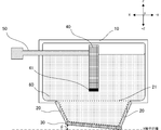
- the ultrasonic measurement device is formed of a main body portion 10, a cap portion 20, a silicon film 30, an ultrasonic probe 40, a drive mechanism 50, and water 60.
- the main body 10 is a rectangular parallelepiped having a rectangular shape on the bottom surface.
- the main body 10 contains the ultrasonic probe 40 and water 60 for transmitting ultrasonic waves inside the hollow shape.
- a long axis is arranged from the + X direction to the -X direction.
- the surface of the main body 10 having the base 20 is the lower surface, the surface opposite to the lower surface is the upper surface, the + Y direction side surface is the left side surface, the ⁇ Y direction side surface is the right side surface, and the + X direction side surface is the front surface.
- the side surface in the -X direction is referred to as the rear surface
- the plane composed of the X axis and the Y axis is referred to as the XY plane
- the plane composed of the X axis and the Z axis is referred to as the XZ plane
- the plane composed of the Y axis and the Z axis is referred to as the YZ plane.
- the lower surface and the upper surface are parallel to the XY plane
- the right side surface and the left side surface are parallel to the XZ plane.
- the main body 10 has a hollow shape inside.
- the base part 20 is columnar in appearance and has a hollow shape.
- the base part 20 is in contact with substantially the center of the lower surface of the main body part 10.
- the base portion 20 includes two straight line portions orthogonal to the Y axis and two curved line portions connecting the end portions of the two straight lines.
- the two straight portions have the same length.
- the curved lines are semicircular arcs that are convex in the + X direction and the ⁇ X direction, respectively.
- the length of the outer periphery of the cross section of the base part 20 is the longest on the lower surface side of the main body part and becomes shorter in the ⁇ Z direction. That is, the base portion 20 has a shape that is narrowed down in the ⁇ Z direction.
- the base part 20 penetrates the main body part 10 in the ⁇ Z direction through the hollow part 21. Since the base part 20 is integrated with the inside of the main body part 10 by the hollow-shaped part 21, the base part 20 holds the water 60 integrally with the main body part 10.
- the ⁇ Z direction surface of the base 20 is inclined at an angle ⁇ 1 with respect to the X axis as shown in FIG. 2, and at an angle ⁇ 1 with respect to the Y axis as shown in FIG. ing.
- the silicon film 30 is a film having the same planar shape as the surface in the ⁇ Z direction of the base part 20 and is made of a material that transmits ultrasonic waves.
- the silicon film 30 is provided so as to block the surface in the ⁇ Z direction of the main body portion 10 of the base portion 20. Therefore, the water 60 does not leak out from the main body 10 of the base part 20 and the surface in the ⁇ Z direction.
- the silicon film 30 is inclined at ⁇ 1 with respect to the X axis as shown in FIG. 2 because the surface in the ⁇ Z direction of the base portion 20 is inclined with respect to the X axis and the Y axis, and FIG. As shown in FIG. 2, the tilt is ⁇ 1 with respect to the Y axis.
- the ultrasonic probe 40 has a cylindrical shape. Further, the ⁇ Z side surface of the ultrasonic probe 40 is parallel to the lower surface of the main body 10. Further, the main body portion 10 has such a height that the ultrasonic probe 40 does not contact the upper surface inside the main body portion 10 and the silicon film 30.
- the transducer 41 is provided on the ⁇ Z side of the ultrasonic probe 40.
- the transducer 41 is electrically connected to a signal processing unit (not shown).
- the transducer 41 transmits and receives ultrasonic waves and outputs an electrical signal corresponding to the intensity of the received ultrasonic waves to a signal processing unit (not shown).
- the drive mechanism 50 passes through the rear surface of the main body 10 and is connected to the ultrasonic probe 40. Then, the drive mechanism 50 moves the ultrasonic probe in parallel along the X axis. With this configuration, the ultrasonic measurement apparatus can move the location to be measured with ultrasonic waves along the X axis.
- the ultrasonic wave emitted from the transducer 41 travels vertically inside the water 60 with respect to the lower surface of the main body 10 and travels in an inclined manner with respect to the silicon film 30.
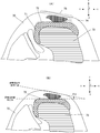
- FIG. 5 (A) and FIG. 6 (A) are diagrams showing the inside of the joint when the right knee is bent at 90 degrees or more.
- FIG. 5A is a cross-sectional view of the right knee as viewed from the inside to the outside.
- FIG. 6A is a view when the right knee is viewed from the trunk side toward the toe side.
- FIG. 5B and FIG. 6B are diagrams showing the relationship between the angle of the cartilage surface and the outer skin when the right knee is bent at 90 degrees or more.
- the + X side is the toe side
- the ⁇ X side is the trunk side.
- the + Y side is the inside of the right knee, and the ⁇ Y side is the outside of the right knee.
- the + Z side is the surface side of the knee
- the ⁇ Z side is the back side of the knee.
- the load portion 72 is a portion to which the load is most applied.
- the cartilage proximity skin 75 is a portion of the skin 70 that is close to the surface of the load portion 72 and has a substantially planar shape.
- the cartilage proximity outer skin 75 is inclined with respect to the surface of the load portion 72. Specifically, as shown in FIG. 5B, the cartilage proximity skin 75 is inclined at an angle ⁇ 2 with respect to the surface of the load portion 72 in the XZ plane. Also, as shown in FIG. 6B, the cartilage proximity skin 75 is inclined at an angle ⁇ 2 with respect to the surface of the load portion 72 in the YZ plane. Therefore, if ultrasonic waves are incident on the cartilage proximity skin 75 perpendicularly, the ultrasonic waves are not incident perpendicular to the surface of the load portion 72 and are not reflected perpendicularly on the surface of the load portion 72.
- FIG. 7 is a diagram showing the positions of the ultrasonic measurement device and the knee joint when the ultrasonic measurement device of the present invention is used in contact with the right knee bent at 120 degrees.
- FIG. 7 is a view of the right knee as viewed from the inside to the outside.
- the + X side is the toe side
- the ⁇ X side is the trunk side.
- the + Z side is the front side of the knee
- the ⁇ Z side is the back side of the knee.
- the silicon film 30 is used in parallel with the cartilage proximity skin 75 and in contact with the cartilage proximity skin 75 so as to form one plane.
- the lower surface of the main body 10 is parallel to the XY plane.
- the silicon film 30 and the cartilage proximity skin 75 are inclined at an angle ⁇ 1 with respect to the X axis (the lower surface of the main body 10).
- the silicon film 30 and the cartilage proximity skin 75 are inclined with respect to the surface of the load portion 72 at an angle ⁇ 2 in the XZ plane. Since the angle ⁇ 1 is set to be substantially the same value as the angle ⁇ 2, the surface of the load portion 72 is substantially parallel to the X axis (the lower surface of the main body portion 10).
- the measurer can make the lower surface of the main body portion 10 parallel to the surface of the load portion 72 in the XZ plane simply by applying the ultrasonic measurement device of the present invention to the cartilage proximity outer skin 75.
- the ultrasonic waves emitted from the transducer 41 sequentially pass through the silicon film 30, the cartilage proximity outer skin 75, and the soft tissue, and reach the load portion 72.
- the angle at which the ultrasonic wave travels is perpendicular to the surface of the load portion 72 because the lower surface of the main body portion 10 and the surface of the load portion 72 are parallel to each other.
- FIG. 8 is a view of the right knee and the ultrasonic measurement device shown in FIG. 7 as viewed from the trunk side of the subject toward the toe side.
- the ⁇ Y side is the outside of the right knee
- the + Y side is the inside of the right knee.
- the lower surface of the main body 10 and the silicon film 30 and the cartilage proximity skin 75 are inclined at an angle ⁇ 1 with respect to the Y axis (the lower surface of the main body 10).
- the silicon film 30 and the cartilage proximity outer skin 75 are inclined with respect to the surface of the load portion 72 at an angle ⁇ 2 in the YZ plane. Since the angle ⁇ 1 is set to be substantially the same value as the angle ⁇ 2, the surface of the load portion 72 is substantially parallel to the Y axis (the lower surface of the main body portion 10).
- the measurer can make the lower surface of the main body portion 10 parallel to the surface of the load portion 72 in the YZ plane simply by applying the ultrasonic measurement device of the present invention to the cartilage proximity outer skin 75.
- the ultrasonic wave emitted from the transducer 41 advances perpendicularly to the surface of the load portion 72 because the lower surface of the main body portion 10 and the surface of the load portion 72 are parallel to each other in the YZ plane.
- the ultrasonic measurement apparatus of the present invention can make the angle at which the ultrasonic wave travels perpendicular to the surface of the load portion 72 of the knee cartilage.
- the ultrasonic waves that reach the surface of the load portion 72 are reflected on the surface of the load portion 72 because the acoustic impedance of the soft tissue and the acoustic impedance of the knee joint cartilage 71 are different.
- the reflected wave is opposite to the traveling direction of the ultrasonic wave traveling from the transducer 41. Therefore, the reflected wave reaches the transducer 41 at the shortest distance from the surface of the load portion 72.
- the traveling angle of the ultrasonic wave with respect to the surface of the load part 72 is vertical as long as the surface of the load part 72 is flat even if the ultrasonic probe 40 is translated along the X axis by the drive mechanism 50. is there. Therefore, the ultrasonic measurement apparatus of the present invention can continuously measure the surface of the load portion 72 with the ultrasonic wave by translating the surface of the load portion 72 along the X axis by the drive mechanism 50.
- the angle ⁇ 1 and the angle ⁇ 1 of the ultrasonic measurement apparatus of the present invention completely coincide with the angle ⁇ 2 and the angle ⁇ 2, respectively.
- the angle ⁇ 2 and the angle ⁇ 2 vary depending on the subject.
- the measurer must finely adjust the angle of the ultrasonic probe 40 when measuring a subject whose angle ⁇ 2 or angle ⁇ 2 is significantly different from the average value of the subject.
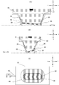
- an ultrasonic measurement apparatus provided with silicon rubber 80 as an elastic body will be described as follows. 9, the description of the same components as those in FIGS. 1 to 4 is omitted.
- FIG. 9A is a cross-sectional view of the ultrasonic measurement apparatus including the silicon rubber 80, taken along the XY plane
- FIG. 9B is a cross-sectional view taken along the YZ plane
- FIG. 9C is a bottom view. It is.
- the silicon rubber 80 is provided between the silicon film 30 and a portion of the base portion 20 that contacts the silicon film 30. As shown in FIG. 9C, the silicon rubber 80 has the same shape as the cross-sectional view of the base part 20.
- the silicon rubber 80 has a ring shape that is joined to the ⁇ Z side of the edge of the base part 20 along the edge of the base part 20.
- the silicon film 30 is bonded to the silicon rubber 80 on the side opposite to the edge of the base portion 20 of the silicon rubber 80 ( ⁇ Z side).
- the silicon rubber 80 is deformed by being pressed integrally with the ultrasonic measurement device by the measurer when the silicon film 30 is brought into contact with the cartilage proximity outer skin 75.
- the degree of deformation of the silicon rubber 80 is changed by an adjustment that the measurer makes the pressing force on the + X side stronger than the pressing force on the ⁇ X side.
- the ⁇ X side is Compared to the portion, the degree of compression along the Z axis increases. And, ⁇ 1 becomes larger than before increasing the pressing force.
- the measurer can finely adjust the angle ⁇ 1 and the angle ⁇ 1 by deforming the silicon rubber 80 by pressing. Further, when the base part 20 is made of metal, the silicon rubber 80 is compressed when pressed, thereby distributing local pressure on the surface of the living body, reducing damage to the surface of the living body, and reducing the burden on the subject. be able to.
- the ultrasonic measurement apparatus of the present invention including the silicon rubber 80 can finely adjust the angle ⁇ 1 and the angle ⁇ 1 according to the shape of the knee joint of the subject, and the angle ⁇ 2 and the angle ⁇ 2 can be adjusted by the subject. Even if they are different, the angle at which the ultrasonic wave travels can be made perpendicular to the surface of the load portion 72.
- the main body unit 10 and the base unit 20 are integrally configured, but a configuration in which the base unit 20 is replaced may be used.
- a screw hole is provided on the lower surface of the main body part 10, and the base part 20 and the silicon film 30 are attached to the main body part 10 with screws.
- the measurer can attach the base part 20 and the silicon film 30 of various shapes to the main body part 10 by joining the base part 20 and the main body part 10 with screws. Therefore, the measurer can replace the base portion 20 in accordance with the shape of the knee joint of the subject, and can make the ultrasonic traveling angle perpendicular to the surface of the load portion 72.
- the surface in the ⁇ Z direction of the base portion 20 is a planar shape composed of two straight lines and two curves, but is not limited to this shape.
- the traveling angle of the ultrasonic wave can be accurately perpendicular to the surface of the load part 72.
- the drive mechanism 50 moves the ultrasonic probe 40 in parallel along the X axis, but is not limited to the X axis direction.
- the drive mechanism 50 can move the ultrasonic probe 40 in parallel along the Y axis.
- the ultrasonic measurement device can continuously measure the planar shape of the surface of the load portion 72.
- the drive mechanism 50 can be moved in the Z-axis direction.
- the measurer adjusts the focal depth of the emitted ultrasonic wave by moving in the Z-axis direction even when the soft tissue is thick and the cartilage proximity skin 75 is far from the surface of the load portion 72. Ultrasound can be emitted appropriately.
- the scanning method by mechanical drive is shown, but it is also possible to arrange a large number of transducer elements on the array.
- the ultrasonic measurement apparatus according to the present invention can transmit and receive ultrasonic waves at a time even when a plurality of transducer devices are arranged in an array to constitute an ultrasonic probe without sequentially scanning by mechanical drive. Therefore, the measurer can measure the cartilage of the knee joint in a short time, and does not force the subject to measure for a long time.
- FIG. 10 is a diagram showing a flowchart of a method for measuring knee joint cartilage using the ultrasonic measurement apparatus of the present invention.
- the ultrasonic measurement apparatus receives an instruction to start measurement (s11)
- the ultrasonic probe 40 emits ultrasonic waves toward the cartilage of the knee joint (s12).
- the ultrasonic probe 40 receives the ultrasonic wave reflected by the load portion 72 (s13).
- the drive mechanism 50 moves the ultrasonic probe 40 (s15). And it returns to step s12 and it measures in a different position one by one.
- the ultrasonic measurement is terminated.
- the ultrasonic measurement method of the present invention it is possible to appropriately measure cartilage by causing ultrasonic waves to be incident perpendicularly to the surface of the load portion 72 of the knee joint cartilage 71 and sequentially scanning. it can.
Landscapes
- Life Sciences & Earth Sciences (AREA)
- Health & Medical Sciences (AREA)
- Physics & Mathematics (AREA)
- Engineering & Computer Science (AREA)
- Heart & Thoracic Surgery (AREA)
- Nuclear Medicine, Radiotherapy & Molecular Imaging (AREA)
- Pathology (AREA)
- Radiology & Medical Imaging (AREA)
- Veterinary Medicine (AREA)
- Biomedical Technology (AREA)
- Biophysics (AREA)
- Medical Informatics (AREA)
- Molecular Biology (AREA)
- Surgery (AREA)
- Animal Behavior & Ethology (AREA)
- General Health & Medical Sciences (AREA)
- Public Health (AREA)
- Acoustics & Sound (AREA)
- Ultra Sonic Daignosis Equipment (AREA)
Description
20…口金部
21…中空形状部分
30…シリコンフィルム
40…超音波プローブ
41…トランスデューサ
50…駆動機構
60…水
70…外皮
71…膝関節軟骨
72…荷重部
73…大腿骨
74…膝蓋骨
75…軟骨近接外皮
80…シリコンゴム
Claims (13)
- 中空体の本体部と、
前記本体部の一つの平面に設けられ、中空形状で、かつ前記本体部と中空形状部分を介して貫通される口金部と、
前記口金部のうち、前記本体部と反対側の面を、超音波を透過するように平面形状でふさぐ接触部と、
を備えた超音波測定器具であって、
前記接触部は、前記中空体の前記口金部が設けられた平面と平行な第1の軸、および前記第1の軸に直交し、かつ前記平面と平行な第2の軸に対し、傾斜していることを特徴とする超音波測定器具。 - 請求項1に記載の超音波測定器具であって、
前記本体部は、多面体形状であることを特徴とする超音波測定器具。 - 請求項1に記載の超音波測定器具であって、
前記本体部は、中空球体形状であることを特徴とする超音波測定器具。 - 請求項1乃至請求項3のいずれかに記載の超音波測定器具であって、
前記接触部が前記本体部の前記口金部が設けられた面に対し傾斜する角度は、膝関節の外皮表面に対する膝関節軟骨の表面が傾斜する角度に、対応することを特徴とする、超音波測定器具。 - 前記口金部における前記接触部と接する部分と前記接触部の間に、弾性体が設けられたことを特徴とする請求項1乃至請求項4のいずれかに記載の超音波測定器具。
- 前記弾性体は、シリコンゴムであることを特徴とする、請求項5に記載の超音波測定器具。
- 請求項1乃至請求項6のいずれかに記載の超音波測定器具であって、
前記口金部は、前記本体部の前記口金部が設けられた面と対向する面に向かって、絞り込まれた柱形状であることを特徴とする、超音波測定器具。 - 前記接触部は、直線部と曲線部を組み合わせた形状であることを特徴とする、請求項1乃至請求項7のいずれかに記載の超音波測定器具。
- 前記接触部は、シリコンフィルムであることを特徴とする、請求項1乃至請求項8のいずれかに記載の超音波測定器具。
- 請求項1乃至請求項9のいずれかに記載の超音波測定器具と、
前記接触部を通過する超音波を送受信する超音波プローブと、
前記超音波プローブを前記本体部の内部で駆動させる駆動機構と、を備えた超音波測定装置。 - 請求項10に記載の超音波測定装置であって、
前記駆動機構は、前記超音波プローブを前記本体部の前記口金部が設けられた面に平行に移動させることを特徴とする、超音波測定装置。 - 請求項10または請求項11のいずれかに記載の超音波測定装置であって、
前記駆動機構は、前記超音波プローブを前記本体部の前記口金部が設けられた面に垂直に移動させることを特徴とする、超音波測定装置。 - 請求項10乃至請求項12のいずれかに記載の超音波測定装置が、超音波を前記本体部の前記口金部が設けられた面に対し垂直に発射するステップと、
膝関節軟骨で反射し、かつ前記接触部を通過する超音波を受信するステップと、
を含む、膝関節軟骨の超音波測定方法。
Priority Applications (2)
| Application Number | Priority Date | Filing Date | Title |
|---|---|---|---|
| US14/415,301 US20150190117A1 (en) | 2012-07-17 | 2013-06-11 | Ultrasound measurement instrument and ultrasound measurement device |
| JP2014525756A JP5840780B2 (ja) | 2012-07-17 | 2013-06-11 | 超音波測定器具および超音波測定装置 |
Applications Claiming Priority (2)
| Application Number | Priority Date | Filing Date | Title |
|---|---|---|---|
| JP2012-158461 | 2012-07-17 | ||
| JP2012158461 | 2012-07-17 |
Publications (1)
| Publication Number | Publication Date |
|---|---|
| WO2014013816A1 true WO2014013816A1 (ja) | 2014-01-23 |
Family
ID=49948651
Family Applications (1)
| Application Number | Title | Priority Date | Filing Date |
|---|---|---|---|
| PCT/JP2013/066048 Ceased WO2014013816A1 (ja) | 2012-07-17 | 2013-06-11 | 超音波測定器具および超音波測定装置 |
Country Status (3)
| Country | Link |
|---|---|
| US (1) | US20150190117A1 (ja) |
| JP (1) | JP5840780B2 (ja) |
| WO (1) | WO2014013816A1 (ja) |
Cited By (2)
| Publication number | Priority date | Publication date | Assignee | Title |
|---|---|---|---|---|
| CN106102591A (zh) * | 2014-03-12 | 2016-11-09 | 古野电气株式会社 | 超声波诊断装置、以及超声波诊断方法 |
| JPWO2017094397A1 (ja) * | 2015-12-04 | 2018-09-20 | 古野電気株式会社 | 超音波解析装置、超音波解析方法及び超音波解析プログラム |
Families Citing this family (2)
| Publication number | Priority date | Publication date | Assignee | Title |
|---|---|---|---|---|
| JP2020203078A (ja) * | 2019-06-14 | 2020-12-24 | エコセンス | 粘弾性媒体の超音波パラメータを測定するための方法およびデバイス |
| US11850098B2 (en) | 2019-06-14 | 2023-12-26 | Echosens | Method and device for measuring an ultrasound parameter of a viscoelastic medium |
Citations (3)
| Publication number | Priority date | Publication date | Assignee | Title |
|---|---|---|---|---|
| JPS6294139A (ja) * | 1985-10-17 | 1987-04-30 | 旭光学工業株式会社 | 超音波診断装置の探触子 |
| JPH05261094A (ja) * | 1992-03-19 | 1993-10-12 | Hitachi Ltd | 頭蓋内動脈瘤位置検出装置 |
| JPH11104131A (ja) * | 1997-10-03 | 1999-04-20 | Matsushita Electric Ind Co Ltd | 超音波骨診断装置 |
Family Cites Families (7)
| Publication number | Priority date | Publication date | Assignee | Title |
|---|---|---|---|---|
| JPH02264641A (ja) * | 1989-04-04 | 1990-10-29 | Fuji Electric Co Ltd | 超音波探触子 |
| US6261231B1 (en) * | 1998-09-22 | 2001-07-17 | Dupont Pharmaceuticals Company | Hands-free ultrasound probe holder |
| US7080559B1 (en) * | 2005-03-08 | 2006-07-25 | Sensfab Pte Ltd | Transducer |
| US20070138911A1 (en) * | 2005-12-16 | 2007-06-21 | Impulse Devices Inc. | Tunable acoustic driver and cavitation chamber assembly |
| WO2009042644A2 (en) * | 2007-09-25 | 2009-04-02 | Perception Raisonnement Action En Medecine | Methods and apparatus for assisting cartilage diagnostic and therapeutic procedures |
| US20110144544A1 (en) * | 2009-12-15 | 2011-06-16 | General Electric Company | Ultrasound transducer assembly and methods of using |
| US20130144135A1 (en) * | 2011-08-02 | 2013-06-06 | Mohamed R. Mahfouz | Method and apparatus for three dimensional reconstruction of a joint using ultrasound |
-
2013
- 2013-06-11 JP JP2014525756A patent/JP5840780B2/ja not_active Expired - Fee Related
- 2013-06-11 WO PCT/JP2013/066048 patent/WO2014013816A1/ja not_active Ceased
- 2013-06-11 US US14/415,301 patent/US20150190117A1/en not_active Abandoned
Patent Citations (3)
| Publication number | Priority date | Publication date | Assignee | Title |
|---|---|---|---|---|
| JPS6294139A (ja) * | 1985-10-17 | 1987-04-30 | 旭光学工業株式会社 | 超音波診断装置の探触子 |
| JPH05261094A (ja) * | 1992-03-19 | 1993-10-12 | Hitachi Ltd | 頭蓋内動脈瘤位置検出装置 |
| JPH11104131A (ja) * | 1997-10-03 | 1999-04-20 | Matsushita Electric Ind Co Ltd | 超音波骨診断装置 |
Cited By (4)
| Publication number | Priority date | Publication date | Assignee | Title |
|---|---|---|---|---|
| CN106102591A (zh) * | 2014-03-12 | 2016-11-09 | 古野电气株式会社 | 超声波诊断装置、以及超声波诊断方法 |
| CN106102591B (zh) * | 2014-03-12 | 2019-03-26 | 古野电气株式会社 | 超声波诊断装置、以及超声波诊断方法 |
| US10568604B2 (en) | 2014-03-12 | 2020-02-25 | Furuno Electric Co., Ltd. | Method and device for ultrasonic diagnosis |
| JPWO2017094397A1 (ja) * | 2015-12-04 | 2018-09-20 | 古野電気株式会社 | 超音波解析装置、超音波解析方法及び超音波解析プログラム |
Also Published As
| Publication number | Publication date |
|---|---|
| JPWO2014013816A1 (ja) | 2016-06-30 |
| JP5840780B2 (ja) | 2016-01-06 |
| US20150190117A1 (en) | 2015-07-09 |
Similar Documents
| Publication | Publication Date | Title |
|---|---|---|
| KR101362378B1 (ko) | 초음파 진단장치용 프로브 | |
| CN103702615B (zh) | 超声波探头以及超声波诊断装置 | |
| US20100249598A1 (en) | Ultrasound probe with replaceable head portion | |
| US9089875B2 (en) | Ultrasound backing element, transducer and ultrasound probe including the same | |
| JP5840780B2 (ja) | 超音波測定器具および超音波測定装置 | |
| CN101152646A (zh) | 柔性超声换能器阵列及其应用装置 | |
| WO2021014773A1 (ja) | 超音波診断装置および超音波診断装置の制御方法 | |
| JP7387502B2 (ja) | 超音波自動スキャンシステム、超音波診断装置、超音波スキャン支援装置 | |
| KR20120084285A (ko) | 초음파 프로브 및 이의 사용 방법 | |
| JP2012523920A (ja) | ユニバーサルな複数開口の医療用超音波探触子 | |
| JP2016067925A (ja) | 臨床診断超音波イメージング用コンフォーマルインターフェイス | |
| KR20150095627A (ko) | 초음파 프로브 | |
| JP7122483B1 (ja) | Hifu照射装置用の超音波イメージングプローブおよび超音波画像表示装置 | |
| KR20160095791A (ko) | 초음파 프로브 및 이를 포함하는 초음파 장치 | |
| US10080550B2 (en) | Ultrasonic apparatus and control method for the same | |
| ES2741481T3 (es) | Dispositivo de sondeo de múltiples sensores ultrasónicos y su procedimiento de fabricación, método de controlar tal dispositivo y programa de ordenador correspondiente | |
| WO2019160118A1 (ja) | 超音波プローブ、及び、超音波プローブ用のプローブヘッド | |
| US8439841B2 (en) | Method of measuring the thickness of a biological tissue by ultrasounds and device for carrying out such method | |
| KR20110003057A (ko) | 초음파 프로브 및 초음파 진단장치 | |
| JP2017029209A (ja) | 超音波プローブ、及び超音波装置 | |
| JP2018153553A (ja) | 超音波撮像プローブ及び音波撮像プローブの操作方法 | |
| KR102099912B1 (ko) | 케이블의 자세 조절 장치 및 이를 포함한 초음파 프로브 | |
| US11911114B2 (en) | Ultrasonic probe and ultrasonic imaging apparatus including the same | |
| KR20190093977A (ko) | 초음파 프로브 | |
| JP6200246B2 (ja) | 探触子 |
Legal Events
| Date | Code | Title | Description |
|---|---|---|---|
| 121 | Ep: the epo has been informed by wipo that ep was designated in this application |
Ref document number: 13819620 Country of ref document: EP Kind code of ref document: A1 |
|
| ENP | Entry into the national phase |
Ref document number: 2014525756 Country of ref document: JP Kind code of ref document: A |
|
| WWE | Wipo information: entry into national phase |
Ref document number: 14415301 Country of ref document: US |
|
| NENP | Non-entry into the national phase |
Ref country code: DE |
|
| 122 | Ep: pct application non-entry in european phase |
Ref document number: 13819620 Country of ref document: EP Kind code of ref document: A1 |