WO2014010740A1 - Connector and connector connection structure - Google Patents
Connector and connector connection structure Download PDFInfo
- Publication number
- WO2014010740A1 WO2014010740A1 PCT/JP2013/069217 JP2013069217W WO2014010740A1 WO 2014010740 A1 WO2014010740 A1 WO 2014010740A1 JP 2013069217 W JP2013069217 W JP 2013069217W WO 2014010740 A1 WO2014010740 A1 WO 2014010740A1
- Authority
- WO
- WIPO (PCT)
- Prior art keywords
- electric wire
- housing
- connector
- insertion hole
- metal cover
- Prior art date
Links
Images


Classifications
-
- H—ELECTRICITY
- H01—ELECTRIC ELEMENTS
- H01R—ELECTRICALLY-CONDUCTIVE CONNECTIONS; STRUCTURAL ASSOCIATIONS OF A PLURALITY OF MUTUALLY-INSULATED ELECTRICAL CONNECTING ELEMENTS; COUPLING DEVICES; CURRENT COLLECTORS
- H01R13/00—Details of coupling devices of the kinds covered by groups H01R12/70 or H01R24/00 - H01R33/00
- H01R13/46—Bases; Cases
- H01R13/52—Dustproof, splashproof, drip-proof, waterproof, or flameproof cases
- H01R13/5202—Sealing means between parts of housing or between housing part and a wall, e.g. sealing rings
-
- H—ELECTRICITY
- H01—ELECTRIC ELEMENTS
- H01R—ELECTRICALLY-CONDUCTIVE CONNECTIONS; STRUCTURAL ASSOCIATIONS OF A PLURALITY OF MUTUALLY-INSULATED ELECTRICAL CONNECTING ELEMENTS; COUPLING DEVICES; CURRENT COLLECTORS
- H01R24/00—Two-part coupling devices, or either of their cooperating parts, characterised by their overall structure
- H01R24/28—Coupling parts carrying pins, blades or analogous contacts and secured only to wire or cable
-
- H—ELECTRICITY
- H01—ELECTRIC ELEMENTS
- H01R—ELECTRICALLY-CONDUCTIVE CONNECTIONS; STRUCTURAL ASSOCIATIONS OF A PLURALITY OF MUTUALLY-INSULATED ELECTRICAL CONNECTING ELEMENTS; COUPLING DEVICES; CURRENT COLLECTORS
- H01R13/00—Details of coupling devices of the kinds covered by groups H01R12/70 or H01R24/00 - H01R33/00
- H01R13/46—Bases; Cases
- H01R13/502—Bases; Cases composed of different pieces
- H01R13/506—Bases; Cases composed of different pieces assembled by snap action of the parts
-
- H—ELECTRICITY
- H01—ELECTRIC ELEMENTS
- H01R—ELECTRICALLY-CONDUCTIVE CONNECTIONS; STRUCTURAL ASSOCIATIONS OF A PLURALITY OF MUTUALLY-INSULATED ELECTRICAL CONNECTING ELEMENTS; COUPLING DEVICES; CURRENT COLLECTORS
- H01R13/00—Details of coupling devices of the kinds covered by groups H01R12/70 or H01R24/00 - H01R33/00
- H01R13/62—Means for facilitating engagement or disengagement of coupling parts or for holding them in engagement
- H01R13/622—Screw-ring or screw-casing
-
- H—ELECTRICITY
- H01—ELECTRIC ELEMENTS
- H01R—ELECTRICALLY-CONDUCTIVE CONNECTIONS; STRUCTURAL ASSOCIATIONS OF A PLURALITY OF MUTUALLY-INSULATED ELECTRICAL CONNECTING ELEMENTS; COUPLING DEVICES; CURRENT COLLECTORS
- H01R13/00—Details of coupling devices of the kinds covered by groups H01R12/70 or H01R24/00 - H01R33/00
- H01R13/648—Protective earth or shield arrangements on coupling devices, e.g. anti-static shielding
- H01R13/658—High frequency shielding arrangements, e.g. against EMI [Electro-Magnetic Interference] or EMP [Electro-Magnetic Pulse]
- H01R13/6591—Specific features or arrangements of connection of shield to conductive members
- H01R13/65912—Specific features or arrangements of connection of shield to conductive members for shielded multiconductor cable
-
- H—ELECTRICITY
- H01—ELECTRIC ELEMENTS
- H01R—ELECTRICALLY-CONDUCTIVE CONNECTIONS; STRUCTURAL ASSOCIATIONS OF A PLURALITY OF MUTUALLY-INSULATED ELECTRICAL CONNECTING ELEMENTS; COUPLING DEVICES; CURRENT COLLECTORS
- H01R13/00—Details of coupling devices of the kinds covered by groups H01R12/70 or H01R24/00 - H01R33/00
- H01R13/73—Means for mounting coupling parts to apparatus or structures, e.g. to a wall
- H01R13/74—Means for mounting coupling parts in openings of a panel
- H01R13/748—Means for mounting coupling parts in openings of a panel using one or more screws
-
- H—ELECTRICITY
- H01—ELECTRIC ELEMENTS
- H01R—ELECTRICALLY-CONDUCTIVE CONNECTIONS; STRUCTURAL ASSOCIATIONS OF A PLURALITY OF MUTUALLY-INSULATED ELECTRICAL CONNECTING ELEMENTS; COUPLING DEVICES; CURRENT COLLECTORS
- H01R2105/00—Three poles
-
- H—ELECTRICITY
- H01—ELECTRIC ELEMENTS
- H01R—ELECTRICALLY-CONDUCTIVE CONNECTIONS; STRUCTURAL ASSOCIATIONS OF A PLURALITY OF MUTUALLY-INSULATED ELECTRICAL CONNECTING ELEMENTS; COUPLING DEVICES; CURRENT COLLECTORS
- H01R2201/00—Connectors or connections adapted for particular applications
- H01R2201/26—Connectors or connections adapted for particular applications for vehicles
Definitions
- the present invention relates to a connector and a connector connection structure that can be reliably assembled with a simple configuration while reducing the number of parts.
- a connector for connecting high-current / high-voltage electric wires to the input / output terminals of electric devices such as motors mounted on electric vehicles it has waterproof and oil-proof properties, and it also has electromagnetic properties from the electromagnetic noise generated by the wires, and the surrounding electrons. Those having electromagnetic shielding properties to protect parts are known.
- Patent Document 1 a connector having a metal cover composed of a metal shell and a shield stopper, and housing and fixing a resin housing fitted with terminal fittings in a storage space inside the metal cover is provided. It is disclosed.
- a metal cover is configured by inserting a bolt into a bolt hole of a flange formed in each of a shell and a shield stopper and fastening both flanges, and the housing with a terminal fitting attached thereto, It is structured to be accommodated by being sandwiched between two metal parts (shell, shield stopper).
- Patent Document 1 As described above, two metal parts such as a shell and a shield stopper are required, resulting in an increase in the number of parts. Further, as described above, a process of fastening the shell and the shield stopper with the bolt is necessary, which causes a problem that the work is complicated.
- an object of the present invention is to provide a connector and a connector connection structure that can be reliably assembled with a simple configuration while reducing the number of parts.
- the present invention is a connector for connecting an electric wire to an electric device having an insertion opening for connecting an electric wire, and a terminal fitting for crimping a conductive wire exposed to the outside at a terminal portion of the electric wire, A housing for housing the terminal portion and the terminal fitting, and a cylindrical cover member for covering the housing and fixing the housing to the electric device, and the wire insertion hole for inserting the electric wire into the housing; A relative position between the housing and the cover member is regulated, and a position regulating means for regulating displacement by the electric wire inserted through the electric wire insertion hole is provided.
- the present invention is characterized in that it is a connector connection structure in which the electrical device and the electric wire are connected by inserting the connector having the above-described configuration into a predetermined insertion port provided in the electrical device.
- the cover member can be configured with a single component, and the number of components can be reduced. Furthermore, since the displacement of the position restricting means is restricted using the electric wire inserted through the electric wire insertion hole, the relative position can be restricted without providing a new bolt or the like. For this reason, the number of parts can be reduced, and complicated work such as bolt fastening can be omitted. As a result, assembly can be reliably performed with a simple configuration.
- the electric wire insertion hole can be brought into contact with the outer peripheral surface of the insulating coating of the electric wire.
- an electric wire can be made to contact
- the housing is made of a resin having flexibility, and a locking portion that restricts the relative position by locking an edge portion of the cover member is integrally formed in the housing.
- the locking portion constitutes the position restricting means, and the locking portion is disposed at an end portion in the insertion direction of the wire insertion hole, and is configured to be displaceable to the center side of the wire insertion hole. it can.
- the edge of the cover member can be easily and reliably locked only by the operation of pushing the lock portion into the cover member in a state of being displaced toward the center of the wire insertion hole. it can.
- the locking portion is displaced toward the center of the wire insertion hole and pushed into the cover member.
- the housing can be inserted into the cover member.
- locking part inserted in the inside of a cover member gets over the edge part of a cover member, it will release from the pressing force of a cover member, and will return to an original shape.
- it can be set as the locked state which controls the displacement of a latching
- the locking portion may have an inclined portion that is spaced away from the direction in which the locking portion can be displaced as the distance from the distal end increases.
- the housing has a plurality of the wire insertion holes that allow a plurality of the wires to be inserted, and the locking portion has a width that is substantially the same as a width in which the plurality of wires are arranged. And a rib that connects a portion that contacts the wire and a portion that contacts the edge of the cover member, corresponding to the position of the plurality of wires. .
- the engaging portion has substantially the same width as the width in which the plurality of electric wires are arranged, so that the other end side edge portion of the cover member can be more widely locked. For this reason, the relative position can be regulated more stably. And the pressing force received from the other end side edge part of an electric wire and a cover member can be firmly received by providing a rib corresponding to the position of an electric wire. For this reason, durability of a latching
- At least one pair of the position restricting means can be disposed so as to sandwich the electric wire.
- locking part can be set by the symmetrical positional relationship. For this reason, the relative position can be regulated with good balance without being biased.
- FIG. 1 shows a perspective view of the connector 1 as seen from one end side
- FIG. 2 shows a perspective view of the connector 1 as seen from the other end side
- FIG. 3 shows an exploded perspective view showing the housing 10 and the metal cover 11
- FIG. 4 is a rear view of the housing 10 as viewed from the other end side.
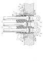
- FIG. 5 is a longitudinal sectional view of the connector 1
- FIG. 6 is a horizontal sectional view of the connector 1.
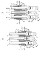
- 7 and 8 are explanatory diagrams for explaining the assembly of the connector 1 and the electric wire 2.
- the end on the terminal fitting 12 side is defined as one end
- the end on the opposite side of the electric wire 2 is defined as the other end.
- the boot 4 is shown in the permeation
- the connector 1 includes a flexible resin housing 10, a cylindrical metal cover 11 that covers the housing 10, and a plurality of connectors 1 exposed to the outside from one end side of the housing 10. (Here, three) terminal fittings 12 and a filling material filled in a plurality (three here) of filling spaces 10a individually formed on one end side of the housing 10 corresponding to the plurality of terminal fittings 12. 13.
- a plurality of (here, three) electric wires 2 are connected to the connector 1.
- the end portion of the electric wire 2 is crimped to the terminal fitting 12 of the connector 1 as will be described later. It is covered with a shield braid 3 formed by knitting a wire material subjected to metal plating into a tube shape, and a resin boot 4 indicated by a two-dot chain line in the figure. 3 to 6, illustration of the shield braid 3 and the boot 4 is omitted for convenience of illustration.
- the shield braid 3 is, for example, an electromagnetic shield member that absorbs electromagnetic waves emitted from the electric wires 2 when the electric wires 2 are for high current and high voltage, and the shield braid 3 shields the electromagnetic waves from being emitted to the outside. is doing.
- the shield braid 3 has an end located on the outer wall portion of the metal cover 11, and is attached to the metal cover 11 by a substantially annular predetermined fastener (not shown) formed corresponding to the shape of the metal cover 11. Fixed.
- the boot 4 is fixed to the metal cover 11 by a predetermined band member (not shown), and the boot 4 covers the ends of the electric wire 2, the metal cover 11, and the shield braid 3.
- the housing 10 has a plurality of filling spaces 10 a on one end side thereof, and grooves 10 b and 10 b for mounting O-rings 5 and 5 shown in FIG. 5 and FIG.
- the projections 10c and 10c on both sides for forming the concave groove 10b, and a pair of locking claws 10d disposed so as to sandwich the electric wire 2 are provided.
- the housing 10 has a plurality (three in this case) of wire insertion holes 10e corresponding to the number of the wires 2, as shown in FIGS.
- the locking claw 10d described above is disposed at the end portion of the electric wire insertion hole 10e in the insertion direction.
- the electric wire insertion hole 10 e communicates with the filling space 10 a and penetrates to the other end side of the housing 10, and the cross-sectional shape thereof is the same as the cross-sectional shape of the electric wire 2.
- the outer peripheral surface of the insulating coating 21 of the electric wire 2 is in contact with the inner wall portion of the electric wire insertion hole 10e with almost no gap.
- the position of the electric wire 2 is regulated to a predetermined position.
- the filling space 10a and the wire insertion hole 10e have different widths, and the filling space 10a has a larger width than the wire insertion hole 10e.
- step-difference part 10f is formed between the filling space 10a and the electric wire penetration hole 10e.
- the locking claw 10 d of the housing 10 has a free end at the other end, so that the wire 2 is not inserted into the wire insertion hole 10 e.
- the locking claw 10d can be displaced toward the center due to the flexibility of the housing 10.
- the locking claws 10d are provided in common to the plurality of electric wires 2 inserted through the electric wire insertion holes 10e, and have substantially the same width as the width in which these are arranged.
- the locking claw 10d extends in the arrangement direction of the electric wires 2 and is continuous with the electric wire insertion hole 10e, and stands on the other end side edge of the metal cover 11 upright from the electric wire abutting portion 10g. It has a metal cover abutting portion 10h that abuts, and further has a vertical rib 10i that connects the wire abutting portion 10g and the metal cover abutting portion 10h.
- the electric wire contact portion 10g is formed with an electric wire contact portion 10j formed in an arc shape corresponding to the position of the electric wire 2, as shown in FIGS. It is possible to contact the electric wire 2 inserted through the electric wire insertion hole 10e without any gap.
- each of the vertical ribs 10i has a locking claw as the distance from the tip of the locking claw 10d increases.
- 10d has the inclination part 10k spaced apart on the opposite side to the displaceable direction.
- the metal cover 11 has a cylindrical portion 11a having a substantially oval cross section, and a flange portion 11b that is upright from one end side of the cylindrical portion 11a and has a substantially rectangular shape.
- the flange portion 11b includes: Bolt holes 11c for inserting bolts 6 (see FIG. 6) are formed at the four corners.
- the other end side edge of the cylindrical portion 11 a of the metal cover 11 is locked by the locking claw 10 d, whereby the position of the other end side of the metal cover 11 is restricted.
- the flange portion 11b is in contact with the convex portion 10c of the housing 10, so that the position of one end side of the metal cover 11 is regulated. In this way, the relative positions of the housing 10 and the metal cover 11 are restricted by restricting the positions of the one end side and the other end side of the metal cover 11 with the convex portions 10c and the locking claws 10d.
- the displacement of the locking claw 10d toward the center side of the electric wire insertion hole 10e is restricted by the electric wire contact portion 10j contacting the electric wire 2 whose position is restricted by the electric wire insertion hole 10e without any gap.
- the locking state of the locking claw 10 d with respect to the metal cover 11 is held by the electric wire 2.
- the terminal fitting 12 integrally includes a connection terminal portion 12a, a wire barrel portion 12b, and an insulation barrel portion 12c.
- the conductor 2 is exposed by peeling off the insulation coating 21 at the terminal portion of the electric wire 2.
- the insulation coating 21 of the terminal portion is caulked by the insulation barrel portion 12 c and crimped.
- the conducting wire 22 is crimped and crimped by the wire barrel portion 12b.
- the terminal part of the electric wire 2 is crimped
- the filling space 10 a is disposed at a position corresponding to the crimping portion A (see FIG. 6) between the terminal portion of the electric wire 2 and the terminal fitting 12, thereby accommodating the crimping portion A in the housing 10. is doing. And in this filling space 10a, it fills with the filler 13 so that the crimping
- an epoxy resin, an acrylic resin, or silicon is used as the filler 13.
- the width of the filling space 10a is set to be substantially the same as the width of the insulation barrel portion 12c, so that the insulation barrel portion 12c is substantially at the step portion 10f. It fits without a gap.
- the connector 1 is for connecting a large current / high voltage electric wire 2 to an electric device M (see FIG. 6) such as a motor mounted on an electric vehicle, for example, and the case of the electric device M shown in FIG. Is provided with an insertion port Ma and a bolt hole Mb.
- the connector 1 is inserted into the insertion port Ma, the bolt 6 is inserted into the bolt hole 11c of the metal cover 11 and the bolt hole Mb of the electric device M, and both are fastened.
- the electric device M and the electric wire 2 are connected.
- the metal cover 11 is attached to the housing 10.
- the other end side of the housing 10 is inserted from one end side of the metal cover 11.
- the locking claw 10 d located on the other end side of the housing 10 is to be inserted into the metal cover 11
- the inclined portion 10 k of the vertical rib 10 i contacts the one end side edge portion of the metal cover 11 as shown in the figure. Touch.
- the locking claw 10d is pressed along the inclined portion 10k, so that the locking claw 10d is displaced toward the center of the wire insertion hole 10e as indicated by a thick arrow in the figure. It is supposed to be.
- the housing 10 can be inserted into the metal cover 11.
- the latching claw 10d inserted into the metal cover 11 reaches the other end of the metal cover 11 and gets over the edge of the other end of the metal cover 11, it is released from the pressing force of the metal cover 11. To return to the original shape. Thereby, as shown in FIG.7 (b), the latching claw 10d will be in the state which latched the edge part of the other end side of the metal cover 11, and this latching
- the relative position with the metal cover 11 is regulated. Thereby, the mounting
- the electric wire 2 from which the insulating coating 21 has been peeled and the conductive wire 22 is exposed is inserted into the electric wire insertion hole 10 e of the housing 10.
- the terminal portion is inserted from the other end side of the housing 10.
- the terminal portion of the electric wire 2 is crimped to the terminal fitting 12.
- the terminal part of the electric wire 2 inserted in the electric wire penetration hole 10e is pulled out to the exterior of the housing 10, and the conducting wire 22 and the insulation coating 21 of the said terminal part are respectively wire barrel parts. 12b and crimped by the insulation barrel 12c.
- the filler 13 is filled so as to cover the crimped portion A in the filling space 10a.
- bonded the terminal part of the electric wire 2 is completed by passing through each process shown in FIG. 7, FIG.
- the housing 10 and the metal cover are provided by the locking claw 10d that includes the cylindrical metal cover 11 that covers the housing 10 and whose displacement is restricted by the electric wire 2 that is inserted into the electric wire insertion hole 10e.
- the locking claw 10d that includes the cylindrical metal cover 11 that covers the housing 10 and whose displacement is restricted by the electric wire 2 that is inserted into the electric wire insertion hole 10e.
- the metal cover 11 can be configured with a single component, and the number of components can be reduced. Furthermore, since the displacement of the locking claw 10d is regulated using the electric wire 2 inserted into the electric wire insertion hole 10e, the relative position can be regulated without newly providing a bolt or the like. For this reason, the number of parts can be reduced, and complicated work such as bolt fastening can be omitted. As a result, assembly can be reliably performed with a simple configuration.
- the electric wire 2 can be brought into contact with the inner wall portion of the electric wire insertion hole 10e without any substantial gap. For this reason, the displacement restriction
- the housing 10 is made of resin, and a locking claw 10d formed integrally with the housing 10 is disposed at the end of the electric wire insertion hole 10e in the insertion direction, and can be displaced toward the center of the electric wire insertion hole 10e.
- the edge of the other end of the metal cover 11 can be easily and reliably moved only by pushing the locking claw 10d into the center of the wire insertion hole 10e and pushing it into the metal cover 11. Can be locked.
- the locking claw 10d is displaced toward the center of the wire insertion hole 10e so that the metal cover 11 is inserted. If pushed into the inside, the housing 10 can be inserted into the metal cover 11. And if the latching claw 10d inserted in the inside of the metal cover 11 gets over the other end side edge part of the metal cover 11, it will release from the pressing force of the metal cover 11, and will return to the original shape. To do. Thereby, the other end side edge part of the metal cover 11 can be latched by the latching claw 10d.
- the latching claw 10d has an inclined portion 10k that is spaced away from the direction in which the latching claw 10d can be displaced as it moves away from the tip
- the electric wire Even if an external force is not applied toward the center of the insertion hole 10e, the locking claw 10d can be displaced toward the center of the wire insertion hole 10e by pressing the locking claw 10d along the inclined portion 10k. it can. For this reason, the operation
- the latching claw 10d has substantially the same width as the width in which the plurality of wires 2 are arranged, the other end side edge of the metal cover 11 can be latched more widely. For this reason, the relative position can be regulated more stably. And the pressing force received from the other end side edge part of the electric wire 2 and the metal cover 11 by providing the vertical rib 10i which connects the electric wire contact part 10g and the metal cover contact part 10h corresponding to the position of the electric wire 2 Can be taken firmly. For this reason, durability of 10 n of latching claws can be improved.
- the locking portion by the locking claws 10d can be set in a symmetrical positional relationship. For this reason, the relative position can be regulated with good balance without being biased.
- the connector 1 has the electric wire insertion hole 10e with which the outer peripheral surface of the insulation coating 21 of the electric wire 2 abuts, and the filling space 10a communicating with the electric wire insertion hole 10e, and in the filling space 10a.
- the crimping portion A can be reliably covered without using a molding method. Furthermore, the electric wire 2 can be brought into contact with the inner wall portion of the electric wire insertion hole 10e with almost no gap by the electric wire insertion hole 10e with which the outer peripheral surface of the insulating coating 21 abuts. For this reason, the position of the electric wire 2 inserted through the electric wire insertion hole 10e can be restricted, and as a result, the position of the crimping portion A in the filling space 10a can be restricted. In this case, since the position of the crimping part A can be regulated without providing a special structure, the structure of the connector 1 can be simplified.
- step portion 10f corresponding to the width of the electric wire 2 and the crimping portion A (here, the largest insulation barrel portion 12c) between the filling space 10a and the electric wire insertion hole 10e, Even if a special structure is not newly provided, positioning of the crimping portion A in the insertion direction of the electric wire 2 can be performed using the step portion 10f formed for the electric wire 2 and the crimping portion A. For this reason, the position in the filling space 10a of the crimping
- the crimping portion A can be reliably covered with the filling material 13.
- the filling space becomes complicated and has a large capacity. There is a concern that bubbles are partially formed during filling.
- the filling spaces 10a are individually formed corresponding to the wire insertion holes 10e, the capacity can be reduced while simplifying the shape of each filling space 10a.
- the crimping part A can be reliably covered with the filler 13 without forming bubbles in 10a.
- a concave groove or a convex portion may be provided in one of the housing 10 and the metal cover 11, and a convex portion or a concave groove that can be fitted to the concave groove or the convex portion may be provided in the other.
- a pair of the locking claws 10d are provided so as to sandwich the electric wire 2, the present invention is not necessarily limited thereto.
- a pair of locking claws (locking portions) facing each other in a direction orthogonal to the direction in which the locking claws 10d are opposed may be additionally provided.
- Stop portions (locking claws) may be provided at predetermined intervals in the circumferential direction of the other end side edge portion of the housing 10.
- the cover member of the present embodiment corresponds to the metal cover 11.
- the position restricting means and the locking portion correspond to the locking claw 10d
- the portion that contacts the wire corresponds to the wire contact portion 10g
- corresponds to the metal cover contact part 10h, it is not limited to the said embodiment.
Landscapes
- Details Of Connecting Devices For Male And Female Coupling (AREA)
- Connector Housings Or Holding Contact Members (AREA)
Abstract
The present invention is provided with: a terminal fitting (12) that crimps a conductor wire (22) exposed to the outside at the terminus of a conductor wire (2); a housing (10) that houses the terminus of the conductor wire (2) and the terminal fitting (12); and a tubular metal cover (11) that covers the housing (10) and affixes same to an electrical apparatus (M). The housing (10) is provided with: a conductor wire threading hole (10e) into which the conductor wire (2) is threaded; and a locking claw (10d) that, as a position regulation means, regulates the relative position of the housing (10) and the metal cover (11), and of which the displacement is regulated by the conductor wire (2) threaded into the conductor wire threading hole (10e).
Description
本発明は、部品点数の削減を図りつつ、簡素な構成で確実に組付けが行えるコネクタ及びコネクタの接続構造に関するものである。
The present invention relates to a connector and a connector connection structure that can be reliably assembled with a simple configuration while reducing the number of parts.
従来、電気自動車に搭載したモータなどの電気機器の入出力端子に、大電流・高電圧用の電線を接続するコネクタとして、防水性及び防油性を備えるとともに、電線が発する電磁波ノイズから周辺の電子部品を保護すべく電磁波シールド性を備えたものが知られている。
Conventionally, as a connector for connecting high-current / high-voltage electric wires to the input / output terminals of electric devices such as motors mounted on electric vehicles, it has waterproof and oil-proof properties, and it also has electromagnetic properties from the electromagnetic noise generated by the wires, and the surrounding electrons. Those having electromagnetic shielding properties to protect parts are known.
このうち、下記特許文献1では、金属製のシェル及びシールドストッパーからなる金属製カバーを備え、該金属製カバー内部の収納空間に、端子金具を装着した樹脂製のハウジングを収納、固定したコネクタが開示されている。
Among these, in the following Patent Document 1, a connector having a metal cover composed of a metal shell and a shield stopper, and housing and fixing a resin housing fitted with terminal fittings in a storage space inside the metal cover is provided. It is disclosed.
下記特許文献1では、シェル及びシールドストッパーにそれぞれ形成したフランジのボルト孔にボルトを挿通して両フランジを締結することによって、金属製カバーを構成しており、端子金具を装着した前記ハウジングを、2つの金属部品(シェル、シールドストッパー)で挟み込むことによって収納する構造となっている。
In the following Patent Document 1, a metal cover is configured by inserting a bolt into a bolt hole of a flange formed in each of a shell and a shield stopper and fastening both flanges, and the housing with a terminal fitting attached thereto, It is structured to be accommodated by being sandwiched between two metal parts (shell, shield stopper).
しかしながら、下記特許文献1では、前述のように、シェル及びシールドストッパーといった2つの金属部品が必要となり、その結果、部品点数の増大を招くという問題があった。さらに、前述のように、シェルとシールドストッパーとをボルト締結する工程が必要となるため、作業の煩雑化を招くという問題もあった。
However, in Patent Document 1 below, as described above, two metal parts such as a shell and a shield stopper are required, resulting in an increase in the number of parts. Further, as described above, a process of fastening the shell and the shield stopper with the bolt is necessary, which causes a problem that the work is complicated.
そこでこの発明は、部品点数の削減を図りつつ、簡素な構成で確実に組付けが行えるコネクタ及びコネクタの接続構造を提供することを目的とする。
Accordingly, an object of the present invention is to provide a connector and a connector connection structure that can be reliably assembled with a simple configuration while reducing the number of parts.
本発明は、電線接続用の挿入口を備えた電気機器に対して、電線を接続するコネクタであって、前記電線の端末部にて外部に露出する導線を圧着した端子金具と、前記電線の端末部及び前記端子金具を収容するハウジングと、該ハウジングを覆うとともに、これを前記電気機器に固定する筒状のカバー部材とを備え、前記ハウジングに、前記電線を挿通する電線挿通孔と、前記ハウジングと前記カバー部材との相対位置を規制するとともに、前記電線挿通孔に挿通した前記電線により変位が規制される位置規制手段とを設けたことを特徴とする。また、この発明は、上記構成を備えたコネクタを、電気機器に備えた所定の挿入口に挿入することにより、前記電気機器と電線とを接続したコネクタの接続構造であることを特徴とする。
The present invention is a connector for connecting an electric wire to an electric device having an insertion opening for connecting an electric wire, and a terminal fitting for crimping a conductive wire exposed to the outside at a terminal portion of the electric wire, A housing for housing the terminal portion and the terminal fitting, and a cylindrical cover member for covering the housing and fixing the housing to the electric device, and the wire insertion hole for inserting the electric wire into the housing; A relative position between the housing and the cover member is regulated, and a position regulating means for regulating displacement by the electric wire inserted through the electric wire insertion hole is provided. In addition, the present invention is characterized in that it is a connector connection structure in which the electrical device and the electric wire are connected by inserting the connector having the above-described configuration into a predetermined insertion port provided in the electrical device.
上記構成によれば、部品点数の削減を図りつつ、簡素な構成で確実に組付けが行える。
According to the above configuration, it is possible to reliably assemble with a simple configuration while reducing the number of parts.
詳しくは、カバー部材を筒状に形成することによって、単一の部品でカバー部材を構成することができ、部品点数の削減を図ることができる。さらに、電線挿通孔に挿通する電線を利用して位置規制手段の変位を規制するため、ボルトなどを新たに設けなくても、前記相対位置を規制することができる。このため、部品点数の削減を図ることができるとともに、ボルト締結などの煩雑な作業を省略することができ、その結果、簡素な構成で確実に組付けを行うことができる。
Specifically, by forming the cover member in a cylindrical shape, the cover member can be configured with a single component, and the number of components can be reduced. Furthermore, since the displacement of the position restricting means is restricted using the electric wire inserted through the electric wire insertion hole, the relative position can be restricted without providing a new bolt or the like. For this reason, the number of parts can be reduced, and complicated work such as bolt fastening can be omitted. As a result, assembly can be reliably performed with a simple configuration.
この発明の態様として、前記電線挿通孔を、前記電線の絶縁被覆の外周面に当接させることができる。
上記構成によれば、電線を、電線挿通孔の内壁部に略隙間なく当接させることができる。このため、電線による位置規制手段の変位規制をより確実に行うことができる。 As an aspect of the present invention, the electric wire insertion hole can be brought into contact with the outer peripheral surface of the insulating coating of the electric wire.
According to the said structure, an electric wire can be made to contact | abut to the inner wall part of an electric wire penetration hole without a substantially clearance gap. For this reason, the displacement restriction | limiting of the position control means by an electric wire can be performed more reliably.
この発明の態様として、前記ハウジングを、可撓性を有する樹脂製とし、該ハウジングには、前記カバー部材の縁部を係止することで前記相対位置を規制する係止部を一体形成して、該係止部により前記位置規制手段を構成するとともに、前記係止部を、前記電線挿通孔の挿通方向端部に配設し、該電線挿通孔の中心側に変位可能に構成することができる。
As an aspect of the present invention, the housing is made of a resin having flexibility, and a locking portion that restricts the relative position by locking an edge portion of the cover member is integrally formed in the housing. The locking portion constitutes the position restricting means, and the locking portion is disposed at an end portion in the insertion direction of the wire insertion hole, and is configured to be displaceable to the center side of the wire insertion hole. it can.
上記構成によれば、係止部を電線挿通孔の中心側に変位させた状態にしてカバー部材の内部に押し込むという作業のみにより、カバー部材の縁部を容易に且つ確実に係止することができる。
詳しくは、カバー部材をハウジングに装着すべく、ハウジングをカバー部材の内部に挿通する際、係止部を電線挿通孔の中心側に変位させた状態にしてカバー部材の内部に押し込むようにすれば、ハウジングをカバー部材の内部に挿通させることができる。そして、カバー部材の内部に挿通された係止部は、カバー部材の縁部を乗越えると、カバー部材の押圧力から解放されることにより、元の形状に戻ろうとする。これにより、カバー部材の縁部を係止部で係止することができる。この場合、カバー部材の縁部を係止部により係止した状態で電線を電線挿通孔に挿通することで、係止部の変位を規制するロック状態とすることができる。 According to the above configuration, the edge of the cover member can be easily and reliably locked only by the operation of pushing the lock portion into the cover member in a state of being displaced toward the center of the wire insertion hole. it can.
Specifically, in order to attach the cover member to the housing, when the housing is inserted into the cover member, the locking portion is displaced toward the center of the wire insertion hole and pushed into the cover member. The housing can be inserted into the cover member. And if the latching | locking part inserted in the inside of a cover member gets over the edge part of a cover member, it will release from the pressing force of a cover member, and will return to an original shape. Thereby, the edge part of a cover member can be latched by a latching | locking part. In this case, it can be set as the locked state which controls the displacement of a latching | locking part by inserting an electric wire in an electric wire penetration hole in the state which latched the edge of the cover member with the latching | locking part.
またこの発明の態様として、前記係止部は、先端から離れるにつれて該係止部が変位可能な方向と反対側に離間する傾斜部を有することができる。
上記構成によれば、ハウジングをカバー部材の内部に挿通する際、電線挿通孔の中心に向かって外力を加えなくても、傾斜部に沿って係止部が押圧されることにより、係止部を電線挿通孔の中心に向かって変位させることができる。このため、カバー部材をハウジングに装着する作業をより簡素化することができる。 Further, as an aspect of the present invention, the locking portion may have an inclined portion that is spaced away from the direction in which the locking portion can be displaced as the distance from the distal end increases.
According to the above configuration, when the housing is inserted into the cover member, the engaging portion is pressed along the inclined portion without applying an external force toward the center of the wire insertion hole. Can be displaced toward the center of the wire insertion hole. For this reason, the operation | work which mounts a cover member in a housing can be simplified more.
またこの発明の態様として、前記ハウジングは、複数本の前記電線の挿通を許容する前記電線挿通孔を複数有するとともに、前記係止部は、前記複数本の電線が配列される幅と略同じ幅を有し、前記係止部には、前記電線に当接する部位と、前記カバー部材の縁部に当接する部位とを接続するリブを、前記複数の電線の位置に対応して設けることができる。
Further, as an aspect of the present invention, the housing has a plurality of the wire insertion holes that allow a plurality of the wires to be inserted, and the locking portion has a width that is substantially the same as a width in which the plurality of wires are arranged. And a rib that connects a portion that contacts the wire and a portion that contacts the edge of the cover member, corresponding to the position of the plurality of wires. .
上記構成によれば、係止部が、複数本の電線が配列される幅と略同じ幅を有することにより、カバー部材の他端側縁部をより幅広く係止することができる。このため、前記相対位置をより安定的に規制することができる。そして、リブを電線の位置に対応して設けることにより、電線及びカバー部材の他端側縁部から受ける押圧力を強固に受け止めることができる。このため、係止部の耐久性を向上させることができる。
According to the above configuration, the engaging portion has substantially the same width as the width in which the plurality of electric wires are arranged, so that the other end side edge portion of the cover member can be more widely locked. For this reason, the relative position can be regulated more stably. And the pressing force received from the other end side edge part of an electric wire and a cover member can be firmly received by providing a rib corresponding to the position of an electric wire. For this reason, durability of a latching | locking part can be improved.
またこの発明の態様として、前記位置規制手段を、前記電線を挟むように少なくとも一対配設することができる。
上記構成によれば、係止部による係止部位を対称の位置関係で設定することができる。このため、前記相対位置を偏りなくバランス良く規制することができる。 As an aspect of the present invention, at least one pair of the position restricting means can be disposed so as to sandwich the electric wire.
According to the said structure, the latching site | part by a latching | locking part can be set by the symmetrical positional relationship. For this reason, the relative position can be regulated with good balance without being biased.
この発明によれば、部品点数の削減を図りつつ、簡素な構成で確実に組付けが行えるコネクタ及びコネクタの接続構造を提供することができる。
According to the present invention, it is possible to provide a connector and a connector connection structure that can be reliably assembled with a simple configuration while reducing the number of parts.
この発明の一実施形態を以下図面とともに説明する。
図1はコネクタ1を一端側から見た斜視図を示し、図2はコネクタ1を他端側から見た斜視図を示し、図3はハウジング10及びメタルカバー11を示す分解斜視図を示し、図4は、ハウジング10を他端側から見た背面図を示す。図5はコネクタ1の縦断面図を示し、図6はコネクタ1の水平方向断面図を示す。図7、図8は、コネクタ1及び電線2の組付けを説明するための説明図を示す。なお、本明細書では、端子金具12側の端部を一端側、その反対側の電線2側の端部を他端側と定義する。また、図1、図2において、ブーツ4は、図示の便宜上、二点鎖線により透過状態で示す。 An embodiment of the present invention will be described below with reference to the drawings.
1 shows a perspective view of theconnector 1 as seen from one end side, FIG. 2 shows a perspective view of the connector 1 as seen from the other end side, FIG. 3 shows an exploded perspective view showing the housing 10 and the metal cover 11, FIG. 4 is a rear view of the housing 10 as viewed from the other end side. FIG. 5 is a longitudinal sectional view of the connector 1, and FIG. 6 is a horizontal sectional view of the connector 1. 7 and 8 are explanatory diagrams for explaining the assembly of the connector 1 and the electric wire 2. In the present specification, the end on the terminal fitting 12 side is defined as one end, and the end on the opposite side of the electric wire 2 is defined as the other end. Moreover, in FIG. 1, FIG. 2, the boot 4 is shown in the permeation | transmission state by the dashed-two dotted line for convenience of illustration.
図1はコネクタ1を一端側から見た斜視図を示し、図2はコネクタ1を他端側から見た斜視図を示し、図3はハウジング10及びメタルカバー11を示す分解斜視図を示し、図4は、ハウジング10を他端側から見た背面図を示す。図5はコネクタ1の縦断面図を示し、図6はコネクタ1の水平方向断面図を示す。図7、図8は、コネクタ1及び電線2の組付けを説明するための説明図を示す。なお、本明細書では、端子金具12側の端部を一端側、その反対側の電線2側の端部を他端側と定義する。また、図1、図2において、ブーツ4は、図示の便宜上、二点鎖線により透過状態で示す。 An embodiment of the present invention will be described below with reference to the drawings.
1 shows a perspective view of the
コネクタ1は、図1~図6に示すように、可撓性を有する樹脂製のハウジング10と、該ハウジング10を覆う筒状のメタルカバー11と、ハウジング10の一端側から外部に露出する複数(ここでは3つ)の端子金具12と、複数の端子金具12に対応して、ハウジング10の一端側に個別に形成した複数(ここでは3つ)の充填空間10a内に充填された充填材13とにより構成している。
As shown in FIGS. 1 to 6, the connector 1 includes a flexible resin housing 10, a cylindrical metal cover 11 that covers the housing 10, and a plurality of connectors 1 exposed to the outside from one end side of the housing 10. (Here, three) terminal fittings 12 and a filling material filled in a plurality (three here) of filling spaces 10a individually formed on one end side of the housing 10 corresponding to the plurality of terminal fittings 12. 13.
コネクタ1には、図1、図2、図5、図6に示すように、複数本(ここでは3本)の電線2を接続している。電線2は、その端末部がそれぞれ後述するようにコネクタ1の端子金具12に圧着されるとともに、コネクタ1の外部では、図1、図2に示すように、金属製の素線または樹脂製の線材に金属メッキ加工を施したものをチューブ状に編んで構成したシールド編組3、及び図中二点鎖線で示す樹脂製のブーツ4により覆われている。なお、図3~図6においては、図示の便宜上、シールド編組3、ブーツ4の図示を省略している。
As shown in FIGS. 1, 2, 5, and 6, a plurality of (here, three) electric wires 2 are connected to the connector 1. As shown in FIGS. 1 and 2, the end portion of the electric wire 2 is crimped to the terminal fitting 12 of the connector 1 as will be described later. It is covered with a shield braid 3 formed by knitting a wire material subjected to metal plating into a tube shape, and a resin boot 4 indicated by a two-dot chain line in the figure. 3 to 6, illustration of the shield braid 3 and the boot 4 is omitted for convenience of illustration.
シールド編組3は、例えば、電線2が大電流・高電圧用である場合に電線2から発せられる電磁波を吸収する電磁シールド部材であり、このシールド編組3により、電磁波が外部に放出されないようにシールドしている。
The shield braid 3 is, for example, an electromagnetic shield member that absorbs electromagnetic waves emitted from the electric wires 2 when the electric wires 2 are for high current and high voltage, and the shield braid 3 shields the electromagnetic waves from being emitted to the outside. is doing.
また、シールド編組3は、その端部が、メタルカバー11の外壁部に位置しており、該メタルカバー11の形状に対応して形成した略環状の図示しない所定の留め具によりメタルカバー11に固定される。また、ブーツ4は、図示しない所定のバンド部材により、メタルカバー11に固定され、このブーツ4によって、電線2、メタルカバー11、及びシールド編組3の端部を覆っている。
The shield braid 3 has an end located on the outer wall portion of the metal cover 11, and is attached to the metal cover 11 by a substantially annular predetermined fastener (not shown) formed corresponding to the shape of the metal cover 11. Fixed. The boot 4 is fixed to the metal cover 11 by a predetermined band member (not shown), and the boot 4 covers the ends of the electric wire 2, the metal cover 11, and the shield braid 3.
コネクタ1のうち、ハウジング10は、その一端側に複数の充填空間10aを有するとともに、外壁部には、図5、図6に示すOリング5,5を装着するための凹溝10b,10bと、凹溝10bを形成するための両側の凸部10c,10cと、電線2を挟むように配設した一対の係止爪10dとを有している。
Among the connectors 1, the housing 10 has a plurality of filling spaces 10 a on one end side thereof, and grooves 10 b and 10 b for mounting O- rings 5 and 5 shown in FIG. 5 and FIG. The projections 10c and 10c on both sides for forming the concave groove 10b, and a pair of locking claws 10d disposed so as to sandwich the electric wire 2 are provided.
さらに、ハウジング10は、その内部において、図3~図6に示すように、電線2の挿通を許容する電線挿通孔10eを電線2の本数に対応して複数(ここでは3つ)有し、上述した係止爪10dを、電線挿通孔10eの挿通方向端部に配設している。電線挿通孔10eは、充填空間10aに連通してハウジング10の他端側まで貫通しており、その断面形状は、電線2の断面形状と同形状をなしている。このため、電線挿通孔10eに電線2を挿通した状態では、電線2の絶縁被覆21の外周面が電線挿通孔10eの内壁部に略隙間なく当接した状態となり、これによって、ハウジング10内における電線2の位置が所定位置に規制されるようになっている。
Further, as shown in FIGS. 3 to 6, the housing 10 has a plurality (three in this case) of wire insertion holes 10e corresponding to the number of the wires 2, as shown in FIGS. The locking claw 10d described above is disposed at the end portion of the electric wire insertion hole 10e in the insertion direction. The electric wire insertion hole 10 e communicates with the filling space 10 a and penetrates to the other end side of the housing 10, and the cross-sectional shape thereof is the same as the cross-sectional shape of the electric wire 2. For this reason, in the state where the electric wire 2 is inserted into the electric wire insertion hole 10e, the outer peripheral surface of the insulating coating 21 of the electric wire 2 is in contact with the inner wall portion of the electric wire insertion hole 10e with almost no gap. The position of the electric wire 2 is regulated to a predetermined position.
また、充填空間10a、電線挿通孔10eは、図6に示すように、互いにその幅が異なっており、充填空間10aが電線挿通孔10eよりも大きな幅を有している。これにより、充填空間10aと電線挿通孔10eとの間には段差部10fを形成している。
Further, as shown in FIG. 6, the filling space 10a and the wire insertion hole 10e have different widths, and the filling space 10a has a larger width than the wire insertion hole 10e. Thereby, the level | step-difference part 10f is formed between the filling space 10a and the electric wire penetration hole 10e.
ハウジング10の係止爪10dは、図1~図5に示すように、他端側の端部が自由端になっていることから、電線2を電線挿通孔10eに挿通していない状態において、係止爪10dを電線挿通孔10eの中心側へ押圧すると、係止爪10dは、ハウジング10の可撓性により前記中心側に変位することが可能になっている。
As shown in FIGS. 1 to 5, the locking claw 10 d of the housing 10 has a free end at the other end, so that the wire 2 is not inserted into the wire insertion hole 10 e. When the locking claw 10d is pressed toward the center of the electric wire insertion hole 10e, the locking claw 10d can be displaced toward the center due to the flexibility of the housing 10.
また、係止爪10dは、電線挿通孔10eに挿通した複数の電線2に共通して設けており、これらが配列される幅と略同じ幅を有している。そして、係止爪10dは、電線2の配列方向に延びて電線挿通孔10eに連続する電線当接部10gと、該電線当接部10gから直立してメタルカバー11の他端側縁部に当接するメタルカバー当接部10hとを有し、さらには、電線当接部10gとメタルカバー当接部10hとを接続する縦リブ10iを有している。
Further, the locking claws 10d are provided in common to the plurality of electric wires 2 inserted through the electric wire insertion holes 10e, and have substantially the same width as the width in which these are arranged. The locking claw 10d extends in the arrangement direction of the electric wires 2 and is continuous with the electric wire insertion hole 10e, and stands on the other end side edge of the metal cover 11 upright from the electric wire abutting portion 10g. It has a metal cover abutting portion 10h that abuts, and further has a vertical rib 10i that connects the wire abutting portion 10g and the metal cover abutting portion 10h.
このうち、電線当接部10gは、特に、図2~図4に示すように、電線2の位置に対応して、円弧状に形成した電線当接部10jを形成しており、これによって、電線挿通孔10eに挿通された電線2と隙間なく当接することが可能になっている。
Among these, the electric wire contact portion 10g is formed with an electric wire contact portion 10j formed in an arc shape corresponding to the position of the electric wire 2, as shown in FIGS. It is possible to contact the electric wire 2 inserted through the electric wire insertion hole 10e without any gap.
また、縦リブ10iは、電線2の位置に対応して複数(ここでは3つ)配設しており、この縦リブ10iには、いずれも係止爪10dの先端から離れるにつれて該係止爪10dが変位可能な方向と反対側に離間する傾斜部10kを有している。
Further, a plurality (three in this case) of the vertical ribs 10i are arranged corresponding to the positions of the electric wires 2, and each of the vertical ribs 10i has a locking claw as the distance from the tip of the locking claw 10d increases. 10d has the inclination part 10k spaced apart on the opposite side to the displaceable direction.
一方、メタルカバー11は、断面略楕円形をなす筒状部11aと、筒状部11aの一端側から直立して略矩形状をなすフランジ部11bとを有し、該フランジ部11bには、その四隅にボルト6(図6参照)を挿通するためのボルト孔11cを穿設している。
On the other hand, the metal cover 11 has a cylindrical portion 11a having a substantially oval cross section, and a flange portion 11b that is upright from one end side of the cylindrical portion 11a and has a substantially rectangular shape. The flange portion 11b includes: Bolt holes 11c for inserting bolts 6 (see FIG. 6) are formed at the four corners.
コネクタ1では、メタルカバー11の筒状部11aの他端側縁部が、係止爪10dに係止されることにより、メタルカバー11の他端側の位置が規制される一方、メタルカバー11のフランジ部11bが、ハウジング10の凸部10cと当接することにより、メタルカバー11の一端側の位置が規制されている。このように、メタルカバー11の一端側、他端側の位置を凸部10c、係止爪10dで規制することにより、ハウジング10とメタルカバー11との相対位置を規制している。
In the connector 1, the other end side edge of the cylindrical portion 11 a of the metal cover 11 is locked by the locking claw 10 d, whereby the position of the other end side of the metal cover 11 is restricted. The flange portion 11b is in contact with the convex portion 10c of the housing 10, so that the position of one end side of the metal cover 11 is regulated. In this way, the relative positions of the housing 10 and the metal cover 11 are restricted by restricting the positions of the one end side and the other end side of the metal cover 11 with the convex portions 10c and the locking claws 10d.
また、係止爪10dは、電線挿通孔10eによって位置が規制された電線2に電線当接部10jが隙間なく当接することで、電線挿通孔10eの中心側への変位が規制されている。このように、係止爪10dの変位を電線2によって規制することで、メタルカバー11に対する係止爪10dの係止状態を電線2によって保持している。
Also, the displacement of the locking claw 10d toward the center side of the electric wire insertion hole 10e is restricted by the electric wire contact portion 10j contacting the electric wire 2 whose position is restricted by the electric wire insertion hole 10e without any gap. Thus, by restricting the displacement of the locking claw 10 d by the electric wire 2, the locking state of the locking claw 10 d with respect to the metal cover 11 is held by the electric wire 2.
ところで、端子金具12は、図6に示すように、接続端子部12aと、ワイヤーバレル部12bと、インシュレーションバレル部12cとを一体的に有する。一方、電線2は、その端末部で絶縁被覆21が剥がされることにより導線22が露出しており、コネクタ1では、端末部の絶縁被覆21をインシュレーションバレル部12cによりかしめて圧着するとともに、露出した導線22をワイヤーバレル部12bによりかしめて圧着している。このように、絶縁被覆21及び導線22をそれぞれ圧着することで、電線2の端末部を端子金具12に圧着している。
Incidentally, as shown in FIG. 6, the terminal fitting 12 integrally includes a connection terminal portion 12a, a wire barrel portion 12b, and an insulation barrel portion 12c. On the other hand, the conductor 2 is exposed by peeling off the insulation coating 21 at the terminal portion of the electric wire 2. In the connector 1, the insulation coating 21 of the terminal portion is caulked by the insulation barrel portion 12 c and crimped. The conducting wire 22 is crimped and crimped by the wire barrel portion 12b. Thus, the terminal part of the electric wire 2 is crimped | bonded to the terminal metal fitting 12 by crimping | bonding the insulation coating 21 and the conducting wire 22, respectively.
コネクタ1では、電線2の端末部と端子金具12との圧着部分A(図6参照)と対応する位置に充填空間10aを配設しており、これによって、圧着部分Aをハウジング10内に収容している。そして、この充填空間10aでは、圧着部分Aを覆うように充填材13を充填している。なお、この充填材13としては、例えば、エポキシ樹脂、アクリル樹脂またはシリコンが用いられる。
In the connector 1, the filling space 10 a is disposed at a position corresponding to the crimping portion A (see FIG. 6) between the terminal portion of the electric wire 2 and the terminal fitting 12, thereby accommodating the crimping portion A in the housing 10. is doing. And in this filling space 10a, it fills with the filler 13 so that the crimping | compression-bonding part A may be covered. For example, an epoxy resin, an acrylic resin, or silicon is used as the filler 13.
また、ハウジング10では、充填空間10aの幅が、図6に示すように、インシュレーションバレル部12cの幅と略同じに設定されており、これによって、インシュレーションバレル部12cが段差部10fに略隙間なく嵌まっている。
Further, in the housing 10, as shown in FIG. 6, the width of the filling space 10a is set to be substantially the same as the width of the insulation barrel portion 12c, so that the insulation barrel portion 12c is substantially at the step portion 10f. It fits without a gap.
コネクタ1は、例えば、電気自動車などに搭載されたモータなどの電気機器M(図6参照)に大電流・高電圧用の電線2を接続するものであり、図6に示す電気機器Mのケースには、挿入口Maとボルト孔Mbを備えている。この場合、図6に示すように、コネクタ1を挿入口Maに挿入し、メタルカバー11のボルト孔11cと電気機器Mのボルト孔Mbとにボルト6を挿通して両者を締結することにより、電気機器Mと電線2とを接続する。
The connector 1 is for connecting a large current / high voltage electric wire 2 to an electric device M (see FIG. 6) such as a motor mounted on an electric vehicle, for example, and the case of the electric device M shown in FIG. Is provided with an insertion port Ma and a bolt hole Mb. In this case, as shown in FIG. 6, the connector 1 is inserted into the insertion port Ma, the bolt 6 is inserted into the bolt hole 11c of the metal cover 11 and the bolt hole Mb of the electric device M, and both are fastened. The electric device M and the electric wire 2 are connected.
次に、コネクタ1及び電線2の組付け工程について説明する。
先ず、図7(a)に示すように、ハウジング10にメタルカバー11を装着する。図7(a)に示す工程では、ハウジング10の他端側をメタルカバー11の一端側から挿入する。ここでは、ハウジング10の他端側に位置する係止爪10dをメタルカバー11に挿入しようとすると、先ず、図示のように縦リブ10iの傾斜部10kがメタルカバー11の一端側縁部に当接する。そして、ハウジング10をさらに挿入すると、傾斜部10kに沿って係止爪10dが押圧されることにより、係止爪10dは、図中太矢印で示すように電線挿通孔10eの中心に向かって変位するようになっている。これにより、ハウジング10をメタルカバー11の内部に挿通することが可能になる。 Next, the assembly process of theconnector 1 and the electric wire 2 will be described.
First, as shown in FIG. 7A, themetal cover 11 is attached to the housing 10. In the step shown in FIG. 7A, the other end side of the housing 10 is inserted from one end side of the metal cover 11. Here, when the locking claw 10 d located on the other end side of the housing 10 is to be inserted into the metal cover 11, first, the inclined portion 10 k of the vertical rib 10 i contacts the one end side edge portion of the metal cover 11 as shown in the figure. Touch. When the housing 10 is further inserted, the locking claw 10d is pressed along the inclined portion 10k, so that the locking claw 10d is displaced toward the center of the wire insertion hole 10e as indicated by a thick arrow in the figure. It is supposed to be. Thereby, the housing 10 can be inserted into the metal cover 11.
先ず、図7(a)に示すように、ハウジング10にメタルカバー11を装着する。図7(a)に示す工程では、ハウジング10の他端側をメタルカバー11の一端側から挿入する。ここでは、ハウジング10の他端側に位置する係止爪10dをメタルカバー11に挿入しようとすると、先ず、図示のように縦リブ10iの傾斜部10kがメタルカバー11の一端側縁部に当接する。そして、ハウジング10をさらに挿入すると、傾斜部10kに沿って係止爪10dが押圧されることにより、係止爪10dは、図中太矢印で示すように電線挿通孔10eの中心に向かって変位するようになっている。これにより、ハウジング10をメタルカバー11の内部に挿通することが可能になる。 Next, the assembly process of the
First, as shown in FIG. 7A, the
メタルカバー11の内部に挿通された係止爪10dは、メタルカバー11の他端側に到達して、メタルカバー11の他端側縁部を乗越えると、メタルカバー11の押圧力から解放されることにより、元の形状に戻ろうとする。これにより、係止爪10dは、図7(b)に示すように、メタルカバー11の他端側縁部を係止した状態になり、この係止部10dと一端側の凸部10cとによって、メタルカバー11との相対位置が規制される。これにより、メタルカバー11のハウジング10への装着が完了する。
When the latching claw 10d inserted into the metal cover 11 reaches the other end of the metal cover 11 and gets over the edge of the other end of the metal cover 11, it is released from the pressing force of the metal cover 11. To return to the original shape. Thereby, as shown in FIG.7 (b), the latching claw 10d will be in the state which latched the edge part of the other end side of the metal cover 11, and this latching | locking part 10d and the convex part 10c of one end side are used. The relative position with the metal cover 11 is regulated. Thereby, the mounting | wearing to the housing 10 of the metal cover 11 is completed.
次に、図7(b)に示す工程では、絶縁被覆21が剥がされて導線22が露出した電線2を、ハウジング10の電線挿通孔10eに挿通する。ここでは、図7(b)に示すように、端末部をハウジング10の他端側から挿入する。このようにして、電線2をハウジング10の電線挿通孔10eに挿通することで、係止爪10dの変位が電線2によって規制され、その結果、メタルカバー11に対する係止爪10dの係止状態が電線2によって保持される。
Next, in the step shown in FIG. 7B, the electric wire 2 from which the insulating coating 21 has been peeled and the conductive wire 22 is exposed is inserted into the electric wire insertion hole 10 e of the housing 10. Here, as shown in FIG. 7B, the terminal portion is inserted from the other end side of the housing 10. Thus, by inserting the electric wire 2 into the electric wire insertion hole 10e of the housing 10, the displacement of the engaging claw 10d is regulated by the electric wire 2, and as a result, the engaging state of the engaging claw 10d with respect to the metal cover 11 is reduced. It is held by the electric wire 2.
次に、図8(a)に示す工程では、電線2の端末部を端子金具12に圧着する。ここでは、図8(a)に示すように、電線挿通孔10eに挿通した電線2の端末部をハウジング10の外部まで引き出して、前記端末部の導線22及び絶縁被覆21を、それぞれワイヤーバレル部12b、インシュレーションバレル部12cによりかしめて圧着する。
Next, in the step shown in FIG. 8A, the terminal portion of the electric wire 2 is crimped to the terminal fitting 12. Here, as shown to Fig.8 (a), the terminal part of the electric wire 2 inserted in the electric wire penetration hole 10e is pulled out to the exterior of the housing 10, and the conducting wire 22 and the insulation coating 21 of the said terminal part are respectively wire barrel parts. 12b and crimped by the insulation barrel 12c.
そして、電線2と端子金具12との圧着した後には、図中太矢印で示すように、インシュレーションバレル部12cがハウジング10の段差部10fに当接するまで電線2を他端側に引っ張る。そして、インシュレーションバレル部12cを段差部10fに当接させることで、電線2の挿通方向の位置を規制し、圧着部分Aをハウジング10の充填空間10a内に位置決めする。
And after crimping | bonding the electric wire 2 and the terminal metal fitting 12, as shown by the thick arrow in a figure, the electric wire 2 is pulled to the other end side until the insulation barrel part 12c contact | abuts to the level | step-difference part 10f of the housing 10. FIG. And the position of the insertion direction of the electric wire 2 is controlled by abutting the insulation barrel portion 12 c on the stepped portion 10 f, and the crimping portion A is positioned in the filling space 10 a of the housing 10.
そして、図8(b)に示す工程では、充填空間10aにて圧着部分Aを覆うように充填材13を充填する。このように、図7、図8示す各工程を経ることにより、電線2の端末部を圧着したコネクタ1が完成する。
8B, the filler 13 is filled so as to cover the crimped portion A in the filling space 10a. Thus, the connector 1 which crimped | bonded the terminal part of the electric wire 2 is completed by passing through each process shown in FIG. 7, FIG.
このように、本実施形態では、ハウジング10を覆う筒状のメタルカバー11を備えるとともに、電線挿通孔10eに挿通された電線2により変位が規制された係止爪10dによって、ハウジング10とメタルカバー11との相対位置を規制することにより、部品点数の削減を図りつつ、簡素な構成で確実に組付けが行える。
Thus, in the present embodiment, the housing 10 and the metal cover are provided by the locking claw 10d that includes the cylindrical metal cover 11 that covers the housing 10 and whose displacement is restricted by the electric wire 2 that is inserted into the electric wire insertion hole 10e. By restricting the relative position with respect to 11, it is possible to reliably assemble with a simple configuration while reducing the number of parts.
詳しくは、メタルカバー11を筒状に形成することによって、単一の部品でメタルカバー11を構成することができ、部品点数の削減を図ることができる。さらに、電線挿通孔10eに挿通する電線2を利用して係止爪10dの変位を規制するため、ボルトなどを新たに設けなくても、前記相対位置を規制することができる。このため、部品点数の削減を図ることができるとともに、ボルト締結などの煩雑な作業を省略することができ、その結果、簡素な構成で確実に組付けを行うことができる。
Specifically, by forming the metal cover 11 in a cylindrical shape, the metal cover 11 can be configured with a single component, and the number of components can be reduced. Furthermore, since the displacement of the locking claw 10d is regulated using the electric wire 2 inserted into the electric wire insertion hole 10e, the relative position can be regulated without newly providing a bolt or the like. For this reason, the number of parts can be reduced, and complicated work such as bolt fastening can be omitted. As a result, assembly can be reliably performed with a simple configuration.
また、電線挿通孔10eを、電線2の絶縁被覆21の外周面に当接させることで、電線2を、電線挿通孔10eの内壁部に略隙間なく当接させることができる。このため、電線2による係止爪10dの変位規制をより確実に行うことができる。
Further, by bringing the electric wire insertion hole 10e into contact with the outer peripheral surface of the insulating coating 21 of the electric wire 2, the electric wire 2 can be brought into contact with the inner wall portion of the electric wire insertion hole 10e without any substantial gap. For this reason, the displacement restriction | limiting of the latching claw 10d by the electric wire 2 can be performed more reliably.
また、ハウジング10を樹脂製とし、且つ、ハウジング10に一体形成した係止爪10dを、電線挿通孔10eの挿通方向端部に配設し、該電線挿通孔10eの中心側に変位可能に構成したことで、係止爪10dを電線挿通孔10eの中心側に変位させた状態にしてメタルカバー11の内部に押し込むという作業のみにより、メタルカバー11の他端側縁部を容易に且つ確実に係止することができる。
Further, the housing 10 is made of resin, and a locking claw 10d formed integrally with the housing 10 is disposed at the end of the electric wire insertion hole 10e in the insertion direction, and can be displaced toward the center of the electric wire insertion hole 10e. As a result, the edge of the other end of the metal cover 11 can be easily and reliably moved only by pushing the locking claw 10d into the center of the wire insertion hole 10e and pushing it into the metal cover 11. Can be locked.
詳しくは、メタルカバー11をハウジング10に装着すべく、ハウジング10をメタルカバー11の内部に挿通する際、係止爪10dを電線挿通孔10eの中心側に変位させた状態にしてメタルカバー11の内部に押し込むようにすれば、ハウジング10をメタルカバー11の内部に挿通させることができる。そして、メタルカバー11の内部に挿通された係止爪10dは、メタルカバー11の他端側縁部を乗越えると、メタルカバー11の押圧力から解放されることにより、元の形状に戻ろうとする。これにより、メタルカバー11の他端側縁部を係止爪10dで係止することができる。この場合、メタルカバー11の他端側縁部を係止爪10dにより係止した状態で電線2を電線挿通孔10eに挿通することで、係止爪10dの変位を規制するロック状態とすることができる。
Specifically, when the housing 10 is inserted into the metal cover 11 in order to attach the metal cover 11 to the housing 10, the locking claw 10d is displaced toward the center of the wire insertion hole 10e so that the metal cover 11 is inserted. If pushed into the inside, the housing 10 can be inserted into the metal cover 11. And if the latching claw 10d inserted in the inside of the metal cover 11 gets over the other end side edge part of the metal cover 11, it will release from the pressing force of the metal cover 11, and will return to the original shape. To do. Thereby, the other end side edge part of the metal cover 11 can be latched by the latching claw 10d. In this case, by inserting the electric wire 2 into the electric wire insertion hole 10e in a state where the other end side edge portion of the metal cover 11 is locked by the locking claw 10d, the metal cover 11 is brought into a locked state that restricts the displacement of the locking claw 10d. Can do.
また、係止爪10dが、先端から離れるにつれて該係止爪10dが変位可能な方向と反対側に離間する傾斜部10kを有することで、ハウジング10をメタルカバー11の内部に挿通する際、電線挿通孔10eの中心に向かって外力を加えなくても、傾斜部10kに沿って係止爪10dが押圧されることにより、係止爪10dを電線挿通孔10eの中心に向かって変位させることができる。このため、メタルカバー11をハウジング10に装着する作業をより簡素化することができる。
Further, when the latching claw 10d has an inclined portion 10k that is spaced away from the direction in which the latching claw 10d can be displaced as it moves away from the tip, when the housing 10 is inserted into the metal cover 11, the electric wire Even if an external force is not applied toward the center of the insertion hole 10e, the locking claw 10d can be displaced toward the center of the wire insertion hole 10e by pressing the locking claw 10d along the inclined portion 10k. it can. For this reason, the operation | work which mounts the metal cover 11 to the housing 10 can be simplified more.
また、係止爪10dが、複数本の電線2が配列される幅と略同じ幅を有することにより、メタルカバー11の他端側縁部をより幅広く係止することができる。このため、前記相対位置をより安定的に規制することができる。そして、電線当接部10gとメタルカバー当接部10hとを接続する縦リブ10iを電線2の位置に対応して設けることにより、電線2及びメタルカバー11の他端側縁部から受ける押圧力を強固に受け止めることができる。このため、係止爪10dの耐久性を向上させることができる。
Moreover, since the latching claw 10d has substantially the same width as the width in which the plurality of wires 2 are arranged, the other end side edge of the metal cover 11 can be latched more widely. For this reason, the relative position can be regulated more stably. And the pressing force received from the other end side edge part of the electric wire 2 and the metal cover 11 by providing the vertical rib 10i which connects the electric wire contact part 10g and the metal cover contact part 10h corresponding to the position of the electric wire 2 Can be taken firmly. For this reason, durability of 10 n of latching claws can be improved.
また、係止爪10dを電線2を挟むように一対配設することで、係止爪10dによる係止部位を対称の位置関係で設定することができる。このため、前記相対位置を偏りなくバランス良く規制することができる。
Further, by arranging a pair of the locking claws 10d so as to sandwich the electric wire 2, the locking portion by the locking claws 10d can be set in a symmetrical positional relationship. For this reason, the relative position can be regulated with good balance without being biased.
また、本実施形態では、コネクタ1が、電線2の絶縁被覆21の外周面が当接する電線挿通孔10eと、該電線挿通孔10eに連通する充填空間10aとを有するとともに、充填空間10a内において、圧着部分Aを覆うように充填材13を充填したことにより、コネクタ1の構造の簡素化を図ることができる。
Moreover, in this embodiment, the connector 1 has the electric wire insertion hole 10e with which the outer peripheral surface of the insulation coating 21 of the electric wire 2 abuts, and the filling space 10a communicating with the electric wire insertion hole 10e, and in the filling space 10a. By filling the filler 13 so as to cover the crimped portion A, the structure of the connector 1 can be simplified.
詳しくは、圧着部分Aを配設した充填空間10aに充填材13を充填することで、モールドによる方法を採用しなくても、圧着部分Aを確実に覆うことができる。さらに、絶縁被覆21の外周面が当接する電線挿通孔10eにより、電線2を、電線挿通孔10eの内壁部に略隙間なく当接させることができる。このため、電線挿通孔10eに挿通された電線2の位置を規制することができ、ひいては、圧着部分Aの充填空間10a内における位置を規制することができる。この場合、特別な構造を新たに設けなくても、圧着部分Aの位置を規制することができるため、コネクタ1の構造の簡素化を図ることができる。
Specifically, by filling the filling space 10a in which the crimping portion A is disposed with the filler 13, the crimping portion A can be reliably covered without using a molding method. Furthermore, the electric wire 2 can be brought into contact with the inner wall portion of the electric wire insertion hole 10e with almost no gap by the electric wire insertion hole 10e with which the outer peripheral surface of the insulating coating 21 abuts. For this reason, the position of the electric wire 2 inserted through the electric wire insertion hole 10e can be restricted, and as a result, the position of the crimping portion A in the filling space 10a can be restricted. In this case, since the position of the crimping part A can be regulated without providing a special structure, the structure of the connector 1 can be simplified.
また、充填空間10aと電線挿通孔10eとの間に、電線2及び圧着部分A(ここでは、最も幅の大きいインシュレーションバレル部12c)の幅に対応して段差部10fを形成したことにより、特別な構造を新たに設けなくても、電線2及び圧着部分Aのために形成した段差部10fを利用して、電線2の挿通方向における圧着部分Aの位置決めを行うことができる。このため、構造の簡素化を図りつつ、圧着部分Aの充填空間10a内における位置をより確実に規制することができる。
Further, by forming the step portion 10f corresponding to the width of the electric wire 2 and the crimping portion A (here, the largest insulation barrel portion 12c) between the filling space 10a and the electric wire insertion hole 10e, Even if a special structure is not newly provided, positioning of the crimping portion A in the insertion direction of the electric wire 2 can be performed using the step portion 10f formed for the electric wire 2 and the crimping portion A. For this reason, the position in the filling space 10a of the crimping | compression-bonding part A can be controlled more reliably, aiming at simplification of a structure.
また、ハウジング10が、複数の電線挿通孔10eに対応して個別に充填空間10aを有することにより、圧着部分Aを充填材13で確実に覆うことができる。詳しくは、例えば、複数の圧着部分Aを共通に収納する1つの充填空間をハウジング10に形成することが考えられるが、この場合、充填空間が複雑化及び大容量化し、その結果、充填材13の充填の際、一部に気泡が形成される懸念がある。これに対し、上述したように、電線挿通孔10eに対応して個別に充填空間10aを形成すれば、各充填空間10aの形状を簡素化しつつ、その容量を小さくすることができるため、充填空間10a内に気泡を形成することなく、圧着部分Aを充填材13で確実に覆うことができる。
In addition, since the housing 10 has the filling spaces 10a individually corresponding to the plurality of electric wire insertion holes 10e, the crimping portion A can be reliably covered with the filling material 13. Specifically, for example, it is conceivable to form a single filling space in the housing 10 that commonly accommodates the plurality of crimped portions A. In this case, however, the filling space becomes complicated and has a large capacity. There is a concern that bubbles are partially formed during filling. On the other hand, as described above, if the filling spaces 10a are individually formed corresponding to the wire insertion holes 10e, the capacity can be reduced while simplifying the shape of each filling space 10a. The crimping part A can be reliably covered with the filler 13 without forming bubbles in 10a.
ところで、上述した実施形態では、メタルカバー11との相対位置を規制すべく、ハウジング10に係止爪10dを一体形成することとしたが、本発明は必ずしもこれに限定されるものではなく、例えば、ハウジング10、メタルカバー11のいずれか一方に凹溝または凸部を設け、他方に該凹溝または凸部と嵌合可能な凸部または凹溝を設けてもよい。
By the way, in embodiment mentioned above, in order to regulate the relative position with the metal cover 11, although it decided to integrally form the latching claw 10d in the housing 10, this invention is not necessarily limited to this, For example, Alternatively, a concave groove or a convex portion may be provided in one of the housing 10 and the metal cover 11, and a convex portion or a concave groove that can be fitted to the concave groove or the convex portion may be provided in the other.
また、電線2を挟むように係止爪10dを一対設けることとしたが、必ずしもこれに限定されるものではない。例えば、係止爪10dが対向する方向と直交する方向で対向する一対の係止爪(係止部)を付加的に設けてもよく、さらには、対向する位置関係に関わらず、複数の係止部(係止爪)を、ハウジング10の他端側縁部の周方向に所定間隔を隔てて設けてもよい。
Further, although a pair of the locking claws 10d are provided so as to sandwich the electric wire 2, the present invention is not necessarily limited thereto. For example, a pair of locking claws (locking portions) facing each other in a direction orthogonal to the direction in which the locking claws 10d are opposed may be additionally provided. Stop portions (locking claws) may be provided at predetermined intervals in the circumferential direction of the other end side edge portion of the housing 10.
以上、本発明の構成と、前述の実施態様との対応において、本実施形態のカバー部材は、メタルカバー11に対応し、
位置規制手段及び係止部は、係止爪10dに対応し、
電線に当接する部位は、電線当接部10gに対応し、
カバー部材の縁部に当接する部位は、メタルカバー当接部10hに対応するも、上記実施形態に限定するものではない。 As described above, in the correspondence between the configuration of the present invention and the above-described embodiment, the cover member of the present embodiment corresponds to themetal cover 11.
The position restricting means and the locking portion correspond to the lockingclaw 10d,
The portion that contacts the wire corresponds to thewire contact portion 10g,
Although the part which contacts the edge of a cover member respond | corresponds to the metalcover contact part 10h, it is not limited to the said embodiment.
位置規制手段及び係止部は、係止爪10dに対応し、
電線に当接する部位は、電線当接部10gに対応し、
カバー部材の縁部に当接する部位は、メタルカバー当接部10hに対応するも、上記実施形態に限定するものではない。 As described above, in the correspondence between the configuration of the present invention and the above-described embodiment, the cover member of the present embodiment corresponds to the
The position restricting means and the locking portion correspond to the locking
The portion that contacts the wire corresponds to the
Although the part which contacts the edge of a cover member respond | corresponds to the metal
1…コネクタ
2…電線
10…ハウジング
10d…係止爪
10e…電線挿通孔
10g…電線当接部
10h…メタルカバー当接部
10i…縦リブ
10k…傾斜部
11…メタルカバー
12…端子金具
M…電気機器
Ma…挿入口 DESCRIPTION OFSYMBOLS 1 ... Connector 2 ... Electric wire 10 ... Housing 10d ... Locking claw 10e ... Electric wire insertion hole 10g ... Electric wire contact part 10h ... Metal cover contact part 10i ... Vertical rib 10k ... Inclined part 11 ... Metal cover 12 ... Terminal metal fitting M ... Electrical equipment Ma ... insertion slot
2…電線
10…ハウジング
10d…係止爪
10e…電線挿通孔
10g…電線当接部
10h…メタルカバー当接部
10i…縦リブ
10k…傾斜部
11…メタルカバー
12…端子金具
M…電気機器
Ma…挿入口 DESCRIPTION OF
Claims (7)
- 電線接続用の挿入口を備えた電気機器に対して、電線を接続するコネクタであって、
前記電線の端末部にて外部に露出する導線を圧着した端子金具と、
前記電線の端末部及び前記端子金具を収容するハウジングと、
該ハウジングを覆うとともに、これを前記電気機器に固定する筒状のカバー部材とを備え、
前記ハウジングに、前記電線を挿通する電線挿通孔と、
前記ハウジングと前記カバー部材との相対位置を規制するとともに、前記電線挿通孔に挿通した前記電線により変位が規制される位置規制手段とを設けた
コネクタ。 A connector for connecting an electric wire to an electric device having an insertion port for electric wire connection,
A terminal fitting for crimping a conductive wire exposed to the outside at the terminal portion of the electric wire;
A housing for accommodating the terminal portion of the electric wire and the terminal fitting;
A cylindrical cover member that covers the housing and fixes the housing to the electrical device;
An electric wire insertion hole for inserting the electric wire into the housing;
A connector provided with position restriction means for restricting a relative position between the housing and the cover member and for restricting displacement by the electric wire inserted through the electric wire insertion hole. - 前記電線挿通孔を、前記電線の絶縁被覆の外周面に当接させる
請求項1に記載のコネクタ。 The connector according to claim 1, wherein the electric wire insertion hole is brought into contact with an outer peripheral surface of an insulating coating of the electric wire. - 前記ハウジングを、可撓性を有する樹脂製とし、
該ハウジングには、前記カバー部材の縁部を係止することで前記相対位置を規制する係止部を一体形成して、該係止部により前記位置規制手段を構成するとともに、
前記係止部を、前記電線挿通孔の挿通方向端部に配設し、
該電線挿通孔の中心側に変位可能に構成した
請求項1または2に記載のコネクタ。 The housing is made of a flexible resin,
The housing is integrally formed with a locking portion that controls the relative position by locking the edge of the cover member, and the locking portion constitutes the position regulating means,
The locking portion is disposed at an insertion direction end of the wire insertion hole,
The connector according to claim 1, wherein the connector is configured to be displaceable toward the center side of the wire insertion hole. - 前記係止部は、先端から離れるにつれて該係止部が変位可能な方向と反対側に離間する傾斜部を有する
請求項3に記載のコネクタ。 The connector according to claim 3, wherein the locking portion has an inclined portion that is spaced apart from a direction in which the locking portion can be displaced as the distance from the distal end increases. - 前記ハウジングは、複数本の前記電線の挿通を許容する前記電線挿通孔を複数有するとともに、
前記係止部は、前記複数本の電線が配列される幅と略同じ幅を有し、
前記係止部には、前記電線に当接する部位と、前記カバー部材の縁部に当接する部位とを接続するリブを、前記複数の電線の位置に対応して設けた
請求項3または4に記載のコネクタ。 The housing has a plurality of the wire insertion holes that allow the insertion of a plurality of the wires,
The locking portion has substantially the same width as the width in which the plurality of electric wires are arranged,
5. The rib according to claim 3 or 4, wherein a rib that connects a portion that contacts the electric wire and a portion that contacts the edge of the cover member is provided in the locking portion corresponding to the position of the plurality of electric wires. The connector described. - 前記位置規制手段を、前記電線を挟むように少なくとも一対配設した
請求項1乃至5のいずれかに記載のコネクタ。 The connector according to claim 1, wherein at least a pair of the position restricting means are disposed so as to sandwich the electric wire. - 請求項1乃至6のいずれかに記載のコネクタを、電気機器に備えた所定の挿入口に挿入することにより、前記電気機器と電線とを接続した
コネクタの接続構造。 A connector connection structure in which the electrical device and the electric wire are connected by inserting the connector according to claim 1 into a predetermined insertion port provided in the electrical device.
Priority Applications (3)
| Application Number | Priority Date | Filing Date | Title |
|---|---|---|---|
| CN201380006362.5A CN104067459B (en) | 2012-07-12 | 2013-07-12 | Adapter and the attachment structure of adapter |
| EP13817318.2A EP2874245B1 (en) | 2012-07-12 | 2013-07-12 | Connector and connector connection structure |
| US14/594,824 US20150126055A1 (en) | 2012-07-12 | 2015-01-12 | Connector and connector connection structure |
Applications Claiming Priority (2)
| Application Number | Priority Date | Filing Date | Title |
|---|---|---|---|
| JP2012-156159 | 2012-07-12 | ||
| JP2012156159A JP5307277B1 (en) | 2012-07-12 | 2012-07-12 | Connector and connector connection structure |
Related Child Applications (1)
| Application Number | Title | Priority Date | Filing Date |
|---|---|---|---|
| US14/594,824 Continuation US20150126055A1 (en) | 2012-07-12 | 2015-01-12 | Connector and connector connection structure |
Publications (1)
| Publication Number | Publication Date |
|---|---|
| WO2014010740A1 true WO2014010740A1 (en) | 2014-01-16 |
Family
ID=49529482
Family Applications (1)
| Application Number | Title | Priority Date | Filing Date |
|---|---|---|---|
| PCT/JP2013/069217 WO2014010740A1 (en) | 2012-07-12 | 2013-07-12 | Connector and connector connection structure |
Country Status (5)
| Country | Link |
|---|---|
| US (1) | US20150126055A1 (en) |
| EP (1) | EP2874245B1 (en) |
| JP (1) | JP5307277B1 (en) |
| CN (1) | CN104067459B (en) |
| WO (1) | WO2014010740A1 (en) |
Families Citing this family (11)
| Publication number | Priority date | Publication date | Assignee | Title |
|---|---|---|---|---|
| JP6243693B2 (en) * | 2013-10-07 | 2017-12-06 | 矢崎総業株式会社 | connector |
| DE102013221454A1 (en) * | 2013-10-23 | 2015-05-07 | Conti Temic Microelectronic Gmbh | Electrical connection |
| US9716374B2 (en) * | 2014-01-03 | 2017-07-25 | Rohr, Inc. | Systems and methods for electrical harness construction |
| JP5813847B1 (en) * | 2014-10-27 | 2015-11-17 | 日本航空電子工業株式会社 | Waterproof connector |
| US20160126664A1 (en) * | 2014-10-31 | 2016-05-05 | Motorola Solutions, Inc | Connector providing combined fastener and radio frequency interface |
| DE202015100962U1 (en) * | 2015-02-27 | 2016-05-30 | Leoni Bordnetz-Systeme Gmbh | HV cable set |
| JP6492929B2 (en) * | 2015-04-23 | 2019-04-03 | 住友電装株式会社 | connector |
| JP6205397B2 (en) * | 2015-10-28 | 2017-09-27 | 住友電装株式会社 | Shield connector |
| CN109346854B (en) * | 2018-07-12 | 2024-04-19 | 天立电机(宁波)有限公司 | Quick connecting terminal |
| US10794413B2 (en) * | 2018-12-04 | 2020-10-06 | Nanya Technology Corporation | Connection assembly |
| CN113258347B (en) * | 2020-02-13 | 2023-09-08 | 健和兴端子股份有限公司 | Positioning structure, wire positioning structure and manufacturing method thereof |
Citations (3)
| Publication number | Priority date | Publication date | Assignee | Title |
|---|---|---|---|---|
| JPS59103517U (en) * | 1982-12-25 | 1984-07-12 | トヨタ自動車株式会社 | cable guide |
| JP2004119047A (en) | 2002-09-24 | 2004-04-15 | Yazaki Corp | Electromagnetic wave shield structure provided with oil- and water- proof properties |
| JP2004185853A (en) * | 2002-11-29 | 2004-07-02 | Sdk Kk | Plug |
Family Cites Families (8)
| Publication number | Priority date | Publication date | Assignee | Title |
|---|---|---|---|---|
| US2219940A (en) * | 1939-05-18 | 1940-10-29 | Oliver C Ritz-Woller | Lamp |
| JPS5498987A (en) * | 1978-01-20 | 1979-08-04 | Nissan Motor | Waterproof connector |
| US4768970A (en) * | 1987-11-05 | 1988-09-06 | General Motors Corporation | Electrical connector plug assembly for sealed electrical connection |
| JP2000123923A (en) * | 1998-10-12 | 2000-04-28 | Yazaki Corp | Shield electric wire connections structure |
| DE102004057093B3 (en) * | 2004-11-25 | 2006-05-24 | Yazaki Europe Ltd., Hemel Hempstead | connector |
| US7534138B1 (en) * | 2007-12-13 | 2009-05-19 | Delphi Technologies, Inc. | Electrical cable shielding terminal |
| JP2011048949A (en) * | 2009-08-25 | 2011-03-10 | Sumitomo Wiring Syst Ltd | Shield connector apparatus |
| FR2953071B1 (en) * | 2009-11-23 | 2012-04-20 | Tyco Electronics France Sas | ELECTRICAL CONNECTOR HOUSING |
-
2012
- 2012-07-12 JP JP2012156159A patent/JP5307277B1/en active Active
-
2013
- 2013-07-12 CN CN201380006362.5A patent/CN104067459B/en active Active
- 2013-07-12 WO PCT/JP2013/069217 patent/WO2014010740A1/en active Application Filing
- 2013-07-12 EP EP13817318.2A patent/EP2874245B1/en active Active
-
2015
- 2015-01-12 US US14/594,824 patent/US20150126055A1/en not_active Abandoned
Patent Citations (3)
| Publication number | Priority date | Publication date | Assignee | Title |
|---|---|---|---|---|
| JPS59103517U (en) * | 1982-12-25 | 1984-07-12 | トヨタ自動車株式会社 | cable guide |
| JP2004119047A (en) | 2002-09-24 | 2004-04-15 | Yazaki Corp | Electromagnetic wave shield structure provided with oil- and water- proof properties |
| JP2004185853A (en) * | 2002-11-29 | 2004-07-02 | Sdk Kk | Plug |
Non-Patent Citations (1)
| Title |
|---|
| See also references of EP2874245A4 |
Also Published As
| Publication number | Publication date |
|---|---|
| US20150126055A1 (en) | 2015-05-07 |
| JP5307277B1 (en) | 2013-10-02 |
| JP2014022046A (en) | 2014-02-03 |
| CN104067459B (en) | 2016-11-23 |
| CN104067459A (en) | 2014-09-24 |
| EP2874245B1 (en) | 2018-03-28 |
| EP2874245A4 (en) | 2016-03-09 |
| EP2874245A1 (en) | 2015-05-20 |
Similar Documents
| Publication | Publication Date | Title |
|---|---|---|
| JP5307277B1 (en) | Connector and connector connection structure | |
| JP6082701B2 (en) | Connector and connector connection structure | |
| US9592775B2 (en) | Wiring harness protector fixing structure | |
| US8808012B2 (en) | Shield connector | |
| JP6076505B2 (en) | Active part protection structure and connector | |
| US8485844B2 (en) | L-shaped connector | |
| EP2515386B1 (en) | Insulating structure of l-shaped terminal | |
| CN106911045B (en) | Shielding connection structure | |
| US8981241B2 (en) | Cable holding structure | |
| JP5342884B2 (en) | Wire connection unit | |
| JP5585106B2 (en) | Connector device | |
| WO2017051711A1 (en) | Connector | |
| JP6984492B2 (en) | Connector and wire harness | |
| JP5325698B2 (en) | Wire connection unit | |
| JP6511241B2 (en) | Waterproof plug and cord with waterproof plug | |
| KR101783853B1 (en) | High voltage connector | |
| CN113904162B (en) | Connector with a plurality of connectors | |
| JP7072406B2 (en) | Sealing members and electrical connectors | |
| JP6794698B2 (en) | Connector and wire harness | |
| JP2018018690A (en) | Connector and wire harness |
Legal Events
| Date | Code | Title | Description |
|---|---|---|---|
| 121 | Ep: the epo has been informed by wipo that ep was designated in this application |
Ref document number: 13817318 Country of ref document: EP Kind code of ref document: A1 |
|
| NENP | Non-entry into the national phase |
Ref country code: DE |
|
| WWE | Wipo information: entry into national phase |
Ref document number: 2013817318 Country of ref document: EP |