WO2014010564A1 - 検知装置および検知方法 - Google Patents
検知装置および検知方法 Download PDFInfo
- Publication number
- WO2014010564A1 WO2014010564A1 PCT/JP2013/068669 JP2013068669W WO2014010564A1 WO 2014010564 A1 WO2014010564 A1 WO 2014010564A1 JP 2013068669 W JP2013068669 W JP 2013068669W WO 2014010564 A1 WO2014010564 A1 WO 2014010564A1
- Authority
- WO
- WIPO (PCT)
- Prior art keywords
- living body
- fluorescent
- detection device
- light
- analyte
- Prior art date
- Legal status (The legal status is an assumption and is not a legal conclusion. Google has not performed a legal analysis and makes no representation as to the accuracy of the status listed.)
- Ceased
Links
Images




Classifications
-
- A—HUMAN NECESSITIES
- A61—MEDICAL OR VETERINARY SCIENCE; HYGIENE
- A61B—DIAGNOSIS; SURGERY; IDENTIFICATION
- A61B5/00—Measuring for diagnostic purposes; Identification of persons
- A61B5/0059—Measuring for diagnostic purposes; Identification of persons using light, e.g. diagnosis by transillumination, diascopy, fluorescence
- A61B5/0071—Measuring for diagnostic purposes; Identification of persons using light, e.g. diagnosis by transillumination, diascopy, fluorescence by measuring fluorescence emission
-
- A—HUMAN NECESSITIES
- A61—MEDICAL OR VETERINARY SCIENCE; HYGIENE
- A61B—DIAGNOSIS; SURGERY; IDENTIFICATION
- A61B5/00—Measuring for diagnostic purposes; Identification of persons
- A61B5/145—Measuring characteristics of blood in vivo, e.g. gas concentration or pH-value ; Measuring characteristics of body fluids or tissues, e.g. interstitial fluid or cerebral tissue
- A61B5/14532—Measuring characteristics of blood in vivo, e.g. gas concentration or pH-value ; Measuring characteristics of body fluids or tissues, e.g. interstitial fluid or cerebral tissue for measuring glucose, e.g. by tissue impedance measurement
-
- A—HUMAN NECESSITIES
- A61—MEDICAL OR VETERINARY SCIENCE; HYGIENE
- A61B—DIAGNOSIS; SURGERY; IDENTIFICATION
- A61B5/00—Measuring for diagnostic purposes; Identification of persons
- A61B5/145—Measuring characteristics of blood in vivo, e.g. gas concentration or pH-value ; Measuring characteristics of body fluids or tissues, e.g. interstitial fluid or cerebral tissue
- A61B5/1455—Measuring characteristics of blood in vivo, e.g. gas concentration or pH-value ; Measuring characteristics of body fluids or tissues, e.g. interstitial fluid or cerebral tissue using optical sensors, e.g. spectral photometrical oximeters
-
- G—PHYSICS
- G01—MEASURING; TESTING
- G01N—INVESTIGATING OR ANALYSING MATERIALS BY DETERMINING THEIR CHEMICAL OR PHYSICAL PROPERTIES
- G01N21/00—Investigating or analysing materials by the use of optical means, i.e. using sub-millimetre waves, infrared, visible or ultraviolet light
- G01N21/62—Systems in which the material investigated is excited whereby it emits light or causes a change in wavelength of the incident light
- G01N21/63—Systems in which the material investigated is excited whereby it emits light or causes a change in wavelength of the incident light optically excited
- G01N21/64—Fluorescence; Phosphorescence
- G01N21/6428—Measuring fluorescence of fluorescent products of reactions or of fluorochrome labelled reactive substances, e.g. measuring quenching effects, using measuring "optrodes"
Definitions
- the present invention relates to a detection device and a detection method for detecting the concentration of an analyte in a living body.
- a method for acquiring data related to an analyte such as glucose for example, a method of collecting and measuring blood as a sample at regular intervals may be employed. In addition to pain from blood collection.
- an analyte measurement sensor that can be placed in a living body as shown in Patent Document 1 below can be considered.
- This sensor is configured to emit light having a light amount corresponding to the concentration of the analyte in response to the analyte in the living body. For this reason, the data regarding the density
- this sensor incorporates a radiation source for generating radiation for exciting light emission, a detector for detecting an analyte, and an electronic circuit element provided for performing various processes.
- a radiation source for generating radiation for exciting light emission a detector for detecting an analyte
- an electronic circuit element provided for performing various processes.
- Each of these components must be introduced and placed in the living body. Although it is considered that there is no particular problem in the normal use state, it can be said that it is not suitable for indwelling in a living body for a long time in consideration of the influence on the living body. Moreover, since it is necessary to incise the living body for introduction into the living body, it is not possible to sufficiently deal with the problem of suppressing invasiveness as much as possible.
- Patent Document 2 and Patent Document 3 propose a measurement method using a fluorescent substance that emits fluorescence with a light amount corresponding to the analyte concentration in response to the analyte in the living body.
- the fluorescent substance is irradiated from outside the living body with the fluorescent substance introduced into the living body, and the amount of excited fluorescence is observed outside the living body. Therefore, it is not necessary to introduce various components required for measurement other than the fluorescent substance in the living body, and the burden on the living body can be reduced as compared with the case where the sensor described in Patent Document 1 is used. .
- the light receiving element is in close contact with the surface of the living body in order to secure the amount of light received from the fluorescent material.
- the light receiving element is brought into close contact with the surface of the living body, there is a problem that the fluorescent substance in the living body is moved by pressure, and the measurement accuracy is lowered.
- an object of the present invention is to provide a detection apparatus and a detection method that can improve the measurement accuracy of the concentration of an analyte over time while reducing the burden on a living body due to measurement.
- a detection apparatus is a detection apparatus that detects the concentration of an analyte using a fluorescent substance that reacts with an analyte in a living body and receives excitation light and emits fluorescence according to the concentration of the analyte.
- a light emitting element for irradiating the fluorescent substance placed in the living body with the excitation light a light receiving element for receiving the fluorescence emitted from the fluorescent substance irradiated with the excitation light, and the fluorescent substance.
- a receiving part that receives a convex part formed on the surface of the living body by placing a fluorescent carrier to be carried in the living body, and the light emitting element and the convex part received by the receiving part And a positioning portion for positioning the light receiving element.
- the detection method according to the present invention is a detection method that detects the concentration of the analyte using a fluorescent substance that reacts with an analyte in a living body and receives excitation light and emits fluorescence according to the concentration of the analyte.
- the fluorescent carrier carrying the fluorescent substance is placed in the living body and the convex portion formed on the surface of the living body is received by the receiving portion, while the convex portion received by the receiving portion is
- the excitation light is irradiated to the fluorescent substance placed in the living body by the light emitting element positioned by the positioning unit, and the excitation light is irradiated by the light receiving element positioned by the positioning unit with respect to the convex portion.
- the fluorescent light emitted from the fluorescent material irradiated with is received.
- the movement of the fluorescent carrier carrying the fluorescent material is restricted by receiving the convex portion by the receiving portion, and the measurement can be performed with the fluorescent material, the light emitting element, and the light receiving element positioned relative to each other. It becomes possible. For this reason, the measurement accuracy of the analyte concentration over time can be improved. Further, since the light emitting element and the light receiving element are arranged outside the living body, the burden on the living body due to measurement can be reduced.
- FIG. 3A is a schematic front view showing the detection device attached to the living body
- FIG. 3B is a schematic side view showing the detection device attached to the living body.
- front sectional drawing which shows schematic structure of the detection apparatus which concerns on 2nd Embodiment of this invention.
- side surface sectional drawing which shows schematic structure of the detection apparatus which concerns on 3rd Embodiment of this invention.
- block diagram which shows schematic structure of the glucose concentration monitoring system to which the detection apparatus which concerns on 4th Embodiment of this invention was applied. It is a figure which shows the relationship between the measurement result of the fluorescence intensity by the detection apparatus shown by FIG. 1, and a blood glucose level.
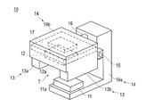
- FIG. 1 is a perspective view showing a schematic configuration of a detection device according to the first embodiment of the present invention
- FIG. 2 is a block diagram showing a schematic configuration of a glucose concentration monitoring system to which the detection device shown in FIG. 1 is applied.
- the detection apparatus 10 according to the present embodiment is a fluorescent hydrogel carrying a fluorescent substance that reacts with glucose in a living body and receives excitation light to emit fluorescence according to the glucose concentration (hereinafter simply referred to as “fluorescent gel”). Is used to detect the glucose concentration in the blood.
- fluorescent gel a fluorescent hydrogel carrying a fluorescent substance that reacts with glucose in a living body and receives excitation light to emit fluorescence according to the glucose concentration
- the detection device 10 includes an LED (Light Emitting Diode) 11 that irradiates a fluorescent gel placed in a living body such as a subcutaneous body, and a fluorescent gel irradiated with the excitation light.
- LED Light Emitting Diode
- PD Photo Diode
- the detection device 10 includes an LED (Light Emitting Diode) 11 that irradiates a fluorescent gel placed in a living body such as a subcutaneous body, and a fluorescent gel irradiated with the excitation light.
- PD Photo Diode 12 that receives the fluorescence emitted from the body, a receiving part 13 that receives the convex part formed on the surface of the living body by placing the fluorescent gel in the living body, and a convex part that is received by the receiving part 13
- Positioning part 14 for positioning LED 11 and PD 12 with respect to the part.
- the LED 11 is a light emitting element that irradiates the fluorescent gel with excitation light.
- the LED 11 irradiates the fluorescent gel with excitation light having a wavelength of 405 nm, for example, and generates fluorescence with a light amount corresponding to the glucose concentration from the fluorescent gel.
- the PD12 is a light receiving element that receives fluorescence emitted from the fluorescent gel.
- the PD 12 receives fluorescence (for example, wavelength 488 nm) emitted from the fluorescent gel irradiated with excitation light, and outputs a current having a magnitude corresponding to the amount of received light.
- the receiving part 13 receives the convex part formed on the surface of the living body as a result of the skin being raised by placing the fluorescent gel in the living body such as under the skin.
- the receiving part 13 is comprised from a pair of guide members 13a and 13b which are each arrange
- the positioning part 14 positions the LED 11 and the PD 12 with respect to the convex part received by the receiving part 13.
- the positioning unit 14 includes a fixed portion 14a and a movable portion 14b that is rotatable with respect to the fixed portion 14a.
- the movable portion 14b is attached to the fixed portion 14a by a hinge 15 so as to be rotatable. Further, the movable portion 14b is biased by a spring 16 as a pressing portion so that the fixed portion 14a and the movable portion 14b can sandwich the test portion.
- the LED 11 and the PD 12 are arranged on the fixed portion 14a and the movable portion 14b so that the light emitting surface 11a of the LED 11 and the light receiving surface 12a of the PD 12 face each other.
- the guide members 13a and 13b constituting the receiving portion 13 protrude downward from both sides of the PD 12 disposed on the lower surface of the movable portion 14b.
- the guide members 13a and 13b and the lower surface of the movable portion 14b constitute a groove T into which a convex portion formed on the surface of the living body is fitted.
- the substrate 17 is built in the movable part 14b.
- An electric circuit 171 and a microcomputer 172 are mounted on the substrate 17.
- the electric circuit 171 functions as a signal amplification unit that drives the LED 11 and amplifies the output signal from the PD 12.
- the microcomputer 172 functions as a data conversion unit that converts the analog signal amplified by the electric circuit 171 into a digital signal, and sends the converted digital signal to the PC 20.
- the PC 20 processes the digital signal transferred from the microcomputer 172 and calculates the glucose concentration.
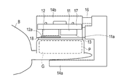
- FIG. 3 (A) is a schematic front view showing a detection device attached to a living body
- FIG. 3 (B) is a schematic side view showing the detection device attached to the living body.
- a plate-like fluorescent gel G is embedded under the skin of the living body B before the detection device 10 is attached to the living body.
- the fluorescent gel G reacts with glucose in the living body B, receives excitation light, and emits fluorescence with a light amount corresponding to the glucose concentration.
- the fluorescent gel G is introduced into the living body B using an indwelling needle (not shown).
- the skin of the living body B is raised, so that a convex portion P is formed on the surface so as to follow the shape of the fluorescent gel G.
- the test portion of the living body B is sandwiched between the fixed portion 14a and the movable portion 14b so that the guide members 13a and 13b receive the convex portion P formed on the surface of the living body B.
- the distance between the guide members 13a and 13b is determined in consideration of the width W of the fluorescent gel G and the thickness of the skin of the living body B. For example, when the width W of the plate-like fluorescent gel G is 1.3 mm, the width of the groove T formed by the guide members 13a and 13b is set to about 2 mm.
- the guide members 13a and 13b When the guide members 13a and 13b are pressed against the surface of the living body B on both sides of the convex portion P by the spring 16, the movement of the convex portion P in the left-right direction (width W direction) is restricted.
- the LED 11 and the PD 12 are positioned with respect to the convex part P in which the movement in the left-right direction is restricted.
- the PD 12 is positioned so as to be in close contact with the upper surface of the convex portion P.
- the convex portion P (that is, the fluorescent gel G in the living body) may move left and right due to pressure.
- the convex portion P since the movement of the convex portion P in the left-right direction is restricted by the guide members 13a and 13b, the convex portion P moves even if the PD 12 is closely attached to the upper surface of the convex portion P. There is nothing.
- excitation light is irradiated to the fluorescent gel G in the living body B from the LED 11 outside the living body B.
- LED11 of this embodiment irradiates excitation light only for a short time (for example, 1 second) with respect to fluorescent gel G after fixed time (for example, 5 minutes).
- the fluorescent gel G irradiated with the excitation light emits fluorescent light with a light amount corresponding to the glucose concentration.
- the fluorescence emitted from the fluorescent gel G is received by the PD 12 outside the living body B.
- the PC 20 calculates the intensity of the fluorescence received by the PD 12 to determine the glucose concentration in the blood of the living body B.
- measurement is performed in a state where the fluorescent gel G, the LED 11, and the PD 12 are positioned with respect to each other, so that the measurement accuracy of glucose concentration over time can be improved. . Moreover, since LED11 and PD12 are arrange
- an optical filter for removing the excitation light is designed without being provided on the light receiving surface 12a of the PD 12. Is possible.
- the detection device 10 of the present embodiment since a plate-like fluorescent gel having excellent adhesion to the light receiving surface 12a of the PD 12 is used, the amount of fluorescence received by the PD 12 is increased.
- the detection device 10 of the present embodiment since the excitation light is irradiated to the fluorescent gel G for a short time after a certain period of time, the deterioration of the fluorescent gel G is suppressed, and the glucose concentration can be monitored over a long period of time. It becomes possible.
- FIG. 4 is a front cross-sectional view showing a schematic configuration of a detection apparatus according to the second embodiment of the present invention.
- the LED 11 and the PD 12 are incorporated in the guide members 13a and 13b.
- the LED 11 and the PD 12 are incorporated in the guide members 13a and 13b so that the light emitting surface 11a of the LED 11 and the light receiving surface 12a of the PD 12 face each other.
- the detection device 10 is downsized. Moreover, since LED11 and PD12 are arrange
- the excitation light irradiated from the LED 11 is absorbed by the fluorescent gel G, it is possible to design without providing an optical filter for removing the excitation light on the light receiving surface 12a of the PD 12.
- FIG. 5 is a side sectional view showing a schematic configuration of a detection apparatus according to the third embodiment of the present invention.
- both the LED 11 and the PD 12 are provided in the movable portion 14 b.
- the LEDs 11 and PD12 are arranged so that the LEDs 11 and PD12 are arranged along the longitudinal direction of the plate-like fluorescent gel G.
- An optical filter 18 for blocking excitation light from the LED 11 is provided on the light receiving surface 12 a of the PD 12.
- the detection device 10 is downsized. Moreover, since LED11 and PD12 are arrange
- the number and arrangement of the LEDs 11 and PD12 are not limited to the example shown in FIG. 5, and the plurality of LEDs 11 and PD12 are arranged alternately along the longitudinal direction of the plate-like fluorescent gel G. May be.
- This embodiment is an embodiment in which an output signal from a detection device is transmitted wirelessly.
- FIG. 6 is a block diagram showing a schematic configuration of a glucose concentration monitoring system to which the detection apparatus according to the fourth embodiment of the present invention is applied.
- the PC 20 is spaced apart from the detection device 10, and a wireless receiver 21 is connected to the PC 20.
- the microcomputer 172 of the detection device 10 functions as a transmission unit that wirelessly transmits a digital signal, and wirelessly transmits the digital signal toward the PC 20.
- the wiring for electrically connecting the detection device 10 and the PC 20 is omitted, the subject can freely act with the detection device 10 attached. That is, the usability of the detection device 10 is improved.
- the detection device according to the present invention has been described through a plurality of embodiments.
- the detection device according to the present invention is not limited to the configuration shown in each embodiment, and various modifications are made based on the description of the claims. can do.
- a plate-like fluorescent gel is used.
- the shape of the fluorescent gel is not limited to a plate shape.
- various shapes such as a spherical shape, a polyhedral shape, a linear shape, or a hollow shape thereof, or a three-dimensional structure constructed by using these shapes can be applied.
- the fluorescent gel preferably has a portion having a length of 500 ⁇ m or more.
- the receiving portion is configured by a pair of guide members in accordance with the plate-like fluorescent gel.
- the configuration of the receiving portion is variously changed according to the shape of the fluorescent gel. For example, when a disc-shaped fluorescent gel is used, a dome-shaped or cylindrical receiving portion is used.
- the glucose concentration is measured using the detection device of the present invention
- the analyte to be measured is not limited to glucose, and various substances such as lactic acid can be measured.
- the fluorescent gel placed in the living body will be described.
- the fluorescent gel may be a fluorescent hydrogel having a structure represented by the following chemical formula 1.
- X 1 and X 2 may be the same or different, and —COO—, —OCO—, —CH 2 NR—, —NR—, —NRCO—, —CONR—, —SO 2 NR— , —NRSO 2 —, —O—, —S—, —SS—, —NRCOO—, —OCONR—, and carbon that may contain at least one substituent selected from the group consisting of —CO— An alkylene group having 1 to 30 carbon atoms, wherein R is a hydrogen atom or a substituted or unsubstituted linear or branched alkyl group having 1 to 10 carbon atoms.
- Z 1 , Z 2 , Z 3 and Z 4 may be the same or different and are —O— or —NR′—, wherein R ′ is a hydrogen atom or a substituted or unsubstituted carbon number. 1 to 10 linear or branched alkyl groups.
- Q, Q ′, Q ′′ and Q ′ ′′ may be the same or different, and may be a hydrogen atom, a hydroxy group, a substituted or unsubstituted C 1-10 linear or branched An alkyl group, an acyl group having 2 to 11 carbon atoms, a substituted or unsubstituted linear or branched alkoxy group having 1 to 10 carbon atoms, a group containing a halogen atom, a carboxyl group, a carboxylate group , A carboxylic acid amide group, a cyano group, a nitro group, an amino group, or an alkylamino group having 1 to 10 carbon atoms, and at least one of Q and Q ′ and Q ′′ and Q ′ ′′ is bonded to each other An aromatic ring or a heterocyclic ring may be formed.
- Y 1 and Y 2 may be the same or different and each is a divalent organic residue or a single bond which may be substituted.
- at least one of Y 1 and Y 2 is represented by the following chemical formula 2 or The structure represented by the following chemical formula 3 may be included.
- n 2 to 5
- j is 1 to 5
- m is 1 to 200
- * represents a bonding point.
- a 1 , A 2 , A 3 and A 4 may be the same or different and are a hydrogen atom or a methyl group.
- U 1, U 2, U 3 and U 4 are the same or different, are hydrogen atoms or are substituted or unsubstituted, straight or branched alkyl group having 1 to 10 carbon atoms, .
- D 1 and D 2 may be the same or different, and are groups represented by the following chemical formula 4.
- R 1 is a hydrogen atom or a linear or branched alkyl group having 1 to 10 carbon atoms, wherein R 1 is L 1 in which D 1 and D 2 are not bonded, A bond may be formed with L 2 , Z 1 or Z 2 , s is an integer of 2 to 5, and t is an integer of 1 to 200.
- L 1 and L 2 may be the same or different, a single bond, -U 5 -, - U 5 -NR 2 -, - U 5 -O -, - U 5 -S -, - U 5 -SS- , -U 5 -NR 2 CO -, - U 5 -CONR 2 -, - U 5 -OCO -, - U 5 -COO-, a group represented by the following chemical formula 5, and a group represented by the following chemical formula 6 A group selected from the group consisting of
- U 5 is a linear or branched alkylene group having or unsubstituted C 1-10 is substituted
- R 2 is 1 carbon atoms or or unsubstituted are hydrogen atoms or substituted 10 to 10 linear or branched alkyl groups.
- the molar ratio between p 1 and q 1 (p 1 : q 1 ) and the molar ratio between p 2 and q 2 (p 2 : q 2 ) is 1:50 to 1: 6,000.
- the molar ratio of p 1 and r 1 (p 1: r 1) and p 2 and the molar ratio of r 2 (p 2: r 2 ) is 1: 5 to 1: 3,000.
- the fluorescent gel may be a fluorescent hydrogel fiber having a structure represented by the following chemical formula 7.
- X 1 and X 2 may be the same or different, and —COO—, —OCO—, —CH 2 NR—, —NR—, —NRCO—, —CONR—, —SO 2 NR— , —NRSO 2 —, —O—, —S—, —SS—, —NRCOO—, —OCONR—, and —CO— containing at least one substituent selected from the group consisting of —CO— Wherein R is a hydrogen atom or a substituted or unsubstituted linear or branched alkyl group having 1 to 10 carbon atoms.
- Z 1 and Z 2 may be the same or different and are —O— or —NR′—, wherein R ′ is a hydrogen atom or a substituted or unsubstituted straight chain having 1 to 10 carbon atoms. Or a branched alkyl group.
- Q, Q ′, Q ′′ and Q ′ ′′ may be the same or different, and may be a hydrogen atom, a hydroxy group, a substituted or unsubstituted C 1-10 linear or branched An alkyl group, an acyl group having 2 to 11 carbon atoms, a substituted or unsubstituted linear or branched alkoxy group having 1 to 10 carbon atoms, a group containing a halogen atom, a carboxyl group, a carboxylate group , A carboxylic acid amide group, a cyano group, a nitro group, an amino group, or an alkylamino group having 1 to 10 carbon atoms, and at least one of Q and Q ′ and Q ′′ and Q ′ ′′ is bonded to each other An aromatic ring or a heterocyclic ring may be formed.
- Y 1 and Y 2 may be the same or different and may be substituted divalent organic residues. At this time, at least one of Y 1 and Y 2 is represented by the following chemical formula 8 or the following chemical formula 9: The structure represented by these may be included.
- n 2 to 5
- j is 1 to 5
- m is 1 to 200
- * represents a bonding point.
- a 1 and A 2 may be the same or different and are a hydrogen atom or a methyl group.
- U 1 , U 2 , U 3 and U 4 may be the same or different and are a hydrogen atom or a substituted or unsubstituted linear or branched alkyl group having 1 to 10 carbon atoms. .
- the molar ratio between p 1 and q 1 (p 1 : q 1 ) and the molar ratio between p 2 and q 2 (p 2 : q 2 ) is 1:50 to 1: 6,000.
- the fluorescent gel may be a fluorescent hydrogel bead having a structure represented by the following chemical formula 10.
- X 1 and X 2 may be the same or different and are —COO—, —OCO—, —CH 2 NR—, —NR—, —NRCO—, —CONR—, —SO 2 NR—. , —NRSO 2 —, —O—, —S—, —SS—, —NRCOO—, —OCONR—, and —CO— containing at least one substituent selected from the group consisting of —CO— Wherein R is a hydrogen atom or a substituted or unsubstituted linear or branched alkyl group having 1 to 10 carbon atoms.
- Z 1 and Z 2 may be the same or different and are —O— or —NR′—, wherein R ′ is a hydrogen atom or a substituted or unsubstituted straight chain having 1 to 10 carbon atoms. Or a branched alkyl group.
- Q, Q ′, Q ′′ and Q ′ ′′ may be the same or different, and may be a hydrogen atom, a hydroxy group, a substituted or unsubstituted C 1-10 linear or branched An alkyl group, an acyl group having 2 to 11 carbon atoms, a substituted or unsubstituted linear or branched alkoxy group having 1 to 10 carbon atoms, a group containing a halogen atom, a carboxyl group, a carboxylate group , A carboxylic acid amide group, a cyano group, a nitro group, an amino group, or an alkylamino group having 1 to 10 carbon atoms, and at least one of Q and Q ′ and Q ′′ and Q ′ ′′ is bonded to each other An aromatic ring or a heterocyclic ring may be formed.
- Y 1 and Y 2 may be the same or different and may be a divalent organic residue which may be substituted.
- a 1 and A 2 may be the same or different and are a hydrogen atom or a methyl group.
- U 1 , U 2 , U 3 and U 4 may be the same or different and are a hydrogen atom or a substituted or unsubstituted linear or branched alkyl group having 1 to 10 carbon atoms. .
- the molar ratio between p 1 and q 1 (p 1 : q 1 ) and the molar ratio between p 2 and q 2 (p 2 : q 2 ) is 1:50 to 1: 6,000.
- Fluorescent material is not limited to the above, and various materials can be used. Further, the fluorescent carrier is not limited to the hydrogel in which the fluorescent substance is covalently bonded, and a fluorescent substance confined in the fluorescent substance can also be used.
- the shape of the fluorescent carrier is not particularly limited, but preferably has a size of 500 ⁇ m. It becomes easy to wear the detection device through the skin. More preferably, the minor axis of the cross section is 0.1 mm to 2.0 mm, and the major axis is 0.2 mm to 10 mm. More preferably, the minor axis is 0.3 mm to 1.4 mm and the major axis is 0.5 mm to 3.0 mm. The length is preferably 5 mm to 30 mm, and more preferably 7 mm to 15 mm.
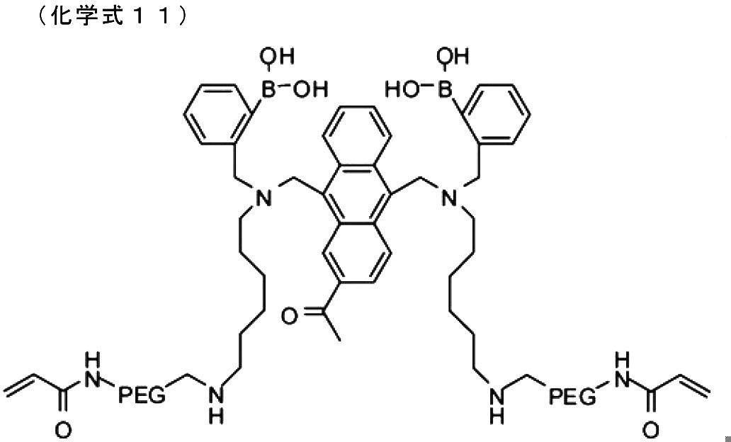
- a fluorescent gel (fluorescent carrier) was prepared and formed into a length of 1.0 mm, a width of 1.4 mm, and a length of 10 mm.
- An example of the prepared fluorescent gel includes a structure represented by the following chemical formula 12.
- the fluorescent gel prepared above was inserted into the needle tube of the indwelling needle and then inserted subcutaneously into the anesthetized rat earlobe. After inserting the indwelling needle, the solid needle was inserted from the rear end of the indwelling needle, and the fluorescent gel was indwelled subcutaneously by retracting only the indwelling needle in the state of being in contact with the fluorescent gel in the needle tube.
- the detection device was attached to the anesthetized rat into which the fluorescent gel was inserted, and the intensity of the fluorescence emitted from the fluorescent gel was continuously measured.
- blood of the rat was collected at a predetermined time interval (5 minute interval), and the blood glucose level was measured. Rats were administered glucose after 40 minutes from the start of measurement, and insulin was administered after 65 minutes to vary the blood glucose level.
- FIG. 7 is a diagram showing the relationship between the measurement result of the fluorescence intensity by the detection device and the blood glucose level.
- the horizontal axis represents time
- the vertical axis represents blood glucose level and fluorescence intensity.
- the fluorescence intensity is a value obtained by converting the output current of the PD 12 into a voltage value.
- the blood glucose level increases with the input of glucose and decreases with the input of insulin.
- the fluorescence intensity also increases with the input of glucose and decreases with the input of insulin, following the change in blood glucose level. Therefore, it was confirmed that the glucose concentration can be accurately measured by the detection device of the present invention.
Landscapes
- Health & Medical Sciences (AREA)
- Life Sciences & Earth Sciences (AREA)
- Physics & Mathematics (AREA)
- Pathology (AREA)
- General Health & Medical Sciences (AREA)
- Medical Informatics (AREA)
- Animal Behavior & Ethology (AREA)
- Optics & Photonics (AREA)
- Veterinary Medicine (AREA)
- Public Health (AREA)
- Surgery (AREA)
- Molecular Biology (AREA)
- Heart & Thoracic Surgery (AREA)
- Biomedical Technology (AREA)
- Biophysics (AREA)
- Engineering & Computer Science (AREA)
- Chemical & Material Sciences (AREA)
- Immunology (AREA)
- Spectroscopy & Molecular Physics (AREA)
- Chemical Kinetics & Catalysis (AREA)
- General Physics & Mathematics (AREA)
- Nuclear Medicine, Radiotherapy & Molecular Imaging (AREA)
- Biochemistry (AREA)
- Analytical Chemistry (AREA)
- Emergency Medicine (AREA)
- Investigating, Analyzing Materials By Fluorescence Or Luminescence (AREA)
- Measurement Of The Respiration, Hearing Ability, Form, And Blood Characteristics Of Living Organisms (AREA)
Description
本発明は、生体内のアナライトの濃度を検知する検知装置および検知方法に関する。
医療の分野において、生体内のアナライトを検出し、その検出結果に基づいて患者や被検者の健康状態や病状を診断して診断結果を各種の処置を行うための指針として活用することが一般的に行われている。特に糖尿病治療においては、患者の血糖値制御のために生体内のグルコース濃度を連続的に長期に亘ってモニタリングすることが推奨されており、従来からこの種のアナライトの検出および診断が採用されている。
グルコースのようなアナライトに関するデータを取得する方法として、たとえば、一定時間おきにサンプルとなる血液を採取して計測を行う方法を採用することがあるが、この方法では、採血をする作業の手間が掛かるうえに、採血による痛みが伴う。
上記のような問題を解決する方法として、たとえば、下記の特許文献1に示されるような生体内に留置可能なアナライト計測用センサを用いる方法が考えられる。このセンサは、生体内のアナライトに反応して、アナライトの濃度に応じた光量の光を発するように構成されている。このため、発せられた光の光量を計測することにより、アナライトの濃度に関するデータを取得することができる。このようなセンサを用いれば、採血する作業を省くことができ、採血による方法で生じ得る問題は解決されると考えられる。
しかしながら、このセンサには、発光を励起するための放射線を発生させる放射線源や、アナライトを検知するための検知器および各種の処理を行うために設けられた電子回路素子が内部に組み込まれており、これらの各構成要素を生体内に導入および留置しなければならない。通常の使用状態においては特に問題は生じないと考えられるが、生体への影響を考慮すると、長期に亘る生体内への留置には不向きであるといえる。また、生体内へ導入するために生体を切開する必要があるため、侵襲性を可能な限り抑えるという課題については十分な対応ができない。
一方、下記の特許文献2および特許文献3には、生体内のアナライトに反応してアナライトの濃度に応じた光量の蛍光を発する蛍光物質を利用した計測方法が提案されている。これらの方法では、生体内に蛍光物質を導入した状態で生体外から蛍光物質に励起光を照射し、励起された蛍光の光量を生体外において観測している。したがって、生体内には蛍光物質以外の計測に要する各種の構成要素を導入する必要がなく、特許文献1に記載されたセンサを利用する場合に比べて、生体への負担を軽減することができる。
上記の特許文献2および特許文献3に記載された方法では、蛍光物質から発せられる蛍光の受光量を確保するため、受光素子を生体の表面に密着させることが好ましい。しかしながら、生体の表面に受光素子を密着させると、圧力により生体内の蛍光物質が移動してしまい、かえって測定精度が低下しまうという問題がある。
そこで、本発明は、計測による生体への負担を軽減しつつ、経時的なアナライトの濃度の計測精度の向上を図ることができる検知装置および検知方法を提供することを目的とする。
本発明に係る検知装置は、生体内のアナライトと反応し励起光を受けて前記アナライトの濃度に応じた蛍光を発する蛍光物質を利用して、前記アナライトの濃度を検知する検知装置であって、前記生体内に留置された前記蛍光物質に前記励起光を照射する発光素子と、前記励起光が照射された前記蛍光物質から発せられる前記蛍光を受光する受光素子と、前記蛍光物質を担持する蛍光担体が前記生体内に留置されることにより前記生体の表面に形成された凸部を受容する受容部と、前記受容部に受容された前記凸部に対して、前記発光素子および前記受光素子を位置決めする位置決め部と、を有する。
本発明に係る検知方法は、生体内のアナライトと反応し励起光を受けて前記アナライトの濃度に応じた蛍光を発する蛍光物質を利用して、前記アナライトの濃度を検知する検知方法であって、前記蛍光物質を担持する蛍光担体が前記生体内に留置されることにより前記生体の表面に形成された凸部を受容部により受容しつつ、前記受容部に受容された前記凸部に対して位置決め部により位置決めされた発光素子により、前記生体内に留置された前記蛍光物質に前記励起光を照射し、前記凸部に対して前記位置決め部により位置決めされた受光素子により、前記励起光が照射された前記蛍光物質から発せられる前記蛍光を受光する。
本発明によれば、受容部により凸部を受容することにより蛍光物質を担持する蛍光担体の移動が規制され、蛍光物質と発光素子と受光素子とを相互に位置決めした状態で計測を行うことが可能となる。このため、経時的なアナライトの濃度の計測精度を向上することができる。また、発光素子および受光素子が生体の外部に配置されるため、計測による生体への負担を軽減することができる。
以下、図面を参照して、本発明の実施形態を説明する。なお、図面の寸法比率は、説明の都合上誇張されており、実際の比率とは異なる場合がある。
(第1実施形態)
図1は、本発明の第1実施形態に係る検知装置の概略構成を示す斜視図であり、図2は、図1に示される検知装置が適用されたグルコース濃度監視システムの概略構成を示すブロック図である。本実施形態に係る検知装置10は、生体内のグルコースと反応し励起光を受けてグルコース濃度に応じた蛍光を発する蛍光物質が担持された蛍光ハイドロゲル(以下、単に「蛍光ゲル」と称する)を利用して、血液中のグルコース濃度を検知する。
図1は、本発明の第1実施形態に係る検知装置の概略構成を示す斜視図であり、図2は、図1に示される検知装置が適用されたグルコース濃度監視システムの概略構成を示すブロック図である。本実施形態に係る検知装置10は、生体内のグルコースと反応し励起光を受けてグルコース濃度に応じた蛍光を発する蛍光物質が担持された蛍光ハイドロゲル(以下、単に「蛍光ゲル」と称する)を利用して、血液中のグルコース濃度を検知する。
図1に示すとおり、本実施形態に係る検知装置10は、皮下などの生体内に留置される蛍光ゲルに励起光を照射するLED(Light Emitting Diode)11と、励起光が照射された蛍光ゲルから発せられる蛍光を受光するPD(Photo Diode)12と、生体内に蛍光ゲルが留置されることにより生体表面に形成された凸部を受容する受容部13と、受容部13に受容された凸部に対してLED11およびPD12を位置決めする位置決め部14と、を有する。
LED11は、蛍光ゲルに励起光を照射する発光素子である。LED11は、たとえば、波長405nmの励起光を蛍光ゲルに照射して、グルコース濃度に応じた光量の蛍光を蛍光ゲルから発生させる。
PD12は、蛍光ゲルから発せられる蛍光を受光する受光素子である。PD12は、励起光が照射された蛍光ゲルから発せられる蛍光(たとえば、波長488nm)を受光し、受光量に応じた大きさの電流を出力する。
受容部13は、蛍光ゲルが皮下などの生体内に留置されることにより皮膚が盛り上がった結果、生体表面に形成された凸部を受容する。受容部13は、生体表面の凸部の両側にそれぞれ配置され当該凸部の移動を規制する一対のガイド部材13a,13bから構成される。
位置決め部14は、受容部13に受容されている凸部に対してLED11およびPD12を位置決めする。位置決め部14は、固定部14aと、固定部14aに対して回動可能な可動部14bとを備える。可動部14bは、ヒンジ15により固定部14aに対して回動可能に取り付けられている。また、可動部14bは、固定部14aと可動部14bとが被検部を挟持可能なように、押し付け部としてのバネ16により付勢されている。固定部14aおよび可動部14bには、LED11の発光面11aとPD12の受光面12aとが相互に対向するように、LED11およびPD12が配置されている。受容部13を構成するガイド部材13a,13bは、可動部14bの下面に配置されるPD12の両側から下方に突出している。ガイド部材13a,13bと可動部14bの下面とは、生体表面に形成された凸部がはめ込まれる溝Tを構成する。
可動部14bには、基板17が内蔵されている。基板17には、電気回路171およびマイコン172が実装されている。電気回路171は、LED11を駆動するとともに、PD12からの出力信号を増幅する信号増幅部として機能する。マイコン172は、電気回路171により増幅されたアナログ信号をデジタル信号に変換するデータ変換部として機能し、変換したデジタル信号をPC20に送出する。PC20は、マイコン172から転送されたデジタル信号を処理して、グルコース濃度を算出する。
以下、図3を参照して、生体に取り付けられた検知装置10について詳細に説明する。
図3(A)は、生体に取り付けられた検知装置を示す概略正面図であり、図3(B)は、生体に取り付けられた検知装置を示す概略側面図である。
本実施形態では、検知装置10を生体に取り付ける前に、生体Bの皮下に、板状の蛍光ゲルGが埋め込まれる。上述したとおり、蛍光ゲルGは、生体B内のグルコースと反応し励起光を受けてグルコース濃度に応じた光量の蛍光を発する。蛍光ゲルGは、留置針(不図示)を用いて、生体B内に導入される。蛍光ゲルGが、生体Bの表面近傍である皮下に埋め込まれることにより、生体Bの皮膚が盛り上がった結果、表面には、蛍光ゲルGの形状に倣うように凸部Pが形成される。
本実施形態に係る検知装置10では、ガイド部材13a,13bが生体Bの表面に形成された凸部Pを受容するように、固定部14aおよび可動部14bにより生体Bの被検部が挟み込まれる。ガイド部材13a,13bの間隔は、蛍光ゲルGの幅Wと生体Bの皮膚の厚さを考慮して決定される。たとえば、板状の蛍光ゲルGの幅Wが1.3mmの場合、ガイド部材13a,13bが構成する溝Tの幅は2mm程度に設定される。
バネ16によりガイド部材13a,13bが凸部Pの両側の生体B表面に押し付けられることにより、凸部Pの左右方向(幅W方向)の移動が規制される。加えて、固定部14aおよび可動部14bが生体Bの被検部を上下から挟み込むことにより、左右方向の移動が規制された凸部Pに対して、LED11およびPD12がそれぞれ位置決めされる。PD12は、凸部Pの上面に密着するように位置決めされる。
PD12を凸部Pの上面に密着させる場合、圧力により凸部P(すなわち、生体内の蛍光ゲルG)が左右に移動するおそれがある。しかしながら、本実施形態の検知装置10では、ガイド部材13a,13bにより凸部Pの左右方向の移動が規制されるため、PD12を凸部Pの上面に密着させても、凸部Pが移動することがない。
そして、蛍光ゲルGとLED11とPD12とが位置決めされた状態で、生体B外のLED11から生体B内の蛍光ゲルGに対して励起光が照射される。本実施形態のLED11は、一定の時間(たとえば、5分)をおいて蛍光ゲルGに対して励起光を短時間(たとえば、1秒)だけ照射する。励起光を照射された蛍光ゲルGは、グルコース濃度に応じた光量の蛍光を発する。蛍光ゲルGから発せられる蛍光は、生体B外のPD12により受光される。そして、PC20において、PD12により受光された蛍光の強度が算出されることにより、生体Bの血液中のグルコース濃度が求められる。
以上のとおり、本実施形態の検知装置10によれば、蛍光ゲルGとLED11とPD12とを相互に位置決めした状態で計測が行われるため、経時的なグルコース濃度の計測精度を向上することができる。また、LED11およびPD12が生体Bの外部に配置されるため、計測による生体Bへの負担を軽減することができる。
また、本実施形態の検知装置10によれば、LED11から照射された励起光が蛍光ゲルGに吸収されるため、励起光を除去するための光学フィルタをPD12の受光面12aに設けることなく設計することが可能である。
また、本実施形態の検知装置10によれば、PD12の受光面12aとの密着性に優れた板状の蛍光ゲルが用いられるため、PD12が受光する蛍光の受光量が増大する。
また、本実施形態の検知装置10によれば、一定の時間をおいて蛍光ゲルGに励起光を短時間だけ照射するため、蛍光ゲルGの劣化が抑制され、長期に亘るグルコース濃度のモニタリングが可能になる。
(第2実施形態)
なお、受容部は、位置決め部を兼ねることができる。図4は、本発明の第2実施形態に係る検知装置の概略構成を示す正面断面図である。
なお、受容部は、位置決め部を兼ねることができる。図4は、本発明の第2実施形態に係る検知装置の概略構成を示す正面断面図である。
図4に示すとおり、本実施形態に係る検知装置10では、ガイド部材13a,13bにLED11およびPD12が組み込まれている。LED11およびPD12は、LED11の発光面11aとPD12の受光面12aとが相互に対向するように、ガイド部材13a,13bの内部に組み込まれている。
このような構成によれば、検知装置10が小型化される。また、LED11とPD12とが生体Bの同側の表面に配置されるため、検知装置10を生体Bの表面に貼り付けて使用することが可能になる。
また、LED11から照射された励起光が蛍光ゲルGに吸収されるため、励起光を除去するための光学フィルタをPD12の受光面12aに設けることなく設計することが可能である。
(第3実施形態)
次に、図5を参照して、本発明の第3実施形態に係る検知装置について説明する。
次に、図5を参照して、本発明の第3実施形態に係る検知装置について説明する。
図5は、本発明の第3実施形態に係る検知装置の概略構成を示す側面断面図である。図5に示すとおり、本実施形態の検知装置10では、LED11およびPD12の両方が、可動部14bに備えられる。LED11およびPD12は、板状の蛍光ゲルGの長手方向に沿ってLED11およびPD12が並ぶように配置される。PD12の受光面12aには、LED11からの励起光を遮断するための光学フィルタ18が設けられている。
このような構成によれば、検知装置10が小型化される。また、LED11とPD12とが生体Bの同側の表面に配置されるため、検知装置10を生体Bの表面に貼り付けて使用することが可能になる。
なお、LED11およびPD12の個数および配列は、図5に示す例に限定されるものではなく、板状の蛍光ゲルGの長手方向に沿って、複数のLED11およびPD12が交互に並ぶように配置されてもよい。
(第4実施形態)
本実施形態は、検知装置からの出力信号が無線送信される実施形態である。
本実施形態は、検知装置からの出力信号が無線送信される実施形態である。
図6は、本発明の第4実施形態に係る検知装置が適用されたグルコース濃度監視システムの概略構成を示すブロック図である。図6に示すとおり、本実施形態に係るグルコース濃度監視システムでは、PC20は、検知装置10と離隔配置されており、PC20には、無線受信機21が接続されている。検知装置10のマイコン172は、デジタル信号を無線送信する送信部として機能し、デジタル信号をPC20に向けて無線送信する。
このような構成によれば、検知装置10とPC20とを電気的に接続する配線が省略されるため、検知装置10を取り付けたまま被検者が自由に行動することが可能となる。つまり、検知装置10の使い勝手が向上する。
以上、本発明に係る検知装置を複数の実施形態を通じて説明したが、本発明に係る検知装置は、各実施形態に示される構成のみに限定されず、特許請求の範囲の記載に基づいて種々改変することができる。
たとえば、上述した第1~第4実施形態では、板状の蛍光ゲルが使用された。しかしながら、蛍光ゲルの形状は、板状に限定されるものではない。蛍光ゲルの形状としては、球状、多面体状、線状、もしくはこれらの中空形状、またはこれらを用いて構築した3次元構造等の種々の形状が適用され得る。なお、長期に亘る十分な蛍光の発光量を確保する見地から、蛍光ゲルは、500μm以上の長さの部位を有することが好ましい。
また、上述した第1~第4実施形態では、板状の蛍光ゲルに合わせて、一対のガイド部材により受容部が構成された。しかしながら、受容部の構成は、蛍光ゲルの形状に応じて種々変更される。たとえば、円板状の蛍光ゲルが用いられる場合には、ドーム形状や円筒形状の受容部が用いられる。
また、上述した第1~第4実施形態では、本発明の検知装置を利用してグルコース濃度を計測する場合を例に挙げて説明した。しかしながら、計測対象のアナライトは、グルコースに限定されるものではなく、乳酸等の種々の物質が計測され得る。
<蛍光ハイドロゲル>
以下、生体内に留置される蛍光ゲルについて説明する。蛍光ゲルは、下記化学式1で表される構造を有する蛍光ハイドロゲルであることができる。
以下、生体内に留置される蛍光ゲルについて説明する。蛍光ゲルは、下記化学式1で表される構造を有する蛍光ハイドロゲルであることができる。

前記化学式1中、X1およびX2は同一または異なっていてもよく、-COO-、-OCO-、-CH2NR-、-NR-、-NRCO-、-CONR-、-SO2NR-、-NRSO2-、-O-、-S-、-SS-、-NRCOO-、-OCONR-、および-CO-からなる群より選択される少なくとも1種の置換基を含んでいてもよい炭素数1~30のアルキレン基であり、この際、Rは、水素原子、または置換されているかもしくは非置換の炭素数1~10の直鎖状もしくは分枝状のアルキル基である。
Z1、Z2、Z3およびZ4は同一または異なっていてもよく、-O-または-NR’-であり、この際R’は、水素原子または置換されているかもしくは非置換の炭素数1~10の直鎖状もしくは分枝状のアルキル基である。
Q、Q’、Q’’、Q’’’は同一または異なっていてもよく、水素原子、ヒドロキシ基、置換されているかもしくは非置換の炭素数1~10の直鎖状もしくは分枝状のアルキル基、炭素数2~11のアシル基、置換されているかもしくは非置換の炭素数1~10の直鎖状もしくは分枝状のアルコキシ基、ハロゲン原子を含む基、カルボキシル基、カルボン酸エステル基、カルボン酸アミド基、シアノ基、ニトロ基、アミノ基、または炭素数1~10のアルキルアミノ基であり、QおよびQ’ならびにQ’’およびQ’’’の少なくとも一方は、互いに結合して芳香環または複素環を形成してもよい。
Y1およびY2は、同一または異なっていてもよく、置換されていてもよい2価の有機残基または単結合であり、この際、Y1およびY2の少なくとも一方が、下記化学式2または下記化学式3で表される構造を含んでいてもよい。

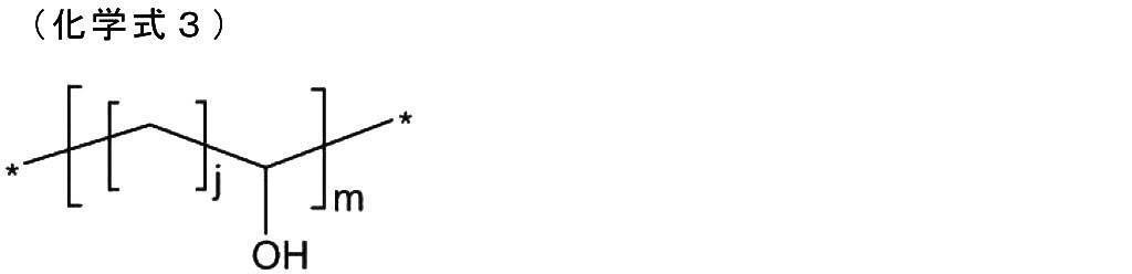
前記化学式2および前記化学式3中、nは2~5であり、jは1~5であり、mは1~200であり、*は結合点を表す。
A1、A2、A3およびA4は同一または異なっていてもよく、水素原子またはメチル基である。
U1、U2、U3およびU4は同一または異なっていてもよく、水素原子、または置換されているかもしくは非置換の炭素数1~10の直鎖状もしくは分枝状のアルキル基である。
D1およびD2は同一または異なっていてもよく、下記化学式4で表される基である。

前記化学式4中、R1は水素原子または炭素数1~10の直鎖状もしくは分枝状のアルキル基であり、この際、R1は、D1およびD2が結合していないL1、L2、Z1またはZ2と結合を形成してもよく、sは2~5の整数であり、tは1~200の整数である。
L1およびL2は同一または異なっていてもよく、単結合、-U5-、-U5-NR2-、-U5-O-、-U5-S-、-U5-SS-、-U5-NR2CO-、-U5-CONR2-、-U5-OCO-、-U5-COO-、下記化学式5で表される基、および下記化学式6で表される基からなる群より選択される基である。
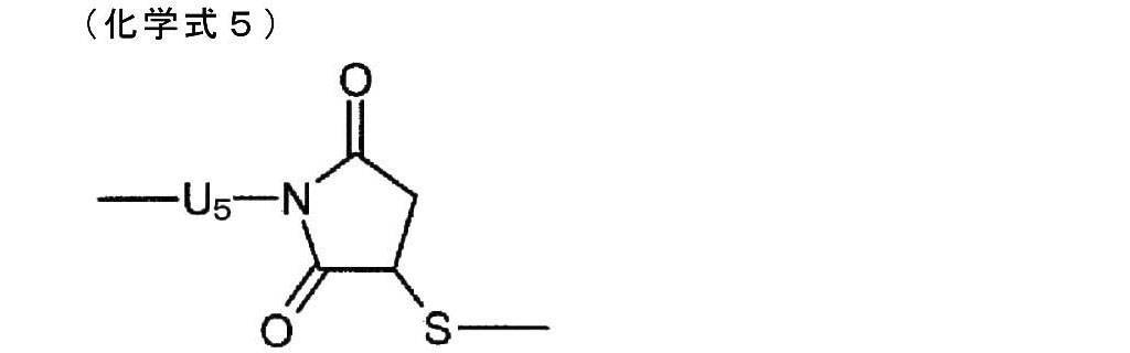
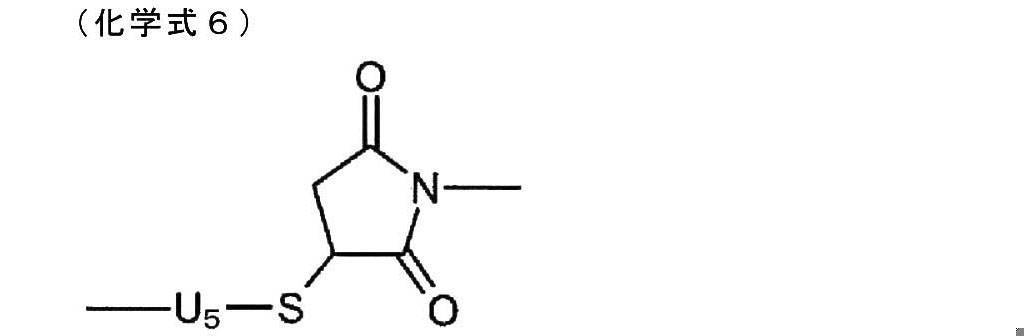
この際、U5は置換されているかまたは非置換の炭素数1~10の直鎖状または分枝状のアルキレン基であり、R2は水素原子または置換されているかもしくは非置換の炭素数1~10の直鎖状もしくは分枝状のアルキル基である。
p1とq1とのモル比(p1:q1)およびp2とq2とのモル比(p2:q2)は、1:50~1:6,000である。
p1とr1とのモル比(p1:r1)およびp2とr2とのモル比(p2:r2)は、1:5~1:3,000である。
あるいは、蛍光ゲルは、下記化学式7で表される構造を有する蛍光ハイドロゲルファイバーであることができる。

前記化学式7中、X1およびX2は同一または異なっていてもよく、-COO-、-OCO-、-CH2NR-、-NR-、-NRCO-、-CONR-、-SO2NR-、-NRSO2-、-O-、-S-、-SS-、-NRCOO-、-OCONR-、および-CO-からなる群より選択される少なくとも1種の置換基を含む炭素数1~30のアルキレン基であり、この際、Rは、水素原子、または置換されているかもしくは非置換の炭素数1~10の直鎖状もしくは分枝状のアルキル基である。
Z1およびZ2は同一または異なっていてもよく、-O-または-NR’-であり、この際、R’は水素原子または置換されているかもしくは非置換の炭素数1~10の直鎖状もしくは分枝状のアルキル基である。
Q、Q’、Q’’、Q’’’は同一または異なっていてもよく、水素原子、ヒドロキシ基、置換されているかもしくは非置換の炭素数1~10の直鎖状もしくは分枝状のアルキル基、炭素数2~11のアシル基、置換されているかもしくは非置換の炭素数1~10の直鎖状もしくは分枝状のアルコキシ基、ハロゲン原子を含む基、カルボキシル基、カルボン酸エステル基、カルボン酸アミド基、シアノ基、ニトロ基、アミノ基、または炭素数1~10のアルキルアミノ基であり、QおよびQ’ならびにQ’’およびQ’’’の少なくとも一方は、互いに結合して芳香環または複素環を形成してもよい。
Y1およびY2は、同一または異なっていてもよく、置換されていてもよい2価の有機残基であり、この際、Y1およびY2の少なくとも一方が、下記化学式8または下記化学式9で表される構造を含んでいてもよい。

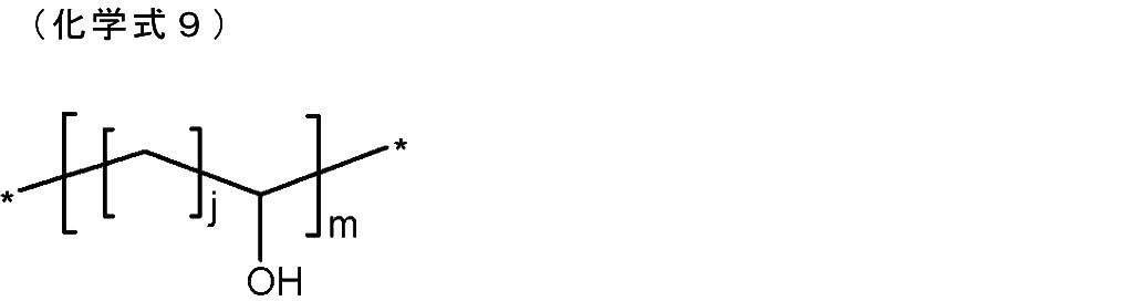
前記化学式8および前記化学式9中、nは2~5であり、jは1~5であり、mは1~200であり、*は結合点を表す。
A1およびA2は同一または異なっていてもよく、水素原子またはメチル基である。
U1、U2、U3およびU4は同一または異なっていてもよく、水素原子、または置換されているかもしくは非置換の炭素数1~10の直鎖状もしくは分枝状のアルキル基である。
p1とq1とのモル比(p1:q1)およびp2とq2とのモル比(p2:q2)は、1:50~1:6,000である。
あるいは、蛍光ゲルは、下記化学式10で表される構造を有する蛍光ハイドロゲルビーズであることができる。

前記化学式10中、X1およびX2は同一または異なっていてもよく、-COO-、-OCO-、-CH2NR-、-NR-、-NRCO-、-CONR-、-SO2NR-、-NRSO2-、-O-、-S-、-SS-、-NRCOO-、-OCONR-、および-CO-からなる群より選択される少なくとも1種の置換基を含む炭素数1~30のアルキレン基であり、この際、Rは、水素原子、または置換されているかもしくは非置換の炭素数1~10の直鎖状もしくは分枝状のアルキル基である。
Z1およびZ2は同一または異なっていてもよく、-O-または-NR’-であり、この際、R’は水素原子または置換されているかもしくは非置換の炭素数1~10の直鎖状もしくは分枝状のアルキル基である。
Q、Q’、Q’’、Q’’’は同一または異なっていてもよく、水素原子、ヒドロキシ基、置換されているかもしくは非置換の炭素数1~10の直鎖状もしくは分枝状のアルキル基、炭素数2~11のアシル基、置換されているかもしくは非置換の炭素数1~10の直鎖状もしくは分枝状のアルコキシ基、ハロゲン原子を含む基、カルボキシル基、カルボン酸エステル基、カルボン酸アミド基、シアノ基、ニトロ基、アミノ基、または炭素数1~10のアルキルアミノ基であり、QおよびQ’ならびにQ’’およびQ’’’の少なくとも一方は、互いに結合して芳香環または複素環を形成してもよい。
Y1およびY2は、同一または異なっていてもよく、置換されていてもよい2価の有機残基である。
A1およびA2は同一または異なっていてもよく、水素原子またはメチル基である。
U1、U2、U3およびU4は同一または異なっていてもよく、水素原子、または置換されているかもしくは非置換の炭素数1~10の直鎖状もしくは分枝状のアルキル基である。
p1とq1とのモル比(p1:q1)およびp2とq2とのモル比(p2:q2)は、1:50~1:6,000である。
蛍光物質は上記に限定されるものではなく種々の物質を用いることができる。また、蛍光担体についても、蛍光物質を共有結合したハイドロゲルに限定されることなく、蛍光物質を閉じ込めたものも用いることができる。
蛍光担体の形状は、特に限定されるものではないが、500μmの寸法を有することが好ましい。皮膚を介して検知装置を装着するのが容易となる。より好ましくは、その断面の短径が0.1mmから2.0mm、長径が0.2mmから10mmである。さらに好ましくは、短径が0.3mmから1.4mm、長径が0.5mmから3.0mmである。また、長さは、5mmから30mmが好ましく、7mmから15mmがより好ましい。
以下、実施例を用いて本発明の実施形態をより詳細に説明する。しかしながら、本発明は、本実施例によって何ら限定されるものではない。
(蛍光担体の作成)
下記化学式11に示す化合物、アクリルアミドおよびメチレンビスアクリルアミドを用いて、蛍光ゲル(蛍光担体)を作成し、縦1.0mm、横1.4mm、長さ10mmに成形した。
下記化学式11に示す化合物、アクリルアミドおよびメチレンビスアクリルアミドを用いて、蛍光ゲル(蛍光担体)を作成し、縦1.0mm、横1.4mm、長さ10mmに成形した。
作成された蛍光ゲルの一例としては、下記化学式12に示す構造が挙げられる。
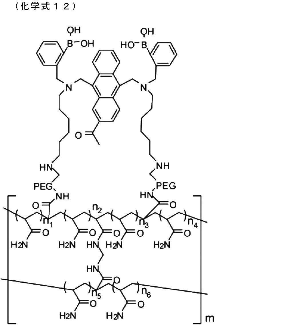
(糖負荷試験)
上記で作成した蛍光ゲルを留置針の針管内に挿入した後、麻酔化のラット耳朶の皮下に挿入した。留置針を挿入後、中実針を前記留置針の後端より挿入し、針管内で蛍光ゲルに当接させた状態で、留置針のみを後退させることにより、蛍光ゲルを皮下に留置した。
上記で作成した蛍光ゲルを留置針の針管内に挿入した後、麻酔化のラット耳朶の皮下に挿入した。留置針を挿入後、中実針を前記留置針の後端より挿入し、針管内で蛍光ゲルに当接させた状態で、留置針のみを後退させることにより、蛍光ゲルを皮下に留置した。
蛍光ゲルが挿入された麻酔下のラットに対して第1実施形態に係る検知装置を装着し、蛍光ゲルから発せられる蛍光の強度を連続的に測定した。同時に、所定の時間間隔(5分間隔)でラットの血液を採取して血糖値を測定した。ラットには、測定開始時点から40分経過後にグルコースを投与し、65分経過後にインスリンを投与して血糖値を変動させた。
図7は、検知装置による蛍光強度の測定結果と血糖値との関係を示す図である。図7の横軸は時間であり、縦軸は血糖値および蛍光強度である。蛍光強度は、PD12の出力電流を電圧値に変換した値である。
図7に示すとおり、血糖値は、グルコースの投入に応じて上昇し、インスリンの投入に応じて低下している。一方、蛍光強度も、グルコースの投入に応じて上昇し、インスリンの投入に応じて低下しており、血糖値の変化に追従していることが分かる。したがって、本発明の検知装置により、グルコース濃度を精度よく測定できることが確認された。
本出願は、2012年7月10日に出願された日本国特許出願第2012-155082号に基づいており、その開示内容は、参照により全体として引用されている。
10 検知装置、
11 LED、
12 PD、
13 受容部、
13a,13b ガイド部材、
14 位置決め部、
14a 固定部、
14b 可動部、
15 ヒンジ、
16 バネ、
17 基板、
171 電気回路、
172 マイコン、
18 光学フィルタ、
B 生体、
G 蛍光ゲル、
P 凸部。
11 LED、
12 PD、
13 受容部、
13a,13b ガイド部材、
14 位置決め部、
14a 固定部、
14b 可動部、
15 ヒンジ、
16 バネ、
17 基板、
171 電気回路、
172 マイコン、
18 光学フィルタ、
B 生体、
G 蛍光ゲル、
P 凸部。
Claims (10)
- 生体内のアナライトと反応し励起光を受けて前記アナライトの濃度に応じた蛍光を発する蛍光物質を利用して、前記アナライトの濃度を検知する検知装置であって、
前記生体内に留置された前記蛍光物質に前記励起光を照射する発光素子と、
前記励起光が照射された前記蛍光物質から発せられる前記蛍光を受光する受光素子と、
前記蛍光物質を担持する蛍光担体が前記生体内に留置されることにより前記生体の表面に形成された凸部を受容する受容部と、
前記受容部に受容された前記凸部に対して、前記発光素子および前記受光素子を位置決めする位置決め部と、を有する検知装置。 - 前記位置決め部は、前記蛍光担体を挟んで前記発光素子および前記受光素子が相互に対向するように、前記発光素子および前記受光素子を位置決めする、請求項1に記載の検知装置。
- 前記受容部は、前記位置決め部を兼ねている、請求項2に記載の検知装置。
- 前記位置決め部は、前記生体の表面上に前記発光素子および前記受光素子が並ぶように、前記発光素子および前記受光素子を位置決めする、請求項1に記載の検知装置。
- 前記蛍光物質を担持する蛍光担体の形状は、球状、多面体状、線状、板状、もしくはこれらの中空形状、またはこれらを用いて構築した3次元構造うちの少なくとも一つを含む、請求項1~4のいずれか1項に記載の検知装置。
- 前記蛍光担体は、500μm以上の長さの部位を有する、請求項5に記載の検知装置。
- 前記発光素子および前記受光素子は、複数備えられている、請求項1~6のいずれか1項に記載の検知装置。
- 前記受容部を生体の表面に対して押し付ける押し付け部をさらに有する、請求項1~7のいずれか1項に記載の検知装置。
- 前記受光素子から出力される信号を無線送信する送信部をさらに有する、請求項1~8のいずれか1項に記載の検知装置。
- 生体内のアナライトと反応し励起光を受けて前記アナライトの濃度に応じた蛍光を発する蛍光物質を利用して、前記アナライトの濃度を検知する検知方法であって、
前記蛍光物質を担持する蛍光担体が前記生体内に留置されることにより前記生体の表面に形成された凸部を受容部により受容しつつ、前記受容部に受容された前記凸部に対して位置決め部により位置決めされた発光素子により、前記生体内に留置された前記蛍光物質に前記励起光を照射し、前記凸部に対して前記位置決め部により位置決めされた受光素子により、前記励起光が照射された前記蛍光物質から発せられる前記蛍光を受光する、検知方法。
Applications Claiming Priority (2)
| Application Number | Priority Date | Filing Date | Title |
|---|---|---|---|
| JP2012155082A JP2015171391A (ja) | 2012-07-10 | 2012-07-10 | 検知装置および検知方法 |
| JP2012-155082 | 2012-07-10 |
Publications (1)
| Publication Number | Publication Date |
|---|---|
| WO2014010564A1 true WO2014010564A1 (ja) | 2014-01-16 |
Family
ID=49916016
Family Applications (1)
| Application Number | Title | Priority Date | Filing Date |
|---|---|---|---|
| PCT/JP2013/068669 Ceased WO2014010564A1 (ja) | 2012-07-10 | 2013-07-08 | 検知装置および検知方法 |
Country Status (2)
| Country | Link |
|---|---|
| JP (1) | JP2015171391A (ja) |
| WO (1) | WO2014010564A1 (ja) |
Citations (3)
| Publication number | Priority date | Publication date | Assignee | Title |
|---|---|---|---|---|
| JPH07299043A (ja) * | 1994-05-10 | 1995-11-14 | Sanyo Electric Co Ltd | 脈拍検出装置 |
| US20030050542A1 (en) * | 2000-03-08 | 2003-03-13 | Bruno Reihl | Device for in-vivo measurement of the concentration of a substance contained in a body fluid |
| JP2007044512A (ja) * | 2005-08-09 | 2007-02-22 | Lifescan Inc | 運動蛍光測定バンド |
-
2012
- 2012-07-10 JP JP2012155082A patent/JP2015171391A/ja active Pending
-
2013
- 2013-07-08 WO PCT/JP2013/068669 patent/WO2014010564A1/ja not_active Ceased
Patent Citations (3)
| Publication number | Priority date | Publication date | Assignee | Title |
|---|---|---|---|---|
| JPH07299043A (ja) * | 1994-05-10 | 1995-11-14 | Sanyo Electric Co Ltd | 脈拍検出装置 |
| US20030050542A1 (en) * | 2000-03-08 | 2003-03-13 | Bruno Reihl | Device for in-vivo measurement of the concentration of a substance contained in a body fluid |
| JP2007044512A (ja) * | 2005-08-09 | 2007-02-22 | Lifescan Inc | 運動蛍光測定バンド |
Also Published As
| Publication number | Publication date |
|---|---|
| JP2015171391A (ja) | 2015-10-01 |
Similar Documents
| Publication | Publication Date | Title |
|---|---|---|
| JP7539355B2 (ja) | 光信号を補正するための方法およびデバイス | |
| JP5788099B2 (ja) | 直交冗長センサシステム及び方法 | |
| ES2541534T3 (es) | Dispositivo de prueba de analitos con cartucho de lancetas y cartucho de tiras reactivas | |
| EP1127265B1 (en) | Method for non-invasive imaging oxygen distribution in multi-dimensions and apparatus therefor | |
| JP2013519483A (ja) | 皮下グルコースセンサ | |
| US12232870B2 (en) | Systems and methods of optical transcutaneous oxygenation monitoring | |
| JP2013505491A (ja) | 医療消耗品のための高密度バーコード | |
| CN112203576B (zh) | 用于非侵入式地监测晚期糖基化终末产物(age)的系统和方法 | |
| JP2017523863A (ja) | 連続検体センサー | |
| ATE412897T1 (de) | Diagnoseverfahren für atherosklerose | |
| AU2021336888A1 (en) | Systems and methods for monitoring an analyte or parameter for a patient | |
| EP2818121B1 (en) | Fluorescence detection device | |
| KR102578444B1 (ko) | 니들 타입 바이오 센서 | |
| WO2014010564A1 (ja) | 検知装置および検知方法 | |
| JP2012223523A (ja) | 光脳機能計測装置 | |
| JP2011078819A (ja) | 非侵襲生体情報計測装置 | |
| JP2011110083A (ja) | 皮膚組織測定用プローブ | |
| WO2014026113A1 (en) | Near-infrared spectroscopy and optical reporter | |
| WO2016096908A1 (en) | Biosensor based on single-molecule fluorescence detection | |
| JP4834350B2 (ja) | 生体情報計測装置及びそのキャリブレーション方法 | |
| JP2011110084A (ja) | 皮膚組織測定用プローブ | |
| JP2011142929A (ja) | 低侵襲血管新生計測装置 | |
| KR20150050264A (ko) | 무채혈 방식의 체내 대사 진단 장치, 및 이를 이용하는 무채혈 방식의 체내 대사 진단 방법 | |
| Katakdond | Synthetic Development in Non-Invasive Glucose Sensing Technique | |
| Anwar | Towards A Wireless Image Sensor for Real-Time Fluorescence Microscopy in Cancer Therapy |
Legal Events
| Date | Code | Title | Description |
|---|---|---|---|
| 121 | Ep: the epo has been informed by wipo that ep was designated in this application |
Ref document number: 13816650 Country of ref document: EP Kind code of ref document: A1 |
|
| NENP | Non-entry into the national phase |
Ref country code: DE |
|
| 122 | Ep: pct application non-entry in european phase |
Ref document number: 13816650 Country of ref document: EP Kind code of ref document: A1 |
|
| NENP | Non-entry into the national phase |
Ref country code: JP |