WO2014010525A1 - 予測ベクトル生成装置、および画像復号装置 - Google Patents
予測ベクトル生成装置、および画像復号装置 Download PDFInfo
- Publication number
- WO2014010525A1 WO2014010525A1 PCT/JP2013/068483 JP2013068483W WO2014010525A1 WO 2014010525 A1 WO2014010525 A1 WO 2014010525A1 JP 2013068483 W JP2013068483 W JP 2013068483W WO 2014010525 A1 WO2014010525 A1 WO 2014010525A1
- Authority
- WO
- WIPO (PCT)
- Prior art keywords
- vector
- unit
- prediction
- candidate
- block
- Prior art date
- Legal status (The legal status is an assumption and is not a legal conclusion. Google has not performed a legal analysis and makes no representation as to the accuracy of the status listed.)
- Ceased
Links
Images













Classifications
-
- H—ELECTRICITY
- H04—ELECTRIC COMMUNICATION TECHNIQUE
- H04N—PICTORIAL COMMUNICATION, e.g. TELEVISION
- H04N19/00—Methods or arrangements for coding, decoding, compressing or decompressing digital video signals
- H04N19/50—Methods or arrangements for coding, decoding, compressing or decompressing digital video signals using predictive coding
- H04N19/503—Methods or arrangements for coding, decoding, compressing or decompressing digital video signals using predictive coding involving temporal prediction
- H04N19/51—Motion estimation or motion compensation
- H04N19/513—Processing of motion vectors
- H04N19/517—Processing of motion vectors by encoding
- H04N19/52—Processing of motion vectors by encoding by predictive encoding
-
- H—ELECTRICITY
- H04—ELECTRIC COMMUNICATION TECHNIQUE
- H04N—PICTORIAL COMMUNICATION, e.g. TELEVISION
- H04N13/00—Stereoscopic video systems; Multi-view video systems; Details thereof
- H04N13/10—Processing, recording or transmission of stereoscopic or multi-view image signals
- H04N13/106—Processing image signals
- H04N13/161—Encoding, multiplexing or demultiplexing different image signal components
-
- H—ELECTRICITY
- H04—ELECTRIC COMMUNICATION TECHNIQUE
- H04N—PICTORIAL COMMUNICATION, e.g. TELEVISION
- H04N19/00—Methods or arrangements for coding, decoding, compressing or decompressing digital video signals
- H04N19/50—Methods or arrangements for coding, decoding, compressing or decompressing digital video signals using predictive coding
- H04N19/597—Methods or arrangements for coding, decoding, compressing or decompressing digital video signals using predictive coding specially adapted for multi-view video sequence encoding
Definitions
- the present invention relates to a prediction vector generation device, an image encoding device, and an image decoding device.
- motion prediction is performed by dividing a frame into blocks and acquiring an image close to the block from another frame as a predicted image.
- a vector indicating an image close to the block is referred to as a motion vector
- the motion vector of the block is predicted from the motion vectors of the blocks around the block (for example, Non-Patent Documents 1, 2, 4).
- a vector obtained by motion vector prediction is referred to as a prediction vector.
- ISO International Organization For Standardization
- ISO International Organization For Standardization
- motion information such as the above-described motion vector is converted from a reference layer (for example, a non-base viewpoint image) different from the encoding target layer (for example, a base viewpoint image).
- a reference layer for example, a non-base viewpoint image
- the encoding target layer for example, a base viewpoint image
- the motion information is used as an additional prediction candidate added separately from the prediction candidate used for encoding the base layer image (base viewpoint image).
- the additional prediction candidate since it is necessary to derive a displacement vector (disparity vector) indicating the positional relationship between the encoding target layer and another reference layer, there is a problem that the processing amount increases.
- the present invention has been made in view of such circumstances, and an object thereof is to provide a prediction vector generation device, an image encoding device, and an image decoding device that can reduce the processing amount of additional prediction candidate derivation. There is.
- the present invention has been made to solve the above-described problems, and one aspect of the present invention is a prediction vector generation device that generates a motion vector of a target block or a prediction vector of a disparity vector in a non-reference viewpoint image.
- An additional candidate vector deriving unit that derives a disparity vector of the target block and is referred to by the derived disparity vector, a motion vector related to a block in another viewpoint image, or the derived disparity vector as a candidate vector
- a basic candidate vector deriving unit for deriving one or more candidate vector groups from vectors related to adjacent blocks temporally and spatially adjacent to the target block, a candidate vector derived by the additional candidate vector deriving unit,
- One of candidate vector groups derived by the basic candidate vector deriving unit A prediction vector selection unit that selects based on the index and sets the prediction vector of the target block, and the additional candidate vector deriving unit indicates the candidate vector derived by the additional candidate vector deriving unit. Only in this case, a candidate vector is
- another aspect of the present invention is the prediction vector generation device according to (1), wherein the additional candidate vector deriving unit derives an additional candidate vector when the index value is 0. It is characterized in that it is determined that the candidate vector derived by the section is shown.
- another aspect of the present invention is the prediction vector generation device according to (2), in which the additional candidate vector derivation unit is a block in another viewpoint image referred to by the derived disparity vector. Is a motion vector, a predetermined fixed vector is set as an additional candidate vector.
- the prediction vector generation device according to (3), wherein the additional candidate vector derivation unit derives a zero vector as a predetermined fixed vector. .
- the other aspect of this invention is an image decoding apparatus provided with the prediction vector production
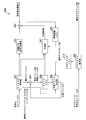
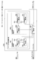
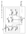
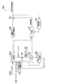
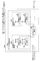
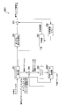
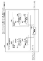
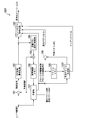
- FIG. 1 is a schematic block diagram illustrating a configuration of an image transmission system 10 according to a first embodiment of the present invention. It is a schematic block diagram which shows the structure of the image decoding apparatus 300 which concerns on the embodiment. It is a schematic block diagram which shows the structure of the prediction vector production
- generation part 306 which concerns on the embodiment. It is a schematic block diagram which shows the structure of another image decoding apparatus 300x which concerns on the embodiment. It is a schematic block diagram which shows the structure of the image coding apparatus 100 which concerns on the same embodiment. It is a schematic block diagram which shows the structure of the prediction vector production
- FIG. 21 (a) is a diagram illustrating a first encoded data configuration indicating the encoding method of the index idx according to the first to fourth embodiments.
- FIG. 21B is a diagram showing the relationship between the index idx and the candidate vector in the first encoded data configuration.
- FIG. 22 (a) is a diagram illustrating a first encoded data configuration indicating the encoding method of the index idx according to the first to fourth embodiments.
- FIG. 21 (a) is a diagram illustrating a first encoded data configuration indicating the encoding method of the index idx according to the first to fourth embodiments.
- FIG. 22B is a diagram illustrating the relationship between the index idx and the candidate vector in the first encoded data configuration.
- FIG. 23 (a) is a diagram illustrating a first encoded data configuration indicating an index idx encoding method according to the first to fourth embodiments.
- FIG. 23B is a diagram showing the relationship between the index idx and the candidate vector in the first encoded data configuration. It is a schematic block diagram which shows the structure of the image decoding apparatus 300d by 5th Embodiment of this invention. It is a schematic block diagram which shows the structure of the prediction vector production
- FIG. 1 is a schematic block diagram showing the configuration of an image transmission system 10 according to the first embodiment of the present invention.
- the image transmission system 10 is a system that encodes and transmits a plurality of viewpoint images and a depth map, and enables display of a free viewpoint image using these at the transmission destination.
- the image transmission system 10 includes an image encoding device 100, a network 200, an image decoding device 300, and a free viewpoint image display device 400.
- the image encoding device 100 encodes each of a plurality of viewpoint images (also referred to as texture images) T, and generates an encoded stream Te of each viewpoint image T. Furthermore, the image encoding device 100 encodes the depth map D corresponding to each of the encoded viewpoint images T, and generates a depth map encoded stream De for each of the depth maps.
- the network 200 is a network such as an IP (Internet Protocol) network or a cable television network that transmits the encoded stream Te and the depth map encoded stream De to the image decoding apparatus 300.
- the encoded stream Te and the depth map encoded stream De may be transmitted via a network as in the present embodiment, but may be transmitted via a broadcast wave such as terrestrial digital broadcast or satellite broadcast, or a DVD. It may be transmitted by a recording medium such as (Digital Versatile Disc) or Blu-ray (Blu-ray (registered trademark)).
- the image decoding apparatus 300 decodes the encoded stream Te and the depth map encoded stream De transmitted by the network 200, and generates a decoded viewpoint image Td and a decoded depth map Dd.
- the free viewpoint image display device 400 generates an image from an arbitrary viewpoint using the decoded viewpoint image Td and the decoded depth map Dd generated by the image decoding device 300.
- the free viewpoint image display device 400 includes a display device such as a liquid crystal display or an organic EL (electroluminescence) display, and displays a generated image from an arbitrary viewpoint using the display device.
- the image from this arbitrary viewpoint may be a two-dimensional image or a stereoscopic image.
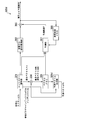
- FIG. 2 is a schematic block diagram showing the configuration of the image decoding apparatus 300.
- the image decoding apparatus 300 includes an entropy decoding unit 301, an inverse quantization / inverse DCT conversion unit 302, an addition unit 303, an addition unit 304, a vector memory 305, a prediction vector generation unit 306 (a prediction vector generation device). ), A prediction unit 307, a reference image memory 308, a depth map decoding unit 309, and a depth map memory 310.
- the prediction vector generation unit 306 is configured to generate a prediction vector without using a depth map
- a configuration without the depth map generation unit 311 is also possible.
- the entropy decoding unit 301 performs entropy decoding processing on the encoded stream Te.
- the entropy decoding unit 301 separates the reference picture index refIdx, index idx, difference vector ⁇ v, quantization coefficient, and prediction mode from the result of this decoding process.
- the reference picture index refIdx is an index for designating a reference picture. When the prediction image can be generated from two prediction pictures, the prediction picture is designated using the reference list L0 and the reference list L1.
- the reference picture indexes of the reference list L0 and the reference list L1 are refIdxL0 and refIdxL1, and the indexes idx of the reference list L0 and the reference list L1 are mvp_l0_idx and mvp_l1_idx.
- refIdxLX refIdx
- mvp_lX_idx mvp_lX_idx
- the inverse quantization / inverse DCT transform unit 302 performs the same process as the inverse quantization / inverse DCT transform unit 104 in FIG. 2 on the quantized coefficients separated by the entropy decoding unit 301, and further, The inverse quantized result is subjected to inverse DCT transform to generate a decoded residual signal.
- the addition unit 303 adds the decoded residual signal generated by the inverse quantization / inverse DCT conversion unit 302 and the predicted image P generated by the prediction unit 307, thereby generating a decoded viewpoint image Td.
- the addition unit 304 adds the difference vector ⁇ v separated by the entropy decoding unit 301 and the prediction vector Pv generated by the prediction vector generation unit 306 to generate a motion vector Mv or a disparity vector Dv.
- the adding unit 304 stores the generated motion vector Mv and the disparity vector Dv in the vector memory 305.
- the vector memory 305 stores prediction parameters of processed (encoded / decoded) blocks, for example, a motion vector Mv and a disparity vector Dv.
- the vector memory 305 stores a prediction mode PredMode, prediction flags predFlagL0, predFlagL1, reference picture indexes refIdxL0, refIdxL1, and vectors mvL0, mvL1.
- predFlagL0 and predFlagL1 indicate whether or not reference pictures belonging to each reference list L0 and reference list L1 are used for predictive image generation.
- the vectors mvL0 and mvL1 are the motion vector Mv or the disparity vector Dv.
- the vector mvLX is a disparity vector, and if different, the vector mvLX is a motion vector (where X is 0 or 1).
- the prediction vector generation unit 306 generates the prediction vector Pv with reference to the reference picture index refIdx and the index idx separated by the entropy decoding unit 301.
- the vector stored in the vector memory 305 and the decoded depth map Dd stored in the depth map memory 310 are referred to. Details of the prediction vector generation unit 306 will be described later.
- the prediction unit 307 generates a predicted image P for each block obtained by dividing the viewpoint image T.
- the prediction unit 307 generates a prediction image P of each block using a prediction method indicated by the prediction mode separated by the entropy decoding unit 301.
- the reference image for generating the predicted image P is acquired from the reference image memory 308.
- intra prediction is performed to generate the prediction image P.
- the prediction unit 307 When the prediction mode indicates motion prediction or disparity prediction, the prediction unit 307 performs motion prediction using the reference picture index refIdx, motion vector Mv, or disparity vector Dv of the block stored in the vector memory 305. To generate a predicted image P.
- the reference image memory 308 stores the decoded viewpoint image Td generated by the addition unit 303 as a reference image.
- the depth map decoding unit 309 performs a decoding process on the depth map encoded stream De, and generates a decoded depth map Dd.
- the depth map memory 310 stores the decoded depth map Dd generated by the depth map decoding unit 309.
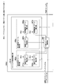
- FIG. 3 is a schematic block diagram showing the configuration of the prediction vector generation unit 306.
- the prediction vector generation unit 306 includes a vector prediction candidate derivation unit 361 and a prediction vector selection unit 368.
- the vector prediction candidate derivation unit 361 includes an additional candidate vector derivation unit 362 and a basic candidate vector derivation unit 365.
- the basic candidate vector derivation unit 365 operates regardless of whether or not the target image is a reference viewpoint image, whether or not it is a non-reference viewpoint image, and one or more predictions used in the non-reference viewpoint image and the reference viewpoint image Derive a vector.
- a space candidate vector deriving unit 366, a time candidate vector deriving unit 367, and a fixed vector deriving unit (not shown) are configured.
- the additional candidate vector derivation unit 362 derives a prediction vector (additional prediction candidate) for the non-reference viewpoint image. It includes a disparity vector deriving unit 363, a motion vector deriving unit 364, and a fixed vector deriving unit (not shown).
- the additional candidate vector deriving unit 362, the internal parallax vector deriving unit 363, and the motion vector deriving unit 364 operate only when the target image is a non-reference viewpoint image.
- One configuration of the disparity vector deriving unit 363 derives a disparity vector using a depth map.
- the disparity vector deriving unit 363 generates a disparity vector Dv from the depth value of the block having the same coordinates as the target block in the decoding depth map Dd corresponding to the encoding target frame.
- the disparity vector deriving unit 363 outputs the generated disparity vector Dv to the motion vector deriving unit 364 when the vector of the target block is the motion vector Mv. If the target block vector is the disparity vector Dv, the disparity vector deriving unit 363 outputs the generated disparity vector as an additional candidate vector to the prediction vector determining unit 368.
- the depth value the depth value of the center coordinate of the block in the decoded depth map Dd may be used, or the average value, mode value, maximum value, and minimum value of the depth values of each pixel in the block. May be used.
- FIG. 5 is a conceptual diagram illustrating the operation of the configuration using the depth map of the disparity vector deriving unit 363.
- an image NBV is a frame with a non-reference viewpoint image.
- the image BV is a frame having a reference viewpoint image, and is a frame having the same display order (POC) as the image NBV.
- the image NBVD is a depth map Dd corresponding to the image NBV.
- Symbol Bo is a target block of the image NBV
- symbol Bd is a block having the same coordinates as the target block in the reference viewpoint image BV.
- the disparity vector deriving unit 363 reads the depth value of the block Bd of the decoded depth map Dd corresponding to the target block Bo from the depth map memory 122.
- an average value of the depth values of the block Bd of the decoded depth map Dd having the same coordinates as the target block Bo is read as the depth value.
- the disparity vector derivation unit 363 converts the average value of the read depth values into a disparity vector Dv.
- the disparity vector deriving unit 363 sets the disparity vector Dv as an additional candidate vector.
- the derivation target vector is a disparity vector when the reference picture index (refIdx) and the POC of the reference picture specified by the reference list (RefPicListX) are equal to the POC of the target image NBV, and a motion vector when they are different. Become.
- the disparity vector deriving unit 363 derives a disparity vector without using a depth map.
- the disparity vector deriving unit 363 first acquires a disparity vector Dv of a block adjacent to the target block.
- the disparity vector deriving unit 363 includes an adjacent disparity vector deriving unit, a temporal disparity vector deriving unit, and a fixed disparity vector deriving unit (not shown).
- the disparity vector deriving unit 363 refers to the availability of the disparity vector of each block in the order of the blocks NBa0 and NBa1 adjacent to the left side of the target block in the adjacent disparity vector deriving unit, and when there is an available disparity vector Selects the disparity vector of the first referenced block. If there is no available disparity vector in any of the blocks adjacent to the left, the adjacent disparity vector deriving unit further disparity vectors of the respective blocks in the order of the blocks NBb0, NBb1, and NBb2 adjacent to the upper side of the target block. In the case where there is a disparity vector that can be used, the disparity vector of the block referred to first is selected.
- the temporal disparity vector deriving unit included in the disparity vector deriving unit 363 temporally disparity of the block corresponding to the target block of the block included in the reference picture in another display order Get a vector.
- the disparity vector deriving unit 363 sets the first candidate vector as a zero vector in the fixed disparity vector acquiring unit.
- the disparity vector deriving unit 363 refers to the motion vector and disparity vector of a certain block X (X is one of the above blocks) as follows. With reference to the prediction mode predMode of the block X or the two prediction flags predFlagL0 and predFlagL1 of the block X, it is checked whether or not the block X is inter-predicted. If the prediction mode predMode is MODE_INTRA, intra prediction is used. Otherwise, inter prediction is used. The prediction flags predFlagL0 and predFlagL1 indicate whether or not reference pictures belonging to the reference list L0 and the reference list L1 are used for prediction image generation. If the prediction flags predFlagL0 and predFlagL1 are both 1, bi-prediction of inter prediction, if only one of them is 1, inter-prediction single prediction, and if both are 0, intra-prediction.
- RefPicListX is an array for referring to the reference picture from the reference picture index redIdxLX
- PicOrderCnt (x) is a function for obtaining the display order of the reference picture specified by the argument x.
- the reference picture index refIdxL0 for the L0 list of the target block the reference picture index refIdxL0 for the L0 list of the block X and the vector for the reference list L0 are referred to, but the reference for the reference list L1 of the block X You may refer to the picture index ref_L1idx and the vector for the reference list L0. The same applies to the reference picture index refIdxL1 for the reference list L1 of the target block.
- the vector mvLX of the block X held in the vector memory is a motion vector, the motion vector is available, and the motion vector is derived.
- the vector mvLX of the block X held in the vector memory is a disparity vector, the disparity vector is available, and the disparity vector is derived.
- the motion vector deriving unit 364 refers to the disparity vector Dv generated by the disparity vector deriving unit 363, selects a block (also referred to as a corresponding block) in another viewpoint image indicated by the disparity vector Dv, and the motion of the block The vector Mv is read from the vector memory 305.
- the motion vector deriving unit 364 notifies the prediction vector determining unit 368 of the read motion vector Mv as an additional candidate vector.
- the motion vector Mv acquired by the motion vector deriving unit 364 is indicated by the disparity vector Dv generated by the disparity vector deriving unit 363 when the center point of the target block is the starting point.
- a block containing a point Note that the coordinates of the point indicated by the parallax vector Dv are coordinates obtained by adding the parallax vector Dv to the coordinates of the starting point.
- the corresponding block belongs to a frame of a viewpoint image of another viewpoint that is referenced by the disparity vector Dv in the same display order as the frame to which the target block belongs.
- a motion vector Mvc included in a block Bp (also referred to as a corresponding block) on an image BV corresponding to the target block Bo is read from the vector memory 109 and set as an additional candidate vector.
- the corresponding block Bp is obtained by a block including a point indicated by the disparity vector Dv when the starting point is the point Cb in the reference viewpoint image having the same coordinates as the center Cn of the target block Bo.
- the block Bp does not have a motion vector.
- the additional candidate vector deriving unit 362 determines a predetermined fixed vector as an additional candidate vector in the fixed vector deriving unit (not shown). To do. Through the above process, the additional candidate vector deriving unit 362 derives a candidate vector. A zero vector is appropriate as the predetermined fixed vector.
- mvpListLX [depthCandIdx] [0] 0
- mvpListLX [depthCandIdx] [1] 0
- mvpListLX [i] [j] indicates a motion vector of a prediction vector candidate of the list LX (X is 0 or 1) in the list index i and the direction j.
- the list index i indicates the order of prediction vector candidates.
- j 0 indicates an X direction motion vector
- the spatial candidate vector derivation unit 366 included in the basic candidate vector derivation unit 362 reads a vector (motion vector Mv or disparity vector Dv) of an adjacent block adjacent to the target block from the vector memory 305 and determines a prediction vector as a spatial candidate vector. Notification to the unit 368.
- the spatial candidate vector derivation unit 366 reads a vector (motion vector Mv or disparity vector Dv) from one or a plurality of adjacent blocks, and notifies the prediction vector determination unit 368 as one or more spatial candidate vectors. If the vector of the target block is the motion vector Mv and the adjacent block has the parallax vector Dv, the spatial candidate vector deriving unit 366 notifies the prediction vector determining unit 368 that there is no candidate vector.
- the target block has the disparity vector Dv and the adjacent block has the motion vector Mv.
- the number of candidate vectors is two at the maximum, but other numbers may be used.
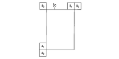
- FIG. 4 is a conceptual diagram illustrating the operation of the space candidate vector deriving unit 366.
- the symbol Bo is a target block
- the rectangles to which the symbols A 0 , A 1 , B 0 , B 1 , B 2 are attached are adjacent blocks to the target block Bo.
- the space candidate vector derivation unit 366 a motion vector or disparity vectors of the neighboring blocks a 0 to the first space candidate vectors.
- the adjacent block A 0 does not have a motion vector or a disparity vector, or if the vector of the adjacent block A 0 and the vector of the target block are of different types, then the adjacent block A 1 The same processing is performed for. If even the adjacent block A 1 does not have the appropriate motion vector or disparity vector, it notifies the predicted vector determining unit 368 that the first space candidate vectors is not.
- the space candidate vector derivation unit 366 performs the same process on the adjacent block B 0 to set the third candidate vector.
- the adjacent block B 0 does not have an applicable vector
- the same processing is performed in the order of the adjacent blocks B 1 and B 2 .
- the prediction vector determination unit 368 is notified that there is no second spatial candidate vector.
- the first space candidate and the second space candidate vector are derived as the first candidate vector and the second candidate vector when the target image is a reference viewpoint image, and the second space candidate when the target image is a non-reference viewpoint image. Derived as a candidate vector and a third candidate vector. Note that, as described in Non-Patent Document 2, a vector obtained by performing scaling processing on the motion vector or disparity vector of each adjacent block may be used as a candidate vector.
- the temporal candidate vector deriving unit 367 included in the basic candidate vector deriving unit 362 obtains the motion vector Mv or the disparity vector Dv of the block having the same coordinate as that of the target block from the reference image having the same viewpoint as that of the encoding target frame.
- a readout time candidate vector is derived from.
- the first space candidate vector or the second space candidate vector does not exist.
- the time candidate vector is derived only when the first space candidate vector matches the second space candidate vector.
- the spatial candidate vector derivation unit 366 notifies the read motion vector Mv or the disparity vector Dv to the prediction vector determination unit 368 as a temporal candidate vector.
- the motion vector Mv or the disparity vector Dv of not only the block having the same coordinates but also a block adjacent to the block may be used as a candidate vector. Further, when the derivation target is the motion vector Mv and the vector of the corresponding block is the disparity vector Dv, the prediction vector determination unit 368 is notified that there is no time candidate vector. The same applies to the case where the derivation target vector is the disparity vector Dv and the vector of the corresponding block is the motion vector Mv.
- the prediction vector selection unit 368 selects a prediction candidate vector from each candidate vector with reference to the index idx.
- a prediction candidate vector is selected from candidate vectors derived from the basic candidate vector derivation unit 365.
- an additional candidate vector derivation unit 362 and A prediction vector is selected from candidate vectors input from the basic candidate vector deriving unit 365.
- the selected prediction vector is output to the adding unit 304 as the prediction vector Pv.
- the prediction vector selection unit 368 selects an additional candidate vector when the value of the index idx is 0, and a basic candidate vector when the value is 1. However, when it is notified that there is no candidate vector, the value of the index idx indicating the candidate vector after the candidate vector notified of the absence is decreased by one. For example, when it is notified that there is no first candidate vector, the second candidate vector is selected with the value 1 of the index idx.
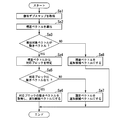
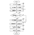
- FIG. 6 is a flowchart for explaining the operation of the additional candidate vector deriving unit 362.
- the process shown in the flowchart of FIG. 6 is the process of the additional candidate vector deriving unit 362 for one target block that generates a predicted image by motion prediction.
- the disparity vector deriving unit 363 acquires, from the depth map memory 310, a depth value of a block having the same coordinates as the target block in the decoded depth map Dd corresponding to the encoding target frame. (Sa1). In the case of a configuration that does not use a depth map, a depth value is not derived.
- the disparity vector deriving unit 363 derives a disparity vector (Sa2).
- the depth value derived in the previous step is converted into a disparity vector.
- the disparity vector deriving unit 363 determines whether the vector to be derived is a motion vector (motion prediction) or a disparity vector (disparity prediction) (Sa3). If it is generated by motion prediction (Sa3-Yes), the disparity vector Dv is output to the motion vector deriving unit 364, and the process proceeds to step Sa4. If not generated by motion prediction (Sa3-No), the disparity vector Dv is set as an additional candidate vector (Sa8), and the process is terminated.
- the motion vector deriving unit 364 identifies a corresponding block in another viewpoint image from the parallax vector Dv (Sa4).
- the motion vector deriving unit 364 determines whether a motion vector exists in the identified corresponding block (Sa5). When it is determined that it exists (Sa5-Yes), the motion vector deriving unit 364 acquires the motion vector from the vector memory 109, sets it as an additional candidate vector (Sa6), and ends the processing. On the other hand, if it is determined in step Sa5 (Sa5-No) that the fixed vector (zero vector here) is an additional candidate vector (Sa7), the process is terminated.
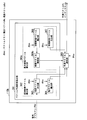
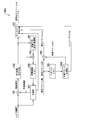
- FIG. 7 is a flowchart for explaining the operation of the prediction vector generation unit 306.
- the prediction vector generation unit 306 acquires the reference picture indexes (reference picture indexes refIdxL0 and refIdxL1) and the index idx of the target block separated by the entropy decoding unit 301 (Sb1).
- the target image is a reference viewpoint image or a non-reference viewpoint image (Sb2). If the target image is a non-reference viewpoint image, the additional candidate vector deriving unit 362 performs the process shown in FIG. 6 to determine an additional candidate vector (Sb3).
- a basic candidate vector is derived by the following process (Sb4).
- the basic candidate vector deriving unit 365 derives the first candidate vector to the second candidate vector.
- the space candidate vector derivation unit 366 sets the motion vector Mv of the adjacent block as the first candidate vector and the second candidate vector.
- the temporal candidate vector derivation unit 367 acquires the motion vector Mv of the temporally adjacent block and sets it as the first candidate vector.
- the motion vector Mv of the temporally adjacent block is acquired and set as the second candidate vector.
- the basic candidate vector deriving unit 365 derives the second candidate vector and the third candidate vector. That is, the space candidate vector derivation unit 366 acquires the motion vector Mv or the disparity vector Dv of the adjacent block and sets it as the second candidate vector and the third candidate vector.
- the temporal candidate vector derivation unit 367 acquires the motion vector Mv of the temporally adjacent block and sets it as the second candidate vector.
- the motion vector Mv of the temporally adjacent block is acquired and set as the third candidate vector.
- the prediction vector determination unit 368 selects a prediction vector according to the index idx (Sb5).
- a prediction vector is selected from an additional candidate vector (first candidate vector) and a basic candidate vector (second candidate vector, third candidate vector).
- a prediction vector is selected from basic candidate vectors (first candidate vector and second candidate vector).
- the prediction vector selection unit 368 outputs the vector selected in step Sb5 to the addition unit 304 as the prediction vector Pv (Sb6).
- the additional candidate vector derivation unit 362 always generates an additional candidate vector. That is, in the method of deriving from the depth map and the method of deriving from the adjacent block in the additional candidate vector deriving unit 362, when a disparity vector and a motion vector cannot be obtained as the additional candidate vector, a predetermined fixed vector as the additional candidate vector Is used.
- the prediction vector is the additional candidate vector generated by the additional candidate vector deriving unit 362, and when the index idx is 1 or more
- the prediction vector is a candidate vector generated by the basic candidate vector deriving unit 365.
- whether the prediction vector is an additional candidate vector or a basic candidate vector can be identified by the index idx. It is possible to prevent the candidate vector derivation process from being performed, and conversely, when the index idx indicates an additional candidate vector, the basic candidate vector derivation process is prevented from being performed. More specifically, the disparity vector deriving unit 363 and the spatial candidate vector deriving unit 366 can be prevented from operating simultaneously, and the motion vector deriving unit 364 and the spatial candidate vector deriving unit 366 can be prevented from operating simultaneously. Can do. Further, it is possible to prevent the disparity vector deriving unit 363 and the time candidate vector deriving unit 367 from operating simultaneously, and it is possible to prevent the motion vector deriving unit 364 and the time candidate vector deriving unit 367 from operating simultaneously.
- FIG. 21A is a diagram illustrating a first encoded data configuration indicating the encoding method of the index idx.
- the first encoded data configuration is the configuration of the index idx described so far, and the index idx of the prediction candidate vector is a reference image (baseView (ref_idx_l0 [x0] [y0]) in the figure is true).
- Mvp_lX_flag that takes a binary value of 0 or 1 is included.
- mvp_lX_idx that takes a ternary value of 0 to 2 is included.
- mvp_lX_flag is decoded by the entropy decoding unit 301.
- FIG. 21B is a diagram showing the relationship between the index idx and the candidate vector in the first encoded data configuration.
- the index is mvp_lX_flag which takes a binary value.
- the basic candidate vector 1 corresponds.
- mvp_lX_flag is 1, the basic candidate vector 2 corresponds.
- the index is mvp_lX_idx that takes three values.
- the vector prediction candidate derivation unit 361 When the target image is a reference viewpoint image, and when the target image is a non-reference viewpoint image and mvp_lX_idx is 1 or 2, the vector prediction candidate derivation unit 361 performs basic candidate vector 1 And the basic candidate vector 2 is derived. Conversely, when the target image is a non-reference viewpoint image and mvp_lX_idx is 0, an additional candidate vector deriving unit 362 derives an additional candidate vector.
- the prediction vector selection unit 368 selects a prediction candidate vector according to the correspondence relationship in FIG.
- the index idx is derived by switching syntax elements having different ranges depending on whether the target image is a reference viewpoint image or a non-reference viewpoint image. Since the binary syntax element when the target image is a reference viewpoint image is the same as the configuration of encoded data that is not 3D (2D), both 2D encoded data and 3D encoded data are included. It becomes easy to implement a corresponding decoding device.
- FIG. 22 (a) is a diagram showing a third encoded data configuration showing an index encoding method.
- the reference image is a reference image (baseView (ref_idx_l0 [x0] [y0]) is true) as the index idx of the prediction candidate vector
- mvp_lX_flag is included, and when the image is a non-reference image, Includes mvp_lX_flag and mvp_ex_lX_flag. Both mvp_lX_flag and mvp_ex_lX_flag are binary.
- mvp_lX_flag and mvp_ex_lX_flag are decoded by the entropy decoding unit 301.
- FIG. 22B is a diagram showing the relationship between the index idx and the candidate vector in the second encoded data configuration.
- mvp_ex_lX_flag 0 and mvp_lX_flag is 0, the basic candidate vector 1 corresponds.
- mvp_lX_flag 1
- the basic candidate vector 2 corresponds.
- mvp_ex_lX_flag 1
- an additional candidate vector corresponds.
- the entropy decoding unit 301 derives 0 as mvp_ex_lX_flag without decoding the encoded data, and when the target image is a non-reference viewpoint image, Decodes mvp_ex_lX_flag. Furthermore, the entropy decoding unit 301 decodes mvp_lX_flag when mvp_ex_lX_flag is 0.
- the vector prediction candidate derivation unit 361 determines whether the basic candidate vector derivation unit 365 and the basic candidate vector 1 Candidate vector 2 is derived. Conversely, when the target image is a non-reference viewpoint image and mvp_ex_lX_flag is 1, an additional candidate vector deriving unit 362 derives an additional candidate vector.
- the prediction vector selection unit 368 selects a prediction candidate vector according to the correspondence relationship in FIG.
- the configuration of FIG. 22 is also preferably used in the third embodiment in which deletion is not performed by matching determination between the basic candidate vector and the additional candidate vector.
- the process of deriving the additional candidate vector in the additional candidate vector deriving unit 362 is omitted.
- the processing amount can be reduced.
- the additional flag mvp_ex_lX_flag is decoded and a candidate vector is selected, and when the target image is a reference viewpoint image, the additional flag mvp_ex_lX_flag is not decoded. Then, a candidate vector is selected by derivation. Since the configuration of not decoding the additional flag mvp_ex_lX_flag when the target image is a reference viewpoint image is the same as the configuration of encoded data that is not 3D (2D), both 2D encoded data and 3D encoded data are used. It becomes easy to implement a vector prediction candidate derivation unit corresponding to. According to the configuration of FIG.
- FIG. 23 (a) is a diagram showing a third encoded data configuration showing an index encoding method.
- mvp_lX_flag is included as the index idx of the prediction candidate vector, it is a non-reference image (baseView (ref_idx_l0 [x0] [y0]) in the figure is false), and mvp_lX_flag is 1 In this case, mvp_resi_lX_flag is included. Both mvp_lX_idx and mvp_resi_lX_flag are binary.
- mvp_lX_flag and mvp_resi_lX_flag are decoded by the entropy decoding unit 301.
- the basic candidate vector 1 corresponds when mvp_lX_flag is 0, and the basic candidate vector 2 corresponds when mvp_lX_flag is 1.
- the entropy decoding unit 301 decodes mvp_lX_flag. If the target image is a reference viewpoint image or mvp_lX_flag is not 1, the additional flag mvp_resi_lX_flag is not decoded (mvp_resi_lX_flag is set to 0). When the target image is a non-reference viewpoint image, the additional flag mvp_resi_lX_flag is decoded.
- the vector prediction candidate derivation unit 361 determines whether the basic candidate vector derivation unit 365 and the basic candidate vector 1 Candidate vector 2 is derived. Conversely, when the target image is a non-reference viewpoint image and mvp_resi_lX_flag is 1, an additional candidate vector deriving unit 362 derives an additional candidate vector.
- the prediction vector selection unit 368 selects a prediction candidate vector according to the correspondence relationship in FIG.
- the additional flag mvp_resi_lX_flag is decoded. Since the configuration of not decoding the additional flag mvp_resi_lX_flag when the target image is a reference viewpoint image is the same as the configuration of encoded data that is not 3D (2D), both 2D encoded data and 3D encoded data are used. It becomes easy to implement a decoding device corresponding to the above.
- FIG. 8 is a schematic block diagram showing a configuration of another image decoding device 300x in the present embodiment.
- a difference from the image decoding apparatus 300 is that a depth map generation unit 311 is provided instead of the depth map decoding unit 309 and the depth map memory 310.
- the depth map generation unit 311 reads the disparity vector from the vector memory 305 and generates a pseudo depth map Dd ′.
- the depth value constituting the depth map is generated by performing the inverse conversion of the process for converting the depth map into the disparity vector as described above.
- the size (number of pixels) of the depth map to be generated is determined according to the number of obtained disparity vectors, but the missing pixels are copied from adjacent pixels or interpolated using a plurality of neighboring pixels, You may make it the same as the size of a viewpoint image. Alternatively, a depth map having a size such as 1/2, 1/4, or 1/8 of the size of the viewpoint image may be generated.
- the other units included in the image decoding device 300x are the same as those of the image decoding device 300. With this configuration, even when a depth map is not given from the outside, a disparity vector can be generated using the prediction vector generation unit 306 in the same manner as the image decoding device 300 by generating a pseudo depth map. .
- FIG. 9 is a schematic block diagram showing the configuration of the image encoding device 100.
- the image encoding device 100 includes a subtraction unit 101, a DCT (Discrete Cosine Transform) transform / quantization unit 102, an entropy encoding unit 103, an inverse quantization / inverse DCT transform unit 104, and an addition unit 105.
- a reference image memory 106 a prediction unit 107, a subtraction unit 108, a vector memory 109, a prediction vector generation unit 110 (prediction vector generation device), a depth map encoding unit 121, and a depth map memory 122.
- the subtraction unit 101 subtracts the predicted image P generated by the prediction unit 107 from the input viewpoint image T, and generates a residual signal indicating the subtraction result.
- the subtraction is to subtract the pixel value of the corresponding pixel of the predicted image P from the pixel value of the pixel of the viewpoint image T.
- the DCT transform / quantization unit 102 performs DCT transform on the residual signal generated by the subtraction unit 101 and calculates a DCT coefficient.
- the DCT transform / quantization unit 102 quantizes the calculated DCT coefficient to calculate a quantization coefficient.
- the entropy encoding unit 103 selects the quantization coefficient calculated by the DCT transform / quantization unit 102, the difference vector ⁇ v calculated by the subtraction unit 108, the index idx selected by the prediction vector generation unit 110, and the prediction unit 107 selects
- the prediction mode is entropy-encoded to generate an encoded stream Te.
- the inverse quantization / inverse DCT transform unit 104 performs the same processing as the inverse quantization / inverse DCT transform unit 304 in FIG. 2 on the quantized coefficient calculated by the DCT transform / quantization unit 102, and obtains a decoding residual. Generate a signal.
- the adding unit 105 adds the decoded residual signal generated by the inverse quantization / inverse DCT transform unit 104 and the predicted image P generated by the prediction unit 107 to generate a decoded image.
- the reference image memory 106 stores the decoded image generated by the adding unit 105 as a reference image.
- the prediction unit 107 generates a predicted image P using a reference image stored in the reference image memory 106 for each block obtained by dividing each frame of the viewpoint image T.
- the prediction unit 107 selects one of a plurality of prediction methods, and generates a predicted image P using the selected prediction method.
- a selection method of the prediction method for example, there is a method of selecting a prediction method that minimizes the difference between the predicted image P and the viewpoint image T, but is not limited thereto, and other methods may be used.
- the prediction unit 107 outputs a prediction mode indicating the selected prediction method to the entropy encoding unit 103.
- the plurality of selection methods to be selected are intra prediction and motion prediction.
- the viewpoint image T is a non-reference viewpoint image (also referred to as a non-base view)
- the plurality of selection methods to be selected described above are intra prediction, motion prediction, and parallax prediction.
- intra prediction is a prediction method that uses a frame to which a target block belongs as a reference image when generating a predicted image P.
- Motion prediction (also referred to as motion compensation) is a prediction method that uses a frame different from the frame to which the target block belongs among the viewpoint images T to which the target block belongs as a reference image when generating the predicted image P.
- the prediction unit 107 selects motion prediction, the prediction unit 107 notifies the vector memory 109 and the subtraction unit 108 of the motion vector Mv used when generating the predicted image P.
- the motion vector Mv is information indicating a vector from the coordinates of the target block to the coordinates in the reference image of the block as the predicted image P, and information indicating the frame as the reference image (for example, refIdx (reference picture number)) including.
- the display order is the same as the frame to which the target block belongs among the frames of the viewpoint image T different from the viewpoint image T to which the target block belongs. This is a prediction method using a frame (having the same POC).
- the prediction unit 107 selects the parallax prediction, notifies the vector memory 109 and the subtraction unit 108 of the parallax vector Dv used when generating the predicted image P.
- the disparity vector Dv is information indicating a vector from the coordinates of the target block to the coordinates in the reference image of the block as the predicted image P, and information indicating the frame as the reference image (for example, redIdx (reference picture number)) including.
- the reference viewpoint image is a viewpoint image T that cannot use parallax prediction when encoding
- the non-reference viewpoint image is a viewpoint image T that can use parallax prediction when encoding.
- the image encoding device 100 sets a viewpoint image T that is first input to the image encoding device 100 among the plurality of viewpoint images T as a reference viewpoint image, and other viewpoint images T as non-reference viewpoint images. To do.
- a reference image is used.
- the subtraction unit 108 subtracts the prediction vector Pv generated by the prediction vector generation unit 110 from the motion vector Mv or the disparity vector Dv notified from the prediction unit 107, and the difference vector ⁇ v that is the subtraction result to the entropy encoding unit 103. Notice.
- the subtraction unit 108 includes information indicating a frame as a reference image included in the motion vector Mv or the disparity vector Dv in the difference vector ⁇ v.
- the vector memory 109 stores the motion vector Mv and the disparity vector Dv notified from the prediction unit 107.
- the prediction vector generation unit 110 generates a prediction vector Pv for the motion vector or the disparity vector generated by the prediction unit 107.
- the prediction vector generation unit 110 sets a selected vector from among a plurality of candidate vectors as the prediction vector Pv, and notifies the entropy encoding unit 103 of an index idx indicating the selected candidate vector. Details of the method of generating the prediction vector Pv and the index idx will be described later.
- the depth map encoding unit 121 encodes the depth map D corresponding to each frame of the viewpoint image T to generate a depth map encoded stream De.
- the depth map encoding unit 121 also generates a decoded depth map Dd obtained by decoding the depth map encoded stream De when generating the depth map encoded stream De.
- the depth map memory 122 stores the decoded depth map Dd generated by the depth map encoding unit 121.
- FIG. 10 is a schematic block diagram illustrating a configuration of the prediction vector generation unit 110.
- the same reference numerals (361 to 367) are assigned to the portions corresponding to the respective portions in FIG.
- the prediction vector generation unit 110 includes a vector prediction candidate derivation unit 361 and a prediction vector determination unit 116.
- the vector prediction candidate derivation unit 361 includes an additional candidate vector derivation unit 362 and a basic candidate vector derivation unit 365.
- the additional candidate vector deriving unit 362 includes a parallax vector deriving unit 363 and a motion vector deriving unit 364.
- the basic candidate vector derivation unit 365 includes a space candidate vector derivation unit 366 and a time candidate vector derivation unit 367.
- the prediction vector determination unit 116 selects a basic candidate vector (first candidate vector to second candidate vector) that has a small difference from the motion vector of the target block. And a prediction vector Pv.
- the target image is a non-reference viewpoint image
- the motion vector or disparity vector of the target block from the additional candidate vector (first candidate vector) and basic candidate vectors (second candidate vector to third candidate vector).
- a vector having a small difference from Dv is selected as a prediction vector Pv.
- the prediction vector determination unit 116 generates the index idx of the candidate vector by the same method as the prediction vector selection unit 368.
- the prediction vector determination unit 116 notifies the entropy encoding unit 103 of the selected prediction vector Pv and the generated index idx.
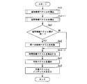
- FIG. 11 is a flowchart for explaining the operation of the prediction vector generation unit 110.
- the prediction vector determination unit 116 determines a prediction vector having a low coding cost from the additional candidate vectors and the basic candidate vectors (second candidate vector, third candidate vector) (Sc1).
- the prediction vector determination unit 116 also generates an index idx indicating the selection result in step Sc1.
- the index idx is an index indicating one of these three in total.
- the prediction vector determination unit 116 outputs the selected prediction vector Pv and the generated index idx (Sc2), and ends the process.
- the corresponding block is specified using the disparity vector generated by the disparity vector deriving unit 363, and the motion vector of the corresponding block or the generated disparity vector is used as an additional candidate vector for the prediction vector generation. .
- an additional candidate vector is always derived.
- the prediction vector generation unit 306 always generates all candidate vectors. However, since an index idx indicating which candidate vector is a prediction vector is input, it is useless to generate a candidate vector that is not indicated by the index idx. Therefore, in the present embodiment, when the index idx does not indicate an additional candidate vector, the additional candidate vector generation process is omitted, and when the index idx indicates an additional candidate vector, the second candidate vector, The process for acquiring the third candidate vector and the fourth candidate vector is omitted. As a result, useless candidate vector acquisition processing is eliminated, and the amount of processing related to generation of a prediction vector can be reduced.
- the image transmission system 10a in this embodiment includes an image decoding device 300a instead of the image decoding device 300.
- the image decoding device 300a is different from the image decoding device 300 only in that the prediction vector generation unit 306 is replaced with a prediction vector generation unit 306a.
- FIG. 12 is a schematic block diagram showing the configuration of the prediction vector generation unit 306a.
- the prediction vector generation unit 306a includes a vector prediction candidate derivation unit 361a and a prediction vector selection unit 368a.
- the vector prediction candidate derivation unit 361a includes an additional candidate vector derivation unit 362a and a basic candidate vector derivation unit 365a.
- the additional candidate vector deriving unit 362a includes a parallax vector deriving unit 363a and a motion vector deriving unit 364.
- the basic candidate vector deriving unit 365a includes a space candidate vector deriving unit 366a and a time candidate vector deriving unit 367a. Since the motion vector deriving unit 364 is the same as that shown in FIG.
- the disparity vector deriving unit 363a receives the index idx from the entropy decoding unit 301, and performs no processing when the index idx does not indicate an additional candidate vector (when it is 1 or more). When the index idx indicates an additional candidate vector (in the case of 0), processing similar to that performed by the disparity vector deriving unit 363 in FIG. 3 is performed.
- the spatial candidate vector deriving unit 366a receives the index idx from the entropy decoding unit 301, and performs no processing when the index idx indicates an additional candidate vector (in the case of 0). When the index idx does not indicate an additional candidate vector (when it is 1 or more), processing similar to that of the spatial candidate vector derivation unit 366 in FIG. 3 is performed.
- the time candidate vector deriving unit 367a receives the index idx from the entropy decoding unit 301, and performs no processing when the index indicates an additional candidate vector (in the case of 0). In this case, the processing amount can be reduced. When the index idx does not indicate an additional candidate vector (when it is 1 or more), the same processing as the time candidate vector deriving unit 115 in FIG. 3 is performed.
- the prediction vector selection unit 368a selects a prediction candidate vector with reference to the index idx in the same manner as the prediction vector selection unit 368.
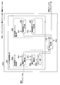
- FIG. 13 is a flowchart for explaining the operation of the prediction vector generation unit 306a.
- the same reference numerals (Sb1 to Sb4, Sb6) are assigned to portions corresponding to the respective portions in FIG. 7, and the description thereof is omitted.
- the prediction vector generation unit 306a determines whether the index indicates an additional candidate vector (Sd1). If the index indicates an additional candidate vector (Sd1-Yes), the process proceeds to the step of deriving the additional candidate vector in step Sb3. When the index does not indicate the additional candidate vector (Sd1-No), the derivation of the additional candidate vector is omitted and the process proceeds to step Sb4 for deriving the basic candidate vector.
- the prediction vector selection unit 368a selects a candidate vector from the value of the index idx acquired in step Sb1 and the candidate vector (Sd2).
- the spatial candidate vector derivation unit 366 generates the first spatial candidate vector from the block adjacent on the left side and the second spatial candidate vector from the block adjacent on the upper side. These two candidate vectors are likely to be the same vector because they are motion vectors or disparity vectors at spatially close positions. Therefore, in the present embodiment, the first space candidate vector and the second space candidate vector are checked for coincidence, and if they match, the second space candidate vector is deleted from the candidate vectors. Thereby, since redundant candidate vectors are deleted, the code amount of the index idx can be reduced.
- the image transmission system 10b in this embodiment includes an image decoding device 300b instead of the image decoding device 300, and includes an image encoding device 100b instead of the image encoding device 100.
- the image decoding apparatus 300b is different from the image decoding apparatus 300 only in that the prediction vector generation unit 306 is replaced with a prediction vector generation unit 306b.
- the image encoding device 100b is different from the image encoding device 100 only in that the prediction vector generation unit 110b is provided instead of the prediction vector generation unit 110.
- FIG. 14 is a schematic block diagram illustrating a configuration of the prediction vector generation unit 306b.
- the prediction vector generation unit 306b differs from the prediction vector generation unit 306 only in that the basic candidate vector derivation unit 365c has a candidate vector deletion unit 369b.
- the candidate vector deletion unit 369b checks whether the candidate vectors derived from the adjacent blocks generated by the spatial candidate vector deriving unit 366 match each other regardless of whether the target image is a reference viewpoint image or a non-reference viewpoint image. Do. In the match confirmation, the match of the prediction flags predFlagL0, predFlagL1, reference picture index refIdxL0, refIdxL1, vector mvL0, vector mvL0 is confirmed, and it is determined that they match if all match or some match. Specifically, a match confirmation between the first space candidate vector and the second space candidate vector is performed.
- the target image is a reference viewpoint image
- the first candidate vector (first space candidate vector) and the second candidate vector (second space candidate vector) are checked for coincidence, and the target image is a non-reference viewpoint image.
- the second candidate vector (first space candidate vector) matches the second candidate vector (first space candidate vector).
- the candidate vector deletion unit 369b When the two candidate vectors match, the candidate vector deletion unit 369b outputs the first space candidate vector to the prediction vector determination unit 368 and notifies that there is no second space candidate vector.
- the candidate vector deletion unit 369b outputs the first spatial candidate vector and the second spatial candidate vector to the prediction vector determination unit 368 when the two candidate vectors do not match. If the candidate vector deletion unit 369b is notified from the spatial candidate vector derivation unit 366 that either or both of the candidate vectors are not present, the candidate vector deletion unit 369b does not perform matching check and sends a similar notification to the prediction vector determination unit 368. Against.
- FIG. 15 is a flowchart for explaining the operation of the prediction vector generation unit 306b.
- steps Sb1, Sb3, Sb5 and Sb6 are the same as in FIG.
- the spatial candidate vector derivation unit 366 sets the motion vector Mv (spatial candidate vector) of the adjacent block as the second candidate vector and the third candidate vector (Sb4-1).
- the candidate vector deletion unit 369b determines whether or not the space candidate vectors match (Se1). If the space vector vectors match (Se1-Yes), one space candidate vector is deleted from the candidates (Se2). If the space candidate vectors do not match (Se1-No), the process proceeds to step Sb4-2.
- the temporal candidate vector derivation unit 367 acquires the motion vector Mv of the temporally adjacent block and sets it as the second candidate vector or the third candidate vector (Sb4-2). ).
- FIG. 16 is a schematic block diagram illustrating a configuration of the prediction vector generation unit 110b.
- the same reference numerals (362 to 367) are assigned to portions corresponding to the respective portions in FIG.
- the prediction vector determination part 116 is the same as that of the same part of FIG. 10, description is abbreviate
- the candidate vector deletion unit 369b is the same as the same unit in FIG.
- the predicted vector generation unit 110b includes an additional candidate vector derivation unit 362 and a basic vector derivation unit 365c.
- the basic vector deriving unit 365c includes a spatial candidate vector deriving unit 366, a temporal candidate vector deriving unit 367, a prediction vector determining unit 116, and a candidate vector deleting unit 369b.
- FIG. 17 is a flowchart for explaining the operation of the prediction vector generation unit 110b.
- step Sb3 is the same as that in FIG.
- Steps Sc1 and Sc2 are the same as those in FIG.
- Steps Se1, Se2, Sb4-1 and Sb4-2 are the same as in FIG.
- the candidate vector deletion unit 369b is not provided, and it is determined whether or not the already derived motion vector candidates match within the space candidate vector deriving unit 366 or the time candidate vector deriving unit 367.
- a configuration not derived as a candidate vector may be used.
- candidate vector deletion is performed by matching confirmation only between candidate vectors derived from adjacent blocks regardless of whether the target image is a reference viewpoint image or a non-reference viewpoint image. Therefore, when the target image is a non-reference viewpoint image, the amount of processing can be reduced compared to a configuration in which matching between an additional candidate vector and a candidate vector (spatial candidate vector) that is an element of a basic candidate vector is confirmed. it can.
- the additional candidate vector derivation unit in the first embodiment directly uses the motion vector of the corresponding block as the additional candidate vector.
- the additional candidate vector derivation unit derived in the case of the non-reference viewpoint image performs scaling processing on the motion vector of the corresponding block as necessary, and then sets the additional candidate vector.
- the image transmission system 10c in this embodiment includes an image decoding device 300c instead of the image decoding device 300, and includes an image encoding device 100c instead of the image encoding device 100.
- the image decoding device 300c is different from the image decoding device 300 only in that the prediction vector generation unit 306 is replaced with a prediction vector generation unit 306c.
- the image encoding device 100c is different from the image encoding device 100 only in that the prediction vector generation unit 110c is provided instead of the prediction vector generation unit 110.
- FIG. 18 is a schematic block diagram illustrating a configuration of the prediction vector generation unit 306c.
- the prediction vector generation unit 306c differs from the prediction vector generation unit 306 only in that the additional candidate vector derivation unit 362c has a scaling unit 370c.
- the scaling unit 370c determines whether the display order of the reference image of the target block and the reference image of the corresponding block are the same. If they are the same, the motion vector of the corresponding block is output to the prediction vector determination unit 116 as an additional candidate vector. If they are not the same, the motion vector of the corresponding block is scaled using the display order of the encoding target frame, the display order of the reference image of the target block, and the display order of the reference image of the corresponding block.
- Specific scaling methods include those described in Non-Patent Document 2 as follows.
- the display order of the encoding target frame is CurrPOC
- the display order of the reference image of the target block is RefPOC
- the display order of the reference image of the target block is ColRefPOC
- the motion vector of the corresponding block is Mv
- the motion vector of the corresponding block after scaling Mv ′ is derived as in the following formulas (1), (2), and (3). Abs () is a function that returns the absolute value of a given value.
- DistScaleFactor ((RefPOC-CurrPOC) x tx + 32) >> 64
- Mv ′ (DistScaleFactor ⁇ Mv) ⁇ ((Abs (DistScaleFactor ⁇ Mv) +127) >> 8)
- the scaling unit 370c outputs the scaled motion vector Mv ′ of the corresponding block to the prediction vector selection unit 368 as an additional candidate vector.
- FIG. 19 is a flowchart for explaining the operation of the additional candidate vector deriving unit 362c.
- steps Sa1 to Sa8 are the same as those in FIG.
- the scaling unit 370c determines whether the display order of the reference image of the target block and the reference image of the corresponding block are different (Sf1). If the display order of the reference images is different (Sf1-Yes), scaling is performed on the motion vector of the corresponding block (Sf2). If the display order of the reference images is not different (Sf1-No), the process proceeds to step Sa6.
- FIG. 20 is a schematic block diagram illustrating a configuration of the prediction vector generation unit 110c.
- the prediction vector generation unit 110c differs from the prediction vector generation unit 110 only in that the additional candidate vector derivation unit has a scaling unit 370c.
- the scaling unit 370c is the same as that in FIG.
- the derivation target vector is a motion vector
- the reference image of the target block and the reference of the corresponding block When the image display order (POC) is different, the prediction accuracy of the additional candidate vector is improved by scaling the motion vector of the corresponding block. Thereby, the code amount of the difference vector encoded by the difference between the prediction vector and the motion vector can be reduced.
- scalable coding high coding efficiency is realized by performing prediction between layers.
- a reference layer that does not perform prediction between layers is called a base layer, and other layers are called enhancement layers.
- the scalable coding includes spatial scalable (a picture with a base layer having a low resolution and an enhancement layer having a high resolution), SNR scalable (a picture with a base layer having a low image quality, and an enhancement layer having a high resolution), and the like.
- scalable encoding in particular, in encoding an enhancement layer picture, a base layer picture is used as a reference picture.
- each layer is composed of viewpoint images
- view scalable the case where each layer is composed of viewpoint images
- the reference viewpoint image corresponds to the base layer
- the non-reference viewpoint image corresponds to the enhancement layer. Therefore, the additional candidate vector derivation process in the first embodiment can be applied to each scalable coding scheme by regarding the reference viewpoint image as the base layer and the non-reference viewpoint image as the enhancement layer.
- the image transmission system 10d in this embodiment includes an image decoding device 300d instead of the image decoding device 300, and an image encoding device 100d instead of the image encoding device 100.
- FIG. 24 is a schematic block diagram showing the configuration of the image decoding device 300d.
- the image decoding apparatus 300d includes a prediction vector generation unit 306d instead of the prediction vector generation unit 306, a point where the addition result by the addition unit 304 is a motion vector Mv and a displacement vector Dv ′, and a result of addition by the addition unit 303 Is a decoded layer image Td ′, which is different from the image decoding device 300.
- the prediction vector generation unit 306d does not use the decoded depth map Dd
- the image decoding device 300d in FIG. 24 does not include the depth map decoding unit 309 and the depth map memory 310.
- the image decoding device 300d may include the depth map decoding unit 309, for example, when the decoding depth map Dd is used in the free viewpoint image display device 400.
- FIG. 25 is a schematic block diagram illustrating a configuration of the prediction vector generation unit 306d.
- the prediction vector generation unit 306d includes a displacement vector derivation unit 371d instead of the disparity vector derivation unit 363 and a motion vector derivation unit 364d instead of the motion vector derivation unit 364.
- the displacement vector deriving unit 371d receives the index idx from the entropy decoding unit 301, and performs no processing when the index idx does not indicate an additional candidate vector (when it is 1 or more). When the index idx indicates an additional candidate vector (in the case of 0), the following processing is performed.
- the displacement vector deriving unit 371d outputs the displacement vector to the motion vector deriving unit 364d when the reference image of the target block is the same layer as the target image, and the displacement vector deriving unit 368 when the reference image is a different layer. Output to. Whether or not the reference image and the target image are in the same layer is determined by whether or not the layer identifier layer_id, which is information for identifying which layer the target image belongs to, and the layer identifier relayer_id of the reference image are the same. Alternatively, as in the first embodiment, the determination is made based on whether the POC of each image is different or whether the reference image is a long-time reference picture.
- FIG. 26 is a conceptual diagram illustrating corresponding blocks in spatial scalability.
- the corresponding block is a block in the picture BR of the base layer including the coordinates xC ′ and yC ′ obtained from the following formula.
- xC ′ xC ⁇ (refW / picW)
- yC ′ yC ⁇ (refH / picH)
- refW and refH are the horizontal and vertical resolutions of the base layer, respectively.
- picW and picH are the horizontal and vertical resolutions of the enhancement layer, respectively.
- the displacement vector deriving unit 371d in FIG. 25 uses the coordinates xC and yC as starting points, a vector indicating the coordinates xC ′ and yC ′ as a displacement vector, and outputs the displacement vector to the motion vector deriving unit 364d.
- the motion vector deriving unit 364d specifies the corresponding block from the displacement vector, and acquires the motion vector mvLX of the corresponding block.
- the motion vector deriving unit 364d scales the acquired X component mvLX [0] and Y component mvLX [1] of the motion vector mvLX using the following equations.
- the motion vector deriving unit 364d outputs the scaled motion vector mvLX ′ to the prediction vector selecting unit 368.
- the motion vector deriving unit 364d outputs the zero vector to the prediction vector selecting unit 368 when the corresponding block is intra-coded.
- the displacement vector deriving unit 371d outputs a displacement vector that is a zero vector to the motion vector deriving unit 364d when the reference image of the target block is the same layer as the target image, and predicts the displacement vector when the reference image is a different layer.
- the data is output to the vector selection unit 368.
- the motion vector deriving unit 364d When the motion vector deriving unit 364d receives the displacement vector, the motion vector deriving unit 364d acquires, from the vector memory 305, the motion vector Mv of the corresponding block having the same coordinates as the target block in the base layer picture corresponding to the encoding target picture. The motion vector derivation unit 364d outputs the acquired motion vector Mv to the prediction vector selection unit 368. The motion vector deriving unit 364d outputs the zero vector to the prediction vector selecting unit 368 when the corresponding block is intra-coded.
- the spatial candidate vector deriving unit 366a receives the index idx from the entropy decoding unit 301, and performs no processing when the index idx indicates an additional candidate vector (in the case of 0). When the index idx does not indicate an additional candidate vector (when it is 1 or more), the same processing as the spatial candidate vector derivation unit 366a in FIG. 12 is performed, and the derived spatial candidate vector is output to the candidate vector deletion unit 369b. To do.
- the time candidate vector deriving unit 367a receives the index idx from the entropy decoding unit 301, and performs no processing when the index indicates an additional candidate vector (in the case of 0). When the index idx does not indicate an additional candidate vector (when it is 1 or more), the same processing as the time candidate vector derivation unit 367a in FIG. 12 is performed.
- the candidate vector deletion unit 369b confirms whether the candidate vectors derived from the adjacent blocks derived by the spatial candidate vector deriving unit 366a are matched regardless of whether the target image is a base layer or an enhancement layer.
- the prediction flags predFlagL0, predFlagL1, the reference picture indexes refIdxL0, refIdxL1, the vector mvL0, and the vector mvL0 are confirmed, and when all match or when a part matches, it is determined that they match.
- a match confirmation between the first space candidate vector and the second space candidate vector is performed.
- the target image is a base layer
- the first candidate vector (first space candidate vector) and the second candidate vector (second space candidate vector) are checked for coincidence
- the target image is an enhancement layer.
- the second candidate vector (first space candidate vector) and the third candidate vector (second space candidate vector) are checked for coincidence.
- the candidate vector deletion unit 369b When the two candidate vectors match, the candidate vector deletion unit 369b outputs the first space candidate vector and notifies the prediction vector selection unit 368 that there is no second space vector.
- the candidate vector deletion unit 369b outputs the first spatial candidate vector and the second spatial candidate vector to the prediction vector selection unit 368 when the two candidate vectors do not match.
- the candidate vector deletion unit 369b When the candidate vector deletion unit 369b is notified from the spatial candidate vector derivation unit 366a that there is no one or both candidate vectors, the candidate vector deletion unit 369b does not perform coincidence confirmation and sends a similar notification to the prediction vector selection unit 368. Against.
- FIG. 27 is a schematic block diagram showing the configuration of the image encoding device 100d.
- the image encoding device 100d includes a prediction vector generation unit 110d instead of the prediction vector generation unit 110, a point that an input image is a layer image T ′, and a prediction unit 107 that includes a motion vector Mv and a displacement vector Dv. Is different from the image coding apparatus 100 in that 'is input to the subtraction unit 108 and the vector memory 109.
- the prediction vector generation unit 110d does not use a depth map
- the image encoding device 100d in FIG. 27 does not include the depth map encoding unit 121 and the depth map memory 122.
- the image encoding device 100d may include the depth map encoding unit 121, such as when the decoding viewpoint map Dd is used in the free viewpoint image display device 400.
- FIG. 28 is a schematic block diagram illustrating a configuration of the prediction vector generation unit 110d.
- the prediction vector generation unit 110d is different from the prediction vector generation unit 110b in that it has a displacement vector derivation unit 371d instead of the disparity vector derivation unit 363 and a motion vector derivation unit 364d instead of the motion vector derivation unit 364. Since each part is the same as that of FIG. 25, description is abbreviate
- candidate vector deletion is performed by matching confirmation only between candidate vectors derived from adjacent blocks regardless of whether the target image is a base layer or an enhancement layer. Therefore, when the target image is an enhancement layer, the amount of processing can be reduced compared to a configuration in which matching between an additional candidate vector and a candidate vector (spatial candidate vector) that is an element of a basic candidate vector is confirmed.
- the disparity vector deriving unit 363e of the present embodiment limits blocks to be referred to in disparity vector acquisition according to the block size.
- the disparity vector deriving unit 363e of the present embodiment refers to the case where the number of blocks to be referenced is larger than the predetermined size when the size of the target block is equal to or smaller than the predetermined size. It should be smaller than the number of blocks to be used.
- the adjacent disparity vector deriving unit and the temporal disparity vector deriving unit do not refer to any of the blocks to be referenced when the block target is large.
- the adjacent disparity vector deriving unit refers to the blocks NBa0 and NBa1 adjacent to the left side of the target block and the blocks NBb0, NBb1 and NBb2 adjacent to the upper side of the target block.
- the disparity vector deriving unit 363e omits the operation of the adjacent disparity vector deriving unit.
- the pixels defining the blocks NBa0, NBa1, NBb0, NBb1, NBb2 correspond to the symbols A 0 , A 1 , B 0 , B 1 , B 2 in FIG. 4 and their coordinates (xPa0, yPa0), ( xPa1, yPa1), (xPb0, yPb0), (xPb1, yPb1), (xPb2, yPb2) are derived by the following equations.
- the temporal disparity vector deriving unit refers to two blocks of the block RB and the block Center when the block size is large, but a part of the block when the block size is small. Or, do not refer to all.
- the disparity vector deriving unit 363e omits the operation of the temporal disparity vector deriving unit.
- the disparity vector deriving unit 363e does not refer to the block of the image having a display order different from the display order (POC) of the image to which the target block belongs. That is, only the block of the image to which the target block belongs is set as a reference target. In this way, by changing the number of blocks to be referenced according to the block size, the processing amount related to the derivation of the prediction vector can be reduced, and further, the processing amount related to the decoding of the block can be reduced.
- the disparity vector deriving unit 363e of the present embodiment may use one of an adjacent disparity vector deriving unit described later and a temporal disparity vector deriving unit described later, or a combination thereof. That is, a configuration in which only the number of spatially adjacent blocks to be referred to is changed according to the block size, a configuration in which only the change in the number of temporally adjacent blocks to be referenced is changed, and a reference target In any configuration in which both the number of spatially adjacent blocks and the number of temporally adjacent blocks are changed, it is possible to reduce the processing amount related to the derivation of the prediction vector.
- the image transmission system 10e includes an image decoding device 300e instead of the image decoding device 300, and includes an image encoding device 100e instead of the image encoding device 100.
- FIG. 29 is a schematic block diagram showing the configuration of the image decoding device 300e.
- the image decoding apparatus 300e is different from the image decoding apparatus 300 in that the prediction vector generation unit 306 is replaced with a prediction vector generation unit 306e, and the entropy decoding unit 301 is replaced with an entropy decoding unit 301e.
- the image decoding device 300e in FIG. 29 does not include the depth map decoding unit 309 and the depth map memory 310.
- the image decoding device 300e may have the depth map decoding unit 309, such as when the decoding depth map Dd is used in the free viewpoint image display device 400.
- the entropy decoding unit 301e performs entropy decoding processing on the encoded stream Te.
- the difference from the entropy decoding unit 301 is that each block size (here, nPSW and nPSH, which are information indicating the horizontal and vertical widths) is derived from the separation result.
- the entropy decoding unit 301e outputs the horizontal width nPSW and vertical width nPSH of the block to the prediction vector generation unit 306e.
- the block is a prediction unit (PredictionUnit, PU) which is a unit for generating a prediction image, but may be a coding unit (Coding Unit, CU) including one or more prediction units.
- PredictionUnit PU
- CU coding unit
- the encoding unit is a unit that is a superordinate structure of a prediction unit that is a unit for generating a prediction image and a transform block (TransformUnit, TU) that is a unit for processing a prediction residual.
- the coding unit is also called a coding block (CodingCoBlock, CB).
- the picture is divided into coding tree units (Coding Tree Unit, CTU) of a predetermined size, and the coding tree unit is recursively divided into CUs having a quadtree structure.
- the CU is further divided into PUs. Whether or not to divide the coding tree unit into four CUs and whether or not to further divide the CU into four CUs are determined by a CU split flag (split_cu_flag) that is data included in the coded stream Te.
- split_cu_flag a CU split flag
- the horizontal width nPSW and vertical width nPSH of the block are not directly encoded as the data of the encoded stream Te, but the CU partition flag and PU partition mode of the encoding tree unit are decoded from the encoded stream Te.
- the block size may be processed by a combination of the CU size (nCbS) and the partition mode (PartMode) indicating the method of partitioning the CU into PUs instead of the block width nPSW and length nPSH.
- PartMode has values of 2N ⁇ 2N, 2N ⁇ N, N ⁇ 2N, and N ⁇ N. Each CU is divided into 1, 2, 2, and 4.
- the PU partition mode PartMode is 2N ⁇ 2N, 2N ⁇ N, N ⁇ 2N, N ⁇ N
- the PU sizes are nCbS ⁇ nCbS, nCbS ⁇ nCbS / 2, respectively. NCbSb / 2 ⁇ nCbS, nCbS ⁇ nCbS.
- FIG. 30 is a schematic block diagram illustrating a configuration of the prediction vector generation unit 306e.
- the prediction vector generation unit 306e is different from the prediction vector generation unit 306 in that it includes a disparity vector derivation unit 363e instead of the disparity vector derivation unit 363.
- the disparity vector deriving unit 363e is configured so that one or both of the adjacent disparity vector deriving unit and the temporal disparity vector deriving unit (not shown) generate a disparity vector having a configuration that does not use a depth map according to the first embodiment. It differs from the disparity vector deriving unit 363 described in FIG.
- the size determination of the target block is not limited to the sum of the horizontal width nPSW and the vertical width nPSH of the block, but one of the horizontal width nPSW and the vertical width nPSH, or the product of the horizontal width nPSW and the vertical width nPSH can also be used.
- the above-described predetermined constant for determining the block size and the block size used for the determination are the same in the determination by the adjacent disparity vector deriving unit described later.
- the adjacent parallax vector deriving unit when the block size is equal to or smaller than a predetermined size, for example, when the sum of the horizontal width nPSW and the vertical width nPSH of the block is equal to or less than a value M, the adjacent parallax
- the vector deriving unit first refers to a block to be referred to (block NBa0 in this case) among the blocks adjacent to the left side of the block in the disparity vector acquisition when the block size is large among the blocks adjacent to the left side of the block. Only the block to be referred to thereafter (for example, NBa1) is not referred to.
- the adjacent disparity vector deriving unit first selects a block (here, a block) to be referred to when the block size is large among the blocks adjacent to the upper side of the target block.
- a block here, a block
- blocks for example, NBb1 and NBb2
- the adjacent disparity vector deriving unit refers to all the blocks in order without performing the reference block restriction.
- the block NBb1 is located not only on the upper side but also on the upper right, and further on the upper right.
- the block NBb0 and the block NBb2 located at the upper left are also handled as blocks located above (upward) the target block.
- the block size When the block size is small, a plurality of reference blocks adjacent to each other often have the same prediction parameter (motion vector, reference picture index), and thus the effect of referring to the plurality of reference blocks is small.
- the block size When the block size is small, it is possible to reduce the processing amount without reducing the coding efficiency by reducing the blocks to be referred to.
- the block at the same position is set as a reference target (block NBa0, block NBb0), and when the block size is small, the block to be referred to may be limited. Is appropriate.
- the motion vector deriving unit 364 derives a motion vector based on the disparity vector derived by the disparity vector deriving unit 363e, and sets it as an additional candidate vector. Since serial dependent processing such as using the result of the disparity vector deriving unit 363e in the motion vector deriving unit 364 cannot be parallelized, the disparity vector acquisition as the previous processing is performed by, for example, the basic candidate vector deriving unit 365. Compared to the space candidate vector deriving unit 366 provided in FIG. That is, in the additional candidate vector deriving unit 362e (inter-view candidate vector deriving unit) that uses the motion information of the viewpoint image different from the target viewpoint image, it is appropriate to change the reference block according to the block size.
- the number of blocks to be referred to is changed by the spatial disparity vector deriving unit 366 and the adjacent disparity vector deriving unit included in the additional candidate vector deriving unit without depending on the block size. May be. That is, the number of blocks to be referenced by the spatial candidate vector deriving unit 366 that obtains the vector of the block adjacent to the target block is also the block adjacent to the target block used by the motion vector deriving unit 364 of the additional candidate vector deriving unit.
- the prediction vector generation unit 306 may be configured to reduce the number of blocks to be referred to by the adjacent disparity vector derivation unit that acquires the disparity vector.
- the space candidate vector deriving unit 366 uses the blocks NBa0 and NBa1 adjacent to the left side of the target block and the blocks NBb0, NBb1 and NBb2 adjacent to the upper side of the target block as reference targets, and the adjacent parallax vector deriving unit. Uses the block NBa0 adjacent to the left side of the target block and the block NBb0 adjacent to the upper side of the target block as reference targets.
- the adjacent parallax vector deriving unit when the block size is equal to or smaller than a predetermined size, for example, when the sum of the horizontal width nPSW and the vertical width nPSH of the block is equal to or smaller than a value M, the adjacent parallax The vector deriving unit refers only to the block adjacent to the left side of the block, and does not refer to the block adjacent to the upper side of the target block.
- the adjacent disparity vector deriving unit refers to all the blocks in order without performing the reference block restriction.
- the temporal disparity vector deriving unit in the present embodiment receives the block size from the entropy decoding unit 301e, and changes the reference block used for processing according to the block size.
- a predetermined size for example, when the sum of the horizontal width nPSW and the vertical width nPSH of the block is equal to or less than a value M, the lower right Only the block Rb adjacent to is referred to, and the block Center including the center coordinates of the target block is not referred to.
- the temporal disparity vector derivation unit When the block size is larger than the predetermined size, the temporal disparity vector derivation unit does not perform the reference block restriction, and the block Center including the center coordinates of the target block and the block RB adjacent to the lower right of the target block Both are referenced for the following.
- the temporal disparity vector derivation unit attempts to acquire a disparity vector in a reference picture having a reference picture index refIdxLX value of “0”.
- the temporal disparity vector deriving unit includes two blocks: a block RB adjacent to the lower right end of a block having the same coordinates as the target block in the reference picture, and a block Center including the center coordinates of the target block in the reference picture. Are checked in the order of the block RB and the block Center.
- the temporal disparity vector deriving unit is one block (here, block RB) that is referred to first among the blocks that may be referred to (blocks to be referred to). Only the block referred to thereafter (for example, the block Center) is not referred to.
- block RB the block RB
- the block RB and block Center are referred to when the block size is large, but the present invention is not limited to this example.
- a configuration in which one block is referred to when the block size is small and two or more blocks are referred to when the block size is large is included.
- the block Center may be referred to, and when the block size is large, the block RB and the block Center may be referred to in order.
- the block L positioned on the left of the block having the same coordinate as the target block or the block U positioned on the block having the same coordinate as the target block May be used.
- the coordinates of the pixels defining the block Center, the block RB, the block L, and the block U (xPc0, yPc0), (xPrb0, yPrb0), (xPl0, yPl0), (xPu0, yPu0) are expressed by the following equations. To derive.
- a pixel that defines a block is a pixel that must be included in the block.
- the block Center is a block including a pixel with coordinates (xPc0, yPc0).
- the temporal disparity vector deriving unit when the block size is equal to or smaller than a predetermined size, for example, when the sum of the horizontal width nPSW and the vertical width nPSH of the block is equal to or smaller than a value M, the temporal disparity The vector deriving unit does not refer to the blocks included in the reference pictures of different display orders in terms of time. That is, the operation of the temporal parallax vector deriving unit is omitted. Only when the block size is larger than the predetermined size, the temporal disparity vector deriving unit acquires the disparity vector of the block at the position corresponding to the target block of the block included in the reference picture in the temporally different display order. For example, a block Center including the center coordinates of the target block is referred to.
- a plurality of blocks may be referred to as follows.
- the disparity vectors are referred to in the order of the block RB and the block Center.
- the temporal disparity vector deriving unit outputs the disparity vector of the block confirmed to have first to the motion vector deriving unit 364. If the disparity vector is not included, the temporal disparity vector deriving unit notifies the inherent disparity vector deriving unit that there is no disparity vector.
- FIG. 31 is a schematic block diagram showing the configuration of the image encoding device 100e.
- the image encoding device 100e has an entropy encoding unit 103 instead of the entropy encoding unit 103, a prediction unit 107e instead of the prediction unit 107, and a prediction vector generation unit 110e instead of the prediction vector generation unit 110. This is different from the image encoding device 100.
- the image encoding device 100e in FIG. 31 does not include the depth map encoding unit 121 and the depth map memory 122.
- the image encoding device 100e may have the depth map encoding unit 121, for example, when the decoded viewpoint map Dd is used in the free viewpoint image display device 400.
- the entropy encoding unit 103e differs from the entropy encoding unit 103 in that the horizontal width nPSW and vertical width nPSH of the block output by the prediction unit 107e are also entropy encoded.
- the prediction unit 107e differs from the prediction unit 107 in that it generates a horizontal width nPSW and a vertical width nPSH of a block.
- the prediction unit 107e outputs the horizontal width nPSW and vertical width nPSH of the block to the entropy encoding unit 103e and the predicted vector generation unit 110e.
- the prediction vector generation unit 110e is different from the prediction vector generation unit 110 only in that it has a disparity vector derivation unit 363e instead of the disparity vector derivation unit 363.
- the block to be referred to by the adjacent parallax vector deriving unit and the temporal parallax vector deriving unit is determined based on the block size, for example, the horizontal width nPSW and the vertical width nPSH.
- the processing amount of the additional candidate vector deriving unit 362e can be reduced, and further, the processing amount related to block decoding can be reduced.
- the adjacent parallax vector deriving unit and the temporal parallax vector deriving unit change the block to be referred to based on the horizontal width nPSW and the vertical width nPSH of the block. Reference may be omitted in all the blocks referred to by the vector deriving unit. In this case, the process of the parallax vector acquisition unit can be omitted.
- FIG. 33 is a schematic block diagram showing the configuration of the image decoding device 300f.
- the image decoding device 300f is different from the image decoding device 300e in that it includes a prediction vector generation unit 306f instead of the prediction vector generation unit 306e.
- the predicted vector generation unit 306f does not use a depth map.
- the prediction vector generation unit 306f has a displacement vector derivation unit 371f instead of the disparity vector derivation unit 363e and a motion vector derivation unit 364d instead of the motion vector derivation unit 364. This is different from the unit 306e.
- the displacement vector deriving unit 371f receives the block size (horizontal width nPSW and vertical width nPSH) from the entropy decoding unit 301e, and when the block size is equal to or smaller than a predetermined size, for example, the sum of the horizontal width nPSW of the block and the vertical width nPSH is a value.
- the number of blocks to be referred to is made smaller than when the blocks are larger than a predetermined size.
- FIG. 35 is a schematic block diagram showing the configuration of the image encoding device 100f.
- the image encoding device 100f is different from the image encoding device 100e in that a prediction vector generation unit 110f is provided instead of the prediction vector generation unit 110e.
- the predicted vector generation unit 110f does not use a depth map.
- the prediction vector generation unit 110f has a displacement vector derivation unit 371f instead of the disparity vector derivation unit 363e, and a point having a motion vector derivation unit 364d instead of the motion vector derivation unit 364. Different from the vector generation unit 110.
- the block to be selected by the displacement vector deriving unit 371f is determined based on the horizontal width nPSW and vertical width nPSH of the block.
- the processing amount of the additional candidate vector deriving unit 362f can be reduced, and further, the processing amount related to block decoding can be reduced.
- each of the image decoding devices 300, 300x, 300a, 300b, 300c, 300d, 300e, and 300f the functions of each of the image decoding devices 300, 300x, 300a, 300b, 300c, 300d, 300e, and 300f, and the image encoding devices 100, 100b, 100c, 100d, 100e, and 100f in each embodiment, or a part of them.
- Each device may be realized by recording a program for realizing the above on a computer-readable recording medium, causing the computer system to read and execute the program recorded on the recording medium.
- the “computer system” includes an OS and hardware such as peripheral devices.
- the “computer-readable recording medium” means a storage device such as a flexible disk, a magneto-optical disk, a portable medium such as a ROM and a CD-ROM, and a hard disk incorporated in a computer system. Furthermore, the “computer-readable recording medium” dynamically holds a program for a short time like a communication line when transmitting a program via a network such as the Internet or a communication line such as a telephone line. In this case, a volatile memory in a computer system serving as a server or a client in that case, and a program that holds a program for a certain period of time are also included.
- the program may be a program for realizing a part of the functions described above, and may be a program capable of realizing the functions described above in combination with a program already recorded in a computer system.
- the image decoding devices 300, 300x, 300a, 300b, 300c, 300d, 300e, and 300f, and part or all of the image encoding devices 100, 100b, 100c, 100d, 100e, and 100f are typically integrated circuits. It may be realized as a certain LSI. Each functional block of each device may be individually made into a processor, or part or all may be integrated into a processor. Further, the method of circuit integration is not limited to LSI, and may be realized by a dedicated circuit or a general-purpose processor. In addition, when an integrated circuit technology that replaces LSI appears due to progress in semiconductor technology, an integrated circuit based on the technology can also be used.
- DESCRIPTION OF SYMBOLS 10 ... Image transmission system 100, 100b, 100c, 100d, 100e, 100f ... Image coding apparatus 101 ... Subtraction part 102 ... DCT transformation / quantization part 103, 103e ... Entropy coding part 104 ... Inverse quantization / inverse DCT transformation Unit 105 ... addition unit 106 ... reference image memory 107, 107e ... prediction unit 108 ... subtraction unit 109 ... vector memory 110, 110b, 110d, 110e ... prediction vector generation unit 116 ... prediction vector determination unit 121 ... depth map encoding unit 122 Depth map memory 200 ... Network 300, 300x, 300a, 300b, 300c, 300d, 300e, 300f ...
- Disparity vector derivation unit 364, 364d ... Motion vector derivation unit 365, 365a, 365c ... Basic Candidate vector derivation unit 366, 366a ... Spatial candidate vector derivation unit 367, 367a ... Temporal candidate vector derivation unit 368, 368a ... Prediction vector selection unit 369b . Candidate vector deletion unit 370c ... Scaling unit 371d, 3 71f ... Displacement vector deriving unit 400 ... Free viewpoint image display device
Landscapes
- Engineering & Computer Science (AREA)
- Multimedia (AREA)
- Signal Processing (AREA)
- Compression Or Coding Systems Of Tv Signals (AREA)
Abstract
非基準視点画像における対象ブロックの動きベクトルまたは視差ベクトルの予測ベクトルを生成する予測ベクトル生成装置であって、導出した視差ベクトルにより参照される他の視点画像における動きベクトル、または、前記導出した視差ベクトルを追加候補ベクトルとする追加候補ベクトル導出部と、対象ブロックに時間的および空間的に隣接する隣接ブロックに関するベクトルから1つ以上の候補ベクトル群を導出する基本候補ベクトル導出部と、前記追加候補ベクトルと、前記候補ベクトル群とのうちのいずれかを、インデックスに基づいて選択し、前記対象ブロックの予測ベクトルとする予測ベクトル選択部とを具備する。これにより、インデックスが追加候補ベクトルを示している場合のみ追加候補ベクトルを導出することで、追加候補導出の処理量を削減することができる。
Description
本発明は、予測ベクトル生成装置、画像符号化装置、および画像復号装置に関する。
動画像の符号化では、フレームをブロックに分割し、該ブロックに近い画像を、他のフレームから取得して予測画像とする動き予測が行われている。そして、このブロックに近い画像を示すベクトルを動きベクトルと呼び、当該ブロックの周辺のブロックの動きベクトルから当該ブロックの動きベクトルを予測することも行われている(例えば、非特許文献1、2、4を参照)。なお、動きベクトルの予測による得られるベクトルを、予測ベクトルという。
また、ISO(International Organization For Standardization)では、3次元映像符号の標準規格であり、複数の視点画像とデプスマップとを符号化する技術の規格化が行われている(非特許文献3)。
また、ISO(International Organization For Standardization)では、3次元映像符号の標準規格であり、複数の視点画像とデプスマップとを符号化する技術の規格化が行われている(非特許文献3)。
"Advanced video coding for generic audiovisual services",ITU-T H.264, March 2009
"High efficiency video coding (HEVC) text specification draft 7", Joint Collaborative Team on Video Coding (JCT-VC) of ITU-T SG16 WP3 andISO/IEC JTC1/SC29/WG11, 9th Meeting: Geneva, CH, 27 April - 7 May 2012, 2012, JCTVC-H1003 version 5
"3次元映像符号化の国際標準化動向", NTT技術ジャーナル, August 2011
"High efficiency video coding draft 8",JCTVC-J10003,Stockholm,SE,July,2012
しかしながら、複数の視点画像など、複数のレイヤを符号化する際には、前述の動きベクトルなどの動き情報を、符号化対象レイヤ(例えばベース視点画像)とは異なる参照レイヤ(例えば非ベース視点画像)の動き情報を用いて導出し、その動き情報を、ベースレイヤ画像(ベース視点画像)の符号化で用いられる予測候補とは、別に追加される追加予測候補として用いることが行われる。追加予測候補の導出では、符号化対象レイヤと、別の参照レイヤとの位置関係を示す変位ベクトル(視差ベクトル)の導出が必要になるため、その処理量が大きくなるという課題が有る。
本発明は、このような事情に鑑みてなされたもので、その目的は、追加予測候補導出の処理量を削減することができる予測ベクトル生成装置、画像符号化装置、および画像復号装置を提供することにある。
(1)この発明は上述した課題を解決するためになされたもので、本発明の一態様は、非基準視点画像における対象ブロックの動きベクトルまたは視差ベクトルの予測ベクトルを生成する予測ベクトル生成装置であって、前記対象ブロックの視差ベクトルを導出し、前記導出した視差ベクトルにより参照される、他の視点画像におけるブロックに関する動きベクトル、または、前記導出した視差ベクトルを候補ベクトルとする追加候補ベクトル導出部と、前記対象ブロックに時間的および空間的に隣接する隣接ブロックに関するベクトルから1つ以上の候補ベクトル群を導出する基本候補ベクトル導出部と、前記追加候補ベクトル導出部が導出する候補ベクトルと、前記基本候補ベクトル導出部が導出する候補ベクトル群とのうちのいずれかを、インデックスに基づいて選択し、前記対象ブロックの予測ベクトルとする予測ベクトル選択部とを具備し、前記追加候補ベクトル導出部は、インデックスが該追加候補ベクトル導出部が導出した候補ベクトルを示している場合のみ、候補ベクトルを導出することを特徴とする。
(2)また、本発明の他の態様は、(1)に記載の予測ベクトル生成装置であって、前記追加候補ベクトル導出部は、インデックスの値が0の場合に、インデックスが追加候補ベクトル導出部が導出した候補ベクトルを示していると判断することを特徴とする。
(3)また、本発明の他の態様は、(2)に記載の予測ベクトル生成装置であって、前記追加候補ベクトル導出部は、前記導出した視差ベクトルにより参照される他の視点画像におけるブロックが動きベクトルを有していなかった場合に、所定の固定ベクトルを追加候補ベクトルとすることを特徴とする。
(4)また、本発明の他の態様は、(3)に記載の予測ベクトル生成装置であって、前記追加候補ベクトル導出部は、所定の固定ベクトルとしてゼロベクトルを導出することを特徴とする。
(5)また、本発明の他の態様は、(1)から(4)のいずれかの項に記載の予測ベクトル生成装置を具備することを特徴とする画像復号装置である。
この発明によれば、追加予測候補導出の処理量を削減することができる。
[第1の実施形態]
以下、図面を参照して、本発明の第1の実施形態について説明する。図1は、この発明の第1の実施形態による画像伝送システム10の構成を示す概略ブロック図である。画像伝送システム10は、複数の視点画像とデプスマップとを符号化して伝送し、伝送先において、これらを用いた自由視点画像の表示を可能とするシステムである。図1に示すように、画像伝送システム10は、画像符号化装置100、ネットワーク200、画像復号装置300、自由視点画像表示装置400を含んで構成される。
以下、図面を参照して、本発明の第1の実施形態について説明する。図1は、この発明の第1の実施形態による画像伝送システム10の構成を示す概略ブロック図である。画像伝送システム10は、複数の視点画像とデプスマップとを符号化して伝送し、伝送先において、これらを用いた自由視点画像の表示を可能とするシステムである。図1に示すように、画像伝送システム10は、画像符号化装置100、ネットワーク200、画像復号装置300、自由視点画像表示装置400を含んで構成される。
画像符号化装置100は、複数の視点画像(テクスチャ画像ともいう)T各々を符号化し、視点画像T各々の符号化ストリームTeを生成する。さらに、画像符号化装置100は、符号化した視点画像T各々に対応するデプスマップDを符号化し、デプスマップ各々のデプスマップ符号化ストリームDeを生成する。ネットワーク200は、これらの符号化ストリームTeとデプスマップ符号化ストリームDeとを、画像復号装置300に伝送する、IP(Internet Protocol)ネットワーク、ケーブルテレビ網などのネットワークである。なお、符号化ストリームTeとデプスマップ符号化ストリームDeとは、本実施形態のようにネットワークにより伝送されてもよいが、地上デジタル放送、衛星放送などの放送波により伝送されてもよいし、DVD(Digital Versatile Disc)、ブルーレイ(Blu-ray(登録商標))などの記録媒体により伝送されてもよい。
画像復号装置300は、ネットワーク200が伝送した符号化ストリームTeとデプスマップ符号化ストリームDeとを復号し、復号視点画像Tdと復号デプスマップDdとを生成する。自由視点画像表示装置400は、画像復号装置300が生成した復号視点画像Tdおよび復号デプスマップDdを用いて、任意の視点からの画像を生成する。自由視点画像表示装置400は、液晶ディスプレイや、有機EL(electroluminescence)ディスプレイなどの表示デバイスを備え、生成した任意の視点からの画像を、該表示デバイスを用いて表示する。なお、この任意の視点からの画像は、2次元画像であってもよいし、立体画像であってもよい。
図2は、画像復号装置300の構成を示す概略ブロック図である。図2に示すように、画像復号装置300は、エントロピー復号部301、逆量子化・逆DCT変換部302、加算部303、加算部304、ベクトルメモリ305、予測ベクトル生成部306(予測ベクトル生成装置)、予測部307、参照画像メモリ308、デプスマップ復号部309、デプスマップメモリ310を含んで構成される。なお、予測ベクトル生成部306が、デプスマップを利用せずに、予測ベクトルを生成する構成の場合には、デプスマップ生成部311を備えない構成も可能である。
エントロピー復号部301は、エントロピー復号処理を、符号化ストリームTeに対して行う。エントロピー復号部301は、この復号処理の結果から、参照ピクチャインデックスrefIdx、インデックスidx、差分ベクトルΔv、量子化係数、予測モードを分離する。参照ピクチャインデックスrefIdxは、参照ピクチャを指定するためのインデックスである。予測画像が2つの予測ピクチャから生成可能な場合には、参照リストL0と、参照リストL1を用いて予測ピクチャを指定する。参照リストL0、参照リストL1の参照ピクチャインデックスはrefIdxL0、refIdxL1であり、参照リストL0、参照リストL1のインデックスidxは、mvp_l0_idx、mvp_l1_idxである。なお、参照リストL0、L1を区別しない場合には、refIdxLX(refIdx)、mvp_lX_idx(idx)と記載する。
逆量子化・逆DCT変換部302は、図2の逆量子化・逆DCT変換部104と同様の処理を、エントロピー復号部301が分離した量子化係数に対して逆量子化を行い、さらに、逆量子化した結果を逆DCT変換して、復号残差信号を生成する。加算部303は、逆量子化・逆DCT変換部302が生成した復号残差信号と、予測部307が生成した予測画像Pとを加算し、復号視点画像Tdを生成する。
加算部304は、エントロピー復号部301が分離した差分ベクトルΔvと、予測ベクトル生成部306が生成した予測ベクトルPvとを加算し、動きベクトルMvまたは視差ベクトルDvを生成する。加算部304は、生成した動きベクトルMvと視差ベクトルDvとを、ベクトルメモリ305に記憶させる。ベクトルメモリ305は、処理済み(符号化/復号済み)のブロックの予測パラメータ、例えば、動きベクトルMvと視差ベクトルDvとを記憶する。
具体的には、ベクトルメモリ305では、予測モードPredMode、予測フラグpredFlagL0、predFlagL1、参照ピクチャインデックスrefIdxL0、refIdxL1、ベクトルmvL0、mvL1を記憶する。predFlagL0、predFlagL1は、各参照リストL0、参照リストL1に属する参照ピクチャが予測画像生成に用いられるか否かを示す。ベクトルmvL0、mvL1は、動きベクトルMvもしくは視差ベクトルDvである。参照ピクチャインデックスrefIdxLXの示す参照ピクチャの表示順序が対象ブロックの表示順序と等しければ、ベクトルmvLXは視差ベクトル、異なれば、ベクトルmvLXは動きベクトルである(ここでXは0もしくは1)。
予測ベクトル生成部306は、エントロピー復号部301が分離した参照ピクチャインデックスrefIdx、インデックスidxを参照して、予測ベクトルPvを生成する。予測ベクトルPvの生成では、ベクトルメモリ305が記憶するベクトルと、デプスマップメモリ310が記憶する復号デプスマップDdとを参照する。なお、予測ベクトル生成部306の詳細については、後述する。
予測部307は、視点画像Tを分割したブロック各々の予測画像Pを生成する。予測部307は、各ブロックの予測画像Pを、エントロピー復号部301が分離した予測モードが示す予測方式を用いて生成する。なお、予測画像Pを生成する際の参照画像は、参照画像メモリ308から取得する。予測部307でイントラ予測により予測画像Pが生成されたブロックについては、イントラ予測を行い、予測画像Pを生成する。
予測モードが動き予測または視差予測を示していた場合には、予測部307は、ベクトルメモリ305が記憶している当該ブロックの参照ピクチャインデックスrefIdx、動きベクトルMvまたは視差ベクトルDvを用いた動き予測を行い、予測画像Pを生成する。
参照画像メモリ308は、加算部303が生成した復号視点画像Tdを参照画像として記憶する。デプスマップ復号部309は、デプスマップ符号化ストリームDeに対して復号処理行い、復号デプスマップDdを生成する。デプスマップメモリ310は、デプスマップ復号部309が生成した復号デプスマップDdを記憶する。
図3は、予測ベクトル生成部306の構成を示す概略ブロック図である。図3に示すように、予測ベクトル生成部306は、ベクトル予測候補導出部361、予測ベクトル選択部368を含んで構成される。ベクトル予測候補導出部361は、追加候補ベクトル導出部362、基本候補ベクトル導出部365を含んで構成される。
基本候補ベクトル導出部365は、対象画像が基準視点画像である場合も、非基準視点画像であるか否かに関わらず動作し、非基準視点画像および基準視点画像で用いられる1つ以上の予測ベクトルを導出する。空間候補ベクトル導出部366、時間候補ベクトル導出部367、図示しない固定ベクトル導出部を含んで構成される。
追加候補ベクトル導出部362は、非基準視点画像用の予測ベクトル(追加予測候補)を導出する。視差ベクトル導出部363、動きベクトル導出部364、図示しない固定ベクトル導出部を含んで構成される。追加候補ベクトル導出部362および内部の視差ベクトル導出部363、動きベクトル導出部364は対象画像が非基準視点画像である場合に限り動作する。
<デプスマップを利用する構成の視差ベクトルの生成>
視差ベクトル導出部363の一つの構成は、デプスマップを利用して視差ベクトルを導出する。視差ベクトル導出部363は、符号化対象のフレームに対応する復号デプスマップDd中の対象ブロックと同一座標のブロックのデプス値から視差ベクトルDvを生成する。視差ベクトル導出部363は、対象ブロックのベクトルが動きベクトルMvの場合には、生成した視差ベクトルDvを動きベクトル導出部364に出力する。視差ベクトル導出部363は、対象ブロックのベクトルが視差ベクトルDvの場合には、生成した視差ベクトルを追加候補ベクトルとして、予測ベクトル決定部368に出力する。なお、デプス値としては、該復号デプスマップDd中のブロックの中央の座標のデプス値を用いてもよいし、ブロック内の各画素のデプス値の平均値や最頻値、最大値、最小値を用いてもよい。
視差ベクトル導出部363の一つの構成は、デプスマップを利用して視差ベクトルを導出する。視差ベクトル導出部363は、符号化対象のフレームに対応する復号デプスマップDd中の対象ブロックと同一座標のブロックのデプス値から視差ベクトルDvを生成する。視差ベクトル導出部363は、対象ブロックのベクトルが動きベクトルMvの場合には、生成した視差ベクトルDvを動きベクトル導出部364に出力する。視差ベクトル導出部363は、対象ブロックのベクトルが視差ベクトルDvの場合には、生成した視差ベクトルを追加候補ベクトルとして、予測ベクトル決定部368に出力する。なお、デプス値としては、該復号デプスマップDd中のブロックの中央の座標のデプス値を用いてもよいし、ブロック内の各画素のデプス値の平均値や最頻値、最大値、最小値を用いてもよい。
図5は、視差ベクトル導出部363のデプスマップを利用する構成における動作を説明する概念図である。図5において、画像NBVは、非基準視点画像のあるフレームである。画像BVは、基準視点画像のあるフレームであり、画像NBVと同じ表示順序(POC)のフレームである。画像NBVDは、画像NBVに対応するデプスマップDdである。
符号Boは、画像NBVの対象ブロックであり、符号Bdは、基準視点画像BV中の対象ブロックと同一座標のブロックである。視差ベクトル導出部363は、対象ブロックBoに対応する復号デプスマップDdのブロックBdのデプス値をデプスマップメモリ122から読みだす。具体的には、対象ブロックBoと同じ座標の復号デプスマップDdのブロックBdのデプス値の平均値をデプス値として読み出す。視差ベクトル導出部363は、読みだしたデプス値の平均値を視差ベクトルDvに変換する。視差ベクトル導出部363は、導出対象ベクトルが視差ベクトルの場合には、視差ベクトルDvを追加候補ベクトルとする。なお、導出対象ベクトルは、参照ピクチャインデックス(refIdx)と、参照リスト(RefPicListX)で指定される参照ピクチャのPOCが、対象画像NBVのPOCと等しい場合には視差ベクトル、異なる場合には動きベクトルとなる。
符号Boは、画像NBVの対象ブロックであり、符号Bdは、基準視点画像BV中の対象ブロックと同一座標のブロックである。視差ベクトル導出部363は、対象ブロックBoに対応する復号デプスマップDdのブロックBdのデプス値をデプスマップメモリ122から読みだす。具体的には、対象ブロックBoと同じ座標の復号デプスマップDdのブロックBdのデプス値の平均値をデプス値として読み出す。視差ベクトル導出部363は、読みだしたデプス値の平均値を視差ベクトルDvに変換する。視差ベクトル導出部363は、導出対象ベクトルが視差ベクトルの場合には、視差ベクトルDvを追加候補ベクトルとする。なお、導出対象ベクトルは、参照ピクチャインデックス(refIdx)と、参照リスト(RefPicListX)で指定される参照ピクチャのPOCが、対象画像NBVのPOCと等しい場合には視差ベクトル、異なる場合には動きベクトルとなる。
<デプスマップを利用しない構成の視差ベクトルの生成>
視差ベクトル導出部363の別の構成はデプスマップを利用しないで視差ベクトルを導出する。この構成では、視差ベクトル導出部363は、まず、対象ブロックに隣接するブロックの視差ベクトルDvを取得する。視差ベクトル導出部363は図示しない隣接視差ベクトル導出部、時間視差ベクトル導出部、固定視差ベクトル導出部を備える。
視差ベクトル導出部363の別の構成はデプスマップを利用しないで視差ベクトルを導出する。この構成では、視差ベクトル導出部363は、まず、対象ブロックに隣接するブロックの視差ベクトルDvを取得する。視差ベクトル導出部363は図示しない隣接視差ベクトル導出部、時間視差ベクトル導出部、固定視差ベクトル導出部を備える。
視差ベクトル導出部363は、隣接視差ベクトル導出部において、対象ブロックの左側に隣接するブロックNBa0、NBa1の順で各ブロックの視差ベクトルの利用可能性を参照し、利用可能な視差ベクトルがある場合には、最初に参照したブロックの視差ベクトルを選択する。左に隣接するブロックのいずれにも利用可能な視差ベクトルがない場合には、隣接視差ベクトル導出部は、さらに、対象ブロックの上側に隣接するブロックNBb0、NBb1、NBb2の順で各ブロックの視差ベクトルの利用可能性を参照し、利用可能な視差ベクトルがある場合には、最初に参照したブロックの視差ベクトルを選択する。
隣接するブロック関連する視差ベクトルがない場合、視差ベクトル導出部363の備える時間視差ベクトル導出部は、時間的に別の表示順の参照ピクチャに含まれるブロックの対象ブロックに対応する位置のブロックの視差ベクトルを取得する。
隣接視差ベクトル導出部、時間視差ベクトル導出部において視差ベクトルが取得できない場合、視差ベクトル導出部363は、固定視差ベクトル取得部において、第1候補ベクトルをゼロベクトルとする。
隣接視差ベクトル導出部、時間視差ベクトル導出部において視差ベクトルが取得できない場合、視差ベクトル導出部363は、固定視差ベクトル取得部において、第1候補ベクトルをゼロベクトルとする。
<視差ベクトルおよび動きベクトルの参照>
なお、視差ベクトル導出部363は、あるブロックX(Xは上記ブロックの一つ)の動きベクトルおよび視差ベクトルを次のように参照する。ブロックXの予測モードpredModeもしくはブロックXの2つの予測フラグpredFlagL0、predFlagL1を参照し、ブロックXがインター予測されているか否かをチェックする。予測モードpredModeがMODE_INTRAであればイントラ予測、それ以外であればインター予測である。予測フラグpredFlagL0、predFlagL1は、各参照リストL0、参照リストL1に属する参照ピクチャが予測画像生成に用いられるか否かを示す。予測フラグpredFlagL0、predFlagL1がともに1であればインター予測の双予測、いずれか一方のみが1であればインター予測の単予測、ともに0であればイントラ予測である。
なお、視差ベクトル導出部363は、あるブロックX(Xは上記ブロックの一つ)の動きベクトルおよび視差ベクトルを次のように参照する。ブロックXの予測モードpredModeもしくはブロックXの2つの予測フラグpredFlagL0、predFlagL1を参照し、ブロックXがインター予測されているか否かをチェックする。予測モードpredModeがMODE_INTRAであればイントラ予測、それ以外であればインター予測である。予測フラグpredFlagL0、predFlagL1は、各参照リストL0、参照リストL1に属する参照ピクチャが予測画像生成に用いられるか否かを示す。予測フラグpredFlagL0、predFlagL1がともに1であればインター予測の双予測、いずれか一方のみが1であればインター予測の単予測、ともに0であればイントラ予測である。
ブロックXがインター予測されていない場合には、ブロックXの動きベクトルおよび視差ベクトルは利用可能ではない。参照リストLXの予測フラグpredFlagLXが1の場合には、予測画像生成に用いる参照ピクチャが、参照ピクチャインデックスrefIdxLXにより指定される。ブロックXがインター予測である場合には、次に、対象ブロックの参照ピクチャインデックスrefIdxLXが示す参照ピクチャの時間順序(POC)と、ブロックXの参照ピクチャインデックスrefIdxLXが示す参照ピクチャの時間順序(POC)を比較する(X=0もしくは1)。具体的には、以下の2つを比較する。
PicOrderCnt( RefPicListX[ refIdxLX ] )
PicOrderCnt( RefPicListX[ refIdxLX of blockX ] )
PicOrderCnt( RefPicListX[ refIdxLX ] )
PicOrderCnt( RefPicListX[ refIdxLX of blockX ] )
ここで、RefPicListXは参照ピクチャインデックスredIdxLXから参照ピクチャを参照するための配列、PicOrderCnt(x)は引数xで指定された参照ピクチャの表示順序を求める関数である。なお、対象ブロックのL0リスト用の参照ピクチャインデックスrefIdxL0に対しては、ブロックXのL0リスト用の参照ピクチャインデックスrefIdxL0と参照リストL0用のベクトルを参照するが、ブロックXの参照リストL1用の参照ピクチャインデックスref_L1idxと参照リストL0用のベクトルを参照しても良い。対象ブロックの参照リストL1用の参照ピクチャインデックスrefIdxL1も同様である。
上記、時間順序が異なる場合には、ベクトルメモリで保持されているブロックXのベクトルmvLXは動きベクトルであり、動きベクトルが利用可能であり、動きベクトルが導出される。
逆に、上記、時間順序が等しい場合には、ベクトルメモリで保持されているブロックXのベクトルmvLXは視差ベクトルであり、視差ベクトルが利用可能であり、視差ベクトルが導出される。
逆に、上記、時間順序が等しい場合には、ベクトルメモリで保持されているブロックXのベクトルmvLXは視差ベクトルであり、視差ベクトルが利用可能であり、視差ベクトルが導出される。
動きベクトル導出部364は、視差ベクトル導出部363が生成した視差ベクトルDvを参照して、該視差ベクトルDvが示す他の視点画像におけるブロック(対応ブロックともいう)を選択し、該ブロックが有する動きベクトルMvをベクトルメモリ305から読み出す。動きベクトル導出部364は、読み出した動きベクトルMvを追加候補ベクトルとして、予測ベクトル決定部368に通知する。
より具体的には、上述の対応ブロックは、動きベクトル導出部364が取得する動きベクトルMvは、対象ブロックの中心点を起点にしたときに、視差ベクトル導出部363が生成した視差ベクトルDvが示す点を含むブロックである。なお、視差ベクトルDvが示す点の座標は、起点の座標に視差ベクトルDvを加算した座標である。また、対応ブロックは、対象ブロックが属するフレームと同じ表示順序の視差ベクトルDvが参照している別視点の視点画像のフレームに属する。
図5を参照すると、対象ブロックBoに対応する画像BV上のブロックBp(対応ブロックともいう)が有する動きベクトルMvcをベクトルメモリ109から読み出し、追加候補ベクトルとする。なお、対応ブロックBpは、対象ブロックBoの中心Cnと同じ座標の、基準視点画像における点Cbを起点としたときに、視差ベクトルDvが示す点を含むブロックにより求める。ここで、ブロックBpの予測画像が、動き予測ではなく、イントラ予測により生成されていた場合には、ブロックBpは動きベクトルを有していない。
追加候補ベクトル導出部362は、追加候補ベクトルとして、視差ベクトル導出部363および動きベクトル導出部364において候補ベクトルが導出されない場合には、図示しない固定ベクトル導出部において所定の固定ベクトルを追加候補ベクトルとする。上記処理により、追加候補ベクトル導出部362は、候補ベクトルを導出する。所定の固定ベクトルとしては、ゼロベクトルが適当である。
なお、ゼロベクトルの導出は以下の式で表現できる。
mvpListLX[ depthCandIdx ][ 0 ] = 0
mvpListLX[ depthCandIdx ][ 1 ] = 0
ここで、mvpListLX[i][j]は、リストインデックスi、方向jのリストLX(Xは0もしくは1)の予測ベクトル候補の動きベクトルを示す。リストインデックスiは、予測ベクトル候補の順序を示す。本実施形態では、追加候補ベクトルが第1候補であり、depthCandIdx=0である。なお、j=0はX方向動きベクトル、j=1はY方向動きベクトルを示す。
以上の構成により、追加候補ベクトルが導出される。
<基本候補ベクトルの導出>
mvpListLX[ depthCandIdx ][ 0 ] = 0
mvpListLX[ depthCandIdx ][ 1 ] = 0
ここで、mvpListLX[i][j]は、リストインデックスi、方向jのリストLX(Xは0もしくは1)の予測ベクトル候補の動きベクトルを示す。リストインデックスiは、予測ベクトル候補の順序を示す。本実施形態では、追加候補ベクトルが第1候補であり、depthCandIdx=0である。なお、j=0はX方向動きベクトル、j=1はY方向動きベクトルを示す。
以上の構成により、追加候補ベクトルが導出される。
<基本候補ベクトルの導出>
基本候補ベクトル導出部362の備える空間候補ベクトル導出部366は、対象ブロックに隣接する隣接ブロックが有するベクトル(動きベクトルMvまたは視差ベクトルDv)を、ベクトルメモリ305から読み出し、空間候補ベクトルとして予測ベクトル決定部368に通知する。空間候補ベクトル導出部366は、1つもしくは複数の隣接ブロックからベクトル(動きベクトルMvまたは視差ベクトルDv)を読み出し、1つ以上の空間候補ベクトルとして、予測ベクトル決定部368に通知する。空間候補ベクトル導出部366は、対象ブロックのベクトルが動きベクトルMvであり、隣接ブロックが視差ベクトルDvを有していた場合には、候補ベクトルが無いことを予測ベクトル決定部368に通知する。対象ブロックが視差ベクトルDvで隣接ブロックが動きベクトルMvを有する場合も同様である。本実施形態では、隣接ブロックは対象ブロック左側と上側の2つであるので、候補ベクトルは最大で2つであるが、その他の数であってもよい。
図4は、空間候補ベクトル導出部366の動作を説明する概念図である。図4において、符号Boは、対象ブロックであり、符号A0、A1、B0、B1、B2が付された矩形は、対象ブロックBoの隣接ブロックである。空間候補ベクトル導出部366は、隣接ブロックA0が動きベクトルまたは視差ベクトルを有しおり、なお且つ、隣接ブロックA0が有しているベクトルが対象ブロックのベクトルと同じ種類であった場合には、隣接ブロックA0の動きベクトルまたは視差ベクトルを第1空間候補ベクトルとする。隣接ブロックA0が動きベクトルまたは視差ベクトルを有していない、または、隣接ブロックA0が有しているベクトルと対象ブロックのベクトルが異なる種類であった場合には、次に、隣接ブロックA1に対して同様の処理を行う。隣接ブロックA1も適当な動きベクトルまたは視差ベクトルを有していない場合には、第1空間候補ベクトルが無いことを予測ベクトル決定部368に通知する。
さらに、空間候補ベクトル導出部366は、隣接ブロックB0に対しても同様の処理を行い、第3候補ベクトルを設定する。隣接ブロックB0が適用なベクトルを有していない場合には、隣接ブロックB1、B2の順に同様の処理を行う。隣接ブロックB1、B2も適用なベクトルを有していない場合には、第2空間候補ベクトルが無いことを予測ベクトル決定部368に通知する。
第1空間候補と第2空間候補ベクトルは、対象画像が基準視点画像の場合には、第1候補ベクトルおよび第2候補ベクトルとして導出され、対象画像が非基準視点画像の場合には、第2候補ベクトルおよび第3候補ベクトルとして導出される。なお、非特許文献2にあるように、各隣接ブロックの動きベクトルまたは視差ベクトルに対してスケーリング処理を行ったベクトルを候補ベクトルとしてもよい。
第1空間候補と第2空間候補ベクトルは、対象画像が基準視点画像の場合には、第1候補ベクトルおよび第2候補ベクトルとして導出され、対象画像が非基準視点画像の場合には、第2候補ベクトルおよび第3候補ベクトルとして導出される。なお、非特許文献2にあるように、各隣接ブロックの動きベクトルまたは視差ベクトルに対してスケーリング処理を行ったベクトルを候補ベクトルとしてもよい。
基本候補ベクトル導出部362の備える時間候補ベクトル導出部367は、符号化対象のフレームと同一視点の参照画像から、対象ブロックと同一座標のブロックが有する動きベクトルMvまたは視差ベクトルDvを、ベクトルメモリ109から読み出し時間候補ベクトルを導出する。ここでは、第1空間候補ベクトルもしくは第2空間候補ベクトルが存在しない。もしくは、第1空間候補ベクトルと第2空間候補ベクトルが一致する場合に限り、時間候補ベクトルを導出する。空間候補ベクトル導出部366は、読み出した動きベクトルMvまたは視差ベクトルDvを、時間候補ベクトルとして、予測ベクトル決定部368に通知する。なお、同一座標のブロックだけではなく、該ブロックに隣接するブロックが有する動きベクトルMvまたは視差ベクトルDvを候補ベクトルとしてもよい。また、導出対象が動きベクトルMvであり、対応するブロックのベクトルが視差ベクトルDvの場合には、時間候補ベクトルが無いことを予測ベクトル決定部368に通知する。導出対象ベクトルが視差ベクトルDvであり、対応するブロックのベクトルが動きベクトルMvである場合も同様である。
予測ベクトル選択部368は、インデックスidxを参照して、各候補ベクトルから予測候補ベクトルを選択する。対象画像が基準視点画像の場合には、基本候補ベクトル導出部365から導出される候補ベクトルから予測候補ベクトルを選択し、対象画像が非基準視点画像の場合には、追加候補ベクトル導出部362と基本候補ベクトル導出部365からの入力される候補ベクトルから、予測ベクトルを選択する。選択された予測ベクトルは、予測ベクトルPvとして加算部304に出力する。
対象画像が非基準視点画像の場合には、予測ベクトル選択部368は、インデックスidxの値が0の時は追加候補ベクトルを、1の時は基本候補ベクトル選択する。ただし、各候補ベクトルが無いことが通知された場合には、無いことが通知された候補ベクトル以降の候補ベクトルを示すインデックスidxの値を1つ繰り下げる。例えば、第1候補ベクトルが無いことが通知された場合には、インデックスidxの値1において、第2候補ベクトルを選択する。
<追加候補ベクトル導出部362の動作>
<追加候補ベクトル導出部362の動作>
図6は、追加候補ベクトル導出部362の動作を説明するフローチャートである。図6に示すフローチャートが示す処理は、動き予測により予測画像を生成する1つの対象ブロックに対する追加候補ベクトル導出部362の処理である。視差ベクトル導出部363は、デプスマップを利用する構成の場合には、符号化対象のフレームに対応する復号デプスマップDd中の対象ブロックと同一座標のブロックのデプス値をデプスマップメモリ310から取得する(Sa1)。デプスマップを利用しない構成の場合は、デプス値を導出しない。視差ベクトル導出部363は、視差ベクトルを導出する(Sa2)。デプスマップを用いる構成の場合には、前ステップで導出したデプス値を視差ベクトルに変換する。視差ベクトル導出部363は、導出対象のベクトルが動きベクトルであるか(動き予測)、視差ベクトルであるか(視差予測)を判定する(Sa3)。動き予測で生成されている場合には(Sa3-Yes)、動きベクトル導出部364に視差ベクトルDvを出力し、ステップSa4に進む。動き予測で生成されていない場合には(Sa3-No)、視差ベクトルDvを追加候補ベクトルとし(Sa8)、処理を終了する。
動きベクトル導出部364は、視差ベクトルDvから他の視点画像における対応ブロックを特定する(Sa4)。動きベクトル導出部364は、特定した対応ブロックに動きベクトルが在るか否かを判定する(Sa5)。在ると判定したときは(Sa5-Yes)、動きベクトル導出部364は、該動きベクトルをベクトルメモリ109から取得し、追加候補ベクトルとし(Sa6)、処理を終了する。一方、ステップSa5にて無いと判定したときは(Sa5-No)、固定ベクトル(ここではゼロベクトル)を追加候補ベクトルとし(Sa7)、処理を終了する。
図7は、予測ベクトル生成部306の動作を説明するフローチャートである。まず、予測ベクトル生成部306は、エントロピー復号部301が分離した対象ブロックの参照ピクチャインデックス(参照ピクチャインデックスrefIdxL0、refIdxL1)と、インデックスidxを取得する(Sb1)。次に、対象画像が、基準視点画像であるか、非基準視点画像であるかを判定する(Sb2)。対象画像が、非基準視点画像である場合には、追加候補ベクトル導出部362が図6に示す処理を行い、追加候補ベクトルを決定する(Sb3)。
対象画像が、非基準視点画像もしくは基準視点画像であるである場合には、以下の処理により基本候補ベクトルを導出する(Sb4)。対象画像が基準視点画像である場合には、基本候補ベクトル導出部365において、第1候補ベクトル~第2候補ベクトルを導出する。まず、空間候補ベクトル導出部366は、隣接ブロックの動きベクトルMvを第1候補ベクトルおよび第2候補ベクトルとする。次に、時間候補ベクトル導出部367は、第1候補ベクトル(第1空間候補ベクトル)が存在しない場合には、時間隣接ブロックの動きベクトルMvを取得し、第1候補ベクトルとする。
また、第1候補ベクトル(第1空間候補ベクトル)と第2候補ベクトル(第2空間候補ベクトル)が等しい場合には、時間隣接ブロックの動きベクトルMvを取得し、第2候補ベクトルとする。対象画像が非基準視点画像である場合には、基本候補ベクトル導出部365で、第2候補ベクトルと第3候補ベクトルを導出する。すなわち、空間候補ベクトル導出部366が、隣接ブロックの動きベクトルMvまたは視差ベクトルDvを取得し、第2候補ベクトルおよび第3候補ベクトルとする。次に、時間候補ベクトル導出部367は、第2候補ベクトル(第1空間候補ベクトル)が存在しない場合には、時間隣接ブロックの動きベクトルMvを取得し、第2候補ベクトルとする。また、第2候補ベクトル(第1空間候補ベクトル)と第3候補ベクトル(第2空間候補ベクトル)が等しい場合には、時間隣接ブロックの動きベクトルMvを取得し、第3候補ベクトルとする。
次に、予測ベクトル決定部368は、インデックスidxに従って予測ベクトルを選択する(Sb5)。対象画像が、非基準視点画像である場合には、追加候補ベクトル(第1候補ベクトル)と基本候補ベクトル(第2候補ベクトル、第3候補ベクトル)の中から予測ベクトルを選択する。対象画像が、基準視点画像である場合には、基本候補ベクトル(第1候補ベクトルと第2候補ベクトル)の中から予測ベクトルを選択する。
次に、予測ベクトル選択部368は、ステップSb5にて選択されたベクトルを予測ベクトルPvとして加算部304に出力する(Sb6)。
次に、予測ベクトル選択部368は、ステップSb5にて選択されたベクトルを予測ベクトルPvとして加算部304に出力する(Sb6)。
以上の構成では、追加候補ベクトル導出部362は、追加候補ベクトルを必ず生成する。すなわち、追加候補ベクトル導出部362において、デプスマップから導出する方法および隣接ブロックから導出する方法において、追加候補ベクトルとして、視差ベクトルおよび動きベクトルが得られない場合に、追加候補ベクトルとして所定の固定ベクトルを用いる。
この構成では、対象画像が非基準視点画像である場合に、インデックスidxが0のときは、予測ベクトルは追加候補ベクトル導出部362が生成した追加候補ベクトルであり、インデックスidxが1以上のときは、予測ベクトルは基本候補ベクトル導出部365が生成した候補ベクトルである。
この構成では、対象画像が非基準視点画像である場合に、インデックスidxが0のときは、予測ベクトルは追加候補ベクトル導出部362が生成した追加候補ベクトルであり、インデックスidxが1以上のときは、予測ベクトルは基本候補ベクトル導出部365が生成した候補ベクトルである。
追加候補ベクトルを必ず生成する構成では、インデックスidxにより、予測ベクトルが追加候補ベクトルであるか、基本候補ベクトルであるかが識別することができるため、インデックスidxが基本候補ベクトルを示す場合に、追加候補ベクトル導出処理を行うことや、逆に、インデックスidxが追加候補ベクトルを示す場合に、基本候補ベクトル導出処理を行うことを防ぎ、候補ベクトルの導出処理を簡略化することができる。
より詳細には、視差ベクトル導出部363と、空間候補ベクトル導出部366が同時に動作することを防ぐことができ、動きベクトル導出部364と、空間候補ベクトル導出部366が同時に動作することを防ぐことができる。また、視差ベクトル導出部363と、時間候補ベクトル導出部367が同時に動作することを防ぐことができ、動きベクトル導出部364と、時間候補ベクトル導出部367が同時に動作することを防ぐことができる。
より詳細には、視差ベクトル導出部363と、空間候補ベクトル導出部366が同時に動作することを防ぐことができ、動きベクトル導出部364と、空間候補ベクトル導出部366が同時に動作することを防ぐことができる。また、視差ベクトル導出部363と、時間候補ベクトル導出部367が同時に動作することを防ぐことができ、動きベクトル導出部364と、時間候補ベクトル導出部367が同時に動作することを防ぐことができる。
なお、図22の構成は、追加候補ベクトルを必ず生成する構成では、インデックスidxにより、予測ベクトルが追加候補ベクトルであるか、基本候補ベクトルであるかを識別することができるため、予測ベクトルが追加候補ベクトルであるか、基本候補ベクトルであるかが識別するフラグをインデックスidxとして用いる後述の図22の構成が可能である。
<符号化データ構成と予測ベクトル決定部368の動作>
<符号化データ構成と予測ベクトル決定部368の動作>
インデックスidxの符号化データの構成として、幾つかの構成を構成しうる。ここでは、3つの構成例と、それに対応する予測ベクトル決定部368および追加候補ベクトル導出部362の動作を説明する。なお、本構成は、後述の実施形態2~実施形態4においても使用可能である。
図21(a)は、インデックスidxの符号化方法を示す第1の符号化データ構成を示す図である。第1の符号化データ構成は、これまで説明したインデックスidxの構成であり、予測候補ベクトルのインデックスidxとして、基準画像である場合(図のbaseView(ref_idx_l0[x0][y0])が真)、0か1の2値をとるmvp_lX_flagを含み、非基準画像である場合、0~2の3値をとるmvp_lX_idxを含む。mvp_lX_flagはエントロピー復号部301において復号される。
図21(a)は、インデックスidxの符号化方法を示す第1の符号化データ構成を示す図である。第1の符号化データ構成は、これまで説明したインデックスidxの構成であり、予測候補ベクトルのインデックスidxとして、基準画像である場合(図のbaseView(ref_idx_l0[x0][y0])が真)、0か1の2値をとるmvp_lX_flagを含み、非基準画像である場合、0~2の3値をとるmvp_lX_idxを含む。mvp_lX_flagはエントロピー復号部301において復号される。
図21(b)は、第1の符号化データ構成におけるインデックスidxと、候補ベクトルの関係を示す図である。対象画像が基準視点画像の場合には、インデックスは2値をとるmvp_lX_flagであり、mvp_lX_flagが0の場合には基本候補ベクトル1、mvp_lX_flagが1の場合には基本候補ベクトル2が対応する。対象画像が非基準視点画像の場合には、インデックスは3値をとるmvp_lX_idxであり、mvp_lX_idxが0の場合には、追加候補ベクトル、mvp_lX_idxが1の場合には、基本候補ベクトル1、mvp_lX_flagが2の場合には基本候補ベクトル2が対応する。
ベクトル予測候補導出部361は、対象画像が基準視点画像である場合、及び、対象画像が非基準視点画像で、mvp_lX_idxが1か2の場合に、基本候補ベクトル導出部365において、基本候補ベクトル1と基本候補ベクトル2を導出する。逆に、対象画像が非基準視点画像で、mvp_lX_idxが0の場合に、追加候補ベクトル導出部362において追加候補ベクトルを導出する。予測ベクトル選択部368は、図21(b)の対応関係に従い予測候補ベクトルを選択する。
図21の構成によれば、対象画像が基準視点画像か非基準視点画像であるかによって、値域の異なるシンタックス要素を切り替えることによって、インデックスidxを導出する。対象画像が基準視点画像である場合の2値のシンタックス要素は、3Dではない(2Dの)符号化データの構成と同一であるため、2Dの符号化データと3Dの符号化データの両方に対応した復号装置の実装が容易になる。
図22(a)は、インデックスの符号化方法を示す第3の符号化データ構成を示す図である。第2の符号化データ構成では、予測候補ベクトルのインデックスidxとして、基準画像である場合(図のbaseView(ref_idx_l0[x0][y0])が真)、mvp_lX_flagを含み、非基準画像である場合、mvp_lX_flagとmvp_ex_lX_flagを含む。mvp_lX_flag とmvp_ex_lX_flagは共に2値である。mvp_lX_flag、mvp_ex_lX_flagはエントロピー復号部301において復号される。
図22(b)は、第2の符号化データ構成におけるインデックスidxと、候補ベクトルの関係を示す図である。mvp_ex_lX_flagが0の場合で、mvp_lX_flagが0の場合には基本候補ベクトル1、mvp_lX_flagが1の場合には基本候補ベクトル2が対応する。mvp_ex_lX_flagが1の場合には、追加候補ベクトルが対応する。
エントロピー復号部301は、対象画像が基準視点画像である場合に、符号化データを復号せずにmvp_ex_lX_flagとして0を導出(infered)し、対象画像が非基準視点画像の場合には、復号データからmvp_ex_lX_flagを復号する。さらにエントロピー復号部301は、mvp_ex_lX_flagが0の場合にmvp_lX_flagを復号する。
エントロピー復号部301は、対象画像が基準視点画像である場合に、符号化データを復号せずにmvp_ex_lX_flagとして0を導出(infered)し、対象画像が非基準視点画像の場合には、復号データからmvp_ex_lX_flagを復号する。さらにエントロピー復号部301は、mvp_ex_lX_flagが0の場合にmvp_lX_flagを復号する。
ベクトル予測候補導出部361は、対象画像が基準視点画像である場合、及び、対象画像が非基準視点画像でありmvp_ex_lX_flagが0の場合に、基本候補ベクトル導出部365において、基本候補ベクトル1と基本候補ベクトル2を導出する。逆に、対象画像が非基準視点画像で、mvp_ex_lX_flagが1の場合に、追加候補ベクトル導出部362において追加候補ベクトルを導出する。予測ベクトル選択部368は、図22(b)の対応関係に従い予測候補ベクトルを選択する。また、図22の構成は、基本候補ベクトルと追加候補ベクトルの一致判定による削除を行わない第3の実施形態で用いることも好適である。
この場合、基本候補ベクトルが、追加候補ベクトルの値に依存しないため、対象画像が非基準視点画像でありmvp_ex_lX_flagが0の場合に、追加候補ベクトル導出部362において追加候補ベクトルを導出する処理を省略し処理量を低減することができる。
この場合、基本候補ベクトルが、追加候補ベクトルの値に依存しないため、対象画像が非基準視点画像でありmvp_ex_lX_flagが0の場合に、追加候補ベクトル導出部362において追加候補ベクトルを導出する処理を省略し処理量を低減することができる。
図22の構成によれば、対象画像が非基準視点画像である場合において、追加フラグmvp_ex_lX_flagを復号し候補ベクトルを選択し、対象画像が基準視点画像である場合には追加フラグmvp_ex_lX_flagを復号せずに、導出することにより候補ベクトルを選択する。対象画像が基準視点画像である場合の追加フラグmvp_ex_lX_flagを復号しない構成は、3Dではない(2Dの)符号化データの構成と同一であるため、2Dの符号化データと3Dの符号化データの両方に対応したベクトル予測候補導出部の実装が容易になる。図22の構成によれば、mvp_lX_flag によらず単一のmvp_ex_lX_flagのみによって、必要な候補ベクトル導出処理が決定されるため、ベクトル予測候補導出部の実装が容易になり、また処理量が削減する効果がある。
図23(a)は、インデックスの符号化方法を示す第3の符号化データ構成を示す図である。第3の符号化データ構成では、予測候補ベクトルのインデックスidxとして、mvp_lX_flagを含み、非基準画像であり(図のbaseView(ref_idx_l0[x0][y0])が偽)、なお且つ、mvp_lX_flagが1の場合に、mvp_resi_lX_flagを含む。mvp_lX_idxとmvp_resi_lX_flagは共に2値である。mvp_lX_flag、mvp_resi_lX_flagはエントロピー復号部301において復号される。対象画像が基準視点画像である場合には、mvp_lX_flagが0の場合には基本候補ベクトル1、mvp_lX_flagが1の場合には基本候補ベクトル2が対応する。対象画像が非基準視点画像である場合には、mvp_lX_flagが0の場合には基本候補ベクトル1、mvp_lX_flagが1で、mvp_resi_lX_flagが0の場合には基本候補ベクトル2、mvp_lX_flagが1で、mvp_resi_lX_flagが1の場合には追加候補ベクトルが対応する。
エントロピー復号部301は、mvp_lX_flagを復号する。対象画像が基準視点画像である、もしくは、mvp_lX_flagが1でない場合には、追加フラグmvp_resi_lX_flagは復号しない(mvp_resi_lX_flagは0とする)。対象画像が非基準視点画像である場合には、追加フラグmvp_resi_lX_flagを復号する。
ベクトル予測候補導出部361は、対象画像が基準視点画像である場合、及び、対象画像が非基準視点画像で、mvp_resi_lX_flagが0の場合に、基本候補ベクトル導出部365において、基本候補ベクトル1と基本候補ベクトル2を導出する。逆に、対象画像が非基準視点画像で、mvp_resi_lX_flagが1の場合に、追加候補ベクトル導出部362において追加候補ベクトルを導出する。予測ベクトル選択部368は、図23(b)の対応関係に従い予測候補ベクトルを選択する。
ベクトル予測候補導出部361は、対象画像が基準視点画像である場合、及び、対象画像が非基準視点画像で、mvp_resi_lX_flagが0の場合に、基本候補ベクトル導出部365において、基本候補ベクトル1と基本候補ベクトル2を導出する。逆に、対象画像が非基準視点画像で、mvp_resi_lX_flagが1の場合に、追加候補ベクトル導出部362において追加候補ベクトルを導出する。予測ベクトル選択部368は、図23(b)の対応関係に従い予測候補ベクトルを選択する。
図23の構成によれば、対象画像が非基準視点画像である場合において、mvp_lX_flagが1の場合には、追加フラグmvp_resi_lX_flagを復号する。対象画像が基準視点画像である場合の追加フラグmvp_resi_lX_flagを復号しない構成は、3Dではない(2Dの)符号化データの構成と同一であるため、2Dの符号化データと3Dの符号化データの両方に対応した復号装置の実装が容易になる。
次に、復号装置の別の構成例について説明する。図8は、本実施形態における別の画像復号装置300xの構成を示す概略ブロック図である。画像復号装置300との違いは、デプスマップ復号部309、デプスマップメモリ310の代わりに、デプスマップ生成部311を備えることである。
デプスマップ生成部311は、ベクトルメモリ305から視差ベクトルを読み出し、擬似的なデプスマップDd‘を生成する。デプスマップを構成するデプス値は、前述したようなデプスマップから視差ベクトルへ変換する処理の逆変換を行うことによって生成する。生成するデプスマップのサイズ(画素数)は、得られる視差ベクトルの数に従って決定されるが、不足する画素は、隣接する画素からコピーするか、近傍の複数の画素を用いて補間することにより、視点画像のサイズと同一にしてもよい。あるいは、視点画像のサイズの1/2、1/4、1/8等のサイズのデプスマップを生成してもよい。
なお、画像復号装置300xに含まれるその他の各部は、画像復号装置300と同一である。この構成により、デプスマップが外部から与えられない場合においても、擬似的なデプスマップを生成することにより、画像復号装置300と同様に予測ベクトル生成部306を用いて視差ベクトルを生成することができる。
なお、画像復号装置300xに含まれるその他の各部は、画像復号装置300と同一である。この構成により、デプスマップが外部から与えられない場合においても、擬似的なデプスマップを生成することにより、画像復号装置300と同様に予測ベクトル生成部306を用いて視差ベクトルを生成することができる。
図9は、画像符号化装置100の構成を示す概略ブロック図である。図9に示すように、画像符号化装置100は、減算部101、DCT(Discrete Cosine Transform)変換・量子化部102、エントロピー符号化部103、逆量子化・逆DCT変換部104、加算部105、参照画像メモリ106、予測部107、減算部108、ベクトルメモリ109、予測ベクトル生成部110(予測ベクトル生成装置)、デプスマップ符号化部121、デプスマップメモリ122を含んで構成される。
減算部101は、入力された視点画像Tから、予測部107が生成した予測画像Pを減算し、減算結果を示す残差信号を生成する。ここで、減算とは、視点画像Tの画素の画素値から、予測画像Pの対応する画素の画素値を減ずることである。DCT変換・量子化部102は、減算部101が生成した残差信号をDCT変換して、DCT係数を算出する。
DCT変換・量子化部102は、算出したDCT係数を量子化して、量子化係数を算出する。エントロピー符号化部103は、DCT変換・量子化部102が算出した量子化係数と、減算部108が算出した差分ベクトルΔvと、予測ベクトル生成部110が選択したインデックスidxと、予測部107が選択した予測モードとをエントロピー符号化して、符号化ストリームTeを生成する。
DCT変換・量子化部102は、算出したDCT係数を量子化して、量子化係数を算出する。エントロピー符号化部103は、DCT変換・量子化部102が算出した量子化係数と、減算部108が算出した差分ベクトルΔvと、予測ベクトル生成部110が選択したインデックスidxと、予測部107が選択した予測モードとをエントロピー符号化して、符号化ストリームTeを生成する。
逆量子化・逆DCT変換部104は、図2の逆量子化・逆DCT変換部304と同様の処理を、DCT変換・量子化部102が算出した量子化係数に対して行い、復号残差信号を生成する。加算部105は、逆量子化・逆DCT変換部104が生成した復号残差信号と、予測部107が生成した予測画像Pとを加算して、復号画像を生成する。参照画像メモリ106は、加算部105が生成した復号画像を、参照画像として記憶する。
予測部107は、視点画像Tの各フレームを分割したブロック毎に、参照画像メモリ106が記憶する参照画像を用いて、予測画像Pを生成する。予測部107は、複数の予測方式の中から1つを選択し、該選択した予測方式を用いて、予測画像Pを生成する。予測方式の選択方法としては、例えば、予測画像Pと視点画像Tとの差分が最も小さくなる予測方式を選択する方法があるが、これに限らず、その他の方法であってもよい。予測部107は、選択した予測方式を示す予測モードをエントロピー符号化部103に出力する。
視点画像Tが基準視点画像(ベースビュー(Base View)ともいう)のときは、上述の選択対象の複数の予測方式は、イントラ予測および動き予測である。また、視点画像Tが非基準視点画像(ノンベースビュー(Non-base View)ともいう)のときは、上述の選択対象の複数の予測方式は、イントラ予測、動き予測および視差予測である。
なお、イントラ予測は、予測画像Pを生成する際の参照画像として、対象ブロックが属するフレームを用いる予測方式である。
なお、イントラ予測は、予測画像Pを生成する際の参照画像として、対象ブロックが属するフレームを用いる予測方式である。
動き予測(動き補償ともいう)は、予測画像Pを生成する際の参照画像として、対象ブロックが属する視点画像Tのうち、対象ブロックが属するフレームとは異なるフレームを用いる予測方式である。予測部107は、動き予測を選択したときは、予測画像Pを生成する際に用いた動きベクトルMvを、ベクトルメモリ109と減算部108とに通知する。なお、動きベクトルMvは、対象ブロックの座標から、予測画像Pとしたブロックの参照画像における座標までのベクトルを表す情報と、参照画像としたフレームを示す情報(例えば、refIdx(参照ピクチャ番号))を含む。
視差予測(視差補償ともいう)は、予測画像Pを生成する際の参照画像として、対象ブロックが属する視点画像Tとは異なる視点画像Tのフレームのうち、対象ブロックが属するフレームと表示順序が同じ(同じPOCを持つ)フレームを用いる予測方式である。予測部107は、視差予測を選択したときは、予測画像Pを生成する際に用いた視差ベクトルDvを、ベクトルメモリ109と減算部108とに通知する。なお、視差ベクトルDvは、対象ブロックの座標から、予測画像Pとしたブロックの参照画像における座標までのベクトルを表す情報と、参照画像としたフレームを示す情報(例えば、redIdx(参照ピクチャ番号))を含む。
また、基準視点画像は、符号化する際に、視差予測を用いることができない視点画像Tであり、非基準視点画像は、符号化する際に、視差予測を用いることができる視点画像Tである。例えば、画像符号化装置100は、複数の視点画像Tのうち、最初に画像符号化装置100に入力される視点画像Tを、基準視点画像とし、その他の視点画像Tを、非基準視点画像とする。本実施形態では、複数の視点画像Tに含まれる基準視点画像は1つのみであり、非基準視点画像の視差予測をする際は、その基準視点画像および既に符号化済みの非基準視点画像を参照画像とする。
減算部108は、予測部107から通知された動きベクトルMvまたは視差ベクトルDvから、予測ベクトル生成部110が生成した予測ベクトルPvを減算し、減算結果である差分ベクトルΔvをエントロピー符号化部103に通知する。減算部108は、該動きベクトルMvまたは視差ベクトルDvに含まれていた参照画像としたフレームを示す情報を、差分ベクトルΔvに含める。ベクトルメモリ109は、予測部107から通知された動きベクトルMvと視差ベクトルDvとを記憶する。
予測ベクトル生成部110は、予測部107が生成した動きベクトルまたは視差ベクトルに対する予測ベクトルPvを生成する。予測ベクトル生成部110は、複数の候補ベクトルの中から選択したものを予測ベクトルPvとするが、この選択した候補ベクトルを示すインデックスidxをエントロピー符号化部103に通知する。予測ベクトルPvの生成方法およびインデックスidxの詳細については、後述する。
デプスマップ符号化部121は、視点画像Tの各フレームに対応するデプスマップDを符号化して、デプスマップ符号化ストリームDeを生成する。なお、デプスマップ符号化部121は、デプスマップ符号化ストリームDeを生成する際に、デプスマップ符号化ストリームDeを復号した復号デプスマップDdも生成する。デプスマップメモリ122は、デプスマップ符号化部121が生成した復号デプスマップDdを記憶する。
図10は、予測ベクトル生成部110の構成を示す概略ブロック図である。同図において、図3の各部に対応する部分には同一の符号(361~367)を付し、説明を省略する。図10に示すように、予測ベクトル生成部110は、ベクトル予測候補導出部361、予測ベクトル決定部116を含んで構成される。ベクトル予測候補導出部361は、追加候補ベクトル導出部362、基本候補ベクトル導出部365を含んで構成される。追加候補ベクトル導出部362は、視差ベクトル導出部363、動きベクトル導出部364を含んで構成される。基本候補ベクトル導出部365は、空間候補ベクトル導出部366、時間候補ベクトル導出部367を含んで構成される。
予測ベクトル決定部116は、対象画像が基準視点画像である場合には、基本候補ベクトル(第1候補ベクトル~第2候補ベクトル)の中から、対象ブロックの動きベクトルとの差分が少ないものを選択し、予測ベクトルPvとする。対象画像が非基準視点画像である場合には、追加候補ベクトル(第1候補ベクトル)と、基本候補ベクトル(第2候補ベクトル~第3候補ベクトル)の中から、対象ブロックの動きベクトルまたは視差ベクトルDvとの差分が少ないものを選択し、予測ベクトルPvとする。予測ベクトル決定部116は、予測ベクトル選択部368と同様の方法で、候補ベクトルのインデックスidxを生成する。予測ベクトル決定部116は、選択した予測ベクトルPvと生成したインデックスidxとを、エントロピー符号化部103に通知する。
図11は、予測ベクトル生成部110の動作を説明するフローチャートである。同図において図7の各部に対応する部分には同一の符号(Sb2~Sb4)を付け、その説明を省略する。予測ベクトル決定部116は、追加候補ベクトル、基本候補ベクトル(第2候補ベクトル、第3候補ベクトル)の中から、符号化コストの小さい予測ベクトルを決定する(Sc1)。予測ベクトル決定部116は、ステップSc1における選択結果を示すインデックスidxも生成する。なお、候補ベクトルは、数が3つの場合、インデックスidxは、これらの合計3つのうちの1つを示すインデックスである。次に、予測ベクトル決定部116は、選択された予測ベクトルPvと、生成されたインデックスidxを出力し(Sc2)、処理を終了する。
本実施形態では、視差ベクトル導出部363が生成した視差ベクトルを用いて、対応ブロックを特定し、該対応ブロックの動きベクトルまたは前記生成した視差ベクトルを追加候補ベクトルとして、予測ベクトル生成に用いている。これにより、隣接ブロックが動きベクトルまたは視差ベクトルを有していないときにおける、ベクトルの予測精度の劣化を防ぎ、良好な符号化効率を得ることができる。なお、以上の構成では、追加候補ベクトルを必ず導出する構成とする。
[第2の実施形態]
以下、図面を参照して、本発明の第2の実施形態について説明する。第1の実施形態では、予測ベクトル生成部306は、全ての候補ベクトルを常に生成していた。しかし、どの候補ベクトルが予測ベクトルかを示すインデックスidxが入力されているため、インデックスidxが示していない候補ベクトルを生成することは無駄である。そこで、本実施形態では、インデックスidxが追加候補ベクトルを示していない場合には、追加候補ベクトルの生成処理を省略し、インデックスidxが追加候補ベクトルを示している場合には、第2候補ベクトル、第3候補ベクトル及び第4候補ベクトルの取得処理を省略する。これにより、無駄な候補ベクトルの取得処理がなくなるため、予測ベクトルの生成に係る処理量を削減することができる。
以下、図面を参照して、本発明の第2の実施形態について説明する。第1の実施形態では、予測ベクトル生成部306は、全ての候補ベクトルを常に生成していた。しかし、どの候補ベクトルが予測ベクトルかを示すインデックスidxが入力されているため、インデックスidxが示していない候補ベクトルを生成することは無駄である。そこで、本実施形態では、インデックスidxが追加候補ベクトルを示していない場合には、追加候補ベクトルの生成処理を省略し、インデックスidxが追加候補ベクトルを示している場合には、第2候補ベクトル、第3候補ベクトル及び第4候補ベクトルの取得処理を省略する。これにより、無駄な候補ベクトルの取得処理がなくなるため、予測ベクトルの生成に係る処理量を削減することができる。
本実施形態における画像伝送システム10aは、画像復号装置300に変えて画像復号装置300aを有する。画像復号装置300aは、予測ベクトル生成部306に変えて予測ベクトル生成部306aを有する点のみが、画像復号装置300とは異なる。
図12は、予測ベクトル生成部306aの構成を示す概略ブロック図である。図12に示すように、予測ベクトル生成部306aは、ベクトル予測候補導出部361a、予測ベクトル選択部368aを含んで構成される。ベクトル予測候補導出部361aは、追加候補ベクトル導出部362a、基本候補ベクトル導出部365aを含んで構成される。追加候補ベクトル導出部362aは、視差ベクトル導出部363a、動きベクトル導出部364を含んで構成される。基本候補ベクトル導出部365aは、空間候補ベクトル導出部366a、時間候補ベクトル導出部367aを含んで構成される。動きベクトル導出部364は図3の同一部と同様なため、その説明を省略する。
視差ベクトル導出部363aは、エントロピー復号部301からインデックスidxを受け取り、インデックスidxが追加候補ベクトルを示していない場合(1以上の場合)には、何の処理を行わない。インデックスidxが追加候補ベクトルを示している場合(0の場合)には、図3の視差ベクトル導出部363と同様の処理を行う。
空間候補ベクトル導出部366aは、エントロピー復号部301からインデックスidxを受け取り、インデックスidxが追加候補ベクトルを示している場合(0の場合)には、何の処理を行わない。インデックスidxが追加候補ベクトルを示していない場合(1以上の場合)には、図3の空間候補ベクトル導出部366と同様の処理を行う。
時間候補ベクトル導出部367aは、エントロピー復号部301からインデックスidxを受け取り、インデックスが追加候補ベクトルを示している場合(0の場合)には、何の処理も行わない。この場合、処理量を削減できる。インデックスidxが追加候補ベクトルを示していない場合(1以上の場合)には、図3の時間候補ベクトル導出部115と同様の処理を行う。
予測ベクトル選択部368aは、予測ベクトル選択部368と同様の方法で、インデックスidxを参照して、予測候補ベクトルを選択する。
予測ベクトル選択部368aは、予測ベクトル選択部368と同様の方法で、インデックスidxを参照して、予測候補ベクトルを選択する。
図13は、予測ベクトル生成部306aの動作を説明するフローチャートである。同図において図7の各部に対応する部分には同一の符号(Sb1~Sb4、Sb6)を付け、その説明を省略する。予測ベクトル生成部306aは、対象画像が非基準視点画像である場合に、インデックスが追加候補ベクトルを示しているか否かを判定する(Sd1)。インデックスが追加候補ベクトルを示している場合には(Sd1-Yes)、ステップSb3の追加候補ベクトルを導出するステップに進む。インデックスが追加候補ベクトルを示していない場合には(Sd1-No)、追加候補ベクトルの導出を省略し、基本候補ベクトルを導出するステップSb4に進む。予測ベクトル選択部368aは、ステップSb1にて取得したインデックスidxの値と候補ベクトルから、候補ベクトルを選択する(Sd2)。
以上の構成では、対象画像が非基準視点画像の場合に、インデックスが追加候補ベクトルを示しているかに応じて、追加候補ベクトルを導出するか否かを選択することにより、不要な候補ベクトルの生成処理を省略することが可能となるため、予測ベクトル生成に係る処理量を削減することができる。
[第3の実施形態]
以下、図面を参照して、本発明の第3の実施形態について説明する。第1の実施形態では、空間候補ベクトル導出部366は、左側に隣接しているブロックから第1空間候補ベクトルを、上側に隣接しているブロックから第2空間候補ベクトルを生成していた。これら2つの候補ベクトルは空間的に近い位置の動きベクトルまたは視差ベクトルのため、同じベクトルになる可能性が高い。そこで、本実施形態では、第1空間候補ベクトルと第2空間候補ベクトルの一致確認を行い、一致していた場合には第2空間候補ベクトルを候補ベクトルから削除する。これにより、冗長な候補ベクトルが削除されることから、インデックスidxの符号量を小さくすることができる。
以下、図面を参照して、本発明の第3の実施形態について説明する。第1の実施形態では、空間候補ベクトル導出部366は、左側に隣接しているブロックから第1空間候補ベクトルを、上側に隣接しているブロックから第2空間候補ベクトルを生成していた。これら2つの候補ベクトルは空間的に近い位置の動きベクトルまたは視差ベクトルのため、同じベクトルになる可能性が高い。そこで、本実施形態では、第1空間候補ベクトルと第2空間候補ベクトルの一致確認を行い、一致していた場合には第2空間候補ベクトルを候補ベクトルから削除する。これにより、冗長な候補ベクトルが削除されることから、インデックスidxの符号量を小さくすることができる。
本実施形態における画像伝送システム10bは、画像復号装置300に変えて画像復号装置300bを有し、画像符号化装置100に変えて画像符号化装置100bを有する。画像復号装置300bは、予測ベクトル生成部306に変えて予測ベクトル生成部306bを有する点のみが、画像復号装置300とは異なる。また、画像符号化装置100bは、予測ベクトル生成部110に変えて予測ベクトル生成部110bを有する点のみが、画像符号化装置100とは異なる。
図14は、予測ベクトル生成部306bの構成を示す概略ブロック図である。予測ベクトル生成部306bは、基本候補ベクトル導出部365cが候補ベクトル削除部369bを有する点のみが、予測ベクトル生成部306とは異なる。
候補ベクトル削除部369bは、対象画像が基準視点画像であるか、非基準視点画像であるかに関わらず、空間候補ベクトル導出部366が生成した隣接ブロックから導出された候補ベクトル同士の一致確認を行う。一致確認は、予測フラグpredFlagL0、predFlagL1、参照ピクチャインデックスrefIdxL0、refIdxL1、ベクトルmvL0、ベクトルmvL0の一致を確認し、全てが一致する場合、もしくは、一部が一致する場合を、一致すると判定する。
具体的には、第1空間候補ベクトルと第2空間候補ベクトルの一致確認を行う。すなわち、対象画像が基準視点画像である場合には、第1候補ベクトル(第1空間候補ベクトル)と第2候補ベクトル(第2空間候補ベクトル)の一致確認を行い、対象画像が非基準視点画像である場合には、第2候補ベクトル(第1空間候補ベクトル)と第3候補ベクトル(第2空間候補ベクトル)の一致確認を行う。
具体的には、第1空間候補ベクトルと第2空間候補ベクトルの一致確認を行う。すなわち、対象画像が基準視点画像である場合には、第1候補ベクトル(第1空間候補ベクトル)と第2候補ベクトル(第2空間候補ベクトル)の一致確認を行い、対象画像が非基準視点画像である場合には、第2候補ベクトル(第1空間候補ベクトル)と第3候補ベクトル(第2空間候補ベクトル)の一致確認を行う。
候補ベクトル削除部369bは、2つの候補ベクトルが一致した場合には、予測ベクトル決定部368に対して、第1空間候補ベクトルを出力するとともに、第2空間候補ベクトルが無いことを通知する。候補ベクトル削除部369bは、2つの候補ベクトルが一致しなかった場合には、第1空間候補ベクトルおよび第2空間候補ベクトルを予測ベクトル決定部368に出力する。候補ベクトル削除部369bは、空間候補ベクトル導出部366から、どちらか、もしくは両方の候補ベクトルが無いことが通知された場合には、一致確認は行わず、同様の通知を予測ベクトル決定部368に対して行う。
図15は、予測ベクトル生成部306bの動作を説明するフローチャートである。同図において、ステップSb1、Sb3、Sb5及びSb6は、図7と同様なので説明を省略する。空間候補ベクトル導出部366は、隣接ブロックの動きベクトルMv(空間候補ベクトル)を第2候補ベクトルおよび第3候補ベクトルとする(Sb4-1)。ステップSb4-1の次に、候補ベクトル削除部369bは、空間候補ベクトル同士が一致しているか否かの判定を行う(Se1)。空間ベクトベクトルが一致している場合には(Se1-Yes)、一つの空間候補ベクトルを候補から削除する(Se2)。空間候補ベクトルが一致していない場合には(Se1-No)、ステップSb4-2に進む。時間候補ベクトル導出部367は、第2候補ベクトルまたは第3候補ベクトルが存在しない場合には、時間隣接ブロックの動きベクトルMvを取得し、第2候補ベクトルまたは第3候補ベクトルとする(Sb4-2)。
図16は、予測ベクトル生成部110bの構成を示す概略ブロック図である。同図において、図3の各部に対応する部分には同一の符号(362~367)を付し、説明を省略する。また、予測ベクトル決定部116は、図10の同一部と同様のため、説明を省略する。また、候補ベクトル削除部369bは、図14の同一部と同様のため、説明を省略する。図16に示すように、予測ベクトル生成部110bは、追加候補ベクトル導出部362、基本ベクトル導出部365cを含む。基本ベクトル導出部365cは、空間候補ベクトル導出部366、時間候補ベクトル導出部367、予測ベクトル決定部116、候補ベクトル削除部369bを含んで構成される。
図17は、予測ベクトル生成部110bの動作を説明するフローチャートである。同図において、ステップSb3は、図7と同様なので説明を省略する。また、ステップSc1、Sc2は、図11と同様なので説明を省略する。また、ステップSe1、Se2、Sb4-1,Sb4-2は、図15と同様なので説明を省略する。
なお、候補ベクトル削除部369bを備えず、空間候補ベクトル導出部366もしくは、時間候補ベクトル導出部367の内部で、既に導出された動きベクトル候補が一致するか否かの判定を行い、一致する場合には、候補ベクトルとして導出しない構成でも良い。
以上のように、隣接ブロックから導出された候補ベクトル同士の一致確認により冗長な候補ベクトルを削除することができるため、インデックスidxの符号量削減による、良好な符号化効率を得ることができる。
また、本構成では、対象画像が基準視点画像であるか、非基準視点画像であるかに関わらず、隣接ブロックから導出された候補ベクトル同士のみで一致確認による候補ベクトル削除を行う。そのため、対象画像が非基準視点画像である場合に、追加候補ベクトルと、基本候補ベクトルの要素となる候補ベクトル(空間候補ベクトル)との一致確認を行う構成と比べ、処理量を削減することができる。具体的には、追加候補ベクトルと、基本候補ベクトルの要素との一致確認による候補の削除を行う場合、インデックスidxが基本候補ベクトルの要素を示す場合にも、候補の削除が行われたか否かをチェックするために、追加候補ベクトルの導出が必要になる。本構成では、基本候補ベクトルの要素を、一致確認対象から除外することにより、インデックスidxが基本候補ベクトルの要素を示す場合にも、追加候補ベクトルの導出は不要になる。
また、本構成では、対象画像が基準視点画像であるか、非基準視点画像であるかに関わらず、隣接ブロックから導出された候補ベクトル同士のみで一致確認による候補ベクトル削除を行う。そのため、対象画像が非基準視点画像である場合に、追加候補ベクトルと、基本候補ベクトルの要素となる候補ベクトル(空間候補ベクトル)との一致確認を行う構成と比べ、処理量を削減することができる。具体的には、追加候補ベクトルと、基本候補ベクトルの要素との一致確認による候補の削除を行う場合、インデックスidxが基本候補ベクトルの要素を示す場合にも、候補の削除が行われたか否かをチェックするために、追加候補ベクトルの導出が必要になる。本構成では、基本候補ベクトルの要素を、一致確認対象から除外することにより、インデックスidxが基本候補ベクトルの要素を示す場合にも、追加候補ベクトルの導出は不要になる。
[第4の実施形態]
以下、図面を参照して、本発明の第4の実施形態について説明する。第1の実施形態での追加候補ベクトル導出部は、導出対象ベクトルが動きベクトルの場合には、対応ブロックの動きベクトルをそのまま追加候補ベクトルとした。しかし、対象ブロックの参照画像と、対応ブロックの参照画像の表示順序(POC)が異なっていた場合、それぞれの動きベクトルも類似していない可能性が高くなるため、対応ブロックの動きベクトルをそのまま追加候補ベクトルにするのは適当ではない。そこで、本実施形態では、非基準視点画像の場合に導出される追加候補ベクトル導出部において、必要に応じて、対応ブロックの動きベクトルに対してスケーリング処理を行ってから追加候補ベクトルにする。
以下、図面を参照して、本発明の第4の実施形態について説明する。第1の実施形態での追加候補ベクトル導出部は、導出対象ベクトルが動きベクトルの場合には、対応ブロックの動きベクトルをそのまま追加候補ベクトルとした。しかし、対象ブロックの参照画像と、対応ブロックの参照画像の表示順序(POC)が異なっていた場合、それぞれの動きベクトルも類似していない可能性が高くなるため、対応ブロックの動きベクトルをそのまま追加候補ベクトルにするのは適当ではない。そこで、本実施形態では、非基準視点画像の場合に導出される追加候補ベクトル導出部において、必要に応じて、対応ブロックの動きベクトルに対してスケーリング処理を行ってから追加候補ベクトルにする。
本実施形態における画像伝送システム10cは、画像復号装置300に変えて画像復号装置300cを有し、画像符号化装置100に変えて画像符号化装置100cを有する。
画像復号装置300cは、予測ベクトル生成部306に変えて予測ベクトル生成部306cを有する点のみが、画像復号装置300とは異なる。また、画像符号化装置100cは、予測ベクトル生成部110に変えて予測ベクトル生成部110cを有する点のみが、画像符号化装置100とは異なる。
画像復号装置300cは、予測ベクトル生成部306に変えて予測ベクトル生成部306cを有する点のみが、画像復号装置300とは異なる。また、画像符号化装置100cは、予測ベクトル生成部110に変えて予測ベクトル生成部110cを有する点のみが、画像符号化装置100とは異なる。
図18は、予測ベクトル生成部306cの構成を示す概略ブロック図である。予測ベクトル生成部306cは、追加候補ベクトル導出部362cがスケーリング部370cを有する点のみが、予測ベクトル生成部306とは異なる。スケーリング部370cは、対象ブロックの参照画像と、対応ブロックの参照画像の表示順序が同一か否かを判定する。同一の場合は、対応ブロックの動きベクトルを追加候補ベクトルとして、予測ベクトル決定部116に出力する。同一でなかった場合には、符号化対象のフレームの表示順序と、対象ブロックの参照画像の表示順序と、対応ブロックの参照画像の表示順序を用いて、対応ブロックの動きベクトルをスケーリングする。具体的なスケーリング方法としては、以下のような非特許文献2に記載のものがある。
符号化対象のフレームの表示順序をCurrPOC、対象ブロックの参照画像の表示順序RefPOC、対象ブロックの参照画像の表示順序をColRefPOC、対応ブロックの動きベクトルをMvとすると、スケーリング後の対応ブロックの動きベクトルMv’は以下の式(1)、(2)、(3)のように導出される。なお、Abs( )は、与えられた値の絶対値を返す関数である。
tx = ( 16384 + (Abs( ColPOC - CurrPOC ) >> 1 ) ) / ( ColRefPOC - CurrPOC ) ・・・(1)
DistScaleFactor = ((RefPOC - CurrPOC) × tx + 32) >> 64 ・・・(2)
Mv’ = ( DistScaleFactor × Mv ) × ((Abs( DistScaleFactor × Mv) + 127) >> 8 )) ・・・(3)
DistScaleFactor = ((RefPOC - CurrPOC) × tx + 32) >> 64 ・・・(2)
Mv’ = ( DistScaleFactor × Mv ) × ((Abs( DistScaleFactor × Mv) + 127) >> 8 )) ・・・(3)
スケーリング部370cは、スケーリングした対応ブロックの動きベクトルMv‘を追加候補ベクトルとして、予測ベクトル選択部368に出力する。
図19は、追加候補ベクトル導出部362cの動作を説明するフローチャートである。
同図において、ステップSa1~Sa8は、図6と同様なので説明を省略する。ステップSa5の判定でYesであった場合に、スケーリング部370cは、対象ブロックの参照画像と、対応ブロックの参照画像の表示順序が異なっているか否かを判定する(Sf1)。参照画像の表示順が異なっていた場合には(Sf1-Yes)、対応ブロックの動きベクトルに対してスケーリングを行う(Sf2)。参照画像の表示順が異なっていない場合には(Sf1-No)、ステップSa6に進む。
同図において、ステップSa1~Sa8は、図6と同様なので説明を省略する。ステップSa5の判定でYesであった場合に、スケーリング部370cは、対象ブロックの参照画像と、対応ブロックの参照画像の表示順序が異なっているか否かを判定する(Sf1)。参照画像の表示順が異なっていた場合には(Sf1-Yes)、対応ブロックの動きベクトルに対してスケーリングを行う(Sf2)。参照画像の表示順が異なっていない場合には(Sf1-No)、ステップSa6に進む。
図20は、予測ベクトル生成部110cの構成を示す概略ブロック図である。予測ベクトル生成部110cは、追加候補ベクトル導出部がスケーリング部370cを有する点のみが、予測ベクトル生成部110とは異なる。同図において、スケーリング部370cは図18と同様なので説明を省略する。
本実施形態では、上述のように、対象画像が非基準視点画像である場合において、追加候補ベクトルを生成する際に、導出対象ベクトルが動きベクトルであり、対象ブロックの参照画像と対応ブロックの参照画像の表示順序(POC)が異なっていた場合に、対応ブロックの動きベクトルをスケーリングすることで、追加候補ベクトルの予測精度を向上させている。これにより、予測ベクトルと動きベクトルの差分により符号化される差分ベクトルの符号量を削減することができる。
[第5の実施形態]
以下、図面を参照して、本発明の第5の実施形態について説明する。本実施形態では、第2の実施形態における追加候補ベクトル導出処理をスケーラブル符号化に適用した場合について説明する。
符号化ストリームが複数のレイヤから構成される符号化方法は、一般に、スケーラブル符号化とも呼ばれる。スケーラブル符号化の方式の一例としては、ISO/IECとITU-Tの標準としてSVC(H.264/AVC Annex G Scalable Video Coding、非特許文献1)がある。
以下、図面を参照して、本発明の第5の実施形態について説明する。本実施形態では、第2の実施形態における追加候補ベクトル導出処理をスケーラブル符号化に適用した場合について説明する。
符号化ストリームが複数のレイヤから構成される符号化方法は、一般に、スケーラブル符号化とも呼ばれる。スケーラブル符号化の方式の一例としては、ISO/IECとITU-Tの標準としてSVC(H.264/AVC Annex G Scalable Video Coding、非特許文献1)がある。
スケーラブル符号化では、レイヤ間で予測を行うことで、高い符号化効率を実現する。レイヤ間で予測を行わない、基準となるレイヤは、ベースレイヤ、それ以外のレイヤは拡張レイヤと呼ばれる。スケーラブル符号化には、空間的スケーラブル(ベースレイヤが解像度の低いピクチャ、拡張レイヤが解像度の高いレイヤ)、SNRスケーラブル(ベースレイヤが画質の低いピクチャ、拡張レイヤが解像度の高いレイヤ)等がある。スケーラブル符号化では、特に、拡張レイヤのピクチャの符号化において、ベースレイヤのピクチャを参照ピクチャとして用いる。
また、スケーラブル符号化において、各レイヤが各視点画像から構成される場合をビュースケーラブルと呼ぶ。このとき、基準視点画像がベースレイヤ、非基準視点画像が拡張レイヤに対応する。
よって、第1の実施形態における追加候補ベクトル導出処理は、基準視点画像をベースレイヤ、非基準視点画像を拡張レイヤとみなすことにより、スケーラブル符号化の各方式に対しても適用可能である。
よって、第1の実施形態における追加候補ベクトル導出処理は、基準視点画像をベースレイヤ、非基準視点画像を拡張レイヤとみなすことにより、スケーラブル符号化の各方式に対しても適用可能である。
本実施形態における画像伝送システム10dは、画像復号装置300に変えて画像復号装置300dを有し、画像符号化装置100に変えて画像符号化装置100dを有する。
図24は、画像復号装置300dの構成を示す概略ブロック図である。画像復号装置300dは、予測ベクトル生成部306に変えて予測ベクトル生成部306dを有する点と、加算部304による加算結果が動きベクトルMvと変位ベクトルDv’である点と、加算部303による加算結果が復号レイヤ画像Td’である点とが、画像復号装置300とは異なる。なお、本実施形態では予測ベクトル生成部306dは、復号デプスマップDdを利用しないため、図24の画像復号装置300dは、デプスマップ復号部309、デプスマップメモリ310を具備していない。しかし、自由視点画像表示装置400で復号デプスマップDdを用いる場合など、画像復号装置300dがデプスマップ復号部309を有していてもよい。
図25は、予測ベクトル生成部306dの構成を示す概略ブロック図である。予測ベクトル生成部306dは、視差ベクトル導出部363に変えて変位ベクトル導出部371dを、動きベクトル導出部364に変えて動きベクトル導出部364dを有する点が、図14の予測ベクトル生成部306bとは異なる。その他は、予測ベクトル生成部306bと同様であるので、説明を省略する。
変位ベクトル導出部371dは、エントロピー復号部301からインデックスidxを受け取り、インデックスidxが追加候補ベクトルを示していない場合(1以上の場合)には、何の処理も行わない。インデックスidxが追加候補ベクトルを示している場合(0の場合)には、以下の処理を行う。
変位ベクトル導出部371dは、対象ブロックの参照画像が対象画像と同一レイヤの場合には、変位ベクトルを動きベクトル導出部364dに出力し、異なるレイヤの場合には、変位ベクトルを予測ベクトル選択部368に出力する。
参照画像と対象画像が同一レイヤか否かは、対象画像がどのレイヤに属しているかを識別する情報であるレイヤ識別子layer_idと参照画像のレイヤ識別子reflayer_idが同一か否かで判定する。
もしくは、第1の実施形態と同様、各画像のPOCが異なるか否か、または、参照画像が長時間参照ピクチャか否かによって判定する。
参照画像と対象画像が同一レイヤか否かは、対象画像がどのレイヤに属しているかを識別する情報であるレイヤ識別子layer_idと参照画像のレイヤ識別子reflayer_idが同一か否かで判定する。
もしくは、第1の実施形態と同様、各画像のPOCが異なるか否か、または、参照画像が長時間参照ピクチャか否かによって判定する。
以下、復号レイヤ画像Td’が、空間レイヤの画像である空間的スケーラブルの場合と、S/N(Signal/Noise)比レイヤの画像であるSNRスケーラブルの場合の変位ベクトル導出部371dおよび動きベクトル導出部364dについて説明する。
<空間的スケーラブルの場合>
図26は、空間的スケーラブルにおける対応ブロックを示す概念図である。対応ブロックとは以下の式から求めた座標xC’、yC’を含むベースレイヤのピクチャBR内のブロックである。
xC’=xC ×(refW/picW)
yC’=yC ×(refH/picH)
なお、xC,yCは、拡張レイヤ(エンハンスレイヤともいう)のピクチャER内の対象ブロックの左上端の画素の座標であり、refW、refHはそれぞれベースレイヤの横方向、縦方向の解像度であり、picW、picHはそれぞれ拡張レイヤの横方向、縦方向の解像度である。
<空間的スケーラブルの場合>
図26は、空間的スケーラブルにおける対応ブロックを示す概念図である。対応ブロックとは以下の式から求めた座標xC’、yC’を含むベースレイヤのピクチャBR内のブロックである。
xC’=xC ×(refW/picW)
yC’=yC ×(refH/picH)
なお、xC,yCは、拡張レイヤ(エンハンスレイヤともいう)のピクチャER内の対象ブロックの左上端の画素の座標であり、refW、refHはそれぞれベースレイヤの横方向、縦方向の解像度であり、picW、picHはそれぞれ拡張レイヤの横方向、縦方向の解像度である。
図25の変位ベクトル導出部371dは、座標xC、yCを起点とし、座標xC’、yC’を示すベクトルを変位ベクトルとし、該変位ベクトルを動きベクトル導出部364dに出力する。
動きベクトル導出部364dは、変位ベクトルから対応ブロックを特定し、対応ブロックの動きベクトルmvLXを取得する。動きベクトル導出部364dは、取得した動きベクトルmvLXのX成分mvLX[0]とY成分mvLX[1]を以下の式を用いてスケーリングする。
動きベクトル導出部364dは、変位ベクトルから対応ブロックを特定し、対応ブロックの動きベクトルmvLXを取得する。動きベクトル導出部364dは、取得した動きベクトルmvLXのX成分mvLX[0]とY成分mvLX[1]を以下の式を用いてスケーリングする。
mvLX‘[0]=mvLX[0] ×(picW/refW)
mvLX‘[1]=mvLX[1] ×(picW/refW)
動きベクトル導出部364dは、スケーリングした動きベクトルmvLX‘を予測ベクトル選択部368に出力する。
動きベクトル導出部364dは、対応ブロックがイントラ符号化されていた場合には、ゼロベクトルを予測ベクトル選択部368に出力する。
mvLX‘[1]=mvLX[1] ×(picW/refW)
動きベクトル導出部364dは、スケーリングした動きベクトルmvLX‘を予測ベクトル選択部368に出力する。
動きベクトル導出部364dは、対応ブロックがイントラ符号化されていた場合には、ゼロベクトルを予測ベクトル選択部368に出力する。
<SNRスケーラブルの場合>
変位ベクトル導出部371dは、対象ブロックの参照画像が対象画像と同一レイヤの場合には、ゼロベクトルである変位ベクトルを動きベクトル導出部364dに出力し、異なるレイヤの場合には、変位ベクトルを予測ベクトル選択部368に出力する。
変位ベクトル導出部371dは、対象ブロックの参照画像が対象画像と同一レイヤの場合には、ゼロベクトルである変位ベクトルを動きベクトル導出部364dに出力し、異なるレイヤの場合には、変位ベクトルを予測ベクトル選択部368に出力する。
動きベクトル導出部364dは、変位ベクトルを受け取ると、符号化対象のピクチャに対応するベースレイヤのピクチャ内の、対象ブロックと同一座標である対応ブロックの動きベクトルMvをベクトルメモリ305から取得する。動きベクトル導出部364dは、取得した動きベクトルMvを予測ベクトル選択部368に出力する。
動きベクトル導出部364dは、対応ブロックがイントラ符号化されていた場合には、ゼロベクトルを予測ベクトル選択部368に出力する。
動きベクトル導出部364dは、対応ブロックがイントラ符号化されていた場合には、ゼロベクトルを予測ベクトル選択部368に出力する。
追加候補ベクトル導出部362dは、追加候補ベクトルの導出処理を行った場合には、変位ベクトル、動きベクトルまたはゼロベクトルのいずれかを必ず出力する。そのため、第1候補は必ず追加候補ベクトルとなり、インデックスidx=0は常に追加候補ベクトルに対応する。
空間候補ベクトル導出部366aは、エントロピー復号部301からインデックスidxを受け取り、インデックスidxが追加候補ベクトルを示している場合(0の場合)には、何の処理も行わない。インデックスidxが追加候補ベクトルを示していない場合(1以上の場合)には、図12の空間候補ベクトル導出部366aと同様の処理を行い、導出した空間候補ベクトルを候補ベクトル削除部に369bに出力する。
時間候補ベクトル導出部367aは、エントロピー復号部301からインデックスidxを受け取り、インデックスが追加候補ベクトルを示している場合(0の場合)には、何の処理も行わない。インデックスidxが追加候補ベクトルを示していない場合(1以上の場合)には、図12の時間候補ベクトル導出部367aと同様の処理を行う。
候補ベクトル削除部369bは、対象画像がベースレイヤであるか、拡張レイヤであるかに関わらず、空間候補ベクトル導出部366aが導出した隣接ブロックから導出された候補ベクトル同士の一致確認を行う。一致確認は、予測フラグpredFlagL0、predFlagL1、参照ピクチャインデックスrefIdxL0、refIdxL1、ベクトルmvL0、ベクトルmvL0の一致を確認し、全てが一致する場合、もしくは、一部が一致する場合を、一致すると判定する。具体的には、第1空間候補ベクトルと第2空間候補ベクトルの一致確認を行う。すなわち、対象画像がベースレイヤである場合には、第1候補ベクトル(第1空間候補ベクトル)と第2候補ベクトル(第2空間候補ベクトル)の一致確認を行い、対象画像が拡張レイヤである場合には、第2候補ベクトル(第1空間候補ベクトル)と第3候補ベクトル(第2空間候補ベクトル)の一致確認を行う。
候補ベクトル削除部369bは、2つの候補ベクトルが一致した場合には、予測ベクトル選択部368に対して、第1空間候補ベクトルを出力するとともに、第2空間ベクトルが無いことを通知する。候補ベクトル削除部369bは、2つの候補ベクトルが一致しなかった場合には、第1空間候補ベクトルおよび第2空間候補ベクトルを予測ベクトル選択部368に出力する。候補ベクトル削除部369bは、空間候補ベクトル導出部366aから、どちらか、もしくは両方の候補ベクトルが無いことが通知された場合には、一致確認は行わず、同様の通知を予測ベクトル選択部368に対して行う。
図27は、画像符号化装置100dの構成を示す概略ブロック図である。画像符号化装置100dは、予測ベクトル生成部110に変えて予測ベクトル生成部110dを有する点と、入力される画像がレイヤ画像T’である点と、予測部107が動きベクトルMvと変位ベクトルDv’とを減算部108およびベクトルメモリ109に入力する点とが、画像符号化装置100とは異なる。なお、本実施形態では予測ベクトル生成部110dは、デプスマップを利用しないため、図27の画像符号化装置100dは、デプスマップ符号化部121、デプスマップメモリ122を具備していない。しかし、自由視点画像表示装置400で復号デプスマップDdを用いる場合など、画像符号化装置100dがデプスマップ符号化部121を有していてもよい。
図28は、予測ベクトル生成部110dの構成を示す概略ブロック図である。予測ベクトル生成部110dは、視差ベクトル導出部363に変えて変位ベクトル導出部371dを、動きベクトル導出部364に変えて動きベクトル導出部364dを有する点が、予測ベクトル生成部110bとは異なる。各部は、図25と同様であるので、説明を省略する。
以上の構成では、ビュースケーラブル以外のスケーラブル符号化において、対象画像が拡張レイヤの場合に、対応ブロックを特定し、該対応ブロックの動きベクトルを追加候補ベクトルとして、予測ベクトル生成に用いている。これにより、ビュースケーラブルの場合と同様に、良好な符号化効率を得ることができる。
さらに、インデックスidxが追加候補ベクトルを示しているか否かに応じて、追加候補ベクトルを導出するか否かを選択することにより、不要な候補ベクトルの生成処理を省略することが可能となるため、予測ベクトル生成に係る処理量を削減することができる。
そのうえ、隣接ブロックから導出された候補ベクトル同士の一致確認により冗長な候補ベクトルを削除することができるため、インデックスidxの符号量削減による、良好な符号化効率を得ることもできる。
また、本構成では、対象画像がベースレイヤであるか、拡張レイヤであるかに関わらず、隣接ブロックから導出された候補ベクトル同士のみで一致確認による候補ベクトル削除を行う。そのため、対象画像が拡張レイヤである場合に、追加候補ベクトルと、基本候補ベクトルの要素となる候補ベクトル(空間候補ベクトル)との一致確認を行う構成と比べ、処理量を削減することができる。
また、本構成では、対象画像がベースレイヤであるか、拡張レイヤであるかに関わらず、隣接ブロックから導出された候補ベクトル同士のみで一致確認による候補ベクトル削除を行う。そのため、対象画像が拡張レイヤである場合に、追加候補ベクトルと、基本候補ベクトルの要素となる候補ベクトル(空間候補ベクトル)との一致確認を行う構成と比べ、処理量を削減することができる。
具体的には、追加候補ベクトルと、基本候補ベクトルの要素との一致確認による候補の削除を行う場合、インデックスidxが基本候補ベクトルの要素を示す場合にも、候補の削除が行われたか否かをチェックするために、追加候補ベクトルの導出が必要になる。本構成では、基本候補ベクトルの要素を、一致確認対象から除外することにより、インデックスidxが基本候補ベクトルの要素を示す場合にも、追加候補ベクトルの導出は不要になる。
[第6の実施形態]
以下、図面を参照して、本発明の第6の実施形態について説明する。第5の実施形態では、対象画像を細かいブロックに分割すればするほど、復号に係る処理量が大きくなる傾向がある。そこで、本実施形態の視差ベクトル導出部363eは、ブロックサイズに応じて、視差ベクトル取得で参照対象とするブロックを制限する。
以下、図面を参照して、本発明の第6の実施形態について説明する。第5の実施形態では、対象画像を細かいブロックに分割すればするほど、復号に係る処理量が大きくなる傾向がある。そこで、本実施形態の視差ベクトル導出部363eは、ブロックサイズに応じて、視差ベクトル取得で参照対象とするブロックを制限する。
具体的には、本実施形態の視差ベクトル導出部363eは対象ブロックのサイズが所定のサイズ以下である場合に参照対象とするブロックの数が、対象ブロックのサイズが所定のサイズより大きい場合に参照するブロックの数よりも小さいことようにする。具体的には、ブロックサイズが小さい場合には隣接視差ベクトル導出部、時間視差ベクトル導出部で、ブロック対象が大きい場合に参照対象とするブロックのいずれかを参照対象としない。例えば、隣接視差ベクトル導出部は、ブロックサイズが大きい場合には、対象ブロックの左側に隣接するブロックNBa0、NBa1、及び、対象ブロックの上側に隣接するブロックNBb0、NBb1、NBb2を参照対象とするが、ブロックサイズが小さい場合には、その一部、もしくは、全部を参照対象としない。全部のブロックを参照対象としない場合には、視差ベクトル導出部363eは隣接視差ベクトル導出部の動作を省略する。
ここで、ブロックNBa0、NBa1、NBb0、NBb1、NBb2を定義する画素は、図4の符号A0、A1、B0、B1、B2に対応し、その座標(xPa0、yPa0)、(xPa1、yPa1)、(xPb0、yPb0)、(xPb1、yPb1)、(xPb2、yPb2)は以下の式で導出する。
xPa0=xP-1
yPa0=yP+nPSH
xPa1=xP-1
yPa1=yP+nPSH-1
xPb0=xP+nPSW
yPb0=yP-1
xPb1=xP+nPSW-1
yPb1=yP-1
xPb2=xP-1
yPb2=yP-1
xPa0=xP-1
yPa0=yP+nPSH
xPa1=xP-1
yPa1=yP+nPSH-1
xPb0=xP+nPSW
yPb0=yP-1
xPb1=xP+nPSW-1
yPb1=yP-1
xPb2=xP-1
yPb2=yP-1
同様に、時間視差ベクトル導出部は、後述のように、ブロックサイズが大きい場合には、ブロックRB、ブロックCenterの2つのブロックを参照対象とするが、ブロックサイズが小さい場合には、その一部、もしくは、全部を参照対象としない。ブロックサイズが小さく、全部のブロックを参照対象としない場合には、視差ベクトル導出部363eは時間視差ベクトル導出部の動作を省略する。この場合、視差ベクトル導出部363eは、対象ブロックが属する画像の表示順序(POC)と異なる表示順序の画像のブロックの参照を行わない。すなわち、対象ブロックが属する画像のブロックのみを参照対象とする。このようにブロックサイズに応じて参照対象とするブロックの数を変更することにより、予測ベクトルの導出に係る処理量が削減され、延いてはブロックの復号に係る処理量を削減することが出来る。
なお、本実施形態の視差ベクトル導出部363eは、後述の隣接視差ベクトル導出部と、後述の時間視差ベクトル導出部の一方を用いても良いし、組み合わせを用いても良い。すなわち、ブロックサイズに応じて、参照対象とする空間的に隣接するブロックの数のみを変更する構成、参照対象とする時間的に隣接するブロックの数を変更のみを変更する構成、参照対象とする空間的に隣接するブロックの数と時間的に隣接するブロックの数の両方を変更する構成のいずれの構成においても、予測ベクトルの導出に係る処理量を削減することができる。
本実施形態における画像伝送システム10eは、画像復号装置300に変えて画像復号装置300eを有し、画像符号化装置100に変えて画像符号化装置100eを有する。
図29は、画像復号装置300eの構成を示す概略ブロック図である。画像復号装置300eは、予測ベクトル生成部306に変えて予測ベクトル生成部306eを、エントロピー復号部301に変えてエントロピー復号部301eを有する点が、画像復号装置300とは異なる。なお、本実施形態では予測ベクトル生成部306eは、復号デプスマップDdを利用しないため、図29の画像復号装置300eは、デプスマップ復号部309、デプスマップメモリ310を具備していない。しかし、自由視点画像表示装置400で復号デプスマップDdを用いる場合など、画像復号装置300eがデプスマップ復号部309を有していてもよい。
エントロピー復号部301eは、符号化ストリームTeに対してエントロピー復号処理を行う。エントロピー復号部301との違いは、分離結果から、各ブロックサイズ(ここでは横幅と縦幅を示す情報であるnPSW,nPSH)を導出する点である。エントロピー復号部301eは、ブロックの横幅nPSWと縦幅nPSHを予測ベクトル生成部306eに出力する。ここでブロックは、予測画像を生成する単位である予測ユニット(PredictionUnit、PU)とするが、1つ以上の予測ユニットから構成される符号化ユニット(Coding Unit、CU)でも良い。なお、符号化ユニットは、予測画像を生成する単位である予測ユニットと、予測残差を処理する単位である変換ブロック(TransformUnit、TU)の上位構造である単位である。符号化ユニットは符号化ブロック(Coding Block、CB)とも呼ばれる。
ここで、ピクチャは、所定サイズの符号化ツリーユニット(Coding Tree Unit、CTU)に分割され、符号化ツリーユニットは、4分木構造をもつCUに再帰的に分割される。CUはさらにPUに分割される。符号化ツリーユニットを4つのCUに分割するか否か、CUをさらに4つのCUに分割するか否かは、符号化ストリームTeに含まれるデータであるCU分割フラグ(split_cu_flag)により定められ、CUのPUへの分割方法は、符号化ストリームTeに含まれるデータであるPU分割モード(part_mode)により定められる。
従って、ブロックの横幅nPSWと縦幅nPSHは、符号化ストリームTeのデータとして直接符号化されているのではなく、符号化ツリーユニットのCU分割フラグ、PU分割モードを符号化ストリームTeから復号することにより導出される。なお、ブロックのサイズは、ブロックの横幅nPSWと縦幅nPSHではなく、CUのサイズ(nCbS)とCUのPUへの分割方法を示す分割モード(PartMode)の組み合わせで、処理しても構わない。なお、PartModeは、2N×2N、2N×N、N×2N、N×Nの値を有する。各々、CUを1、2、2、4個に分割する。CUサイズの幅と高さがnCbSであり、PU分割モードPartModeが2N×2N、2N×N、N×2N、N×Nの場合のPUサイズは、各々、nCbS×nCbS、nCbS×nCbS /2、nCbS /2×nCbS、nCbS×nCbSとなる。
予測ベクトル生成部306eは、ブロックの横幅と縦幅の和がM(例えば、M=12)画素を超えるときには、予測ベクトル生成部306と同様であるが、M画素以下であるときには、予測ベクトル生成部306と異なる動作をする。予測ベクトル生成部306eの詳細については、後述する。
図30は、予測ベクトル生成部306eの構成を示す概略ブロック図である。予測ベクトル生成部306eは、視差ベクトル導出部363に変えて視差ベクトル導出部363eを有する点が、予測ベクトル生成部306とは異なる。
視差ベクトル導出部363eは、図示されていない隣接視差ベクトル導出部と、時間視差ベクトル導出部の一方、もしくは両者の動作が、第1の実施形態の「デプスマップを利用しない構成の視差ベクトルの生成」にて説明した視差ベクトル導出部363と異なる。
本実施形態における隣接視差ベクトル導出部は、エントロピー復号部301eからブロックサイズを表すブロックの横幅nPSWと縦幅nPSHを受け取り、ブロックサイズに基づいて視差ベクトルの取得処理に用いる参照ブロックを変更する。本実施形態におけるブロックの最小サイズは8画素×4画素または4画素×8画素とすると、値Mに12(=8画素+4画素)を設定すると、隣接視差ベクトル導出部は、ブロックのサイズが最小の時には処理を行わないようになる。このように最小サイズの場合に制限することは、最悪ケースの処理量を削減する場合に非常に有効である。また、ブロックサイズが8×8の場合の処理量もまた大きいため、M=16に設定することも適当である。なお、対象ブロックのサイズの大小判定は、ブロックの横幅nPSWと縦幅nPSHの和に限らず、横幅nPSWと縦幅nPSHの一方や、横幅nPSWと縦幅nPSHの積を用いることもできる。上記、ブロックサイズを判定する所定の定数、および、判定に用いるブロックサイズ(横幅と縦幅の和など)については、後述の隣接視差ベクトル導出部の判定でも同様である。
本実施形態の隣接視差ベクトル導出部の第1の例では、ブロックサイズが所定の大きさ以下の場合、例えば、ブロックの横幅nPSWと縦幅nPSHの和が値M以下の場合には、隣接視差ベクトル導出部は、ブロックの左側に隣接するブロックの内、ブロックサイズが大きい場合の視差ベクトル取得におけるブロックの左側に隣接するブロックの参照のうち、最初に参照対象とするブロック(ここではブロックNBa0)のみを参照し、それ以後に参照対象とするブロック(例えば、NBa1)は参照しない。同様に、ブロックサイズが所定の大きさ以下の場合、隣接視差ベクトル導出部は、対象ブロックの上側に隣接するブロックの内、ブロックサイズが大きい場合に、最初に参照対象とするブロック(ここではブロックNBb0)のみを参照対象とし、それ以後に参照対象とするブロック(例えば、NBb1、NBb2)は参照対象としない。ブロックサイズが所定の大きさよりも大きい場合には、隣接視差ベクトル導出部は、上記参照ブロック制限を行わず、全てのブロックを順に参照する。
なお、本実施形態では、対象ブロックの左上座標(xP、yP)から見て、丁度左側に位置するブロックだけでなく、左下に位置するブロックNBa1や、さらに左下に位置するブロックNBa0も、対象ブロックの左側(左方向)に位置するブロックとして扱い、対象ブロックの左上座標(xP、yP)から見て、丁度上側に位置するブロックだけでなく、右上に位置するブロックNBb1や、さらに右上に位置するブロックNBb0、左上に位置するブロックNBb2も対象ブロックの上側(上方向)に位置するブロックとして扱う。
ブロックサイズが小さい場合には、周囲に隣接する複数の参照ブロックは全て同じ予測パラメータ(動きベクトル、参照ピクチャインデックス)を有していることが多いため、複数の参照ブロックを参照する効果は小さい。ブロックサイズが小さい場合に、参照するブロックを減らすことにより符号化効率を低下させることなく、処理量を削減することができる。また、上記のように、ブロックサイズが大きな場合と、小さな場合において、同じ位置のブロックを参照対象(ブロックNBa0、ブロックNBb0)とし、ブロックサイズが小さい場合において参照対象とするブロックを制限することも適当である。
追加候補ベクトル導出部362eでは、視差ベクトル導出部363eで導出した視差ベクトルに基づいて、動きベクトル導出部364において動きベクトルを導出し、それを追加候補ベクトルとする。視差ベクトル導出部363eの結果を動きベクトル導出部364で利用するようなシリアルな依存関係のある処理は並列化できないことから、先の処理である視差ベクトル取得は、例えば、基本候補ベクトル導出部365の備える空間候補ベクトル導出部366に比べて特に高速である必要がある。すなわち、対象視点画像とは別の視点画像の動き情報を用いる追加候補ベクトル導出部362e(インタービュー候補ベクトル導出部)では、ブロックサイズに応じて参照ブロックを変更することが適当である。
さらに、本実施形態の別の形態としては、ブロックサイズに依存せず、空間候補ベクトル導出部366と、追加候補ベクトル導出部の備える隣接視差ベクトル導出部で参照対象とするブロックの数を変更しても良い。すなわち、対象ブロックに隣接するブロックのベクトルを取得する空間候補ベクトル導出部366で参照対象とするブロックの数おりも、追加候補ベクトル導出部の動きベクトル導出部364で用いられる対象ブロックに隣接するブロックの視差ベクトルを取得する隣接視差ベクトル導出部で参照対象とするブロックの数が小さいようにする予測ベクトル生成部306でも良い。
具体的には、空間候補ベクトル導出部366は、対象ブロックの左側に隣接するブロックNBa0、NBa1、及び、対象ブロックの上側に隣接するブロックNBb0、NBb1、NBb2を参照対象とし、隣接視差ベクトル導出部は、対象ブロックの左側に隣接するブロックNBa0、及び、対象ブロックの上側に隣接するブロックNBb0を参照対象とする。
具体的には、空間候補ベクトル導出部366は、対象ブロックの左側に隣接するブロックNBa0、NBa1、及び、対象ブロックの上側に隣接するブロックNBb0、NBb1、NBb2を参照対象とし、隣接視差ベクトル導出部は、対象ブロックの左側に隣接するブロックNBa0、及び、対象ブロックの上側に隣接するブロックNBb0を参照対象とする。
本実施形態の隣接視差ベクトル導出部の第2の例では、ブロックサイズが所定の大きさ以下の場合、例えば、ブロックの横幅nPSWと縦幅nPSHの和が値M以下の場合には、隣接視差ベクトル導出部は、ブロックの左側に隣接するブロックのみを参照し、対象ブロックの上側に隣接するブロックは参照しない。ブロックサイズが所定の大きさよりも大きい場合には、隣接視差ベクトル導出部は、上記参照ブロック制限を行わず、全てのブロックを順に参照する。
本実施形態における時間視差ベクトル導出部は、エントロピー復号部301eからブロックサイズを受け取り、ブロックサイズに応じて、処理に用いる参照ブロックを変更する。以下、第1の例と第2の例を説明する。
本実施形態の時間視差ベクトル導出部の第1の例では、ブロックサイズが所定の大きさ以下の場合、例えば、ブロックの横幅nPSWと縦幅nPSHの和が値M以下の場合には、右下に隣接するブロックRbのみを参照し、対象ブロックの中心座標を含むブロックCenterは参照しない。ブロックサイズが所定の大きさよりも大きい場合には、時間視差ベクトル導出部は、上記参照ブロック制限を行わず、対象ブロックの中心座標を含むブロックCenterと、対象ブロックの右下に隣接するブロックRBの両者を以下の用に参照する。
本実施形態の時間視差ベクトル導出部の第1の例では、ブロックサイズが所定の大きさ以下の場合、例えば、ブロックの横幅nPSWと縦幅nPSHの和が値M以下の場合には、右下に隣接するブロックRbのみを参照し、対象ブロックの中心座標を含むブロックCenterは参照しない。ブロックサイズが所定の大きさよりも大きい場合には、時間視差ベクトル導出部は、上記参照ブロック制限を行わず、対象ブロックの中心座標を含むブロックCenterと、対象ブロックの右下に隣接するブロックRBの両者を以下の用に参照する。
時間視差ベクトル導出部は、参照ピクチャインデックスrefIdxLXの値が「0」の参照ピクチャ内の視差ベクトルの取得を試みる。時間視差ベクトル導出部は、該参照ピクチャ内の対象ブロックと同一座標のブロックの右下端に隣接するブロックRBと、該参照ピクチャ内の対象ブロックの中心座標を含むブロックCenterの2つのブロックが視差ベクトルを有しているか否かを、ブロックRB、ブロックCenterの順に確認する。
本例では、ブロックサイズが小さい場合には、時間視差ベクトル導出部は、参照する可能性のあるブロック(参照対象とするブロック)の内、最初に参照されるブロック(ここではブロックRB)1個のみを参照し、それ以後に参照するブロック(例えば、ブロックCenter)は参照しない。ブロックサイズが所定の大きさよりも大きい場合には、上記2つのブロックを順に参照することにより、視差ベクトルの取得処理を簡略化する。
なお、本例では、ブロックサイズが小さい場合にブロックRBのみを参照し、ブロックサイズが大きい場合に、ブロックRB、ブロックCenterを参照する例を説明したが、この例に限らない。例えば、ブロックサイズが小さい場合に1個のブロックを参照し、ブロックサイズが大きい場合に2個以上のブロックを参照する構成を含む。例えば、ブロックサイズサイズが小さい場合には、ブロックCenter、ブロックサイズが大きい場合には、ブロックRB、ブロックCenterを順に参照する構成でも良い。また、対象ブロックと同一座標のブロックの右下端に隣接するブロックRBではなく、対象ブロックと同一座標のブロックの左に位置するブロックLや、対象ブロックと同一座標のブロックの上に位置するブロックUを用いても構わない。
なお、本例では、ブロックサイズが小さい場合にブロックRBのみを参照し、ブロックサイズが大きい場合に、ブロックRB、ブロックCenterを参照する例を説明したが、この例に限らない。例えば、ブロックサイズが小さい場合に1個のブロックを参照し、ブロックサイズが大きい場合に2個以上のブロックを参照する構成を含む。例えば、ブロックサイズサイズが小さい場合には、ブロックCenter、ブロックサイズが大きい場合には、ブロックRB、ブロックCenterを順に参照する構成でも良い。また、対象ブロックと同一座標のブロックの右下端に隣接するブロックRBではなく、対象ブロックと同一座標のブロックの左に位置するブロックLや、対象ブロックと同一座標のブロックの上に位置するブロックUを用いても構わない。
ここで、ブロックCenter、ブロックRB、ブロックL、ブロックUを定義する画素の座標(xPc0、yPc0)、(xPrb0、yPrb0)、(xPl0、yPl0)、(xPu0、yPu0)の座標は以下の式で導出する。
xPc0=xP+(nPSW>>1)
yPc0=yP+(nPSH>>1)
xPrb0=xP+nPSW
yPrb0=yP+nPSH
xPl0=xP-1
yPl0=yP
xPu0=xP
yPu0=yP-1
なお、(xP、yP)は、対象ブロックの左上端の画素の座標である。また、ブロックを定義する画素とは、該ブロックが含んでいなければならない画素のことである。例えば、ブロックCenterは、座標(xPc0、yPc0)の画素を含んでいるブロックである。
xPc0=xP+(nPSW>>1)
yPc0=yP+(nPSH>>1)
xPrb0=xP+nPSW
yPrb0=yP+nPSH
xPl0=xP-1
yPl0=yP
xPu0=xP
yPu0=yP-1
なお、(xP、yP)は、対象ブロックの左上端の画素の座標である。また、ブロックを定義する画素とは、該ブロックが含んでいなければならない画素のことである。例えば、ブロックCenterは、座標(xPc0、yPc0)の画素を含んでいるブロックである。
本実施形態の時間視差ベクトル導出部の第2の例では、ブロックサイズが所定の大きさ以下の場合、例えば、ブロックの横幅nPSWと縦幅nPSHの和が値M以下の場合には、時間視差ベクトル導出部は、時間的に別の表示順の参照ピクチャに含まれるブロックを参照しない。すなわち、時間視差ベクトル導出部の動作を省略する。ブロックサイズが所定の大きさよりも大きい場合にのみ、時間視差ベクトル導出部は、時間的に別の表示順の参照ピクチャに含まれるブロックの対象ブロックに対応する位置のブロックの視差ベクトルを取得する。例えば、対象ブロックの中心座標を含むブロックCenterを参照する。
また、ブロックサイズが所定の大きさよりも大きい場合は以下のように複数のブロックを参照しても良い。例えば、ブロックRB、ブロックCenterの順に視差ベクトルの参照を行う。参照したブロックが視差ベクトルを有している場合には、時間視差ベクトル導出部は、最初に有していることが確認されたブロックの視差ベクトルを動きベクトル導出部364に出力する。
視差ベクトルを有していない場合には、時間視差ベクトル導出部は、視差ベクトルが無い事を固有視差ベクトル導出部に通知する。
視差ベクトルを有していない場合には、時間視差ベクトル導出部は、視差ベクトルが無い事を固有視差ベクトル導出部に通知する。
図31は、画像符号化装置100eの構成を示す概略ブロック図である。画像符号化装置100eは、エントロピー符号化部103に変えてエントロピー符号化部103eを、予測部107に変えて予測部107eを、予測ベクトル生成部110に変えて予測ベクトル生成部110eを有する点が、画像符号化装置100とは異なる。なお、本実施形態では予測ベクトル生成部110eは、復号デプスマップDdを利用しないため、図31の画像符号化装置100eは、デプスマップ符号化部121、デプスマップメモリ122を具備していない。しかし、自由視点画像表示装置400で復号デプスマップDdを用いる場合など、画像符号化装置100eがデプスマップ符号化部121を有していてもよい。
エントロピー符号化部103eは、予測部107eが出力するブロックの横幅nPSWと縦幅nPSHもエントロピー符号化する点が、エントロピー符号化部103と異なる。
予測部107eは、ブロックの横幅nPSWと縦幅nPSHを生成する点が予測部107と異なる。予測部107eは、ブロックの横幅nPSWと縦幅nPSHをエントロピー符号化部103eと予測ベクトル生成部110eに出力する。
予測ベクトル生成部110eは、図32に示すように、視差ベクトル導出部363に変えて視差ベクトル導出部363eを有する点のみが、予測ベクトル生成部110とは異なる。
本実施形態では、ブロックのサイズ、例えば、横幅nPSWと縦幅nPSHに基づいて、隣接視差ベクトル導出部、時間視差ベクトル導出部が参照するブロックを判定している。これにより、追加候補ベクトル導出部362eの処理量が削減され、延いてはブロックの復号に係る処理量を削減することが出来る。
また、以上の構成では、隣接視差ベクトル導出部、時間視差ベクトル導出部、において、ブロックの横幅nPSWと縦幅nPSHに基づいて参照するブロックを変更しているが、隣接視差ベクトル導出部、時間視差ベクトル導出部で参照する全てのブロックにおいて参照を省略しても良い。この場合、上記視差ベクトル取得部の処理を省略することができる。
[第7の実施形態]
以下、図面を参照して、本発明の第7の実施形態について説明する。本実施形態では、第6の実施形態におけるブロックサイズ、例えば、ブロックの横幅nPSWと縦幅nPSHに基づく、参照ブロック決定をスケーラブル符号化に適用した場合について説明する。
以下、図面を参照して、本発明の第7の実施形態について説明する。本実施形態では、第6の実施形態におけるブロックサイズ、例えば、ブロックの横幅nPSWと縦幅nPSHに基づく、参照ブロック決定をスケーラブル符号化に適用した場合について説明する。
図33は、画像復号装置300fの構成を示す概略ブロック図である。画像復号装置300fは、予測ベクトル生成部306eに変えて予測ベクトル生成部306fを有する点が、画像復号装置300eとは異なる。なお、本実施形態では予測ベクトル生成部306fは、デプスマップを利用しない。
予測ベクトル生成部306fは、図34に示すように、視差ベクトル導出部363eに変えて変位ベクトル導出部371fを、動きベクトル導出部364に変えて動きベクトル導出部364dを有する点が、予測ベクトル生成部306eとは異なる。
変位ベクトル導出部371fは、エントロピー復号部301eからブロックのサイズ(横幅nPSWと縦幅nPSH)を受け取り、ブロックサイズが所定のサイズ以下の場合、例えば、ブロックの横幅nPSWと縦幅nPSHの和が値M以下の場合には、処理を行わず、視差ベクトル導出部363eで既に説明したように、内部の隣接変位ベクトル導出部(隣接視差ベクトル導出部と同じ動作)、時間変位ベクトル取得部(隣接変位ベクトル導出部と同じ動作)において、参照するブロックの数を、ブロックが所定のサイズより大きい場合よりも小さくする。
図35は、画像符号化装置100fの構成を示す概略ブロック図である。画像符号化装置100fは、予測ベクトル生成部110eに変えて予測ベクトル生成部110fを有する点が、画像符号化装置100eとは異なる。なお、本実施形態では予測ベクトル生成部110fは、デプスマップを利用しない。
予測ベクトル生成部110fは、図36に示すように、視差ベクトル導出部363eに変えて変位ベクトル導出部371fを有し、動きベクトル導出部364に変えて動きベクトル導出部364dを有する点が、予測ベクトル生成部110とは異なる。
以上の構成では、ビュースケーラブル以外のスケーラブル符号化において、ブロックの横幅nPSWと縦幅nPSHに基づいて、変位ベクトル導出部371fが選択するブロックを決定している。これにより、追加候補ベクトル導出部362fの処理量が削減され、延いてはブロックの復号に係る処理量を削減することが出来る。
[各実施形態の変形例]
また、各実施形態における画像復号装置300、300x、300a、300b、300c、300d、300e、300f、画像符号化装置100、100b、100c、100d、100e、100f各々の機能あるいはそれらの一部の機能を実現するためのプログラムをコンピュータ読み取り可能な記録媒体に記録して、この記録媒体に記録されたプログラムをコンピュータシステムに読み込ませ、実行することにより各装置を実現するようにしてもよい。なお、ここでいう「コンピュータシステム」とは、OSや周辺機器等のハードウェアを含むものとする。
また、各実施形態における画像復号装置300、300x、300a、300b、300c、300d、300e、300f、画像符号化装置100、100b、100c、100d、100e、100f各々の機能あるいはそれらの一部の機能を実現するためのプログラムをコンピュータ読み取り可能な記録媒体に記録して、この記録媒体に記録されたプログラムをコンピュータシステムに読み込ませ、実行することにより各装置を実現するようにしてもよい。なお、ここでいう「コンピュータシステム」とは、OSや周辺機器等のハードウェアを含むものとする。
また、「コンピュータ読み取り可能な記録媒体」とは、フレキシブルディスク、光磁気ディスク、ROM、CD-ROM等の可搬媒体、コンピュータシステムに内蔵されるハードディスク等の記憶装置のことをいう。さらに「コンピュータ読み取り可能な記録媒体」とは、インターネット等のネットワークや電話回線等の通信回線を介してプログラムを送信する場合の通信線のように、短時間の間、動的にプログラムを保持するもの、その場合のサーバやクライアントとなるコンピュータシステム内部の揮発性メモリのように、一定時間プログラムを保持しているものも含むものとする。また上記プログラムは、前述した機能の一部を実現するためのものであっても良く、さらに前述した機能をコンピュータシステムにすでに記録されているプログラムとの組み合わせで実現できるものであっても良い。
また、画像復号装置300、300x、300a、300b、300c、300d、300e、300f、画像符号化装置100、100b、100c、100d、100e、100fの一部、または全部を典型的には集積回路であるLSIとして実現してもよい。各装置の各機能ブロックは個別にプロセッサ化してもよいし、一部、または全部を集積してプロセッサ化してもよい。また、集積回路化の手法はLSIに限らず専用回路、または汎用プロセッサで実現しても良い。また、半導体技術の進歩によりLSIに代替する集積回路化の技術が出現した場合、当該技術による集積回路を用いることも可能である。
以上、この発明の実施形態を図面を参照して詳述してきたが、具体的な構成はこの実施形態に限られるものではなく、この発明の要旨を逸脱しない範囲の設計変更等も含まれる。
10…画像伝送システム
100、100b、100c、100d、100e、100f…画像符号化装置
101…減算部
102…DCT変換・量子化部
103、103e…エントロピー符号化部
104…逆量子化・逆DCT変換部
105…加算部
106…参照画像メモリ
107、107e…予測部
108…減算部
109…ベクトルメモリ
110、110b、110d、110e…予測ベクトル生成部
116…予測ベクトル決定部
121…デプスマップ符号化部
122…デプスマップメモリ
200…ネットワーク
300、300x、300a、300b、300c、300d、300e、300f…画像復号装置
301、301e…エントロピー復号部
302…逆量子化・逆DCT変換部
303、304…加算部
305…ベクトルメモリ
306、306a、306b、306c、306d、306e、306f…予測ベクトル生成部
307…予測部
308…参照画像メモリ
309…デプスマップ復号部
310…デプスマップメモリ
311…デプスマップ生成部
361、361a、361d、361e、361f…ベクトル予測候補導出部
362、362a、362c、362d、362e…追加候補ベクトル導出部
363、363a、363e…視差ベクトル導出部
364、364d…動きベクトル導出部
365、365a、365c…基本候補ベクトル導出部
366、366a…空間候補ベクトル導出部
367、367a…時間候補ベクトル導出部
368、368a…予測ベクトル選択部
369b…候補ベクトル削除部
370c…スケーリング部
371d、371f…変位ベクトル導出部
400…自由視点画像表示装置
100、100b、100c、100d、100e、100f…画像符号化装置
101…減算部
102…DCT変換・量子化部
103、103e…エントロピー符号化部
104…逆量子化・逆DCT変換部
105…加算部
106…参照画像メモリ
107、107e…予測部
108…減算部
109…ベクトルメモリ
110、110b、110d、110e…予測ベクトル生成部
116…予測ベクトル決定部
121…デプスマップ符号化部
122…デプスマップメモリ
200…ネットワーク
300、300x、300a、300b、300c、300d、300e、300f…画像復号装置
301、301e…エントロピー復号部
302…逆量子化・逆DCT変換部
303、304…加算部
305…ベクトルメモリ
306、306a、306b、306c、306d、306e、306f…予測ベクトル生成部
307…予測部
308…参照画像メモリ
309…デプスマップ復号部
310…デプスマップメモリ
311…デプスマップ生成部
361、361a、361d、361e、361f…ベクトル予測候補導出部
362、362a、362c、362d、362e…追加候補ベクトル導出部
363、363a、363e…視差ベクトル導出部
364、364d…動きベクトル導出部
365、365a、365c…基本候補ベクトル導出部
366、366a…空間候補ベクトル導出部
367、367a…時間候補ベクトル導出部
368、368a…予測ベクトル選択部
369b…候補ベクトル削除部
370c…スケーリング部
371d、371f…変位ベクトル導出部
400…自由視点画像表示装置
Claims (5)
- 非基準視点画像における対象ブロックの動きベクトルまたは視差ベクトルの予測ベクトルを生成する予測ベクトル生成装置であって、
前記対象ブロックの視差ベクトルを導出し、前記導出した視差ベクトルにより参照される、他の視点画像におけるブロックに関する動きベクトル、または、前記導出した視差ベクトルを候補ベクトルとする追加候補ベクトル導出部と、
前記対象ブロックに時間的および空間的に隣接する隣接ブロックに関するベクトルから1つ以上の候補ベクトル群を導出する基本候補ベクトル導出部と、
前記追加候補ベクトル導出部が導出する候補ベクトルと、前記基本候補ベクトル導出部が導出する候補ベクトル群とのうちのいずれかを、インデックスに基づいて選択し、前記対象ブロックの予測ベクトルとする予測ベクトル選択部と
を具備し、
前記追加候補ベクトル導出部は、インデックスが該追加候補ベクトル導出部が導出した候補ベクトルを示している場合のみ、候補ベクトルを導出することを特徴とする予測ベクトル生成装置。 - 前記追加候補ベクトル導出部は、インデックスの値が0の場合に、インデックスが追加候補ベクトル導出部が導出した候補ベクトルを示していると判断することを特徴とする、請求項1に記載の予測ベクトル生成装置。
- 前記追加候補ベクトル導出部は、前記導出した視差ベクトルにより参照される他の視点画像におけるブロックが動きベクトルを有していなかった場合に、所定の固定ベクトルを追加候補ベクトルとすることを特徴とする、請求項2に記載の予測ベクトル生成装置。
- 前記追加候補ベクトル導出部は、所定の固定ベクトルとしてゼロベクトルを導出することを特徴とする、請求項3に記載の予測ベクトル生成装置。
- 請求項1から請求項4のいずれかの項に記載の予測ベクトル生成装置を具備することを特徴とする画像復号装置。
Applications Claiming Priority (4)
| Application Number | Priority Date | Filing Date | Title |
|---|---|---|---|
| JP2012-155036 | 2012-07-10 | ||
| JP2012155036 | 2012-07-10 | ||
| JP2012223685A JP2015173304A (ja) | 2012-07-10 | 2012-10-05 | 予測ベクトル生成装置、画像符号化装置、および画像復号装置 |
| JP2012-223685 | 2012-10-05 |
Publications (1)
| Publication Number | Publication Date |
|---|---|
| WO2014010525A1 true WO2014010525A1 (ja) | 2014-01-16 |
Family
ID=49915982
Family Applications (1)
| Application Number | Title | Priority Date | Filing Date |
|---|---|---|---|
| PCT/JP2013/068483 Ceased WO2014010525A1 (ja) | 2012-07-10 | 2013-07-05 | 予測ベクトル生成装置、および画像復号装置 |
Country Status (2)
| Country | Link |
|---|---|
| JP (1) | JP2015173304A (ja) |
| WO (1) | WO2014010525A1 (ja) |
Citations (2)
| Publication number | Priority date | Publication date | Assignee | Title |
|---|---|---|---|---|
| WO2013002343A1 (ja) * | 2011-06-29 | 2013-01-03 | 三洋電機株式会社 | 電池状態検出装置 |
| WO2013108613A1 (ja) * | 2012-01-17 | 2013-07-25 | パナソニック株式会社 | 動画像符号化方法、動画像復号化方法、動画像符号化装置、動画像復号化装置および動画像符号化復号化装置 |
-
2012
- 2012-10-05 JP JP2012223685A patent/JP2015173304A/ja active Pending
-
2013
- 2013-07-05 WO PCT/JP2013/068483 patent/WO2014010525A1/ja not_active Ceased
Patent Citations (2)
| Publication number | Priority date | Publication date | Assignee | Title |
|---|---|---|---|---|
| WO2013002343A1 (ja) * | 2011-06-29 | 2013-01-03 | 三洋電機株式会社 | 電池状態検出装置 |
| WO2013108613A1 (ja) * | 2012-01-17 | 2013-07-25 | パナソニック株式会社 | 動画像符号化方法、動画像復号化方法、動画像符号化装置、動画像復号化装置および動画像符号化復号化装置 |
Non-Patent Citations (3)
| Title |
|---|
| TOSHIYASU SUGIO ET AL.: "Modified derivation process on motion vector predictor and weighted prediction for HEVC multi-view extension", JOINT COLLABORATIVE TEAM ON VIDEO CODING (JCT-VC) OF ITU-T SG 16 WP 3 AND ISO/IEC JTC 1/SC 29/WG 11, JCTVC-I0436_R1, 9TH MEETING, May 2012 (2012-05-01), GENEVA, CH, pages 1 - 17 * |
| YING CHEN ET AL.: "Hooks for temporal motion vector prediction and weighted prediction in HEVC multiview/3DV extension", JOINT COLLABORATIVE TEAM ON VIDEO CODING (JCT-VC) OF ITU-T SG16 WP3 AND ISO/IEC JTC1/SC29/WG11, JCTVC-I0353_R1, 9TH MEETING, May 2012 (2012-05-01), GENEVA, CH, pages 1 - 7 * |
| YOSHIYA YAMAMOTO ET AL.: "3D-CE5.h related: Simplification of AMVP", JOINT COLLABORATIVE TEAM ON 3D VIDEO CODING EXTENSION DEVELOPMENT OF ITU-T SG 16 WP 3 AND ISO/IEC JTC 1/SC 29/WG 11, JCT2-A0014_R1, 1ST MEETING, July 2012 (2012-07-01), STOCKHOLM, SE, pages 1 - 3 * |
Also Published As
| Publication number | Publication date |
|---|---|
| JP2015173304A (ja) | 2015-10-01 |
Similar Documents
| Publication | Publication Date | Title |
|---|---|---|
| KR102156947B1 (ko) | 고효율 비디오 코딩을 위한 하이-레벨 신택스 확장들 | |
| KR102329912B1 (ko) | 디스패리티 벡터 유도 | |
| JP6225241B2 (ja) | 画像復号装置、画像復号方法、画像符号化装置及び画像符号化方法 | |
| JP6339116B2 (ja) | マルチビュー又は3次元ビデオコード化におけるビュー間残差予測 | |
| US9967592B2 (en) | Block-based advanced residual prediction for 3D video coding | |
| US9693077B2 (en) | Controlling sub prediction unit (sub-PU) motion parameter inheritance (MPI) in three dimensional (3D) HEVC or other 3D coding | |
| CN116074532B (zh) | 预测图像生成装置、运动图像解码装置、以及运动图像编码装置 | |
| CN110024403A (zh) | 用于视频译码的仿射运动模型的运动向量生成 | |
| WO2015005331A1 (ja) | 画像復号装置および画像符号化装置 | |
| CN105580372A (zh) | 用于3d视频译码的组合式双向预测合并候选者 | |
| TW201352008A (zh) | 在高效率視訊寫碼及其擴充中之運動向量寫碼及雙向預測 | |
| JP2016507957A (ja) | 3次元ビデオコーディングにおけるシンタックス要素のパーシング | |
| KR20150092249A (ko) | 3d 비디오에 대한 진보된 병합/스킵 모드 및 진보된 모션 벡터 예측 (amvp) 모드 | |
| JP7719271B2 (ja) | インター予測に基づく画像コーディング方法及び装置 | |
| WO2013084775A1 (ja) | 画像処理装置および方法 | |
| WO2014010525A1 (ja) | 予測ベクトル生成装置、および画像復号装置 | |
| JP2015015626A (ja) | 画像復号装置および画像符号化装置 | |
| JP2014204327A (ja) | 画像復号装置および画像符号化装置 | |
| HK1202745B (en) | High-level syntax extensions for high efficiency video coding | |
| HK1200047B (en) | Motion vector coding and bi-prediction in hevc and its extensions |
Legal Events
| Date | Code | Title | Description |
|---|---|---|---|
| 121 | Ep: the epo has been informed by wipo that ep was designated in this application |
Ref document number: 13817422 Country of ref document: EP Kind code of ref document: A1 |
|
| NENP | Non-entry into the national phase |
Ref country code: DE |
|
| 122 | Ep: pct application non-entry in european phase |
Ref document number: 13817422 Country of ref document: EP Kind code of ref document: A1 |
|
| NENP | Non-entry into the national phase |
Ref country code: JP |