WO2014010464A1 - Prediction vector generation device, image encoding device, image decoding device, prediction vector generation method, and program - Google Patents
Prediction vector generation device, image encoding device, image decoding device, prediction vector generation method, and program Download PDFInfo
- Publication number
- WO2014010464A1 WO2014010464A1 PCT/JP2013/068101 JP2013068101W WO2014010464A1 WO 2014010464 A1 WO2014010464 A1 WO 2014010464A1 JP 2013068101 W JP2013068101 W JP 2013068101W WO 2014010464 A1 WO2014010464 A1 WO 2014010464A1
- Authority
- WO
- WIPO (PCT)
- Prior art keywords
- vector
- prediction
- block
- unit
- disparity
- Prior art date
Links
Images


Classifications
-
- H—ELECTRICITY
- H04—ELECTRIC COMMUNICATION TECHNIQUE
- H04N—PICTORIAL COMMUNICATION, e.g. TELEVISION
- H04N19/00—Methods or arrangements for coding, decoding, compressing or decompressing digital video signals
- H04N19/50—Methods or arrangements for coding, decoding, compressing or decompressing digital video signals using predictive coding
- H04N19/597—Methods or arrangements for coding, decoding, compressing or decompressing digital video signals using predictive coding specially adapted for multi-view video sequence encoding
-
- H—ELECTRICITY
- H04—ELECTRIC COMMUNICATION TECHNIQUE
- H04N—PICTORIAL COMMUNICATION, e.g. TELEVISION
- H04N19/00—Methods or arrangements for coding, decoding, compressing or decompressing digital video signals
- H04N19/42—Methods or arrangements for coding, decoding, compressing or decompressing digital video signals characterised by implementation details or hardware specially adapted for video compression or decompression, e.g. dedicated software implementation
- H04N19/43—Hardware specially adapted for motion estimation or compensation
-
- H—ELECTRICITY
- H04—ELECTRIC COMMUNICATION TECHNIQUE
- H04N—PICTORIAL COMMUNICATION, e.g. TELEVISION
- H04N19/00—Methods or arrangements for coding, decoding, compressing or decompressing digital video signals
- H04N19/50—Methods or arrangements for coding, decoding, compressing or decompressing digital video signals using predictive coding
- H04N19/503—Methods or arrangements for coding, decoding, compressing or decompressing digital video signals using predictive coding involving temporal prediction
- H04N19/51—Motion estimation or motion compensation
- H04N19/513—Processing of motion vectors
- H04N19/517—Processing of motion vectors by encoding
- H04N19/52—Processing of motion vectors by encoding by predictive encoding
-
- H—ELECTRICITY
- H04—ELECTRIC COMMUNICATION TECHNIQUE
- H04N—PICTORIAL COMMUNICATION, e.g. TELEVISION
- H04N19/00—Methods or arrangements for coding, decoding, compressing or decompressing digital video signals
- H04N19/50—Methods or arrangements for coding, decoding, compressing or decompressing digital video signals using predictive coding
- H04N19/503—Methods or arrangements for coding, decoding, compressing or decompressing digital video signals using predictive coding involving temporal prediction
- H04N19/51—Motion estimation or motion compensation
- H04N19/513—Processing of motion vectors
- H04N19/521—Processing of motion vectors for estimating the reliability of the determined motion vectors or motion vector field, e.g. for smoothing the motion vector field or for correcting motion vectors
Definitions
- the present invention relates to a prediction vector generation device, an image encoding device, an image decoding device, a prediction vector generation method, and a program.
- motion prediction is performed by dividing a frame into blocks and acquiring an image close to the block from another frame as a predicted image.
- a vector indicating an image close to the block is called a motion vector, and the motion vector of the block is predicted from the motion vectors of the blocks around the block (for example, Non-Patent Documents 1 and 2 are used). reference).
- a vector obtained by motion vector prediction is referred to as a prediction vector.
- ISO International Organization For Standardization
- MPEG-3DV that encodes a plurality of viewpoint images and depth maps is performed (Non-patent Document 3).
- Non-Patent Document 1 when predicting a disparity vector, even if an attempt is made to use a disparity vector of a peripheral block, if the peripheral block generates a predicted image by motion prediction, the disparity of the peripheral block I can't get a vector. For this reason, there is a problem that the accuracy of the prediction vector is deteriorated and good encoding efficiency may not be obtained.
- the present invention has been made in view of such circumstances, and the object thereof is a prediction vector generation device, an image encoding device, an image decoding device, a prediction vector generation method, and a method capable of obtaining good encoding efficiency, and To provide a program.
- the present invention has been made to solve the above-described problem, and one aspect of the present invention is a prediction vector generation device that generates a prediction vector of a disparity vector of a target block in a non-reference viewpoint image, In the depth map corresponding to the non-reference viewpoint image, a transformed pixel determining unit that determines one or more pixel positions in the depth block corresponding to the target block, and a depth value of the pixel position determined by the converted pixel determining unit Using a disparity vector conversion unit that calculates a representative value and converts the representative value into a disparity vector, and a disparity vector generated by the disparity vector conversion unit, a prediction vector determination that generates a prediction vector of the disparity vector of the target block And a section.
- the prediction vector generation device configured to select the pixel according to a determination rule selected according to the size of the target block. The position is determined.
- a prediction vector generation device that generates a prediction vector of a disparity vector of a target block in a non-reference viewpoint image, in the viewpoint image different from the non-reference viewpoint image.
- a motion vector acquisition unit that acquires a motion vector related to a block corresponding to the target block, and a block in the viewpoint image at another time of the non-reference viewpoint image is selected with reference to the acquired motion vector, and the disparity related to the block
- a parallax vector acquisition unit that acquires a parallax vector using a selected acquisition method among a first acquisition method of acquiring a vector and a second acquisition method of acquiring a parallax vector related to an adjacent block of the target block; Using the disparity vector acquired by the disparity vector acquisition unit, a prediction vector for the disparity vector of the target block is used. Characterized by comprising a prediction vector determination unit that determines Le.
- another aspect of the present invention is the prediction vector generation device according to (3), in which the disparity vector acquisition unit is configured to perform the first acquisition method and the first acquisition method according to the size of the target block. Which of the second acquisition methods is used is selected.
- Another aspect of the present invention is an image encoding device including the prediction vector generation device according to any one of (1) to (4).
- an image decoding device including the prediction vector generation device according to any one of (1) to (4).
- a prediction vector generation method for generating a prediction vector of a disparity vector of a target block in a non-reference viewpoint image, the depth map corresponding to the non-reference viewpoint image, A first step of determining one or more pixel positions in the depth block corresponding to the target block, a representative value of the depth value of the pixel position determined in the first step, and calculating the representative value as a disparity vector And a third step of generating a prediction vector of the disparity vector of the target block using the disparity vector generated in the second step.
- a prediction vector generation method for generating a prediction vector of a disparity vector of a target block in a non-reference viewpoint image, in the viewpoint image different from the non-reference viewpoint image.
- a first process of acquiring a motion vector related to a block corresponding to the target block, and a block in a viewpoint image at another time of the non-reference viewpoint image is selected with reference to the acquired motion vector, and the disparity related to the block
- a second process of acquiring a disparity vector using a first acquisition method of acquiring a vector, or a second acquisition method of acquiring a disparity vector related to an adjacent block of the target block and the second process
- a third step of determining a prediction vector of the disparity vector of the target block using the acquired disparity vector To.
- another aspect of the present invention corresponds to the non-reference viewpoint image in order to cause a computer to function as a prediction vector generation device that generates a prediction vector of a disparity vector of a target block in a non-reference viewpoint image.
- a converted pixel determining unit that determines one or more pixel positions in the depth block corresponding to the target block, a representative value of the depth value of the pixel position determined by the converted pixel determining unit is calculated, and the representative value Is a program for functioning as a prediction vector determination unit that generates a prediction vector of a disparity vector of the target block using a disparity vector conversion unit that converts a parallax vector into a disparity vector, and a disparity vector generated by the disparity vector conversion unit.
- the computer in order to cause a computer to function as a prediction vector generation device that generates a prediction vector of a disparity vector of a target block in a non-reference viewpoint image, the computer is different from the non-reference viewpoint image.
- a motion vector acquisition unit that acquires a motion vector related to the block corresponding to the target block in the viewpoint image, and refers to the acquired motion vector, and selects a block in the viewpoint image at another time of the non-reference viewpoint image
- a disparity vector acquisition unit that acquires a disparity vector using a first acquisition method for acquiring a disparity vector related to the block or a second acquisition method that acquires a disparity vector related to an adjacent block of the target block, and the disparity vector acquisition
- the disparity vector of the target block using the disparity vector acquired by the unit Is a program for functioning as a predictive vector determination unit for determining a prediction vector.
- FIG. 1 is a schematic block diagram illustrating a configuration of an image transmission system 10 according to a first embodiment of the present invention. It is a schematic block diagram which shows the structure of the image coding apparatus 100 which concerns on the same embodiment. It is a schematic block diagram which shows the structure of the prediction vector production
- FIG. 1 is a schematic block diagram showing the configuration of an image transmission system 10 according to the first embodiment of the present invention.
- the image transmission system 10 is a system that encodes and transmits a plurality of viewpoint images and a depth map, and enables display of a free viewpoint image using these at the transmission destination.
- the image transmission system 10 includes an image encoding device 100, a network 200, an image decoding device 300, and a free viewpoint image display device 400.
- the image encoding device 100 encodes each of a plurality of viewpoint images (also referred to as texture images) T, and generates an encoded stream Te of each viewpoint image T. Furthermore, the image encoding device 100 encodes the depth map D corresponding to each of the encoded viewpoint images T, and generates a depth map encoded stream De for each of the depth maps.
- the network 200 is a network such as an IP (Internet Protocol) network or a cable television network that transmits the encoded stream Te and the depth map encoded stream De to the image decoding apparatus 300.
- the encoded stream Te and the depth map encoded stream De may be transmitted via a network as in the present embodiment, but may be transmitted via a broadcast wave such as terrestrial digital broadcast or satellite broadcast, or a DVD. It may be transmitted by a recording medium such as (Digital Versatile Disc) or Blu-ray (Blu-ray (registered trademark)).
- the image decoding apparatus 300 decodes the encoded stream Te and the depth map encoded stream De transmitted by the network 200, and generates a decoded viewpoint image Td and a decoded depth map Dd.
- the free viewpoint image display device 400 generates an image from an arbitrary viewpoint using the decoded viewpoint image Td and the decoded depth map Dd generated by the image decoding device 300.
- the free viewpoint image display device 400 includes a display device such as a liquid crystal display or an organic EL (electroluminescence) display, and displays a generated image from an arbitrary viewpoint using the display device.
- the image from this arbitrary viewpoint may be a two-dimensional image or a stereoscopic image.
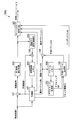
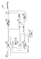
- FIG. 2 is a schematic block diagram showing the configuration of the image encoding device 100.
- the image coding apparatus 100 includes a subtracting unit 101, a DCT (Discrete Cosine Transform) transform / quantization unit 102, an entropy coding unit 103, an inverse quantization / inverse DCT transform unit 104, and an addition unit 105.
- a reference image memory 106 a prediction unit 107, a subtraction unit 108, a vector memory 109, a prediction vector generation unit 110 (prediction vector generation device), a depth map encoding unit 121, and a depth map memory 122.
- DCT Discrete Cosine Transform
- the subtraction unit 101 subtracts the predicted image P generated by the prediction unit 107 from the input viewpoint image T, and generates a residual signal indicating the subtraction result.
- the subtraction is to subtract the pixel value of the corresponding pixel of the predicted image P from the pixel value of the pixel of the viewpoint image T.
- the DCT transform / quantization unit 102 performs DCT transform on the residual signal generated by the subtraction unit 101 and calculates a DCT coefficient.
- the DCT transform / quantization unit 102 quantizes the calculated DCT coefficient to calculate a quantization coefficient.
- the entropy encoding unit 103 selects the quantization coefficient calculated by the DCT transform / quantization unit 102, the difference vector ⁇ v calculated by the subtraction unit 108, the index idx selected by the prediction vector generation unit 110, and the prediction unit 107 selects
- the prediction mode is entropy-encoded to generate an encoded stream Te.
- the inverse quantization / inverse DCT transform unit 104 inversely quantizes the quantization coefficient calculated by the DCT transform / quantization unit 102. Further, the inverse quantization / inverse DCT transform unit 104 performs inverse DCT transform on the inversely quantized result to generate a decoded residual signal.
- the adding unit 105 adds the decoded residual signal generated by the inverse quantization / inverse DCT transform unit 104 and the predicted image P generated by the prediction unit 107 to generate a decoded image.
- the reference image memory 106 stores the decoded image generated by the adding unit 105 as a reference image.
- the prediction unit 107 generates a predicted image P using a reference image stored in the reference image memory 106 for each block obtained by dividing each frame of the viewpoint image T.
- the prediction unit 107 selects one of a plurality of prediction methods, and generates a predicted image P using the selected prediction method.
- a selection method of the prediction method for example, there is a method of selecting a prediction method that minimizes the difference between the predicted image P and the viewpoint image T, but is not limited thereto, and other methods may be used.
- the prediction unit 107 notifies the prediction vector generation unit 110 of block information Ib indicating the block size of each of the blocks described above.
- the plurality of prediction methods to be selected are intra prediction and motion prediction.
- the viewpoint image T is a reference viewpoint image (also referred to as a base view)
- the plurality of selection target prediction methods are intra prediction, motion prediction, and parallax prediction.
- intra prediction is a prediction method that uses a frame to which a target block belongs as a reference image when generating a predicted image P.
- the prediction unit 107 selects intra prediction, the prediction unit 107 notifies the entropy encoding unit 103 of the prediction mode used when generating the predicted image P.
- Motion prediction (also referred to as motion compensation) is a prediction method that uses a frame different from the frame to which the target block belongs among the viewpoint images T to which the target block belongs as the reference image when generating the predicted image P.
- the prediction unit 107 selects motion prediction, the prediction unit 107 notifies the vector memory 109 and the subtraction unit 108 of the motion vector Mv used when generating the predicted image P.
- the motion vector Mv includes information indicating a vector from the coordinates of the target block to the coordinates in the reference image of the block as the predicted image P, information indicating the frame as the reference image (for example, ref_index (reference picture number), And POC; Picture Order Count (picture display order)).
- the display order is the same as the frame to which the target block belongs among the frames of the viewpoint image T different from the viewpoint image T to which the target block belongs. This is a prediction method using a frame (having the same POC).
- the prediction unit 107 selects the parallax prediction, notifies the vector memory 109 and the subtraction unit 108 of the parallax vector Dv used when generating the predicted image P.
- the disparity vector Dv includes information representing a vector from the coordinates of the target block to the coordinates in the reference image of the block as the predicted image P, information indicating the frame as the reference image (for example, ref_index (reference picture number), And view_id (view identifier)).
- the reference viewpoint image is a viewpoint image T that cannot use parallax prediction when encoding
- the non-reference viewpoint image is a viewpoint image T that can use parallax prediction when encoding.
- the image encoding device 100 sets a viewpoint image T that is first input to the image encoding device 100 among the plurality of viewpoint images T as a reference viewpoint image, and other viewpoint images T as non-reference viewpoint images. To do.
- a reference image is used.
- the subtraction unit 108 subtracts the prediction vector Pv generated by the prediction vector generation unit 110 from the motion vector Mv or the disparity vector Dv notified from the prediction unit 107, and the difference vector ⁇ v that is the subtraction result to the entropy encoding unit 103. Notice.
- the subtraction unit 108 includes information indicating a frame as a reference image included in the motion vector Mv or the disparity vector Dv in the difference vector ⁇ v.
- the vector memory 109 stores the motion vector Mv and the disparity vector Dv notified from the prediction unit 107.
- the prediction vector generation unit 110 generates a motion vector prediction vector Pv for the block in which the prediction unit 107 selects motion prediction and generates a prediction image.
- the prediction vector generation unit 110 sets a selected vector from among a plurality of candidate vectors as the prediction vector Pv, and notifies the entropy encoding unit 103 of an index idx indicating the selected candidate vector.
- a known generation method can be used for generating the motion vector prediction vector Pv.
- generation part 110 produces
- the prediction vector generation unit 110 sets a selected vector from among a plurality of candidate vectors as the prediction vector Pv, and notifies the entropy encoding unit 103 of an index idx indicating the selected candidate vector. Details of the method of generating the prediction vector Pv of the disparity vector and the index idx will be described later.
- the depth map encoding unit 121 encodes the depth map D corresponding to each frame of the viewpoint image T to generate a depth map encoded stream De.
- the depth map encoding unit 121 also generates a decoded depth map Dd obtained by decoding the depth map encoded stream De when generating the depth map encoded stream De.
- the depth map memory 122 stores the decoded depth map Dd generated by the depth map encoding unit 121.
- the depth map D and the decoded depth map Dd may be the same size (number of pixels) as the viewpoint image, or may be a size reduced to 1/2, 1/4, 1/8, etc. from the size of the viewpoint image. Good.
- FIG. 3 is a schematic block diagram showing the configuration of the prediction vector generation unit 110.
- the prediction vector generation unit 110 includes a first candidate vector generation unit 111, a second candidate vector generation unit 114, a prediction vector determination unit 115, a motion vector prediction unit 116, and a switch unit 117.
- the first candidate vector generation unit 111 includes a conversion pixel determination unit 112 and a disparity vector conversion unit 113.
- the transformed pixel determination unit 112 selects a rule for determining a pixel position in a block (hereinafter referred to as a depth block) in the decoded depth map Dd corresponding to the target block,
- the pixel position determined according to the selected determination rule is input to the parallax vector conversion unit 113.
- the block information Ib includes the block size (width, height) and the upper left coordinates of the block.
- the block size is the size of a prediction block (PU, prediction unit).
- the upper left coordinates of the block (x, y) and the block size are nPW and nPH
- the depth block The coordinates (x0, y0) and the sizes w and h can be derived from the following equations.
- the transformed pixel determination unit 112 selects a rule for determining a pixel position in a block (hereinafter referred to as a depth block) in the decoded depth map Dd corresponding to the target block,
- the pixel position determined according to the selected determination rule is input to the parallax vector conversion unit 113. More specifically, the determination rule is selected such that the larger the block size indicated by the block information Ib, the smaller the ratio of the number of determined pixel positions to the number of pixels of the depth block.
- the disparity vector conversion unit 113 sets the depth value at the pixel position determined by the conversion pixel determination unit 112 as a depth value when converting the decoded depth map Dd into a disparity vector.
- the conversion pixel determination unit 112 determines the determination rule depending on whether or not the block size indicated by the block information Ib is larger than a preset threshold of the block size (number of pixels). Select.
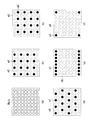
- the decision rule when it is large is that it is an even number in the depth block in both the vertical and horizontal directions, and the decision rule when it is not large is that all the pixel positions (or one point) in the depth block are used. is there.
- the pixel position at the upper left corner of the depth block is 0th in both the vertical and horizontal directions.
- the size of the prediction target block is 32 pixels ⁇ 32 pixels
- the corresponding block Dblk (hereinafter referred to as a depth block) in the depth map is 8 pixels ⁇ 8 pixels as shown in FIG.
- a preset block size threshold for example, 16 ⁇ 16
- the pixel position to be converted into a disparity vector is determined.
- a predetermined point is determined as a pixel position to be converted into a disparity vector.
- the predetermined one point is the upper left coordinate.
- the conversion pixel determination unit 112 notifies the determined pixel position to the parallax vector conversion unit 113.
- the disparity vector conversion unit 113 calculates the average value Dave of the depth values of the pixel positions input from the conversion pixel determination unit 112, and converts the average value Dave into a disparity vector.
- the disparity vector conversion unit 113 inputs the converted disparity vector to the prediction vector determination unit 115.
- the converted pixel determining unit 112 is configured as in the above example, when the block size of the target block is larger than the threshold, the converted pixel determining unit 112 inputs only the pixel position of the pixel p1 to the disparity vector converting unit 113. To do. For this reason, the disparity vector conversion unit 113 does not use the depth value of the pixel p0 that is a pixel at a pixel position that is not input for disparity vector conversion. Thereby, the amount of calculation processing in parallax vector conversion can be reduced.
- the parallax vector conversion unit 113 has been described as converting the average value Dave of depth values into a parallax vector, the median value, the mode value, the minimum value, the maximum value, and the like may be converted into a parallax vector.
- the order of calculation processing amount when calculating, such as the median is larger than O (n) when the number of data is n (for example, O (n 2 ) or O (nlogn))
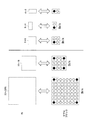
- FIG. 4B is an example in which the number of pixels in each of the horizontal direction and the vertical direction in the block is used to determine only the even-numbered pixel positions.
- the decision rule at 112 is not limited to this.
- a decision rule for only the odd-numbered pixel positions in the horizontal and vertical directions and as shown in FIG. 4 (d), even-numbered positions and odd-numbered positions are alternately set for each pixel row.
- Decision rule to be selected and used decision rule for only the top and bottom row pixels in the block as shown in FIG. 4E, and pixels at the four corners in the block as shown in FIG. It may be a decision rule that targets only.
- 4B to 4D are examples in which the number of pixels is 1 ⁇ 2 of the original depth block in each of the horizontal direction and the vertical direction.
- the number of pixels such as 8 may be targeted. At that time, target pixels may be selected so that the number of pixels is different from each other in the horizontal direction and the vertical direction.
- the conversion pixel determination unit 112 can select a target pixel by a fixed process regardless of the block size. In this case, loop processing that is determined depending on the block size is not necessary, so processing such as loop variable initialization, loop end determination, and loop variable update is unnecessary, which reduces the amount of processing. Is possible.
- the loop overhead is larger than the number of target points.
- Dmax depth [x0] [y0] if (Dmax> depth [x0 + w-1] [y0] + depth)
- Dmax depth [x0 + w-1] [y0] if (Dmax> depth [x0] [y0 + h-1] + depth)
- Dmax depth [x0 + w-1] [y0 + h-1] if (Dmax> depth [x0 + w-1] [y0 + h-1] + depth)
- Dmax depth [x0 + w-1] [y0 + h-1] [y0 + h-1]
- the conversion pixel determination unit 112 determines the target pixel based on the block information Ib.
- the target for conversion from a depth block to a disparity vector is not dependent on the block information Ib. Pixels may be determined as described above. In other words, regardless of the size of the target block, the number of pixels in each half of the depth block in the horizontal direction and the vertical direction may always be selected and converted into a disparity vector.
- the depth block selects an even pixel position or an odd pixel position in each of the horizontal direction and the vertical direction, or combine the number of pixels to 1/4 or 1/8 instead of 1/2.
- the original size of the depth block is less than the number of pixels to be selected, such as 1 pixel ⁇ 2 pixels or 2 pixels ⁇ 2 pixels, that is, 1/2, 1/4, 1/8, etc. If the number of pixels is less than one pixel, the pixel at a specific position (for example, the upper left position) of the depth block is selected as a target.
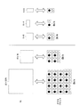
- the number of pixels in each of the horizontal direction and the vertical direction in the block is 1 ⁇ 2 as shown in FIG. FIG. 5 shows a case where the blocks are 32 ⁇ 32, 16 ⁇ 16, 8 ⁇ 8, 8 ⁇ 4, and 4 ⁇ 8.
- the corresponding depth blocks are 8x8, 4x4, 2x2, 2x1, and 1x2, respectively.
- a selected pixel is determined by vertical and horizontal sub-sampling.
- depth [x] [y] is the depth value at coordinates (x, y)
- x0, y0 are the upper left coordinates of the block
- w is the width of the block
- h is the height of the block.
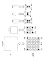
- the pixels at the four corners in the block are used as shown in FIG.
- FIG. 6 shows a case where four corners are used when the depth map has a size that is a quarter of the vertical and horizontal directions of the parallax image.
- the conversion pixel determination unit 112 refers to the four points p1a, p1b, p1c, and p1d.
- the conversion pixel determination unit 112 may be configured to select 4 points regardless of the block size, or select 4 points, 2 points, 1 point, etc. according to the block size, excluding points with the same coordinates. The structure to do may be sufficient.
- the parallax vector conversion unit 113 calculates the average value or the maximum value from the depth value of the selected pixel, the result is the same regardless of whether the calculation is performed using four points or two points. In this configuration, since four fixed points are used without depending on the block size, processing related to loop processing can be omitted, and processing speed and ease of mounting can be improved.
- the block information Ib includes Even if it is not dependent, it is possible to reduce the amount of calculation processing in disparity vector conversion when the block size of the target block is large.
- a determination rule different from the above can also be used. More specifically, when the block size indicated by the block information Ib is greater than or equal to the predetermined size, the predetermined sampling rule is set as the determination rule, and when the block size is less than the predetermined size, the pixel position to be determined is determined. The decision rule is selected so that the number is 1. In this case, if the block size is equal to or smaller than the predetermined size, only one point is used, so that the processing amount is reduced especially when the block size requiring a small latency is small as in the case where the block size is large. Can do.
- FIG. 7 shows an example of a configuration in which four corners are used when the block size is larger than a predetermined block size, and one point is used in other cases. That is, one point is used when the maximum width and height of the block size is 8 or less, and four corners are used otherwise.
- a fixed point is used regardless of the block size, loop processing can be omitted.
- the score in the small-sized block is one point, the processing speed in the small size can be further improved.
- the second candidate vector generation unit 114 reads, from the vector memory 109, the disparity vector Dv that the adjacent block of the target block has.
- the second candidate vector generation unit 114 notifies the prediction vector determination unit 115 of the read disparity vector Dv as the second candidate vector.
- disparity vectors are read for one of the blocks adjacent on the left side and one of the blocks adjacent on the upper side, and a maximum of two second candidate vectors are generated. If there is no disparity vector in an adjacent block, a candidate vector for that adjacent block is not generated.
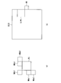
- FIG. 8A shows the relationship between the target block and adjacent blocks.
- the adjacent blocks from which the disparity vector is read for the target block PU are the blocks NBa0, NBa1, NBb0, NBb1, and NBb2 in the figure.
- the parallax vectors of each block are referred to in the order of the blocks NBa0 and NBa1 adjacent to the left side of the target block, and set as one candidate vector.
- the disparity vectors of the respective blocks are referred to in the order of the blocks NBb0, NBb1, and NBb2 adjacent to the upper side of the target block, and set as one candidate vector.
- the maximum number of second candidate vectors is two, but other numbers may be used.
- the prediction vector determination unit 115 selects a vector having a small difference from the parallax vector of the target block from the first candidate vector and the second candidate vector, and sets it as the prediction vector Pv.
- the prediction vector determination unit 115 generates an index idx indicating which one of the first candidate vector and the second candidate vector is the prediction vector. Note that the first candidate vector generation unit 111, the second candidate vector generation unit 114, and the prediction vector determination unit 115 operate only when a predicted image of the target block is generated by parallax prediction.
- the motion vector prediction unit 116 generates a motion vector prediction vector and an index idx.
- a method for generating a prediction vector by the motion vector prediction unit 116 a known method can be used.
- the motion vector prediction unit 116 reads motion vectors of a plurality of blocks adjacent to the target block from the vector memory 109, and sequentially sets the read motion vectors as candidate vectors according to the positions of the adjacent blocks.
- the motion vector prediction unit 116 selects a vector having a small difference from the motion vector of the target block from among a plurality of candidate vectors, and sets it as the prediction vector Pv.
- the motion vector prediction unit 116 generates an index idx indicating which vector is the prediction vector among the plurality of candidates. Note that the motion vector prediction unit 116 operates only when a predicted image of the target block is generated by motion prediction.
- the switch unit 117 When the prediction vector Pv and the index idx are input from the prediction vector determination unit 115 or the motion vector prediction unit 116, the switch unit 117 notifies the input prediction vector Pv and the index idx to the entropy encoding unit 103. To do.
- FIG. 9 is a schematic block diagram illustrating a configuration of another image encoding device 100a according to the present embodiment.
- a difference from the image encoding device 100 is that a depth map generating unit 123 is provided instead of the depth map encoding unit 121 and the depth map memory 122.
- the depth map generation unit 123 reads the disparity vector from the vector memory 109 and generates a pseudo depth map.
- the depth value constituting the depth map is generated by performing the inverse conversion of the process for converting the depth map into the disparity vector as described above.
- the size (number of pixels) of the depth map to be generated is determined according to the number of obtained disparity vectors, but the missing pixels are copied from adjacent pixels or interpolated using a plurality of neighboring pixels, You may make it the same as the size of a viewpoint image. Alternatively, a depth map having a size such as 1/2, 1/4, or 1/8 of the size of the viewpoint image may be generated.
- the depth map generation unit 123 also generates the depth value of the target block by copying from adjacent pixels or by interpolating using a plurality of neighboring pixels.
- the other units included in the image encoding device 100a are the same as those of the image encoding device 100.
- a disparity prediction vector is generated using the prediction vector generation unit 110 in the same manner as the image encoding device 100 by generating a pseudo depth map. Can do.
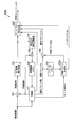
- FIG. 10 is a schematic block diagram showing the configuration of the image decoding device 300.
- the image decoding device 300 includes an entropy decoding unit 301, an inverse quantization / inverse DCT conversion unit 302, an addition unit 303, an addition unit 304, a vector memory 305, a prediction vector generation unit 306 (a prediction vector generation device). ), A prediction unit 307, a reference image memory 308, a depth map decoding unit 309, and a depth map memory 310.
- the entropy decoding unit 301 performs a decoding process corresponding to the encoding scheme in the entropy encoding unit 103 in FIG. 2 on the encoded stream Te.
- the entropy decoding unit 301 separates the index idx, the difference vector ⁇ v, the quantization coefficient, and the prediction mode from the result of this decoding process.
- the inverse quantization / inverse DCT transform unit 302 performs the same process as the inverse quantization / inverse DCT transform unit 104 in FIG. 2 on the quantized coefficients separated by the entropy decoding unit 301 to generate a decoded residual signal.
- the addition unit 303 adds the decoded residual signal generated by the inverse quantization / inverse DCT conversion unit 302 and the predicted image P generated by the prediction unit 307, thereby generating a decoded viewpoint image Td.
- the addition unit 304 adds the difference vector ⁇ v separated by the entropy decoding unit 301 and the prediction vector Pv generated by the prediction vector generation unit 306 to generate a motion vector Mv or a disparity vector Dv.
- the adding unit 304 stores the generated motion vector Mv and the disparity vector Dv in the vector memory 305.
- the vector memory 305 stores a motion vector Mv and a disparity vector Dv.
- the prediction vector generation unit 306 generates the prediction vector Pv by referring to the index idx separated by the entropy decoding unit 301, the vector stored in the vector memory 305, and the decoded depth map Dd stored in the depth map memory 310. . Details of the prediction vector generation unit 306 will be described later.
- the prediction unit 307 generates a predicted image P of each block obtained by dividing the viewpoint image T.
- the prediction unit 307 generates the prediction image P of each block using the same prediction method as that used in the prediction unit 107 in FIG. Note that the reference image for generating the predicted image P is acquired from the reference image memory 308. Also, the prediction unit 307 inputs block information Ib indicating the block size of each block to the prediction vector generation unit 306. For the block in which the prediction image P is generated by the intra prediction in the prediction unit 107, the prediction unit 307 performs intra prediction according to the prediction mode separated by the entropy decoding unit 301, and generates the prediction image P.
- the prediction unit 307 For the block in which the prediction image P is generated by the motion prediction in the prediction unit 107, the prediction unit 307 performs motion prediction using the motion vector Mv of the block stored in the vector memory 305, and the prediction image P Is generated. For the block for which the prediction image P is generated by the parallax prediction in the prediction unit 107, the prediction unit 307 performs the parallax prediction using the parallax vector Dv of the block stored in the vector memory 305, and the prediction image P Is generated.
- the reference image memory 308 stores the decoded viewpoint image Td generated by the addition unit 303 as a reference image.
- the depth map decoding unit 309 performs a decoding process corresponding to the encoding scheme in the depth map encoding unit 121 of FIG. 2 on the depth map encoded stream De, and generates a decoded depth map Dd.
- the depth map memory 310 stores the decoded depth map Dd generated by the depth map decoding unit 309.
- FIG. 11 is a schematic block diagram showing the configuration of the prediction vector generation unit 306.
- the prediction vector generation unit 306 includes a first candidate vector generation unit 111, a second candidate vector generation unit 114, a prediction vector selection unit 361, a motion vector prediction unit 362, and a switch unit 363.
- the same reference numerals (111 to 114) are assigned to portions corresponding to the respective portions of the prediction vector generation unit 110 shown in FIG. 3, and the description thereof is omitted.
- the predicted vector selection unit 361 selects the vector indicated by the index idx from the candidate vectors generated by the first candidate vector generation unit 111 and the candidate vectors generated by the second candidate vector generation unit 114.
- the motion vector prediction unit 362 generates a candidate vector in the same manner as the motion vector prediction unit 116 in FIG. 3, and selects a vector indicated by the index idx from these.
- the switch unit 363 outputs the vector selected by the prediction vector selection unit 361 as the prediction vector Pv when the prediction method is a block of parallax prediction. In addition, when the prediction method is a motion prediction block, the switch unit 363 outputs the vector selected by the motion vector prediction unit 362 as a prediction vector Pv.
- FIG. 12 is a schematic block diagram illustrating a configuration of another image decoding device 300a according to the present embodiment.
- a difference from the image decoding apparatus 300 is that a depth map generation unit 311 is provided instead of the depth map decoding unit 309 and the depth map memory 310.
- the depth map generation unit 311 reads a disparity vector from the vector memory 305 and generates a pseudo depth map in the same manner as the depth map generation unit 123 in the image encoding device 100a.
- the depth value constituting the depth map is generated by performing the inverse conversion of the process for converting the depth map into the disparity vector as described above.
- the size (number of pixels) of the depth map to be generated is determined according to the number of obtained disparity vectors, but the missing pixels are copied from adjacent pixels or interpolated using a plurality of neighboring pixels, You may make it the same as the size of a viewpoint image. Alternatively, a depth map having a size such as 1/2, 1/4, or 1/8 of the size of the viewpoint image may be generated.
- the depth map generation unit 311 also generates the depth value of the target block by copying from adjacent pixels or by interpolating using a plurality of neighboring pixels.
- the other units included in the image decoding device 300a are the same as those of the image decoding device 300. With this configuration, even when a depth map is not given from the outside, it is possible to generate a parallax prediction vector using the prediction vector generation unit 306 in the same manner as the image decoding device 300 by generating a pseudo depth map. it can. As described above, in this embodiment, by generating a disparity vector using a part of pixels in the depth map, a disparity prediction vector is efficiently generated while suppressing an increase in the amount of calculation in the encoding / decoding process. can do.
- a prediction vector of a disparity vector is generated using a depth map input from the outside of the apparatus or a depth map generated from a viewpoint image.
- a depth map is not required, and a prediction vector of a disparity vector is generated using information on a block spatially and temporally adjacent to the target block.
- the image transmission system 10a in this embodiment includes an image encoding device 100a instead of the image encoding device 100, and an image decoding device 300a instead of the image decoding device 300.
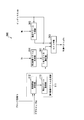
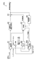
- FIG. 13 is a schematic block diagram illustrating a configuration of the image encoding device 100b. In the figure, parts corresponding to the respective parts of the image coding apparatus 100 shown in FIG. 2 are denoted by the same reference numerals (101 to 109, 111, 112), and description thereof is omitted. As illustrated in FIG.
- the image encoding device 100 b includes a subtraction unit 101, a DCT transform / quantization unit 102, an entropy encoding unit 103, an inverse quantization / inverse DCT transform unit 104, an addition unit 105, and a reference image memory 106.
- FIG. 14 is a schematic block diagram illustrating a configuration of the prediction vector generation unit 110a.
- the prediction vector generation unit 110a includes a first candidate vector generation unit 111a, a second candidate vector generation unit 114, a prediction vector determination unit 115, a motion vector prediction unit 116, and a switch unit 117.
- the first candidate vector generation unit 111a includes a motion vector acquisition unit 118 and a disparity vector acquisition unit 119.
- the description of the parts denoted by the same reference numerals (114 to 117) in FIG. 3 is omitted.
- the motion vector acquisition unit 118 acquires a motion vector Mv of a block at another viewpoint corresponding to the target block.
- FIG. 8B shows a block corresponding to the target block.
- the motion vector acquisition unit 118 is a block included in an image of a different viewpoint from the viewpoint image including the target block (a reference picture having the same display order in time as the picture including the target block), and is located at the same position as the target block.
- a certain block CLPU a coding unit block CLCU including CLPU, and an adjacent block BB adjacent to the lower right of the CLPU
- the availability of the motion vector is checked, and the motion vector is acquired when it is available.
- the motion vectors are acquired in the above-described order, and the acquisition of the vectors is terminated when the motion vectors can be acquired (the first block having a referenceable motion vector).
- the coding unit block is a block obtained by dividing each frame into equal sizes, such as LCU (Largest Coding Unit) in HEVC (High Efficiency Video Coding).
- the block for generating the prediction image is the same as the coding unit block or a block obtained by further dividing the coding unit block.
- the motion vector related to the coding unit block CLCU is any motion vector of each block (block that generates a prediction image) obtained by dividing the coding unit block CLCU. That is, if any of the blocks obtained by dividing the coding unit block CLCU has a motion vector, it is acquired as a motion vector related to the coding unit block CLCU.
- the adjacent block BB is also a block in the coding unit block CLCU.
- the adjacent block BB has a motion vector, it is acquired as a motion vector related to the coding unit block CLCU. Is done.
- the adjacent block BB is located outside the coding unit block CLCU. Even if the motion vector related to the quantization unit block CLCU is not acquired, the motion vector of the adjacent block BB may be acquired.
- the motion vector and the disparity vector of a certain block X are referred to as follows.
- the prediction mode predMode of the block X or the two prediction flags predFlagL0 and predFlagL1 of the block X it is checked whether or not the block X is inter-predicted. If the prediction mode predMode is MODE_INTRA, intra prediction is used. Otherwise, inter prediction is used.
- the prediction flags predFlagL0 and predFlagL1 indicate whether or not reference pictures belonging to the reference list L0 and the reference list L1 are used for prediction image generation. If the prediction flags predFlagL0 and predFlagL1 are both 1, bi-prediction of inter prediction, if only one of them is 1, inter-prediction single prediction, and if both are 0, intra-prediction. If block X is not inter predicted, the motion vector and disparity vector of block X are not available. When the prediction flag predFlagLX of the reference list LX is 1, the reference picture used for prediction image generation is specified by the reference picture index refIdxLX.
- RefPicListX is an array for referring to the reference picture from the reference picture index redIdxLX
- PicOrderCnt (x) is a function for obtaining the display order of the reference picture specified by the argument x.
- the reference picture index refIdxL0 for the L0 list of the target block the reference picture index refIdxL0 for the L0 list of the block X and the vector for the reference list L0 are referred to, but the reference for the reference list L1 of the block X You may refer to the picture index ref_L1idx and the vector for the reference list L0. The same applies to the reference picture index refIdxL1 for the reference list L1 of the target block.
- the vector of the block X held in the vector memory is a motion vector
- the motion vector can be used, and the motion vector mvLX is derived.
- the vector of the block X held in the vector memory is a disparity vector
- the disparity vector can be used, and the disparity vector mvLX is derived.
- the disparity vector acquisition unit 119 acquires a disparity vector Dv of a block adjacent to the target block.
- the disparity vector obtaining unit 119 includes an adjacent disparity vector deriving unit, a temporal disparity vector deriving unit, and a fixed disparity vector deriving unit (not shown).
- the disparity vector acquisition unit 119 acquires disparity vectors in the order of the adjacent disparity vector and the temporal disparity vector as will be described later, and outputs the disparity vector as the first candidate vector when any disparity vector is obtained. To do. If no disparity vector is obtained, a zero vector is output as the first candidate vector.
- FIG. 8A shows the relationship between the target block and its adjacent blocks.
- the adjacent blocks from which the disparity vector is read for the target block PU are the blocks NBa0, NBa1, NBb0, NBb1, and NBb2 in the figure.
- the disparity vector acquisition unit 119 refers to the availability of disparity vectors of each block in the order of the blocks NBa0 and NBa1 adjacent to the left side of the target block in the adjacent disparity vector acquisition unit, and when there is an available disparity vector Uses the disparity vector of the block referred to first as the first candidate vector.
- the adjacent disparity vector acquisition unit When there is no available disparity vector in any of the blocks adjacent to the left, the adjacent disparity vector acquisition unit further disparity vectors of each block in the order of the blocks NBb0, NBb1, and NBb2 adjacent to the upper side of the target block When there is a disparity vector that can be used, the disparity vector of the block that is referred to first is set as the first candidate vector.
- the temporal disparity vector acquisition unit included in the disparity vector acquisition unit 119 is a reference picture in a display order different in time, to which the motion vector acquired by the motion vector acquisition unit 118 points.
- the disparity vector of the block included in is acquired.
- the disparity vector acquisition unit 119 sets the first candidate vector as a zero vector in the fixed disparity vector acquisition unit.
- the motion vector acquisition unit 118 and the disparity vector acquisition unit 119 switch processing with reference to the block information Ib. For example, when the block size of the target block included in the block information Ib is smaller than a predetermined size (for example, 16 ⁇ 16), the disparity vector acquisition unit 119 does not acquire a disparity vector referring to a motion vector. Only the disparity vector or the fixed vector related to the block adjacent to the target block is acquired. In addition, the motion vector acquisition unit 118 does not acquire a motion vector used for acquiring a disparity vector.
- a predetermined size for example, 16 ⁇ 16
- the disparity vector acquisition unit 119 acquires disparity vectors in the order of the adjacent disparity vector acquisition unit, the temporal disparity vector acquisition unit, and the fixed disparity vector acquisition unit.
- the disparity vector acquisition unit 119 performs processing excluding the temporal disparity vector acquisition unit, that is, acquisition of disparity vectors in the order of the adjacent disparity vector acquisition unit and the fixed disparity vector acquisition unit.
- the block size may be determined by using the PU size that is the size of the prediction block (PU) or the size of the CU that has a structure including the PU. Further, a CU size and a PU partition type having a meaning equivalent to the PU size may be used.
- the processing is switched based on the block information Ib.
- the processing is switched based on the encoding condition. May be.
- the disparity vector acquisition unit 119 uses only the information on adjacent blocks to operate the disparity vector without operating the motion vector acquisition unit 118.
- the motion vector acquisition unit 118 and the disparity vector acquisition unit 119 are always operated to refer to the disparity vectors and motion vectors of adjacent blocks. Thus, a disparity vector may be acquired.
- FIG. 15 is a schematic block diagram illustrating a configuration of the image decoding device 300b.
- the same reference numerals (301 to 305, 307 to 308) are assigned to portions corresponding to the respective portions in FIG. 10, and description thereof is omitted.
- the image decoding device 300b includes an entropy decoding unit 301, an inverse quantization / inverse DCT conversion unit 302, an addition unit 303, an addition unit 304, a vector memory 305, a prediction vector generation unit 306a, a prediction unit 307, A reference image memory 308 is included.
- FIG. 16 is a schematic block diagram illustrating a configuration of the prediction vector generation unit 306a.
- the prediction vector generation unit 306a includes a first candidate vector generation unit 111a, a second candidate vector generation unit 114, a prediction vector selection unit 361, a motion vector prediction unit 362, and a switch unit 363.
- the first candidate vector generation unit 111a includes a motion vector acquisition unit 118 and a disparity vector acquisition unit 119.
- each component is the same as that contained in FIG. 11 or FIG. 14, and description is abbreviate
- the image encoding device 100, the image decoding device 300, the image encoding devices 100a and 100b, the functions of the image decoding devices 300a and 300b, or a program for realizing a part of these functions can be read by a computer.
- Each apparatus may be realized by recording on a medium, causing the computer system to read and execute a program recorded on the recording medium.
- the “computer system” includes an OS and hardware such as peripheral devices.
- the “computer-readable recording medium” means a storage device such as a flexible disk, a magneto-optical disk, a portable medium such as a ROM and a CD-ROM, and a hard disk incorporated in a computer system. Furthermore, the “computer-readable recording medium” dynamically holds a program for a short time like a communication line when transmitting a program via a network such as the Internet or a communication line such as a telephone line. In this case, a volatile memory in a computer system serving as a server or a client in that case, and a program that holds a program for a certain period of time are also included.
- the program may be a program for realizing a part of the functions described above, and may be a program capable of realizing the functions described above in combination with a program already recorded in a computer system.
- part or all of the image encoding device 100, the image decoding device 300, the image encoding devices 100a and 100b, and the image decoding devices 300a and 300b may be realized as an LSI that is typically an integrated circuit. .
- Each functional block of each device may be individually made into a processor, or part or all may be integrated into a processor.
- the method of circuit integration is not limited to LSI, and may be realized by a dedicated circuit or a general-purpose processor.
- an integrated circuit based on the technology can also be used.
- DESCRIPTION OF SYMBOLS 10 ... Image transmission system 100, 100a, 100b ... Image coding apparatus 101 ... Subtraction part 102 ... DCT transformation / quantization part 103 ... Entropy coding part 104 ... Inverse quantization / inverse DCT transformation part 105 ... Addition part 106 ... reference Image memory 107 ... Prediction unit 108 ... Subtraction unit 109 ... Vector memory 110, 110a ... Prediction vector generation unit 111, 111b ... First candidate vector generation unit 112 ... Conversion pixel determination unit 113 ... Disparity vector conversion unit 114 ... Second candidate vector Generation unit 115: Prediction vector determination unit 116 ... Motion vector prediction unit 117 ... Switch unit 118 ...
- Motion vector acquisition unit 119 Disparity vector acquisition unit 121 ... Depth map encoding unit 122 ... Depth map memory 123 ... Depth map generation unit 200 ... Network 300, 300a ... Image Decoding device 301 ... Entropy decoding unit 302 ... Inverse quantization / inverse DCT conversion unit 303 ... Addition unit 304 ... Addition unit 305 ... Vector memory 306, 306a ... Prediction vector generation unit 307 ... Prediction unit 308 ... Reference image memory 309 ... Depth map Decoding section 310 ... Depth map memory 311 ... Depth map generation section 361 ... Prediction vector selection section 362 ... Motion vector prediction section 363 ... Switch section 400 ... Free viewpoint image display device
Abstract
Description
また、ISO(International Organization For Standardization)では、3次元映像符号の標準規格であり、複数の視点画像とデプスマップとを符号化するMPEG-3DVの規格化が行われている(非特許文献3)。 In the encoding of a moving image, motion prediction is performed by dividing a frame into blocks and acquiring an image close to the block from another frame as a predicted image. A vector indicating an image close to the block is called a motion vector, and the motion vector of the block is predicted from the motion vectors of the blocks around the block (for example, Non-Patent
In addition, ISO (International Organization For Standardization) is a standard for 3D video codes, and standardization of MPEG-3DV that encodes a plurality of viewpoint images and depth maps is performed (Non-patent Document 3). .
(10)また、本発明の他の態様は、コンピュータを、非基準視点画像における対象ブロックの視差ベクトルの予測ベクトルを生成する予測ベクトル生成装置として機能させるために、前記非基準視点画像とは別の視点画像において前記対象ブロックに対応するブロックに関する動きベクトルを取得する動きベクトル取得部、前記取得した動きベクトルを参照して、前記非基準視点画像の他の時刻の視点画像におけるブロックを選択し、該ブロックに関する視差ベクトルを取得する第1の取得方法、もしくは、前記対象ブロックの隣接ブロックに関する視差ベクトルを取得する第2の取得方法を用いて視差ベクトルを取得する視差ベクトル取得部、前記視差ベクトル取得部が取得した視差ベクトルを用いて、前記対象ブロックの視差ベクトルの予測ベクトルを決定する予測ベクトル決定部として機能させるためのプログラムである。 (9) Further, another aspect of the present invention corresponds to the non-reference viewpoint image in order to cause a computer to function as a prediction vector generation device that generates a prediction vector of a disparity vector of a target block in a non-reference viewpoint image. In the depth map, a converted pixel determining unit that determines one or more pixel positions in the depth block corresponding to the target block, a representative value of the depth value of the pixel position determined by the converted pixel determining unit is calculated, and the representative value Is a program for functioning as a prediction vector determination unit that generates a prediction vector of a disparity vector of the target block using a disparity vector conversion unit that converts a parallax vector into a disparity vector, and a disparity vector generated by the disparity vector conversion unit.
(10) According to another aspect of the present invention, in order to cause a computer to function as a prediction vector generation device that generates a prediction vector of a disparity vector of a target block in a non-reference viewpoint image, the computer is different from the non-reference viewpoint image. A motion vector acquisition unit that acquires a motion vector related to the block corresponding to the target block in the viewpoint image, and refers to the acquired motion vector, and selects a block in the viewpoint image at another time of the non-reference viewpoint image, A disparity vector acquisition unit that acquires a disparity vector using a first acquisition method for acquiring a disparity vector related to the block or a second acquisition method that acquires a disparity vector related to an adjacent block of the target block, and the disparity vector acquisition The disparity vector of the target block using the disparity vector acquired by the unit Is a program for functioning as a predictive vector determination unit for determining a prediction vector.
以下、図面を参照して、本発明の第1の実施形態について説明する。図1は、この発明の第1の実施形態による画像伝送システム10の構成を示す概略ブロック図である。画像伝送システム10は、複数の視点画像とデプスマップとを符号化して伝送し、伝送先において、これらを用いた自由視点画像の表示を可能とするシステムである。図1に示すように、画像伝送システム10は、画像符号化装置100、ネットワーク200、画像復号装置300、自由視点画像表示装置400を含んで構成される。 [First Embodiment]
Hereinafter, a first embodiment of the present invention will be described with reference to the drawings. FIG. 1 is a schematic block diagram showing the configuration of an
なお、デプスマップDおよび復号デプスマップDdは、視点画像と同じサイズ(画素数)でもよいし、視点画像のサイズから1/2、1/4、1/8等に縮小したサイズであってもよい。 The depth
The depth map D and the decoded depth map Dd may be the same size (number of pixels) as the viewpoint image, or may be a size reduced to 1/2, 1/4, 1/8, etc. from the size of the viewpoint image. Good.
x0 = x >> dn
y0 = x >> dn
w = nPW>>dn
h = nPH>>dn ここで>>は右シフトを示す。 If the depth map is reduced to 1 / DN of the viewpoint image (DN = 2 ^ dn times), if the upper left coordinates of the block (x, y) and the block size are nPW and nPH, the depth block The coordinates (x0, y0) and the sizes w and h can be derived from the following equations.
x0 = x >> dn
y0 = x >> dn
w = nPW >> dn
h = nPH >> dn where >> indicates a right shift.
変換画素決定部112は、予測部107から得られるブロック情報Ibに基づいて、対象ブロックに対応する、復号デプスマップDdにおけるブロック(以降、デプスブロックという)中の画素位置の決定規則を選択し、該選択した決定規則に従って決定した画素位置を視差ベクトル変換部113に入力する。より、具体的には、ブロック情報Ibが示すブロックサイズが大きいほど、デプスブロックの画素数に対する、決定される画素位置の数の比が小さくなるように、決定規則を選択する。視差ベクトル変換部113は、後述するように、変換画素決定部112が決定した画素位置のデプス値を、復号デプスマップDdから視差ベクトルに変換する際のデプス値とする。 <Configuration example using different selection rules depending on block size>
Based on the block information Ib obtained from the
具体的に、ブロック内の固定のN点(N=2^n、ここではn=2)を用いて対象画素を選択し、視差ベクトル変換部113が、選択した画素のデプス値から最大値Dmaxを算出する例を示す。 When the conversion
Specifically, the target pixel is selected using fixed N points (N = 2 ^ n, here n = 2) in the block, and the disparity
if (Dmax > depth [x0+w-1][y0] + depth) Dmax = depth [x0+w-1][y0]
if (Dmax > depth [x0][y0+h-1] + depth) Dmax = depth [x0+w-1][y0+h-1]
if (Dmax > depth [x0+w-1][y0+h-1] + depth) Dmax = depth [x0+w-1][y0+h-1]
この場合、最大値の決定に用いる分岐数が固定となるため、上述したループ不要の効果だけでなく、実装を容易にすることができる。
<ブロックサイズに依存しない選択規則を用いる構成例> Dmax = depth [x0] [y0]
if (Dmax> depth [x0 + w-1] [y0] + depth) Dmax = depth [x0 + w-1] [y0]
if (Dmax> depth [x0] [y0 + h-1] + depth) Dmax = depth [x0 + w-1] [y0 + h-1]
if (Dmax> depth [x0 + w-1] [y0 + h-1] + depth) Dmax = depth [x0 + w-1] [y0 + h-1]
In this case, since the number of branches used to determine the maximum value is fixed, not only the above-described effect of not requiring a loop but also the mounting can be facilitated.
<Example of configuration using selection rule independent of block size>
変換画素決定部112が、サンプリング間隔stで選択し、視差ベクトル変換部113が、選択した画素のデプス値から平均値Daveを算出する場合、平均値の導出は一般に、以下の式で算出される。 In one configuration example of the conversion
When the conversion
shift = log2(w*h)
for (j = y0; j < y0 + w; j+=st) {
for (i = x0; i < x0 + w; i+=st) {
sum += depth[i][j]
}
}
Dave=sum >> shift sum = 0;
shift = log2 (w * h)
for (j = y0; j <y0 + w; j + = st) {
for (i = x0; i <x0 + w; i + = st) {
sum + = depth [i] [j]
}
}
Dave = sum >> shift
変換画素決定部112の用いる決定規則としては、上記とは別の決定規則を用いることもできる。より、具体的には、ブロック情報Ibが示すブロックサイズが所定のサイズより以上である場合には、所定のサンプリング規則を決定規則とし、所定のサイズ未満である場合に、決定される画素位置の数が1となるように、決定規則を選択する。この場合、ブロックサイズが所定のサイズ以下の場合は、1点のみを用いるため、ブロックサイズが大きい場合と同様に、特に小レイテンシを必要とされるブロックサイズが小さい場合の処理量も削減することができる。 <Configuration example using another decision rule depending on block size>
As a determination rule used by the conversion
この場合には、ブロックサイズによらず固定的な点を用いるため、ループ処理を省くことができる。また、小サイズのブロックにおける点数を1点とするため、小サイズにおける処理速度をさらに向上させることができる。 In another configuration example of the conversion
In this case, since a fixed point is used regardless of the block size, loop processing can be omitted. In addition, since the score in the small-sized block is one point, the processing speed in the small size can be further improved.
次に、復号装置の別の構成例について説明する。図12は、本実施形態における別の画像復号装置300aの構成を示す概略ブロック図である。画像復号装置300との違いは、デプスマップ復号部309、デプスマップメモリ310の代わりに、デプスマップ生成部311を備えることである。 (Another configuration of the decoding device)
Next, another configuration example of the decoding device will be described. FIG. 12 is a schematic block diagram illustrating a configuration of another
このように、本実施形態では、デプスマップ内の一部の画素を利用して視差ベクトルを生成することにより、符号化/復号処理における演算量の増加を抑えながら、効率よく視差予測ベクトルを生成することができる。 The other units included in the
As described above, in this embodiment, by generating a disparity vector using a part of pixels in the depth map, a disparity prediction vector is efficiently generated while suppressing an increase in the amount of calculation in the encoding / decoding process. can do.
以下、図面を参照して、本発明の第2の実施形態について説明する。第1の実施形態では、視差ベクトルの予測ベクトルを生成する際に、装置外部から入力されたデプスマップもしくは視点画像から生成したデプスマップを利用して、視差ベクトルの予測ベクトルを生成していた。第2の実施形態では、デプスマップを必要とせず、対象ブロックに空間的時間的に隣接するブロックの情報を利用して視差ベクトルの予測ベクトルを生成する。 [Second Embodiment]
The second embodiment of the present invention will be described below with reference to the drawings. In the first embodiment, when generating a prediction vector of a disparity vector, a prediction vector of a disparity vector is generated using a depth map input from the outside of the apparatus or a depth map generated from a viewpoint image. In the second embodiment, a depth map is not required, and a prediction vector of a disparity vector is generated using information on a block spatially and temporally adjacent to the target block.
PicOrderCnt( RefPicList0[ refIdxL0 ])
PicOrderCnt( RefPicList0[ refIdxL0 of blockX ] ) The prediction flags predFlagL0 and predFlagL1 indicate whether or not reference pictures belonging to the reference list L0 and the reference list L1 are used for prediction image generation. If the prediction flags predFlagL0 and predFlagL1 are both 1, bi-prediction of inter prediction, if only one of them is 1, inter-prediction single prediction, and if both are 0, intra-prediction. If block X is not inter predicted, the motion vector and disparity vector of block X are not available. When the prediction flag predFlagLX of the reference list LX is 1, the reference picture used for prediction image generation is specified by the reference picture index refIdxLX. When the block X is inter prediction, next, the temporal order (POC) of the reference picture indicated by the reference picture index refIdxLX of the current block and the temporal order (POC) of the reference picture indicated by the reference picture index refIdxLX of the block X Are compared (X = 0 or 1). Specifically, the following two are compared.
PicOrderCnt (RefPicList0 [refIdxL0])
PicOrderCnt (RefPicList0 [refIdxL0 of blockX])
逆に、上記、時間順序が等しい場合には、ベクトルメモリで保持されているブロックXのベクトルは、視差ベクトルであり、視差ベクトルが利用可能であり、視差ベクトルmvLXが導出される。 When the time order is different, the vector of the block X held in the vector memory is a motion vector, the motion vector can be used, and the motion vector mvLX is derived.
Conversely, when the time order is equal, the vector of the block X held in the vector memory is a disparity vector, the disparity vector can be used, and the disparity vector mvLX is derived.
視差ベクトル取得部119は、隣接視差ベクトル取得部において、対象ブロックの左側に隣接するブロックNBa0、NBa1の順で各ブロックの視差ベクトルの利用可能性を参照し、利用可能な視差ベクトルがある場合には、最初に参照したブロックの視差ベクトルを第1候補ベクトルとする。左に隣接するブロックのいずれにも利用可能な視差ベクトルがない場合には、隣接視差ベクトル取得部は、さらに、対象ブロックの上側に隣接するブロックNBb0、NBb1、NBb2の順で各ブロックの視差ベクトルの利用可能性を参照し、利用可能な視差ベクトルがある場合には、最初に参照したブロックの視差ベクトルを第1候補ベクトルとする。 FIG. 8A shows the relationship between the target block and its adjacent blocks. The adjacent blocks from which the disparity vector is read for the target block PU are the blocks NBa0, NBa1, NBb0, NBb1, and NBb2 in the figure.
The disparity
隣接視差ベクトル取得部、時間視差ベクトル取得部において視差ベクトルが取得できない場合、視差ベクトル取得部119は、固定視差ベクトル取得部において、第1候補ベクトルをゼロベクトルとする。 When there is no disparity vector of an adjacent block, the temporal disparity vector acquisition unit included in the disparity
When the adjacent disparity vector acquisition unit and the temporal disparity vector acquisition unit cannot acquire a disparity vector, the disparity
本実施形態においても、第1の実施形態と同様に、視差ベクトル予測精度を良好に保ちながら、符号化/復号処理における演算量を軽減させることができる。 FIG. 16 is a schematic block diagram illustrating a configuration of the prediction
Also in the present embodiment, similarly to the first embodiment, it is possible to reduce the amount of calculation in the encoding / decoding process while maintaining a good disparity vector prediction accuracy.
100、100a、100b…画像符号化装置
101…減算部
102…DCT変換・量子化部
103…エントロピー符号化部
104…逆量子化・逆DCT変換部
105…加算部
106…参照画像メモリ
107…予測部
108…減算部
109…ベクトルメモリ
110、110a…予測ベクトル生成部
111、111b…第1候補ベクトル生成部
112…変換画素決定部
113…視差ベクトル変換部
114…第2候補ベクトル生成部
115…予測ベクトル決定部
116…動きベクトル予測部
117…スイッチ部
118…動きベクトル取得部
119…視差ベクトル取得部
121…デプスマップ符号化部
122…デプスマップメモリ
123…デプスマップ生成部
200…ネットワーク
300、300a…画像復号装置
301…エントロピー復号部
302…逆量子化・逆DCT変換部
303…加算部
304…加算部
305…ベクトルメモリ
306、306a…予測ベクトル生成部
307…予測部
308…参照画像メモリ
309…デプスマップ復号部
310…デプスマップメモリ
311…デプスマップ生成部
361…予測ベクトル選択部
362…動きベクトル予測部
363…スイッチ部
400…自由視点画像表示装置 DESCRIPTION OF
Claims (10)
- 非基準視点画像における対象ブロックの視差ベクトルの予測ベクトルを生成する予測ベクトル生成装置であって、
前記非基準視点画像に対応するデプスマップにおける、前記対象ブロックに対応するデプスブロック内のひとつ以上の画素位置を決定する変換画素決定部と、
前記変換画素決定部が決定した画素位置のデプス値の代表値を算出し、該代表値を視差ベクトルに変換する視差ベクトル変換部と、
前記視差ベクトル変換部が生成した視差ベクトルを用いて、前記対象ブロックの視差ベクトルの予測ベクトルを生成する予測ベクトル決定部と、
を具備することを特徴とする予測ベクトル生成装置。 A prediction vector generation device that generates a prediction vector of a disparity vector of a target block in a non-reference viewpoint image,
A transformed pixel determining unit that determines one or more pixel positions in a depth block corresponding to the target block in a depth map corresponding to the non-reference viewpoint image;
A disparity vector conversion unit that calculates a representative value of the depth value of the pixel position determined by the conversion pixel determination unit, and converts the representative value into a disparity vector;
A prediction vector determination unit that generates a prediction vector of the disparity vector of the target block using the disparity vector generated by the disparity vector conversion unit;
A prediction vector generation apparatus comprising: - 前記変換画素決定部は、前記対象ブロックのサイズに応じて選択した決定規則に従い、前記画素位置を決定することを特徴とする、請求項1に記載の予測ベクトル生成装置。 The prediction vector generation apparatus according to claim 1, wherein the conversion pixel determination unit determines the pixel position according to a determination rule selected according to a size of the target block.
- 非基準視点画像における対象ブロックの視差ベクトルの予測ベクトルを生成する予測ベクトル生成装置であって、
前記非基準視点画像とは別の視点画像において前記対象ブロックに対応するブロックに関する動きベクトルを取得する動きベクトル取得部と、
前記取得した動きベクトルを参照して、前記非基準視点画像の他の時刻の視点画像におけるブロックを選択し、該ブロックに関する視差ベクトルを取得する第1の取得方法と、前記対象ブロックの隣接ブロックに関する視差ベクトルを取得する第2の取得方法とのうち、選択した取得方法を用いて視差ベクトルを取得する視差ベクトル取得部と、
前記視差ベクトル取得部が取得した視差ベクトルを用いて、前記対象ブロックの視差ベクトルの予測ベクトルを決定する予測ベクトル決定部と、
を具備することを特徴とする予測ベクトル生成装置。 A prediction vector generation device that generates a prediction vector of a disparity vector of a target block in a non-reference viewpoint image,
A motion vector acquisition unit that acquires a motion vector related to a block corresponding to the target block in a viewpoint image different from the non-reference viewpoint image;
A first acquisition method of referring to the acquired motion vector, selecting a block in a viewpoint image at another time of the non-reference viewpoint image, and acquiring a disparity vector related to the block; and a block adjacent to the target block A disparity vector obtaining unit that obtains a disparity vector using a selected obtaining method among the second obtaining methods for obtaining a disparity vector;
Using a disparity vector acquired by the disparity vector acquisition unit, a prediction vector determination unit that determines a prediction vector of the disparity vector of the target block;
A prediction vector generation apparatus comprising: - 前記視差ベクトル取得部は、前記対象ブロックのサイズに応じて、前記第1の取得方法および前記第2取得方法のうちのいずれを用いるかを選択する
ことを特徴とする請求項3に記載の予測ベクトル生成装置。 The prediction according to claim 3, wherein the disparity vector acquisition unit selects which of the first acquisition method and the second acquisition method is used according to a size of the target block. Vector generator. - 請求項1から請求項4のいずれかの項に記載の予測ベクトル生成装置を具備することを特徴とする画像符号化装置。 An image encoding apparatus comprising the prediction vector generation apparatus according to any one of claims 1 to 4.
- 請求項1から請求項4のいずれかの項に記載の予測ベクトル生成装置を具備することを特徴とする画像復号装置。 An image decoding apparatus comprising the prediction vector generation apparatus according to any one of claims 1 to 4.
- 非基準視点画像における対象ブロックの視差ベクトルの予測ベクトルを生成する予測ベクトル生成方法であって、
前記非基準視点画像に対応するデプスマップにおける、前記対象ブロックに対応するデプスブロック内のひとつ以上の画素位置を決定する第1の過程と、
前記第1の過程にて決定した画素位置のデプス値の代表値を算出し、該代表値を視差ベクトルに変換する第2の過程と、
前記第2の過程にて生成した視差ベクトルを用いて、前記対象ブロックの視差ベクトルの予測ベクトルを生成する第3の過程と、
を有することを特徴とする予測ベクトル生成方法。 A prediction vector generation method for generating a prediction vector of a disparity vector of a target block in a non-reference viewpoint image,
A first step of determining one or more pixel positions in a depth block corresponding to the target block in a depth map corresponding to the non-reference viewpoint image;
Calculating a representative value of the depth value of the pixel position determined in the first step, and converting the representative value into a disparity vector;
Using the disparity vector generated in the second step, a third step of generating a prediction vector of the disparity vector of the target block;
A prediction vector generation method characterized by comprising: - 非基準視点画像における対象ブロックの視差ベクトルの予測ベクトルを生成する予測ベクトル生成方法であって、
前記非基準視点画像とは別の視点画像において前記対象ブロックに対応するブロックに関する動きベクトルを取得する第1の過程と、
前記取得した動きベクトルを参照して、前記非基準視点画像の他の時刻の視点画像におけるブロックを選択し、該ブロックに関する視差ベクトルを取得する第1の取得方法、もしくは、前記対象ブロックの隣接ブロックに関する視差ベクトルを取得する第2の取得方法を用いて視差ベクトルを取得する第2の過程と、
前記第2の過程にて取得した視差ベクトルを用いて前記対象ブロックの視差ベクトルの予測ベクトルを決定する第3の過程と
を有することを特徴とする予測ベクトル生成方法。 A prediction vector generation method for generating a prediction vector of a disparity vector of a target block in a non-reference viewpoint image,
A first step of obtaining a motion vector related to a block corresponding to the target block in a viewpoint image different from the non-reference viewpoint image;
A first acquisition method of referring to the acquired motion vector, selecting a block in a viewpoint image at another time of the non-reference viewpoint image, and acquiring a disparity vector related to the block, or an adjacent block of the target block A second step of acquiring a disparity vector using a second acquisition method of acquiring a disparity vector for
And a third step of determining a prediction vector of the disparity vector of the target block using the disparity vector acquired in the second step. - コンピュータを、非基準視点画像における対象ブロックの視差ベクトルの予測ベクトルを生成する予測ベクトル生成装置として機能させるために、
前記非基準視点画像に対応するデプスマップにおける、前記対象ブロックに対応するデプスブロック内のひとつ以上の画素位置を決定する変換画素決定部、
前記変換画素決定部が決定した画素位置のデプス値の代表値を算出し、該代表値を視差ベクトルに変換する視差ベクトル変換部、
前記視差ベクトル変換部が生成した視差ベクトルを用いて、前記対象ブロックの視差ベクトルの予測ベクトルを生成する予測ベクトル決定部
として機能させるためのプログラム。 In order for a computer to function as a prediction vector generation device that generates a prediction vector of a disparity vector of a target block in a non-reference viewpoint image,
A transformed pixel determining unit that determines one or more pixel positions in a depth block corresponding to the target block in a depth map corresponding to the non-reference viewpoint image;
A disparity vector conversion unit that calculates a representative value of the depth value of the pixel position determined by the conversion pixel determination unit and converts the representative value into a disparity vector;
A program for causing a parallax vector generated by the parallax vector conversion unit to function as a prediction vector determination unit that generates a prediction vector of a parallax vector of the target block. - コンピュータを、非基準視点画像における対象ブロックの視差ベクトルの予測ベクトルを生成する予測ベクトル生成装置として機能させるために、
前記非基準視点画像とは別の視点画像において前記対象ブロックに対応するブロックに関する動きベクトルを取得する動きベクトル取得部、
前記取得した動きベクトルを参照して、前記非基準視点画像の他の時刻の視点画像におけるブロックを選択し、該ブロックに関する視差ベクトルを取得する第1の取得方法、もしくは、前記対象ブロックの隣接ブロックに関する視差ベクトルを取得する第2の取得方法を用いて視差ベクトルを取得する視差ベクトル取得部、
前記視差ベクトル取得部が取得した視差ベクトルを用いて、前記対象ブロックの視差ベクトルの予測ベクトルを決定する予測ベクトル決定部
として機能させるためのプログラム。 In order for a computer to function as a prediction vector generation device that generates a prediction vector of a disparity vector of a target block in a non-reference viewpoint image,
A motion vector acquisition unit that acquires a motion vector related to a block corresponding to the target block in a viewpoint image different from the non-reference viewpoint image;
A first acquisition method of referring to the acquired motion vector, selecting a block in a viewpoint image at another time of the non-reference viewpoint image, and acquiring a disparity vector related to the block, or an adjacent block of the target block A disparity vector acquisition unit for acquiring a disparity vector using a second acquisition method for acquiring a disparity vector for
The program for functioning as a prediction vector determination part which determines the prediction vector of the parallax vector of the said object block using the parallax vector which the said parallax vector acquisition part acquired.
Priority Applications (3)
| Application Number | Priority Date | Filing Date | Title |
|---|---|---|---|
| US14/412,789 US9736497B2 (en) | 2012-07-10 | 2013-07-02 | Prediction vector generation device, image encoding device, image decoding device, prediction vector generation method, and program |
| JP2014524751A JPWO2014010464A1 (en) | 2012-07-10 | 2013-07-02 | Prediction vector generation device, image encoding device, image decoding device, prediction vector generation method, and program |
| US15/646,341 US10085040B2 (en) | 2012-07-10 | 2017-07-11 | Image encoding device |
Applications Claiming Priority (2)
| Application Number | Priority Date | Filing Date | Title |
|---|---|---|---|
| JP2012-155037 | 2012-07-10 | ||
| JP2012155037 | 2012-07-10 |
Related Child Applications (2)
| Application Number | Title | Priority Date | Filing Date |
|---|---|---|---|
| US14/412,789 A-371-Of-International US9736497B2 (en) | 2012-07-10 | 2013-07-02 | Prediction vector generation device, image encoding device, image decoding device, prediction vector generation method, and program |
| US15/646,341 Continuation US10085040B2 (en) | 2012-07-10 | 2017-07-11 | Image encoding device |
Publications (1)
| Publication Number | Publication Date |
|---|---|
| WO2014010464A1 true WO2014010464A1 (en) | 2014-01-16 |
Family
ID=49915927
Family Applications (1)
| Application Number | Title | Priority Date | Filing Date |
|---|---|---|---|
| PCT/JP2013/068101 WO2014010464A1 (en) | 2012-07-10 | 2013-07-02 | Prediction vector generation device, image encoding device, image decoding device, prediction vector generation method, and program |
Country Status (3)
| Country | Link |
|---|---|
| US (2) | US9736497B2 (en) |
| JP (2) | JPWO2014010464A1 (en) |
| WO (1) | WO2014010464A1 (en) |
Cited By (1)
| Publication number | Priority date | Publication date | Assignee | Title |
|---|---|---|---|---|
| JP2016010058A (en) * | 2014-06-25 | 2016-01-18 | 日本電信電話株式会社 | Video encoding device, video decoding device, video encoding method, video decoding method, video encoding program and video decoding program |
Families Citing this family (2)
| Publication number | Priority date | Publication date | Assignee | Title |
|---|---|---|---|---|
| US10045014B2 (en) * | 2013-07-15 | 2018-08-07 | Mediatek Singapore Pte. Ltd. | Method of disparity derived depth coding in 3D video coding |
| KR20240017119A (en) * | 2018-09-05 | 2024-02-06 | 엘지전자 주식회사 | Method for encoding/decoding video signal, and apparatus therefor |
Citations (2)
| Publication number | Priority date | Publication date | Assignee | Title |
|---|---|---|---|---|
| WO2008053758A1 (en) * | 2006-10-30 | 2008-05-08 | Nippon Telegraph And Telephone Corporation | Dynamic image encoding method, decoding method, device thereof, program thereof, and storage medium containing the program |
| JP2012080242A (en) * | 2010-09-30 | 2012-04-19 | Sharp Corp | Prediction vector generation method, image encoding method, image decoding method, prediction vector generation device, image encoding device, image decoding device, prediction vector generation program, image encoding program, and image decoding program |
Family Cites Families (2)
| Publication number | Priority date | Publication date | Assignee | Title |
|---|---|---|---|---|
| WO2012128068A1 (en) * | 2011-03-18 | 2012-09-27 | ソニー株式会社 | Image processing device, image processing method, and program |
| WO2014005548A1 (en) * | 2012-07-05 | 2014-01-09 | Mediatek Inc. | Method and apparatus of unified disparity vector derivation for 3d video coding |
-
2013
- 2013-07-02 US US14/412,789 patent/US9736497B2/en not_active Expired - Fee Related
- 2013-07-02 WO PCT/JP2013/068101 patent/WO2014010464A1/en active Application Filing
- 2013-07-02 JP JP2014524751A patent/JPWO2014010464A1/en active Pending
-
2017
- 2017-07-11 US US15/646,341 patent/US10085040B2/en not_active Expired - Fee Related
- 2017-12-15 JP JP2017240932A patent/JP2018064291A/en not_active Ceased
Patent Citations (2)
| Publication number | Priority date | Publication date | Assignee | Title |
|---|---|---|---|---|
| WO2008053758A1 (en) * | 2006-10-30 | 2008-05-08 | Nippon Telegraph And Telephone Corporation | Dynamic image encoding method, decoding method, device thereof, program thereof, and storage medium containing the program |
| JP2012080242A (en) * | 2010-09-30 | 2012-04-19 | Sharp Corp | Prediction vector generation method, image encoding method, image decoding method, prediction vector generation device, image encoding device, image decoding device, prediction vector generation program, image encoding program, and image decoding program |
Non-Patent Citations (3)
| Title |
|---|
| SHIN'YA SHIMIZU ET AL.: "Efficient Multi- view Video Coding using Multi-view Depth Map", THE JOURNAL OF THE INSTITUTE OF IMAGE INFORMATION AND TELEVISION ENGINEERS, vol. 63, no. 4, 1 April 2009 (2009-04-01), pages 524 - 532 * |
| TAEYOUNG NA ET AL.: "An extended AMVP scheme in HEVC with MPEG-2 for a hybrid stereoscopic encoder", 2012 IEEE INTERNATIONAL SYMPOSIUM ON BROADBAND MULTIMEDIA SYSTEMS AND BROADCASTING (BMSB), 27 June 2012 (2012-06-27), pages 1 - 5 * |
| WENYI SU ET AL.: "Depth-based motion vector prediction in 3D video coding", PICTURE CODING SYMPOSIUM (PCS), 7 May 2012 (2012-05-07), pages 37 - 40 * |
Cited By (1)
| Publication number | Priority date | Publication date | Assignee | Title |
|---|---|---|---|---|
| JP2016010058A (en) * | 2014-06-25 | 2016-01-18 | 日本電信電話株式会社 | Video encoding device, video decoding device, video encoding method, video decoding method, video encoding program and video decoding program |
Also Published As
| Publication number | Publication date |
|---|---|
| US20170318310A1 (en) | 2017-11-02 |
| US9736497B2 (en) | 2017-08-15 |
| JPWO2014010464A1 (en) | 2016-06-23 |
| US20150146786A1 (en) | 2015-05-28 |
| JP2018064291A (en) | 2018-04-19 |
| US10085040B2 (en) | 2018-09-25 |
Similar Documents
| Publication | Publication Date | Title |
|---|---|---|
| JP6225241B2 (en) | Image decoding apparatus, image decoding method, image coding apparatus and image coding method | |
| TWI538489B (en) | Motion vector coding and bi-prediction in hevc and its extensions | |
| JP6522629B2 (en) | Block-based advanced residual prediction for 3D video coding | |
| JP6360053B2 (en) | Illuminance compensation device, image decoding device, image coding device | |
| CN113039787A (en) | Decoder-side motion vector refinement | |
| TW201924345A (en) | Coding affine prediction motion information for video coding | |
| EP3854076A1 (en) | Affine motion prediction | |
| JP2007180981A (en) | Device, method, and program for encoding image | |
| TW201340724A (en) | Disparity vector prediction in video coding | |
| KR101990424B1 (en) | Method for inter prediction and apparatus thereof | |
| WO2015005331A1 (en) | Image decoding device and image encoding device | |
| JP2022548704A (en) | Image encoding/decoding method, apparatus and method for transmitting bitstream with PROF | |
| JPWO2015056719A1 (en) | Image decoding apparatus and image encoding apparatus | |
| CN112840645A (en) | Method and apparatus for combining multiple predictors for block prediction in a video coding system | |
| KR101360279B1 (en) | Method and apparatus for sharing motion information using global disparity estimation by macroblock unit, and method and apparatus for encoding/decoding multi-view video image using it | |
| JP6473078B2 (en) | Image decoding device | |
| JP2018064291A (en) | Image decoding device, image decoding method, image encoding device, and image encoding method | |
| WO2015056620A1 (en) | Image decoding device and image coding device | |
| JP6118199B2 (en) | Image decoding apparatus, image encoding apparatus, image decoding method, image encoding method, and computer-readable recording medium | |
| JP2022547988A (en) | Image encoding/decoding method, apparatus, and method for transmitting bitstream with BDOF | |
| CN115053526A (en) | Method and apparatus for encoding/decoding image based on picture header including information related to collocated picture, and method for transmitting bitstream | |
| CN114097240A (en) | Bidirectional prediction based image/video coding method and device | |
| RU2776664C2 (en) | Methods and devices for encoding and decoding of multi-view video sequence of omnidirectional video | |
| WO2014010525A1 (en) | Prediction vector generation device, and image decoding device | |
| JP2014204327A (en) | Image decoding apparatus and image encoding apparatus |
Legal Events
| Date | Code | Title | Description |
|---|---|---|---|
| 121 | Ep: the epo has been informed by wipo that ep was designated in this application |
Ref document number: 13816195 Country of ref document: EP Kind code of ref document: A1 |
|
| ENP | Entry into the national phase |
Ref document number: 2014524751 Country of ref document: JP Kind code of ref document: A |
|
| WWE | Wipo information: entry into national phase |
Ref document number: 14412789 Country of ref document: US |
|
| NENP | Non-entry into the national phase |
Ref country code: DE |
|
| 122 | Ep: pct application non-entry in european phase |
Ref document number: 13816195 Country of ref document: EP Kind code of ref document: A1 |