WO2014010209A1 - Wireless transfer system, and method for control of wireless transfer band - Google Patents
Wireless transfer system, and method for control of wireless transfer band Download PDFInfo
- Publication number
- WO2014010209A1 WO2014010209A1 PCT/JP2013/004159 JP2013004159W WO2014010209A1 WO 2014010209 A1 WO2014010209 A1 WO 2014010209A1 JP 2013004159 W JP2013004159 W JP 2013004159W WO 2014010209 A1 WO2014010209 A1 WO 2014010209A1
- Authority
- WO
- WIPO (PCT)
- Prior art keywords
- transmission
- modulation scheme
- modulation
- transmission band
- band
- Prior art date
Links
Images


Classifications
-
- H—ELECTRICITY
- H04—ELECTRIC COMMUNICATION TECHNIQUE
- H04L—TRANSMISSION OF DIGITAL INFORMATION, e.g. TELEGRAPHIC COMMUNICATION
- H04L1/00—Arrangements for detecting or preventing errors in the information received
- H04L1/20—Arrangements for detecting or preventing errors in the information received using signal quality detector
- H04L1/206—Arrangements for detecting or preventing errors in the information received using signal quality detector for modulated signals
-
- H—ELECTRICITY
- H04—ELECTRIC COMMUNICATION TECHNIQUE
- H04L—TRANSMISSION OF DIGITAL INFORMATION, e.g. TELEGRAPHIC COMMUNICATION
- H04L1/00—Arrangements for detecting or preventing errors in the information received
- H04L1/0001—Systems modifying transmission characteristics according to link quality, e.g. power backoff
- H04L1/0002—Systems modifying transmission characteristics according to link quality, e.g. power backoff by adapting the transmission rate
- H04L1/0003—Systems modifying transmission characteristics according to link quality, e.g. power backoff by adapting the transmission rate by switching between different modulation schemes
-
- H—ELECTRICITY
- H04—ELECTRIC COMMUNICATION TECHNIQUE
- H04L—TRANSMISSION OF DIGITAL INFORMATION, e.g. TELEGRAPHIC COMMUNICATION
- H04L1/00—Arrangements for detecting or preventing errors in the information received
- H04L1/0001—Systems modifying transmission characteristics according to link quality, e.g. power backoff
- H04L1/0009—Systems modifying transmission characteristics according to link quality, e.g. power backoff by adapting the channel coding
-
- H—ELECTRICITY
- H04—ELECTRIC COMMUNICATION TECHNIQUE
- H04L—TRANSMISSION OF DIGITAL INFORMATION, e.g. TELEGRAPHIC COMMUNICATION
- H04L5/00—Arrangements affording multiple use of the transmission path
- H04L5/003—Arrangements for allocating sub-channels of the transmission path
- H04L5/0044—Arrangements for allocating sub-channels of the transmission path allocation of payload
-
- H—ELECTRICITY
- H04—ELECTRIC COMMUNICATION TECHNIQUE
- H04L—TRANSMISSION OF DIGITAL INFORMATION, e.g. TELEGRAPHIC COMMUNICATION
- H04L5/00—Arrangements affording multiple use of the transmission path
- H04L5/003—Arrangements for allocating sub-channels of the transmission path
- H04L5/0058—Allocation criteria
- H04L5/006—Quality of the received signal, e.g. BER, SNR, water filling
-
- H—ELECTRICITY
- H04—ELECTRIC COMMUNICATION TECHNIQUE
- H04L—TRANSMISSION OF DIGITAL INFORMATION, e.g. TELEGRAPHIC COMMUNICATION
- H04L5/00—Arrangements affording multiple use of the transmission path
- H04L5/003—Arrangements for allocating sub-channels of the transmission path
- H04L5/0058—Allocation criteria
- H04L5/0064—Rate requirement of the data, e.g. scalable bandwidth, data priority
-
- H—ELECTRICITY
- H04—ELECTRIC COMMUNICATION TECHNIQUE
- H04W—WIRELESS COMMUNICATION NETWORKS
- H04W24/00—Supervisory, monitoring or testing arrangements
- H04W24/08—Testing, supervising or monitoring using real traffic
-
- H—ELECTRICITY
- H04—ELECTRIC COMMUNICATION TECHNIQUE
- H04W—WIRELESS COMMUNICATION NETWORKS
- H04W28/00—Network traffic management; Network resource management
- H04W28/02—Traffic management, e.g. flow control or congestion control
- H04W28/0231—Traffic management, e.g. flow control or congestion control based on communication conditions
- H04W28/0236—Traffic management, e.g. flow control or congestion control based on communication conditions radio quality, e.g. interference, losses or delay
Definitions
- the present invention relates to a wireless transmission device and a wireless transmission band control method.
- a wireless transmission device in which packet signals received from a wired transmission path are sent to an opposite station on a one-to-one basis via a wireless transmission path, and the packet signal is output to the wired transmission path again at the opposite station.
- the wireless transmission capacity increases, but the error resistance of the wireless transmission path decreases.
- the radio transmission capacity is reduced, but high error resistance can be ensured. That is, if the multi-level number of the radio modulation scheme is reduced in a situation where the received electric field level is reduced, the radio transmission capacity is reduced, but high error resistance can be obtained, and the line quality can be maintained.
- wireless transmission paths tend to have a smaller transmission capacity than wired transmission paths.
- it is strongly desired to secure more transmission capacity even in the wireless transmission path.
- An adaptive modulation function is one of the means for securing a larger transmission capacity of a wireless transmission path.
- the wireless transmission apparatus having an adaptive modulation function changes the wireless transmission capacity with the switching of the modulation method
- the control of the amount of traffic sent to the wireless transmission path is also performed following the change. Need arises.
- the wireless transmission capacity and traffic volume suppression control are performed at the same time, the traffic being transmitted at the time of the control will be affected by traffic loss or temporary buffering control. In some cases, the transmission delay time fluctuates.
- the adaptive modulation function that controls the radio modulation system is used to secure a reception electric field margin for maintaining the line and to maintain the important traffic transmission function.
- Various proposals have been made so far.
- Patent Document 1 in a system in which the transmission capacity of a wireless transmission path is changed by adaptive modulation control, the wireless transmission capacity is monitored and a signal band transmitted to the wireless transmission path is controlled according to the change of the wireless transmission capacity. A method is disclosed. By executing this method, unnecessary traffic congestion can be avoided and the transmission speed and transmission quality of important traffic can be maintained.
- the transmission band of the packet signal transmitted to the wireless transmission path is controlled according to the change. For this reason, when adaptive modulation control is applied in the direction in which the wireless transmission capacity is reduced, an operation is performed to reduce the transmission band of the packet signal sent to the wireless transmission path with a delay compared to the control for reducing the wireless transmission capacity. In other words, the packet signal transmission band temporarily exceeds the wireless transmission capacity. In such a case, there is a problem that a high priority packet signal is lost or a transmission delay time fluctuates.
- a wireless transmission device is a wireless transmission device that controls a wireless modulation scheme and a transmission band of a packet signal, and transmits based on a comparison result between communication quality information of wireless communication and a predetermined bandwidth control threshold.
- a transmission band control unit that determines a band; a modulation scheme control unit that determines a modulation scheme based on a comparison result between the communication quality information and a predetermined modulation control threshold; and transmission determined by the transmission band control unit
- a transmission processing unit that controls the transmission band of the packet signal based on the bandwidth and outputs the packet signal, and modulates the packet signal output from the transmission processing unit based on the modulation scheme determined by the modulation scheme control unit
- a wireless transmission / reception unit that performs processing is provided, and the band control threshold and the modulation control threshold are different values.
- a radio transmission band control method is a radio transmission band control method for acquiring communication quality information of radio communication and determining a transmission band and a modulation method based on the acquired communication quality information, The transmission band and the modulation method are determined so that the transmission band is switched before the modulation method is switched.
- FIG. 1 is a block diagram of a wireless transmission device according to a first exemplary embodiment
- 1 is a block diagram of a wireless transmission device according to a first exemplary embodiment
- It is a figure which shows transition of the time concerning Embodiment 1, and a received electric field level.
- It is a figure which shows transition of the modulation system changed according to the time concerning Embodiment 1, and a received electric field level.
- It is a figure which shows transition of the radio
- FIG. 3 is a diagram illustrating an example of a relationship between received electric field information (X), a modulation scheme, a wireless transmission capacity, and a packet transmission band according to the first embodiment.
- FIG. 1 is a block diagram showing an embodiment of the present invention.
- the wireless transmission device 100 includes a transmission processing unit 11, a wireless transmission / reception unit 12, a transmission band control unit 13, and a modulation scheme control unit 14.
- the wireless transmission device 100 is connected to the wireless transmission path 3.
- the transmission processing unit 11 reads out packet signals from the high priority buffer 22 and the low priority buffer 23 and outputs the packet signals to the wireless transmission / reception unit 12. At this time, the transmission processing unit 11 controls the transmission band of the packet signal output to the wireless transmission / reception unit 12 based on the transmission band control signal received from the transmission band control unit 13.
- the wireless transmission / reception unit 12 converts the packet signal received from the transmission processing unit 11 into a wireless transmission signal and outputs it to the wireless transmission path 3.
- the wireless transmission / reception unit 12 acquires communication quality information of the wireless transmission path 3.
- the radio transmission / reception unit 12 acquires the reception electric field level of the radio signal used for determining the line quality, generates reception electric field information, and notifies the transmission band control unit 13 and the modulation scheme control unit 14 of the reception electric field information.
- the wireless transmission / reception unit 12 controls the modulation method and the wireless transmission capacity of the wireless transmission path 3 based on the modulation method information received from the modulation method control unit 14.
- the wireless transmission / reception unit 12 extracts a packet signal from a wireless transmission signal received from another wireless transmission device (not shown) in communication with the wireless transmission device 200 via the wireless transmission path 3.
- the transmission band control unit 13 controls the transmission band of the packet signal that can be secured in the wireless transmission path based on the received electric field information notified from the wireless transmission / reception unit 12. Specifically, the transmission band control unit 13 compares the received electric field level specified by the received electric field information with a predetermined band control threshold, generates a transmission band control signal based on the comparison result, The data is output to the transmission processing unit 11.
- the modulation scheme control unit 14 selects a modulation scheme for maintaining the channel quality of the wireless transmission path at a predetermined level based on the received electric field information notified from the wireless transmission / reception unit 12 and transmits the modulation scheme information. It is generated and output to the wireless transceiver 12. Specifically, the modulation scheme control unit 14 compares the received electric field level specified by the received electric field information with a predetermined modulation control threshold, and selects and modulates the modulation scheme based on the comparison result. A control signal is generated and output to the wireless transmission / reception unit 12.
- the band control threshold used in the transmission band controller 13 and the modulation control threshold used in the modulation scheme controller 14 are set to different values. More specifically, when the communication quality is low, such as when the received electric field level is low, the control for reducing the transmission band is executed faster than the wireless transmission capacity is reduced by modulation control. A band control threshold and a modulation control threshold are set. By executing such control, it is possible to avoid the loss of the packet signal and the temporary fluctuation of the transmission delay time.
- FIG. 2 is a block diagram showing an embodiment of the present invention.
- a wireless transmission device 200 having an adaptive modulation function is connected to the wired transmission path 2 and the wireless transmission path 3.
- the wireless transmission device 200 includes a priority determination circuit 21, a high priority buffer 22, a low priority buffer 23, a transmission circuit 24, a wireless transmission / reception circuit 25, a transmission band control circuit 26, and a modulation scheme control circuit 27.
- the priority determination circuit 21 determines the transmission priority of the packet signal received from the wired transmission path 2 based on a predetermined priority determination condition.
- the priority determination circuit 21 outputs a packet signal having a high transmission priority to the high priority buffer 22 and outputs a packet signal having a low transmission priority to the low priority buffer 23.
- the priority determination condition by the priority determination circuit 21 for example, destination information or priority identifier described in the packet signal can be used.
- the high-priority buffer 22 and the low-priority buffer 23 temporarily store packet signals received via the priority determination circuit 21, respectively.
- the transmission circuit 24 controls the transmission band of the packet signal output to the wireless transmission / reception circuit 25 based on the transmission band control signal received from the transmission band control circuit 26.
- the transmission circuit 24 reads packet signals from the high priority buffer 22 and the low priority buffer 23 and outputs the packet signals to the wireless transmission / reception circuit 25.
- the wireless transmission / reception circuit 25 converts the packet signal received from the transmission circuit 24 into a wireless transmission signal and outputs it to the wireless transmission path 3.
- the wireless transmission / reception circuit 25 acquires communication quality information of the wireless transmission path 3.
- the radio transmission / reception circuit 25 acquires the reception electric field level of the radio signal used for determining the channel quality, generates reception electric field information, and notifies the transmission band control circuit 26 and the modulation scheme control circuit 27 of the reception electric field information.
- the wireless transmission / reception circuit 25 extracts a packet signal from a wireless transmission signal received from a wireless transmission device (not shown) opposed to the wireless transmission device 200 via the wireless transmission path 3 and outputs the packet signal to the wired transmission path 2.
- the radio transmission / reception circuit 25 controls the modulation scheme and the radio transmission capacity of the radio transmission path 3 based on the modulation scheme information received from the modulation scheme control circuit 27.
- the transmission band control circuit 26 controls the transmission band of the packet signal that can be secured in the wireless transmission path based on the received electric field information received from the wireless transmission / reception circuit 25. Specifically, the transmission band control circuit 26 generates a transmission band control signal based on the determination result of the received electric field information and outputs it to the transmission circuit 24. In other words, the transmission band control circuit 26 generates a transmission band control signal based on the relationship between the reception electric field level specified by the reception electric field information and a predetermined band control threshold, and transmits the transmission band control signal to the transmission circuit 24. Output to.
- the modulation scheme control circuit 27 receives the received electric field information from the radio transmission / reception circuit 25 and monitors it.
- the modulation scheme control circuit 27 generates a modulation scheme information by selecting a modulation scheme for maintaining the channel quality of the wireless transmission path at a predetermined level, and outputs the modulation scheme information to the radio transmission / reception circuit 25.
- the modulation scheme control circuit 27 generates modulation scheme information by selecting a modulation scheme based on the relationship between the received electric field level specified by the received electric field information and a predetermined modulation control threshold, and wireless transmission / reception is performed. Output to the circuit 25.
- the radio transmission / reception circuit 25, the transmission band control circuit 26, and the modulation scheme control circuit 27 change the modulation scheme, the radio transmission capacity, and the transmission band of the packet signal according to the reception electric field level of the radio signal on the radio transmission path 3.
- the controlling operation will be described in detail with reference to FIGS.
- FIG. 3 is an example of a graph showing the relationship between the reception electric field level of the radio signal on the radio transmission path 3, the modulation method according to the reception electric field level, the radio transmission capacity, and the transmission band of the packet signal.
- 3A to 3D times t11, t12, t21, t22, t31, t32, t41, and t42 are common times.
- the reception electric field levels th11 and th21 are band control threshold values.
- the reception electric field levels th12 and th22 are modulation control threshold values.
- FIG. 3A is a graph showing the transition of time and received electric field level, and shows an example in which the received electric field level changes with time.
- the received electric field levels th11 and th22 indicate that th11 has a higher received electric field level and can maintain higher line quality.
- FIG. 3B shows the transition of time and modulation scheme, and shows that m3 selects a multi-level modulation scheme for modulation schemes m3 and m1.
- FIG. 3C shows the transition of time and radio transmission capacity, and the radio transmission capacity changes in conjunction with the change of the modulation method of FIG. 3B.
- the wireless transmission capacities c3 and c1 indicate that c3 has a larger wireless transmission capacity.
- FIG. 3D shows the transition of the time and the transmission band of the packet signal, and it is shown that the packet transmission band pc3 and pc1 has a band in which pc3 can transmit more packet signals.
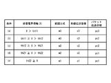
- FIG. 4 is a table showing an example of the relationship shown in FIG. 3 regarding the relationship between the received electric field information (X) output from the wireless transmission / reception circuit 25 and the modulation method, wireless transmission capacity, and packet transmission band at that time.
- the condition (a) in FIG. 4 indicates that when the received electric field information (X) is larger than the received electric field level th11, the modulation method is m3, the radio transmission capacity is c3, and the packet transmission band is pc3. ing.
- the radio transmission / reception circuit 25 generates the reception electric field information (X) by monitoring the reception electric field level of the radio transmission path 3 which changes every moment with the passage of time, and sequentially notifies the transmission band control circuit 26 and the modulation method control circuit 27. To do.
- the transmission band control circuit 26 monitors the reception electric field information (X) received from the wireless transmission / reception circuit 25 and detects that the reception electric field level becomes th11 at the time t11 in FIG. 3, the condition shown in FIG. From the state corresponding to (a), it is determined that the condition (b) in FIG. 4 is satisfied, and a transmission band control signal for reducing the packet transmission band from pc3 to pc2 is generated and notified to the transmission circuit 24.
- the transmission circuit 24 receives the transmission band control signal and outputs the amount of packet signal read from the high priority buffer 22 and the low priority buffer 23 so that the transmission band of the packet signal output to the wireless transmission / reception circuit 25 is equal to or less than pc2 in FIG. 3D.
- the packet signal is output to the wireless transmission / reception circuit 25 after adjustment. At this time, when it is detected that the packet transmission band indicated by the transmission band control signal has changed from pc3 to pc2, the packet signal being output to the wireless transmission / reception circuit 25 is sent without delay, and the transmission band is controlled to be suppressed. .
- the modulation scheme control circuit 27 monitors the received electric field information (X) received from the wireless transmission / reception circuit 25 and detects that the received electric field level is th11 at time t11 in FIG. It is determined that the condition (b) in FIG. 4 is satisfied from the state corresponding to the condition (a) in FIG. 4, but the condition (a) and the condition (b) in FIG. 4 are selected as shown in the graph of FIG. 3B. There is no change in the modulation scheme to be performed, and the modulation scheme m3 is maintained.
- the transmission band control circuit 26 and the modulation scheme control circuit 27 receive the received electric field information (X) received from the wireless transmission / reception circuit 25 at the time t12 in FIG. It is detected that the electric field level has become th12, and it is determined that the condition (c) in FIG. 4 has been met from the state corresponding to the condition (b) in FIG.
- the transmission band control signal generated by the transmission band control circuit 26 does not change depending on the state of the packet transmission band pc2, but the modulation scheme control circuit 27 selects the condition (b) and the condition (c) in FIG. Since the modulation schemes are different, a modulation scheme control signal for changing the modulation scheme from m3 to m2 is generated and notified to the wireless transmission / reception circuit 25.
- the wireless transmission / reception circuit 25 switches the modulation method of the wireless transmission path from m3 to m2 based on the modulation method control signal, and accordingly, the wireless transmission capacity is reduced from c3 to c2 as shown in FIG. 3C.
- the packet transmission band has already been reduced to pc2 at time t12, the packet signal received from the transmission circuit 24 is not affected by the fact that the radio transmission requirement is reduced from c3 to c2.
- the modulation scheme is changed in a situation where the reception electric field level of the wireless transmission path 3 is lowered by making a difference between the modulation control threshold serving as a reference for switching the modulation scheme and the band control threshold serving as a reference for switching the transmission band of the packet signal.
- the wireless transmission capacity is reduced.
- Control for reducing the transmission band of the packet signal transmitted to the wireless transmission path before the control for reduction can be performed.
- the reception electric field level of the radio transmission path is improved and the radio transmission path modulation method, radio transmission capacity, and packet signal transmission band are controlled in the direction of expanding the radio transmission capacity, packet signal transmission is performed.
- Control for expanding the wireless transmission capacity can be performed prior to control for expanding the band. Therefore, it is possible to avoid the loss of a packet signal with a high priority and the temporary fluctuation of the transmission delay time due to the change in the radio transmission capacity accompanying the change of the modulation method.
- the wireless transmission device may not necessarily be a device connected to another device by wire, and the wireless transmission device may be provided with voice input means and data input means. Good.
- the packet signal received from the wired transmission path 2 is divided into two priority levels via the priority determination circuit 21, and each of the high priority buffers 22, Alternatively, although stored in the low priority buffer 23, the priority level may not be two.
- the reception field level of the radio signal is used for determining the channel quality of the radio transmission path.
- the channel quality determination method is not limited to this method. For example, a bit error rate of a wireless line or an SN ratio (Signal Noise Ratio) may be used.
- It can be used for infrastructure communication equipment used by telecommunications carriers, especially fixed wireless transmission devices using microwaves, millimeter waves, and the like.
Abstract
Description
例えば、特許文献1には、適応変調制御により無線伝送路の伝送容量が変化するシステムにおいて、無線伝送容量を監視して無線伝送容量の変化に応じて無線伝送路に送出する信号帯域を制御する方法が開示されている。この方法を実行することにより、不要なトラフィック輻輳状態を回避し、重要トラフィックの伝送速度と伝送品質を維持することができる。 When the line quality of the radio transmission path is degraded, the adaptive modulation function that controls the radio modulation system is used to secure a reception electric field margin for maintaining the line and to maintain the important traffic transmission function. Various proposals have been made so far.
For example, in Patent Document 1, in a system in which the transmission capacity of a wireless transmission path is changed by adaptive modulation control, the wireless transmission capacity is monitored and a signal band transmitted to the wireless transmission path is controlled according to the change of the wireless transmission capacity. A method is disclosed. By executing this method, unnecessary traffic congestion can be avoided and the transmission speed and transmission quality of important traffic can be maintained.
以下、図面を参照して本発明の実施の形態について説明する。図1は本発明の一実施形態を示すブロック図である。 Embodiment 1
Embodiments of the present invention will be described below with reference to the drawings. FIG. 1 is a block diagram showing an embodiment of the present invention.
図2は本発明の一実施形態を示すブロック図である。適応変調機能を具備した無線伝送装置200は有線伝送路2と無線伝送路3に接続している。
無線伝送装置200は、優先度判定回路21、高優先バッファ22、低優先バッファ23、送信回路24、無線送受信回路25、伝送帯域制御回路26、及び変調方式制御回路27を備えている。
FIG. 2 is a block diagram showing an embodiment of the present invention. A
The
したがって、変調方式の変更に伴う無線伝送容量の変化によって、優先度の高いパケット信号の消失や伝送遅延時間の一時的な揺らぎを回避することができる。 As a result, when the reception electric field level of the wireless transmission path is lowered and the wireless transmission path modulation method, the wireless transmission capacity, and the packet signal transmission band are controlled in the direction of reducing the wireless transmission capacity, the wireless transmission capacity is reduced. Control for reducing the transmission band of the packet signal transmitted to the wireless transmission path before the control for reduction can be performed. In addition, when the reception electric field level of the radio transmission path is improved and the radio transmission path modulation method, radio transmission capacity, and packet signal transmission band are controlled in the direction of expanding the radio transmission capacity, packet signal transmission is performed. Control for expanding the wireless transmission capacity can be performed prior to control for expanding the band.
Therefore, it is possible to avoid the loss of a packet signal with a high priority and the temporary fluctuation of the transmission delay time due to the change in the radio transmission capacity accompanying the change of the modulation method.
例えば、本発明の実施の形態にかかる無線伝送装置は、必ずしも有線により他の機器に接続された装置でなくてもよく、当該無線伝送装置に音声入力手段やデータ入力手段が設けられていてもよい。
また、図2に示した本発明の実施の形態においては、有線伝送路2から受信したパケット信号は優先度判定回路21を介して2つの優先度レベルに分けられて、それぞれ高優先バッファ22、もしくは低優先バッファ23に格納しているが、優先度のレベル分けは2でなくともよい。
また、図2に示した本発明の一実施例においては、無線伝送路の回線品質の判定に無線信号の受信電界レベルを用いているが、回線品質の判定方式はこの方法に限るわけではなく、たとえば無線回線のビットエラーレートや、SN比(Signal Noise Ratio)を用いても良い。 Note that the present invention is not limited to the above-described embodiment, and can be changed as appropriate without departing from the spirit of the present invention.
For example, the wireless transmission device according to the embodiment of the present invention may not necessarily be a device connected to another device by wire, and the wireless transmission device may be provided with voice input means and data input means. Good.
In the embodiment of the present invention shown in FIG. 2, the packet signal received from the wired
In the embodiment of the present invention shown in FIG. 2, the reception field level of the radio signal is used for determining the channel quality of the radio transmission path. However, the channel quality determination method is not limited to this method. For example, a bit error rate of a wireless line or an SN ratio (Signal Noise Ratio) may be used.
3 無線伝送路
11 送信処理部
12 無線送受信部
13 伝送帯域制御部
14 変調方式制御部
21 優先度判定回路
22 高優先バッファ
23 低優先バッファ
24 送信回路
25 無線送受信回路
26 伝送帯域制御回路
27 変調方式制御回路
100 無線伝送装置
200 無線伝送装置 2 wired
Claims (6)
- 無線通信の通信品質情報と、予め定めた帯域制御閾値との比較結果に基づいて伝送帯域を決定する伝送帯域制御手段と、
前記通信品質情報と、予め定めた変調制御閾値との比較結果に基づいて変調方式を決定する変調方式制御手段と、
前記伝送帯域制御手段により決定された伝送帯域に基づいてパケット信号の伝送帯域を制御し、パケット信号を出力する送信処理手段と、
前記送信処理手段より出力されたパケット信号を、前記変調方式制御手段により決定された変調方式に基づいて変調処理を行う無線送受信手段を備え、
前記帯域制御閾値と、前記変調制御閾値は異なる値である無線伝送装置。 Transmission band control means for determining a transmission band based on a comparison result between communication quality information of wireless communication and a predetermined band control threshold;
Modulation scheme control means for determining a modulation scheme based on a comparison result between the communication quality information and a predetermined modulation control threshold;
Transmission processing means for controlling the transmission band of the packet signal based on the transmission band determined by the transmission band control means and outputting the packet signal;
Radio transmission / reception means for performing a modulation process on the packet signal output from the transmission processing means based on the modulation scheme determined by the modulation scheme control means,
A wireless transmission apparatus in which the band control threshold and the modulation control threshold are different values. - 通信品質が低下しているときに、変調方式の切り替えより先に伝送帯域の切り替えが行われるように、前記帯域制御閾値と前記変調制御閾値が設定されていることを特徴とする請求項1記載の無線伝送装置。 2. The bandwidth control threshold and the modulation control threshold are set so that transmission band switching is performed prior to modulation system switching when communication quality is deteriorated. Wireless transmission equipment.
- 前記通信品質が向上しているときに、伝送帯域の切り替えより先に変調方式の切り替えが行われるように、前記帯域制御閾値と前記変調制御閾値が設定されていることを特徴とする請求項2記載の無線伝送装置。 The band control threshold and the modulation control threshold are set so that the modulation scheme is switched before the transmission band is switched when the communication quality is improved. The wireless transmission device described.
- 無線通信の通信品質情報に基づいて伝送帯域を決定する伝送帯域制御手段と、
前記通信品質情報に基づいて変調方式を決定する変調方式制御手段と、
前記伝送帯域制御手段により決定された伝送帯域に基づいてパケット信号の伝送帯域を制御し、パケット信号を出力する送信処理手段と、
前記送信処理手段より出力されたパケット信号を、前記変調方式制御手段により決定された変調方式に基づいて変調処理を行う無線送受信手段を備え、
前記伝送帯域制御手段と前記変調方式制御手段は、通信品質が低下しているときに、変調方式の切り替えより先に伝送帯域の切り替えが行われるように、伝送帯域及び変調方式を決定する無線伝送装置。 Transmission band control means for determining a transmission band based on communication quality information of wireless communication;
Modulation scheme control means for determining a modulation scheme based on the communication quality information;
Transmission processing means for controlling the transmission band of the packet signal based on the transmission band determined by the transmission band control means and outputting the packet signal;
Radio transmission / reception means for performing a modulation process on the packet signal output from the transmission processing means based on the modulation scheme determined by the modulation scheme control means,
The transmission band control means and the modulation scheme control means determine the transmission band and the modulation scheme so that the transmission band is switched before the switching of the modulation scheme when the communication quality is deteriorated. apparatus. - 前記無線通信の通信品質情報として、無線通信の電界レベルを用いることを特徴とする請求項1~4のいずれか1項に記載の無線伝送装置。 The wireless transmission device according to any one of claims 1 to 4, wherein an electric field level of wireless communication is used as communication quality information of the wireless communication.
- 無線通信の通信品質情報を取得し、取得した通信品質情報に基づいて伝送帯域と変調方式を決定する無線伝送帯域制御方法であって、
通信品質が低下しているときに、変調方式の切り替えより先に伝送帯域の切り替えが行われるように、前記伝送帯域及び前記変調方式を決定する無線伝送帯域制御方法。 A wireless transmission band control method for acquiring communication quality information of wireless communication and determining a transmission band and a modulation method based on the acquired communication quality information,
A radio transmission band control method for determining the transmission band and the modulation scheme so that the transmission band is switched before the modulation scheme switching when the communication quality is deteriorated.
Priority Applications (3)
| Application Number | Priority Date | Filing Date | Title |
|---|---|---|---|
| EP13817624.3A EP2874364A4 (en) | 2012-07-12 | 2013-07-04 | Wireless transfer system, and method for control of wireless transfer band |
| US14/413,914 US9571237B2 (en) | 2012-07-12 | 2013-07-04 | Wireless transfer device and method for control of wireless transfer band |
| IN160DEN2015 IN2015DN00160A (en) | 2012-07-12 | 2015-01-07 |
Applications Claiming Priority (2)
| Application Number | Priority Date | Filing Date | Title |
|---|---|---|---|
| JP2012-156324 | 2012-07-12 | ||
| JP2012156324 | 2012-07-12 |
Publications (1)
| Publication Number | Publication Date |
|---|---|
| WO2014010209A1 true WO2014010209A1 (en) | 2014-01-16 |
Family
ID=49915692
Family Applications (1)
| Application Number | Title | Priority Date | Filing Date |
|---|---|---|---|
| PCT/JP2013/004159 WO2014010209A1 (en) | 2012-07-12 | 2013-07-04 | Wireless transfer system, and method for control of wireless transfer band |
Country Status (4)
| Country | Link |
|---|---|
| US (1) | US9571237B2 (en) |
| EP (1) | EP2874364A4 (en) |
| IN (1) | IN2015DN00160A (en) |
| WO (1) | WO2014010209A1 (en) |
Citations (4)
| Publication number | Priority date | Publication date | Assignee | Title |
|---|---|---|---|---|
| JP2006086626A (en) * | 2004-09-14 | 2006-03-30 | Hitachi Kokusai Electric Inc | Packet wireless communication system |
| WO2011074681A1 (en) * | 2009-12-14 | 2011-06-23 | 日本電気株式会社 | Communication apparatus and communication control method |
| JP2011239322A (en) | 2010-05-13 | 2011-11-24 | Nec Corp | NETWORK REPEATER AND QoS CONTROL METHOD |
| JP2012064992A (en) * | 2008-12-16 | 2012-03-29 | Nec Corp | Communication apparatus, data rate control method and communication system |
Family Cites Families (5)
| Publication number | Priority date | Publication date | Assignee | Title |
|---|---|---|---|---|
| US7145880B2 (en) * | 2002-04-24 | 2006-12-05 | Cingular Wireless Ii, Llc | System and method for channel assignment with adaptive modulation in wireless communications |
| US20070121738A1 (en) * | 2003-09-30 | 2007-05-31 | Matsushita Electric Industrial Co., Ltd. | Transmission apparatus and peak suppression method |
| US7047006B2 (en) * | 2004-04-28 | 2006-05-16 | Motorola, Inc. | Method and apparatus for transmission and reception of narrowband signals within a wideband communication system |
| JP2007150800A (en) * | 2005-11-29 | 2007-06-14 | Kyocera Corp | Radio base station apparatus and control method thereof |
| US8681619B2 (en) * | 2010-04-08 | 2014-03-25 | Landis+Gyr Technologies, Llc | Dynamic modulation selection |
-
2013
- 2013-07-04 EP EP13817624.3A patent/EP2874364A4/en not_active Withdrawn
- 2013-07-04 WO PCT/JP2013/004159 patent/WO2014010209A1/en active Application Filing
- 2013-07-04 US US14/413,914 patent/US9571237B2/en active Active
-
2015
- 2015-01-07 IN IN160DEN2015 patent/IN2015DN00160A/en unknown
Patent Citations (4)
| Publication number | Priority date | Publication date | Assignee | Title |
|---|---|---|---|---|
| JP2006086626A (en) * | 2004-09-14 | 2006-03-30 | Hitachi Kokusai Electric Inc | Packet wireless communication system |
| JP2012064992A (en) * | 2008-12-16 | 2012-03-29 | Nec Corp | Communication apparatus, data rate control method and communication system |
| WO2011074681A1 (en) * | 2009-12-14 | 2011-06-23 | 日本電気株式会社 | Communication apparatus and communication control method |
| JP2011239322A (en) | 2010-05-13 | 2011-11-24 | Nec Corp | NETWORK REPEATER AND QoS CONTROL METHOD |
Non-Patent Citations (1)
| Title |
|---|
| See also references of EP2874364A4 |
Also Published As
| Publication number | Publication date |
|---|---|
| EP2874364A4 (en) | 2016-03-09 |
| US9571237B2 (en) | 2017-02-14 |
| US20150172008A1 (en) | 2015-06-18 |
| EP2874364A1 (en) | 2015-05-20 |
| IN2015DN00160A (en) | 2015-06-12 |
Similar Documents
| Publication | Publication Date | Title |
|---|---|---|
| KR100963660B1 (en) | Method, apparatus and computer program to dynamically adjust segmentation at a protocol layer, such as at the medium access controlMAC layer | |
| EP2080326B1 (en) | System and method of load dependent rate control | |
| US6845088B2 (en) | System and method for fast dynamic link adaptation | |
| WO2006012211B1 (en) | A system and method for adaptive rate selection for wireless networks | |
| EP3602877A1 (en) | Wireless telecommunications apparatus and methods | |
| CA2534977A1 (en) | A system and method for selecting size of dynamic voice jitter buffer for packet switched communications system | |
| US20200296629A1 (en) | Back-pressure control in a telecommunications network | |
| WO2007023913A1 (en) | Communication control apparatus, communication terminal apparatus, wireless communication system, and transmitting method | |
| JP5048763B2 (en) | Mobile device power control for dual transfer mode (DTM) | |
| US20190281445A1 (en) | Wireless communications system, base station, terminal, and process method | |
| US10785677B2 (en) | Congestion control in a telecommunications network | |
| CN114375545A (en) | Interference suppression | |
| CN104969629A (en) | Method and device for adjusting sending power | |
| JP4905334B2 (en) | Communication apparatus and adaptive modulation method | |
| WO2014010209A1 (en) | Wireless transfer system, and method for control of wireless transfer band | |
| EP4016966A1 (en) | Dynamic adaptation of time-aware communications in time-sensitive systems | |
| WO2012173036A1 (en) | Control method for adaptive modulation circuit and wireless transmission device provided with adaptive modulation circuit | |
| JP4894507B2 (en) | Base station apparatus, mobile communication system, and scheduling request control method used therefor | |
| JP2011244077A (en) | Radio communication equipment, radio communication system, and communication control method | |
| RU2562812C2 (en) | Wireless transmission device, wireless transmission system and method of controlling wireless transmission device | |
| WO2019015758A1 (en) | Processing and transport of fronthaul communications | |
| WO2018116965A1 (en) | Wireless communication device, wireless communication system, and wireless communication method | |
| JP5093124B2 (en) | Wireless transmission apparatus, control method thereof, and program | |
| JP2007306623A (en) | Wireless base station, mobile terminal, wireless communication system, and wireless communication method | |
| CN113691350B (en) | Combined scheduling method and system of eMBB and URLLC |
Legal Events
| Date | Code | Title | Description |
|---|---|---|---|
| 121 | Ep: the epo has been informed by wipo that ep was designated in this application |
Ref document number: 13817624 Country of ref document: EP Kind code of ref document: A1 |
|
| REEP | Request for entry into the european phase |
Ref document number: 2013817624 Country of ref document: EP |
|
| WWE | Wipo information: entry into national phase |
Ref document number: 2013817624 Country of ref document: EP |
|
| WWE | Wipo information: entry into national phase |
Ref document number: 14413914 Country of ref document: US |
|
| NENP | Non-entry into the national phase |
Ref country code: DE |
|
| NENP | Non-entry into the national phase |
Ref country code: JP |