WO2014002944A1 - Wireless communication system, wireless base station device, user terminal, and communication control method - Google Patents
Wireless communication system, wireless base station device, user terminal, and communication control method Download PDFInfo
- Publication number
- WO2014002944A1 WO2014002944A1 PCT/JP2013/067238 JP2013067238W WO2014002944A1 WO 2014002944 A1 WO2014002944 A1 WO 2014002944A1 JP 2013067238 W JP2013067238 W JP 2013067238W WO 2014002944 A1 WO2014002944 A1 WO 2014002944A1
- Authority
- WO
- WIPO (PCT)
- Prior art keywords
- rate matching
- cell
- transmission
- base station
- user terminal
- Prior art date
Links
Images


Classifications
-
- H—ELECTRICITY
- H04—ELECTRIC COMMUNICATION TECHNIQUE
- H04W—WIRELESS COMMUNICATION NETWORKS
- H04W72/00—Local resource management
- H04W72/12—Wireless traffic scheduling
-
- H—ELECTRICITY
- H04—ELECTRIC COMMUNICATION TECHNIQUE
- H04L—TRANSMISSION OF DIGITAL INFORMATION, e.g. TELEGRAPHIC COMMUNICATION
- H04L51/00—User-to-user messaging in packet-switching networks, transmitted according to store-and-forward or real-time protocols, e.g. e-mail
- H04L51/21—Monitoring or handling of messages
- H04L51/222—Monitoring or handling of messages using geographical location information, e.g. messages transmitted or received in proximity of a certain spot or area
-
- H—ELECTRICITY
- H04—ELECTRIC COMMUNICATION TECHNIQUE
- H04W—WIRELESS COMMUNICATION NETWORKS
- H04W72/00—Local resource management
- H04W72/50—Allocation or scheduling criteria for wireless resources
- H04W72/52—Allocation or scheduling criteria for wireless resources based on load
-
- H—ELECTRICITY
- H04—ELECTRIC COMMUNICATION TECHNIQUE
- H04B—TRANSMISSION
- H04B7/00—Radio transmission systems, i.e. using radiation field
- H04B7/02—Diversity systems; Multi-antenna system, i.e. transmission or reception using multiple antennas
- H04B7/022—Site diversity; Macro-diversity
- H04B7/024—Co-operative use of antennas of several sites, e.g. in co-ordinated multipoint or co-operative multiple-input multiple-output [MIMO] systems
-
- H—ELECTRICITY
- H04—ELECTRIC COMMUNICATION TECHNIQUE
- H04L—TRANSMISSION OF DIGITAL INFORMATION, e.g. TELEGRAPHIC COMMUNICATION
- H04L1/00—Arrangements for detecting or preventing errors in the information received
- H04L1/0001—Systems modifying transmission characteristics according to link quality, e.g. power backoff
- H04L1/0009—Systems modifying transmission characteristics according to link quality, e.g. power backoff by adapting the channel coding
- H04L1/0013—Rate matching, e.g. puncturing or repetition of code symbols
-
- H—ELECTRICITY
- H04—ELECTRIC COMMUNICATION TECHNIQUE
- H04L—TRANSMISSION OF DIGITAL INFORMATION, e.g. TELEGRAPHIC COMMUNICATION
- H04L1/00—Arrangements for detecting or preventing errors in the information received
- H04L1/004—Arrangements for detecting or preventing errors in the information received by using forward error control
- H04L1/0056—Systems characterized by the type of code used
- H04L1/0067—Rate matching
-
- H—ELECTRICITY
- H04—ELECTRIC COMMUNICATION TECHNIQUE
- H04L—TRANSMISSION OF DIGITAL INFORMATION, e.g. TELEGRAPHIC COMMUNICATION
- H04L5/00—Arrangements affording multiple use of the transmission path
- H04L5/003—Arrangements for allocating sub-channels of the transmission path
- H04L5/0032—Distributed allocation, i.e. involving a plurality of allocating devices, each making partial allocation
- H04L5/0035—Resource allocation in a cooperative multipoint environment
-
- H—ELECTRICITY
- H04—ELECTRIC COMMUNICATION TECHNIQUE
- H04L—TRANSMISSION OF DIGITAL INFORMATION, e.g. TELEGRAPHIC COMMUNICATION
- H04L5/00—Arrangements affording multiple use of the transmission path
- H04L5/003—Arrangements for allocating sub-channels of the transmission path
- H04L5/0053—Allocation of signaling, i.e. of overhead other than pilot signals
-
- H—ELECTRICITY
- H04—ELECTRIC COMMUNICATION TECHNIQUE
- H04L—TRANSMISSION OF DIGITAL INFORMATION, e.g. TELEGRAPHIC COMMUNICATION
- H04L5/00—Arrangements affording multiple use of the transmission path
- H04L5/0091—Signaling for the administration of the divided path
- H04L5/0094—Indication of how sub-channels of the path are allocated
-
- H—ELECTRICITY
- H04—ELECTRIC COMMUNICATION TECHNIQUE
- H04L—TRANSMISSION OF DIGITAL INFORMATION, e.g. TELEGRAPHIC COMMUNICATION
- H04L5/00—Arrangements affording multiple use of the transmission path
- H04L5/0091—Signaling for the administration of the divided path
- H04L5/0096—Indication of changes in allocation
- H04L5/0098—Signalling of the activation or deactivation of component carriers, subcarriers or frequency bands
-
- H—ELECTRICITY
- H04—ELECTRIC COMMUNICATION TECHNIQUE
- H04L—TRANSMISSION OF DIGITAL INFORMATION, e.g. TELEGRAPHIC COMMUNICATION
- H04L67/00—Network arrangements or protocols for supporting network services or applications
- H04L67/50—Network services
- H04L67/52—Network services specially adapted for the location of the user terminal
-
- H—ELECTRICITY
- H04—ELECTRIC COMMUNICATION TECHNIQUE
- H04L—TRANSMISSION OF DIGITAL INFORMATION, e.g. TELEGRAPHIC COMMUNICATION
- H04L69/00—Network arrangements, protocols or services independent of the application payload and not provided for in the other groups of this subclass
- H04L69/24—Negotiation of communication capabilities
-
- H—ELECTRICITY
- H04—ELECTRIC COMMUNICATION TECHNIQUE
- H04W—WIRELESS COMMUNICATION NETWORKS
- H04W16/00—Network planning, e.g. coverage or traffic planning tools; Network deployment, e.g. resource partitioning or cells structures
- H04W16/24—Cell structures
- H04W16/28—Cell structures using beam steering
-
- H—ELECTRICITY
- H04—ELECTRIC COMMUNICATION TECHNIQUE
- H04W—WIRELESS COMMUNICATION NETWORKS
- H04W72/00—Local resource management
- H04W72/20—Control channels or signalling for resource management
- H04W72/23—Control channels or signalling for resource management in the downlink direction of a wireless link, i.e. towards a terminal
-
- H—ELECTRICITY
- H04—ELECTRIC COMMUNICATION TECHNIQUE
- H04L—TRANSMISSION OF DIGITAL INFORMATION, e.g. TELEGRAPHIC COMMUNICATION
- H04L1/00—Arrangements for detecting or preventing errors in the information received
- H04L2001/0092—Error control systems characterised by the topology of the transmission link
-
- H—ELECTRICITY
- H04—ELECTRIC COMMUNICATION TECHNIQUE
- H04L—TRANSMISSION OF DIGITAL INFORMATION, e.g. TELEGRAPHIC COMMUNICATION
- H04L5/00—Arrangements affording multiple use of the transmission path
- H04L5/003—Arrangements for allocating sub-channels of the transmission path
- H04L5/0058—Allocation criteria
-
- H—ELECTRICITY
- H04—ELECTRIC COMMUNICATION TECHNIQUE
- H04L—TRANSMISSION OF DIGITAL INFORMATION, e.g. TELEGRAPHIC COMMUNICATION
- H04L5/00—Arrangements affording multiple use of the transmission path
- H04L5/003—Arrangements for allocating sub-channels of the transmission path
- H04L5/0078—Timing of allocation
- H04L5/0085—Timing of allocation when channel conditions change
-
- H—ELECTRICITY
- H04—ELECTRIC COMMUNICATION TECHNIQUE
- H04L—TRANSMISSION OF DIGITAL INFORMATION, e.g. TELEGRAPHIC COMMUNICATION
- H04L5/00—Arrangements affording multiple use of the transmission path
- H04L5/003—Arrangements for allocating sub-channels of the transmission path
- H04L5/0078—Timing of allocation
- H04L5/0087—Timing of allocation when data requirements change
-
- H—ELECTRICITY
- H04—ELECTRIC COMMUNICATION TECHNIQUE
- H04L—TRANSMISSION OF DIGITAL INFORMATION, e.g. TELEGRAPHIC COMMUNICATION
- H04L51/00—User-to-user messaging in packet-switching networks, transmitted according to store-and-forward or real-time protocols, e.g. e-mail
- H04L51/04—Real-time or near real-time messaging, e.g. instant messaging [IM]
- H04L51/043—Real-time or near real-time messaging, e.g. instant messaging [IM] using or handling presence information
-
- H—ELECTRICITY
- H04—ELECTRIC COMMUNICATION TECHNIQUE
- H04W—WIRELESS COMMUNICATION NETWORKS
- H04W4/00—Services specially adapted for wireless communication networks; Facilities therefor
- H04W4/02—Services making use of location information
Definitions
- the present invention relates to a radio communication system, a radio base station apparatus, a user terminal, and a communication control method in a next generation mobile communication system.
- HSDPA High Speed Downlink Access Access
- HSUPA High SpeckUsedWedPickUsedWidePac
- CDMA Wideband Code Division Multiple Access
- the third generation system can achieve a maximum transmission rate of about 2 Mbps on the downlink using generally a fixed bandwidth of 5 MHz.
- a transmission rate of about 300 Mbps at the maximum in the downlink and about 75 Mbps at the maximum in the uplink can be realized using a variable band of 1.4 MHz to 20 MHz.
- LTE-A LTE advanced or LTE enhancement
- Inter-cell orthogonalization has been proposed as one of promising technologies for further improving system performance for LTE systems.
- LTE-A orthogonalization within a cell is realized by orthogonal multi-access for both uplink and downlink. That is, in the downlink, the user terminals UE (User Equipment) are orthogonalized in the frequency domain.
- UE User Equipment
- W-CDMA interference randomization is performed between cells by repeating one-cell frequency.
- CoMP coordinated multi-point transmission / reception
- a plurality of cells perform transmission / reception signal processing in cooperation with one or a plurality of user terminals UE.
- Application of such CoMP transmission / reception technology is expected to improve the throughput characteristics of the user terminal UE located particularly at the cell edge.
- joint transmission Joint transmission
- DPS Dynamic Point
- CoMP sets a plurality of cells that perform data transmission in a coordinated manner.
- the user terminal UE that receives the CoMP transmitted data needs to perform rate matching in order to finely adjust the bit rate of the received data.
- rate matching refers to performing an iterative process or a puncturing process on the decoded bits of the transport channel.
- the arrangement (more specifically, the number and position) of the resource elements (RE) to which the physical downlink shared channel (PDSCH: Physical Downlink Shared Channel) is allocated is different. .
- the physical downlink control channel (PDCCH: Physical Downlink Control Channel)
- PDSCH Physical Downlink Control Channel
- a different number of symbols can be set for each cell (the first OFDM symbol to the first 3 OFDM symbols of the subframe). For this reason, the number of REs to which the PDSCH is allocated increases or decreases depending on the number of PDCCH symbols.
- the position of RE set based on cell ID (cell index) changes in CRS (Common Reference Signal). For this reason, the position of the RE to which the PDSCH is allocated changes according to the cell ID of the cells constituting the CoMP set.
- a radio base station apparatus In order to perform rate matching appropriately in the user terminal UE, it is necessary to identify an RE (PDSCH allocation area) to which the PDSCH is allocated for each cell constituting the CoMP set. For this reason, it is preferable that a radio base station apparatus notifies the information (rate matching information) required for rate matching including the information for identifying the allocation area
- the rate matching information changes corresponding to the CoMP form. For this reason, rate matching information to be notified to the user terminal UE is complicated.
- CoMP transmission it is possible to set different CoMP sets for different frequency bands. In this case, the rate matching information to be notified to the user terminal UE becomes more complicated.
- the present invention has been made in view of such circumstances, and even when applying CoMP transmission / reception technology, a radio communication system, a radio base station apparatus, a user terminal, and communication control capable of efficiently signaling information necessary for rate matching It aims to provide a method.
- a radio communication system is a radio communication system including a plurality of radio base station apparatuses each forming a cell and a user terminal connected to each radio base station apparatus via a radio link.
- the radio base station apparatus is required to correspond to the scheduler that schedules CoMP transmission that performs coordinated multipoint transmission to the user terminal as a transmission point together with other radio base station apparatuses, and the transmission mode of CoMP transmission.
- a generation unit Based on a table in which a rate matching pattern is mapped to bit data, a generation unit that generates downlink control information in which the rate matching pattern is incorporated in a physical downlink control channel, and transmits the physical downlink control channel A transmitter for transmitting the physical downlink shared data channel.
- the user terminal receives the physical downlink control channel and receives the physical downlink shared data channel from all the radio base station apparatuses that perform CoMP transmission and the received physical downlink control channel.
- a determination unit that identifies the rate matching pattern incorporated in the included downlink control information based on a table having the same contents as the radio base station device, and the downlink using the identified rate matching pattern And a rate matching unit that performs rate matching of the shared data channel.
- the radio base station apparatus of the present invention is a radio base station apparatus to which a user terminal connects via a radio link, and performs coordinated multipoint transmission to the user terminal as a transmission point together with other radio base station apparatuses.
- Downlink in which the rate matching pattern is incorporated into a physical downlink control channel based on a scheduler that schedules CoMP transmission and a table in which a rate matching pattern necessary for the transmission form of CoMP transmission is mapped to bit data
- a generation unit that generates control information, and a transmission unit that transmits the physical downlink control channel and transmits the physical downlink shared data channel are provided.
- a user terminal is a user terminal that is connected to a plurality of radio base station apparatuses each forming a cell via a radio link, and receives a physical downlink control channel from the radio base station apparatus.
- a receiving unit that receives physical downlink shared data channels from all the radio base station devices that perform CoMP transmission, and a rate matching pattern that is incorporated in downlink control information included in the received physical downlink control channel,
- a determination unit that identifies based on a table prepared in advance; and a rate matching unit that performs rate matching of the downlink shared data channel using the identified rate matching pattern.
- the required rate matching pattern corresponding to the form is bit data Characterized in that it is mapped.
- the communication control method of the present invention is a communication control in a radio communication system comprising a plurality of radio base station apparatuses each forming a cell and a user terminal connected to each radio base station apparatus via a radio link.
- a method for scheduling CoMP transmission in which the plurality of radio base station apparatuses serve as transmission points for the multi-point transmission to the user terminal, and a rate matching necessary for a transmission form of CoMP transmission
- Generating downlink control information in which the rate matching pattern is incorporated in a physical downlink control channel based on a table in which a pattern is mapped to bit data; and transmitting the physical downlink control channel and a physical downlink Transmitting a shared data channel; and
- the rate matching pattern incorporated in the downlink control information The terminal, characterized by comprising a step of identifying, based on said table having the same content as the radio base station apparatus.
- CoMP transmission / reception cooperative multipoint transmission / reception
- rate matching object in case CoMP transmission / reception technique is applied.
- rate matching object in the case of carrying out joint transmission including the cell of MBSFN or New carrier type.
- FIG. 1 is a diagram for explaining a CoMP transmission / reception (cooperative multipoint transmission / reception) technique.
- FIG. 1A is a conceptual diagram of joint transmission (hereinafter referred to as “CoMP transmission (JT)” as appropriate), which is one of CoMP transmissions.
- the same shared data channel (PDSCH) is simultaneously transmitted from a plurality of cells to one user terminal UE in one subframe.
- the user terminal UE receives PDSCH from all transmission cells of cell 0, cell 1 and cell 2 in one subframe.
- the user terminal UE receives the PDSCH jointly transmitted from the cell 0, the cell 1, and the cell 2 based on the PDCCH shared by the cell 0, the cell 1, and the cell 2.
- FIG. 1B is a conceptual diagram of DPS (hereinafter, referred to as “CoMP transmission (DPS)” as appropriate), which is one of CoMP transmissions.
- DPS CoMP transmission
- the transmission cell for one user terminal UE is dynamically switched to transmit the PDSCH.
- the user terminal UE receives the PDSCH transmitted from the cell 0, the cell 1 and the cell 2 based on the PDCCH transmitted from the cell 0, the cell 1 and the cell 2, respectively.
- the radio base station apparatus eNB feeds back quality information of each cell from the user terminal UE. Then, the radio base station apparatus eNB obtains quality information for each cell (for example, RSRP (Reference Signal Received Power), RSRQ (Reference Signal Received Quality), or SINR (Signal Interference Plus) Noise Ratio Ratio).
- RSRP Reference Signal Received Power
- RSRQ Reference Signal Received Quality
- SINR Signal Interference Plus Noise Ratio Ratio
- the radio base station apparatus eNB determines that the user terminal UE exists at the cell edge. In this case, the radio base station apparatus eNB applies CoMP transmission.
- the radio base station apparatus eNB is close to the radio base station apparatus eNB forming any cell. Determines that the user terminal UE exists near the center of a cell with high reception quality. In this case, high reception quality can be maintained without applying CoMP transmission.
- the user terminal UE feeds back channel state information for each of a plurality of cells to the radio base station apparatus eNB (the radio base station apparatus eNB of the serving cell).
- the radio base station apparatus eNB the radio base station apparatus eNB of the serving cell.
- the user terminal UE feeds back channel state information of the serving cell to the radio base station apparatus eNB.
- FIG. 2A shows an example of a frame configuration of a subframe of each cell (cell 0 to cell 2) constituting the CoMP set.
- 2B shows a rate matching target when joint transmission is performed from cell 0 and cell 1 shown in FIG. 2A.
- the horizontal axis indicates time
- the vertical axis indicates frequency. The same applies to FIG.
- the areas to which PDCCH is allocated are different.
- the first OFDM (Orthogonal Frequency Division Multiple Access) symbol is assigned in cell 0
- the first and second OFDM symbols are assigned in cell 1
- the first to third OFDM symbols are assigned in cell 2 as PDCCH allocation regions. It shows about the case where is assigned.
- CRSs are arranged in different REs according to cell IDs.
- the PDSCH is assigned to REs in which the PDCCH and CRS of the subframes of the cell 0 to the cell 2 are not arranged. That is, the PDSCH allocation region is different for each cell constituting the CoMP set.
- the user terminal UE When receiving data from each cell, the user terminal UE performs rate matching for the RE to which the PDSCH is assigned in the subframe of each cell. For example, when receiving data from cell 0, the user terminal UE performs rate matching for REs to which the PDCCH is assigned (RE of the first OFDM symbol) and REs other than the RE to which the CRS is assigned. The same applies when data is received from cell 1 and cell 2.
- a PDSCH that is a rate matching target when joint transmission is performed from the cell 0 and the cell 1 to the user terminal UE will be considered.
- the PDSCH is assigned to an RE to which no PDCCH and CRS are assigned in both the cell 0 and the cell 1.
- the user terminal UE performs rate matching for REs to which the PDCCH is assigned (REs of the first OFDM symbol and the second OFDM symbol) and REs other than the RE to which the CRS is assigned.
- MBMS Multimedia Broadcast Multicast Service
- MBSFN MBMS Single Frequency Network
- a plurality of radio base station apparatuses eNB configuring a network simultaneously transmits the same signal, whereby a user terminal UE transmits a signal transmitted from each radio base station apparatus eNB to RF (Radio Frequency). It is a method that can be synthesized.
- a carrier type that does not have an existing PDCCH allocation area in a subframe is considered as a frame configuration.
- this New carrier type subframe it is assumed that no CRS is allocated and PDSCH is allocated to all REs. Note that this New carrier type subframe can also be referred to as an Additive carrier type subframe.
- FIG. 3 is an explanatory diagram of a rate matching target when joint transmission is performed including an MBSFN or New carrier type cell.
- FIG. 3A shows a frame configuration of the MBSFN subframe.
- FIG. 3B shows a frame structure of a New carrier type subframe.
- FIG. 3C illustrates a PDSCH that is a rate matching target when joint transmission is performed including an MBSFN subframe or a new carrier type cell.
- FIG. 3A shows a case where one OFDM symbol is designated as a PDCCH allocation area.
- an RE other than the PDCCH allocation area is defined as the PDSCH allocation area.
- no CRS is assigned to the PDSCH allocation area. For this reason, in the MBSFN subframe, the PDSCH can be assigned to all REs after the second OFDM symbol or the third OFDM symbol.
- the MBSFN subframe is selectively set to subframes other than subframes # 0, # 4, # 5, and # 9 among subframes # 0 to # 9 constituting the radio frame. That is, the radio base station apparatus eNB can selectively set MBSFN subframes in subframes # 1 to # 3 and # 6 to # 8.
- the PDSCH used as the rate matching object in the case of carrying out joint transmission from this cell 2 and the cell 1 shown in FIG. 2 to the user terminal UE is demonstrated.
- the PDSCH is assigned to an RE to which no PDCCH and CRS are assigned in both the cell 1 and the cell 2.
- the PDCCH and CRS are not allocated to REs after 2 OFDM symbols in the MBSFN subframe and the new carrier type subframe of cell 2. For this reason, the RE to which the PDSCH is assigned in the subframe of cell 1 is the target of rate matching.
- carrier aggregation CA: Carrier Aggregation
- CC Component Carrier
- the PDCCH of one primary cell is different from the PDSCH of a plurality of CCs (one primary cell + maximum four secondary cells).
- Cross-carrier scheduling that performs scheduling is employed.
- the details of the downlink control information transmitted by the PDCCH are defined as a DCI (Downlink Control Information) format.
- the DCI of the secondary cell PDCCH is allocated to the PDCCH allocation region (radio resources from the first OFDM symbol to a maximum of 3 OFDM symbols) in the primary cell.
- CIF Cell Index Field
- a cell index is defined in DCI so that it can be identified which cell is the PDCCH for receiving the PDSCH.
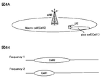
- a case where CA is applied in the system configuration (HetNeT environment) shown in FIG. 4A will be considered.
- a macro cell (cell 0) having a wide coverage area and a pico cell (cell 1) having a local coverage area in the coverage area of the macro cell (cell 0) are arranged.
- the pico cell (cell 1) has a lower transmission power than the macro cell (cell 0), and can also be referred to as a low power cell.
- frequency band 1 is assigned to the macro cell (cell 0)
- frequency band 2 different from frequency band 1 is assigned to the pico cell (cell 1).
- the user terminal UE notifies its own terminal capability (UE Capability) to the radio base station apparatus eNB in the primary cell (Pcell) in order to establish communication (RRC Connection).
- the radio base station apparatus eNB of the primary cell grasps the communication capability of the connected user terminal UE based on the notified terminal capability.
- the radio base station apparatus eNB transmits control information including the following five pieces of information to RRC (Radio Resource Control). Notify by signaling.
- Secondary cell (Scell) index Physical cell ID and downlink carrier frequency CRS port number MBSFN subframe configuration and subframe offset PDSCH start symbol
- PDCCH (DCI) for PDSCH transmitted from each cell Can be transmitted using the PDCCH resource of cell 0 serving as the primary cell.
- FIG. 5C is a conceptual diagram of the DCI format included in the PDCCH, and shows a state in which bit data indicating a cell in CA is described in the CIF. As shown in FIG. 5, 3 bits are allocated to the CIF.
- the user terminal UE when bit information (000) is specified in the CIF included in the DCI of the received PDCCH, the user terminal UE receives the PDSCH of cell 0 as the PDCCH. Can be recognized as a PDCCH.
- bit information (001) when bit information (001) is specified in the CIF included in the DCI of the received PDCCH, the user terminal UE can recognize that the PDCCH is a PDCCH for receiving the PDSCH of the cell 1.
- the radio base station apparatus eNB notifies information required for rate matching (rate matching information).
- rate matching information the notification of rate matching information to the user terminal UE is not defined.
- the present inventors have focused on the fact that rate matching information can be notified to the user terminal UE by using DCI defined in PDCCH even when CoMP transmission / reception technology is applied, and have reached the present invention.
- the gist of the present invention is based on a rate matching table in which a rate matching pattern necessary for the CoMP transmission mode is mapped to bit data in the radio base station apparatus eNB when CoMP transmission / reception technology is applied. , Generating DCI including a rate matching pattern in PDCCH, transmitting this PDCCH and transmitting PDSCH, and setting the rate matching pattern embedded in DCI in user terminal UE to the same content as radio base station apparatus eNB It is specified based on the matching table.
- the PDCCH including DCI incorporating a rate matching pattern corresponding to the CoMP transmission mode is transmitted to the user terminal UE.
- the rate matching pattern incorporated in DCI is specified based on the rate matching table of the same content as the radio base station apparatus eNB. For this reason, even when CoMP transmission / reception technology is applied, it is possible to efficiently signal information necessary for rate matching.
- the user terminal UE establishes its own terminal capability (UE Capability) to the radio base station apparatus eNB in the primary cell (serving cell, cell 0) in order to establish a control channel (RRC Connection). To be notified. Also, the user terminal UE feeds back the generated channel quality information (CQI: Channel Quality Indicator) to the radio base station apparatus eNB.
- UE Capability its own terminal capability
- RRC Connection a control channel
- CQI Channel Quality Indicator
- the radio base station apparatus eNB grasps the communication capability of the connected user terminal UE based on the notified terminal capability.
- the radio base station apparatus eNB notifies the user terminal UE of a measurement candidate cell using a control signal of an RRC (Radio Resource Control) protocol.
- RRC Radio Resource Control
- three cells of cell 0 to cell 2 are notified as measurement candidate cells.
- the user terminal UE measures RSRP and the like of each measurement candidate cell, and reports a measurement report (measurement report) result to the radio base station apparatus eNB by higher layer signaling (for example, RRC signaling).
- the radio base station apparatus eNB determines a CoMP candidate cell from the measurement candidate cells based on the measurement report result.
- this CoMP candidate cell there is a combination of individual cooperative cells that become transmission points (TP) in CoMP transmission (DPS) and multiple cells that become transmission points (TP) in joint transmission (JT) of CoMP.
- the indicated CoMP set is included.
- the radio base station apparatus eNB generates a rate matching table in which the rate matching information corresponding to each cooperative cell (including the serving cell) and the CoMP set in the CoMP candidate cell is associated with the bit information constituting the CIF.
- rate matching information is described as a rate matching pattern.
- the rate matching table is signaled to the user terminal UE by RRC signaling, for example.
- RRC signaling for example.
- a rate matching table is shared between the radio base station apparatus eNB and the user terminal UE.
- the signaling from the radio base station apparatus eNB to the user terminal UE is not limited to RRC signaling.
- MIB Master Information Block
- SIB System Information Block
- MAC Medium Access Control
- FIG. 6 is a diagram illustrating an example of a rate matching table when there are three CoMP candidate cells.
- a rate matching pattern and a CoMP transmission form as rate matching information are registered in association with bit information constituting the CIF.
- a transmission point (TP) for transmitting the PDSCH using an MBSFN subframe or a new carrier type subframe is shown in parentheses.
- the rate matching pattern shown in FIG. 6 (hereinafter, abbreviated as “pattern” as appropriate) will be described with reference to FIGS.
- pattern TP0
- TP1 TP2
- TP2 TP1 and TP2
- the pattern “TP0 & TP1” is a pattern for subjecting the PDSCH allocation area shown in FIG. 2B to rate matching. That is, in both the cell 0 and the cell 1, resources to which PDCCH and CRS are not assigned are targeted for rate matching.
- the pattern “TP0 & TP2” is a pattern in which resources to which no PDCCH and CRS are allocated are targeted for rate matching in both the cell 0 and the cell 2.
- the pattern “TP1 & TP2” is a pattern in which resources to which no PDCCH and CRS are allocated are targeted for rate matching in both the cell 1 and the cell 2.
- the pattern “TP0 & TP1 & TP2” is a pattern in which resources to which no PDCCH and CRS are allocated are targeted for rate matching in any of the cells 0, 1 and 2.
- the pattern “Non-CRS” is a pattern for which the PDSCH allocation area shown in FIG. 3A or FIG. 3B is a rate matching target. That is, in any cell of MBSFN or New carrier type, a resource to which no PDCCH is assigned is a rate matching target.
- the patterns “TP0”, “TP1”, and “TP2” are associated with the bit information (000), (001), and (010) constituting the CIF. Further, the patterns “TP0 & TP1”, “TP0 & TP2” and “TP1 & TP2” are associated with the bit information (011), (100) and (101) constituting the CIF. Further, the patterns “TP0 & TP1 & TP2” and “Non-CRS” are associated with the bit information (110) and (111) constituting the CIF.
- the pattern “TP0” is selected when the PDSCH is transmitted only from the cell 0 (TP0) when CoMP transmission (DPS) is applied.
- the pattern “TP0” is transmitted from the PDSCH from the cell 0 (TP0) and the cell 1 (TP1), and from the cell 1 (TP1) to the MBSFN sub. This is selected when a frame or New carrier type subframe is transmitted.
- the pattern “TP0” is transmitted from the PDSCH from the cell 0 (TP0) and the cell 2 (TP2), and an MBSFN subframe or a new carrier type subframe is transmitted from the cell 2 (TP2). Selected when.
- the pattern “TP0” is transmitted from the PDSCH from the cell 0 (TP0), the cell 1 (TP1), and the cell 2 (TP2), and is transmitted from the cell 1 (TP1) and the cell 2 (TP2) to the MBSFN sub. This is selected when a frame or New carrier type subframe is transmitted. The same applies to the patterns “TP1” and “TP2”.
- the pattern “TP0 & TP1” is selected when transmitting from PDSCH from cell 0 (TP0) and cell 1 (TP1) when CoMP transmission (JT) is applied.
- the pattern “TP0 & TP1” is a case where PDSCH is transmitted from cell 0 (TP0), cell 1 (TP1) and cell 2 (TP2) when CoMP transmission (JT) is applied. This is selected when an MBSFN subframe or a new carrier type subframe is transmitted from (TP2).
- the pattern “TP0 & TP1” is selected when PDSCH is transmitted from cell 0 (TP0) while removing interference due to CRS of cell 1 (TP1). .
- the pattern “TP0 & TP1” is selected when the PDSCH is transmitted from the cell 1 (TP1) while removing the interference due to the CRS of the cell 0 (TP0).
- the pattern “TP0 & TP1 & TP2” is a case where PDSCH is transmitted from the cell 0 (TP0) while removing interference due to CRS of the cell 1 (TP1) and the cell 2 (TP2) when CoMP transmission (DPS) is applied. Selected.
- the pattern “TP0 & TP1 & TP2” is obtained when the PDSCH is transmitted from the cell 1 (TP1) while removing interference due to the CRS of the cell 0 (TP0) and the cell 2 (TP2), or the cell 0 (TP0) and This is selected when PDSCH is transmitted from cell 2 (TP2) while removing interference due to CRS in cell 1 (TP1).
- the pattern “TP0 & TP1 & TP2” is transmitted from the cell 0 (TP0) and the cell 1 (TP1) while removing the interference due to the CRS of the cell 2 (TP2). Is selected.
- the pattern “TP0 & TP1 & TP2” is obtained when the PDSCH is transmitted from the cell 0 (TP0) and the cell 2 (TP2) while removing the interference due to the CRS of the cell 1 (TP1), or in the cell 0 (TP0). This is selected when PDSCH is transmitted from cell 1 (TP1) and cell 2 (TP2) while removing interference due to CRS.
- the pattern “TP0 & TP1 & TP2” is selected when PDSCH is transmitted from the cell 0 (TP0), the cell 1 (TP1), and the cell 2 (TP2) when CoMP transmission (JT) is applied.
- the pattern “Non-CRS” is selected when PDSCH is transmitted in an MBSFN subframe or a new carrier type subframe only from cell 0 (TP0) when CoMP transmission (DPS) is applied. Similarly, the pattern “Non-CRS” is selected when the PDSCH is transmitted from the cell 1 (TP1) or the cell 2 (TP2) only in the MBSFN subframe or the new carrier type subframe. On the other hand, when CoMP transmission (JT) is applied, the pattern “Non-CRS” is transmitted from the cell 0 (TP0) and the cell 1 (TP1) in the MBSFN subframe or the New carrier type subframe. Selected when.
- Non-CRS includes cell 0 (TP0) and cell 2 (TP2), cell 1 (TP1) and cell 2 (TP2), or cell 0 (TP0), cell 1 (TP1) and cell. 2 (TP2) is selected when PDSCH is transmitted in an MBSFN subframe or a new carrier type subframe.
- FIG. 7 is an explanatory diagram of a frame configuration when PDSCH is jointly transmitted from the cell 1 (TP1) and the cell 2 (TP2) while removing interference due to CRS of the cell 0 (TP0). Note that the subframes of cell 0 (TP0) to cell 2 (TP2) shown in FIG. 7 are normal subframes.
- the CRS of cell 0 is the PDSCH assigned to the same RE of the subframe to be jointly transmitted.
- Interference causes signal quality degradation. Therefore, in the rate matching table shown in FIG. 6, the pattern “TP0 & TP1 & TP2” is selected when such a CoMP transmission mode is applied. Thereby, although the capacity of the transmission data is reduced, the deterioration of the signal quality can be suppressed.
- the radio base station apparatus eNB After notifying the user terminal UE of the rate matching table as shown in FIG. 6, the radio base station apparatus eNB performs scheduling based on the CQI fed back from the user terminal UE. In this case, the radio base station apparatus eNB determines a CoMP transmission cell for transmitting the shared data channel to the user terminal UE based on the CQI fed back from the user terminal UE. Along with the determination of the CoMP transmission cell, the CoMP transmission mode is also specified.
- the radio base station apparatus eNB determines whether the determined subframe of the CoMP transmission cell is an MBSFN subframe or a New carrier type subframe. Based on the determination result, the radio base station apparatus eNB selects a rate matching pattern according to the CoMP transmission mode. Then, the radio base station apparatus eNB generates downlink control information (DCI) in which bit information corresponding to the selected rate matching pattern is described in the CIF in the PDCCH of the cell according to the CoMP transmission mode.
- DCI downlink control information
- the user terminal UE recognizes the rate matching table shown in FIG. 6 by notification from the radio base station apparatus eNB.
- the radio base station apparatus eNB performs scheduling based on the CQI fed back from the user terminal UE.
- the radio base station apparatus eNB determines a CoMP transmission cell that transmits a shared data channel to the user terminal UE from the CoMP candidate cells, based on the CQI fed back from the user terminal UE.
- cell 0 (TP0) and cell 1 (TP1) are determined as CoMP transmission cells. That is, joint transmission from cell 0 (TP0) and cell 1 (TP1) is selected.
- the radio base station apparatus eNB determines whether the subframe of the determined CoMP transmission cell (cell 0 and cell 1) is an MBSFN subframe or a new carrier type subframe.
- the subframe of cell 0 (TP0) is an MBSFN subframe. That is, no CRS is assigned in the subframe of cell 0 (TP0).
- the radio base station apparatus eNB selects a rate matching pattern corresponding to the CoMP transmission form, and generates downlink control information (DCI) in which bit information corresponding to the rate matching pattern is described in the CIF.
- DCI downlink control information
- CoMP transmission (JT) is applied to cell 0 (TP0) and cell 1 (TP1), and this corresponds to a CoMP transmission mode in which PDSCH is transmitted from cell 1 (TP1) in an MBSFN subframe.
- the radio base station apparatus eNB selects the pattern “TP1” shown in FIG.
- downlink control information (DCI) in which bit information (001) corresponding to this pattern “TP1” is described in CIF is generated.
- the radio base station apparatus eNB transmits this DCI to the user terminal UE by PDCCH.
- User terminal UE receives PDCCH from radio base station apparatus eNB. Then, the bit information specified in the DCI CIF included in the PDCCH is determined. Here, when it is detected that bit information (001) is specified in the DCI CIF included in the PDCCH, the user terminal UE acquires a pattern “TP1” corresponding to the bit information (001) from the rate matching table. . Then, the user terminal UE performs rate matching on the received data from the radio base station apparatus eNB using the pattern “TP1”.
- a rate matching table in which the rate matching pattern corresponding to the CoMP transmission mode is associated with the bit information constituting the CIF is generated, and the user The terminal UE is notified.
- related with the rate matching pattern corresponding to a CoMP transmission form is selected, and DCI containing the CIF is transmitted to user terminal UE by PDCCH.
- the user terminal UE can identify the rate matching information (rate matching pattern) corresponding to the CoMP transmission form from the CIF defined in the DCI of the PDCCH. For this reason, even when CoMP transmission / reception technology is applied, it is possible to efficiently signal information necessary for rate matching.
- the rate matching table generated by the radio base station apparatus eNB is shared by transmitting it to the user terminal UE, and the PDCCH including the DCI in which the CIF registered in the rate matching table is specified is used. By transmitting, a rate matching pattern corresponding to the CoMP transmission form is signaled.
- a common rate matching table in which a rate matching pattern corresponding to the CoMP transmission mode is registered is held in advance by the radio base station apparatus eNB and the user terminal UE. Then, a rate matching pattern corresponding to the CoMP transmission mode may be signaled by transmitting a PDCCH including DCI in which the CIF registered in the rate matching table is specified.
- CoMP transmission for coordinated multipoint transmission is scheduled for a plurality of radio base station apparatuses eNB as transmission points for the user terminal UE, and a necessary rate matching pattern corresponding to the transmission form of CoMP transmission is converted into bit data.
- a DCI in which the rate matching pattern is incorporated into the PDCCH is generated, the PDCCH is transmitted together with the PDSCH, and the rate matching pattern incorporated into the DCI at the user terminal UE is transmitted to the radio base station apparatus eNB
- the contents specified based on the rate matching table having the same contents are included in the scope of the present invention.
- the rate matching pattern registered in the rate matching table is a pattern that defines a rate matching target based on a resource to which a CRS is assigned.
- the rate matching pattern is not limited to this, and can be changed as appropriate.
- a pattern that defines a rate matching target based on the PDSCH start position can be registered.
- notification of such a rate matching pattern there are a method in accordance with PCFICH (Physical Control Format Indicator Channel) notified in the serving cell, a method of newly adding to DCI, a method of notifying a PDSCH starting symbol by RRC signaling, and the like. Conceivable.
- a rate matching pattern corresponding to the CoMP transmission mode is signaled using CIF used in cross carrier scheduling which is CA technology.
- CIF used in cross carrier scheduling which is CA technology.
- a rate matching attribute notified by higher layer signaling for example, RRC signaling
- the radio base station apparatus eNB notifies the control information containing the following 5 information by RRC signaling.
- Scell Secondary cell index (1-4) -Physical cell ID and downlink carrier frequency-CRS port number-MBSFN subframe configuration and subframe offset-PDSCH start symbol
- the radio base station apparatus eNB By changing a part of the control information, it is possible to notify a rate matching attribute required when rate matching is executed in the CoMP transmission / reception technique.
- the radio base station apparatus eNB notifies control information including the following four pieces of information by RRC signaling.
- the MBSFN subframe configuration and subframe offset are not necessarily required. That is, the MBSFN subframe configuration and the subframe offset do not significantly affect the execution of rate matching.
- the rate matching attribute can be notified to the user terminal UE by changing or deleting a part of the control information notified by RRC signaling at the time of CA execution. . For this reason, it becomes possible to notify a rate matching attribute, without changing significantly the content of RRC signaling notified at the time of CA execution.
- the MBSFN subframe configuration and subframe offset that do not significantly affect the execution of rate matching can be deleted from the control information, the overhead of increasing the ratio of the control signal to the transmission data can be improved.
- the timing for generating the rate matching table is not limited to before scheduling, but may be after scheduling.
- the rate matching table shown in FIG. 6 can be generated after scheduling.
- a scheduling result and a determination result as to whether or not it is an MBSFN subframe (New carrier type subframe) (hereinafter referred to as a determination result of an MBSFN subframe or the like)
- MBSFN subframe New carrier type subframe
- FIG. 8 is a diagram illustrating an example of a rate matching table generated after scheduling.
- the rate matching pattern for rate matching for two or more cells (TP) is omitted from the registration information of the rate matching table shown in FIG. Specifically, the patterns “TP0 & TP1”, “TP0 & TP2”, “TP1 & TP2”, “TP0 & TP1 & TP2” are omitted.
- the rate matching pattern for rate matching for two or more cells (TP) is omitted, the amount of information for notifying the user terminal UE of the rate matching table can be reduced, and the throughput characteristics can be improved.
- a rate matching table limited to a specific CoMP transmission mode can be generated.
- a rate matching table limited to CoMP transmission (DPS) or a rate matching table limited to CoMP transmission (JT) is generated.
- FIG. 9 is a diagram showing an example of a rate matching table limited to CoMP transmission (DPS).
- FIG. 10 is a diagram illustrating an example of a rate matching table limited to CoMP transmission (JT).
- the registration content related to joint transmission is omitted from the registration information of the rate matching table shown in FIG. 6.
- the registration content related to DPS is omitted from the registration information of the rate matching table shown in FIG. 6.
- FIG. 6 shows a rate matching table when there are three CoMP candidate cells.
- the number of CoMP candidate cells is not limited to three, and a rate matching table can be generated based on two CoMP candidate cells.
- FIG. 11 is a diagram illustrating an example of a rate matching table when there are two CoMP candidate cells.
- FIG. 11A an example of the rate matching table produced
- FIG. 11B shows an example of a rate matching table generated after scheduling, similarly to the rate matching table shown in FIG.
- the patterns “TP0” and “TP1” are associated with bit information (000) and (001) constituting the CIF. Further, the patterns “TP0 & TP1” and “Non-CRS” are associated with the bit information (010) and (011) constituting the CIF.
- the pattern “TP0” is selected when the PDSCH is transmitted only from the cell 0 (TP0) when CoMP transmission (DPS) is applied.
- the pattern “TP0” is transmitted from the PDSCH from the cell 0 (TP0) and the cell 1 (TP1), and from the cell 1 (TP1) to the MBSFN sub. This is selected when a frame or New carrier type subframe is transmitted. The same applies to the pattern “TP1”.
- the pattern “TP0 & TP1” is selected when transmitting from PDSCH from cell 0 (TP0) and cell 1 (TP1) when CoMP transmission (JT) is applied. Further, when CoMP transmission (DPS) is applied, the pattern “TP0 & TP1” is selected when PDSCH is transmitted from cell 0 (TP0) while removing interference due to CRS of cell 1 (TP1). . On the contrary, the pattern “TP0 & TP1” is selected when the PDSCH is transmitted from the cell 1 (TP1) while removing the interference due to the CRS of the cell 0 (TP0).
- Non-CRS is when the PDSCH is transmitted in the MBSFN subframe or the new carrier type subframe only from the cell 0 (TP0) or the cell 1 (TP1) when CoMP transmission (DPS) is applied. Selected.
- CoMP transmission (JT) when CoMP transmission (JT) is applied, the pattern “Non-CRS” is transmitted from the cell 0 (TP0) and the cell 1 (TP1) in the MBSFN subframe or the New carrier type subframe. Selected when.
- the rate matching pattern for rate matching for two or more cells (TP) is omitted from the registration information of the rate matching table shown in FIG. 11A. Specifically, the pattern “TP0 & TP1” is omitted.
- the rate matching pattern for rate matching for two or more cells (TP) can be reduced, and the throughput characteristics can be improved.
- FIG. 12A is a diagram illustrating an example of a rate matching table limited to CoMP transmission (DPS).
- FIG. 12B is a diagram illustrating an example of a rate matching table limited to CoMP transmission (JT).
- the registration content related to joint transmission is omitted from the registration information of the rate matching table shown in FIG. 11A.
- the registration content related to DPS is omitted from the registration information of the rate matching table shown in FIG. 11A.
- rate matching information (rate matching pattern) according to the CoMP transmission form is signaled using CIF used in cross carrier scheduling which is CA technology.
- rate matching information is originally signaled using CIF indicating a cell index. For this reason, it is suitable for an environment in which CA is not applied and only CoMP is applied.
- CIF is used for cell index notification and cannot be used for rate matching information signaling. Even in such an environment, it is preferable to efficiently notify the user terminal UE of rate matching information from the viewpoint of improving throughput characteristics and signal quality of the entire system.
- FIG. 13 is a diagram illustrating an example of control information notified by RRC signaling in an environment where CoMP and CA are applied. In FIG. 13, for convenience of explanation, control information notified by RRC signaling in an environment where only CA is applied is shown.
- the control information notified by RRC signaling includes the following information. -Serving cell index (ServCellIndex) ⁇ Secondary cell index (SCellIndex) ⁇ Maximum value of secondary cell (maxSCell) ⁇ Maximum serving cell value (maxServCell)
- the serving cell index is used to identify a serving cell (for example, PCell or SCell), and a numerical value of 0 to 4 is assigned.
- the secondary cell index is used to identify the secondary cell and is assigned a numerical value of 1 to 4.
- a numerical value of 4 is set as the maximum value of the secondary cell
- a numerical value of 5 is set as the maximum value of the serving cell.
- the serving cell index is used to identify a serving cell and a coordination point (for example, a PCell or SCell or a coordination point).
- the numerical value is assigned 0 to 14 (0 to 10) when there are three (two) measurement sizes (measurement candidate cells).
- the secondary cell index is used to identify a secondary cell or coordination point. In the case of three (two) measurement sizes (measurement candidate cells), 1 to 14 (1 to 10) are assigned to the numerical values.
- the maximum value of a secondary cell and a cooperation point is set to the maximum value of a secondary cell.
- 14 (9) is assigned when there are three (two) measurement sizes (measurement candidate cells).
- the maximum value of the serving cell and the maximum value of the coordination point are set as the maximum value of the serving cell.
- 15 (10) is assigned when there are three (two) measurement sizes (measurement candidate cells).
- the serving cell index and the secondary cell index are expanded from 3 bits to 4 bits. This is to enable identification of both the serving cell and the coordination point (for example, PCell or SCell or coordination point). Accordingly, the maximum value of the secondary cell and the maximum value of the serving cell are also changed.
- FIG. 14 is an explanatory diagram of a cell index assigned to a cell in an environment where CoMP and CA are applied.
- FIG. 14 shows a case where a cooperative serving cell (CA serving cell) is arranged in the left column, and CoMP cooperative points are arranged in the center and right columns.
- a value from 0 to 4 is assigned to the cooperative serving cell.
- bit information (0000), (0001), (0010), (0011), and (0100) are assigned.
- numerical values of 5 to 14 are assigned to CoMP coordination points. Specifically, bit information (0101), (0111), (1001), (1011), (1101), (0110), (1000), (1010), (1100), and (1110) are allocated.
- the CC index is set to the same value as the serving cell index indicated by the first 3 bits of the extended CIF described later. In this way, by setting the CC index and the serving index to the same value, the control information used when only CA is applied can be applied without significant changes. Since the first 3 bits of the serving cell index are the same as the CC index, the user terminal UE can grasp the CC index from the serving cell index.
- the coordination serving cell can be grasped by the downlink carrier frequency notified by RRC signaling.
- the downlink carrier frequency is notified from the radio base station apparatus eNB to the user terminal UE (RRC signaling).
- RRC signaling For example, after cell 1 (bit information: 0001) is first added, cell 7 (bit information: 0111) is added. In this case, since both CCs are common CC2, user terminal UE can grasp that cell 1 and cell 7 are the same CoMP cooperation cell set.
- the number of bits constituting the CIF is expanded and set to 6 bits. Note that the number of bits to be expanded is not limited to 3 bits, and can be changed as appropriate. If necessary, the number of bits of 4 bits or more may be expanded, or may be 2 bits or less.
- FIG. 15 is a diagram showing an example of a rate matching table including an extended CIF (hereinafter referred to as “extended CIF”). Note that a part of the table is shown in the rate matching table shown in FIG. Further, in the rate matching table shown in FIG. 15, the registration information of the rate matching pattern and the CoMP transmission form is the same as the rate matching table shown in FIG. Further, in the rate matching table shown in FIG. 15, for convenience of explanation, a hyphen ( ⁇ ) is shown between the bit information of the existing part and the bit information of the extended part of the extended CIF.
- extended CIF extended CIF
- the patterns “TP0”, “TP1” and “TP2” are associated with bit information (000-000), (000-001) and (000-010) constituting the CIF. Yes. Further, the patterns “TP0 & TP1”, “TP0 & TP2”, and “TP1 & TP2” are associated with the bit information (000-011), (000-100), and (000-101) constituting the CIF. Further, the patterns “TP0 & TP1 & TP2” and “Non-CRS” are associated with bit information (000-110) and (000-111) constituting the CIF.
- bit information constituting the extended CIF the first 3 bits indicate a CC index, and the latter 3 bits indicate rate matching information (rate matching pattern).
- bit information (000) corresponding to serving cell 0 is shown.
- bit information (001) is specified in the first three bits of the extended CIF.
- a rate matching table as illustrated in FIG. 15 is generated in the radio base station apparatus eNB. After notifying the user terminal UE of such a rate matching table, the radio base station apparatus eNB transmits a shared data channel to the user terminal UE based on the CQI fed back from the user terminal UE (CoMP transmission). Form).
- the radio base station apparatus eNB determines whether the determined subframe of the CoMP transmission cell is an MBSFN subframe or a New carrier type subframe. Based on the determination result, the radio base station apparatus eNB selects a rate matching pattern according to the CoMP transmission mode. Then, the radio base station apparatus eNB generates downlink control information (DCI) in which bit information corresponding to the selected rate matching pattern is described in the CIF in the PDCCH of the cell according to the CoMP transmission mode.
- DCI downlink control information
- a rate matching table in which the rate matching pattern corresponding to the CoMP transmission form is associated with the bit information configuring the extended CIF is generated in the radio base station apparatus eNB, The user terminal UE is notified. And the extended CIF linked
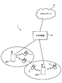
- FIG. 16 is an explanatory diagram of a system configuration of the wireless communication system according to the present embodiment.
- the radio communication system shown in FIG. 16 is a system that includes, for example, the LTE system or SUPER 3G.
- carrier aggregation (CA) in which a plurality of basic frequency blocks having the system band of the LTE system as a unit is integrated is used.
- this wireless communication system may be called IMT-Advanced or 4G.
- the radio communication system 1 includes radio base station devices (hereinafter referred to as “base station devices”) 20A and 20B at each transmission point (TP) and users communicating with the base station devices 20A and 20B.
- a terminal 10 is included.
- the base station devices 20 ⁇ / b> A and 20 ⁇ / b> B are connected to the higher station device 30, and the higher station device 30 is connected to the core network 40.
- the base station devices 20A and 20B are connected to each other by wired connection or wireless connection.
- the user terminal 10 can communicate with the base station apparatuses 20A and 20B that are transmission points.
- the upper station device 30 includes, for example, an access gateway device, a radio network controller (RNC), a mobility management entity (MME), and the like, but is not limited thereto.
- RNC radio network controller
- MME mobility management entity
- the user terminal 10 includes an existing terminal (Rel. 10 LTE) and a support terminal (for example, Rel. 11 LTE).
- a support terminal for example, Rel. 11 LTE.
- the user terminal 10 will be described as a user terminal unless otherwise specified. For convenience of explanation, it is assumed that the user terminal 10 performs wireless communication with the base station apparatuses 20A and 20B.
- OFDMA Orthogonal Frequency Division Multiple Access
- SC-FDMA Single Carrier-Frequency Division Multiple Access
- the wireless access method is not limited to this.
- OFDMA is a multi-carrier transmission scheme that performs communication by dividing a frequency band into a plurality of narrow frequency bands (subcarriers) and mapping data to each subcarrier.
- SC-FDMA is a single carrier transmission method that reduces interference between terminals by dividing a system band into bands each consisting of one or continuous resource blocks for each terminal, and a plurality of terminals using different bands. .
- the downlink communication channel includes PDSCH as a downlink data channel shared by the user terminals 10 and downlink L1 / L2 control channels (PDCCH, PCFICH, PHICH). Transmission data and higher control information are transmitted by the PDSCH. PDSCH and PUSCH scheduling information and the like are transmitted by the PDCCH. The number of OFDM symbols used for the PDCCH is transmitted by PCFICH (Physical Control Format Indicator Channel). HACH ACK / NACK for PUSCH is transmitted by PHICH (Physical Hybrid-ARQ Indicator Channel).
- PCFICH Physical Control Format Indicator Channel
- HACH ACK / NACK for PUSCH is transmitted by PHICH (Physical Hybrid-ARQ Indicator Channel).
- the uplink communication channel has PUSCH (Physical Uplink Shared Channel) as an uplink data channel shared by each user terminal 10 and PUCCH (Physical Uplink Control Channel) as an uplink control channel. Transmission data and higher control information are transmitted by this PUSCH. Also, downlink channel state information (CSI (including CQI and the like)), ACK / NACK, and the like are transmitted by PUCCH.
- PUSCH Physical Uplink Shared Channel
- PUCCH Physical Uplink Control Channel
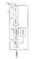
- the base station apparatus 20 includes a transmission / reception antenna 201, an amplifier unit 202, a transmission / reception unit (notification unit) 203, a baseband signal processing unit 204, a call processing unit 205, and a transmission path interface 206.
- Transmission data transmitted from the base station apparatus 20 to the user terminal 10 via the downlink is input from the higher station apparatus 30 to the baseband signal processing unit 204 via the transmission path interface 206.
- the downlink data channel signal is transmitted from the PDCP layer, RDL layer transmission processing such as transmission data division / combination, RLC (Radio Link Control) retransmission control, MAC (Medium Access), and so on.
- RDL layer transmission processing such as transmission data division / combination, RLC (Radio Link Control) retransmission control, MAC (Medium Access), and so on.
- Control retransmission control, for example, HARQ transmission processing, scheduling, transmission format selection, channel coding, Inverse Fast Fourier Transform (IFFT) processing, and precoding processing are performed.
- transmission processing such as channel coding and inverse fast Fourier transform is performed on the signal of the physical downlink control channel, which is the downlink control channel.
- the baseband signal processing unit 204 notifies the control information for each user terminal 10 to wirelessly communicate with the base station apparatus 20 to the user terminals 10 connected to the same transmission point through the broadcast channel.
- Information for communication at the transmission point includes, for example, system bandwidth in the uplink or downlink, and root sequence identification information (Root) for generating a random access preamble signal in PRACH (Physical Random Access Channel). (Sequence Index).
- the transmission / reception unit 203 converts the baseband signal output from the baseband signal processing unit 204 into a radio frequency band.
- the amplifier unit 202 amplifies the radio frequency signal subjected to frequency conversion and outputs the amplified signal to the transmission / reception antenna 201.
- a radio frequency signal received by the transmission / reception antenna 201 is amplified by the amplifier unit 202 and frequency-converted by the transmission / reception unit 203 to be a baseband signal. And is input to the baseband signal processing unit 204.
- the baseband signal processing unit 204 performs FFT processing, IDFT processing, error correction decoding, MAC retransmission control reception processing, RLC layer, PDCP layer reception processing on transmission data included in the baseband signal received in the uplink I do.
- the decoded signal is transferred to the higher station apparatus 30 via the transmission path interface 206.
- the call processing unit 205 performs call processing such as communication channel setting and release, state management of the base station apparatus 20, and management of radio resources.
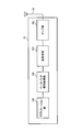
- the user terminal 10 includes a transmission / reception antenna 101, an amplifier unit 102, a transmission / reception unit (reception unit) 103, a baseband signal processing unit 104, and an application unit 105.
- a radio frequency signal received by the transmission / reception antenna 101 is amplified by the amplifier unit 102, frequency-converted by the transmission / reception unit 103, and converted into a baseband signal.
- the baseband signal is subjected to FFT processing, error correction decoding, retransmission control reception processing, and the like by the baseband signal processing unit 104.
- downlink transmission data is transferred to the application unit 105.
- the application unit 105 performs processing related to layers higher than the physical layer and the MAC layer. Also, broadcast information in the downlink data is also transferred to the application unit 105.
- uplink transmission data is input from the application unit 105 to the baseband signal processing unit 104.
- the baseband signal processing unit 104 performs mapping processing, retransmission control (HARQ) transmission processing, channel coding, DFT processing, and IFFT processing.
- the transmission / reception unit 103 converts the baseband signal output from the baseband signal processing unit 104 into a radio frequency band. Thereafter, the amplifier unit 102 amplifies the frequency-converted radio frequency signal and transmits it from the transmission / reception antenna 101.
- HARQ retransmission control
- each functional block in FIG. 19 mainly relates to the baseband signal processing unit 204 shown in FIG. Further, the functional block diagram of FIG. 19 is simplified for explaining the present invention, and is assumed to have a configuration normally provided in the baseband signal processing unit 204.
- the base station apparatus 20 includes a backhaul communication unit 401, a higher control information generation unit 402, a downlink transmission data generation unit 403, a downlink control information generation unit 404, an RS generation unit 405, and a downlink transmission data code.
- the base station apparatus 20 includes a downlink channel multiplexing unit 408, an IFFT unit 409, and a CP adding unit 410.
- the base station apparatus 20 includes a reception unit 411, a terminal capability determination unit 412, a reception quality determination unit 413, a CQI determination unit 414, a CoMP candidate cell determination unit 415, a table generation unit 416, a scheduler 417, It has.
- the backhaul communication unit 401 enables communication with other base stations through the backhaul.
- Upper control information generating section 402 generates higher control information transmitted to the user terminal by higher layer signaling (for example, RRC signaling), and outputs the generated higher control information to downlink transmission data encoding / modulating section 406 To do.
- the upper control information generation unit 402 includes control information including a rate matching attribute necessary for rate matching processing when only CoMP is applied, and information such as a cell index extended when CoMP and CA are applied. The control information including is generated.
- the upper control information generation unit 402 receives a rate matching table generated by a table generation unit 416 described later. Then, upper control information generating section 402 generates higher control information including this rate matching table, and outputs it to downlink transmission data encoding / modulating section 406.
- Downlink transmission data generation section 403 generates downlink transmission data and outputs the downlink transmission data to downlink transmission data encoding / modulation section 406. Note that user data as downlink transmission data is supplied from an upper layer.
- the downlink control information generation unit 404 constitutes a generation unit, and downlink control information (DCI) for controlling PDSCH using a DCI format (for example, DCI format 1A) containing DL ground. Is generated.
- DCI downlink control information
- the downlink control information generation section 404 When only CoMP is applied, the downlink control information generation section 404 generates DCI in which a rate matching pattern according to the CoMP transmission form is described in the CIF based on the registered contents of the rate matching table as shown in FIG. . Further, when CoMP and CA are applied, the downlink control information generation section 404 uses DCI in which a rate matching pattern according to the CoMP transmission form is described in the CIF based on the registered contents of the rate matching table as shown in FIG. Is generated. In this case, the CIF also includes CC index information in CA. At this time, the CIF added to the DCI is instructed by the scheduler 417 based on the registered contents of the rate matching table generated by the table generation unit 416 described later.
- the downlink transmission data coding / modulation section 406 performs channel coding and data modulation on the downlink transmission data and higher control information, and outputs the result to the downlink channel multiplexing section 408.
- the downlink control information coding / modulation section 407 performs channel coding and data modulation on the downlink control information and outputs the result to the downlink channel multiplexing section 408.
- the RS generation unit 405 may generate a desired signal measurement RS and an interference measurement RS in addition to generating an existing reference signal (CRS, CSI-RS, DM-RS). These RSs are output to the downlink channel multiplexing unit 408.
- the downlink channel multiplexing unit 408 generates a transmission signal by combining the downlink control information, the reference signal, the upper control information, and the downlink transmission data.
- the downlink channel multiplexing unit 408 outputs the generated transmission signal to the IFFT unit 409.
- the IFFT unit 409 performs inverse fast Fourier transform (Inverse Fast Fourier Transform) on the transmission signal, and converts the signal in the frequency domain into a signal in the time domain.
- the transmission signal after IFFT is output to CP adding section 410.
- CP adding section 410 adds CP (Cyclic Prefix) to the transmission signal after IFFT, and outputs the transmission signal after CP addition to amplifier section 202 shown in FIG.
- the receiving unit 411 receives a transmission signal from the user terminal, extracts terminal capability information (UE Capability), reception quality information, and channel quality information (CQI) from the received signal, and respectively receives the terminal capability determining unit 412, The data is output to reception quality determination section 413 and CQI determination section 414.
- UE Capability terminal capability information
- CQI channel quality information
- the terminal capability determination unit 412 determines the communication capability of the connected user terminal 10 based on the notified terminal capability of the user terminal 10. In particular, the terminal capability determination unit 412 determines whether the connected user terminal 10 is compatible with CoMP or CA based on the notified terminal capability. The terminal capability determination unit 412 outputs the determined terminal capability of the user terminal 10 to the CoMP candidate cell determination unit 415.
- the reception quality determination unit 413 determines the reception quality (for example, RSRP) of the measurement candidate cell based on the measurement report result.
- Reception quality determination section 413 outputs the determined reception quality to CoMP candidate cell determination section 415.
- the CQI determination unit 414 determines uplink / downlink reception quality.
- the CQI determination unit 414 outputs the determined uplink / downlink reception quality to the scheduler 417.
- the CoMP candidate cell determination unit 415 determines a CoMP candidate cell from the measurement candidate cells based on the terminal capability of the user terminal 10 and the reception quality of the measurement candidate cell.
- the CoMP candidate cell includes a CoMP set indicating a combination of individual coordinated cells serving as transmission points in CoMP transmission (DPS) and a plurality of cells jointly transmitted in CoMP transmission (JT).
- the CoMP candidate cell determination unit 415 outputs the determined CoMP candidate cell to the table generation unit 416.
- the table generation unit 416 generates a rate matching table based on the CoMP candidate cells. In this case, the table generation unit 416 generates the rate matching table shown in FIG. Then, the generated rate matching table is output to the backhaul communication unit 401, the upper control information generation unit 402, and the scheduler 417.
- the scheduler 417 determines a CoMP transmission cell that transmits a shared data channel (PDSCH) to the user terminal 10 from the CoMP candidate cells. At this time, the scheduler 417 also determines the CoMP transmission form. Also, the scheduler 417 determines whether the determined subframe of the CoMP transmission cell is an MBSFN subframe or a new carrier type subframe. For example, whether or not the MBSFN subframe is determined is determined based on the content of another Multi-cell / multicast MBSFN Entity. Based on the determination result and the registration information of the rate matching table, the scheduler 417 selects a rate matching pattern according to the CoMP transmission form. Then, the scheduler 417 instructs the downlink control information generating unit 404 to indicate CIF indicating the rate matching pattern.
- PDSCH shared data channel
- table matching section 416 generates a rate matching table in which the rate matching pattern corresponding to the CoMP transmission mode is associated with the bit information constituting CIF. .
- the generated rate matching table is notified to the user terminal 10 by RRC signaling.
- the scheduler 417 selects the CIF associated with the rate matching pattern corresponding to the CoMP transmission form.
- DCI including the CIF selected by the downlink control information generation unit 404 is generated and transmitted to the user terminal 10 on the downlink.
- the scheduler 417 receives a CoMP candidate cell from the CoMP candidate cell determination unit 415. Then, scheduling is performed from this CoMP candidate cell and CQI. Then, the scheduling result and the like are output to the table generation unit 416.
- the table generation unit 416 generates a rate matching table based on the scheduling result and the like. In this case, the table generation unit 416 generates the rate matching table shown in FIG. Then, the generated rate matching table is output to the backhaul communication unit 401, the upper control information generation unit 402, and the scheduler 417. In this case, since the rate matching table can be generated reflecting the scheduling result, the amount of information in the rate matching table can be reduced. Thereby, the information transmission amount at the time of notifying to the user terminal 10 can be reduced, and the throughput characteristic of the system can be improved.
- FIG. 20 mainly relates to the baseband signal processing unit 104 shown in FIG.
- the functional blocks shown in FIG. 20 are simplified to explain the present invention, and the baseband signal processing unit 104 normally has a configuration.
- the user terminal 10 includes a CP removing unit 301, an FFT unit 302, a downlink channel separating unit 303, a downlink control information receiving unit 304, a downlink transmission data receiving unit 305, an interference signal estimating unit 306, A channel estimation unit 307 and a CQI measurement unit 308 are provided.
- the transmission signal transmitted from the base station apparatus 20 is received by the transmission / reception antenna 101 shown in FIG. 18 and output to the CP removal unit 301.
- CP removing section 301 removes the CP from the received signal and outputs it to FFT section 302.
- the FFT unit 302 performs Fast Fourier Transform (FFT) on the signal after CP removal, and converts the signal in the time domain into a signal in the frequency domain.
- FFT section 302 outputs the signal converted into the frequency domain signal to downlink channel separation section 303.
- FFT Fast Fourier Transform
- the downlink channel separation unit 303 separates the downlink channel signal into downlink control information, downlink transmission data, and a reference signal (RS).
- the downlink channel separation unit 303 outputs downlink control information to the downlink control information reception unit 304, outputs downlink transmission data and higher-level control information to the downlink transmission data reception unit 305, and transmits an interference measurement RS to the interference signal estimation unit 306.
- the desired signal measurement RS is output to the channel estimation unit 307.
- the downlink control information receiving unit 304 demodulates the downlink control information (DCI), and outputs the demodulated DCI to the downlink transmission data receiving unit 305.
- Downlink transmission data receiving section 305 demodulates downlink transmission data using the demodulated DCI.
- the downlink control information receiving section 304 analyzes the rate matching pattern incorporated in the DCI CIF included in the PDCCH received from the specific cell using the rate matching table, and calculates the rate matching pattern from the CIF bit information. It functions as a determination unit that identifies The rate matching table is acquired from the upper control information included in the downlink transmission data.
- the downlink transmission data receiving unit 305 functions as a rate matching unit that performs rate matching based on the specified rate matching pattern.
- the downlink transmission data reception unit 305 outputs the upper control information included in the downlink transmission data to the interference signal estimation unit 306 and the channel estimation unit 307.
- the downlink transmission data receiving unit 305 acquires a rate matching table included in the higher control information and refers to it when executing rate matching.
- the interference signal estimation unit 306 estimates an interference signal using downlink reference signals such as CRS and CSI-RS.
- the interference signal estimation unit 306 can estimate the interference signal and average the measurement results in all resource blocks.
- the CQI measurement unit 308 is notified of the averaged interference signal estimation result.
- the channel estimation unit 307 specifies a desired signal measurement RE (CSI-RS resource) based on information such as transmission parameters included in the higher control information (or downlink control information), and uses the desired signal measurement RE to specify the desired signal. presume.
- CSI-RS resource CSI-RS resource
- the channel estimation unit 307 notifies the CQI measurement unit 308 of the channel estimation value.
- CQI measurement section 308 calculates a channel state (CQI) based on the interference estimation result notified from interference signal estimation section 306 and the channel estimation result notified from channel estimation section 307.
- the CQI calculated by the CQI measurement unit 308 is notified to the base station apparatus 20 as feedback information.
- the rate matching pattern corresponding to the CoMP transmission form receives from the base station apparatus 20 the rate matching table associated with the bit information constituting the CIF.
- PDCCH including CIF composed of bit information corresponding to the rate matching pattern is received.
- the user terminal 10 can identify the rate matching information (rate matching pattern) corresponding to the CoMP transmission form from the CIF defined in the DCI of the PDCCH. As a result, even when the CoMP transmission / reception technique is applied, information necessary for rate matching can be efficiently signaled.
Abstract
The present invention efficiently signals information necessary for rate matching even if a CoMP transmission/reception technology is applied. CoMP transmission that performs cooperative multipoint transmission to a user terminal (UE) with a plurality of wireless base station devices (eNB) as transmission points is scheduled; on the basis of a table in which a necessary rate matching pattern is mapped to bit data in accordance with the transmission form of CoMP transmission, downlink control information is generated incorporating a rate matching pattern in a physical downlink control channel; the physical downlink control channel is transmitted to the user terminal (UE); and a physical downlink shared data channel is transmitted; and the rate matching pattern incorporated in the downlink control information at the user terminal (UE) is identified on the basis of a table having the same contents as the wireless base station device (eNB).
Description
本発明は、次世代移動通信システムにおける無線通信システム、無線基地局装置、ユーザ端末及び通信制御方法に関する。
The present invention relates to a radio communication system, a radio base station apparatus, a user terminal, and a communication control method in a next generation mobile communication system.
UMTS(Universal Mobile Telecommunication System)ネットワークにおいては、周波数利用効率の向上、データレートの向上を目的として、HSDPA(High Speed Downlink Packet Access)やHSUPA(High Speed Uplink Packet Access)を採用することにより、W-CDMA(Wideband Code Division Multiple Access)をベースとしたシステムの特徴を最大限に引き出すことが行われている。このUMTSネットワークについては、さらなる高速データレート、低遅延などを目的としてロングタームエボリューション(LTE:Long Term Evolution)が検討されている(非特許文献1)。
In the UMTS (Universal Mobile Telecommunication System) network, HSDPA (High Speed Downlink Access Access) and HSUPA (High SpeckUsedWedPickUsedWidePac) are used to improve frequency utilization efficiency and data rate. A system based on CDMA (Wideband Code Division Multiple Access) is being maximally extracted. For this UMTS network, Long Term Evolution (LTE) has been studied for the purpose of further higher data rate, lower delay, and the like (Non-Patent Document 1).
第3世代のシステムは、概して5MHzの固定帯域を用いて、下り回線で最大2Mbps程度の伝送レートを実現できる。一方、LTEシステムでは、1.4MHz~20MHzの可変帯域を用いて、下り回線で最大300Mbps及び上り回線で最大75Mbps程度の伝送レートを実現できる。また、UMTSネットワークにおいては、さらなる広帯域化及び高速化を目的として、例えば、LTEアドバンスト又はLTEエンハンスメント(以下、「LTE-A」と記す)と呼ばれるLTEシステムの後継システムも検討されている。
The third generation system can achieve a maximum transmission rate of about 2 Mbps on the downlink using generally a fixed bandwidth of 5 MHz. On the other hand, in the LTE system, a transmission rate of about 300 Mbps at the maximum in the downlink and about 75 Mbps at the maximum in the uplink can be realized using a variable band of 1.4 MHz to 20 MHz. In the UMTS network, for the purpose of further increasing the bandwidth and speed, for example, a successor system of the LTE system called LTE advanced or LTE enhancement (hereinafter referred to as “LTE-A”) is also being studied.
LTEシステムに対して、更にシステム性能を向上させるための有望な技術の1つとして、セル間直交化が提案されている。例えば、LTE-Aシステムでは、上下リンクとも直交マルチアクセスによりセル内の直交化が実現されている。すなわち、下りリンクでは、周波数領域においてユーザ端末UE(User Equipment)間が直交化されている。セル間は、W-CDMAと同様、1セル周波数繰り返しによる干渉ランダム化が図られている。
Inter-cell orthogonalization has been proposed as one of promising technologies for further improving system performance for LTE systems. For example, in the LTE-A system, orthogonalization within a cell is realized by orthogonal multi-access for both uplink and downlink. That is, in the downlink, the user terminals UE (User Equipment) are orthogonalized in the frequency domain. As in W-CDMA, interference randomization is performed between cells by repeating one-cell frequency.
LTA-A(Rel.11)においては、セル間直交化を実現するための技術として、協調マルチポイント送受信(CoMP:Coordinated Multi-Point transmission/reception)技術の導入が検討されている。このCoMP送受信技術では、1つ或いは複数のユーザ端末UEに対して複数のセルが協調して送受信の信号処理を行う。このようなCoMP送受信技術の適用により、特にセル端に位置するユーザ端末UEのスループット特性の改善が期待される。
In LTA-A (Rel. 11), the introduction of coordinated multi-point transmission / reception (CoMP) technology as a technology for realizing orthogonalization between cells is being studied. In this CoMP transmission / reception technology, a plurality of cells perform transmission / reception signal processing in cooperation with one or a plurality of user terminals UE. Application of such CoMP transmission / reception technology is expected to improve the throughput characteristics of the user terminal UE located particularly at the cell edge.
CoMP送信には、1つのユーザ端末UEに対して複数のセルから同時に共有データチャネルを送信するジョイント送信(Joint Transmission)、ユーザ端末UEに対する送信セルをダイナミックに切り替えてデータを送信するDPS(Dynamic Point Selection)といった複数の送信形態がある。これらのJT又はDPSにおいて、協調してデータ送信を行う複数のセルは、CoMPセットと呼ばれる。
For CoMP transmission, joint transmission (Joint Transmission) that simultaneously transmits a shared data channel from a plurality of cells to one user terminal UE, and DPS (Dynamic Point) that dynamically switches the transmission cell to the user terminal UE and transmits data. There are a plurality of transmission forms such as (Selection). In these JT or DPS, a plurality of cells that perform data transmission in a coordinated manner are called CoMP sets.
CoMP送信されたデータを受信するユーザ端末UEは、受信データのビットレートを微調整するためにレートマッチングを行う必要がある。ここで、レートマッチングとは、トランスポートチャネルの復号化ビットに対して繰返し処理又は穴あけ削除(パンクチャリング)処理を行うことをいう。この場合において、CoMPセットを構成する各セルにおいては、物理下りリンク共有チャネル(PDSCH:Physical Downlink Shared Channel)が割り当てられるリソースエレメント(RE)の配置(より具体的には、数及び位置)が異なる。
The user terminal UE that receives the CoMP transmitted data needs to perform rate matching in order to finely adjust the bit rate of the received data. Here, rate matching refers to performing an iterative process or a puncturing process on the decoded bits of the transport channel. In this case, in each cell constituting the CoMP set, the arrangement (more specifically, the number and position) of the resource elements (RE) to which the physical downlink shared channel (PDSCH: Physical Downlink Shared Channel) is allocated is different. .
例えば、物理下りリンク制御チャネル(PDCCH:Physical Downlink Control Channel)は、セル毎に異なるシンボル数が設定され得る(サブフレームの先頭の1OFDMシンボル~3OFDMシンボル)。このため、PDCCHのシンボル数によって、PDSCHが割り当てられるREの数が増減する。また、CRS(Common Reference Signal)は、セルID(セルインデックス)に基づいて設定されるREの位置が変化する。このため、CoMPセットを構成するセルのセルIDに応じてPDSCHが割り当てられるREの位置が変化する。
For example, in the physical downlink control channel (PDCCH: Physical Downlink Control Channel), a different number of symbols can be set for each cell (the first OFDM symbol to the first 3 OFDM symbols of the subframe). For this reason, the number of REs to which the PDSCH is allocated increases or decreases depending on the number of PDCCH symbols. Moreover, the position of RE set based on cell ID (cell index) changes in CRS (Common Reference Signal). For this reason, the position of the RE to which the PDSCH is allocated changes according to the cell ID of the cells constituting the CoMP set.
ユーザ端末UEにおいて、適切にレートマッチングを行うためには、CoMPセットを構成するセル毎に、PDSCHが割り当てられるRE(PDSCHの割当て領域)を識別する必要がある。このため、無線基地局装置は、ユーザ端末UEに対して、セル毎のPDSCHの割当て領域を識別するための情報を含む、レートマッチングに必要な情報(レートマッチング情報)を通知することが好ましい。しかしながら、レートマッチング情報は、CoMP形態に対応して変化する。このため、ユーザ端末UEへ通知すべきレートマッチング情報は複雑化する。しかも、CoMP送信においては、異なる周波数帯域に対して別のCoMPセットを設定することも可能である。この場合、ユーザ端末UEへ通知すべきレートマッチング情報は、益々複雑化する。
In order to perform rate matching appropriately in the user terminal UE, it is necessary to identify an RE (PDSCH allocation area) to which the PDSCH is allocated for each cell constituting the CoMP set. For this reason, it is preferable that a radio base station apparatus notifies the information (rate matching information) required for rate matching including the information for identifying the allocation area | region of PDSCH for every cell with respect to the user terminal UE. However, the rate matching information changes corresponding to the CoMP form. For this reason, rate matching information to be notified to the user terminal UE is complicated. In addition, in CoMP transmission, it is possible to set different CoMP sets for different frequency bands. In this case, the rate matching information to be notified to the user terminal UE becomes more complicated.
本発明は、かかる実情に鑑みてなされたものであり、CoMP送受信技術を適用する場合でも、レートマッチングに必要な情報を効率的にシグナリングできる無線通信システム、無線基地局装置、ユーザ端末及び通信制御方法を提供することを目的とする。
The present invention has been made in view of such circumstances, and even when applying CoMP transmission / reception technology, a radio communication system, a radio base station apparatus, a user terminal, and communication control capable of efficiently signaling information necessary for rate matching It aims to provide a method.
本発明の無線通信システムは、それぞれがセルを形成する複数の無線基地局装置と、前記各無線基地局装置に対して無線リンクを介して接続するユーザ端末とを備えた無線通信システムであって、前記無線基地局装置は、前記ユーザ端末に対して他の無線基地局装置と共に送信ポイントとなって協調マルチポイント送信するCoMP送信をスケジューリングするスケジューラと、CoMP送信の送信形態に対応して必要なレートマッチングパターンがビットデータにマッピングされているテーブルに基づいて、物理下りリンク制御チャネルに前記レートマッチングパターンを組み込んだ下りリンク制御情報を生成する生成部と、前記物理下りリンク制御チャネルを送信すると共に物理下りリンク共有データチャネルを送信する送信部とを具備し、前記ユーザ端末は、前記物理下りリンク制御チャネルを受信すると共にCoMP送信する全ての無線基地局装置から前記物理下りリンク共有データチャネルを受信する受信部と、受信した前記物理下りリンク制御チャネルに含まれた前記下りリンク制御情報に組み込まれている前記レートマッチングパターンを、前記無線基地局装置と同一内容のテーブルに基づいて特定する判定部と、特定した前記レートマッチングパターンを用いて前記下りリンク共有データチャネルのレートマッチングを行うレートマッチング部とを具備することを特徴とする。
A radio communication system according to the present invention is a radio communication system including a plurality of radio base station apparatuses each forming a cell and a user terminal connected to each radio base station apparatus via a radio link. The radio base station apparatus is required to correspond to the scheduler that schedules CoMP transmission that performs coordinated multipoint transmission to the user terminal as a transmission point together with other radio base station apparatuses, and the transmission mode of CoMP transmission. Based on a table in which a rate matching pattern is mapped to bit data, a generation unit that generates downlink control information in which the rate matching pattern is incorporated in a physical downlink control channel, and transmits the physical downlink control channel A transmitter for transmitting the physical downlink shared data channel. The user terminal receives the physical downlink control channel and receives the physical downlink shared data channel from all the radio base station apparatuses that perform CoMP transmission and the received physical downlink control channel. A determination unit that identifies the rate matching pattern incorporated in the included downlink control information based on a table having the same contents as the radio base station device, and the downlink using the identified rate matching pattern And a rate matching unit that performs rate matching of the shared data channel.
本発明の無線基地局装置は、ユーザ端末が無線リンクを介して接続する無線基地局装置であって、前記ユーザ端末に対して他の無線基地局装置と共に送信ポイントとなって協調マルチポイント送信するCoMP送信をスケジューリングするスケジューラと、CoMP送信の送信形態に対応して必要なレートマッチングパターンがビットデータにマッピングされているテーブルに基づいて、物理下りリンク制御チャネルに前記レートマッチングパターンを組み込んだ下りリンク制御情報を生成する生成部と、前記物理下りリンク制御チャネルを送信すると共に物理下りリンク共有データチャネルを送信する送信部とを具備することを特徴とする。
The radio base station apparatus of the present invention is a radio base station apparatus to which a user terminal connects via a radio link, and performs coordinated multipoint transmission to the user terminal as a transmission point together with other radio base station apparatuses. Downlink in which the rate matching pattern is incorporated into a physical downlink control channel based on a scheduler that schedules CoMP transmission and a table in which a rate matching pattern necessary for the transmission form of CoMP transmission is mapped to bit data A generation unit that generates control information, and a transmission unit that transmits the physical downlink control channel and transmits the physical downlink shared data channel are provided.
本発明のユーザ端末は、それぞれがセルを形成する複数の無線基地局装置に対して無線リンクを介して接続するユーザ端末であって、前記無線基地局装置から物理下りリンク制御チャネルを受信すると共にCoMP送信する全ての前記無線基地局装置から物理下りリンク共有データチャネルを受信する受信部と、受信した前記物理下りリンク制御チャネルに含まれた下りリンク制御情報に組み込まれているレートマッチングパターンを、予め準備されたテーブルに基づいて特定する判定部と、特定した前記レートマッチングパターンを用いて前記下りリンク共有データチャネルのレートマッチングを行うレートマッチング部とを具備し、前記テーブルは、CoMP送信の送信形態に対応して必要なレートマッチングパターンがビットデータにマッピングされていることを特徴とする。
A user terminal according to the present invention is a user terminal that is connected to a plurality of radio base station apparatuses each forming a cell via a radio link, and receives a physical downlink control channel from the radio base station apparatus. A receiving unit that receives physical downlink shared data channels from all the radio base station devices that perform CoMP transmission, and a rate matching pattern that is incorporated in downlink control information included in the received physical downlink control channel, A determination unit that identifies based on a table prepared in advance; and a rate matching unit that performs rate matching of the downlink shared data channel using the identified rate matching pattern. The required rate matching pattern corresponding to the form is bit data Characterized in that it is mapped.
本発明の通信制御方法は、それぞれがセルを形成する複数の無線基地局装置と、前記各無線基地局装置に対して無線リンクを介して接続するユーザ端末とを備えた無線通信システムにおける通信制御方法であって、前記ユーザ端末に対して前記複数の無線基地局装置が送信ポイントとなって協調マルチポイント送信するCoMP送信をスケジューリングするステップと、CoMP送信の送信形態に対応して必要なレートマッチングパターンがビットデータにマッピングされているテーブルに基づいて、物理下りリンク制御チャネルに前記レートマッチングパターンを組み込んだ下りリンク制御情報を生成するステップと、前記物理下りリンク制御チャネルを送信すると共に物理下りリンク共有データチャネルを送信するステップと、前記ユーザ端末で前記下りリンク制御情報に組み込まれる前記レートマッチングパターンを、前記無線基地局装置と同一内容の前記テーブルに基づいて特定するステップとを具備することを特徴とする。
The communication control method of the present invention is a communication control in a radio communication system comprising a plurality of radio base station apparatuses each forming a cell and a user terminal connected to each radio base station apparatus via a radio link. A method for scheduling CoMP transmission in which the plurality of radio base station apparatuses serve as transmission points for the multi-point transmission to the user terminal, and a rate matching necessary for a transmission form of CoMP transmission Generating downlink control information in which the rate matching pattern is incorporated in a physical downlink control channel based on a table in which a pattern is mapped to bit data; and transmitting the physical downlink control channel and a physical downlink Transmitting a shared data channel; and The rate matching pattern incorporated in the downlink control information The terminal, characterized by comprising a step of identifying, based on said table having the same content as the radio base station apparatus.
本発明によれば、CoMP送受信技術を適用する場合でも、レートマッチングに必要な情報を効率的にシグナリングすることが可能となる。
According to the present invention, it is possible to efficiently signal information necessary for rate matching even when applying CoMP transmission / reception technology.
以下、本発明の実施の形態について添付図面を参照して詳細に説明する。
まず、図1を参照しながら、LTE-A(Rel.11)において導入が検討されているCoMP送受信技術について説明する。図1は、CoMP送受信(協調マルチポイント送受信)技術を説明するための図である。 Hereinafter, embodiments of the present invention will be described in detail with reference to the accompanying drawings.
First, a CoMP transmission / reception technique that has been studied for introduction in LTE-A (Rel. 11) will be described with reference to FIG. FIG. 1 is a diagram for explaining a CoMP transmission / reception (cooperative multipoint transmission / reception) technique.
図1Aは、CoMP送信の1つであるジョイント送信(以下、適宜「CoMP送信(JT)」という)の概念図である。図1Aに示すように、ジョイント送信では、1サブフレームにおいて、1つのユーザ端末UEに対して複数セルから同一の共有データチャネル(PDSCH)を同時送信する。例えば、ユーザ端末UEは、1サブフレーム内で、セル0、セル1及びセル2の全ての送信セルからPDSCHを受信する。この場合、ユーザ端末UEは、セル0、セル1及びセル2で共用するPDCCHに基づいて、セル0、セル1及びセル2からジョイント送信されたPDSCHを受信する。
FIG. 1A is a conceptual diagram of joint transmission (hereinafter referred to as “CoMP transmission (JT)” as appropriate), which is one of CoMP transmissions. As shown in FIG. 1A, in joint transmission, the same shared data channel (PDSCH) is simultaneously transmitted from a plurality of cells to one user terminal UE in one subframe. For example, the user terminal UE receives PDSCH from all transmission cells of cell 0, cell 1 and cell 2 in one subframe. In this case, the user terminal UE receives the PDSCH jointly transmitted from the cell 0, the cell 1, and the cell 2 based on the PDCCH shared by the cell 0, the cell 1, and the cell 2.
図1Bは、CoMP送信の1つであるDPS(以下、適宜「CoMP送信(DPS)」という)の概念図である。図1Bに示すように、DPSでは、1つのユーザ端末UEに対する送信セルをダイナミックに切り替えてPDSCHを送信する。この場合、ユーザ端末UEは、セル0、セル1及びセル2からそれぞれ送信されるPDCCHに基づいて、セル0、セル1及びセル2からそれぞれ送信されるPDSCHを受信する。
FIG. 1B is a conceptual diagram of DPS (hereinafter, referred to as “CoMP transmission (DPS)” as appropriate), which is one of CoMP transmissions. As shown in FIG. 1B, in DPS, the transmission cell for one user terminal UE is dynamically switched to transmit the PDSCH. In this case, the user terminal UE receives the PDSCH transmitted from the cell 0, the cell 1 and the cell 2 based on the PDCCH transmitted from the cell 0, the cell 1 and the cell 2, respectively.
これらのCoMP送受信技術は、セル端に存在するユーザ端末UEのスループットの改善に有効であることが確認されている。無線基地局装置eNBは、ユーザ端末UEから各セルの品質情報をフィードバックさせる。そして、無線基地局装置eNBは、セル毎の品質情報(例えば、RSRP(Reference Signal Received Power)、RSRQ(Reference Signal Received Quality)又は、SINR(Signal Interference plus Noise Ratio))の差を求める。
These CoMP transmission / reception techniques have been confirmed to be effective for improving the throughput of the user terminal UE existing at the cell edge. The radio base station apparatus eNB feeds back quality information of each cell from the user terminal UE. Then, the radio base station apparatus eNB obtains quality information for each cell (for example, RSRP (Reference Signal Received Power), RSRQ (Reference Signal Received Quality), or SINR (Signal Interference Plus) Noise Ratio Ratio).
セル間の品質情報の差が予め定めた閾値以下である場合(すなわち、セル間の品質差が小さい場合)、無線基地局装置eNBは、ユーザ端末UEがセル端に存在すると判断する。この場合、無線基地局装置eNBは、CoMP送信を適用する。一方、セル間の品質情報の差が閾値を超える場合(すなわち、セル間の品質差が大きい場合)、いずれかのセルを形成している無線基地局装置eNBに近いので、無線基地局装置eNBは、受信品質の高いセルの中央付近にユーザ端末UEが存在すると判断する。この場合は、CoMP送信を適用しなくても高い受信品質を維持できる。
When the difference in quality information between cells is equal to or less than a predetermined threshold (that is, when the quality difference between cells is small), the radio base station apparatus eNB determines that the user terminal UE exists at the cell edge. In this case, the radio base station apparatus eNB applies CoMP transmission. On the other hand, when the difference in quality information between cells exceeds a threshold value (that is, when the quality difference between cells is large), the radio base station apparatus eNB is close to the radio base station apparatus eNB forming any cell. Determines that the user terminal UE exists near the center of a cell with high reception quality. In this case, high reception quality can be maintained without applying CoMP transmission.
なお、CoMP送信が適用される場合、ユーザ端末UEは、複数のセル毎のチャネル状態情報を無線基地局装置eNB(サービングセルの無線基地局装置eNB)にフィードバックする。一方、CoMP送信が適用されない場合、ユーザ端末UEは、サービングセルのチャネル状態情報を無線基地局装置eNBにフィードバックする。
In addition, when CoMP transmission is applied, the user terminal UE feeds back channel state information for each of a plurality of cells to the radio base station apparatus eNB (the radio base station apparatus eNB of the serving cell). On the other hand, when CoMP transmission is not applied, the user terminal UE feeds back channel state information of the serving cell to the radio base station apparatus eNB.
上述したように、CoMP送信されたデータを受信するユーザ端末UEは、受信データに対してレートマッチングを行う。ここで、図2を参照しながら、CoMP送受信技術が適用される場合のレートマッチングの対象について説明する。図2Aにおいては、CoMPセットを構成する各セル(セル0~セル2)のサブフレームのフレーム構成の一例を示している。図2Bにおいては、図2Aに示すセル0及びセル1からジョイント送信される場合のレートマッチング対象を示している。なお、図2に示すサブフレームにおいては、横軸に時間を示し、縦軸に周波数を示している。図3においても同様である。
As described above, the user terminal UE that receives CoMP-transmitted data performs rate matching on the received data. Here, an object of rate matching when the CoMP transmission / reception technique is applied will be described with reference to FIG. FIG. 2A shows an example of a frame configuration of a subframe of each cell (cell 0 to cell 2) constituting the CoMP set. 2B shows a rate matching target when joint transmission is performed from cell 0 and cell 1 shown in FIG. 2A. In the subframe shown in FIG. 2, the horizontal axis indicates time, and the vertical axis indicates frequency. The same applies to FIG.
図2Aに示すように、セル0~セル2のサブフレームにおいては、PDCCHが割り当てられる領域(PDCCHの割当て領域)がそれぞれ異なる。図2Aにおいては、PDCCHの割当て領域として、セル0では第1OFDM(直交周波数分割多元接続)シンボルが割り当てられ、セル1では第1、第2OFDMシンボルが割り当てられ、セル2では第1~第3OFDMシンボルが割り当てられた場合について示している。また、セル0~セル2のサブフレームにおいては、セルIDに応じて異なるREにCRSが配置されている。PDSCHは、セル0~セル2のサブフレームのPDCCH及びCRSが配置されていないREに割り当てられる。すなわち、PDSCHの割当て領域は、CoMPセットを構成するセル毎に異なっている。
As shown in FIG. 2A, in the subframes of cell 0 to cell 2, the areas to which PDCCH is allocated (PDCCH allocation areas) are different. In FIG. 2A, the first OFDM (Orthogonal Frequency Division Multiple Access) symbol is assigned in cell 0, the first and second OFDM symbols are assigned in cell 1, and the first to third OFDM symbols are assigned in cell 2 as PDCCH allocation regions. It shows about the case where is assigned. In the subframes of cell 0 to cell 2, CRSs are arranged in different REs according to cell IDs. The PDSCH is assigned to REs in which the PDCCH and CRS of the subframes of the cell 0 to the cell 2 are not arranged. That is, the PDSCH allocation region is different for each cell constituting the CoMP set.
各セルからデータを受信する場合、ユーザ端末UEは、各セルのサブフレームにおいてPDSCHが割り当てられたREを対象としてレートマッチングを行う。例えば、セル0からデータを受信する場合、ユーザ端末UEは、PDCCHが割り当てられるRE(第1OFDMシンボルのRE)と、CRSが割り当てられるRE以外のREを対象としてレートマッチングを行う。なお、セル1、セル2からデータを受信する場合においても同様である。
When receiving data from each cell, the user terminal UE performs rate matching for the RE to which the PDSCH is assigned in the subframe of each cell. For example, when receiving data from cell 0, the user terminal UE performs rate matching for REs to which the PDCCH is assigned (RE of the first OFDM symbol) and REs other than the RE to which the CRS is assigned. The same applies when data is received from cell 1 and cell 2.
ここで、セル0及びセル1からユーザ端末UEにジョイント送信する場合のレートマッチング対象となるPDSCHについて考える。セル0及びセル1からジョイント送信される場合、図2Bに示すように、PDSCHは、セル0及びセル1のいずれのセルにおいても、PDCCH及びCRSが割り当てられていないREに割り当てられる。このため、ユーザ端末UEは、PDCCHが割り当てられるRE(第1OFDMシンボル及び第2OFDMシンボルのRE)と、CRSが割り当てられるRE以外のREを対象としてレートマッチングを行う。
Here, a PDSCH that is a rate matching target when joint transmission is performed from the cell 0 and the cell 1 to the user terminal UE will be considered. When joint transmission is performed from the cell 0 and the cell 1, as shown in FIG. 2B, the PDSCH is assigned to an RE to which no PDCCH and CRS are assigned in both the cell 0 and the cell 1. For this reason, the user terminal UE performs rate matching for REs to which the PDCCH is assigned (REs of the first OFDM symbol and the second OFDM symbol) and REs other than the RE to which the CRS is assigned.
ところで、LTE(Rel.9)においては、同報型配信を実現するベアラサービスであるMBMS(Multimedia Broadcast Multicast Service)が導入されている。このMBMSでは、MBSFN(MBMS Single Frequency Network)送信方式がサポートされている。このMBSFN送信方式は、ネットワークを構成する複数の無線基地局装置eNBが、同一信号を一斉同期送信することで、ユーザ端末UEが各無線基地局装置eNBから送信された信号をRF(Radio Freaquency)合成できる方式である。
By the way, in LTE (Rel. 9), MBMS (Multimedia Broadcast Multicast Service), which is a bearer service for realizing broadcast delivery, has been introduced. This MBMS supports an MBSFN (MBMS Single Frequency Network) transmission method. In this MBSFN transmission method, a plurality of radio base station apparatuses eNB configuring a network simultaneously transmits the same signal, whereby a user terminal UE transmits a signal transmitted from each radio base station apparatus eNB to RF (Radio Frequency). It is a method that can be synthesized.
また、Rel.11以降のLTEシステムにおいては、フレーム構成として、サブフレームにおいて既存のPDCCHの割当て領域を持たないキャリアタイプ(New carrier)が検討されている。このNew carrierタイプのサブフレームにおいては、CRSを割り当てず、全てのREにPDSCHを割り当てることが想定される。なお、このNew carrierタイプのサブフレームは、Additional carrierタイプのサブフレームと呼ぶこともできる。
Also, Rel. In the LTE system 11 or later, a carrier type (New carrier) that does not have an existing PDCCH allocation area in a subframe is considered as a frame configuration. In this New carrier type subframe, it is assumed that no CRS is allocated and PDSCH is allocated to all REs. Note that this New carrier type subframe can also be referred to as an Additive carrier type subframe.
ここで、図3を参照しながら、MBSFN又はNew carrierタイプが適用されるセルを含んでジョイント送信される場合のレートマッチングの対象について説明する。図3は、MBSFN又はNew carrierタイプのセルを含んでジョイント送信される場合のレートマッチング対象の説明図である。図3Aにおいては、MBSFNサブフレームのフレーム構成を示している。図3Bにおいては、New carrierタイプサブフレームのフレーム構成を示している。図3Cは、MBSFNのサブフレーム又はNew carrierタイプのセルを含んでジョイント送信された場合のレートマッチング対象となるPDSCHを示している。
Here, the target of rate matching in the case of joint transmission including cells to which MBSFN or New carrier type is applied will be described with reference to FIG. FIG. 3 is an explanatory diagram of a rate matching target when joint transmission is performed including an MBSFN or New carrier type cell. FIG. 3A shows a frame configuration of the MBSFN subframe. FIG. 3B shows a frame structure of a New carrier type subframe. FIG. 3C illustrates a PDSCH that is a rate matching target when joint transmission is performed including an MBSFN subframe or a new carrier type cell.
MBSFNサブフレームでは、図3Aに示すように、PDCCHの割当て領域として、サブフレームの先頭から最大2OFDMシンボルが定められている。図3Aにおいては、1OFDMシンボルがPDCCHの割当て領域として指定された場合について示している。また、MBSFNサブフレームでは、PDCCHの割当て領域以外のREがPDSCHの割当て領域として定められている。しかも、このPDSCHの割当て領域には、CRSが割り当てられることがない。このため、MBSFNサブフレームでは、第2OFDMシンボル又は第3OFDMシンボル以降の全てのREにPDSCHを割り当てることができる。
In the MBSFN subframe, as shown in FIG. 3A, a maximum of 2 OFDM symbols are defined from the top of the subframe as the PDCCH allocation area. FIG. 3A shows a case where one OFDM symbol is designated as a PDCCH allocation area. In the MBSFN subframe, an RE other than the PDCCH allocation area is defined as the PDSCH allocation area. In addition, no CRS is assigned to the PDSCH allocation area. For this reason, in the MBSFN subframe, the PDSCH can be assigned to all REs after the second OFDM symbol or the third OFDM symbol.
なお、MBSFNサブフレームは、無線フレームを構成するサブフレーム#0~#9のうち、サブフレーム#0、#4、#5及び#9を除くサブフレームに選択的に設定される。すなわち、無線基地局装置eNBは、サブフレーム#1~#3、#6~#8に選択的にMBSFNサブフレームを設定できる。
The MBSFN subframe is selectively set to subframes other than subframes # 0, # 4, # 5, and # 9 among subframes # 0 to # 9 constituting the radio frame. That is, the radio base station apparatus eNB can selectively set MBSFN subframes in subframes # 1 to # 3 and # 6 to # 8.
一方、New carrierタイプサブフレームでは、図3Bに示すように、PDCCHの割当て領域が設けられず、CRSが割り当てられないことが想定される。このため、New carrierタイプサブフレームでは、サブフレームに含まれる全てのREにPDSCHを割り当てることができる。
On the other hand, in the New carrier type subframe, as shown in FIG. 3B, it is assumed that no PDCCH allocation area is provided and no CRS is allocated. For this reason, in the New carrier type subframe, PDSCH can be allocated to all REs included in the subframe.
ここで、これらのMBSFNサブフレーム又はNew carrierタイプサブフレームがセル2に設定されたものと仮定する。そして、このセル2及び図2に示すセル1からユーザ端末UEにジョイント送信する場合のレートマッチング対象となるPDSCHについて説明する。セル1及びセル2からジョイント送信される場合、図3Cに示すように、PDSCHは、セル1及びセル2のいずれのセルにおいても、PDCCH及びCRSが割り当てられていないREに割り当てられる。この場合、セル2のMBSFNサブフレーム及びNew carrierタイプサブフレームには、2OFDMシンボル以降のREにPDCCH及びCRSが割り当てられていない。このため、セル1のサブフレームでPDSCHが割り当てられたREがレートマッチングの対象とされる。
Here, it is assumed that these MBSFN subframes or New carrier type subframes are set in the cell 2. And PDSCH used as the rate matching object in the case of carrying out joint transmission from this cell 2 and the cell 1 shown in FIG. 2 to the user terminal UE is demonstrated. When joint transmission is performed from the cell 1 and the cell 2, as shown in FIG. 3C, the PDSCH is assigned to an RE to which no PDCCH and CRS are assigned in both the cell 1 and the cell 2. In this case, the PDCCH and CRS are not allocated to REs after 2 OFDM symbols in the MBSFN subframe and the new carrier type subframe of cell 2. For this reason, the RE to which the PDSCH is assigned in the subframe of cell 1 is the target of rate matching.
ところで、LTE-A(Rel.10)においては、周波数帯域が異なる複数のコンポーネントキャリア(CC:Component Carrier)を束ねて帯域拡張するための技術として、キャリアアグリゲーション(CA:Carrier Aggrigation)が採用されている。また、LTE-A(Rel.10)においては、CAによって複数のCCが用いられる場合、複数のCC(1つのプライマリセル+最大4つのセカンダリセル)のPDSCHに対して、1プライマリセルのPDCCHからスケジューリングを行うクロスキャリアスケジューリングが採用されている。なお、PDCCHによって送信される下りリンク制御情報の詳細は、DCI(Downlink Control Information)フォーマットとして定められている。
By the way, in LTE-A (Rel. 10), carrier aggregation (CA: Carrier Aggregation) is adopted as a technology for bundling a plurality of component carriers (CC: Component Carrier) having different frequency bands to expand the band. Yes. Also, in LTE-A (Rel. 10), when a plurality of CCs are used by CA, the PDCCH of one primary cell is different from the PDSCH of a plurality of CCs (one primary cell + maximum four secondary cells). Cross-carrier scheduling that performs scheduling is employed. The details of the downlink control information transmitted by the PDCCH are defined as a DCI (Downlink Control Information) format.
クロスキャリアスケジューリングが適用される場合、プライマリセルにおいてPDCCHの割当て領域(先頭OFDMシンボルから最大3OFDMシンボルまでの無線リソース)には、セカンダリセルのPDCCHのDCIが割り当てられる。この場合、どのセルのPDSCHを受信するためのPDCCHであるかを識別可能にするため、DCIには、セルインデックスを示すCIF(Cell Index Field)が規定されている。
When cross-carrier scheduling is applied, the DCI of the secondary cell PDCCH is allocated to the PDCCH allocation region (radio resources from the first OFDM symbol to a maximum of 3 OFDM symbols) in the primary cell. In this case, CIF (Cell Index Field) indicating a cell index is defined in DCI so that it can be identified which cell is the PDCCH for receiving the PDSCH.
ここで、図4Aに示すシステム構成(HetNeT環境)においてCAを適用する場合について考える。図4Aに示す無線通信システムには、広範囲のカバレッジエリアを有するマクロセル(セル0)と、マクロセル(セル0)のカバレッジエリア内に局所的なカバレッジエリアを有するピコセル(セル1)とが配置されている。なお、ピコセル(セル1)は、マクロセル(セル0)よりも送信電力が小さいので、小電力セルと呼ぶこともできる。ここでは、図4Bに示すように、マクロセル(セル0)に周波数帯域1が割り当てられ、ピコセル(セル1)に周波数帯域1とは異なる周波数帯域2が割り当てられるものとする。
Here, a case where CA is applied in the system configuration (HetNeT environment) shown in FIG. 4A will be considered. In the wireless communication system shown in FIG. 4A, a macro cell (cell 0) having a wide coverage area and a pico cell (cell 1) having a local coverage area in the coverage area of the macro cell (cell 0) are arranged. Yes. Note that the pico cell (cell 1) has a lower transmission power than the macro cell (cell 0), and can also be referred to as a low power cell. Here, as shown in FIG. 4B, frequency band 1 is assigned to the macro cell (cell 0), and frequency band 2 different from frequency band 1 is assigned to the pico cell (cell 1).
図4Aに示すシステム構成において、ユーザ端末UEは、まず、通信(RRC Connection)を確立するために、プライマリセル(Pcell)における無線基地局装置eNBへ自らの端末能力(UE Capability)を通知する。プライマリセルの無線基地局装置eNBは、通知された端末能力に基づいて、接続するユーザ端末UEの通信能力を把握する。ここで、ユーザ端末UEがCAに対応しており、複数のCCを用いて通信を行う場合には、無線基地局装置eNBは、以下の5つの情報を含む制御情報をRRC(Radio Resource Control)シグナリングで通知する。
・セカンダリセル(Scell)インデックス
・物理セルID及び下りリンクキャリア周波数
・CRSポート番号
・MBSFNサブフレーム構成及びサブフレームオフセット
・PDSCHスタートシンボル In the system configuration illustrated in FIG. 4A, first, the user terminal UE notifies its own terminal capability (UE Capability) to the radio base station apparatus eNB in the primary cell (Pcell) in order to establish communication (RRC Connection). The radio base station apparatus eNB of the primary cell grasps the communication capability of the connected user terminal UE based on the notified terminal capability. Here, when the user terminal UE supports CA and performs communication using a plurality of CCs, the radio base station apparatus eNB transmits control information including the following five pieces of information to RRC (Radio Resource Control). Notify by signaling.
Secondary cell (Scell) index Physical cell ID and downlink carrier frequency CRS port number MBSFN subframe configuration and subframe offset PDSCH start symbol
複数セル(セル0、セル1)のPDSCHに対して1つのセル(セル0)からスケジューリングを行う場合(クロスキャリアスケジューリング)、図5Aに示すように、各セルから送信されるPDSCHに対するPDCCH(DCI)を、プライマリセルとなるセル0のPDCCH用リソースを用いて送信することができる。
When scheduling is performed from one cell (cell 0) for the PDSCH of multiple cells (cell 0, cell 1) (cross-carrier scheduling), as shown in FIG. 5A, PDCCH (DCI) for PDSCH transmitted from each cell ) Can be transmitted using the PDCCH resource of cell 0 serving as the primary cell.
クロスキャリアスケジューリングにおいては、プライマリセルのPDCCH用リソースに集約されて送信される複数セルのPDCCH(DCI)が、どのセルのPDCCHであるかを識別する必要がある。そこで、PDCCHが対応するセルを識別するためのCIFが、各セルのPDCCHのDCIに付加されている。これにより、ユーザ端末UEは、CIFを構成するビット情報に基づいて、PDCCHが対応するセルを識別することができる。
In cross carrier scheduling, it is necessary to identify which cell's PDCCH is the PDCCH (DCI) of a plurality of cells that are aggregated and transmitted in the PDCCH resources of the primary cell. Therefore, CIF for identifying the cell to which the PDCCH corresponds is added to the DCI of the PDCCH of each cell. Thereby, the user terminal UE can identify the cell to which the PDCCH corresponds based on the bit information constituting the CIF.
すなわち、無線基地局装置eNBとユーザ端末UEとで、図5Cに示すような共通のCIFテーブルを保持しておき、無線基地局装置eNBから通知されるCIFのビット情報に基づいてPDCCHのセルを特定することができる。図5Bは、PDCCHに含まれるDCIフォーマットの概念図であり、CAにおけるセルを示すビットデータがCIFに記述された様子を示している。なお、CIFには、図5に示すように、3ビットが割り当てられている。
That is, the radio base station apparatus eNB and the user terminal UE hold a common CIF table as shown in FIG. 5C, and change the PDCCH cell based on the CIF bit information notified from the radio base station apparatus eNB. Can be identified. FIG. 5B is a conceptual diagram of the DCI format included in the PDCCH, and shows a state in which bit data indicating a cell in CA is described in the CIF. As shown in FIG. 5, 3 bits are allocated to the CIF.
例えば、図5Cに示すCIFテーブルによれば、受信したPDCCHのDCIに含まれるCIFにビット情報(000)が指定されている場合、ユーザ端末UEは、そのPDCCHが、セル0のPDSCHを受信するためのPDCCHであると認識できる。一方、受信したPDCCHのDCIに含まれるCIFにビット情報(001)が指定されている場合、ユーザ端末UEは、そのPDCCHが、セル1のPDSCHを受信するためのPDCCHであると認識できる。
For example, according to the CIF table shown in FIG. 5C, when bit information (000) is specified in the CIF included in the DCI of the received PDCCH, the user terminal UE receives the PDSCH of cell 0 as the PDCCH. Can be recognized as a PDCCH. On the other hand, when bit information (001) is specified in the CIF included in the DCI of the received PDCCH, the user terminal UE can recognize that the PDCCH is a PDCCH for receiving the PDSCH of the cell 1.
上述したように、CoMP送受信技術が適用される場合、ユーザ端末UEは、受信データのビットレートを微調整するためにレートマッチングを行う必要がある。このため、無線基地局装置eNBは、レートマッチングに必要な情報(レートマッチング情報)を通知することが好ましい。しかしながら、ユーザ端末UEに対するレートマッチング情報の通知に関しては定められていない。本発明者等は、CoMP送受信技術が適用される場合においても、PDCCHに規定されるDCIを使用することでレートマッチング情報をユーザ端末UEに通知できることに着目し、本発明に至った。
As described above, when the CoMP transmission / reception technique is applied, the user terminal UE needs to perform rate matching in order to finely adjust the bit rate of received data. For this reason, it is preferable that the radio base station apparatus eNB notifies information required for rate matching (rate matching information). However, the notification of rate matching information to the user terminal UE is not defined. The present inventors have focused on the fact that rate matching information can be notified to the user terminal UE by using DCI defined in PDCCH even when CoMP transmission / reception technology is applied, and have reached the present invention.
すなわち、本発明の骨子は、CoMP送受信技術が適用される場合、無線基地局装置eNBにおいて、CoMP送信形態に対応して必要なレートマッチングパターンがビットデータにマッピングされているレートマッチングテーブルに基づいて、PDCCHにレートマッチングパターンを組み込んだDCIを生成し、このPDCCHを送信すると共にPDSCHを送信し、ユーザ端末UEでDCIに組み込まれているレートマッチングパターンを、無線基地局装置eNBと同一内容のレートマッチングテーブルに基づいて特定するものである。
That is, the gist of the present invention is based on a rate matching table in which a rate matching pattern necessary for the CoMP transmission mode is mapped to bit data in the radio base station apparatus eNB when CoMP transmission / reception technology is applied. , Generating DCI including a rate matching pattern in PDCCH, transmitting this PDCCH and transmitting PDSCH, and setting the rate matching pattern embedded in DCI in user terminal UE to the same content as radio base station apparatus eNB It is specified based on the matching table.
本発明によれば、CoMP送信形態に対応するレートマッチングパターンを組み込んだDCIを含むPDCCHがユーザ端末UEに送信される。そして、DCIに組み込まれたレートマッチングパターンが、無線基地局装置eNBと同一内容のレートマッチングテーブルに基づいて特定される。このため、CoMP送受信技術を適用する場合でも、レートマッチングに必要な情報を効率的にシグナリングすることが可能となる。
According to the present invention, the PDCCH including DCI incorporating a rate matching pattern corresponding to the CoMP transmission mode is transmitted to the user terminal UE. And the rate matching pattern incorporated in DCI is specified based on the rate matching table of the same content as the radio base station apparatus eNB. For this reason, even when CoMP transmission / reception technology is applied, it is possible to efficiently signal information necessary for rate matching.
以下、本実施の形態に係る無線通信システムについて具体的に説明する。図1に示すシステム構成において、ユーザ端末UEは、まず、制御チャネル(RRC Connection)を確立するために、プライマリセル(サービングセル、セル0)における無線基地局装置eNBへ自らの端末能力(UE Capability)を通知する。また、ユーザ端末UEは、生成したチャネル品質情報(CQI:Channel Quality Indicator)を無線基地局装置eNBにフィードバックする。
Hereinafter, the radio communication system according to the present embodiment will be specifically described. In the system configuration shown in FIG. 1, first, the user terminal UE establishes its own terminal capability (UE Capability) to the radio base station apparatus eNB in the primary cell (serving cell, cell 0) in order to establish a control channel (RRC Connection). To be notified. Also, the user terminal UE feeds back the generated channel quality information (CQI: Channel Quality Indicator) to the radio base station apparatus eNB.
無線基地局装置eNBは、通知された端末能力に基づいて、接続するユーザ端末UEの通信能力を把握する。ユーザ端末UEがCoMP送受信に対応している場合には、無線基地局装置eNBは、ユーザ端末UEにメジャメント候補セルをRRC(Radio Resource Control)プロトコルの制御信号によって通知する。図1に示すシステム構成の場合、メジャメント候補セルとしてセル0~セル2の3つのセルが通知される。ユーザ端末UEは、各メジャメント候補セルのRSRPなどを測定し、無線基地局装置eNBに対して、メジャメントレポート(測定報告)結果を、ハイヤレイヤシグナリング(例えば、RRCシグナリング)で報告する。
The radio base station apparatus eNB grasps the communication capability of the connected user terminal UE based on the notified terminal capability. When the user terminal UE is compatible with CoMP transmission / reception, the radio base station apparatus eNB notifies the user terminal UE of a measurement candidate cell using a control signal of an RRC (Radio Resource Control) protocol. In the case of the system configuration shown in FIG. 1, three cells of cell 0 to cell 2 are notified as measurement candidate cells. The user terminal UE measures RSRP and the like of each measurement candidate cell, and reports a measurement report (measurement report) result to the radio base station apparatus eNB by higher layer signaling (for example, RRC signaling).
無線基地局装置eNBは、メジャメントレポート結果に基づいて、メジャメント候補セルの中からCoMP候補セルを決定する。このCoMP候補セルには、CoMP送信(DPS)において送信ポイント(TP:Transmittion Point)となる個々の協調セル、並びに、CoMPのジョイント送信(JT)において送信ポイント(TP)となる複数セルの組み合わせを示すCoMPセットが含まれる。そして、無線基地局装置eNBは、CoMP候補セルにおける個々の協調セル(サービングセルを含む)及びCoMPセットに対応するレートマッチング情報を、CIFを構成するビット情報に関連付けたレートマッチングテーブルを生成する。
The radio base station apparatus eNB determines a CoMP candidate cell from the measurement candidate cells based on the measurement report result. In this CoMP candidate cell, there is a combination of individual cooperative cells that become transmission points (TP) in CoMP transmission (DPS) and multiple cells that become transmission points (TP) in joint transmission (JT) of CoMP. The indicated CoMP set is included. Then, the radio base station apparatus eNB generates a rate matching table in which the rate matching information corresponding to each cooperative cell (including the serving cell) and the CoMP set in the CoMP candidate cell is associated with the bit information constituting the CIF.
このレートマッチングテーブルにおいては、レートマッチング情報がレートマッチングパターンとして記述される。なお、このレートマッチングテーブルは、例えば、RRCシグナリングによって、ユーザ端末UEにシグナリングされる。これにより、無線基地局装置eNBとユーザ端末UEとの間でレートマッチングテーブルが共有される。なお、無線基地局装置eNBからユーザ端末UEへのシグナリングについては、RRCシグナリングに限定されない。例えば、報知信号(Physical Broadcast Channel)を用いて送信されるMIB(Master Information Block)、若しくはデータチャネルに多重されるSIB(System Information Block)で送られてもよいし、MAC(Medium Access Control)信号で送ってもよい。また、PDCCHを用いて送信してもよい。
In this rate matching table, rate matching information is described as a rate matching pattern. The rate matching table is signaled to the user terminal UE by RRC signaling, for example. Thereby, a rate matching table is shared between the radio base station apparatus eNB and the user terminal UE. Note that the signaling from the radio base station apparatus eNB to the user terminal UE is not limited to RRC signaling. For example, it may be sent by MIB (Master Information Block) transmitted using a broadcast signal (Physical Broadcast Channel), SIB (System Information Block) multiplexed on the data channel, or MAC (Medium Access Control) signal. You may send it by Moreover, you may transmit using PDCCH.
ここで、CoMP候補セル(セル0~セル2)が3つの場合のレートマッチングテーブルの一例について説明する。図6は、CoMP候補セルが3つの場合のレートマッチングテーブルの一例を示す図である。図6に示すレートマッチングテーブルにおいては、CIFを構成するビット情報に関連付けて、レートマッチング情報としてのレートマッチングパターン及びCoMP送信形態が登録されている。なお、CoMP送信形態においては、ジョイント送信が選択される場合にMBSFNサブフレーム又はNew carrierタイプサブフレームを用いてPDSCHを送信する送信ポイント(TP)を括弧内に示している。
Here, an example of the rate matching table when there are three CoMP candidate cells (cell 0 to cell 2) will be described. FIG. 6 is a diagram illustrating an example of a rate matching table when there are three CoMP candidate cells. In the rate matching table shown in FIG. 6, a rate matching pattern and a CoMP transmission form as rate matching information are registered in association with bit information constituting the CIF. In the CoMP transmission mode, when joint transmission is selected, a transmission point (TP) for transmitting the PDSCH using an MBSFN subframe or a new carrier type subframe is shown in parentheses.
図6に示すレートマッチングパターン(以下、適宜「パターン」と略す)について、図2及び図3を参照しながら説明する。なお、ここでは、CoMP候補セルであるセル0~セル2のサブフレームが図2に示すフレーム構成を有するものとする。パターン“TP0”は、図2に示すセル0のPDSCHの割当て領域をレートマッチング対象とするパターンである。同様に、パターン“TP1”、“TP2”は、それぞれ図2に示すセル1、セル2のPDSCHの割当て領域をレートマッチング対象とするパターンである。
The rate matching pattern shown in FIG. 6 (hereinafter, abbreviated as “pattern” as appropriate) will be described with reference to FIGS. Here, it is assumed that the subframes of cells 0 to 2 which are CoMP candidate cells have the frame configuration shown in FIG. The pattern “TP0” is a pattern in which the PDSCH allocation area of the cell 0 shown in FIG. Similarly, patterns “TP1” and “TP2” are patterns for which the PDSCH allocation areas of cell 1 and cell 2 shown in FIG.
また、パターン“TP0&TP1”は、図2Bに示すPDSCHの割当て領域をレートマッチング対象とするパターンである。すなわち、セル0及びセル1のいずれのセルにおいても、PDCCH及びCRSが割り当てられていないリソースがレートマッチング対象とされる。同様に、パターン“TP0&TP2”は、セル0及びセル2のいずれのセルにおいても、PDCCH及びCRSが割り当てられていないリソースをレートマッチング対象とするパターンである。パターン“TP1&TP2”は、セル1及びセル2のいずれのセルにおいても、PDCCH及びCRSが割り当てられていないリソースをレートマッチング対象とするパターンである。
Further, the pattern “TP0 & TP1” is a pattern for subjecting the PDSCH allocation area shown in FIG. 2B to rate matching. That is, in both the cell 0 and the cell 1, resources to which PDCCH and CRS are not assigned are targeted for rate matching. Similarly, the pattern “TP0 & TP2” is a pattern in which resources to which no PDCCH and CRS are allocated are targeted for rate matching in both the cell 0 and the cell 2. The pattern “TP1 & TP2” is a pattern in which resources to which no PDCCH and CRS are allocated are targeted for rate matching in both the cell 1 and the cell 2.
さらに、パターン“TP0&TP1&TP2”は、セル0、セル1及びセル2のいずれのセルにおいても、PDCCH及びCRSが割り当てられていないリソースをレートマッチング対象とするパターンである。パターン“Non-CRS”は、図3A又は図3Bに示すPDSCHの割当て領域をレートマッチング対象とするパターンである。すなわち、MBSFN又はNew carrierタイプのいずれのセルにおいても、PDCCHが割り当てられていないリソースがレートマッチング対象とされる。
Furthermore, the pattern “TP0 & TP1 & TP2” is a pattern in which resources to which no PDCCH and CRS are allocated are targeted for rate matching in any of the cells 0, 1 and 2. The pattern “Non-CRS” is a pattern for which the PDSCH allocation area shown in FIG. 3A or FIG. 3B is a rate matching target. That is, in any cell of MBSFN or New carrier type, a resource to which no PDCCH is assigned is a rate matching target.
図6に示すレートマッチングテーブルにおいては、パターン“TP0”、“TP1”及び“TP2”がCIFを構成するビット情報(000)、(001)及び(010)に関連付けられている。また、パターン“TP0&TP1”、“TP0&TP2”及び“TP1&TP2”がCIFを構成するビット情報(011)、(100)及び(101)に関連付けられている。さらに、パターン“TP0&TP1&TP2”及び“Non-CRS”がCIFを構成するビット情報(110)及び(111)に関連付けられている。
In the rate matching table shown in FIG. 6, the patterns “TP0”, “TP1”, and “TP2” are associated with the bit information (000), (001), and (010) constituting the CIF. Further, the patterns “TP0 & TP1”, “TP0 & TP2” and “TP1 & TP2” are associated with the bit information (011), (100) and (101) constituting the CIF. Further, the patterns “TP0 & TP1 & TP2” and “Non-CRS” are associated with the bit information (110) and (111) constituting the CIF.
パターン“TP0”は、CoMP送信(DPS)が適用される場合において、セル0(TP0)のみからPDSCHを送信する場合に選択される。一方、CoMP送信(JT)が適用される場合において、パターン“TP0”は、セル0(TP0)及びセル1(TP1)からPDSCHから送信される場合であって、セル1(TP1)からMBSFNサブフレーム又はNew carrierタイプサブフレームが送信される場合に選択される。同様に、パターン“TP0”は、セル0(TP0)及びセル2(TP2)からPDSCHから送信される場合であって、セル2(TP2)からMBSFNサブフレーム又はNew carrierタイプサブフレームが送信される場合に選択される。さらに、パターン“TP0”は、セル0(TP0)、セル1(TP1)及びセル2(TP2)からPDSCHから送信される場合であって、セル1(TP1)及びセル2(TP2)からMBSFNサブフレーム又はNew carrierタイプサブフレームが送信される場合に選択される。パターン“TP1”、“TP2”についても同様である。
The pattern “TP0” is selected when the PDSCH is transmitted only from the cell 0 (TP0) when CoMP transmission (DPS) is applied. On the other hand, in the case where CoMP transmission (JT) is applied, the pattern “TP0” is transmitted from the PDSCH from the cell 0 (TP0) and the cell 1 (TP1), and from the cell 1 (TP1) to the MBSFN sub. This is selected when a frame or New carrier type subframe is transmitted. Similarly, the pattern “TP0” is transmitted from the PDSCH from the cell 0 (TP0) and the cell 2 (TP2), and an MBSFN subframe or a new carrier type subframe is transmitted from the cell 2 (TP2). Selected when. Further, the pattern “TP0” is transmitted from the PDSCH from the cell 0 (TP0), the cell 1 (TP1), and the cell 2 (TP2), and is transmitted from the cell 1 (TP1) and the cell 2 (TP2) to the MBSFN sub. This is selected when a frame or New carrier type subframe is transmitted. The same applies to the patterns “TP1” and “TP2”.
パターン“TP0&TP1”は、CoMP送信(JT)が適用される場合において、セル0(TP0)及びセル1(TP1)からPDSCHから送信される場合に選択される。また、パターン“TP0&TP1”は、CoMP送信(JT)が適用される場合において、セル0(TP0)、セル1(TP1)及びセル2(TP2)からPDSCHが送信される場合であって、セル2(TP2)からMBSFNサブフレーム又はNew carrierタイプサブフレームが送信される場合に選択される。一方、CoMP送信(DPS)が適用される場合において、パターン“TP0&TP1”は、セル1(TP1)のCRSによる干渉を除去しながら、セル0(TP0)からPDSCHが送信される場合に選択される。これとは逆に、パターン“TP0&TP1”は、セル0(TP0)のCRSによる干渉を除去しながら、セル1(TP1)からPDSCHが送信される場合に選択される。パターン“TP0&TP2”、“TP1&TP2”についても同様である。
The pattern “TP0 & TP1” is selected when transmitting from PDSCH from cell 0 (TP0) and cell 1 (TP1) when CoMP transmission (JT) is applied. The pattern “TP0 & TP1” is a case where PDSCH is transmitted from cell 0 (TP0), cell 1 (TP1) and cell 2 (TP2) when CoMP transmission (JT) is applied. This is selected when an MBSFN subframe or a new carrier type subframe is transmitted from (TP2). On the other hand, in the case where CoMP transmission (DPS) is applied, the pattern “TP0 & TP1” is selected when PDSCH is transmitted from cell 0 (TP0) while removing interference due to CRS of cell 1 (TP1). . On the contrary, the pattern “TP0 & TP1” is selected when the PDSCH is transmitted from the cell 1 (TP1) while removing the interference due to the CRS of the cell 0 (TP0). The same applies to the patterns “TP0 & TP2” and “TP1 & TP2”.
パターン“TP0&TP1&TP2”は、CoMP送信(DPS)が適用される場合において、セル1(TP1)及びセル2(TP2)のCRSによる干渉を除去しながら、セル0(TP0)からPDSCHが送信される場合に選択される。同様に、パターン“TP0&TP1&TP2”は、セル0(TP0)及びセル2(TP2)のCRSによる干渉を除去しながら、セル1(TP1)からPDSCHが送信される場合、或いは、セル0(TP0)及びセル1(TP1)のCRSによる干渉を除去しながら、セル2(TP2)からPDSCHが送信される場合に選択される。
The pattern “TP0 & TP1 & TP2” is a case where PDSCH is transmitted from the cell 0 (TP0) while removing interference due to CRS of the cell 1 (TP1) and the cell 2 (TP2) when CoMP transmission (DPS) is applied. Selected. Similarly, the pattern “TP0 & TP1 & TP2” is obtained when the PDSCH is transmitted from the cell 1 (TP1) while removing interference due to the CRS of the cell 0 (TP0) and the cell 2 (TP2), or the cell 0 (TP0) and This is selected when PDSCH is transmitted from cell 2 (TP2) while removing interference due to CRS in cell 1 (TP1).
一方、CoMP送信(JT)が適用される場合において、パターン“TP0&TP1&TP2”は、セル2(TP2)のCRSによる干渉を除去しながら、セル0(TP0)及びセル1(TP1)からPDSCHが送信される場合に選択される。同様に、パターン“TP0&TP1&TP2”は、セル1(TP1)のCRSによる干渉を除去しながら、セル0(TP0)及びセル2(TP2)からPDSCHが送信される場合、或いは、セル0(TP0)のCRSによる干渉を除去しながら、セル1(TP1)及びセル2(TP2)からPDSCHが送信される場合に選択される。また、パターン“TP0&TP1&TP2”は、CoMP送信(JT)が適用される場合において、セル0(TP0)、セル1(TP1)及びセル2(TP2)からPDSCHが送信される場合に選択される。
On the other hand, in the case where CoMP transmission (JT) is applied, the pattern “TP0 & TP1 & TP2” is transmitted from the cell 0 (TP0) and the cell 1 (TP1) while removing the interference due to the CRS of the cell 2 (TP2). Is selected. Similarly, the pattern “TP0 & TP1 & TP2” is obtained when the PDSCH is transmitted from the cell 0 (TP0) and the cell 2 (TP2) while removing the interference due to the CRS of the cell 1 (TP1), or in the cell 0 (TP0). This is selected when PDSCH is transmitted from cell 1 (TP1) and cell 2 (TP2) while removing interference due to CRS. The pattern “TP0 & TP1 & TP2” is selected when PDSCH is transmitted from the cell 0 (TP0), the cell 1 (TP1), and the cell 2 (TP2) when CoMP transmission (JT) is applied.
パターン“Non-CRS”は、CoMP送信(DPS)が適用される場合において、セル0(TP0)のみから、MBSFNサブフレーム又はNew carrierタイプサブフレームでPDSCHが送信される場合に選択される。同様に、パターン“Non-CRS”は、セル1(TP1)又はセル2(TP2)のみから、MBSFNサブフレーム又はNew carrierタイプサブフレームでPDSCHが送信される場合に選択される。一方、CoMP送信(JT)が適用される場合において、パターン“Non-CRS”は、セル0(TP0)及びセル1(TP1)から、MBSFNサブフレーム又はNew carrierタイプサブフレームでPDSCHが送信される場合に選択される。同様に、パターン“Non-CRS”は、セル0(TP0)及びセル2(TP2)、セル1(TP1)及びセル2(TP2)、或いは、セル0(TP0)、セル1(TP1)及びセル2(TP2)から、MBSFNサブフレーム又はNew carrierタイプサブフレームでPDSCHが送信される場合に選択される。
The pattern “Non-CRS” is selected when PDSCH is transmitted in an MBSFN subframe or a new carrier type subframe only from cell 0 (TP0) when CoMP transmission (DPS) is applied. Similarly, the pattern “Non-CRS” is selected when the PDSCH is transmitted from the cell 1 (TP1) or the cell 2 (TP2) only in the MBSFN subframe or the new carrier type subframe. On the other hand, when CoMP transmission (JT) is applied, the pattern “Non-CRS” is transmitted from the cell 0 (TP0) and the cell 1 (TP1) in the MBSFN subframe or the New carrier type subframe. Selected when. Similarly, the pattern “Non-CRS” includes cell 0 (TP0) and cell 2 (TP2), cell 1 (TP1) and cell 2 (TP2), or cell 0 (TP0), cell 1 (TP1) and cell. 2 (TP2) is selected when PDSCH is transmitted in an MBSFN subframe or a new carrier type subframe.
ここで、特定のセルのCRSによる干渉を除去しながら、他の協調セルからPDSCHを送信する場合のフレーム構成について具体的に説明する。図7は、セル0(TP0)のCRSによる干渉を除去しながら、セル1(TP1)及びセル2(TP2)からPDSCHをジョイント送信する場合のフレーム構成の説明図である。なお、図7に示すセル0(TP0)~セル2(TP2)のサブフレームは、通常のサブフレームであるものとする。
Here, a frame configuration in a case where PDSCH is transmitted from another cooperative cell while removing interference due to CRS of a specific cell will be specifically described. FIG. 7 is an explanatory diagram of a frame configuration when PDSCH is jointly transmitted from the cell 1 (TP1) and the cell 2 (TP2) while removing interference due to CRS of the cell 0 (TP0). Note that the subframes of cell 0 (TP0) to cell 2 (TP2) shown in FIG. 7 are normal subframes.
図7に示すように、セル1(TP1)及びセル2(TP2)からジョイント送信する場合において、セル0(TP0)のCRSは、ジョイント送信されるサブフレームの同一のREに割り当てられたPDSCHの干渉となる。このような干渉は、信号品質の劣化の原因となる。このため、図6に示すレートマッチングテーブルにおいては、このようなCoMP送信形態が適用される場合にパターン“TP0&TP1&TP2”が選択される。これにより、送信データの容量は縮小されるものの、信号品質の劣化を抑制できる。
As shown in FIG. 7, when joint transmission is performed from cell 1 (TP1) and cell 2 (TP2), the CRS of cell 0 (TP0) is the PDSCH assigned to the same RE of the subframe to be jointly transmitted. Interference. Such interference causes signal quality degradation. Therefore, in the rate matching table shown in FIG. 6, the pattern “TP0 & TP1 & TP2” is selected when such a CoMP transmission mode is applied. Thereby, although the capacity of the transmission data is reduced, the deterioration of the signal quality can be suppressed.
図6に示すようなレートマッチングテーブルをユーザ端末UEに通知した後、無線基地局装置eNBは、ユーザ端末UEからフィードバックされたCQIに基づいてスケジューリングを行う。この場合、無線基地局装置eNBは、ユーザ端末UEからフィードバックされたCQIに基づいて、ユーザ端末UEに共有データチャネルを送信するCoMP送信セルを決定する。このCoMP送信セルの決定に伴って、CoMP送信形態も特定される。
After notifying the user terminal UE of the rate matching table as shown in FIG. 6, the radio base station apparatus eNB performs scheduling based on the CQI fed back from the user terminal UE. In this case, the radio base station apparatus eNB determines a CoMP transmission cell for transmitting the shared data channel to the user terminal UE based on the CQI fed back from the user terminal UE. Along with the determination of the CoMP transmission cell, the CoMP transmission mode is also specified.
また、無線基地局装置eNBは、決定されたCoMP送信セルのサブフレームが、MBSFNサブフレーム、或いは、New carrierタイプサブフレームであるかを判定する。この判定結果に基づいて、無線基地局装置eNBは、CoMP送信形態に応じたレートマッチングパターンを選択する。そして、無線基地局装置eNBは、CoMP送信形態に応じたセルのPDCCHに、選択したレートマッチングパターンに対応するビット情報をCIFに記述した下りリンク制御情報(DCI)を生成する。
Also, the radio base station apparatus eNB determines whether the determined subframe of the CoMP transmission cell is an MBSFN subframe or a New carrier type subframe. Based on the determination result, the radio base station apparatus eNB selects a rate matching pattern according to the CoMP transmission mode. Then, the radio base station apparatus eNB generates downlink control information (DCI) in which bit information corresponding to the selected rate matching pattern is described in the CIF in the PDCCH of the cell according to the CoMP transmission mode.
以下、図6に示すレートマッチングテーブルを用いて、無線基地局装置eNBで選択したCIFをユーザ端末UEに通知する一方、通知されたCIFに基づいてユーザ端末UEでレートマッチングを行う場合の動作について説明する。なお、ここでは、ユーザ端末UEは、無線基地局装置eNBからの通知により、図6に示すレートマッチングテーブルを認識しているものとする。
Hereinafter, using the rate matching table shown in FIG. 6, while the CIF selected by the radio base station apparatus eNB is notified to the user terminal UE, the operation when the user terminal UE performs rate matching based on the notified CIF explain. Here, it is assumed that the user terminal UE recognizes the rate matching table shown in FIG. 6 by notification from the radio base station apparatus eNB.
無線基地局装置eNBは、ユーザ端末UEからフィードバックされたCQIに基づいてスケジューリングを行う。この場合、無線基地局装置eNBは、ユーザ端末UEからフィードバックされたCQIに基づいて、CoMP候補セルの中から、ユーザ端末UEに共有データチャネルを送信するCoMP送信セルを決定する。ここでは、セル0(TP0)及びセル1(TP1)がCoMP送信セルとして決定されるものとする。すなわち、セル0(TP0)及びセル1(TP1)からのジョイント送信が選択される。
The radio base station apparatus eNB performs scheduling based on the CQI fed back from the user terminal UE. In this case, the radio base station apparatus eNB determines a CoMP transmission cell that transmits a shared data channel to the user terminal UE from the CoMP candidate cells, based on the CQI fed back from the user terminal UE. Here, it is assumed that cell 0 (TP0) and cell 1 (TP1) are determined as CoMP transmission cells. That is, joint transmission from cell 0 (TP0) and cell 1 (TP1) is selected.
次に、無線基地局装置eNBは、決定されたCoMP送信セル(セル0及びセル1)のサブフレームが、MBSFNサブフレーム、或いは、New carrierタイプサブフレームであるかを判定する。ここでは、セル0(TP0)のサブフレームが、MBSFNサブフレームであるものとする。すなわち、セル0(TP0)のサブフレームにおいては、CRSが割り当てられていない。
Next, the radio base station apparatus eNB determines whether the subframe of the determined CoMP transmission cell (cell 0 and cell 1) is an MBSFN subframe or a new carrier type subframe. Here, it is assumed that the subframe of cell 0 (TP0) is an MBSFN subframe. That is, no CRS is assigned in the subframe of cell 0 (TP0).
そして、無線基地局装置eNBは、CoMP送信形態に応じたレートマッチングパターンを選択すると共に、そのレートマッチングパターンに応じたビット情報をCIFに記述した下りリンク制御情報(DCI)を生成する。ここでは、セル0(TP0)及びセル1(TP1)にCoMP送信(JT)が適用されると共に、セル1(TP1)からMBSFNサブフレームでPDSCHが送信されるCoMP送信形態に該当する。このため、無線基地局装置eNBは、図6に示すパターン“TP1”を選択する。そして、このパターン“TP1”に対応するビット情報(001)をCIFに記述した下りリンク制御情報(DCI)を生成する。無線基地局装置eNBは、このDCIをPDCCHでユーザ端末UEに送信する。
Then, the radio base station apparatus eNB selects a rate matching pattern corresponding to the CoMP transmission form, and generates downlink control information (DCI) in which bit information corresponding to the rate matching pattern is described in the CIF. Here, CoMP transmission (JT) is applied to cell 0 (TP0) and cell 1 (TP1), and this corresponds to a CoMP transmission mode in which PDSCH is transmitted from cell 1 (TP1) in an MBSFN subframe. For this reason, the radio base station apparatus eNB selects the pattern “TP1” shown in FIG. Then, downlink control information (DCI) in which bit information (001) corresponding to this pattern “TP1” is described in CIF is generated. The radio base station apparatus eNB transmits this DCI to the user terminal UE by PDCCH.
ユーザ端末UEは、無線基地局装置eNBからPDCCHを受信する。そして、このPDCCHに含まれるDCIのCIFに指定されたビット情報を判定する。ここでは、PDCCHに含まれるDCIのCIFにビット情報(001)が指定されていることを検出すると、ユーザ端末UEは、レートマッチングテーブルからビット情報(001)に対応するパターン“TP1”を取得する。そして、ユーザ端末UEは、無線基地局装置eNBからの受信データに対して、パターン“TP1”を用いてレートマッチングを行う。
User terminal UE receives PDCCH from radio base station apparatus eNB. Then, the bit information specified in the DCI CIF included in the PDCCH is determined. Here, when it is detected that bit information (001) is specified in the DCI CIF included in the PDCCH, the user terminal UE acquires a pattern “TP1” corresponding to the bit information (001) from the rate matching table. . Then, the user terminal UE performs rate matching on the received data from the radio base station apparatus eNB using the pattern “TP1”.
このように本実施の形態に係る無線通信システムでは、無線基地局装置eNBにおいて、CoMP送信形態に対応するレートマッチングパターンが、CIFを構成するビット情報に関連付けられたレートマッチングテーブルが生成され、ユーザ端末UEに通知される。そして、CoMP送信形態に対応するレートマッチングパターンに関連付けられたCIFが選択され、そのCIFを含むDCIがPDCCHでユーザ端末UEに送信される。このため、ユーザ端末UEは、PDCCHのDCIに規定されたCIFから、CoMP送信形態に対応するレートマッチング情報(レートマッチングパターン)を識別できる。このため、CoMP送受信技術を適用する場合でも、レートマッチングに必要な情報を効率的にシグナリングすることが可能となる。
As described above, in the radio communication system according to the present embodiment, in the radio base station apparatus eNB, a rate matching table in which the rate matching pattern corresponding to the CoMP transmission mode is associated with the bit information constituting the CIF is generated, and the user The terminal UE is notified. And CIF linked | related with the rate matching pattern corresponding to a CoMP transmission form is selected, and DCI containing the CIF is transmitted to user terminal UE by PDCCH. For this reason, the user terminal UE can identify the rate matching information (rate matching pattern) corresponding to the CoMP transmission form from the CIF defined in the DCI of the PDCCH. For this reason, even when CoMP transmission / reception technology is applied, it is possible to efficiently signal information necessary for rate matching.
なお、以上の説明においては、無線基地局装置eNBで生成されたレートマッチングテーブルをユーザ端末UEに送信することで共有し、そのレートマッチングテーブルに登録されたCIFが指定されたDCIを含むPDCCHを送信することで、CoMP送信形態に対応するレートマッチングパターンをシグナリングする。しかしながら、本発明に係る無線通信システムにおいては、必ずしも無線基地局装置eNBでレートマッチングテーブルを生成する必要はない。CoMP送信形態に対応するレートマッチングパターンを登録した共通のレートマッチングテーブルを予め無線基地局装置eNB及びユーザ端末UEで保持しておく。そして、そのレートマッチングテーブルに登録されたCIFが指定されたDCIを含むPDCCHを送信することで、CoMP送信形態に対応するレートマッチングパターンをシグナリングするようにしてもよい。
In the above description, the rate matching table generated by the radio base station apparatus eNB is shared by transmitting it to the user terminal UE, and the PDCCH including the DCI in which the CIF registered in the rate matching table is specified is used. By transmitting, a rate matching pattern corresponding to the CoMP transmission form is signaled. However, in the radio communication system according to the present invention, it is not always necessary to generate a rate matching table in the radio base station apparatus eNB. A common rate matching table in which a rate matching pattern corresponding to the CoMP transmission mode is registered is held in advance by the radio base station apparatus eNB and the user terminal UE. Then, a rate matching pattern corresponding to the CoMP transmission mode may be signaled by transmitting a PDCCH including DCI in which the CIF registered in the rate matching table is specified.
すなわち、ユーザ端末UEに対して複数の無線基地局装置eNBが送信ポイントとなって協調マルチポイント送信するCoMP送信をスケジューリングし、CoMP送信の送信形態に対応して必要なレートマッチングパターンがビットデータにマッピングされているレートマッチングテーブルに基づいて、PDCCHにレートマッチングパターンを組み込んだDCIを生成し、そのPDCCHをPDSCHと共に送信し、ユーザ端末UEでDCIに組み込まれるレートマッチングパターンを、無線基地局装置eNBと同一内容のレートマッチングテーブルに基づいて特定する内容は、本発明の範囲に含まれる。
In other words, CoMP transmission for coordinated multipoint transmission is scheduled for a plurality of radio base station apparatuses eNB as transmission points for the user terminal UE, and a necessary rate matching pattern corresponding to the transmission form of CoMP transmission is converted into bit data. Based on the mapped rate matching table, a DCI in which the rate matching pattern is incorporated into the PDCCH is generated, the PDCCH is transmitted together with the PDSCH, and the rate matching pattern incorporated into the DCI at the user terminal UE is transmitted to the radio base station apparatus eNB The contents specified based on the rate matching table having the same contents are included in the scope of the present invention.
また、以上の説明において、レートマッチングテーブルに登録されるレートマッチングパターンは、CRSが割り当てられたリソースを基準にレートマッチング対象を定めたパターンについて説明している。しかしながら、レートマッチングパターンについては、これに限定されるものではなく、適宜変更が可能である。例えば、PDSCHの開始位置を基準にレートマッチング対象を定めたパターンを登録することもできる。このようなレートマッチングパターンの通知に関しては、サービングセルにおいて通知されるPCFICH(Physical Control Format Indicator CHannel)に従う方法、新たにDCIに追加する方法、並びに、PDSCHスターティングシンボルをRRCシグナリングで通知する方法などが考えられる。
In the above description, the rate matching pattern registered in the rate matching table is a pattern that defines a rate matching target based on a resource to which a CRS is assigned. However, the rate matching pattern is not limited to this, and can be changed as appropriate. For example, a pattern that defines a rate matching target based on the PDSCH start position can be registered. Regarding notification of such a rate matching pattern, there are a method in accordance with PCFICH (Physical Control Format Indicator Channel) notified in the serving cell, a method of newly adding to DCI, a method of notifying a PDSCH starting symbol by RRC signaling, and the like. Conceivable.
また、本実施の形態に係る無線通信システムでは、CA技術であるクロスキャリアスケジューリングで使用されるCIFを用いて、CoMP送信形態に応じたレートマッチングパターンをシグナリングする。ところで、CoMP送受信技術におけるレートマッチングを行う場合には、上位レイヤシグナリング(例えば、RRCシグナリング)で通知されるレートマッチング属性が必要となる。このようなレートマッチング属性を、CA実行時にRRCシグナリングで通知される制御情報で通知することは実施の形態として好ましい。
Also, in the radio communication system according to the present embodiment, a rate matching pattern corresponding to the CoMP transmission mode is signaled using CIF used in cross carrier scheduling which is CA technology. By the way, when performing rate matching in the CoMP transmission / reception technique, a rate matching attribute notified by higher layer signaling (for example, RRC signaling) is required. It is preferable as an embodiment to notify such a rate matching attribute with control information notified by RRC signaling at the time of CA execution.
上述したように、ユーザ端末UEがCAに対応している場合、無線基地局装置eNBは、以下の5つの情報を含む制御情報をRRCシグナリングで通知する。
・セカンダリセル(Scell)インデックス(1~4)
・物理セルID及び下りリンクキャリア周波数
・CRSポート番号
・MBSFNサブフレーム構成及びサブフレームオフセット
・PDSCHスタートシンボル As above-mentioned, when the user terminal UE respond | corresponds to CA, the radio base station apparatus eNB notifies the control information containing the following 5 information by RRC signaling.
・ Secondary cell (Scell) index (1-4)
-Physical cell ID and downlink carrier frequency-CRS port number-MBSFN subframe configuration and subframe offset-PDSCH start symbol
これらの制御情報の一部を変更することで、CoMP送受信技術におけるレートマッチング実行時に必要なレートマッチング属性を通知できる。例えば、無線基地局装置eNBは、以下の4つの情報を含む制御情報をRRCシグナリングで通知する。
・サービングセル(Servcell)インデックス(1又は2)
・物理セルID及び下りリンクキャリア周波数
・CRSポート番号
・PDSCHスタートシンボル
この場合、MBSFNサブフレーム構成及びサブフレームオフセットは、必ずしも必要ない。すなわち、MBSFNサブフレーム構成及びサブフレームオフセットは、レートマッチングの実行に大きな影響を与えないためである。 By changing a part of the control information, it is possible to notify a rate matching attribute required when rate matching is executed in the CoMP transmission / reception technique. For example, the radio base station apparatus eNB notifies control information including the following four pieces of information by RRC signaling.
Serving cell index (1 or 2)
-Physical cell ID and downlink carrier frequency-CRS port number-PDSCH start symbol In this case, the MBSFN subframe configuration and subframe offset are not necessarily required. That is, the MBSFN subframe configuration and the subframe offset do not significantly affect the execution of rate matching.
このように本実施の形態に係る無線通信システムにおいては、CA実行時にRRCシグナリングで通知される制御情報の一部を変更又は削除することにより、レートマッチング属性をユーザ端末UEに通知することができる。このため、CA実行時に通知されるRRCシグナリングの内容に大幅に変更することなくレートマッチング属性を通知することが可能となる。特に、レートマッチングの実行に大きな影響を与えないMBSFNサブフレーム構成及びサブフレームオフセットを制御情報から削除できるので、送信データに対して制御信号の割合が大きくなるオーバーヘッドを改善できる。
As described above, in the radio communication system according to the present embodiment, the rate matching attribute can be notified to the user terminal UE by changing or deleting a part of the control information notified by RRC signaling at the time of CA execution. . For this reason, it becomes possible to notify a rate matching attribute, without changing significantly the content of RRC signaling notified at the time of CA execution. In particular, since the MBSFN subframe configuration and subframe offset that do not significantly affect the execution of rate matching can be deleted from the control information, the overhead of increasing the ratio of the control signal to the transmission data can be improved.
なお、以上の説明においては、ユーザ端末UEからフィードバックされるCQIに基づいてスケジューリングを行う前に生成したレートマッチングテーブルをRRCシグナリングで通知する場合について示している。しかしながら、レートマッチングテーブルを生成するタイミングについては、スケジューリングを行う前に限定されるものではなく、スケジューリングを行った後であってもよい。例えば、スケジューリングを行った後に図6に示すレートマッチングテーブルを生成することも可能である。
In addition, in the above description, it has shown about the case where the rate matching table produced | generated before scheduling based on CQI fed back from the user terminal UE is notified by RRC signaling. However, the timing for generating the rate matching table is not limited to before scheduling, but may be after scheduling. For example, the rate matching table shown in FIG. 6 can be generated after scheduling.
また、スケジューリング後にレートマッチングテーブルを生成する場合には、スケジューリング結果や、MBSFNサブフレーム(New carrierタイプサブフレーム)であるか否かの判定結果(以下、「MBSFNサブフレーム等の判定結果」という)を考慮したレートマッチングテーブルを生成することもできる。例えば、スケジューリング結果及びMBSFNサブフレーム等の判定結果により、レートマッチングが必要なセル(TP)が1つのみである場合について考える。この場合、2つ以上のセル(TP)に対してレートマッチングを行うためのレートマッチングパターンは必要ない。
When a rate matching table is generated after scheduling, a scheduling result and a determination result as to whether or not it is an MBSFN subframe (New carrier type subframe) (hereinafter referred to as a determination result of an MBSFN subframe or the like) It is also possible to generate a rate matching table in consideration of For example, consider a case where there is only one cell (TP) that needs to be rate-matched based on a determination result such as a scheduling result and an MBSFN subframe. In this case, a rate matching pattern for performing rate matching for two or more cells (TP) is not necessary.
図8は、スケジューリング後に生成されたレートマッチングテーブルの一例を示す図である。図8に示すレートマッチングテーブルでは、図6に示すレートマッチングテーブルの登録情報のうち、2つ以上のセル(TP)に対するレートマッチング用のレートマッチングパターンが省略されている。具体的には、パターン“TP0&TP1”、“TP0&TP2”、“TP1&TP2”、“TP0&TP1&TP2”が省略されている。このように2つ以上のセル(TP)に対するレートマッチング用のレートマッチングパターンを省略する場合には、レートマッチングテーブルをユーザ端末UEに通知するための情報量を低減でき、スループット特性を改善できる。
FIG. 8 is a diagram illustrating an example of a rate matching table generated after scheduling. In the rate matching table shown in FIG. 8, the rate matching pattern for rate matching for two or more cells (TP) is omitted from the registration information of the rate matching table shown in FIG. Specifically, the patterns “TP0 & TP1”, “TP0 & TP2”, “TP1 & TP2”, “TP0 & TP1 & TP2” are omitted. Thus, when the rate matching pattern for rate matching for two or more cells (TP) is omitted, the amount of information for notifying the user terminal UE of the rate matching table can be reduced, and the throughput characteristics can be improved.
さらに、スケジューリング後にレートマッチングテーブルを生成する場合には、特定のCoMP送信形態に限定したレートマッチングテーブルを生成することもできる。この場合、例えば、CoMP送信(DPS)に限定したレートマッチングテーブルや、CoMP送信(JT)に限定したレートマッチングテーブルが生成される。
Furthermore, when a rate matching table is generated after scheduling, a rate matching table limited to a specific CoMP transmission mode can be generated. In this case, for example, a rate matching table limited to CoMP transmission (DPS) or a rate matching table limited to CoMP transmission (JT) is generated.
図9は、CoMP送信(DPS)に限定したレートマッチングテーブルの一例を示す図である。図10は、CoMP送信(JT)に限定したレートマッチングテーブルの一例を示す図である。図9に示すレートマッチングテーブルでは、図6に示すレートマッチングテーブルの登録情報のうち、ジョイント送信に関する登録内容が省略されている。一方、図10に示すレートマッチングテーブルでは、図6に示すレートマッチングテーブルの登録情報のうち、DPSに関する登録内容が省略されている。このように特定のCoMP送信形態に対応するレートマッチングパターンのみを規定する場合には、レートマッチングテーブルをユーザ端末UEに通知するための情報量を低減でき、スループット特性を改善できる。
FIG. 9 is a diagram showing an example of a rate matching table limited to CoMP transmission (DPS). FIG. 10 is a diagram illustrating an example of a rate matching table limited to CoMP transmission (JT). In the rate matching table shown in FIG. 9, the registration content related to joint transmission is omitted from the registration information of the rate matching table shown in FIG. 6. On the other hand, in the rate matching table shown in FIG. 10, the registration content related to DPS is omitted from the registration information of the rate matching table shown in FIG. 6. Thus, when only the rate matching pattern corresponding to a specific CoMP transmission form is specified, the amount of information for notifying the user terminal UE of the rate matching table can be reduced, and the throughput characteristics can be improved.
さらに、図6においては、CoMP候補セルが3つの場合のレートマッチングテーブルを示している。しかしながら、CoMP候補セルの数は、3つに限定されず、2つのCoMP候補セルに基づいてレートマッチングテーブルを生成することもできる。図11は、CoMP候補セルが2つの場合のレートマッチングテーブルの一例を示す図である。なお、図11Aにおいては、図6に示すレートマッチングテーブルと同様に、スケジューリング前に生成されるレートマッチングテーブルの一例を示している。一方、図11Bにおいては、図8に示すレートマッチングテーブルと同様に、スケジューリング後に生成されるレートマッチングテーブルの一例を示している。
Furthermore, FIG. 6 shows a rate matching table when there are three CoMP candidate cells. However, the number of CoMP candidate cells is not limited to three, and a rate matching table can be generated based on two CoMP candidate cells. FIG. 11 is a diagram illustrating an example of a rate matching table when there are two CoMP candidate cells. In addition, in FIG. 11A, an example of the rate matching table produced | generated before scheduling is shown like the rate matching table shown in FIG. On the other hand, FIG. 11B shows an example of a rate matching table generated after scheduling, similarly to the rate matching table shown in FIG.
図11Aに示すレートマッチングテーブルにおいては、パターン“TP0”及び“TP1”がCIFを構成するビット情報(000)及び(001)に関連付けられている。また、パターン“TP0&TP1”及び“Non-CRS”がCIFを構成するビット情報(010)及び(011)に関連付けられている。
In the rate matching table shown in FIG. 11A, the patterns “TP0” and “TP1” are associated with bit information (000) and (001) constituting the CIF. Further, the patterns “TP0 & TP1” and “Non-CRS” are associated with the bit information (010) and (011) constituting the CIF.
パターン“TP0”は、CoMP送信(DPS)が適用される場合において、セル0(TP0)のみからPDSCHを送信する場合に選択される。一方、CoMP送信(JT)が適用される場合において、パターン“TP0”は、セル0(TP0)及びセル1(TP1)からPDSCHから送信される場合であって、セル1(TP1)からMBSFNサブフレーム又はNew carrierタイプサブフレームが送信される場合に選択される。パターン“TP1”についても同様である。
The pattern “TP0” is selected when the PDSCH is transmitted only from the cell 0 (TP0) when CoMP transmission (DPS) is applied. On the other hand, in the case where CoMP transmission (JT) is applied, the pattern “TP0” is transmitted from the PDSCH from the cell 0 (TP0) and the cell 1 (TP1), and from the cell 1 (TP1) to the MBSFN sub. This is selected when a frame or New carrier type subframe is transmitted. The same applies to the pattern “TP1”.
パターン“TP0&TP1”は、CoMP送信(JT)が適用される場合において、セル0(TP0)及びセル1(TP1)からPDSCHから送信される場合に選択される。また、CoMP送信(DPS)が適用される場合において、パターン“TP0&TP1”は、セル1(TP1)のCRSによる干渉を除去しながら、セル0(TP0)からPDSCHが送信される場合に選択される。これとは逆に、パターン“TP0&TP1”は、セル0(TP0)のCRSによる干渉を除去しながら、セル1(TP1)からPDSCHが送信される場合に選択される。
The pattern “TP0 & TP1” is selected when transmitting from PDSCH from cell 0 (TP0) and cell 1 (TP1) when CoMP transmission (JT) is applied. Further, when CoMP transmission (DPS) is applied, the pattern “TP0 & TP1” is selected when PDSCH is transmitted from cell 0 (TP0) while removing interference due to CRS of cell 1 (TP1). . On the contrary, the pattern “TP0 & TP1” is selected when the PDSCH is transmitted from the cell 1 (TP1) while removing the interference due to the CRS of the cell 0 (TP0).
パターン“Non-CRS”は、CoMP送信(DPS)が適用される場合において、セル0(TP0)又はセル1(TP1)のみから、MBSFNサブフレーム又はNew carrierタイプサブフレームでPDSCHが送信される場合に選択される。一方、CoMP送信(JT)が適用される場合において、パターン“Non-CRS”は、セル0(TP0)及びセル1(TP1)から、MBSFNサブフレーム又はNew carrierタイプサブフレームでPDSCHが送信される場合に選択される。
The pattern “Non-CRS” is when the PDSCH is transmitted in the MBSFN subframe or the new carrier type subframe only from the cell 0 (TP0) or the cell 1 (TP1) when CoMP transmission (DPS) is applied. Selected. On the other hand, when CoMP transmission (JT) is applied, the pattern “Non-CRS” is transmitted from the cell 0 (TP0) and the cell 1 (TP1) in the MBSFN subframe or the New carrier type subframe. Selected when.
図11Bに示すレートマッチングテーブルでは、図11Aに示すレートマッチングテーブルの登録情報のうち、2つ以上のセル(TP)に対するレートマッチング用のレートマッチングパターンが省略されている。具体的には、パターン“TP0&TP1”が省略されている。このように2つ以上のセル(TP)に対するレートマッチング用のレートマッチングパターンを省略することにより、レートマッチングテーブルをユーザ端末UEに通知するための情報量を低減でき、スループット特性を改善できる。
In the rate matching table shown in FIG. 11B, the rate matching pattern for rate matching for two or more cells (TP) is omitted from the registration information of the rate matching table shown in FIG. 11A. Specifically, the pattern “TP0 & TP1” is omitted. Thus, by omitting the rate matching pattern for rate matching for two or more cells (TP), the amount of information for notifying the user terminal UE of the rate matching table can be reduced, and the throughput characteristics can be improved.
また、スケジューリング後にレートマッチングテーブルを生成する場合には、図9又は図10と同様に、特定のCoMP送信形態に限定したレートマッチングテーブルを生成することもできる。図12Aは、CoMP送信(DPS)に限定したレートマッチングテーブルの一例を示す図である。図12Bは、CoMP送信(JT)に限定したレートマッチングテーブルの一例を示す図である。図12Aに示すレートマッチングテーブルでは、図11Aに示すレートマッチングテーブルの登録情報のうち、ジョイント送信に関する登録内容が省略されている。一方、図12Bに示すレートマッチングテーブルでは、図11Aに示すレートマッチングテーブルの登録情報のうち、DPSに関する登録内容が省略されている。このように特定のCoMP送信形態に対応するレートマッチングパターンのみを規定する場合には、レートマッチングテーブルをユーザ端末UEに通知するための情報量を低減でき、スループット特性を改善できる。
Further, when generating a rate matching table after scheduling, a rate matching table limited to a specific CoMP transmission mode can be generated as in FIG. 9 or FIG. FIG. 12A is a diagram illustrating an example of a rate matching table limited to CoMP transmission (DPS). FIG. 12B is a diagram illustrating an example of a rate matching table limited to CoMP transmission (JT). In the rate matching table shown in FIG. 12A, the registration content related to joint transmission is omitted from the registration information of the rate matching table shown in FIG. 11A. On the other hand, in the rate matching table shown in FIG. 12B, the registration content related to DPS is omitted from the registration information of the rate matching table shown in FIG. 11A. Thus, when only the rate matching pattern corresponding to a specific CoMP transmission form is specified, the amount of information for notifying the user terminal UE of the rate matching table can be reduced, and the throughput characteristics can be improved.
以上の無線通信システムにおいては、CA技術であるクロスキャリアスケジューリングで使用されるCIFを用いて、CoMP送信形態に応じたレートマッチング情報(レートマッチングパターン)をシグナリングする。すなわち、本来、セルインデックスを示すCIFを使用してレートマッチング情報をシグナリングする。このため、CAが適用されず、CoMPのみが適用される環境に好適である。
In the wireless communication system described above, rate matching information (rate matching pattern) according to the CoMP transmission form is signaled using CIF used in cross carrier scheduling which is CA technology. In other words, rate matching information is originally signaled using CIF indicating a cell index. For this reason, it is suitable for an environment in which CA is not applied and only CoMP is applied.
しかしながら、CoMP及びCAが適用される環境下においては、CIFがセルインデックスの通知に使用されるため、レートマッチング情報のシグナリングに使用することができない。このような環境下においても、レートマッチング情報を効率的にユーザ端末UEに通知することは、システム全体のスループット特性及び信号品質を改善する観点から好ましい。
However, in an environment where CoMP and CA are applied, CIF is used for cell index notification and cannot be used for rate matching information signaling. Even in such an environment, it is preferable to efficiently notify the user terminal UE of rate matching information from the viewpoint of improving throughput characteristics and signal quality of the entire system.
CoMP及びCAが適用される環境下では、RRCシグナリングで通知されるセルインデックスが最大15個必要になる。このため、本実施の形態に係る無線通信システムでは、RRCシグナリングに含まれる制御情報(セルインデックス)の一部を変更する。図13は、CoMP及びCAが適用される環境下でRRCシグナリングにより通知される制御情報の一例を示す図である。なお、図13においては、説明の便宜上、CAのみが適用される環境下でRRCシグナリングにより通知される制御情報を示している。
In an environment where CoMP and CA are applied, a maximum of 15 cell indexes notified by RRC signaling are required. For this reason, in the radio | wireless communications system which concerns on this Embodiment, a part of control information (cell index) contained in RRC signaling is changed. FIG. 13 is a diagram illustrating an example of control information notified by RRC signaling in an environment where CoMP and CA are applied. In FIG. 13, for convenience of explanation, control information notified by RRC signaling in an environment where only CA is applied is shown.
図13に示すように、RRCシグナリングにより通知される制御情報には、以下の情報が含まれる。
・サービングセルインデックス(ServCellIndex)
・セカンダリセルインデックス(SCellIndex)
・セカンダリセルの最大値(maxSCell)
・サービングセルの最大値(maxServCell) As shown in FIG. 13, the control information notified by RRC signaling includes the following information.
-Serving cell index (ServCellIndex)
・ Secondary cell index (SCellIndex)
・ Maximum value of secondary cell (maxSCell)
・ Maximum serving cell value (maxServCell)
CAのみが適用される環境下において、サービングセルインデックスは、サービングセル(例えば、PCell又はSCell)を識別するために使用され、0~4の数値が割り当てられる。セカンダリセルインデックスは、セカンダリセルを識別するために使用され、1~4の数値が割り当てられる。また、セカンダリセルの最大値には、4の数値が設定され、サービングセルの最大値には、5の数値が設定されている。
In an environment where only CA is applied, the serving cell index is used to identify a serving cell (for example, PCell or SCell), and a numerical value of 0 to 4 is assigned. The secondary cell index is used to identify the secondary cell and is assigned a numerical value of 1 to 4. In addition, a numerical value of 4 is set as the maximum value of the secondary cell, and a numerical value of 5 is set as the maximum value of the serving cell.
一方、CoMP及びCAが適用される環境下において、サービングセルインデックスは、サービングセル及び協調ポイント(例えば、PCell又はSCell又は協調ポイント)を識別するために使用される。その数値には、メジャメントサイズ(メジャメント候補セル)が3つ(2つ)の場合には0~14(0~10)が割り当てられる。セカンダリセルインデックスは、セカンダリセル又は協調ポイントを識別するために使用される。その数値には、メジャメントサイズ(メジャメント候補セル)が3つ(2つ)の場合には1~14(1~10)が割り当てられる。
On the other hand, in an environment where CoMP and CA are applied, the serving cell index is used to identify a serving cell and a coordination point (for example, a PCell or SCell or a coordination point). The numerical value is assigned 0 to 14 (0 to 10) when there are three (two) measurement sizes (measurement candidate cells). The secondary cell index is used to identify a secondary cell or coordination point. In the case of three (two) measurement sizes (measurement candidate cells), 1 to 14 (1 to 10) are assigned to the numerical values.
また、セカンダリセルの最大値には、セカンダリセル及び協調ポイントの最大値が設定される。その数値は、メジャメントサイズ(メジャメント候補セル)が3つ(2つ)の場合には14(9)が割り当てられる。サービングセルの最大値には、サービングセル及び協調ポイントの最大値が設定される。その数値は、メジャメントサイズ(メジャメント候補セル)が3つ(2つ)の場合には15(10)が割り当てられる。
Moreover, the maximum value of a secondary cell and a cooperation point is set to the maximum value of a secondary cell. As the numerical value, 14 (9) is assigned when there are three (two) measurement sizes (measurement candidate cells). The maximum value of the serving cell and the maximum value of the coordination point are set as the maximum value of the serving cell. As the numerical value, 15 (10) is assigned when there are three (two) measurement sizes (measurement candidate cells).
すなわち、CoMP及びCAが適用される環境下では、サービングセルインデックス及びセカンダリセルインデックスは、3ビットから4ビットに拡張されている。サービングセル及び協調ポイント(例えば、PCell又はSCell又は協調ポイント)の双方の識別を可能にするためである。これに伴い、セカンダリセルの最大値及びサービングセルの最大値も変更されている。
That is, in an environment where CoMP and CA are applied, the serving cell index and the secondary cell index are expanded from 3 bits to 4 bits. This is to enable identification of both the serving cell and the coordination point (for example, PCell or SCell or coordination point). Accordingly, the maximum value of the secondary cell and the maximum value of the serving cell are also changed.
図14は、CoMP及びCAが適用される環境下におけるセルに割り当てられるセルインデックスの説明図である。図14においては、左側の列に協調サービングセル(CAサービングセル)が配置され、中央及び右側の列にCoMP協調ポイントが配置される場合について示している。協調サービングセルに0~4の数値が割り当てられる。具体的には、ビット情報(0000)、(0001)、(0010)、(0011)、(0100)が割り当てられる。一方、CoMP協調ポイントに5~14の数値が割り当てられている。具体的には、ビット情報(0101)、(0111)、(1001)、(1011)、(1101)、(0110)、(1000)、(1010)、(1100)、(1110)が割り当てられる。
FIG. 14 is an explanatory diagram of a cell index assigned to a cell in an environment where CoMP and CA are applied. FIG. 14 shows a case where a cooperative serving cell (CA serving cell) is arranged in the left column, and CoMP cooperative points are arranged in the center and right columns. A value from 0 to 4 is assigned to the cooperative serving cell. Specifically, bit information (0000), (0001), (0010), (0011), and (0100) are assigned. On the other hand, numerical values of 5 to 14 are assigned to CoMP coordination points. Specifically, bit information (0101), (0111), (1001), (1011), (1101), (0110), (1000), (1010), (1100), and (1110) are allocated.
この場合において、CCインデックスは、後述する拡張CIFの先頭3ビットで示されるサービングセルインデックスと同一の値に設定されている。このようにCCインデックスと、サービングインデックスとを同一の値に設定することで、CAのみが適用される場合に利用された制御情報に大きな変更を加えることなく適用できる。サービングセルインデックスの先頭3ビットがCCインデックスと同一であるので、ユーザ端末UEは、サービングセルインデックスからCCインデックスを把握できる。
In this case, the CC index is set to the same value as the serving cell index indicated by the first 3 bits of the extended CIF described later. In this way, by setting the CC index and the serving index to the same value, the control information used when only CA is applied can be applied without significant changes. Since the first 3 bits of the serving cell index are the same as the CC index, the user terminal UE can grasp the CC index from the serving cell index.
新たに追加された協調ポイントに関しては、RRCシグナリングで通知される下りリンクキャリア周波数によって、協調サービングセルを把握できる。CoMP及びCAが適用される環境下においても、あるセカンダリセルが追加されると、無線基地局装置eNBからユーザ端末UEに、その下りリンクキャリア周波数が通知される(RRCシグナリング)。例えば、最初にセル1(ビット情報:0001)が追加された後、セル7(ビット情報:0111)が追加されるものとする。この場合、両者のCCは、共通のCC2であるので、ユーザ端末UEは、セル1とセル7とが同一のCoMP協調セルセットであることを把握できる。
Regarding the newly added coordination point, the coordination serving cell can be grasped by the downlink carrier frequency notified by RRC signaling. Even in an environment where CoMP and CA are applied, when a certain secondary cell is added, the downlink carrier frequency is notified from the radio base station apparatus eNB to the user terminal UE (RRC signaling). For example, after cell 1 (bit information: 0001) is first added, cell 7 (bit information: 0111) is added. In this case, since both CCs are common CC2, user terminal UE can grasp that cell 1 and cell 7 are the same CoMP cooperation cell set.
また、CAが適用される環境下においては、CIFがセルインデックスの通知に使用される。したがって、CIFが3ビットで構成される場合には、レートマッチング情報のシグナリングに使用することができない。このため、本実施の形態に係る無線通信システムにおいては、CIFを構成するビット数を拡張し、6ビットに設定する。なお、拡張するビット数は、3ビットに限定されるものではなく適宜変更が可能である。必要に応じて4ビット以上のビット数を拡張するビット数としてもよいし、2ビット以下のビット数としてもよい。
Also, in an environment where CA is applied, CIF is used for cell index notification. Therefore, when CIF is composed of 3 bits, it cannot be used for signaling of rate matching information. For this reason, in the radio communication system according to the present embodiment, the number of bits constituting the CIF is expanded and set to 6 bits. Note that the number of bits to be expanded is not limited to 3 bits, and can be changed as appropriate. If necessary, the number of bits of 4 bits or more may be expanded, or may be 2 bits or less.
図15は、拡張されたCIF(以下、「拡張CIF」という)を含むレートマッチングテーブルの一例を示す図である。なお、図15に示すレートマッチングテーブルにおいては、テーブルの一部を示している。また、図15に示すレートマッチングテーブルにおいて、レートマッチングパターン及びCoMP送信形態の登録情報は、図6に示すレートマッチングテーブルと同一のため、その説明を省略する。さらに、図15に示すレートマッチングテーブルにおいては、説明の便宜上、拡張CIFのうち、既存部分のビット情報と、拡張部分のビット情報との間にハイフン(-)を示している。
FIG. 15 is a diagram showing an example of a rate matching table including an extended CIF (hereinafter referred to as “extended CIF”). Note that a part of the table is shown in the rate matching table shown in FIG. Further, in the rate matching table shown in FIG. 15, the registration information of the rate matching pattern and the CoMP transmission form is the same as the rate matching table shown in FIG. Further, in the rate matching table shown in FIG. 15, for convenience of explanation, a hyphen (−) is shown between the bit information of the existing part and the bit information of the extended part of the extended CIF.
図15に示すレートマッチングテーブルにおいては、パターン“TP0”、“TP1”及び“TP2”がCIFを構成するビット情報(000-000)、(000-001)及び(000-010)に関連付けられている。また、パターン“TP0&TP1”、“TP0&TP2”及び“TP1&TP2”がCIFを構成するビット情報(000-011)、(000-100)及び(000-101)に関連付けられている。さらに、パターン“TP0&TP1&TP2”及び“Non-CRS”がCIFを構成するビット情報(000-110)及び(000-111)に関連付けられている。
In the rate matching table shown in FIG. 15, the patterns “TP0”, “TP1” and “TP2” are associated with bit information (000-000), (000-001) and (000-010) constituting the CIF. Yes. Further, the patterns “TP0 & TP1”, “TP0 & TP2”, and “TP1 & TP2” are associated with the bit information (000-011), (000-100), and (000-101) constituting the CIF. Further, the patterns “TP0 & TP1 & TP2” and “Non-CRS” are associated with bit information (000-110) and (000-111) constituting the CIF.
拡張CIFを構成するビット情報は、前半の3ビットがCCインデックスを示し、後半の3ビットがレートマッチング情報(レートマッチングパターン)を示している。図15では、サービングセル0に対応するビット情報(000)が示されている。例えば、サービングセル1に対応する拡張CIFにおいては、拡張CIFの前半の3ビットにビット情報(001)が指定される。
In the bit information constituting the extended CIF, the first 3 bits indicate a CC index, and the latter 3 bits indicate rate matching information (rate matching pattern). In FIG. 15, bit information (000) corresponding to serving cell 0 is shown. For example, in the extended CIF corresponding to the serving cell 1, bit information (001) is specified in the first three bits of the extended CIF.
CoMP及びCAが適用される環境下においては、例えば、CoMP候補セルが決定されると、無線基地局装置eNBで図15に示すようなレートマッチングテーブルが生成される。このようなレートマッチングテーブルをユーザ端末UEに通知した後、無線基地局装置eNBは、ユーザ端末UEからフィードバックされたCQIに基づいて、ユーザ端末UEに共有データチャネルを送信するCoMP送信セル(CoMP送信形態)を決定する。
In an environment where CoMP and CA are applied, for example, when a CoMP candidate cell is determined, a rate matching table as illustrated in FIG. 15 is generated in the radio base station apparatus eNB. After notifying the user terminal UE of such a rate matching table, the radio base station apparatus eNB transmits a shared data channel to the user terminal UE based on the CQI fed back from the user terminal UE (CoMP transmission). Form).
また、無線基地局装置eNBは、決定されたCoMP送信セルのサブフレームが、MBSFNサブフレーム、或いは、New carrierタイプサブフレームであるかを判定する。この判定結果に基づいて、無線基地局装置eNBは、CoMP送信形態に応じたレートマッチングパターンを選択する。そして、無線基地局装置eNBは、CoMP送信形態に応じたセルのPDCCHに、選択したレートマッチングパターンに対応するビット情報をCIFに記述した下りリンク制御情報(DCI)を生成する。
Also, the radio base station apparatus eNB determines whether the determined subframe of the CoMP transmission cell is an MBSFN subframe or a New carrier type subframe. Based on the determination result, the radio base station apparatus eNB selects a rate matching pattern according to the CoMP transmission mode. Then, the radio base station apparatus eNB generates downlink control information (DCI) in which bit information corresponding to the selected rate matching pattern is described in the CIF in the PDCCH of the cell according to the CoMP transmission mode.
このようにCoMP及びCAが適用される環境下では、無線基地局装置eNBにおいて、CoMP送信形態に対応するレートマッチングパターンが、拡張CIFを構成するビット情報に関連付けられたレートマッチングテーブルが生成され、ユーザ端末UEに通知される。そして、CoMP送信形態に対応するレートマッチングパターンに関連付けられた拡張CIFが選択され、その拡張CIFを含むDCIがPDCCHでユーザ端末UEに送信される。このため、ユーザ端末UEは、PDCCHのDCIに規定された拡張CIFから、CoMP送信形態に対応するレートマッチング情報(レートマッチングパターン)を識別できる。このため、CoMP送受信技術を適用する場合でも、レートマッチングに必要な情報を効率的にシグナリングすることが可能となる。
In an environment where CoMP and CA are applied in this way, a rate matching table in which the rate matching pattern corresponding to the CoMP transmission form is associated with the bit information configuring the extended CIF is generated in the radio base station apparatus eNB, The user terminal UE is notified. And the extended CIF linked | related with the rate matching pattern corresponding to a CoMP transmission form is selected, and DCI containing the extended CIF is transmitted to user terminal UE by PDCCH. For this reason, the user terminal UE can identify rate matching information (rate matching pattern) corresponding to the CoMP transmission form from the extended CIF defined in the DCI of PDCCH. For this reason, even when CoMP transmission / reception technology is applied, it is possible to efficiently signal information necessary for rate matching.
ここで、本実施の形態に係る無線通信システムについて詳細に説明する。図16は、本実の形態に係る無線通信システムのシステム構成の説明図である。なお、図16に示す無線通信システムは、例えば、LTEシステム或いは、SUPER 3Gが包含されるシステムである。この無線通信システムでは、LTEシステムのシステム帯域を一単位とする複数の基本周波数ブロックを一体としたキャリアアグリゲーション(CA)が用いられている。また、この無線通信システムは、IMT-Advancedと呼ばれてもよいし、4Gと呼ばれてもよい。
Here, the radio communication system according to the present embodiment will be described in detail. FIG. 16 is an explanatory diagram of a system configuration of the wireless communication system according to the present embodiment. Note that the radio communication system shown in FIG. 16 is a system that includes, for example, the LTE system or SUPER 3G. In this radio communication system, carrier aggregation (CA) in which a plurality of basic frequency blocks having the system band of the LTE system as a unit is integrated is used. Further, this wireless communication system may be called IMT-Advanced or 4G.
図16に示すように、無線通信システム1は、各送信ポイント(TP)の無線基地局装置(以下、「基地局装置」という)20A、20Bと、この基地局装置20A、20Bと通信するユーザ端末10とを含んで構成されている。基地局装置20A、20Bは、上位局装置30と接続され、この上位局装置30は、コアネットワーク40と接続される。また、基地局装置20A、20Bは、有線接続又は無線接続により相互に接続されている。ユーザ端末10は、送信ポイントである基地局装置20A、20Bと通信を行うことができる。なお、上位局装置30には、例えば、アクセスゲートウェイ装置、無線ネットワークコントローラ(RNC)、モビリティマネジメントエンティティ(MME)などが含まれるが、これに限定されない。
As shown in FIG. 16, the radio communication system 1 includes radio base station devices (hereinafter referred to as “base station devices”) 20A and 20B at each transmission point (TP) and users communicating with the base station devices 20A and 20B. A terminal 10 is included. The base station devices 20 </ b> A and 20 </ b> B are connected to the higher station device 30, and the higher station device 30 is connected to the core network 40. The base station devices 20A and 20B are connected to each other by wired connection or wireless connection. The user terminal 10 can communicate with the base station apparatuses 20A and 20B that are transmission points. The upper station device 30 includes, for example, an access gateway device, a radio network controller (RNC), a mobility management entity (MME), and the like, but is not limited thereto.
ユーザ端末10は、既存端末(Rel.10 LTE)及びサポート端末(例えば、Rel.11 LTE)を含むが、以下においては、特段の断りがない限りユーザ端末として説明を進める。また、説明の便宜上、基地局装置20A、20Bと無線通信するのはユーザ端末10であるものとして説明する。
The user terminal 10 includes an existing terminal (Rel. 10 LTE) and a support terminal (for example, Rel. 11 LTE). In the following description, the user terminal 10 will be described as a user terminal unless otherwise specified. For convenience of explanation, it is assumed that the user terminal 10 performs wireless communication with the base station apparatuses 20A and 20B.
無線通信システム1においては、無線アクセス方式として、下りリンクについてはOFDMA(直交周波数分割多元接続)が、上りリンクについてはSC-FDMA(シングルキャリア-周波数分割多元接続)が適用されるが、上りリンクの無線アクセス方式はこれに限定されない。OFDMAは、周波数帯域を複数の狭い周波数帯域(サブキャリア)に分割し、各サブキャリアにデータをマッピングして通信を行うマルチキャリア伝送方式である。SC-FDMAは、システム帯域を端末ごとに1つ又は連続したリソースブロックからなる帯域に分割し、複数の端末が互いに異なる帯域を用いることで、端末間の干渉を低減するシングルキャリア伝送方式である。
In the radio communication system 1, OFDMA (Orthogonal Frequency Division Multiple Access) is applied to the downlink and SC-FDMA (Single Carrier-Frequency Division Multiple Access) is applied to the uplink as the radio access scheme. The wireless access method is not limited to this. OFDMA is a multi-carrier transmission scheme that performs communication by dividing a frequency band into a plurality of narrow frequency bands (subcarriers) and mapping data to each subcarrier. SC-FDMA is a single carrier transmission method that reduces interference between terminals by dividing a system band into bands each consisting of one or continuous resource blocks for each terminal, and a plurality of terminals using different bands. .
ここで、通信チャネルについて説明する。下りリンクの通信チャネルは、ユーザ端末10で共有される下りデータチャネルとしてのPDSCHと、下りL1/L2制御チャネル(PDCCH、PCFICH、PHICH)とを有する。PDSCHにより、送信データ及び上位制御情報が伝送される。PDCCHにより、PDSCH及びPUSCHのスケジューリング情報などが伝送される。PCFICH(Physical Control Format Indicator Channel)により、PDCCHに用いるOFDMシンボル数が伝送される。PHICH(Physical Hybrid-ARQ Indicator Channel)により、PUSCHに対するHARQのACK/NACKが伝送される。
Here, the communication channel will be described. The downlink communication channel includes PDSCH as a downlink data channel shared by the user terminals 10 and downlink L1 / L2 control channels (PDCCH, PCFICH, PHICH). Transmission data and higher control information are transmitted by the PDSCH. PDSCH and PUSCH scheduling information and the like are transmitted by the PDCCH. The number of OFDM symbols used for the PDCCH is transmitted by PCFICH (Physical Control Format Indicator Channel). HACH ACK / NACK for PUSCH is transmitted by PHICH (Physical Hybrid-ARQ Indicator Channel).
上りリンクの通信チャネルは、各ユーザ端末10で共有される上りデータチャネルとしてのPUSCH(Physical Uplink Shared Channel)と、上りリンクの制御チャネルであるPUCCH(Physical Uplink Control Channel)とを有する。このPUSCHにより、送信データや上位制御情報が伝送される。また、PUCCHにより、下りリンクのチャネル状態情報(CSI(CQIなどを含む))、ACK/NACKなどが伝送される。
The uplink communication channel has PUSCH (Physical Uplink Shared Channel) as an uplink data channel shared by each user terminal 10 and PUCCH (Physical Uplink Control Channel) as an uplink control channel. Transmission data and higher control information are transmitted by this PUSCH. Also, downlink channel state information (CSI (including CQI and the like)), ACK / NACK, and the like are transmitted by PUCCH.
図17を参照しながら、本実施の形態に係る基地局装置20の全体構成について説明する。なお、基地局装置20A、20Bは、同様な構成であるため、基地局装置20として説明する。基地局装置20は、送受信アンテナ201と、アンプ部202と、送受信部(通知部)203と、ベースバンド信号処理部204と、呼処理部205と、伝送路インターフェース206とを備えている。下りリンクにより基地局装置20からユーザ端末10に送信される送信データは、上位局装置30から伝送路インターフェース206を介してベースバンド信号処理部204に入力される。
Referring to FIG. 17, the overall configuration of base station apparatus 20 according to the present embodiment will be described. Note that the base station apparatuses 20A and 20B have the same configuration and will be described as the base station apparatus 20. The base station apparatus 20 includes a transmission / reception antenna 201, an amplifier unit 202, a transmission / reception unit (notification unit) 203, a baseband signal processing unit 204, a call processing unit 205, and a transmission path interface 206. Transmission data transmitted from the base station apparatus 20 to the user terminal 10 via the downlink is input from the higher station apparatus 30 to the baseband signal processing unit 204 via the transmission path interface 206.
ベースバンド信号処理部204において、下りデータチャネルの信号は、PDCPレイヤの処理、送信データの分割・結合、RLC(Radio Link Control)再送制御の送信処理などのRLCレイヤの送信処理、MAC(Medium Access Control)再送制御、例えば、HARQの送信処理、スケジューリング、伝送フォーマット選択、チャネル符号化、逆高速フーリエ変換(IFFT:Inverse Fast Fourier Transform)処理、プリコーディング処理が行われる。また、下りリンク制御チャネルである物理下りリンク制御チャネルの信号に関しても、チャネル符号化や逆高速フーリエ変換などの送信処理が行われる。
In the baseband signal processing unit 204, the downlink data channel signal is transmitted from the PDCP layer, RDL layer transmission processing such as transmission data division / combination, RLC (Radio Link Control) retransmission control, MAC (Medium Access), and so on. Control) retransmission control, for example, HARQ transmission processing, scheduling, transmission format selection, channel coding, Inverse Fast Fourier Transform (IFFT) processing, and precoding processing are performed. Also, transmission processing such as channel coding and inverse fast Fourier transform is performed on the signal of the physical downlink control channel, which is the downlink control channel.
また、ベースバンド信号処理部204は、報知チャネルにより、同一送信ポイントに接続するユーザ端末10に対して、各ユーザ端末10が基地局装置20との無線通信するための制御情報を通知する。当該送信ポイントにおける通信のための情報には、例えば、上りリンク又は下りリンクにおけるシステム帯域幅や、PRACH(Physical Random Access Channel)におけるランダムアクセスプリアンブルの信号を生成するためのルート系列の識別情報(Root Sequence Index)などが含まれる。
Also, the baseband signal processing unit 204 notifies the control information for each user terminal 10 to wirelessly communicate with the base station apparatus 20 to the user terminals 10 connected to the same transmission point through the broadcast channel. Information for communication at the transmission point includes, for example, system bandwidth in the uplink or downlink, and root sequence identification information (Root) for generating a random access preamble signal in PRACH (Physical Random Access Channel). (Sequence Index).
送受信部203は、ベースバンド信号処理部204から出力されたベースバンド信号を無線周波数帯に変換する。アンプ部202は周波数変換された無線周波数信号を増幅して送受信アンテナ201へ出力する。
The transmission / reception unit 203 converts the baseband signal output from the baseband signal processing unit 204 into a radio frequency band. The amplifier unit 202 amplifies the radio frequency signal subjected to frequency conversion and outputs the amplified signal to the transmission / reception antenna 201.
一方、上りリンクによりユーザ端末10から基地局装置20に送信される信号については、送受信アンテナ201で受信された無線周波数信号がアンプ部202で増幅され、送受信部203で周波数変換されてベースバンド信号に変換され、ベースバンド信号処理部204に入力される。
On the other hand, for a signal transmitted from the user terminal 10 to the base station apparatus 20 via the uplink, a radio frequency signal received by the transmission / reception antenna 201 is amplified by the amplifier unit 202 and frequency-converted by the transmission / reception unit 203 to be a baseband signal. And is input to the baseband signal processing unit 204.
ベースバンド信号処理部204は、上りリンクで受信したベースバンド信号に含まれる送信データに対して、FFT処理、IDFT処理、誤り訂正復号、MAC再送制御の受信処理、RLCレイヤ、PDCPレイヤの受信処理を行う。復号された信号は伝送路インターフェース206を介して上位局装置30に転送される。
The baseband signal processing unit 204 performs FFT processing, IDFT processing, error correction decoding, MAC retransmission control reception processing, RLC layer, PDCP layer reception processing on transmission data included in the baseband signal received in the uplink I do. The decoded signal is transferred to the higher station apparatus 30 via the transmission path interface 206.
呼処理部205は、通信チャネルの設定や解放などの呼処理や、基地局装置20の状態管理や、無線リソースの管理を行う。
The call processing unit 205 performs call processing such as communication channel setting and release, state management of the base station apparatus 20, and management of radio resources.
次に、図18を参照しながら、本実施の形態に係るユーザ端末の全体構成について説明する。ユーザ端末10は、送受信アンテナ101と、アンプ部102と、送受信部(受信部)103と、ベースバンド信号処理部104と、アプリケーション部105とを備えている。
Next, the overall configuration of the user terminal according to the present embodiment will be described with reference to FIG. The user terminal 10 includes a transmission / reception antenna 101, an amplifier unit 102, a transmission / reception unit (reception unit) 103, a baseband signal processing unit 104, and an application unit 105.
下りリンクのデータについては、送受信アンテナ101で受信された無線周波数信号がアンプ部102で増幅され、送受信部103で周波数変換されてベースバンド信号に変換される。このベースバンド信号は、ベースバンド信号処理部104でFFT処理や、誤り訂正復号、再送制御の受信処理などがなされる。この下りリンクのデータの内、下りリンクの送信データは、アプリケーション部105に転送される。アプリケーション部105は、物理レイヤやMACレイヤより上位のレイヤに関する処理などを行う。また、下りリンクのデータのうち、報知情報も、アプリケーション部105に転送される。
For downlink data, a radio frequency signal received by the transmission / reception antenna 101 is amplified by the amplifier unit 102, frequency-converted by the transmission / reception unit 103, and converted into a baseband signal. The baseband signal is subjected to FFT processing, error correction decoding, retransmission control reception processing, and the like by the baseband signal processing unit 104. Among the downlink data, downlink transmission data is transferred to the application unit 105. The application unit 105 performs processing related to layers higher than the physical layer and the MAC layer. Also, broadcast information in the downlink data is also transferred to the application unit 105.
一方、上りリンクの送信データは、アプリケーション部105からベースバンド信号処理部104に入力される。ベースバンド信号処理部104においては、マッピング処理、再送制御(HARQ)の送信処理や、チャネル符号化、DFT処理、IFFT処理を行う。送受信部103は、ベースバンド信号処理部104から出力されたベースバンド信号を無線周波数帯に変換する。その後、アンプ部102は、周波数変換された無線周波数信号を増幅して送受信アンテナ101より送信する。
On the other hand, uplink transmission data is input from the application unit 105 to the baseband signal processing unit 104. The baseband signal processing unit 104 performs mapping processing, retransmission control (HARQ) transmission processing, channel coding, DFT processing, and IFFT processing. The transmission / reception unit 103 converts the baseband signal output from the baseband signal processing unit 104 into a radio frequency band. Thereafter, the amplifier unit 102 amplifies the frequency-converted radio frequency signal and transmits it from the transmission / reception antenna 101.
図19を参照して、CoMP送信に対応した基地局装置の機能ブロックについて説明する。なお、図19の各機能ブロックは、主に図17に示すベースバンド信号処理部204に関するものである。また、図19の機能ブロック図は、本発明を説明するために簡略化したものであり、ベースバンド信号処理部204において通常備える構成を備えるものとする。
With reference to FIG. 19, the functional block of the base station apparatus corresponding to CoMP transmission will be described. Note that each functional block in FIG. 19 mainly relates to the baseband signal processing unit 204 shown in FIG. Further, the functional block diagram of FIG. 19 is simplified for explaining the present invention, and is assumed to have a configuration normally provided in the baseband signal processing unit 204.
基地局装置20は、送信側において、バックホール通信部401、上位制御情報生成部402と、下り送信データ生成部403と、下り制御情報生成部404と、RS生成部405と、下り送信データ符号化・変調部406と、下り制御情報符号化・変調部407とを備えている。また、基地局装置20は、下りチャネル多重部408と、IFFT部409と、CP付加部410とを備えている。さらに、基地局装置20は、受信部411と、端末能力判定部412と、受信品質判定部413と、CQI判定部414と、CoMP候補セル決定部415と、テーブル生成部416と、スケジューラ417とを備えている。
On the transmission side, the base station apparatus 20 includes a backhaul communication unit 401, a higher control information generation unit 402, a downlink transmission data generation unit 403, a downlink control information generation unit 404, an RS generation unit 405, and a downlink transmission data code. A modulation / modulation unit 406 and a downlink control information encoding / modulation unit 407. In addition, the base station apparatus 20 includes a downlink channel multiplexing unit 408, an IFFT unit 409, and a CP adding unit 410. Furthermore, the base station apparatus 20 includes a reception unit 411, a terminal capability determination unit 412, a reception quality determination unit 413, a CQI determination unit 414, a CoMP candidate cell determination unit 415, a table generation unit 416, a scheduler 417, It has.
バックホール通信部401は、バックホールによって他の基地局との通信を可能にする。
The backhaul communication unit 401 enables communication with other base stations through the backhaul.
上位制御情報生成部402は、ユーザ端末に対して上位レイヤシグナリング(例えば、RRCシグナリング)により送信される上位制御情報を生成し、生成した上位制御情報を下り送信データ符号化・変調部406に出力する。例えば、上位制御情報生成部402は、CoMPのみが適用される場合にレートマッチング処理に必要なレートマッチング属性を含む制御情報や、CoMP及びCAが適用される場合に拡張されたセルインデックス等の情報を含む制御情報を生成する。
Upper control information generating section 402 generates higher control information transmitted to the user terminal by higher layer signaling (for example, RRC signaling), and outputs the generated higher control information to downlink transmission data encoding / modulating section 406 To do. For example, the upper control information generation unit 402 includes control information including a rate matching attribute necessary for rate matching processing when only CoMP is applied, and information such as a cell index extended when CoMP and CA are applied. The control information including is generated.
また、上位制御情報生成部402は、後述するテーブル生成部416にて生成されるレートマッチングテーブルを受け取る。そして、上位制御情報生成部402は、このレートマッチングテーブルを含む上位制御情報を生成し、下り送信データ符号化・変調部406に出力する。
Further, the upper control information generation unit 402 receives a rate matching table generated by a table generation unit 416 described later. Then, upper control information generating section 402 generates higher control information including this rate matching table, and outputs it to downlink transmission data encoding / modulating section 406.
下り送信データ生成部403は、下りリンクの送信データを生成し、その下り送信データを下り送信データ符号化・変調部406に出力する。なお、下りリンクの送信データとしてのユーザデータは上位レイヤから供給される。
Downlink transmission data generation section 403 generates downlink transmission data and outputs the downlink transmission data to downlink transmission data encoding / modulation section 406. Note that user data as downlink transmission data is supplied from an upper layer.
下り制御情報生成部404は、生成部を構成するものであり、DLグランドを内容とするDCIフォーマット(例えば、DCIフォーマット1Aなど)を用いて、PDSCHを制御するための下りリンク制御情報(DCI)を生成する。
The downlink control information generation unit 404 constitutes a generation unit, and downlink control information (DCI) for controlling PDSCH using a DCI format (for example, DCI format 1A) containing DL ground. Is generated.
CoMPのみが適用される場合、下り制御情報生成部404は、図6に示すようなレートマッチングテーブルの登録内容に基づいて、CoMP送信形態に応じたレートマッチングパターンをCIFに記述したDCIを生成する。また、CoMP及びCAが適用される場合、下り制御情報生成部404は、図15に示すようなレートマッチングテーブルの登録内容に基づいて、CoMP送信形態に応じたレートマッチングパターンをCIFに記述したDCIを生成する。この場合、CIFには、CAにおけるCCインデックスの情報も含まれる。このとき、DCIに付加されるCIFは、後述するテーブル生成部416にて生成されるレートマッチングテーブルの登録内容に基づいて、スケジューラ417によって指示される。
When only CoMP is applied, the downlink control information generation section 404 generates DCI in which a rate matching pattern according to the CoMP transmission form is described in the CIF based on the registered contents of the rate matching table as shown in FIG. . Further, when CoMP and CA are applied, the downlink control information generation section 404 uses DCI in which a rate matching pattern according to the CoMP transmission form is described in the CIF based on the registered contents of the rate matching table as shown in FIG. Is generated. In this case, the CIF also includes CC index information in CA. At this time, the CIF added to the DCI is instructed by the scheduler 417 based on the registered contents of the rate matching table generated by the table generation unit 416 described later.
下り送信データ符号化・変調部406は、下り送信データ及び上位制御情報に対してチャネル符号化及びデータ変調を行い、下りチャネル多重部408に出力する。下り制御情報符号化・変調部407は、下り制御情報に対してチャネル符号化及びデータ変調を行い、下りチャネル多重部408に出力する。
The downlink transmission data coding / modulation section 406 performs channel coding and data modulation on the downlink transmission data and higher control information, and outputs the result to the downlink channel multiplexing section 408. The downlink control information coding / modulation section 407 performs channel coding and data modulation on the downlink control information and outputs the result to the downlink channel multiplexing section 408.
RS生成部405は、既存の参照信号(CRS、CSI-RS、DM-RS)を生成する他、希望信号測定用RS、干渉測定用RSを生成してもよい。これらのRSを下りチャネル多重部408に出力する。
The RS generation unit 405 may generate a desired signal measurement RS and an interference measurement RS in addition to generating an existing reference signal (CRS, CSI-RS, DM-RS). These RSs are output to the downlink channel multiplexing unit 408.
下りチャネル多重部408は、下りリンク制御情報、参照信号、上位制御情報及び下り送信データを合成して送信信号を生成する。下りチャネル多重部408は、生成した送信信号をIFFT部409に出力する。IFFT部409は、送信信号を逆高速フーリエ変換(Inverse Fast Fourier Transform)し、周波数領域の信号から時間領域の信号に変換する。IFFT後の送信信号をCP付加部410に出力する。CP付加部410は、IFFT後の送信信号にCP(Cyclic Prefix)を付加して、CP付加後の送信信号を図17に示すアンプ部202に出力する。
The downlink channel multiplexing unit 408 generates a transmission signal by combining the downlink control information, the reference signal, the upper control information, and the downlink transmission data. The downlink channel multiplexing unit 408 outputs the generated transmission signal to the IFFT unit 409. The IFFT unit 409 performs inverse fast Fourier transform (Inverse Fast Fourier Transform) on the transmission signal, and converts the signal in the frequency domain into a signal in the time domain. The transmission signal after IFFT is output to CP adding section 410. CP adding section 410 adds CP (Cyclic Prefix) to the transmission signal after IFFT, and outputs the transmission signal after CP addition to amplifier section 202 shown in FIG.
受信部411は、ユーザ端末からの送信信号を受信して、この受信信号から、端末能力情報(UE Capability)、受信品質情報、チャネル品質情報(CQI)を取り出して、それぞれ端末能力判定部412、受信品質判定部413、CQI判定部414に出力する。
The receiving unit 411 receives a transmission signal from the user terminal, extracts terminal capability information (UE Capability), reception quality information, and channel quality information (CQI) from the received signal, and respectively receives the terminal capability determining unit 412, The data is output to reception quality determination section 413 and CQI determination section 414.
端末能力判定部412は、通知されたユーザ端末10の端末能力に基づいて、接続するユーザ端末10の通信能力を判定する。特に、端末能力判定部412は、通知された端末能力に基づいて、接続するユーザ端末10がCoMPやCAに対応可能であるかを判定する。端末能力判定部412は、判定したユーザ端末10の端末能力をCoMP候補セル決定部415に出力する。
The terminal capability determination unit 412 determines the communication capability of the connected user terminal 10 based on the notified terminal capability of the user terminal 10. In particular, the terminal capability determination unit 412 determines whether the connected user terminal 10 is compatible with CoMP or CA based on the notified terminal capability. The terminal capability determination unit 412 outputs the determined terminal capability of the user terminal 10 to the CoMP candidate cell determination unit 415.
受信品質判定部413は、メジャメントレポート結果に基づいて、メジャメント候補セルの受信品質(例えば、RSRP)を判定する。受信品質判定部413は、判定した受信品質をCoMP候補セル決定部415に出力する。
The reception quality determination unit 413 determines the reception quality (for example, RSRP) of the measurement candidate cell based on the measurement report result. Reception quality determination section 413 outputs the determined reception quality to CoMP candidate cell determination section 415.
CQI判定部414は、上り/下りリンクの受信品質を判定する。CQI判定部414は、判定した上り/下りリンクの受信品質をスケジューラ417に出力する。
The CQI determination unit 414 determines uplink / downlink reception quality. The CQI determination unit 414 outputs the determined uplink / downlink reception quality to the scheduler 417.
CoMP候補セル決定部415は、ユーザ端末10の端末能力及びメジャメント候補セルの受信品質に基づいて、メジャメント候補セルの中からCoMP候補セルを決定する。なお、CoMP候補セルには、CoMP送信(DPS)において送信ポイントとなる個々の協調セル、並びに、CoMP送信(JT)においてジョイント送信する複数セルの組み合わせを示すCoMPセットが含まれる。CoMP候補セル決定部415は、決定したCoMP候補セルをテーブル生成部416に出力する。
The CoMP candidate cell determination unit 415 determines a CoMP candidate cell from the measurement candidate cells based on the terminal capability of the user terminal 10 and the reception quality of the measurement candidate cell. The CoMP candidate cell includes a CoMP set indicating a combination of individual coordinated cells serving as transmission points in CoMP transmission (DPS) and a plurality of cells jointly transmitted in CoMP transmission (JT). The CoMP candidate cell determination unit 415 outputs the determined CoMP candidate cell to the table generation unit 416.
テーブル生成部416は、CoMP候補セルに基づいてレートマッチングテーブルを生成する。この場合、テーブル生成部416は、図6に示すレートマッチングテーブル等を生成する。そして、生成したレートマッチングテーブルを、バックホール通信部401、上位制御情報生成部402及びスケジューラ417に出力する。
The table generation unit 416 generates a rate matching table based on the CoMP candidate cells. In this case, the table generation unit 416 generates the rate matching table shown in FIG. Then, the generated rate matching table is output to the backhaul communication unit 401, the upper control information generation unit 402, and the scheduler 417.
スケジューラ417は、ユーザ端末10からフィードバックされたCQIに基づいて、CoMP候補セルの中から、ユーザ端末10に共有データチャネル(PDSCH)を送信するCoMP送信セルを決定する。この際、スケジューラ417は、CoMP送信形態も決定する。また、スケジューラ417は、決定したCoMP送信セルのサブフレームが、MBSFNサブフレーム又はNew carrierタイプサブフレームであるかを判定する。例えば、MBSFNサブフレームであるか否かの判定は、別のMulti-cell/multicast MBSFN Entityの内容で判定される。この判定結果及びレートマッチングテーブルの登録情報に基づいて、スケジューラ417は、CoMP送信形態に応じたレートマッチングパターンを選択する。そして、スケジューラ417は、そのレートマッチングパターンを示すCIFを下り制御情報生成部404に指示する。
Based on the CQI fed back from the user terminal 10, the scheduler 417 determines a CoMP transmission cell that transmits a shared data channel (PDSCH) to the user terminal 10 from the CoMP candidate cells. At this time, the scheduler 417 also determines the CoMP transmission form. Also, the scheduler 417 determines whether the determined subframe of the CoMP transmission cell is an MBSFN subframe or a new carrier type subframe. For example, whether or not the MBSFN subframe is determined is determined based on the content of another Multi-cell / multicast MBSFN Entity. Based on the determination result and the registration information of the rate matching table, the scheduler 417 selects a rate matching pattern according to the CoMP transmission form. Then, the scheduler 417 instructs the downlink control information generating unit 404 to indicate CIF indicating the rate matching pattern.
このように本実施の形態に係る基地局装置20によれば、テーブル生成部416でCoMP送信形態に対応するレートマッチングパターンが、CIFを構成するビット情報に関連付けられたレートマッチングテーブルが生成される。例えば、生成されたレートマッチングテーブルは、RRCシグナリングによってユーザ端末10に通知される。そして、スケジューラ417でCoMP送信形態に対応するレートマッチングパターンに関連付けられたCIFが選択される。下り制御情報生成部404で選択されたCIFを含むDCIが生成され、下りリンクでユーザ端末10に送信される。これにより、CoMP送受信技術を適用する場合でも、レートマッチングに必要な情報を効率的にシグナリングすることが可能となる。
Thus, according to base station apparatus 20 according to the present embodiment, table matching section 416 generates a rate matching table in which the rate matching pattern corresponding to the CoMP transmission mode is associated with the bit information constituting CIF. . For example, the generated rate matching table is notified to the user terminal 10 by RRC signaling. Then, the scheduler 417 selects the CIF associated with the rate matching pattern corresponding to the CoMP transmission form. DCI including the CIF selected by the downlink control information generation unit 404 is generated and transmitted to the user terminal 10 on the downlink. As a result, even when the CoMP transmission / reception technique is applied, information necessary for rate matching can be efficiently signaled.
なお、図19に示す機能ブロックにおいては、レートマッチングテーブル416がスケジューラ417によるスケジューリング前に生成される場合について説明している。しかしながら、スケジューリング後にレートマッチングテーブルを生成することもできる。この場合、スケジューラ417は、CoMP候補セル決定部415からCoMP候補セルを受け取る。そして、このCoMP候補セル及びCQIからスケジューリングを行う。そして、そのスケジューリング結果等をテーブル生成部416に出力する。
In the functional block shown in FIG. 19, the case where the rate matching table 416 is generated before scheduling by the scheduler 417 is described. However, a rate matching table can also be generated after scheduling. In this case, the scheduler 417 receives a CoMP candidate cell from the CoMP candidate cell determination unit 415. Then, scheduling is performed from this CoMP candidate cell and CQI. Then, the scheduling result and the like are output to the table generation unit 416.
テーブル生成部416においては、スケジューリング結果等に基づいてレートマッチングテーブルを生成する。この場合、テーブル生成部416は、図8に示すレートマッチングテーブル等を生成する。そして、生成したレートマッチングテーブルを、バックホール通信部401、上位制御情報生成部402及びスケジューラ417に出力する。この場合には、スケジューリング結果を反映してレートマッチングテーブルを生成できるので、レートマッチングテーブルの情報量を低減できる。これにより、ユーザ端末10に通知する際の情報伝送量を低減でき、システムのスループット特性を改善することが可能となる。
The table generation unit 416 generates a rate matching table based on the scheduling result and the like. In this case, the table generation unit 416 generates the rate matching table shown in FIG. Then, the generated rate matching table is output to the backhaul communication unit 401, the upper control information generation unit 402, and the scheduler 417. In this case, since the rate matching table can be generated reflecting the scheduling result, the amount of information in the rate matching table can be reduced. Thereby, the information transmission amount at the time of notifying to the user terminal 10 can be reduced, and the throughput characteristic of the system can be improved.
次に、図20を参照して、本実施の形態に係るユーザ端末10の機能ブロックについて説明する。なお、図20の各機能ブロックは、主に図18に示すベースバンド信号処理部104に関するものである。また、図20に示す機能ブロックは、本発明を説明するために簡略化したものであり、ベースバンド信号処理部104において通常備える構成は備えるものとする。
Next, functional blocks of the user terminal 10 according to the present embodiment will be described with reference to FIG. 20 mainly relates to the baseband signal processing unit 104 shown in FIG. The functional blocks shown in FIG. 20 are simplified to explain the present invention, and the baseband signal processing unit 104 normally has a configuration.
ユーザ端末10は、受信側において、CP除去部301と、FFT部302と、下りチャネル分離部303と、下り制御情報受信部304と、下り送信データ受信部305と、干渉信号推定部306と、チャネル推定部307と、CQI測定部308とを備えている。
On the receiving side, the user terminal 10 includes a CP removing unit 301, an FFT unit 302, a downlink channel separating unit 303, a downlink control information receiving unit 304, a downlink transmission data receiving unit 305, an interference signal estimating unit 306, A channel estimation unit 307 and a CQI measurement unit 308 are provided.
基地局装置20から送出された送信信号は、図18に示す送受信アンテナ101により受信され、CP除去部301に出力される。CP除去部301は、受信信号からCPを除去し、FFT部302に出力する。FFT部302は、CP除去後の信号を高速フーリエ変換(FFT:Fast Fourier Transform)し、時間領域の信号から周波数領域の信号に変換する。FFT部302は、周波数領域の信号に変換された信号を下りチャネル分離部303に出力する。
The transmission signal transmitted from the base station apparatus 20 is received by the transmission / reception antenna 101 shown in FIG. 18 and output to the CP removal unit 301. CP removing section 301 removes the CP from the received signal and outputs it to FFT section 302. The FFT unit 302 performs Fast Fourier Transform (FFT) on the signal after CP removal, and converts the signal in the time domain into a signal in the frequency domain. FFT section 302 outputs the signal converted into the frequency domain signal to downlink channel separation section 303.
下りチャネル分離部303は、下りチャネル信号を、下り制御情報、下り送信データ、参照信号(RS)に分離する。下りチャネル分離部303は、下り制御情報を下り制御情報受信部304に出力し、下り送信データ及び上位制御情報を下り送信データ受信部305に出力し、干渉測定用RSを干渉信号推定部306に出力し、希望信号測定用RSをチャネル推定部307に出力する。
The downlink channel separation unit 303 separates the downlink channel signal into downlink control information, downlink transmission data, and a reference signal (RS). The downlink channel separation unit 303 outputs downlink control information to the downlink control information reception unit 304, outputs downlink transmission data and higher-level control information to the downlink transmission data reception unit 305, and transmits an interference measurement RS to the interference signal estimation unit 306. The desired signal measurement RS is output to the channel estimation unit 307.
下り制御情報受信部304は、下りリンク制御情報(DCI)を復調し、復調されたDCIを下り送信データ受信部305に出力する。下り送信データ受信部305は、復調されたDCIを用いて下り送信データを復調する。この場合、下り制御情報受信部304は、特定セルから受信したPDCCHに含まれるDCIのCIFに組み込まれているレートマッチングパターンを、レートマッチングテーブルを用いて分析し、CIFのビット情報からレートマッチングパターンを特定する判定部として機能する。なお、レートマッチングテーブルは、下り送信データに含まれる上位制御情報から取得する。また、下り送信データ受信部305は、特定されたレートマッチングパターンに基づいてレートマッチングを行うレートマッチング部として機能する。
The downlink control information receiving unit 304 demodulates the downlink control information (DCI), and outputs the demodulated DCI to the downlink transmission data receiving unit 305. Downlink transmission data receiving section 305 demodulates downlink transmission data using the demodulated DCI. In this case, the downlink control information receiving section 304 analyzes the rate matching pattern incorporated in the DCI CIF included in the PDCCH received from the specific cell using the rate matching table, and calculates the rate matching pattern from the CIF bit information. It functions as a determination unit that identifies The rate matching table is acquired from the upper control information included in the downlink transmission data. The downlink transmission data receiving unit 305 functions as a rate matching unit that performs rate matching based on the specified rate matching pattern.
下り送信データ受信部305は、下り送信データに含まれる上位制御情報を干渉信号推定部306、チャネル推定部307に出力する。なお、下り送信データ受信部305は、上位制御情報に含まれるレートマッチングテーブルを取得し、レートマッチング実行時に参照する。
The downlink transmission data reception unit 305 outputs the upper control information included in the downlink transmission data to the interference signal estimation unit 306 and the channel estimation unit 307. The downlink transmission data receiving unit 305 acquires a rate matching table included in the higher control information and refers to it when executing rate matching.
干渉信号推定部306は、CRS、CSI-RSなどの下り参照信号を用いて、干渉信号を推定する。干渉信号推定部306は、干渉信号の推定を行い、全てのリソースブロックで測定結果を平均化することができる。平均化された干渉信号の推定結果は、CQI測定部308に通知される。
The interference signal estimation unit 306 estimates an interference signal using downlink reference signals such as CRS and CSI-RS. The interference signal estimation unit 306 can estimate the interference signal and average the measurement results in all resource blocks. The CQI measurement unit 308 is notified of the averaged interference signal estimation result.
チャネル推定部307は、上位制御情報(又は下り制御情報)に含まれる送信パラメータ等の情報に基づいて希望信号測定用RE(CSI-RSリソース)を特定し、希望信号測定用REで希望信号を推定する。
The channel estimation unit 307 specifies a desired signal measurement RE (CSI-RS resource) based on information such as transmission parameters included in the higher control information (or downlink control information), and uses the desired signal measurement RE to specify the desired signal. presume.
チャネル推定部307は、チャネル推定値をCQI測定部308に通知する。CQI測定部308は、干渉信号推定部306から通知される干渉推定結果、及びチャネル推定部307から通知されるチャネル推定結果に基づいてチャネル状態(CQI)を算出する。CQI測定部308で算出されたCQIは、フィードバック情報として基地局装置20に通知される。
The channel estimation unit 307 notifies the CQI measurement unit 308 of the channel estimation value. CQI measurement section 308 calculates a channel state (CQI) based on the interference estimation result notified from interference signal estimation section 306 and the channel estimation result notified from channel estimation section 307. The CQI calculated by the CQI measurement unit 308 is notified to the base station apparatus 20 as feedback information.
このように本実施の形態に係るユーザ端末10によれば、基地局装置20から、CoMP送信形態に対応するレートマッチングパターンが、CIFを構成するビット情報に関連付けられたレートマッチングテーブルを受信する。また、レートマッチングパターンに対応するビット情報で構成されるCIFを含むPDCCHを受信する。これにより、ユーザ端末10は、PDCCHのDCIに規定されたCIFから、CoMP送信形態に対応するレートマッチング情報(レートマッチングパターン)を識別できる。この結果、CoMP送受信技術を適用する場合でも、レートマッチングに必要な情報を効率的にシグナリングすることが可能となる。
As described above, according to the user terminal 10 according to the present embodiment, the rate matching pattern corresponding to the CoMP transmission form receives from the base station apparatus 20 the rate matching table associated with the bit information constituting the CIF. In addition, PDCCH including CIF composed of bit information corresponding to the rate matching pattern is received. Thereby, the user terminal 10 can identify the rate matching information (rate matching pattern) corresponding to the CoMP transmission form from the CIF defined in the DCI of the PDCCH. As a result, even when the CoMP transmission / reception technique is applied, information necessary for rate matching can be efficiently signaled.
なお、本発明は上記実施の形態に限定されず、さまざまに変更して実施可能である。上記実施の形態において、添付図面に図示されている大きさや形状などについては、これに限定されず、本発明の効果を発揮する範囲内で適宜変更が可能である。その他、本発明の目的の範囲を逸脱しない限りにおいて適宜変更して実施可能である。
It should be noted that the present invention is not limited to the above embodiment, and can be implemented with various modifications. In the above-described embodiment, the size, shape, and the like illustrated in the accompanying drawings are not limited thereto, and can be appropriately changed within a range in which the effect of the present invention is exhibited. In addition, various modifications can be made without departing from the scope of the object of the present invention.
本出願は、2012年6月26日出願の特願2012-143501に基づく。この内容は、全てここに含めておく。
This application is based on Japanese Patent Application No. 2012-143501 filed on June 26, 2012. All this content is included here.
Claims (14)
- それぞれがセルを形成する複数の無線基地局装置と、前記各無線基地局装置に対して無線リンクを介して接続するユーザ端末とを備えた無線通信システムであって、
前記無線基地局装置は、前記ユーザ端末に対して他の無線基地局装置と共に送信ポイントとなって協調マルチポイント送信するCoMP送信をスケジューリングするスケジューラと、CoMP送信の送信形態に対応して必要なレートマッチングパターンがビットデータにマッピングされているテーブルに基づいて、物理下りリンク制御チャネルに前記レートマッチングパターンを組み込んだ下りリンク制御情報を生成する生成部と、前記物理下りリンク制御チャネルを送信すると共に物理下りリンク共有データチャネルを送信する送信部とを具備し、
前記ユーザ端末は、前記物理下りリンク制御チャネルを受信すると共にCoMP送信する全ての無線基地局装置から前記物理下りリンク共有データチャネルを受信する受信部と、受信した前記物理下りリンク制御チャネルに含まれた前記下りリンク制御情報に組み込まれている前記レートマッチングパターンを、前記無線基地局装置と同一内容のテーブルに基づいて特定する判定部と、特定した前記レートマッチングパターンを用いて前記下りリンク共有データチャネルのレートマッチングを行うレートマッチング部とを具備することを特徴とする無線通信システム。 A radio communication system comprising a plurality of radio base station devices each forming a cell and a user terminal connected to each radio base station device via a radio link,
The radio base station apparatus schedules CoMP transmission that performs coordinated multipoint transmission to the user terminal as a transmission point together with other radio base station apparatuses, and a rate necessary for the transmission form of CoMP transmission Based on a table in which a matching pattern is mapped to bit data, a generation unit that generates downlink control information in which the rate matching pattern is incorporated in a physical downlink control channel, and transmits the physical downlink control channel and physical A transmission unit for transmitting the downlink shared data channel,
The user terminal is included in the received physical downlink control channel and a receiving unit that receives the physical downlink shared data channel from all radio base station apparatuses that receive the physical downlink control channel and perform CoMP transmission. A determination unit that identifies the rate matching pattern incorporated in the downlink control information based on a table having the same content as the radio base station device, and the downlink shared data using the identified rate matching pattern. A wireless communication system comprising a rate matching unit that performs channel rate matching. - 前記物理下りリンク制御チャネルの下りリンク制御情報に、前記物理下りリンク制御チャネルのセル識別情報が記述されるキャリアインジケータフィールドが定められ、
前記生成部は、前記キャリアインジケータフィールドに、前記レートマッチングパターンを示すビットデータが記述された前記テーブルに基づいて前記下りリンク制御情報を生成することを特徴とする請求項1記載の無線通信システム。 A carrier indicator field in which cell identification information of the physical downlink control channel is described is defined in the downlink control information of the physical downlink control channel,
The radio communication system according to claim 1, wherein the generation unit generates the downlink control information based on the table in which bit data indicating the rate matching pattern is described in the carrier indicator field. - 前記無線基地局装置は、前記テーブルを生成するテーブル生成部と、生成した前記テーブルを前記ユーザ端末に送信するテーブル送信部とを具備し、前記ユーザ端末は、前記無線基地局装置から前記テーブルを受信するテーブル受信部を具備し、前記判定部は、受信した前記テーブルに基づいて前記レートマッチングパターンを特定することを特徴とする請求項2記載の無線通信システム。 The radio base station apparatus includes a table generation unit that generates the table, and a table transmission unit that transmits the generated table to the user terminal, and the user terminal receives the table from the radio base station apparatus. The wireless communication system according to claim 2, further comprising: a table receiving unit that receives, wherein the determination unit identifies the rate matching pattern based on the received table.
- 前記テーブル生成部は、前記スケジューラによるスケジューリング結果を反映した前記レートマッチングテーブルを生成することを特徴とする請求項3記載の無線通信システム。 The wireless communication system according to claim 3, wherein the table generation unit generates the rate matching table reflecting a scheduling result by the scheduler.
- 前記テーブル生成部は、所定数以下の送信ポイントによってCoMP送信を行う場合に必要な前記レートマッチングパターンを含む前記レートマッチングテーブルを生成することを特徴とする請求項4記載の無線通信システム。 The wireless communication system according to claim 4, wherein the table generation unit generates the rate matching table including the rate matching pattern required when performing CoMP transmission with a predetermined number or less of transmission points.
- 前記テーブル生成部は、CoMP送信の特定の送信形態に必要な前記レートマッチングパターンを含む前記レートマッチングテーブルを生成することを特徴とする請求項4記載の無線通信システム。 The wireless communication system according to claim 4, wherein the table generation unit generates the rate matching table including the rate matching pattern necessary for a specific transmission form of CoMP transmission.
- 前記テーブル生成部は、MBSFN(MBMS Single Frequency Network)サブフレームのフレーム構成に応じた前記レートマッチングパターンを含む前記レートマッチングテーブルを生成することを特徴とする請求項3記載の無線通信システム。 The wireless communication system according to claim 3, wherein the table generation unit generates the rate matching table including the rate matching pattern according to a frame configuration of an MBSFN (MBMS Single Frequency Network) subframe.
- 前記テーブル生成部は、物理下りリンク制御チャネルが割り当てられるリソースを持たないキャリアタイプのサブフレームのフレーム構成に応じた前記レートマッチングパターンを含む前記レートマッチングテーブルを生成することを特徴とする請求項3記載の無線通信システム。 The table generation unit generates the rate matching table including the rate matching pattern according to a frame configuration of a carrier type subframe having no resource to which a physical downlink control channel is allocated. The wireless communication system described.
- 前記無線基地局装置は、前記レートマッチング部によるレートマッチングに必要なレートマッチング属性を含む上位制御情報を生成する上位制御情報生成部を具備し、
前記上位制御情報生成部は、キャリアアグリゲーションが適用される場合に指定される前記上位制御情報の一部を変更して前記レートマッチング属性を含む前記上位制御情報を生成することを特徴とする請求項1記載の無線通信システム。 The radio base station apparatus includes an upper control information generation unit that generates upper control information including a rate matching attribute necessary for rate matching by the rate matching unit,
The upper control information generation unit generates the upper control information including the rate matching attribute by changing a part of the upper control information specified when carrier aggregation is applied. The wireless communication system according to 1. - 前記物理下りリンク制御チャネルの下りリンク制御情報に、前記物理下りリンク制御チャネルのセル識別情報に加えて前記レートマッチングパターンが記述される拡張キャリアインジケータフィールドが定められ、
前記生成部は、前記拡張キャリアインジケータフィールドに、前記セル識別情報及び前記レートマッチングパターンを示すビットデータが記述された前記テーブルに基づいて前記下りリンク制御情報を生成することを特徴とする請求項1又は請求項9記載の無線通信システム。 In the downlink control information of the physical downlink control channel, an extended carrier indicator field in which the rate matching pattern is described in addition to the cell identification information of the physical downlink control channel is defined,
The generation unit generates the downlink control information based on the table in which bit information indicating the cell identification information and the rate matching pattern is described in the extended carrier indicator field. Or the radio | wireless communications system of Claim 9. - 前記上位制御情報生成部は、キャリアアグリゲーションが適用される場合に指定されるセルインデックスの値を拡張した前記上位制御情報を生成することを特徴とする請求項10記載の無線通信システム。 The radio communication system according to claim 10, wherein the upper control information generating unit generates the upper control information obtained by extending a cell index value specified when carrier aggregation is applied.
- ユーザ端末が無線リンクを介して接続する無線基地局装置であって、
前記ユーザ端末に対して他の無線基地局装置と共に送信ポイントとなって協調マルチポイント送信するCoMP送信をスケジューリングするスケジューラと、CoMP送信の送信形態に対応して必要なレートマッチングパターンがビットデータにマッピングされているテーブルに基づいて、物理下りリンク制御チャネルに前記レートマッチングパターンを組み込んだ下りリンク制御情報を生成する生成部と、前記物理下りリンク制御チャネルを送信すると共に物理下りリンク共有データチャネルを送信する送信部とを具備することを特徴とする無線基地局装置。 A radio base station apparatus to which a user terminal connects via a radio link,
A scheduler that schedules CoMP transmission that performs coordinated multipoint transmission as a transmission point together with other radio base station apparatuses to the user terminal, and a rate matching pattern that is necessary for the transmission form of CoMP transmission is mapped to bit data And a generation unit that generates downlink control information in which the rate matching pattern is incorporated in the physical downlink control channel based on the stored table, and transmits the physical downlink control channel and the physical downlink shared data channel A radio base station apparatus comprising: a transmission unit configured to perform transmission. - それぞれがセルを形成する複数の無線基地局装置に対して無線リンクを介して接続するユーザ端末であって、
前記無線基地局装置から物理下りリンク制御チャネルを受信すると共にCoMP送信する全ての前記無線基地局装置から物理下りリンク共有データチャネルを受信する受信部と、受信した前記物理下りリンク制御チャネルに含まれた下りリンク制御情報に組み込まれているレートマッチングパターンを、予め準備されたテーブルに基づいて特定する判定部と、特定した前記レートマッチングパターンを用いて前記下りリンク共有データチャネルのレートマッチングを行うレートマッチング部とを具備し、
前記テーブルは、CoMP送信の送信形態に対応して必要なレートマッチングパターンがビットデータにマッピングされていることを特徴とするユーザ端末。 Each of which is a user terminal connected via a radio link to a plurality of radio base station apparatuses forming a cell,
Included in the received physical downlink control channel, a receiving unit that receives physical downlink control channels from the radio base station device and receives physical downlink shared data channels from all the radio base station devices that perform CoMP transmission. The rate matching pattern incorporated in the downlink control information is determined based on a table prepared in advance, and the rate at which the downlink shared data channel is rate matched using the identified rate matching pattern A matching section,
In the table, a user terminal characterized in that a rate matching pattern necessary for a transmission form of CoMP transmission is mapped to bit data. - それぞれがセルを形成する複数の無線基地局装置と、前記各無線基地局装置に対して無線リンクを介して接続するユーザ端末とを備えた無線通信システムにおける通信制御方法であって、
前記ユーザ端末に対して前記複数の無線基地局装置が送信ポイントとなって協調マルチポイント送信するCoMP送信をスケジューリングするステップと、CoMP送信の送信形態に対応して必要なレートマッチングパターンがビットデータにマッピングされているテーブルに基づいて、物理下りリンク制御チャネルに前記レートマッチングパターンを組み込んだ下りリンク制御情報を生成するステップと、前記物理下りリンク制御チャネルを送信すると共に物理下りリンク共有データチャネルを送信するステップと、前記ユーザ端末で前記下りリンク制御情報に組み込まれる前記レートマッチングパターンを、前記無線基地局装置と同一内容の前記テーブルに基づいて特定するステップとを具備することを特徴とする通信制御方法。 A communication control method in a radio communication system comprising a plurality of radio base station devices each forming a cell and a user terminal connected to each radio base station device via a radio link,
Scheduling CoMP transmission in which coordinated multipoint transmission is performed with the plurality of radio base station apparatuses serving as transmission points for the user terminal, and a rate matching pattern necessary for the transmission form of CoMP transmission is converted into bit data Based on the mapped table, generating downlink control information in which the rate matching pattern is incorporated in the physical downlink control channel, and transmitting the physical downlink control channel and the physical downlink shared data channel And a step of specifying the rate matching pattern incorporated in the downlink control information in the user terminal based on the table having the same content as the radio base station apparatus. Method.
Priority Applications (3)
| Application Number | Priority Date | Filing Date | Title |
|---|---|---|---|
| EP13810415.3A EP2866492A4 (en) | 2012-06-26 | 2013-06-24 | Wireless communication system, wireless base station device, user terminal, and communication control method |
| US14/410,997 US9426819B2 (en) | 2012-06-26 | 2013-06-24 | Radio communication system, radio base station apparatus, user terminal and communication control method |
| CN201380032318.1A CN104380792A (en) | 2012-06-26 | 2013-06-24 | Wireless communication system, wireless base station device, user terminal, and communication control method |
Applications Claiming Priority (2)
| Application Number | Priority Date | Filing Date | Title |
|---|---|---|---|
| JP2012143501A JP2014007670A (en) | 2012-06-26 | 2012-06-26 | Wireless communication system, wireless base station device, user terminal, and communication control method |
| JP2012-143501 | 2012-06-26 |
Publications (1)
| Publication Number | Publication Date |
|---|---|
| WO2014002944A1 true WO2014002944A1 (en) | 2014-01-03 |
Family
ID=49783090
Family Applications (1)
| Application Number | Title | Priority Date | Filing Date |
|---|---|---|---|
| PCT/JP2013/067238 WO2014002944A1 (en) | 2012-06-26 | 2013-06-24 | Wireless communication system, wireless base station device, user terminal, and communication control method |
Country Status (5)
| Country | Link |
|---|---|
| US (1) | US9426819B2 (en) |
| EP (1) | EP2866492A4 (en) |
| JP (1) | JP2014007670A (en) |
| CN (1) | CN104380792A (en) |
| WO (1) | WO2014002944A1 (en) |
Cited By (2)
| Publication number | Priority date | Publication date | Assignee | Title |
|---|---|---|---|---|
| WO2020035954A1 (en) * | 2018-08-17 | 2020-02-20 | 株式会社Nttドコモ | User equipment and radio communication method |
| WO2020035953A1 (en) * | 2018-08-17 | 2020-02-20 | 株式会社Nttドコモ | User equipment and radio communication method |
Families Citing this family (20)
| Publication number | Priority date | Publication date | Assignee | Title |
|---|---|---|---|---|
| WO2014040256A1 (en) * | 2012-09-13 | 2014-03-20 | 华为技术有限公司 | Communication method, base station, wireless communication node and user equipment |
| KR102077330B1 (en) * | 2013-05-23 | 2020-04-02 | 삼성전자 주식회사 | Method and apparatus for transmitting and receiving a cell information in wireless communication system |
| CN104852778B (en) * | 2014-02-18 | 2020-03-13 | 中兴通讯股份有限公司 | Overhead information transmission method, base station, terminal and system |
| US9794033B2 (en) * | 2014-03-14 | 2017-10-17 | Intel IP Corporation | Systems, methods and devices for opportunistic networking |
| US9929839B2 (en) * | 2014-08-08 | 2018-03-27 | Futurewei Technologies, Inc. | Device, network, and method for communications with fast adaptive transmission and reception |
| US10674519B2 (en) | 2015-01-12 | 2020-06-02 | Lg Electronics Inc. | Method for monitoring downlink control information wireless communication system, and device therefor |
| US20160242072A1 (en) * | 2015-02-18 | 2016-08-18 | Qualcomm Incorporated | Handling over-sized call setup messages |
| US10791499B2 (en) * | 2015-08-14 | 2020-09-29 | Telefonaktiebolaget Lm Ericsson (Publ) | System information broadcasting in a wireless network |
| WO2017051863A1 (en) * | 2015-09-24 | 2017-03-30 | 株式会社Nttドコモ | User device and transmission method |
| MX2018001773A (en) * | 2015-11-10 | 2018-05-16 | Ericsson Telefon Ab L M | Methods and arrangements for managing allocation of uplink resources regarding remaining data blocks of an uplink transmission. |
| WO2017182071A1 (en) * | 2016-04-20 | 2017-10-26 | Nokia Solutions And Networks Oy | Detecting a pulsed signal |
| US10582397B2 (en) * | 2016-11-09 | 2020-03-03 | Qualcomm Incorporated | Beam refinement reference signal transmissions during control symbol |
| KR102164967B1 (en) | 2017-01-06 | 2020-10-13 | 한국전자통신연구원 | Method and apparatus for transmitting and receiving control channel in communication system |
| WO2018151533A1 (en) * | 2017-02-14 | 2018-08-23 | 엘지전자 주식회사 | Method for transmitting/receiving data in wireless communication system and apparatus therefor |
| KR102320439B1 (en) * | 2017-03-08 | 2021-11-03 | 삼성전자 주식회사 | Control and data information resource mapping method and apparatus in wirelss cellular communication system |
| CN111555840A (en) | 2017-05-05 | 2020-08-18 | 华为技术有限公司 | Information transmission method and device |
| CN109673050B (en) * | 2017-10-13 | 2022-09-30 | 中国电信股份有限公司 | Data multiplexing transmission method, network side equipment and communication system |
| US20190313385A1 (en) * | 2018-04-05 | 2019-10-10 | Qualcomm Incorporated | Compact dci for urllc |
| CN112400351B (en) * | 2018-07-05 | 2023-12-19 | 株式会社Ntt都科摩 | Terminal and wireless communication method |
| WO2020093215A1 (en) * | 2018-11-05 | 2020-05-14 | Nokia Shanghai Bell Co., Ltd. | Method, device and computer readable medium for harq process configuration |
Family Cites Families (2)
| Publication number | Priority date | Publication date | Assignee | Title |
|---|---|---|---|---|
| CN103179075B (en) * | 2008-11-20 | 2017-06-27 | 华为技术有限公司 | The method of confirming resource mapping in cooperative multicast transmission, the network equipment and system |
| CN103999375B (en) * | 2011-12-16 | 2017-03-08 | Lg电子株式会社 | The method and apparatus carrying out esource impact for the physical channel in multi-cell system |
-
2012
- 2012-06-26 JP JP2012143501A patent/JP2014007670A/en active Pending
-
2013
- 2013-06-24 EP EP13810415.3A patent/EP2866492A4/en not_active Withdrawn
- 2013-06-24 CN CN201380032318.1A patent/CN104380792A/en active Pending
- 2013-06-24 US US14/410,997 patent/US9426819B2/en not_active Expired - Fee Related
- 2013-06-24 WO PCT/JP2013/067238 patent/WO2014002944A1/en active Application Filing
Non-Patent Citations (6)
| Title |
|---|
| "Feasibility Study for Evolved UTRA and UTRAN", 3GPP, TR25.912 (V7.1.0, September 2006 (2006-09-01) |
| "Transmission mode and DCI content for Release 11", 3GPP TSG-RAN WG1#69, R1-122357, 3GPP, 25 May 2012 (2012-05-25), XP050600620 * |
| HUAWEI ET AL.: "Considerations on DCI for DL CoMP", 3GPP TSG-RAN WG1#68B, RL-120986, 3GPP, 30 March 2012 (2012-03-30), XP050599298 * |
| HUAWEI ET AL.: "Considerations on DL and UL DCI for CoMP", 3GPP TSG-RAN WG1#69, RL-121952, 3GPP, 25 May 2012 (2012-05-25), XP050600253 * |
| LG ELECTRONICS: "Required Downlink Control signaling for CoMP", 3GPP TSG-RAN WG1#68B, RL-121446, 3GPP, 30 March 2012 (2012-03-30), XP050599729 * |
| See also references of EP2866492A4 |
Cited By (7)
| Publication number | Priority date | Publication date | Assignee | Title |
|---|---|---|---|---|
| WO2020035954A1 (en) * | 2018-08-17 | 2020-02-20 | 株式会社Nttドコモ | User equipment and radio communication method |
| WO2020035953A1 (en) * | 2018-08-17 | 2020-02-20 | 株式会社Nttドコモ | User equipment and radio communication method |
| JPWO2020035953A1 (en) * | 2018-08-17 | 2021-08-26 | 株式会社Nttドコモ | User terminal and wireless communication method |
| JPWO2020035954A1 (en) * | 2018-08-17 | 2021-08-26 | 株式会社Nttドコモ | User terminal and wireless communication method |
| RU2769721C1 (en) * | 2018-08-17 | 2022-04-05 | Нтт Докомо, Инк. | User terminal and radio communication method |
| JP7248685B2 (en) | 2018-08-17 | 2023-03-29 | 株式会社Nttドコモ | Terminal, wireless communication method, base station and system |
| JP7264903B2 (en) | 2018-08-17 | 2023-04-25 | 株式会社Nttドコモ | Terminal, wireless communication method, base station and system |
Also Published As
| Publication number | Publication date |
|---|---|
| JP2014007670A (en) | 2014-01-16 |
| US9426819B2 (en) | 2016-08-23 |
| EP2866492A1 (en) | 2015-04-29 |
| US20150341949A1 (en) | 2015-11-26 |
| CN104380792A (en) | 2015-02-25 |
| EP2866492A4 (en) | 2016-03-16 |
Similar Documents
| Publication | Publication Date | Title |
|---|---|---|
| WO2014002944A1 (en) | Wireless communication system, wireless base station device, user terminal, and communication control method | |
| JP7171807B2 (en) | Techniques and apparatus for managing sounding reference signal (SRS) transmission in bandwidth parts | |
| JP5325928B2 (en) | Channel state information notification method, radio base station apparatus, user terminal, and radio communication system | |
| JP6661653B2 (en) | Uplink control resource allocation for dynamic time division duplex system | |
| JP6121124B2 (en) | Wireless communication system, wireless communication method, user terminal, and wireless base station | |
| WO2013168561A1 (en) | Wireless communication system, wireless base station device, user terminal and communication control method | |
| CN108633078B (en) | Wireless communication method, wireless base station, and user terminal | |
| WO2014069163A1 (en) | Wireless communication method, wireless communication system, wireless base station, and user terminal | |
| JP6022775B2 (en) | Wireless communication system, base station apparatus, terminal apparatus, and wireless communication control method | |
| JP2015525031A (en) | Techniques for joint support of multi-point coordination (CoMP) operation and carrier aggregation (CA) | |
| JP5785459B2 (en) | COMMUNICATION SYSTEM, BASE STATION DEVICE, MOBILE TERMINAL DEVICE, AND COMMUNICATION METHOD | |
| JP6212188B2 (en) | Wireless communication method, wireless base station, and user terminal | |
| KR20120135286A (en) | Uplink coordinated multipoint communications in a wireless network | |
| JP5612770B2 (en) | Radio communication system, radio communication method, radio base station apparatus, and user terminal | |
| JP2013251698A (en) | Wireless communication system, wireless base station device, and wireless communication method | |
| WO2014069164A1 (en) | Wireless communication method, wireless communication system, wireless base station, and user terminal | |
| JP5970595B2 (en) | Radio base station apparatus, user terminal, and radio communication method | |
| WO2013069759A1 (en) | Wireless communication system, wireless communication method, wireless base station, and user equipment | |
| WO2014021009A1 (en) | Wireless communication system, wireless base stations and retransmission control method | |
| WO2014045755A1 (en) | Wireless communication system, user terminal, wireless base station, and wireless communication method | |
| JP5529327B2 (en) | Channel state information notification method, radio base station apparatus, user terminal, and radio communication system | |
| JP6096253B2 (en) | User terminal, radio base station apparatus, radio communication system, and communication control method | |
| JPWO2016190215A1 (en) | User terminal, radio base station, and radio communication method | |
| JP2017028739A (en) | Radio communication system, base station device, mobile terminal device, and communication control method |
Legal Events
| Date | Code | Title | Description |
|---|---|---|---|
| 121 | Ep: the epo has been informed by wipo that ep was designated in this application |
Ref document number: 13810415 Country of ref document: EP Kind code of ref document: A1 |
|
| WWE | Wipo information: entry into national phase |
Ref document number: 14410997 Country of ref document: US |
|
| NENP | Non-entry into the national phase |
Ref country code: DE |
|
| WWE | Wipo information: entry into national phase |
Ref document number: 2013810415 Country of ref document: EP |