WO2014002821A1 - Image processing device and method - Google Patents
Image processing device and method Download PDFInfo
- Publication number
- WO2014002821A1 WO2014002821A1 PCT/JP2013/066667 JP2013066667W WO2014002821A1 WO 2014002821 A1 WO2014002821 A1 WO 2014002821A1 JP 2013066667 W JP2013066667 W JP 2013066667W WO 2014002821 A1 WO2014002821 A1 WO 2014002821A1
- Authority
- WO
- WIPO (PCT)
- Prior art keywords
- unit
- image
- offset
- filter
- type
- Prior art date
Links
Images


Classifications
-
- H—ELECTRICITY
- H04—ELECTRIC COMMUNICATION TECHNIQUE
- H04N—PICTORIAL COMMUNICATION, e.g. TELEVISION
- H04N19/00—Methods or arrangements for coding, decoding, compressing or decompressing digital video signals
- H04N19/70—Methods or arrangements for coding, decoding, compressing or decompressing digital video signals characterised by syntax aspects related to video coding, e.g. related to compression standards
-
- H—ELECTRICITY
- H04—ELECTRIC COMMUNICATION TECHNIQUE
- H04N—PICTORIAL COMMUNICATION, e.g. TELEVISION
- H04N19/00—Methods or arrangements for coding, decoding, compressing or decompressing digital video signals
- H04N19/10—Methods or arrangements for coding, decoding, compressing or decompressing digital video signals using adaptive coding
- H04N19/102—Methods or arrangements for coding, decoding, compressing or decompressing digital video signals using adaptive coding characterised by the element, parameter or selection affected or controlled by the adaptive coding
- H04N19/117—Filters, e.g. for pre-processing or post-processing
-
- H—ELECTRICITY
- H04—ELECTRIC COMMUNICATION TECHNIQUE
- H04N—PICTORIAL COMMUNICATION, e.g. TELEVISION
- H04N19/00—Methods or arrangements for coding, decoding, compressing or decompressing digital video signals
- H04N19/10—Methods or arrangements for coding, decoding, compressing or decompressing digital video signals using adaptive coding
- H04N19/134—Methods or arrangements for coding, decoding, compressing or decompressing digital video signals using adaptive coding characterised by the element, parameter or criterion affecting or controlling the adaptive coding
- H04N19/146—Data rate or code amount at the encoder output
-
- H—ELECTRICITY
- H04—ELECTRIC COMMUNICATION TECHNIQUE
- H04N—PICTORIAL COMMUNICATION, e.g. TELEVISION
- H04N19/00—Methods or arrangements for coding, decoding, compressing or decompressing digital video signals
- H04N19/10—Methods or arrangements for coding, decoding, compressing or decompressing digital video signals using adaptive coding
- H04N19/169—Methods or arrangements for coding, decoding, compressing or decompressing digital video signals using adaptive coding characterised by the coding unit, i.e. the structural portion or semantic portion of the video signal being the object or the subject of the adaptive coding
- H04N19/17—Methods or arrangements for coding, decoding, compressing or decompressing digital video signals using adaptive coding characterised by the coding unit, i.e. the structural portion or semantic portion of the video signal being the object or the subject of the adaptive coding the unit being an image region, e.g. an object
- H04N19/174—Methods or arrangements for coding, decoding, compressing or decompressing digital video signals using adaptive coding characterised by the coding unit, i.e. the structural portion or semantic portion of the video signal being the object or the subject of the adaptive coding the unit being an image region, e.g. an object the region being a slice, e.g. a line of blocks or a group of blocks
-
- H—ELECTRICITY
- H04—ELECTRIC COMMUNICATION TECHNIQUE
- H04N—PICTORIAL COMMUNICATION, e.g. TELEVISION
- H04N19/00—Methods or arrangements for coding, decoding, compressing or decompressing digital video signals
- H04N19/10—Methods or arrangements for coding, decoding, compressing or decompressing digital video signals using adaptive coding
- H04N19/169—Methods or arrangements for coding, decoding, compressing or decompressing digital video signals using adaptive coding characterised by the coding unit, i.e. the structural portion or semantic portion of the video signal being the object or the subject of the adaptive coding
- H04N19/186—Methods or arrangements for coding, decoding, compressing or decompressing digital video signals using adaptive coding characterised by the coding unit, i.e. the structural portion or semantic portion of the video signal being the object or the subject of the adaptive coding the unit being a colour or a chrominance component
-
- H—ELECTRICITY
- H04—ELECTRIC COMMUNICATION TECHNIQUE
- H04N—PICTORIAL COMMUNICATION, e.g. TELEVISION
- H04N19/00—Methods or arrangements for coding, decoding, compressing or decompressing digital video signals
- H04N19/10—Methods or arrangements for coding, decoding, compressing or decompressing digital video signals using adaptive coding
- H04N19/169—Methods or arrangements for coding, decoding, compressing or decompressing digital video signals using adaptive coding characterised by the coding unit, i.e. the structural portion or semantic portion of the video signal being the object or the subject of the adaptive coding
- H04N19/187—Methods or arrangements for coding, decoding, compressing or decompressing digital video signals using adaptive coding characterised by the coding unit, i.e. the structural portion or semantic portion of the video signal being the object or the subject of the adaptive coding the unit being a scalable video layer
-
- H—ELECTRICITY
- H04—ELECTRIC COMMUNICATION TECHNIQUE
- H04N—PICTORIAL COMMUNICATION, e.g. TELEVISION
- H04N19/00—Methods or arrangements for coding, decoding, compressing or decompressing digital video signals
- H04N19/44—Decoders specially adapted therefor, e.g. video decoders which are asymmetric with respect to the encoder
-
- H—ELECTRICITY
- H04—ELECTRIC COMMUNICATION TECHNIQUE
- H04N—PICTORIAL COMMUNICATION, e.g. TELEVISION
- H04N19/00—Methods or arrangements for coding, decoding, compressing or decompressing digital video signals
- H04N19/46—Embedding additional information in the video signal during the compression process
-
- H—ELECTRICITY
- H04—ELECTRIC COMMUNICATION TECHNIQUE
- H04N—PICTORIAL COMMUNICATION, e.g. TELEVISION
- H04N19/00—Methods or arrangements for coding, decoding, compressing or decompressing digital video signals
- H04N19/80—Details of filtering operations specially adapted for video compression, e.g. for pixel interpolation
-
- H—ELECTRICITY
- H04—ELECTRIC COMMUNICATION TECHNIQUE
- H04N—PICTORIAL COMMUNICATION, e.g. TELEVISION
- H04N19/00—Methods or arrangements for coding, decoding, compressing or decompressing digital video signals
- H04N19/85—Methods or arrangements for coding, decoding, compressing or decompressing digital video signals using pre-processing or post-processing specially adapted for video compression
- H04N19/86—Methods or arrangements for coding, decoding, compressing or decompressing digital video signals using pre-processing or post-processing specially adapted for video compression involving reduction of coding artifacts, e.g. of blockiness
-
- H—ELECTRICITY
- H04—ELECTRIC COMMUNICATION TECHNIQUE
- H04N—PICTORIAL COMMUNICATION, e.g. TELEVISION
- H04N19/00—Methods or arrangements for coding, decoding, compressing or decompressing digital video signals
- H04N19/30—Methods or arrangements for coding, decoding, compressing or decompressing digital video signals using hierarchical techniques, e.g. scalability
-
- H—ELECTRICITY
- H04—ELECTRIC COMMUNICATION TECHNIQUE
- H04N—PICTORIAL COMMUNICATION, e.g. TELEVISION
- H04N19/00—Methods or arrangements for coding, decoding, compressing or decompressing digital video signals
- H04N19/46—Embedding additional information in the video signal during the compression process
- H04N19/463—Embedding additional information in the video signal during the compression process by compressing encoding parameters before transmission
-
- H—ELECTRICITY
- H04—ELECTRIC COMMUNICATION TECHNIQUE
- H04N—PICTORIAL COMMUNICATION, e.g. TELEVISION
- H04N19/00—Methods or arrangements for coding, decoding, compressing or decompressing digital video signals
- H04N19/50—Methods or arrangements for coding, decoding, compressing or decompressing digital video signals using predictive coding
- H04N19/597—Methods or arrangements for coding, decoding, compressing or decompressing digital video signals using predictive coding specially adapted for multi-view video sequence encoding
Definitions
- the present disclosure relates to an image processing apparatus and method, and more particularly to an image processing apparatus and method capable of reducing the amount of code required to control an adaptive offset filter.
- H. Joint Collaboration Team-Video Coding a joint standardization body of ITU-T and ISO / IEC, is called High Efficiency Video Coding (HEVC), aiming to improve coding efficiency further than H.264 / AVC.
- Standardization of coding schemes is in progress (see, for example, Non-Patent Document 1).
- an adaptive offset filter (Sample Adaptive Offset: SAO) is adopted.
- SAO Sample Adaptive Offset
- control signals among components of Y, Cb and Cr are all transmitted independently.
- Non-Patent Document 2 a proposal is made that the ON / OFF control signal between components is replaced by one syntax and transmitted, and the filter type and coefficient are transmitted independently between components. ing.
- type information is independently transmitted among the Y, Cb, and Cr components, so a large code amount is required for controlling the adaptive offset filter.
- the present disclosure has been made in view of such a situation, and can reduce the amount of code required to control an adaptive offset filter.
- the image processing apparatus decodes a coded stream to generate an image, and the decoding unit according to a type of applied offset filter common to components of the image.
- An adaptive offset filter unit that performs an adaptive offset filter on the generated image is provided.
- the type of the adaptive offset filter is common to the luminance component and the color difference component of the image.
- the type of adaptive offset filter is common to the chrominance components of the image.
- the type of the offset filter is common to the first color difference component and the second color difference component.
- the type of adaptive offset filter for the first chrominance component is a band offset
- the type of adaptive offset filter for the second chrominance component is a band offset
- the type of adaptive offset filter for the first chrominance component is edge offset
- the type of adaptive offset filter for the second chrominance component is edge offset
- a pattern rule of edge offset is common among the color difference components of the image.
- the type of offset filter for the first color difference component is a one-dimensional pattern of edge offset
- the type of offset filter for the second color difference component is a one-dimensional pattern of edge offset
- the type of offset filter for the first color difference component is a two-dimensional pattern of edge offset
- the type of offset filter for the second color difference component is a two-dimensional pattern of edge offset
- the type of offset filter for the first color difference component is a type that does not apply an offset
- the type of offset filter for the second color difference component is a type that does not apply an offset
- the color space of the image is Y / Cb / Cr format.
- the receiver further includes a receiver that receives the encoded stream and type information indicating a type of adaptive offset filter that is common among components of the image, and the decoder uses the type information received by the receiver.
- the encoded stream received by the receiver may be decoded.
- the image processing apparatus further includes a deblocking filter unit that performs a deblocking filter on the image generated by the decoding unit, and the adaptive offset filter unit performs an adaptive offset filter on the image on which the deblocking filter has been performed by the deblocking filter unit.
- a deblocking filter unit that performs a deblocking filter on the image generated by the decoding unit
- the adaptive offset filter unit performs an adaptive offset filter on the image on which the deblocking filter has been performed by the deblocking filter unit.
- the receiving unit receives a merge flag indicating that the offset is the same as an adjacent coding unit adjacent to the Current coding unit, and the adaptive offset filter unit uses the merge flag received by the receiving unit.
- An adaptive offset filter can be performed on the image generated by the decoding unit.
- the image processing method decodes a coded stream to generate an image, and adaptively offsets the generated image according to the type of adaptive offset filter that is common among the components of the image. Do filter.
- a coded stream is decoded to generate an image.
- An adaptive offset filter is then performed on the generated image according to the type of adaptive offset filter that is common among the components of the image.
- the above-described image processing apparatus may be an independent apparatus, or may be an image coding apparatus or an internal block constituting an image decoding apparatus.
- an image can be decoded.
- the code amount can be reduced.
- FIG. 1 shows a configuration of an embodiment of an image coding apparatus as an image processing apparatus to which the present disclosure is applied.
- the image coding apparatus 11 shown in FIG. 1 codes image data using a prediction process.
- a coding method for example, a high efficiency video coding (HEVC) method or the like is used.
- HEVC high efficiency video coding
- H.264 / AVC is a partial area of a picture-based image that plays a role similar to that of a macroblock in the H.264 / AVC system. The latter is fixed at a size of 16 ⁇ 16 pixels, whereas the size of the former is not fixed, and is designated in the image compression information in each sequence.
- a CU maximum size (Largest Coding Unit)
- a minimum size ((SCU (Smallest Coding Unit))
- split-flag 1 within the range not exceeding the size of the SCU.
- split_flag 1
- a 2N ⁇ 2N-sized CU is divided into an N ⁇ N-sized CU, which is one level lower.
- a CU is divided into prediction units (Prediction Units (PUs)) which are areas to be subjected to intra or inter prediction processing (partial areas of images in units of pictures), and areas to be subjected to orthogonal transformation processing It is divided into transform units (Transform Units (TUs)), which are (partial areas of an image in picture units).
- Prediction Units PUs
- transform units Transform Units (TUs)
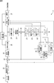
- the image encoding device 11 includes an A / D (Analog / Digital) converter 21, a screen rearrangement buffer 22, an arithmetic unit 23, an orthogonal transformer 24, a quantizer 25, and a lossless encoder 26. , And a storage buffer 27.
- the image coding apparatus 11 further includes an inverse quantization unit 28, an inverse orthogonal transformation unit 29, an operation unit 30, a deblocking filter 31, a frame memory 32, a selection unit 33, an intra prediction unit 34, a motion prediction / compensation unit 35, The prediction image selection unit 36 and the rate control unit 37 are provided.
- the image coding device 11 includes an adaptive offset filter 41 and an adaptive loop filter 42 between the deblocking filter 31 and the frame memory 32.
- the A / D converter 21 A / D converts the input image data, and outputs the image data to the screen rearrangement buffer 22 for storage.
- the screen rearrangement buffer 22 rearranges the images of frames in the stored display order into the order of frames for encoding in accordance with the GOP (Group of Picture) structure.
- the screen rearrangement buffer 22 supplies the image in which the order of the frames is rearranged to the calculation unit 23.
- the screen rearrangement buffer 22 also supplies the image in which the order of the frames is rearranged to the intra prediction unit 34 and the motion prediction / compensation unit 35.
- the arithmetic unit 23 subtracts the predicted image supplied from the intra prediction unit 34 or the motion prediction / compensation unit 35 from the image read from the screen rearrangement buffer 22 via the predicted image selection unit 36, and the difference information thereof Are output to the orthogonal transformation unit 24.
- the operation unit 23 subtracts the predicted image supplied from the intra prediction unit 34 from the image read from the screen rearrangement buffer 22. Also, for example, in the case of an image on which inter coding is performed, the operation unit 23 subtracts the predicted image supplied from the motion prediction / compensation unit 35 from the image read from the screen rearrangement buffer 22.
- the orthogonal transformation unit 24 performs orthogonal transformation such as discrete cosine transformation and Karhunen-Loeve transformation on the difference information supplied from the calculation unit 23, and supplies the transformation coefficient to the quantization unit 25.
- the quantization unit 25 quantizes the transform coefficient output from the orthogonal transform unit 24.
- the quantization unit 25 supplies the quantized transform coefficient to the lossless encoding unit 26.
- the lossless encoding unit 26 performs lossless encoding such as variable-length encoding and arithmetic encoding on the quantized transform coefficient.
- the lossless encoding unit 26 acquires parameters such as information indicating an intra prediction mode from the intra prediction unit 34, and acquires parameters such as information indicating an inter prediction mode or motion vector information from the motion prediction / compensation unit 35.
- the lossless encoding unit 26 encodes the quantized transform coefficients, and encodes each acquired parameter (syntax element) to be part of header information of encoded data (multiplexing).
- the lossless encoding unit 26 supplies the encoded data obtained by the encoding to the accumulation buffer 27 for accumulation.
- variable-length coding examples include CAVLC (Context-Adaptive Variable Length Coding).
- arithmetic coding include CABAC (Context-Adaptive Binary Arithmetic Coding).
- the accumulation buffer 27 temporarily holds the encoded stream (data) supplied from the lossless encoding unit 26, and at a predetermined timing, for example, a not-shown recording at a later stage as an encoded image encoded. Output to a device or transmission line. That is, the accumulation buffer 27 is also a transmission unit that transmits the encoded stream.
- the transform coefficient quantized in the quantization unit 25 is also supplied to the inverse quantization unit 28.
- the inverse quantization unit 28 inversely quantizes the quantized transform coefficient by a method corresponding to the quantization by the quantization unit 25.
- the inverse quantization unit 28 supplies the obtained transform coefficient to the inverse orthogonal transform unit 29.
- the inverse orthogonal transform unit 29 performs inverse orthogonal transform on the supplied transform coefficient by a method corresponding to orthogonal transform processing by the orthogonal transform unit 24.
- the inverse orthogonal transform output (restored difference information) is supplied to the calculation unit 30.
- Arithmetic unit 30 is supplied from intra prediction unit 34 or motion prediction / compensation unit 35 via predicted image selection unit 36 to the inverse orthogonal transformation result supplied from inverse orthogonal transformation unit 29, that is, the restored difference information. Prediction images are added to obtain a locally decoded image (decoded image).
- the calculation unit 30 adds the predicted image supplied from the intra prediction unit 34 to the difference information. Also, for example, when the difference information corresponds to an image on which inter coding is performed, the calculation unit 30 adds the predicted image supplied from the motion prediction / compensation unit 35 to the difference information.
- the decoded image that is the addition result is supplied to the deblocking filter 31 and the frame memory 32.
- the deblocking filter 31 removes block distortion of the decoded image by appropriately performing deblocking filter processing.
- the deblocking filter 31 supplies the filter processing result to the adaptive offset filter 41.
- the adaptive offset filter 41 performs an offset filter (SAO: Sample adaptive offset) process that mainly removes ringing on the image filtered by the deblocking filter 31.
- the adaptive offset filter 41 supplies the filtered image to the adaptive loop filter 42.
- the adaptive offset filter 41 sets information indicating ON / OFF of each component for each slice, and sets an offset filter type (type) and an offset (value) for each LCU which is the maximum coding unit.
- the filter type is commonly set among the components (components) of Y, Cb, and Cr.
- the adaptive offset filter 41 applies a filtering process to the image filtered by the deblocking filter 31 using the set type and the offset.
- Y, Cb, and Cr are simply described, but Y represents a luminance component, Cb represents a Cb color difference component, and Cr represents a Cr color difference component.
- the adaptive offset filter 41 supplies information indicating the set type to the lossless encoding unit 26, and causes the information to be encoded.
- the above-mentioned offset is a coefficient of the filter.
- the offset is also referred to as a coefficient as appropriate. The details of the adaptive offset filter 41 will be described later with reference to FIG.
- the adaptive loop filter 42 performs adaptive loop filter (ALF: Adaptive Loop Filter) processing, for example, for each LCU which is the largest coding unit.
- ALF Adaptive Loop Filter
- a two-dimensional Wiener filter is used as a filter.
- filters other than the winner filter may be used.
- the adaptive loop filter 42 performs filter processing for each LCU on the image filtered by the adaptive offset filter 41 using filter coefficients, and supplies the filter processing result to the frame memory 32.
- the filter coefficients are adaptive loop filters so as to minimize the residual with the original image from the screen rearrangement buffer 12 for each LCU. Calculated by 42 and used.
- the calculated filter coefficients are encoded by the lossless encoding unit 26 and transmitted to the image decoding apparatus 51 of FIG. 3 described later.
- the processing unit of the adaptive loop filter 42 is not limited to this.
- the frame memory 32 outputs the stored reference image to the intra prediction unit 34 or the motion prediction / compensation unit 35 via the selection unit 33 at a predetermined timing.
- the frame memory 32 supplies the reference image to the intra prediction unit 34 via the selection unit 33. Also, for example, when inter coding is performed, the frame memory 32 supplies the reference image to the motion prediction / compensation unit 35 via the selection unit 33.
- the selection unit 33 supplies the reference image to the intra prediction unit 34.
- the selection unit 33 supplies the reference image to the motion prediction / compensation unit 35.
- the intra prediction unit 34 performs intra prediction (in-screen prediction) that generates a predicted image using pixel values in the screen.
- the intra prediction unit 34 performs intra prediction in a plurality of modes (intra prediction modes).
- the intra prediction unit 34 generates predicted images in all intra prediction modes, evaluates each predicted image, and selects an optimal mode. When the optimal intra prediction mode is selected, the intra prediction unit 34 supplies the predicted image generated in the optimal mode to the calculation unit 23 and the calculation unit 30 via the predicted image selection unit 36.
- the intra prediction unit 34 appropriately supplies the lossless encoding unit 26 with parameters such as intra prediction mode information indicating the adopted intra prediction mode.
- the motion prediction / compensation unit 35 uses the input image supplied from the screen rearrangement buffer 22 and the reference image supplied from the frame memory 32 via the selection unit 33 for the image to be inter coded. Make motion predictions. Further, the motion prediction / compensation unit 35 performs motion compensation processing according to the motion vector detected by the motion prediction, and generates a predicted image (inter predicted image information).
- the motion prediction / compensation unit 35 performs inter prediction processing of all the candidate inter prediction modes to generate a prediction image.
- the motion prediction / compensation unit 35 supplies the generated predicted image to the calculation unit 23 and the calculation unit 30 via the predicted image selection unit 36.
- the motion prediction / compensation unit 35 supplies the lossless encoding unit 26 with parameters such as inter prediction mode information indicating the adopted inter prediction mode, and motion vector information indicating the calculated motion vector.
- the predicted image selection unit 36 supplies the output of the intra prediction unit 34 to the calculation unit 23 and the calculation unit 30 in the case of an image to be subjected to intra coding, and the image of the motion prediction / compensation unit 35 in the case of an image to be subjected to inter coding.
- the output is supplied to the arithmetic unit 23 and the arithmetic unit 30.
- the rate control unit 37 controls the rate of the quantization operation of the quantization unit 25 based on the compressed image stored in the storage buffer 27 so that an overflow or an underflow does not occur.
- step S11 the A / D converter 21 A / D converts the input image.
- step S12 the screen rearrangement buffer 22 stores the A / D converted image, and performs rearrangement from the display order of each picture to the coding order.
- the decoded image to be referred to is read from the frame memory 32 and the intra prediction unit via the selection unit 33 It is supplied to 34.
- the intra prediction unit 34 performs intra prediction on the pixels of the block to be processed in all candidate intra prediction modes. Note that as the decoded pixels to be referenced, pixels not filtered by the deblocking filter 31 are used.
- intra prediction is performed in all candidate intra prediction modes, and cost function values are calculated for all candidate intra prediction modes. Then, based on the calculated cost function value, the optimal intra prediction mode is selected, and the predicted image generated by intra prediction in the optimal intra prediction mode and its cost function value are supplied to the predicted image selection unit 36.
- the image to be processed supplied from the screen rearrangement buffer 22 is an image to be inter processed
- the image to be referred to is read from the frame memory 32 and supplied to the motion prediction / compensation unit 35 through the selection unit 33. Be done.
- the motion prediction / compensation unit 35 performs motion prediction / compensation processing based on these images.
- motion prediction processing is performed in all the candidate inter prediction modes, cost function values are calculated for all candidate inter prediction modes, and optimal inter prediction is performed based on the calculated cost function values.
- the mode is determined. Then, the predicted image generated in the optimal inter prediction mode and the cost function value thereof are supplied to the predicted image selection unit 36.
- step S15 the predicted image selection unit 36 optimizes one of the optimal intra prediction mode and the optimal inter prediction mode based on the cost function values output from the intra prediction unit 34 and the motion prediction / compensation unit 35. Decide on prediction mode. Then, the prediction image selection unit 36 selects the prediction image of the determined optimal prediction mode, and supplies it to the calculation units 23 and 30. This predicted image is used for the calculation of steps S16 and S21 described later.
- the selection information of the predicted image is supplied to the intra prediction unit 34 or the motion prediction / compensation unit 35.
- the intra prediction unit 34 supplies the information indicating the optimal intra prediction mode (that is, the parameter related to the intra prediction) to the lossless encoding unit 26.
- the motion prediction / compensation unit 35 losslessly encodes information indicating the optimal inter prediction mode and information according to the optimal inter prediction mode (that is, parameters related to motion prediction) Output to section 26.
- information according to the optimal inter prediction mode include motion vector information and reference frame information.
- step S16 the computing unit 23 computes the difference between the image rearranged in step S12 and the predicted image selected in step S15.
- the predicted image is supplied from the motion prediction / compensation unit 35 in the case of inter prediction, and from the intra prediction unit 34 in the case of intra prediction, to the calculation unit 23 via the predicted image selection unit 36.
- the difference data has a smaller amount of data than the original image data. Therefore, the amount of data can be compressed as compared to the case of encoding the image as it is.
- step S17 the orthogonal transformation unit 24 orthogonally transforms the difference information supplied from the calculation unit 23. Specifically, orthogonal transformation such as discrete cosine transformation and Karhunen-Loeve transformation is performed, and transformation coefficients are output.
- orthogonal transformation such as discrete cosine transformation and Karhunen-Loeve transformation is performed, and transformation coefficients are output.
- step S18 the quantization unit 25 quantizes the transform coefficient.
- the rate is controlled as described in the process of step S28 described later.
- step S19 the inverse quantization unit 28 inversely quantizes the transform coefficient quantized by the quantization unit 25 with a characteristic corresponding to the characteristic of the quantization unit 25.
- step S ⁇ b> 20 the inverse orthogonal transformation unit 29 inversely orthogonally transforms the transform coefficient inversely quantized by the inverse quantization unit 28 with the characteristic corresponding to the characteristic of the orthogonal transformation unit 24.
- step S21 the operation unit 30 adds the predicted image input via the predicted image selection unit 36 to the locally decoded difference information, and the locally decoded (that is, locally decoded) image (The image corresponding to the input to the operation unit 23) is generated.
- step S22 the deblocking filter 31 performs deblocking filter processing on the image output from the computing unit 30. This removes blockiness.
- the filtered image from the deblocking filter 31 is output to the adaptive offset filter 41.
- step S23 the adaptive offset filter 41 performs adaptive offset filter processing.
- the type of offset filter common to the Y, Cb, and Cr components is set for each LCU which is the largest coding unit, and the offset is set for each component.
- the filtering process is performed on the image filtered by the deblocking filter 31 using them. The details of the adaptive offset filter process will be described later with reference to FIG.
- Each type of information common to the components and the offset for each component (hereinafter collectively referred to as an adaptive offset parameter) supplied to the lossless encoding unit 26 is encoded in step S26 described later.
- step S24 the adaptive loop filter 42 performs adaptive loop filter processing on the image filtered by the adaptive offset filter 41. For example, filter processing is performed on the image after filtering by the adaptive offset filter 41 for each LCU using filter coefficients, and the filter processing result is supplied to the frame memory 32.
- step S25 the frame memory 32 stores the filtered image.
- the image not filtered by the deblocking filter 31, the adaptive offset filter 41, and the adaptive loop filter 42 is also supplied from the arithmetic unit 30 and stored.
- the transform coefficient quantized in step S18 described above is also supplied to the lossless encoding unit 26.
- the lossless encoding unit 26 encodes the quantized transform coefficient output from the quantization unit 25 and each supplied parameter. That is, the difference image is losslessly encoded such as variable length coding, arithmetic coding or the like and compressed.
- the parameters of the adaptive offset filter are also encoded.
- step S27 the accumulation buffer 27 accumulates the encoded difference image (that is, the encoded stream) as a compressed image.
- the compressed image stored in the storage buffer 27 is appropriately read and transmitted to the decoding side via the transmission path.
- step S28 the rate control unit 37 controls the rate of the quantization operation of the quantization unit 25 based on the compressed image stored in the storage buffer 27 so that overflow or underflow does not occur.
- step S28 ends, the encoding process ends.
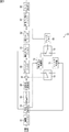
- FIG. 3 shows a configuration of an embodiment of an image decoding apparatus as an image processing apparatus to which the present disclosure is applied.
- the image decoding device 51 shown in FIG. 3 is a decoding device corresponding to the image coding device 11 of FIG.
- the encoded stream (data) encoded by the image encoding device 11 is transmitted to the image decoding device 51 corresponding to the image encoding device 11 via a predetermined transmission path, and is decoded.
- the image decoding device 51 includes an accumulation buffer 61, a lossless decoding unit 62, an inverse quantization unit 63, an inverse orthogonal transformation unit 64, an operation unit 65, a deblocking filter 66, a screen rearrangement buffer 67, And a D / A converter 68.
- the image decoding apparatus 51 further includes a frame memory 69, a selection unit 70, an intra prediction unit 71, a motion prediction / compensation unit 72, and a selection unit 73.
- the image decoding device 51 includes an adaptive offset filter 81 and an adaptive loop filter 82 between the deblocking filter 66 and the screen rearrangement buffer 67 and the frame memory 69.
- the accumulation buffer 61 is also a receiving unit that receives the transmitted encoded data.
- the accumulation buffer 61 receives and accumulates the transmitted encoded data.
- the encoded data is encoded by the image encoding device 11.
- the lossless decoding unit 62 decodes the encoded data read from the accumulation buffer 61 at a predetermined timing in a method corresponding to the encoding method of the lossless encoding unit 26 in FIG. 1.
- the lossless decoding unit 62 supplies parameters such as information indicating the decoded intra prediction mode to the intra prediction unit 71, and supplies parameters such as information indicating the inter prediction mode and motion vector information to the motion prediction / compensation unit 72. .
- the lossless decoding unit 62 uses the adaptive offset filter 81 to decode the decoded adaptive offset parameters (information indicating ON / OFF of each component, information indicating a type common to components for each LCU, offset of each component, etc.). Supply to
- the inverse quantization unit 63 inversely quantizes the coefficient data (quantization coefficient) obtained by being decoded by the lossless decoding unit 62 by a method corresponding to the quantization method of the quantization unit 25 in FIG. 1. That is, the inverse quantization unit 63 performs inverse quantization of the quantization coefficient by the same method as the inverse quantization unit 28 in FIG. 1 using the quantization parameter supplied from the image coding device 11.
- the inverse quantization unit 63 supplies the inversely quantized coefficient data, that is, the orthogonal transformation coefficient to the inverse orthogonal transformation unit 64.
- the inverse orthogonal transformation unit 64 performs inverse orthogonal transformation on the orthogonal transformation coefficient by a method corresponding to the orthogonal transformation method of the orthogonal transformation unit 24 in FIG. 1, and generates residual data before orthogonal transformation in the image encoding device 11. Obtain the corresponding decoded residual data.
- the decoded residual data obtained by the inverse orthogonal transform is supplied to the arithmetic unit 65. Further, the prediction image is supplied to the calculation unit 65 from the intra prediction unit 71 or the motion prediction / compensation unit 72 via the selection unit 73.
- the operation unit 65 adds the decoded residual data and the predicted image to obtain decoded image data corresponding to image data before the predicted image is subtracted by the operation unit 23 of the image coding device 11.
- the operation unit 65 supplies the decoded image data to the deblocking filter 66.
- the deblocking filter 66 removes block distortion of the decoded image by appropriately performing deblocking filter processing.
- the deblocking filter 66 supplies the filtering result to the adaptive offset filter 81.
- the adaptive offset filter 81 performs offset filter (SAO) processing that mainly removes ringing on the image filtered by the deblocking filter 66.
- SAO offset filter
- the adaptive offset filter 81 uses the adaptive offset parameter supplied from the lossless decoding unit 62 to filter the image filtered by the deblocking filter 66 for each LCU, which is the largest coding unit.
- the adaptive offset filter 81 supplies the filtered image to the adaptive loop filter 82.
- the adaptive offset filter 81 is information indicating ON / OFF of each component for each slice, and a type of offset filter for each LCU which is the largest coding unit. Receive (type) and offset (value). Among them, the filter type is commonly set among the Y, Cb, and Cr components.
- the adaptive offset filter 81 filters the image filtered by the deblocking filter 66 using the received type and offset.
- the adaptive loop filter 82 is configured basically in the same manner as the adaptive loop filter 42 of the image coding device 11 of FIG. 1 and performs adaptive loop filter processing for each LCU which is the largest coding unit.
- the adaptive loop filter 82 performs filter processing for each LCU on the image filtered by the adaptive offset filter 81 using filter coefficients, and supplies the filter processing result to the frame memory 69 and the screen rearrangement buffer 67. .
- filter coefficients are calculated for each LUC by the adaptive loop filter 42 of the image coding device 11, encoded and sent. Are decoded by the lossless decoding unit 62 and used.
- the screen rearrangement buffer 67 rearranges the images. That is, the order of the frames rearranged for the order of encoding by the screen rearrangement buffer 22 in FIG. 1 is rearranged in the order of the original display.
- the D / A conversion unit 68 D / A converts the image supplied from the screen rearrangement buffer 67, and outputs the image to a display (not shown) for display.
- the output of the adaptive loop filter 82 is further supplied to a frame memory 69.
- the frame memory 69, the selection unit 70, the intra prediction unit 71, the motion prediction / compensation unit 72, and the selection unit 73 are the frame memory 32, the selection unit 33, the intra prediction unit 34, the motion prediction / compensation unit of the image coding device 11. 35 and the predicted image selection unit 36 respectively.
- the selection unit 70 reads out the image to be inter-processed and the image to be referred to from the frame memory 69 and supplies the same to the motion prediction / compensation unit 72. Further, the selection unit 70 reads an image used for intra prediction from the frame memory 69 and supplies the image to the intra prediction unit 71.
- the intra prediction unit 71 generates a prediction image from the reference image acquired from the frame memory 69 based on this information, and supplies the generated prediction image to the selection unit 73.
- the motion prediction / compensation unit 72 is supplied from the lossless decoding unit 62 with information (prediction mode information, motion vector information, reference frame information, flags, various parameters, and the like) obtained by decoding header information.
- the motion prediction / compensation unit 72 generates a prediction image from the reference image acquired from the frame memory 69 based on the information supplied from the lossless decoding unit 62, and supplies the generated prediction image to the selection unit 73.
- the selection unit 73 selects the prediction image generated by the motion prediction / compensation unit 72 or the intra prediction unit 71, and supplies the prediction image to the calculation unit 65.
- step S51 the accumulation buffer 61 receives and accumulates the transmitted encoded stream (data).
- step S ⁇ b> 52 the lossless decoding unit 62 decodes the encoded data supplied from the accumulation buffer 61.
- the I picture, P picture, and B picture encoded by the lossless encoding unit 26 of FIG. 1 are decoded.
- parameter information such as motion vector information, reference frame information, prediction mode information (intra prediction mode or inter prediction mode) is also decoded.
- the prediction mode information is intra prediction mode information
- the prediction mode information is supplied to the intra prediction unit 71.
- the prediction mode information is inter prediction mode information
- motion vector information and the like corresponding to the prediction mode information are supplied to the motion prediction / compensation unit 72.
- the adaptive offset parameter is also decoded and supplied to the adaptive offset filter 81.
- step S53 the intra prediction unit 71 or the motion prediction / compensation unit 72 performs predicted image generation processing corresponding to the prediction mode information supplied from the lossless decoding unit 62.
- the intra prediction unit 71 when the intra prediction mode information is supplied from the lossless decoding unit 62, the intra prediction unit 71 generates an intra prediction image in the intra prediction mode.
- the motion prediction / compensation unit 72 performs motion prediction / compensation processing in the inter prediction mode to generate an inter prediction image.
- the prediction image (intra prediction image) generated by the intra prediction unit 71 or the prediction image (inter prediction image) generated by the motion prediction / compensation unit 72 is supplied to the selection unit 73.
- step S54 the selection unit 73 selects a predicted image. That is, the predicted image generated by the intra prediction unit 71 or the predicted image generated by the motion prediction / compensation unit 72 is supplied. Therefore, the supplied prediction image is selected and supplied to the calculation unit 65, and is added to the output of the inverse orthogonal transformation unit 64 in step S57 described later.
- the transform coefficient decoded by the lossless decoding unit 62 in step S52 described above is also supplied to the inverse quantization unit 63.
- the inverse quantization unit 63 inversely quantizes the transform coefficient decoded by the lossless decoding unit 62 with a characteristic corresponding to the characteristic of the quantization unit 25 in FIG.
- step S56 the inverse orthogonal transformation unit 29 inversely orthogonally transforms the transform coefficient inversely quantized by the inverse quantization unit 28 with the characteristic corresponding to the characteristic of the orthogonal transformation unit 24 in FIG.
- the difference information corresponding to the input (the output of the arithmetic unit 23) of the orthogonal transform unit 24 in FIG. 1 is decoded.
- step S57 the calculation unit 65 adds the prediction image selected in the process of step S54 described above and input through the selection unit 73 to the difference information. The original image is thus decoded.
- step S58 the deblocking filter 66 performs deblocking filter processing on the image output from the computing unit 65. This removes blockiness.
- the decoded image from the deblocking filter 66 is output to the adaptive offset filter 81.
- step S59 the adaptive offset filter 81 performs adaptive offset filter processing.
- the adaptive offset filter 81 uses the adaptive offset parameter from the lossless decoding unit 62 to filter the image filtered by the deblocking filter 66.
- the adaptive offset filter 81 supplies the filtered image to the adaptive loop filter 82.
- the adaptive offset filter 81 performs adaptive offset filter processing.
- the type of offset filter common to the Y, Cb, and Cr components is set for each LCU which is the largest coding unit, and the offset is set for each component. Further, the image is filtered by the deblocking filter 66 using them.
- step S60 the adaptive loop filter 82 performs adaptive loop filter processing on the image filtered by the adaptive offset filter 81.
- the adaptive loop filter 82 performs filter processing for each LCU on the input image using the filter coefficient calculated for each LCU, which is the largest coding unit, and the filter processing result is displayed on the screen sorting buffer 67 and The frame memory 69 is supplied.
- step S61 the frame memory 69 stores the filtered image.
- step S62 the screen rearrangement buffer 67 rearranges the image after the adaptive loop filter 82. That is, the order of the frames rearranged for encoding by the screen rearrangement buffer 22 of the image encoding device 11 is rearranged in the original display order.
- step S63 the D / A conversion unit 68 D / A converts the image from the screen rearrangement buffer 67. This image is output to a display not shown, and the image is displayed.
- step S63 ends, the decoding process ends.
- the adaptive offset filter 41 is provided between the deblocking filter (DB) 31 and the adaptive loop filter (ALF) 42.
- the adaptive offset filter 81 is provided between the deblocking filter (DB) 66 and the adaptive loop filter (ALF) 82.
- types (types) of adaptive offsets there are two types called band offsets and six types called edge offsets. Furthermore, it is possible to not apply the offsets. Then, for each LCU, it is possible to select which type of adaptive offset described above to encode.
- This selection information is encoded as PQAO Info.
- the encoding unit Entropy Coding
- a bitstream is generated, and the generated bitstream is transmitted to the decoding side.
- 16 bands at the center of 0 to 255 pixels are divided into the first group, and 8 bands on both sides are divided into the second group.
- the offset of only one of the first group and the second group is encoded and sent to the decoding side.
- it is often either black-and-white or have a subtle tint, and it is rare that all of the first group and the second group have pixels. For this reason, by transmitting only one offset, it is possible to suppress an increase in the encoding amount due to transmission of pixel values of values not included in each LCU.
- the luminance signal is limited to 16,235 and the color difference signal is limited to 16,240.
- the broadcast legal shown in the lower part of FIG. 5 is applied, and the offset value for each of the two bands on both sides where the crosses are shown is not transmitted.
- the pixel value is compared with the adjacent pixel value adjacent to the pixel value, and the offset value is transmitted to the category corresponding to this.
- edge offset there are four one-dimensional patterns shown in A to D of FIG. 6 and two two-dimensional patterns shown in E of FIG. 6 and F of FIG.
- the offset is transmitted in the indicated category.
- adjacent pixels are arranged in one dimension on the left and right with respect to the pixel C, that is, 1-D, 0-degree, which makes 0 degrees with respect to the pattern of A in FIG. Represents a pattern.
- adjacent pixels are arranged in the upper and lower one-dimensional with respect to the pixel C, that is, 1-D, 90-degree making 90 degrees with respect to the pattern of A in FIG. Represents a pattern.
- FIG. 6 is such that adjacent pixels are arranged in one dimension in the upper left and lower right with respect to the pixel C, that is, 1-D, which makes 135 degrees with respect to the pattern of A in FIG. It represents the 135-degree pattern.
- adjacent pixels are arranged in the upper right and lower left one-dimensional with respect to the pixel C, that is, 45 degrees with respect to the pattern of A in FIG. -Represents the degree pattern.
- E in FIG. 6 represents a 2-D, cross pattern in which adjacent pixels are arranged in the upper, lower, left, and right directions with respect to the pixel C, that is, intersecting with the pixel C.
- adjacent pixels are two-dimensionally arranged in the upper right lower left and upper left lower right, that is, 2-D diagonally intersecting with the pixel C. Represents a pattern.
- FIG. 7A shows a classification rule for 1-dimensional patterns (Classification rule for 1-D patterns).
- the patterns of A to D in FIG. 6 are classified into five types of categories as shown in A of FIG. 7, and the offset is calculated by the categories and sent to the decoding unit.
- the pixel value of the pixel C is smaller than the pixel values of two adjacent pixels, it is classified into category 1. If the pixel value of the pixel C is smaller than the pixel value of one adjacent pixel and matches the pixel value of the other adjacent pixel, it is classified into category 2. When the pixel value of the pixel C is larger than the pixel value of one adjacent pixel and coincides with the pixel value of the other adjacent pixel, it is classified into category 3. If the pixel value of the pixel C is larger than the pixel values of two adjacent pixels, it is classified into category 4. If none of the above, it is classified into category 0.
- FIG. 7B shows a classification rule for 2-dimensional patterns (Classification rule for 2-D patterns).
- the patterns of E of FIG. 6 and F of FIG. 6 are classified into seven types of categories as shown in B of FIG. 7, and the category sends an offset to the decoding side.
- the pixel value of the pixel C is smaller than the pixel values of four adjacent pixels, it is classified into category 1. If the pixel value of the pixel C is smaller than the pixel values of three adjacent pixels and matches the pixel value of the fourth adjacent pixel, it is classified into category 2. If the pixel value of the pixel C is smaller than the pixel values of three adjacent pixels and is larger than the pixel value of the fourth adjacent pixel, it is classified into category 3.
- the image is classified into category 4. If the pixel value of the pixel C is larger than the pixel values of three adjacent pixels and matches the pixel value of the fourth adjacent pixel, the image is classified into category 5. If the pixel value of the pixel C is larger than the pixel values of four adjacent pixels, it is classified into category 6. If none of the above, it is classified into category 0.
- the edge offset since the one-dimensional pattern only needs to compare two adjacent pixels, the amount of calculation is lower. Note that under the high efficiency coding condition, the value of the 1-bit offset is sent to the decoding side with high accuracy compared to the low delay coding condition.
- the adaptive offset process described above is a process performed for each LCU in the HEVC method (Non-Patent Document 1). Further, in adaptive offset processing in the HEVC scheme, control signals among components of Y, Cb, and Cr are all transmitted independently.
- SAO control information such as ON / OFF information, filter type information, and filter coefficients are all transmitted independently for each LCU and for each component.
- Non-Patent Document 2 a proposal has been made to replace the ON / OFF control signal between components in the above-mentioned SAO control information with one syntax and transmit it.
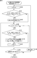
- step S11 component ID (cIdx) is set to 0.
- step S12 it is determined whether cIdx ⁇ 3.
- step S12 it is determined whether cIdx ⁇ 3.
- slice_sample_adaptive_offset_flag [cIdx] is information (flag) indicating ON / OFF of each component for each slice.
- filter type information, a filter coefficient (offset) and the like are sent as SAO control information.
- step S16 it is determined whether the current LCU currently being processed is the last LCU. If it is determined in step S16 that the current LCU currently being processed is not the last LCU, the process proceeds to step S17. In step S17, the next LCU is set as the current LCU, and the process returns to step S11.
- step S16 If it is determined in step S16 that the current LCU currently being processed is the last LCU, the SAO control information transmission process for each LCU is ended.
- SAO control information such as filter type information and filter coefficients are all transmitted independently for each LCU and for each component.
- Non-Patent Documents 1 and 2 described above type information is transmitted independently among the Y, Cb, and Cr components, so the amount of code required for controlling the adaptive offset filter is large.
- the filter type is shared between components (Y, Cb, Cr or Cb, Cr), and only the coefficient is independently transmitted as SAO control information.
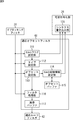
- FIG. 9 is a block diagram showing a configuration example of the adaptive offset filter and the lossless encoding unit in the image encoding device of FIG.
- the adaptive offset filter 41 includes an SAO flag setting unit 111, a type setting unit 112, an offset setting unit 113, an SAO control information setting unit 114, an offset buffer 115, a filter processing unit 116, and an image buffer 117. Configured as.
- the lossless encoding unit 26 is configured to include at least a syntax writing unit 121.
- the deblocked pixel value from the deblocking filter 31 is input to the SAO flag setting unit 111, the type setting unit 112, the offset setting unit 113, and the filter processing unit 116.
- the SAO flag setting unit 111 sets an SAO flag (slice_sample_adaptive_offset_flag) indicating ON / OFF of the adaptive offset filter of each component on a slice basis using the deblocked pixel value.
- the SAO flag setting unit 111 supplies the set SAO flag to the type setting unit 112 and the syntax writing unit 121.
- the type setting unit 112 uses the post-deblock pixel values to set, for each LCU, a filter type common to the Y, Cb, and Cr components. For example, the cost function value is calculated in LCU units, and the optimum type is set for the LCU whose cost function value is the smallest. At that time, signals of all components are used, but the signals used are not limited, and for example, only a luminance signal may be used.
- the type setting unit 112 supplies information indicating the type to the offset setting unit 113 and the syntax writing unit 121.
- the type setting unit 112 also supplies the SAO flag of each component to the offset setting unit 113.
- the offset setting unit 113 sets an offset (coefficient) independent of each component of Y, Cb, and Cr in LCU units using the post-deblock pixel values. At that time, for example, the signal of each component (deblocked pixel value) is used, the cost function value is calculated in LCU units, and the optimal offset is set to the LCU whose cost function value is the smallest. .
- the offset setting unit 113 supplies the filtering unit 116 with the SAO flag and the offset of each component and the type common to the components. Also, the offset setting unit 113 supplies the offset to the SAO control information setting unit 114.
- the SAO control information setting unit 114 writes the offset from the offset setting unit 113 in the offset buffer 115 for each component. Further, the SAO control information setting unit 114 refers to the information written in the offset buffer 115, and whether the offset from the offset setting unit 113 matches the offset of the left LCU adjacent to the left of the current LCU currently being processed It is determined whether or not. If it is determined that they match, the SAO control information setting unit 114 sets sao_merge_left_flag, and supplies the set sao_merge_left_flag to the syntax writing unit 121 as SAO control information.
- SAO control information setting unit 114 determines whether the offset from offset setting unit 113 matches the offset of the upper LCU adjacent above the current LCU. When it is determined that the SAO control information setting unit 114 matches, the SAO control information setting unit 114 sets sao_merge_top_flag, and supplies the set sao_merge_top_flag to the syntax writing unit 121 as SAO control information.
- the SAO control information setting unit 114 supplies only the offset to the syntax writing unit 121 as SAO control information. That is, sao_merge_left_flag is a flag indicating that the offset is the same as the left LCU, sao_merge_top_flag is a flag indicating that the offset is the same as the upper LCU, and when these flags are set, the set flag is , Sent in place of the offset.
- the type and the offset may be supplied from the offset setting unit 113, and the determination may be performed based on the type and the offset.
- the offset buffer 115 holds the offset of the LCU adjacent to the current LCU.
- the offset buffer 115 may hold at least the offsets of the left LCU and the upper LCU of the current LCU.
- the filter processing unit 116 performs adaptive offset filter processing for each LCU on post-deblock pixel values of each component from the deblocking filter 31 based on the SAO flag, type information, and offset information from the offset setting unit 113. Apply.
- the filter processing unit 116 supplies the pixel value after the offset processing to the image buffer 117.
- the image buffer 117 temporarily stores the pixel value after the offset processing by the filter processing unit 116, and supplies the pixel value to the adaptive loop filter 42 at a predetermined timing.
- the syntax writing unit 121 writes the SAO flag from the SAO flag setting unit 111 in the header portion of the encoded stream for each slice.
- the syntax writing unit 121 writes, for each LCU, a type common to components from the type setting unit 112 and an offset or merge flag for each component from the SAO control information setting unit 114 in the header portion of the encoded stream.
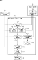
- the deblocked pixel value from the deblocking filter 31 is input to the SAO flag setting unit 111, the type setting unit 112, the offset setting unit 113, and the filter processing unit 116.
- the SAO flag setting unit 111 sets an SAO flag (slice_sample_adaptive_offset_flag) indicating ON / OFF of the adaptive offset filter of each component on a slice basis using the deblocked pixel value.
- the SAO flag setting unit 111 supplies the set SAO flag to the type setting unit 112 and the syntax writing unit 121.
- step S114 the type setting unit 112 sets the filter type (sao_type) common to the Y, Cb, and Cr components on a per LCU basis using the deblocked pixel values.
- the type setting unit 112 supplies information indicating the type to the syntax writing unit 121, and then the process proceeds to step S115.
- the syntax writing unit 121 writes sao_type to the syntax, supplies it to the accumulation buffer 27, and causes it to be transmitted in step S143 of FIG. 12 described later.
- step S115 the type setting unit 112 determines whether cIdx ⁇ 3. If it is determined in step S115 that cIdx ⁇ 3, then the process proceeds to step S116.
- the type setting unit 112 supplies, to the offset setting unit 113, the filter type set in step S114 and the SAO flag (slice_sample_adaptive_offset_flag) of the corresponding cIdx set in step S111.
- SAO control information setting process will be described later with reference to FIG. 11, the offset or merge flag is set as the SAO control information by this process, and the set SAO control information is sent to syntax writing section 121. Supplied. Further, the offset set here is supplied to the filter processing unit 116.
- the syntax writing unit 121 writes SAO control information for cIdx in syntax, supplies it to the accumulation buffer 27, and causes it to be transmitted in step S146 of FIG. 12 described later.
- step S118 the filter processing unit 116 performs adaptive filter processing on the deblocked pixels from the deblocking filter 31. At this time, adaptive filter processing is performed based on the filter type set in step S114, the corresponding cIdx SAO flag set in step S111, and the offset set in step S117.
- the filter processing unit 116 supplies the pixel value after the offset processing to the image buffer 117.
- the image buffer 117 temporarily stores the pixel value after the offset processing by the filter processing unit 116, and supplies the pixel value to the adaptive loop filter 42 at a predetermined timing.
- step S120 the type setting unit 112 determines whether the current LCU currently being processed is the last LCU. If it is determined in step S120 that the current LCU currently being processed is not the last LCU, the process proceeds to step S121. In step S121, the current LCU is moved to the next LCU, and the process returns to step S112.
- step S120 If it is determined in step S120 that the current LCU currently being processed is the last LCU, the adaptive offset filter is ended.
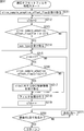
- step S131 the offset setting unit 113 sets an offset (coefficient) independent of each component of cIdx in LCU units using the deblocked pixel value, and the set offset is controlled by the filter processing unit 116 and SAO control.
- the information is supplied to the information setting unit 114.
- step S 132 the SAO control information setting unit 114 writes the offset from the offset setting unit 113 in the offset buffer 115 for each of the Y, Cb, and Cr components.
- step S133 the SAO control information setting unit 114 determines whether the current LCU currently being processed can be merged with the left LCU adjacent to the left of the current LCU. That is, SAO control information setting unit 114 refers to the information written in offset buffer 115, and determines whether the offset of the current LCU from offset setting unit 113 matches the offset of the left LCU.
- step S133 If it is determined in step S133 that the offset of the current LCU from the offset setting unit 113 matches the offset of the left LCU, and it is determined that the current LCU can be merged with the left LCU, the process proceeds to step S134.
- step S134 the SAO control information setting unit 114 sets sao_merge_left_flag, and supplies the set sao_merge_left_flag to the syntax writing unit 121 as SAO control information.
- step S133 when it is determined in step S133 that the current LCU can not be merged with the left LCU, the process proceeds to step S135.
- step S135 the SAO control information setting unit 114 determines whether or not the current LCU currently being processed can be merged with the upper LCU adjacent on the current LCU. That is, SAO control information setting unit 114 refers to the information written in offset buffer 115, and determines whether the offset of the current LCU from offset setting unit 113 matches the offset of the upper LCU.
- step S135 If it is determined in step S135 that the offset of the current LCU from the offset setting unit 113 matches the offset of the upper LCU, and it is determined that the current LCU can be merged with the upper LCU, the process proceeds to step S136.
- step S136 the SAO control information setting unit 114 sets sao_merge_top_flag, and supplies the set sao_merge_top_flag to the syntax writing unit 121 as SAO control information.
- step S135 when it is determined in step S135 that the current LCU can not be merged with the upper LCU, the process proceeds to step S137.
- step S137 the SAO control information setting unit 114 supplies the offset to the syntax writing unit 121 as SAO control information.
- the syntax writing unit 121 writes, in the syntax, information indicating the type (sao_type) of the filter set and supplied in step S114 of FIG. 10, and supplies the information to the accumulation buffer 27 for transmission.
- Information indicating the type is transmitted in PPS (Picture Parameter Set) or slice units.
- step S144 the syntax writing unit 121 determines whether cIdx ⁇ 3. If it is determined that cIdx ⁇ 3 in step S144, the process proceeds to step S145.
- step S148 the syntax writing unit 121 determines whether the current LCU currently being processed is the last LCU. If it is determined in step S148 that the current LCU currently being processed is not the last LCU, the process proceeds to step S149. In step S149, the current LCU is moved to the next LCU, and the process returns to step S141.
- step S148 If it is determined in step S148 that the current LCU currently being processed is the last LCU, the SAO control information transmission process for each LCU is ended.
- FIG. 13 is a block diagram showing another configuration example of the adaptive offset filter and the lossless encoding unit in the image encoding device of FIG.
- the adaptive offset filter 41 includes an SAO flag setting unit 111, an offset setting unit 113, an SAO control information setting unit 114, an offset buffer 115, a filter processing unit 116, and an image buffer 117. Is common to the adaptive offset filter 41 of FIG.
- the adaptive offset filter 41 is different from the adaptive offset filter 41 of FIG. 9 in that the type setting unit 112 is replaced with the type setting unit 141.
- lossless encoding unit 26 in FIG. 13 is different from the lossless encoding unit 26 in FIG. 9 in that the syntax writing unit 121 is replaced with the syntax writing unit 161.
- the type setting unit 141 of FIG. 13 includes a Y type setting unit 151 that sets an independent filter type using luminance signals, and a Cm type setting unit 152 that sets a common filter type between Cb and Cr color difference signals. It is configured to include.
- the Y type setting unit 151 calculates a cost function value, for example, in units of LCU using the luminance signal, and sets an optimal type for the LCU of the luminance signal whose cost function value is minimum.
- the Cm type setting unit 152 calculates a cost function value, for example, in LCU units using at least one of Cb and Cr, and the type that is optimum for the LCU of the color difference signal with the smallest cost function value.
- the syntax writing unit 161 writes the SAO flag from the SAO flag setting unit 111 in the header portion of the encoded stream for each slice. Similar to the syntax writing unit 121, the syntax writing unit 161 writes the offset or merge flag for each component from the SAO control information setting unit 114 in the header portion of the encoded stream.
- the syntax writing unit 161 differs from the syntax writing unit 121 in that for each LCU, the type information indicating the Y type for luminance from the type setting unit 112 and the type information indicating the Cm type common to color difference components are Write to the header part of
- step S161 the SAO flag setting unit 111 sets an SAO flag indicating ON / OFF of the adaptive offset filter of each component in slice units, using the post-deblock pixel values.
- the SAO flag setting unit 111 supplies the set SAO flag (slice_sample_adaptive_offset_flag) to the Y type setting unit 151, the Cm type setting unit 152, and the syntax writing unit 161.
- step S164 the Y type setting unit 151 sets the Y filter type (sao_type_Y) in units of LCU using the deblocked pixel values.
- the Y type setting unit 151 supplies information indicating the type of Y to the syntax writing unit 161, and then the process proceeds to step S165.
- the syntax writing unit 161 writes sao_type_Y to the syntax, supplies it to the accumulation buffer 27, and causes it to be transmitted in step S183 of FIG. 15 described later.
- step S166 the Cm type setting unit 152 sets a filter type (sao_type_Cm) common to Cb and Cr for each LCU using the post-deblocking pixel value.
- the Y type setting unit 151 supplies the information indicating the type of Cm to the syntax writing unit 161, and then the process proceeds to step S167.
- the syntax writing unit 161 writes sao_type_Cm to the syntax, supplies it to the accumulation buffer 27, and causes it to be transmitted in step S185 of FIG. 15 described later.
- the subsequent steps S167 to S173 are basically the same as the steps S115 to S121 of FIG. 10, and thus the description thereof is omitted to avoid repetition.
- the syntax writing unit 161 writes in the syntax the information indicating the type of filter (sao_type_Y) supplied in step S164 of FIG. 14, and supplies the information to the accumulation buffer 27 for transmission.
- step S185 the syntax writing unit 161 writes in the syntax the information indicating the type of filter (sao_type_Cm) supplied in step S166 of FIG. 14, and supplies the information to the accumulation buffer 27 for transmission.
- the subsequent S186 to S191 are basically the same as the steps S144 to S149 of FIG. 14, and thus the description thereof is omitted to avoid repetition.
- FIG. 16 is a block diagram showing a configuration example of the lossless decoding unit and the adaptive offset filter in the image decoding apparatus of FIG.
- the configuration example shown in FIG. 16 corresponds to the adaptive offset filter and the lossless encoding unit in FIG.
- the lossless decoding unit 62 is configured to include at least a syntax acquisition unit 211.
- the adaptive offset filter 81 is configured to include an SAO flag reception unit 221, a type reception unit 222, a merge flag reception unit 223, an offset buffer 224, an offset reception unit 225, a filter processing unit 226, and an image buffer 227.
- the syntax acquisition unit 211 acquires syntax from the header portion of the encoded stream. Then, the syntax acquisition unit 211 supplies the adaptive offset parameter to the SAO flag reception unit 221, the type reception unit 222, the merge flag reception unit 223, and the offset reception unit 225 among the acquired syntax.
- the syntax acquisition unit 211 supplies the SAO flag (slice_sample_adaptive_offset_flag), which is one of the adaptive offset parameters, to the SAO flag reception unit 221.
- the syntax acquisition unit 211 supplies the type information of one of the adaptive offset parameters to the type reception unit 222.
- the syntax acquisition unit 211 supplies the merge flag (sao_merge_left_flag or sao_merge_top_flag), which is one of the adaptive offset parameters, to the merge flag reception unit 223.
- the syntax acquisition unit 211 supplies the offset (coefficient), which is one of the adaptive offset parameters, to the offset reception unit 225.
- the SAO flag is set for each slice and transmitted.
- type information, merge flag, offset and the like are set and transmitted for each LCU.
- the type information is transmitted, for example, in units of PPS (Picture Parameter Set) or slices.
- the SAO flag reception unit 221 supplies, to the filter processing unit 226, an SAO flag indicating ON / OFF of each component supplied from the syntax acquisition unit 211.
- the type reception unit 222 supplies the filter processing unit 226 with filter type information common to the components supplied from the syntax acquisition unit 211.
- the merge flag reception unit 223 supplies the merge flag supplied from the syntax acquisition unit 211 to the offset buffer 224.
- the offset reception unit 225 supplies the offset acquired from the syntax acquisition unit 211 to the offset buffer 224 and the filter processing unit 226.
- the offset buffer 224 holds the offset of the LCU adjacent to the current LCU.
- the offset buffer 224 may hold at least the offsets of the left LCU and the upper LCU of the current LCU.
- the offset buffer 224 reads the offset stored corresponding to the adjacent LCU (left or upper) indicated by the merge flag, and the filtering unit 226 Supply to Then, the offset buffer 224 stores the read offset in association with the current LCU. Also, when receiving the offset for the current LCU from the offset receiving unit 225, the offset buffer 224 stores the received offset in association with the current LCU.
- the filter processing unit 226 filters the deblocking pixel value from the deblocking filter 66 with reference to the information from the SAO flag receiving unit 221, the type receiving unit 222, the offset buffer 224, and the offset receiving unit 225. I do.
- the filter processing unit 226, the SAO flag from the SAO flag receiving unit 221, the filter type shared among the components from the type receiving unit 222, and the offset from the offset buffer 224 or the offset receiving unit 225 are referenced. .
- the filter processing unit 226 supplies the pixel after the offset processing to the image buffer 227.
- the image buffer 227 is basically configured in the same manner as the image buffer 117 of FIG. That is, the image buffer 227 temporarily stores the pixel value after the offset processing by the filter processing unit 226 and supplies the pixel value to the adaptive loop filter 82 at a predetermined timing.
- step S52 in FIG. 4 when the encoded stream is decoded, the syntax acquisition unit 211 reads the syntax from the header portion of the encoded stream, and supplies the adaptive offset parameter to each part of the adaptive offset filter 81 among them. .
- step S211 the SAO flag reception unit 221 receives the SAO flag (slice_sample_adaptive_offset_flag) of the adaptive offset parameter supplied from the syntax acquisition unit 211.
- the SAO flag receiving unit 221 supplies the received SAO flag to the filter processing unit 226.
- slice_sample_adaptive_offset_flag [0 or 1 or 2] 1 in step S213, that is, if it is determined that at least one adaptive offset filter of Y, Cb, and Cr is to be applied, the process proceeds to step S214.
- step S 214 the filter processing unit 226 receives the filter type information (sao_type) shared among the components from the syntax acquisition unit 211 via the type receiving unit 222.
- step S215 the filter processing unit 226 determines whether cIdx ⁇ 3. If it is determined in step S215 that cIdx ⁇ 3 holds, the process proceeds to step S216.
- SAO control information reception process will be described later with reference to FIG. 18, but by this process, a merge flag or offset is received, and the offset read by the received merge flag or the received offset is It is supplied to the filter processing unit 226.
- step S218 the filter processing unit 226 performs adaptive filter processing on the deblocked pixels from the deblocking filter 66. At this time, adaptive filter processing is performed based on the type of filter received in step S214, the corresponding cIdx SAO flag received in step S211, and the offset acquired in step S217.
- the filter processing unit 226 supplies the pixel value after the offset processing to the image buffer 227.
- the image buffer 227 temporarily stores the pixel value after the offset processing by the filter processing unit 226, and supplies the pixel value to the adaptive loop filter 42 at a predetermined timing.
- step S220 the filter processing unit 226 determines whether the current LCU currently being processed is the last LCU. If it is determined in step S220 that the current LCU currently being processed is not the last LCU, the process proceeds to step S221. In step S221, the current LCU is moved to the next LCU, and the process returns to step S212.
- step S220 If it is determined in step S220 that the current LCU currently being processed is the last LCU, the adaptive offset filter processing is terminated.
- step S231 the merge flag receiving unit 223 receives the merge flag.
- step S232 the merge flag receiving unit 223 determines whether sao_merge_left_flag is 1. When it is determined in step S232 that sao_merge_left_flag is 1, the process proceeds to step S233.
- step S233 the merge flag reception unit 223 controls the offset buffer 224 to read the offset of the left LCU, and the offset buffer 224 supplies the read offset of the left LCU to the filter processing unit 226.
- step S232 when it is determined in step S232 that sao_merge_left_flag is 0, the processing proceeds to step S234.
- step S234 the merge flag receiving unit 223 determines whether sao_merge_top_flag is 1. If it is determined in step S234 that sao_merge_top_flag is 1, the processing proceeds to step S235.
- step S235 the merge flag reception unit 223 controls the offset buffer 224 to read the offset of the upper LCU, and the offset buffer 224 supplies the read offset of the upper LCU to the filter processing unit 226.
- step S234 When it is determined in step S234 that sao_merge_top_flag is 0, the process proceeds to step S236.
- step S 236 the offset reception unit 225 receives the offset from the syntax acquisition unit 211 and supplies the offset to the filtering unit 226.
- the offset receiving unit 225 also supplies the received offset to the offset buffer 224.
- step S237 the offset buffer 224 writes the offset read in step S233 or S235 or the offset from the offset receiving unit 225 to the buffer as the offset of the current LCU.
- the information indicating the filter type is sent in common among the Y, Cb, and Cr components, that is, between the luminance and color difference components, only the coefficient (offset) is among the components. It will be transmitted independently, and the amount of coding can be reduced.
- FIG. 19 is a block diagram showing a configuration example of the lossless decoding unit and the adaptive offset filter in the image decoding apparatus of FIG.
- the configuration example shown in FIG. 19 corresponds to the adaptive offset filter and the lossless encoding unit in FIG.
- the lossless decoding unit 62 is different from the lossless decoding unit 62 of FIG. 16 in that the syntax acquisition unit 211 is replaced with the syntax acquisition unit 241.
- the adaptive offset filter 81 is common to the adaptive offset filter 81 of FIG. 16 in that the adaptive offset filter 81 includes an SAO flag receiver 221, a merge flag receiver 223, an offset buffer 224, an offset receiver 225, a filter processor 226, and an image buffer 227. doing.
- the adaptive offset filter 81 differs from the adaptive offset filter 81 of FIG. 16 in that the type receiving unit 222 is replaced by a type receiving unit 251 consisting of a Y type receiving unit 261 and a Cm type receiving unit 262.
- filter type information shared by Y, Cb, and Cr is sent as one of the adaptive offset parameters.
- the filter type information of Y and the filter type information common to Cb and Cr are sent.
- the syntax acquisition unit 241 acquires the SAO flag (slice_sample_adaptive_offset_flag) and supplies the SAO flag (slice_sample_adaptive_offset_flag) to the SAO flag reception unit 221, as in the syntax acquisition unit 211 in FIG.
- the syntax acquisition unit 241 acquires the merge flag (sao_merge_left_flag or sao_merge_top_flag) as in the syntax acquisition unit 211 in FIG. Similar to the syntax acquisition unit 211 of FIG. 16, the syntax acquisition unit 241 acquires an offset and supplies the offset to the offset reception unit 225.
- the syntax acquisition unit 241 acquires Y filter type information and filter type information shared by Cb and Cr, and the Y type reception unit 261 and Cm. The data is supplied to the type receiving unit 262 respectively.
- the Y type receiving unit 261 supplies the filter type information of Y supplied from the syntax acquisition unit 211 to the filtering unit 226.
- the Cm type reception unit 262 supplies the filter type information of Cm, which is shared by Cb and Cr supplied from the syntax acquisition unit 211, to the filter processing unit 226.
- step S261 the SAO flag reception unit 221 receives the SAO flag (slice_sample_adaptive_offset_flag) of the adaptive offset parameter supplied from the syntax acquisition unit 211.
- the SAO flag receiving unit 221 supplies the received SAO flag to the filter processing unit 226.
- step S 264 the filter processing unit 226 receives the Y filter type information (sao_type_Y) from the syntax acquisition unit 241 via the Y type reception unit 261.
- step S266 the filter processing unit 226 receives the filter type information (sao_type_Cm) of Cm from the syntax acquisition unit 241 via the Cm type receiving unit 262.
- steps S267 to S273 are basically the same processes as steps S215 to S221 in FIG. 17, and the description thereof will be omitted as it will be repeated.
- a mode in which types are shared between all luminance and chromaticity components is set as an all common mode
- a mode in which types are shared among color difference components is set as two modes including a color difference common mode. It is also good.
- mode identification information that identifies which mode was used on the encoding side may be sent to the decoding side.
- the transmitted mode identification information is received, the mode is set using the received mode identification information, and the adaptive offset filter is performed.
- filter type information is shared among components of the luminance signal and the color difference signal and transmitted. As a result, the code amount can be reduced, and the coding efficiency can be improved.
- the color format is 4: 2: 0.
- the present technology may be applied to other color formats such as 4: 2: 2 and 4: 4: 4. Can.
- the luminance and the color difference are Y, Cb and Cr has been described, but the luminance and the color difference can be applied to other color spaces such as Y, U and V.
- the HEVC scheme is used as a coding scheme.
- the present disclosure is not limited to this, and another encoding scheme / decoding scheme including at least an adaptive offset filter can be applied as an in-loop filter.
- the present disclosure is, for example, satellite broadcasting, cable television, the Internet, mobile phones, etc. of image information (bit stream) compressed by orthogonal transformation such as discrete cosine transformation and motion compensation as in the HEVC system etc.
- the present invention can be applied to an image encoding device and an image decoding device that are used when receiving via the network media of
- the present disclosure can be applied to an image encoding device and an image decoding device used when processing on storage media such as an optical disk, a magnetic disk, and a flash memory.
- FIG. 21 shows an example of a multi-viewpoint image coding method.
- the multi-viewpoint image includes images of a plurality of viewpoints, and an image of a predetermined one of the plurality of viewpoints is designated as the image of the base view.
- An image of each viewpoint other than the base view image is treated as a non-base view image.
- adaptive offset filter parameters (the above-described SAO flag, filter type information, offset, mode identification information, etc.) may be set in each view (the same view). it can. Also, in each view (different views), adaptive offset filter parameters set in other views can be shared.
- the adaptive offset filter parameters set in the base view are used in at least one non-base view.
- FIG. 22 is a diagram showing a multi-viewpoint image coding apparatus which performs the above-described multi-viewpoint image coding.
- the multi-viewpoint image coding device 600 includes a coding unit 601, a coding unit 602, and a multiplexing unit 603.
- the encoding unit 601 encodes a base view image to generate a base view image coded stream.
- the encoding unit 602 encodes the non-base view image to generate a non-base view image coded stream.
- the multiplexing unit 603 multiplexes the base view image coded stream generated by the coding unit 601 and the non-base view image coded stream generated by the coding unit 602 to generate a multi-view image coded stream. Do.
- the image coding apparatus 11 (FIG. 1) can be applied to the coding unit 601 and the coding unit 602 of the multi-viewpoint image coding apparatus 600.
- the multi-viewpoint image coding apparatus 600 sets and transmits the adaptive offset filter parameter set by the coding unit 601 and the adaptive offset filter parameter set by the coding unit 602.
- the adaptive offset filter parameter set by the encoding unit 601 as described above may be set to be shared and used by the encoding unit 601 and the encoding unit 602 and transmitted.
- the adaptive offset filter parameters collectively set by the coding unit 602 may be set to be shared and used by the coding unit 601 and the coding unit 602 and transmitted.
- FIG. 23 is a diagram illustrating a multi-viewpoint image decoding apparatus that performs the above-described multi-viewpoint image decoding.
- the multi-viewpoint image decoding device 610 includes a demultiplexing unit 611, a decoding unit 612, and a decoding unit 613.
- a demultiplexing unit 611 demultiplexes a multi-view image coded stream in which the base view image coded stream and the non-base view image coded stream are multiplexed, and the base view image coded stream and the non-base view image. Extract the coded stream.
- the decoding unit 612 decodes the base view image coded stream extracted by the demultiplexing unit 611 to obtain a base view image.
- the decoding unit 613 decodes the non-base view image coded stream extracted by the demultiplexing unit 611 to obtain a non-base view image.
- the image decoding device 51 (FIG. 3) can be applied to the decoding unit 612 and the decoding unit 613 of the multi-viewpoint image decoding device 610.
- the multi-viewpoint image decoding apparatus 610 is set by the encoding unit 601 and the adaptive offset filter parameter decoded by the decoding unit 612, and the adaptive offset filter parameter set by the encoding unit 602 and decoded by the decoding unit 613. Use the process.
- the adaptive offset filter parameters set by the encoding unit 601 are set and transmitted so as to be shared and used by the encoding unit 601 and the encoding unit 602.
- the processing is performed using the adaptive offset filter parameter set by the coding unit 601 (or coding unit 602) and decoded by the decoding unit 612 (or decoding unit 613). It will be.
- FIG. 24 shows an example of a multi-viewpoint image coding method.
- the hierarchical image includes images of a plurality of layers (resolutions), and an image of a predetermined layer of the plurality of resolutions is designated as the image of the base layer. Images of each layer other than the image of the base layer are treated as images of the non-base layer.
- adaptive offset filter parameters can be set in each layer (the same layer). Also, in each layer (different layers), adaptive offset filter parameters set in other layers can be shared.
- the adaptive offset filter parameters set in the base layer are used in at least one non-base layer.
- FIG. 25 is a diagram showing a hierarchical image coding apparatus that performs the above-described hierarchical image coding.
- hierarchical image coding apparatus 620 includes coding section 621, coding section 622, and multiplexing section 623.
- the encoding unit 621 encodes a base layer image to generate a base layer image coded stream.
- the encoding unit 622 encodes the non-base layer image to generate a non-base layer image coded stream.
- the multiplexing unit 623 multiplexes the base layer image coded stream generated by the coding unit 621 and the non-base layer image coded stream generated by the coding unit 622 to generate a hierarchical image coded stream. .
- the image coding device 11 (FIG. 1) can be applied to the coding unit 621 and the coding unit 622 of the hierarchical image coding device 620.
- the hierarchical image coding device 620 sets and transmits the adaptive offset filter parameter set by the coding unit 621 and the adaptive offset filter parameter set by the coding unit 602.
- adaptive offset filter parameters set by the encoding unit 621 as described above may be set so as to be shared and used by the encoding unit 621 and the encoding unit 622 and transmitted.
- the adaptive offset filter parameters set by the encoding unit 622 may be set so as to be shared and used by the encoding unit 621 and the encoding unit 622 and transmitted.
- FIG. 26 is a diagram showing a hierarchical image decoding device that performs the hierarchical image decoding described above.
- the hierarchical image decoding device 630 includes a demultiplexer 631, a decoder 632, and a decoder 633.
- a demultiplexing unit 631 demultiplexes the hierarchical image coded stream in which the base layer image coded stream and the non-base layer image coded stream are multiplexed, and the base layer image coded stream and the non-base layer image code Extract the stream of
- the decoding unit 632 decodes the base layer image coded stream extracted by the demultiplexing unit 631 to obtain a base layer image.
- the decoding unit 633 decodes the non-base layer image coded stream extracted by the demultiplexing unit 631 to obtain a non-base layer image.
- the image decoding device 51 (FIG. 3) can be applied to the decoding unit 632 and the decoding unit 633 of the hierarchical image decoding device 630.
- hierarchical image decoding apparatus 630 uses the adaptive offset filter parameters set by encoding unit 621 and decoded by decoding unit 632 and the adaptive offset filter parameters set by encoding unit 622 and decoded by decoding unit 633. Process.
- the adaptive offset filter parameters set by the encoding unit 621 (or the encoding unit 622) as described above are set and transmitted so as to be shared and used by the encoding unit 621 and the encoding unit 622 There is a case.
- the encoding unit 621 (or the encoding unit 622) is set, and the process is performed using the adaptive offset filter parameter decoded by the decoding unit 632 (or the decoding unit 633). It will be.
- the above-described series of processes may be performed by hardware or software.
- a program that configures the software is installed on a computer.
- the computer includes, for example, a general-purpose personal computer that can execute various functions by installing a computer incorporated in dedicated hardware and various programs.
- FIG. 27 is a block diagram showing an example of a hardware configuration of a computer that executes the series of processes described above according to a program.
- a central processing unit (CPU) 801, a read only memory (ROM) 802, and a random access memory (RAM) 803 are mutually connected by a bus 804.
- an input / output interface 805 is connected to the bus 804.
- An input unit 806, an output unit 807, a storage unit 808, a communication unit 809, and a drive 810 are connected to the input / output interface 805.
- the input unit 806 includes a keyboard, a mouse, a microphone, and the like.
- the output unit 807 includes a display, a speaker, and the like.
- the storage unit 808 is formed of a hard disk, a non-volatile memory, or the like.
- the communication unit 809 is formed of a network interface or the like.
- the drive 810 drives removable media 811 such as a magnetic disk, an optical disk, a magneto-optical disk, or a semiconductor memory.
- the CPU 801 loads the program stored in the storage unit 808 into the RAM 803 via the input / output interface 805 and the bus 804, and executes the program. Processing is performed.
- the program executed by the computer 800 can be provided by being recorded on, for example, a removable medium 811 as a package medium or the like. Also, the program can be provided via a wired or wireless transmission medium such as a local area network, the Internet, or digital satellite broadcasting.
- the program can be installed in the storage unit 808 via the input / output interface 805 by attaching the removable media 811 to the drive 810.
- the program can be received by the communication unit 809 via a wired or wireless transmission medium and installed in the storage unit 808.
- the program can be installed in advance in the ROM 802 or the storage unit 808.
- the program executed by the computer may be a program that performs processing in chronological order according to the order described in this specification, in parallel, or when necessary, such as when a call is made. It may be a program to be processed.
- the step of describing the program to be recorded on the recording medium is not limited to processing performed chronologically in the order described, but not necessarily parallel processing It also includes processing to be executed individually.
- system represents the entire apparatus configured by a plurality of devices (apparatus).
- the configuration described above as one device (or processing unit) may be divided and configured as a plurality of devices (or processing units).
- the configuration described as a plurality of devices (or processing units) in the above may be collectively configured as one device (or processing unit).
- configurations other than those described above may be added to the configuration of each device (or each processing unit).
- part of the configuration of one device (or processing unit) may be included in the configuration of another device (or other processing unit) if the configuration or operation of the entire system is substantially the same. . That is, the present technology is not limited to the above-described embodiment, and various modifications can be made without departing from the scope of the present technology.
- the image encoding device and the image decoding device include a transmitter or a receiver in optical satellite, cable broadcasting such as cable TV, distribution on the Internet, and distribution to terminals by cellular communication, etc.
- the present invention can be applied to various electronic devices such as a recording apparatus which records an image on a medium such as a magnetic disk and a flash memory, or a reproduction apparatus which reproduces an image from the storage medium.
- a recording apparatus which records an image on a medium such as a magnetic disk and a flash memory
- a reproduction apparatus which reproduces an image from the storage medium.
- FIG. 28 shows an example of a schematic configuration of a television set to which the embodiment described above is applied.
- the television device 900 includes an antenna 901, a tuner 902, a demultiplexer 903, a decoder 904, a video signal processing unit 905, a display unit 906, an audio signal processing unit 907, a speaker 908, an external interface 909, a control unit 910, a user interface 911, And a bus 912.
- the tuner 902 extracts a signal of a desired channel from a broadcast signal received via the antenna 901, and demodulates the extracted signal. Then, the tuner 902 outputs the coded bit stream obtained by demodulation to the demultiplexer 903. That is, the tuner 902 has a role as a transmission means in the television apparatus 900 for receiving a coded stream in which an image is coded.
- the demultiplexer 903 separates the video stream and audio stream of the program to be viewed from the coded bit stream, and outputs the separated streams to the decoder 904. Also, the demultiplexer 903 extracts auxiliary data such as an EPG (Electronic Program Guide) from the encoded bit stream, and supplies the extracted data to the control unit 910. When the coded bit stream is scrambled, the demultiplexer 903 may perform descrambling.
- EPG Electronic Program Guide
- the decoder 904 decodes the video stream and audio stream input from the demultiplexer 903. Then, the decoder 904 outputs the video data generated by the decoding process to the video signal processing unit 905. Further, the decoder 904 outputs the audio data generated by the decoding process to the audio signal processing unit 907.
- the video signal processing unit 905 reproduces the video data input from the decoder 904 and causes the display unit 906 to display a video. Also, the video signal processing unit 905 may cause the display unit 906 to display an application screen supplied via the network. Further, the video signal processing unit 905 may perform additional processing such as noise removal on the video data according to the setting. Furthermore, the video signal processing unit 905 may generate an image of a graphical user interface (GUI) such as a menu, a button, or a cursor, for example, and may superimpose the generated image on the output image.
- GUI graphical user interface
- the display unit 906 is driven by a drive signal supplied from the video signal processing unit 905, and displays an image on the image surface of a display device (for example, a liquid crystal display, a plasma display, or OELD (Organic ElectroLuminescence Display) (organic EL display)). Or display an image.
- a display device for example, a liquid crystal display, a plasma display, or OELD (Organic ElectroLuminescence Display) (organic EL display)). Or display an image.
- the audio signal processing unit 907 performs reproduction processing such as D / A conversion and amplification on audio data input from the decoder 904, and causes the speaker 908 to output audio. Further, the audio signal processing unit 907 may perform additional processing such as noise removal on the audio data.
- the external interface 909 is an interface for connecting the television device 900 to an external device or a network.
- a video stream or an audio stream received via the external interface 909 may be decoded by the decoder 904. That is, the external interface 909 also serves as a transmission means in the television apparatus 900 for receiving the coded stream in which the image is coded.
- the control unit 910 includes a processor such as a CPU, and memories such as a RAM and a ROM.
- the memory stores a program executed by the CPU, program data, EPG data, data acquired via a network, and the like.
- the program stored by the memory is read and executed by the CPU, for example, when the television device 900 is started.
- the CPU controls the operation of the television apparatus 900 according to an operation signal input from, for example, the user interface 911 by executing a program.
- the user interface 911 is connected to the control unit 910.
- the user interface 911 has, for example, buttons and switches for the user to operate the television device 900, a receiver of remote control signals, and the like.
- the user interface 911 detects an operation by the user via these components, generates an operation signal, and outputs the generated operation signal to the control unit 910.
- the bus 912 mutually connects the tuner 902, the demultiplexer 903, the decoder 904, the video signal processing unit 905, the audio signal processing unit 907, the external interface 909, and the control unit 910.
- the decoder 904 has the function of the image decoding apparatus according to the above-described embodiment. Thus, the code amount can be reduced when decoding an image in the television apparatus 900.
- FIG. 29 shows an example of a schematic configuration of a mobile phone to which the embodiment described above is applied.
- the mobile phone 920 includes an antenna 921, a communication unit 922, an audio codec 923, a speaker 924, a microphone 925, a camera unit 926, an image processing unit 927, a multiplexing and separating unit 928, a recording and reproducing unit 929, a display unit 930, a control unit 931, an operation.
- a unit 932 and a bus 933 are provided.
- the antenna 921 is connected to the communication unit 922.
- the speaker 924 and the microphone 925 are connected to the audio codec 923.
- the operation unit 932 is connected to the control unit 931.
- the bus 933 mutually connects the communication unit 922, the audio codec 923, the camera unit 926, the image processing unit 927, the demultiplexing unit 928, the recording / reproducing unit 929, the display unit 930, and the control unit 931.
- the cellular phone 920 can transmit and receive audio signals, transmit and receive electronic mail or image data, capture an image, and record data in various operation modes including a voice call mode, a data communication mode, a shooting mode, and a videophone mode. Do the action.
- the analog voice signal generated by the microphone 925 is supplied to the voice codec 923.
- the audio codec 923 converts an analog audio signal into audio data, and A / D converts and compresses the converted audio data. Then, the audio codec 923 outputs the compressed audio data to the communication unit 922.
- the communication unit 922 encodes and modulates audio data to generate a transmission signal. Then, the communication unit 922 transmits the generated transmission signal to a base station (not shown) via the antenna 921.
- the communication unit 922 also amplifies and frequency-converts a radio signal received via the antenna 921 to obtain a reception signal.
- the communication unit 922 demodulates and decodes the received signal to generate audio data, and outputs the generated audio data to the audio codec 923.
- the audio codec 923 decompresses and D / A converts audio data to generate an analog audio signal. Then, the audio codec 923 supplies the generated audio signal to the speaker 924 to output audio.
- the control unit 931 generates character data constituting an electronic mail in accordance with an operation by the user via the operation unit 932. Further, the control unit 931 causes the display unit 930 to display characters. Further, the control unit 931 generates electronic mail data in response to a transmission instruction from the user via the operation unit 932, and outputs the generated electronic mail data to the communication unit 922.
- a communication unit 922 encodes and modulates electronic mail data to generate a transmission signal. Then, the communication unit 922 transmits the generated transmission signal to a base station (not shown) via the antenna 921. The communication unit 922 also amplifies and frequency-converts a radio signal received via the antenna 921 to obtain a reception signal.
- the communication unit 922 demodulates and decodes the received signal to restore the e-mail data, and outputs the restored e-mail data to the control unit 931.
- the control unit 931 causes the display unit 930 to display the content of the e-mail, and stores the e-mail data in the storage medium of the recording and reproduction unit 929.
- the recording and reproducing unit 929 includes an arbitrary readable and writable storage medium.
- the storage medium may be a built-in storage medium such as RAM or flash memory, and may be an externally mounted type such as hard disk, magnetic disk, magneto-optical disk, optical disk, USB (Universal Serial Bus) memory, or memory card Storage media.
- the camera unit 926 captures an image of a subject to generate image data, and outputs the generated image data to the image processing unit 927.
- the image processing unit 927 encodes the image data input from the camera unit 926, and stores the encoded stream in the storage medium of the storage and reproduction unit 929.
- the demultiplexing unit 928 multiplexes the video stream encoded by the image processing unit 927 and the audio stream input from the audio codec 923, and the communication unit 922 multiplexes the multiplexed stream.
- Output to The communication unit 922 encodes and modulates the stream to generate a transmission signal.
- the communication unit 922 transmits the generated transmission signal to a base station (not shown) via the antenna 921.
- the communication unit 922 also amplifies and frequency-converts a radio signal received via the antenna 921 to obtain a reception signal.
- the transmission signal and the reception signal may include a coded bit stream.
- the communication unit 922 demodulates and decodes the received signal to restore the stream, and outputs the restored stream to the demultiplexing unit 928.
- the demultiplexing unit 928 separates the video stream and the audio stream from the input stream, and outputs the video stream to the image processing unit 927 and the audio stream to the audio codec 923.
- the image processing unit 927 decodes the video stream to generate video data.
- the video data is supplied to the display unit 930, and the display unit 930 displays a series of images.
- the audio codec 923 decompresses and D / A converts the audio stream to generate an analog audio signal. Then, the audio codec 923 supplies the generated audio signal to the speaker 924 to output audio.
- the image processing unit 927 has functions of the image encoding device and the image decoding device according to the above-described embodiment.
- the coding amount can be reduced when encoding and decoding an image in the mobile phone 920.
- FIG. 30 shows an example of a schematic configuration of a recording and reproducing apparatus to which the embodiment described above is applied.
- the recording / reproducing device 940 encodes, for example, audio data and video data of the received broadcast program, and records the encoded data on a recording medium.
- the recording and reproduction device 940 may encode, for example, audio data and video data acquired from another device and record the encoded data on a recording medium.
- the recording / reproducing device 940 reproduces the data recorded on the recording medium on the monitor and the speaker, for example, in accordance with the user's instruction. At this time, the recording / reproducing device 940 decodes the audio data and the video data.
- the recording / reproducing apparatus 940 includes a tuner 941, an external interface 942, an encoder 943, an HDD (Hard Disk Drive) 944, a disk drive 945, a selector 946, a decoder 947, an OSD (On-Screen Display) 948, a control unit 949, and a user interface. And 950.
- the tuner 941 extracts a signal of a desired channel from a broadcast signal received via an antenna (not shown) and demodulates the extracted signal. Then, the tuner 941 outputs the coded bit stream obtained by demodulation to the selector 946. That is, the tuner 941 has a role as a transmission means in the recording / reproducing device 940.
- the external interface 942 is an interface for connecting the recording and reproducing device 940 to an external device or a network.
- the external interface 942 may be, for example, an IEEE 1394 interface, a network interface, a USB interface, or a flash memory interface.
- video data and audio data received via the external interface 942 are input to the encoder 943. That is, the external interface 942 has a role as a transmission unit in the recording / reproducing device 940.
- the encoder 943 encodes video data and audio data when the video data and audio data input from the external interface 942 are not encoded. Then, the encoder 943 outputs the coded bit stream to the selector 946.
- the HDD 944 records an encoded bit stream obtained by compressing content data such as video and audio, various programs, and other data in an internal hard disk. Also, the HDD 944 reads these data from the hard disk when reproducing video and audio.
- the disk drive 945 records and reads data on the attached recording medium.
- the recording medium mounted on the disk drive 945 is, for example, a DVD disk (DVD-Video, DVD-RAM, DVD-R, DVD-RW, DVD + R, DVD + RW, etc.) or Blu-ray (registered trademark) disk, etc. It may be.
- the selector 946 selects the coded bit stream input from the tuner 941 or the encoder 943 at the time of recording video and audio, and outputs the selected coded bit stream to the HDD 944 or the disk drive 945. Also, the selector 946 outputs the encoded bit stream input from the HDD 944 or the disk drive 945 to the decoder 947 at the time of reproduction of video and audio.
- the decoder 947 decodes the coded bit stream to generate video data and audio data. Then, the decoder 947 outputs the generated video data to the OSD 948. Also, the decoder 904 outputs the generated audio data to an external speaker.
- the OSD 948 reproduces the video data input from the decoder 947 and displays the video.
- the OSD 948 may superimpose an image of a GUI such as a menu, a button, or a cursor on the video to be displayed.
- the control unit 949 includes a processor such as a CPU, and memories such as a RAM and a ROM.
- the memory stores programs executed by the CPU, program data, and the like.
- the program stored by the memory is read and executed by the CPU, for example, when the recording and reproducing device 940 is started.
- the CPU controls the operation of the recording / reproducing apparatus 940 in accordance with an operation signal input from, for example, the user interface 950 by executing a program.
- the user interface 950 is connected to the control unit 949.
- the user interface 950 includes, for example, buttons and switches for the user to operate the recording and reproducing device 940, a receiver of a remote control signal, and the like.
- the user interface 950 detects an operation by the user via these components, generates an operation signal, and outputs the generated operation signal to the control unit 949.
- the encoder 943 has the function of the image coding apparatus according to the embodiment described above.
- the decoder 947 has the function of the image decoding apparatus according to the above-described embodiment. As a result, the code amount can be reduced when encoding and decoding an image in the recording and reproducing device 940.
- FIG. 31 shows an example of a schematic configuration of an imaging device to which the embodiment described above is applied.
- the imaging device 960 captures an object to generate an image, encodes image data, and records the image data in a recording medium.
- the imaging device 960 includes an optical block 961, an imaging unit 962, a signal processing unit 963, an image processing unit 964, a display unit 965, an external interface 966, a memory 967, a media drive 968, an OSD 969, a control unit 970, a user interface 971, and a bus. 972 is provided.
- the optical block 961 is connected to the imaging unit 962.
- the imaging unit 962 is connected to the signal processing unit 963.
- the display unit 965 is connected to the image processing unit 964.
- the user interface 971 is connected to the control unit 970.
- the bus 972 mutually connects the image processing unit 964, the external interface 966, the memory 967, the media drive 968, the OSD 969, and the control unit 970.
- the optical block 961 has a focus lens, an aperture mechanism, and the like.
- the optical block 961 forms an optical image of a subject on the imaging surface of the imaging unit 962.
- the imaging unit 962 includes an image sensor such as a charge coupled device (CCD) or a complementary metal oxide semiconductor (CMOS), and converts an optical image formed on an imaging surface into an image signal as an electrical signal by photoelectric conversion. Then, the imaging unit 962 outputs the image signal to the signal processing unit 963.
- CCD charge coupled device
- CMOS complementary metal oxide semiconductor
- the signal processing unit 963 performs various camera signal processing such as knee correction, gamma correction, and color correction on the image signal input from the imaging unit 962.
- the signal processing unit 963 outputs the image data after camera signal processing to the image processing unit 964.
- the image processing unit 964 encodes the image data input from the signal processing unit 963 to generate encoded data. Then, the image processing unit 964 outputs the generated encoded data to the external interface 966 or the media drive 968. The image processing unit 964 also decodes encoded data input from the external interface 966 or the media drive 968 to generate image data. Then, the image processing unit 964 outputs the generated image data to the display unit 965.
- the image processing unit 964 may output the image data input from the signal processing unit 963 to the display unit 965 to display an image. The image processing unit 964 may superimpose the display data acquired from the OSD 969 on the image to be output to the display unit 965.
- the OSD 969 generates an image of a GUI such as a menu, a button, or a cursor, for example, and outputs the generated image to the image processing unit 964.
- a GUI such as a menu, a button, or a cursor
- the external interface 966 is configured as, for example, a USB input / output terminal.
- the external interface 966 connects the imaging device 960 and the printer, for example, when printing an image.
- a drive is connected to the external interface 966 as necessary.
- removable media such as a magnetic disk or an optical disk may be attached to the drive, and a program read from the removable media may be installed in the imaging device 960.
- the external interface 966 may be configured as a network interface connected to a network such as a LAN or the Internet. That is, the external interface 966 has a role as a transmission unit in the imaging device 960.
- the recording medium mounted in the media drive 968 may be, for example, any readable / writable removable medium such as a magnetic disk, a magneto-optical disk, an optical disk, or a semiconductor memory.
- the recording medium may be fixedly attached to the media drive 968, and a non-portable storage unit such as, for example, a built-in hard disk drive or a solid state drive (SSD) may be configured.
- SSD solid state drive
- the control unit 970 includes a processor such as a CPU, and memories such as a RAM and a ROM.
- the memory stores programs executed by the CPU, program data, and the like.
- the program stored by the memory is read and executed by the CPU, for example, when the imaging device 960 starts up.
- the CPU controls the operation of the imaging device 960 according to an operation signal input from, for example, the user interface 971 by executing a program.
- the user interface 971 is connected to the control unit 970.
- the user interface 971 includes, for example, buttons and switches for the user to operate the imaging device 960.
- the user interface 971 detects an operation by the user via these components, generates an operation signal, and outputs the generated operation signal to the control unit 970.
- the image processing unit 964 has functions of the image coding device and the image decoding device according to the above-described embodiment.
- the coding amount can be reduced when encoding and decoding an image in the imaging device 960.
- the method of transmitting such information is not limited to such an example.
- the information may be transmitted or recorded as separate data associated with the coded bit stream without being multiplexed into the coded bit stream.
- the term “associate” allows an image (a slice or a block, which may be a part of an image) included in a bitstream to be linked at the time of decoding with information corresponding to the image. Means That is, the information may be transmitted on a different transmission path from the image (or bit stream).
- the information may be recorded on a recording medium (or another recording area of the same recording medium) different from the image (or bit stream).
- the information and the image (or bit stream) may be associated with each other in any unit such as, for example, a plurality of frames, one frame, or a part in a frame.
- the present technology can also have the following configurations.
- a decoding unit that decodes an encoded stream to generate an image;
- An image processing apparatus comprising: an adaptive offset filter unit configured to perform an adaptive offset filter on an image generated by the decoding unit according to a type of an applied offset filter common to components of the image.
- an adaptive offset filter unit configured to perform an adaptive offset filter on an image generated by the decoding unit according to a type of an applied offset filter common to components of the image.
- the type of the adaptive offset filter is common to the luminance component and the color difference component of the image.
- a type of the adaptive offset filter is common to color difference components of the image.
- the type of the adaptive offset filter is common to the first color difference component and the second color difference component.
- the type of adaptive offset filter for the first color difference component is a band offset
- the type of adaptive offset filter for the second color difference component is a band offset
- the type of adaptive offset filter for the first color difference component is edge offset
- the type of adaptive offset filter for the second color difference component is edge offset
- the image processing apparatus according to (4) wherein a pattern rule of edge offset is common among color difference components of the image when the type of the adaptive offset filter is edge offset.
- the type of offset filter for the first color difference component is a one-dimensional pattern of edge offset
- the type of offset filter for the second color difference component is a one-dimensional pattern of edge offset (7)
- the type of offset filter for the first color difference component is a two-dimensional pattern of edge offsets
- the type of offset filter for the second color difference components is a two-dimensional pattern of edge offsets (7)
- the image processing apparatus according to claim 1. (10) When the type of offset filter for the first color difference component is a type to which the offset is not applied, the type of offset filter for the second color difference component is a type to which the offset is not applied.
- Image processing device (11) The image processing apparatus according to any one of (1) to (10), wherein a color space of the image is a Y / Cb / Cr format.
- the receiver further includes a receiver configured to receive the encoded stream and type information indicating a type of adaptive offset filter common to components of the image.
- the image processing apparatus according to any one of (1) to (11), wherein the decoding unit decodes the encoded stream received by the receiving unit using the type information received by the receiving unit. (13)
- the image processing apparatus further includes a deblocking filter unit that performs a deblocking filter on the image generated by the decoding unit.
- the image processing apparatus according to any one of (1) to (12), wherein the adaptive offset filter unit performs an adaptive offset filter on the image on which the deblocking filter has been performed by the deblocking filter unit.
- the receiving unit receives a merge flag indicating that the offset is the same as the adjacent coding unit adjacent to the Current coding unit, The image processing according to any one of (1) to (13), wherein the adaptive offset filter unit performs an adaptive offset filter on the image generated by the decoding unit using the merge flag received by the reception unit. apparatus.
- (15) Decode the encoded stream to generate an image, An image processing method for performing adaptive offset filtering on a generated image according to a type of adaptive offset filter common to components of the image.
Abstract
Description
1.装置および動作の概要
2.従来の手法の説明
3.第1の実施の形態(画像処理装置(符号化側))
4.第2の実施の形態(画像処理装置(復号側))
5.第3の実施の形態(多視点画像符号化・多視点画像復号装置)
6.第4の実施の形態(階層画像符号化・階層画像復号装置)
7.第5の実施の形態(コンピュータ)
8.応用例 Hereinafter, modes for carrying out the present disclosure (hereinafter referred to as embodiments) will be described. The description will be made in the following order.
1. Device and Operation Overview Description of conventional method First embodiment (image processing apparatus (coding side))
4. Second embodiment (image processing apparatus (decoding side))
5. Third embodiment (multi-viewpoint image coding / multi-viewpoint image decoding apparatus)
6. Fourth Embodiment (Hierarchical Image Coding / Hierarchical Image Decoding Device)
7. Fifth Embodiment (Computer)
8. Application example
[画像符号化装置の構成例]
図1は、本開示を適用した画像処理装置としての画像符号化装置の一実施の形態の構成を表している。 <1. Device and Operation Overview>
[Configuration Example of Image Encoding Device]
FIG. 1 shows a configuration of an embodiment of an image coding apparatus as an image processing apparatus to which the present disclosure is applied.
図2を参照して、以上のような画像符号化装置11により実行される符号化処理の流れについて説明する。 [Operation of Image Coding Device]
The flow of the encoding process performed by the image encoding apparatus 11 as described above will be described with reference to FIG.
図3は、本開示を適用した画像処理装置としての画像復号装置の一実施の形態の構成を表している。図3に示される画像復号装置51は、図1の画像符号化装置11に対応する復号装置である。 [Configuration Example of Image Decoding Device]
FIG. 3 shows a configuration of an embodiment of an image decoding apparatus as an image processing apparatus to which the present disclosure is applied. The
図4を参照して、以上のような画像復号装置51により実行される復号処理の流れの例を説明する。 [Operation of image decoding apparatus]
An example of the flow of the decoding process performed by the
[HEVC方式における適応オフセット処理]
次に、HEVC方式における適応オフセットフィルタについて説明する。HEVC方式においては、Sample Adaptive Offset方式が採用されている。 <Description of the conventional method>
[Adaptive offset processing in HEVC scheme]
Next, an adaptive offset filter in the HEVC system will be described. The Sample Adaptive Offset method is adopted in the HEVC method.
[適応オフセットフィルタの構成例]
図9は、図1の画像符号化装置における適応オフセットフィルタおよび可逆符号化部の構成例を示すブロック図である。 <3. First embodiment>
[Configuration example of adaptive offset filter]
FIG. 9 is a block diagram showing a configuration example of the adaptive offset filter and the lossless encoding unit in the image encoding device of FIG.
次に、図10のフローチャートを参照して、図9の適応オフセットフィルタ41が行う適応オフセットフィルタ処理について説明する。なお、この適応オフセットフィルタ処理は、図2のステップS23における処理である。 [Adaptive offset filtering on the encoding side]
Next, the adaptive offset filter processing performed by the adaptive offset
次に、図11のフローチャートを参照して、図10のステップS117のSAO制御情報設定処理を説明する。 [SAO control information setting process]
Next, the SAO control information setting process of step S117 of FIG. 10 will be described with reference to the flowchart of FIG.
次に、図12のフローチャートを参照して、図8の従来例に対する、LCU毎のSAO制御情報伝送処理を説明する。なお、この処理は、図10を参照して上述した適応オフセットフィルタ処理に対応して、例えば、図2のステップS26の符号化処理において行われる処理である。 [SAO control information transmission process for each LCU]
Next, SAO control information transmission processing for each LCU with respect to the conventional example of FIG. 8 will be described with reference to the flowchart of FIG. Note that this process is a process performed, for example, in the encoding process of step S26 in FIG. 2 corresponding to the adaptive offset filter process described above with reference to FIG.
図13は、図1の画像符号化装置における適応オフセットフィルタおよび可逆符号化部の他の構成例を示すブロック図である。 [Another Configuration Example of Adaptive Offset Filter]
FIG. 13 is a block diagram showing another configuration example of the adaptive offset filter and the lossless encoding unit in the image encoding device of FIG.
次に、図14のフローチャートを参照して、図13の適応オフセットフィルタ41が行う適応オフセットフィルタ処理について説明する。なお、この適応オフセットフィルタ処理は、図2のステップS23における処理である。 [Adaptive offset filtering on the encoding side]
Next, the adaptive offset filter processing performed by the adaptive offset
次に、図15のフローチャートを参照して、図8の従来例に対する、LCU毎のSAO制御情報伝送処理を説明する。なお、この処理は、図14を参照して上述した適応オフセットフィルタ処理に対応して、例えば、図2のステップS26の符号化処理において行われる処理である。 [SAO control information transmission process for each LCU]
Next, SAO control information transmission processing for each LCU with respect to the conventional example of FIG. 8 will be described with reference to the flowchart of FIG. Note that this process is a process performed, for example, in the encoding process of step S26 in FIG. 2 corresponding to the adaptive offset filter process described above with reference to FIG.
[適応オフセットフィルタの構成例]
図16は、図3の画像復号装置における可逆復号部および適応オフセットフィルタの構成例を示すブロック図である。なお、図16に示す構成例は、図9の適応オフセットフィルタと可逆符号化部に対応している。 <4. Fifth embodiment>
[Configuration example of adaptive offset filter]
FIG. 16 is a block diagram showing a configuration example of the lossless decoding unit and the adaptive offset filter in the image decoding apparatus of FIG. The configuration example shown in FIG. 16 corresponds to the adaptive offset filter and the lossless encoding unit in FIG.
次に、図17のフローチャートを参照して、図16の適応オフセットフィルタ81が行う適応オフセットフィルタ処理について説明する。なお、この適応オフセットフィルタ処理は、図4のステップS59における処理である。 [Adaptive offset filtering on the decoding side]
Next, the adaptive offset filter processing performed by the adaptive offset
次に、図18のフローチャートを参照して、図17のステップS217のSAO制御情報受け取り処理を説明する。 [SAO control information setting process]
Next, the SAO control information reception process of step S217 of FIG. 17 will be described with reference to the flowchart of FIG.
図19は、図3の画像復号装置における可逆復号部および適応オフセットフィルタの構成例を示すブロック図である。なお、図19に示す構成例は、図13の適応オフセットフィルタと可逆符号化部に対応している。 [Another Configuration Example of Adaptive Offset Filter]
FIG. 19 is a block diagram showing a configuration example of the lossless decoding unit and the adaptive offset filter in the image decoding apparatus of FIG. The configuration example shown in FIG. 19 corresponds to the adaptive offset filter and the lossless encoding unit in FIG.
次に、図20のフローチャートを参照して、図19の適応オフセットフィルタ81が行う適応オフセットフィルタ処理について説明する。なお、この適応オフセットフィルタ処理は、図4のステップS59における処理である。 [Adaptive offset filtering on the decoding side]
Next, the adaptive offset filter processing performed by the adaptive offset
[多視画像点符号化・多視点画像復号への適用]
上述した一連の処理は、多視点画像符号化・多視点画像復号に適用することができる。図21は、多視点画像符号化方式の一例を示す。 <5. Third embodiment>
[Application to multi-view image point coding / multi-view image decoding]
The series of processes described above can be applied to multi-view image coding / multi-view image decoding. FIG. 21 shows an example of a multi-viewpoint image coding method.
図22は、上述した多視点画像符号化を行う多視点画像符号化装置を示す図である。図22に示されるように、多視点画像符号化装置600は、符号化部601、符号化部602、および多重化部603を有する。 [Multi-view image coding device]
FIG. 22 is a diagram showing a multi-viewpoint image coding apparatus which performs the above-described multi-viewpoint image coding. As illustrated in FIG. 22, the multi-viewpoint
図23は、上述した多視点画像復号を行う多視点画像復号装置を示す図である。図23に示されるように、多視点画像復号装置610は、逆多重化部611、復号部612、および復号部613を有する。 [Multi-view image decoding device]
FIG. 23 is a diagram illustrating a multi-viewpoint image decoding apparatus that performs the above-described multi-viewpoint image decoding. As illustrated in FIG. 23, the multi-viewpoint
[階層画像点符号化・階層画像復号への適用]
上述した一連の処理は、階層画像符号化・階層画像復号に適用することができる。図24は、多視点画像符号化方式の一例を示す。 <6. Fourth embodiment>
[Application to hierarchical image point coding / hierarchical image decoding]
The series of processes described above can be applied to hierarchical image coding / hierarchical image decoding. FIG. 24 shows an example of a multi-viewpoint image coding method.
図25は、上述した階層画像符号化を行う階層画像符号化装置を示す図である。図25に示されるように、階層画像符号化装置620は、符号化部621、符号化部622、および多重化部623を有する。 [Hierarchical image coding device]
FIG. 25 is a diagram showing a hierarchical image coding apparatus that performs the above-described hierarchical image coding. As shown in FIG. 25, hierarchical
図26は、上述した階層画像復号を行う階層画像復号装置を示す図である。図26に示されるように、階層画像復号装置630は、逆多重化部631、復号部632、および復号部633を有する。 [Layered image decoding apparatus]
FIG. 26 is a diagram showing a hierarchical image decoding device that performs the hierarchical image decoding described above. As shown in FIG. 26, the hierarchical
[コンピュータの構成例]
上述した一連の処理は、ハードウエアにより実行することもできるし、ソフトウエアにより実行することもできる。一連の処理をソフトウエアにより実行する場合には、そのソフトウエアを構成するプログラムが、コンピュータにインストールされる。ここで、コンピュータには、専用のハードウエアに組み込まれているコンピュータや、各種のプログラムをインストールすることで、各種の機能を実行することが可能な、例えば汎用のパーソナルコンピュータなどが含まれる。 <7. Fifth embodiment>
[Computer configuration example]
The above-described series of processes may be performed by hardware or software. When the series of processes are performed by software, a program that configures the software is installed on a computer. Here, the computer includes, for example, a general-purpose personal computer that can execute various functions by installing a computer incorporated in dedicated hardware and various programs.
[第1の応用例:テレビジョン受像機]
図28は、上述した実施形態を適用したテレビジョン装置の概略的な構成の一例を示している。テレビジョン装置900は、アンテナ901、チューナ902、デマルチプレクサ903、デコーダ904、映像信号処理部905、表示部906、音声信号処理部907、スピーカ908、外部インタフェース909、制御部910、ユーザインタフェース911、及びバス912を備える。 <8. Application example>
[First application example: television receiver]
FIG. 28 shows an example of a schematic configuration of a television set to which the embodiment described above is applied. The
図29は、上述した実施形態を適用した携帯電話機の概略的な構成の一例を示している。携帯電話機920は、アンテナ921、通信部922、音声コーデック923、スピーカ924、マイクロホン925、カメラ部926、画像処理部927、多重分離部928、記録再生部929、表示部930、制御部931、操作部932、及びバス933を備える。 [Second application: mobile phone]
FIG. 29 shows an example of a schematic configuration of a mobile phone to which the embodiment described above is applied. The
図30は、上述した実施形態を適用した記録再生装置の概略的な構成の一例を示している。記録再生装置940は、例えば、受信した放送番組の音声データ及び映像データを符号化して記録媒体に記録する。また、記録再生装置940は、例えば、他の装置から取得される音声データ及び映像データを符号化して記録媒体に記録してもよい。また、記録再生装置940は、例えば、ユーザの指示に応じて、記録媒体に記録されているデータをモニタ及びスピーカ上で再生する。このとき、記録再生装置940は、音声データ及び映像データを復号する。 [Third application example: recording / reproducing apparatus]
FIG. 30 shows an example of a schematic configuration of a recording and reproducing apparatus to which the embodiment described above is applied. The recording / reproducing
図31は、上述した実施形態を適用した撮像装置の概略的な構成の一例を示している。撮像装置960は、被写体を撮像して画像を生成し、画像データを符号化して記録媒体に記録する。 [Fourth Application Example: Imaging Device]
FIG. 31 shows an example of a schematic configuration of an imaging device to which the embodiment described above is applied. The
(1) 符号化ストリームを復号処理して、画像を生成する復号部と、
前記画像のコンポーネント間で共通である適用オフセットフィルタのタイプに従って、前記復号部により生成された画像に適応オフセットフィルタを行う適応オフセットフィルタ部
を備える画像処理装置。
(2) 前記適応オフセットフィルタのタイプは、前記画像の輝度成分と色差成分とで共通である
前記(1)に記載の画像処理装置。
(3) 前記適応オフセットフィルタのタイプは、前記画像の色差成分間で共通である
前記(1)に記載の画像処理装置。
(4) 前記適応オフセットフィルタのタイプは、第1の色差成分と第2の色差成分とで共通である
前記(3)に記載の画像処理装置。
(5) 前記第1の色差成分に対する適応オフセットフィルタのタイプがバンドオフセットである場合に、前記第2の色差成分に対する適応オフセットフィルタのタイプはバンドオフセットである
前記(4)に記載の画像処理装置。
(6) 前記第1の色差成分に対する適応オフセットフィルタのタイプがエッジオフセットである場合に、前記第2の色差成分に対する適応オフセットフィルタのタイプはエッジオフセットである
前記(4)に記載の画像処理装置。
(7) 前記適応オフセットフィルタのタイプがエッジオフセットである場合に、エッジオフセットのパターン規則が前記画像の色差成分間で共通である
前記(4)に記載の画像処理装置。
(8) 前記第1の色差成分に対するオフセットフィルタのタイプがエッジオフセットの1次元パターンである場合に、前記第2の色差成分に対するオフセットフィルタのタイプはエッジオフセットの1次元パターンである
前記(7)に記載の画像処理装置。
(9) 前記第1の色差成分に対するオフセットフィルタのタイプがエッジオフセットの2次元パターンである場合に、前記第2の色差成分に対するオフセットフィルタのタイプはエッジオフセットの2次元パターンである
前記(7)に記載の画像処理装置。
(10) 前記第1の色差成分に対するオフセットフィルタのタイプがオフセットを適用しないタイプである場合に、前記第2の色差成分に対するオフセットフィルタのタイプはオフセットを適用しないタイプである
前記(4)に記載の画像処理装置。
(11) 前記画像のカラースペースは、Y/Cb/Crフォーマットである
前記(1)乃至(10)のいずれかに記載の画像処理装置。
(12) 前記符号化ストリームと、前記画像のコンポーネント間で共通である適応オフセットフィルタのタイプを示すタイプ情報とを受け取る受け取り部を
さらに備え、
前記復号部は、前記受け取り部により受け取られたタイプ情報を用いて、前記受け取り部による受け取られた符号化ストリームを復号処理する
前記(1)乃至(11)のいずれかに記載の画像処理装置。
(13) 前記復号部により生成された画像にデブロッキングフィルタを行うデブロッキングフィルタ部を
さらに備え、
前記適応オフセットフィルタ部は、前記デブロッキングフィルタ部によりデブロッキングフィルタが行われた画像に適応オフセットフィルタを行う
前記(1)乃至(12)のいずれかに記載の画像処理装置。
(14) 前記受け取り部は、Current符号化単位に隣接する隣接符号化単位と同じオフセットであることを示すマージフラグを受け取り、
前記適応オフセットフィルタ部は、前記受け取り部により受け取られたマージフラグを用いて、前記復号部により生成された画像に適応オフセットフィルタを行う
前記(1)乃至(13)のいずれかに記載の画像処理装置。
(15) 符号化ストリームを復号処理して、画像を生成し、
前記画像のコンポーネント間で共通である適応オフセットフィルタのタイプに従って、生成された画像に適応オフセットフィルタを行う
画像処理方法。 Note that the present technology can also have the following configurations.
(1) a decoding unit that decodes an encoded stream to generate an image;
An image processing apparatus comprising: an adaptive offset filter unit configured to perform an adaptive offset filter on an image generated by the decoding unit according to a type of an applied offset filter common to components of the image.
(2) The image processing apparatus according to (1), wherein the type of the adaptive offset filter is common to the luminance component and the color difference component of the image.
(3) The image processing apparatus according to (1), wherein a type of the adaptive offset filter is common to color difference components of the image.
(4) The image processing apparatus according to (3), wherein the type of the adaptive offset filter is common to the first color difference component and the second color difference component.
(5) When the type of adaptive offset filter for the first color difference component is a band offset, the type of adaptive offset filter for the second color difference component is a band offset The image processing apparatus according to (4) .
(6) When the type of adaptive offset filter for the first color difference component is edge offset, the type of adaptive offset filter for the second color difference component is edge offset The image processing apparatus according to (4) .
(7) The image processing apparatus according to (4), wherein a pattern rule of edge offset is common among color difference components of the image when the type of the adaptive offset filter is edge offset.
(8) When the type of offset filter for the first color difference component is a one-dimensional pattern of edge offset, the type of offset filter for the second color difference component is a one-dimensional pattern of edge offset (7) The image processing apparatus according to
(9) When the type of offset filter for the first color difference component is a two-dimensional pattern of edge offsets, the type of offset filter for the second color difference components is a two-dimensional pattern of edge offsets (7) The image processing apparatus according to
(10) When the type of offset filter for the first color difference component is a type to which the offset is not applied, the type of offset filter for the second color difference component is a type to which the offset is not applied. Image processing device.
(11) The image processing apparatus according to any one of (1) to (10), wherein a color space of the image is a Y / Cb / Cr format.
(12) The receiver further includes a receiver configured to receive the encoded stream and type information indicating a type of adaptive offset filter common to components of the image.
The image processing apparatus according to any one of (1) to (11), wherein the decoding unit decodes the encoded stream received by the receiving unit using the type information received by the receiving unit.
(13) The image processing apparatus further includes a deblocking filter unit that performs a deblocking filter on the image generated by the decoding unit.
The image processing apparatus according to any one of (1) to (12), wherein the adaptive offset filter unit performs an adaptive offset filter on the image on which the deblocking filter has been performed by the deblocking filter unit.
(14) The receiving unit receives a merge flag indicating that the offset is the same as the adjacent coding unit adjacent to the Current coding unit,
The image processing according to any one of (1) to (13), wherein the adaptive offset filter unit performs an adaptive offset filter on the image generated by the decoding unit using the merge flag received by the reception unit. apparatus.
(15) Decode the encoded stream to generate an image,
An image processing method for performing adaptive offset filtering on a generated image according to a type of adaptive offset filter common to components of the image.
Claims (15)
- 符号化ストリームを復号処理して、画像を生成する復号部と、
前記画像のコンポーネント間で共通である適応オフセットフィルタのタイプに従って、前記復号部により生成された画像に適応オフセットフィルタを行う適応オフセットフィルタ部
を備える画像処理装置。 A decoding unit that decodes the coded stream to generate an image;
An image processing apparatus comprising: an adaptive offset filter unit configured to perform an adaptive offset filter on an image generated by the decoding unit according to a type of adaptive offset filter common to components of the image. - 前記適応オフセットフィルタのタイプは、前記画像の輝度成分と色差成分とで共通である
請求項1に記載の画像処理装置。 The image processing apparatus according to claim 1, wherein a type of the adaptive offset filter is common to a luminance component and a color difference component of the image. - 前記適応オフセットフィルタのタイプは、前記画像の色差成分間で共通である
請求項1に記載の画像処理装置。 The image processing apparatus according to claim 1, wherein a type of the adaptive offset filter is common to color difference components of the image. - 前記オフセットフィルタのタイプは、第1の色差成分と第2の色差成分とで共通である
請求項3に記載の画像処理装置。 The image processing apparatus according to claim 3, wherein a type of the offset filter is common to the first color difference component and the second color difference component. - 前記第1の色差成分に対する適応オフセットフィルタのタイプがバンドオフセットである場合に、前記第2の色差成分に対する適応オフセットフィルタのタイプはバンドオフセットである
請求項4に記載の画像処理装置。 The image processing apparatus according to claim 4, wherein when the type of adaptive offset filter for the first color difference component is a band offset, the type of adaptive offset filter for the second color difference component is a band offset. - 前記第1の色差成分に対する適応オフセットフィルタのタイプがエッジオフセットである場合に、前記第2の色差成分に対する適応オフセットフィルタのタイプはエッジオフセットである
請求項4に記載の画像処理装置。 The image processing apparatus according to claim 4, wherein when the type of adaptive offset filter for the first color difference component is an edge offset, the type of adaptive offset filter for the second color difference component is an edge offset. - 前記適応オフセットフィルタのタイプがエッジオフセットである場合に、エッジオフセットのパターン規則が前記画像の色差成分間で共通である
請求項4に記載の画像処理装置。 The image processing apparatus according to claim 4, wherein when the type of the adaptive offset filter is an edge offset, a pattern rule of the edge offset is common to color difference components of the image. - 前記第1の色差成分に対するオフセットフィルタのタイプがエッジオフセットの1次元パターンである場合に、前記第2の色差成分に対するオフセットフィルタのタイプはエッジオフセットの1次元パターンである
請求項7に記載の画像処理装置。 8. The image according to claim 7, wherein when the type of offset filter for the first color difference component is a one-dimensional pattern of edge offset, the type of offset filter for the second color difference component is a one-dimensional pattern of edge offset. Processing unit. - 前記第1の色差成分に対するオフセットフィルタのタイプがエッジオフセットの2次元パターンである場合に、前記第2の色差成分に対するオフセットフィルタのタイプはエッジオフセットの2次元パターンである
請求項7に記載の画像処理装置。 8. The image according to claim 7, wherein when the type of offset filter for the first color difference component is a two-dimensional pattern of edge offsets, the type of offset filter for the second color difference components is a two-dimensional pattern of edge offsets. Processing unit. - 前記第1の色差成分に対するオフセットフィルタのタイプがオフセットを適用しないタイプである場合に、前記第2の色差成分に対するオフセットフィルタのタイプはオフセットを適用しないタイプである
請求項4に記載の画像処理装置。 5. The image processing apparatus according to claim 4, wherein when the type of offset filter for the first color difference component is a type to which the offset is not applied, the type of offset filter for the second color difference component is a type to which the offset is not applied. . - 前記画像のカラースペースは、Y/Cb/Crフォーマットである
請求項1に記載の画像処理装置。 The image processing apparatus according to claim 1, wherein a color space of the image is a Y / Cb / Cr format. - 前記符号化ストリームと、前記画像のコンポーネント間で共通である適応オフセットフィルタのタイプを示すタイプ情報とを受け取る受け取り部を
さらに備え、
前記復号部は、前記受け取り部により受け取られたタイプ情報を用いて、前記受け取り部による受け取られた符号化ストリームを復号処理する
請求項1に記載の画像処理装置。 The receiver further includes a receiver that receives the encoded stream and type information indicating a type of adaptive offset filter common to components of the image.
The image processing apparatus according to claim 1, wherein the decoding unit decodes the coded stream received by the receiving unit using the type information received by the receiving unit. - 前記復号部により生成された画像にデブロッキングフィルタを行うデブロッキングフィルタ部を
さらに備え、
前記適応オフセットフィルタ部は、前記デブロッキングフィルタ部によりデブロッキングフィルタが行われた画像に適応オフセットフィルタを行う
請求項1に記載の画像処理装置。 The image processing apparatus further includes a deblocking filter unit that performs a deblocking filter on the image generated by the decoding unit.
The image processing apparatus according to claim 1, wherein the adaptive offset filter unit performs an adaptive offset filter on the image on which the deblocking filter has been performed by the deblocking filter unit. - 前記受け取り部は、Current符号化単位に隣接する隣接符号化単位と同じオフセットであることを示すマージフラグを受け取り、
前記適応オフセットフィルタ部は、前記受け取り部により受け取られたマージフラグを用いて、前記復号部により生成された画像に適応オフセットフィルタを行う
請求項1に記載の画像処理装置。 The receiving unit receives a merge flag indicating that the offset is the same as the adjacent coding unit adjacent to the current coding unit,
The image processing apparatus according to claim 1, wherein the adaptive offset filter unit performs an adaptive offset filter on the image generated by the decoding unit using the merge flag received by the reception unit. - 符号化ストリームを復号処理して、画像を生成し、
前記画像のコンポーネント間で共通である適応オフセットフィルタのタイプに従って、生成された画像に適応オフセットフィルタを行う
画像処理方法。 Decode the encoded stream to generate an image,
An image processing method for performing adaptive offset filtering on a generated image according to a type of adaptive offset filter common to components of the image.
Priority Applications (15)
| Application Number | Priority Date | Filing Date | Title |
|---|---|---|---|
| RU2014151757A RU2630385C2 (en) | 2012-06-27 | 2013-06-18 | Image processing device and method |
| CN201380032425.4A CN104380731A (en) | 2012-06-27 | 2013-06-18 | Image processing device and method |
| CA 2875211 CA2875211A1 (en) | 2012-06-27 | 2013-06-18 | Image processing apparatus and method |
| AU2013282051A AU2013282051B2 (en) | 2012-06-27 | 2013-06-18 | Image processing device and method |
| MX2016009416A MX344940B (en) | 2012-06-27 | 2013-06-18 | Image processing device and method. |
| JP2014522552A JPWO2014002821A1 (en) | 2012-06-27 | 2013-06-18 | Image processing apparatus and method |
| MX2014015614A MX340766B (en) | 2012-06-27 | 2013-06-18 | Image processing device and method. |
| KR20147035271A KR20150034691A (en) | 2012-06-27 | 2013-06-18 | Image processing device and method |
| BR112014032102A BR112014032102A2 (en) | 2012-06-27 | 2013-06-18 | device and image processing method |
| EP13809141.8A EP2869556A4 (en) | 2012-06-27 | 2013-06-18 | Image processing device and method |
| US14/402,188 US10412418B2 (en) | 2012-06-27 | 2013-06-18 | Image processing apparatus and method |
| SG11201408555UA SG11201408555UA (en) | 2012-06-27 | 2013-06-18 | Image processing apparatus and method |
| PH12014502828A PH12014502828A1 (en) | 2012-06-27 | 2014-12-18 | Image processing device and method |
| AU2017201322A AU2017201322B2 (en) | 2012-06-27 | 2017-02-27 | Image processing device and method |
| PH12017501462A PH12017501462A1 (en) | 2012-06-27 | 2017-08-14 | Image processing device and method |
Applications Claiming Priority (2)
| Application Number | Priority Date | Filing Date | Title |
|---|---|---|---|
| JP2012-144217 | 2012-06-27 | ||
| JP2012144217 | 2012-06-27 |
Publications (1)
| Publication Number | Publication Date |
|---|---|
| WO2014002821A1 true WO2014002821A1 (en) | 2014-01-03 |
Family
ID=49782981
Family Applications (2)
| Application Number | Title | Priority Date | Filing Date |
|---|---|---|---|
| PCT/JP2013/066667 WO2014002821A1 (en) | 2012-06-27 | 2013-06-18 | Image processing device and method |
| PCT/JP2013/066668 WO2014002822A1 (en) | 2012-06-27 | 2013-06-18 | Image processing device and method |
Family Applications After (1)
| Application Number | Title | Priority Date | Filing Date |
|---|---|---|---|
| PCT/JP2013/066668 WO2014002822A1 (en) | 2012-06-27 | 2013-06-18 | Image processing device and method |
Country Status (15)
| Country | Link |
|---|---|
| US (2) | US10425662B2 (en) |
| EP (1) | EP2869556A4 (en) |
| JP (2) | JPWO2014002822A1 (en) |
| KR (1) | KR20150034691A (en) |
| CN (2) | CN104380731A (en) |
| AU (2) | AU2013282051B2 (en) |
| BR (1) | BR112014032102A2 (en) |
| CA (1) | CA2875211A1 (en) |
| MX (2) | MX344940B (en) |
| MY (1) | MY166894A (en) |
| PH (2) | PH12014502828A1 (en) |
| RU (2) | RU2630385C2 (en) |
| SG (2) | SG10201504069YA (en) |
| TW (2) | TWI595776B (en) |
| WO (2) | WO2014002821A1 (en) |
Families Citing this family (15)
| Publication number | Priority date | Publication date | Assignee | Title |
|---|---|---|---|---|
| US9503733B2 (en) * | 2013-04-10 | 2016-11-22 | ARRIS Enterprises, LLC | Re-sampling with phase offset adjustment for luma and chroma to signal adaptive filters in scalable video coding |
| MX360947B (en) | 2014-01-03 | 2018-10-29 | Arris Entpr Llc | Conditionally parsed extension syntax for hevc extension processing. |
| WO2015143090A1 (en) | 2014-03-18 | 2015-09-24 | Arris Enterprises, Inc. | Scalable video coding using reference and scaled reference layer offsets |
| US9986251B2 (en) | 2014-05-01 | 2018-05-29 | Arris Enterprises Llc | Reference layer and scaled reference layer offsets for scalable video coding |
| WO2015184470A1 (en) | 2014-05-30 | 2015-12-03 | Arris Enterprises, Inc. | Reference layer offset parameters for inter-layer prediction in scalable video coding |
| US20150382016A1 (en) * | 2014-06-27 | 2015-12-31 | Mitsubishi Electric Research Laboratories, Inc. | Method for Processing Multi-Component Video and Images |
| US9877024B2 (en) * | 2015-03-06 | 2018-01-23 | Qualcomm Incorporated | Low complexity sample adaptive offset (SAO) coding |
| US9872026B2 (en) * | 2015-06-12 | 2018-01-16 | Intel Corporation | Sample adaptive offset coding |
| CN106817583B (en) * | 2015-12-02 | 2020-01-10 | 福州瑞芯微电子股份有限公司 | HEVC SAO calculation method and device |
| JP6969541B2 (en) * | 2016-04-12 | 2021-11-24 | ソニーグループ株式会社 | Transmitter and transmission method |
| US10924730B2 (en) | 2016-11-07 | 2021-02-16 | Lg Electronics Inc. | Image decoding method and device in image coding system |
| WO2018174591A1 (en) * | 2017-03-22 | 2018-09-27 | 김기백 | Image encoding/decoding method using pixel value range constituting image |
| GB2574425A (en) * | 2018-06-05 | 2019-12-11 | Canon Kk | Video coding and decoding |
| KR20220053561A (en) * | 2019-09-06 | 2022-04-29 | 소니그룹주식회사 | Image processing apparatus and image processing method |
| CN113489984A (en) * | 2021-05-25 | 2021-10-08 | 杭州博雅鸿图视频技术有限公司 | Sample adaptive compensation method and device of AVS3, electronic equipment and storage medium |
Family Cites Families (33)
| Publication number | Priority date | Publication date | Assignee | Title |
|---|---|---|---|---|
| US5946043A (en) * | 1997-12-31 | 1999-08-31 | Microsoft Corporation | Video coding using adaptive coding of block parameters for coded/uncoded blocks |
| EP1324297A2 (en) * | 2001-12-13 | 2003-07-02 | Matsushita Electric Industrial Co., Ltd. | Displaying method, displaying apparatus, filtering unit, filtering process method, recording medium for storing filtering process programs, and method for processing image |
| AU2003201069C1 (en) * | 2002-01-14 | 2008-11-06 | Nokia Technologies Oy | Coding dynamic filters |
| EP1649445A4 (en) * | 2003-04-24 | 2009-03-25 | Displaytech Inc | Microdisplay and interface on a single chip |
| US7593598B2 (en) * | 2005-02-03 | 2009-09-22 | Siemens Medical Solutions Usa, Inc. | System and method for efficient filter design through weighted difference of Gaussian filters |
| KR100703776B1 (en) * | 2005-04-19 | 2007-04-06 | 삼성전자주식회사 | Method and apparatus of context-based adaptive arithmetic coding and decoding with improved coding efficiency, and method and apparatus for video coding and decoding including the same |
| US7656326B2 (en) * | 2006-06-08 | 2010-02-02 | Via Technologies, Inc. | Decoding of context adaptive binary arithmetic codes in computational core of programmable graphics processing unit |
| KR101266168B1 (en) * | 2006-08-16 | 2013-05-21 | 삼성전자주식회사 | Method and apparatus for encoding, decoding video |
| TWI368444B (en) * | 2006-11-17 | 2012-07-11 | Lg Electronics Inc | Method and apparatus for decoding/encoding a video signal |
| JP4254867B2 (en) | 2007-01-31 | 2009-04-15 | ソニー株式会社 | Information processing apparatus and method, program, and recording medium |
| KR101356733B1 (en) * | 2007-03-07 | 2014-02-05 | 삼성전자주식회사 | Method and apparatus for Context Adaptive Binary Arithmetic Coding and decoding |
| US8576906B2 (en) * | 2008-01-08 | 2013-11-05 | Telefonaktiebolaget L M Ericsson (Publ) | Adaptive filtering |
| JPWO2010001999A1 (en) | 2008-07-04 | 2011-12-22 | 株式会社東芝 | Video encoding / decoding method and apparatus |
| EP2237557A1 (en) * | 2009-04-03 | 2010-10-06 | Panasonic Corporation | Coding for filter coefficients |
| JP5597968B2 (en) * | 2009-07-01 | 2014-10-01 | ソニー株式会社 | Image processing apparatus and method, program, and recording medium |
| JP5133950B2 (en) * | 2009-07-16 | 2013-01-30 | 日本電信電話株式会社 | Context adaptive entropy encoding method and apparatus, context adaptive entropy decoding method and apparatus, and program thereof |
| KR101624649B1 (en) * | 2009-08-14 | 2016-05-26 | 삼성전자주식회사 | Method and apparatus for video encoding considering hierarchical coded block pattern, and method and apparatus for video decoding considering hierarchical coded block pattern |
| US9369712B2 (en) * | 2010-01-14 | 2016-06-14 | Dolby Laboratories Licensing Corporation | Buffered adaptive filters |
| KR101529992B1 (en) | 2010-04-05 | 2015-06-18 | 삼성전자주식회사 | Method and apparatus for video encoding for compensating pixel value of pixel group, method and apparatus for video decoding for the same |
| WO2011127961A1 (en) | 2010-04-13 | 2011-10-20 | Fraunhofer-Gesellschaft zur Förderung der angewandten Forschung e. V. | Adaptive image filtering method and apparatus |
| US8654860B2 (en) * | 2010-11-01 | 2014-02-18 | Mediatek Inc. | Apparatus and method for high efficiency video coding using flexible slice structure |
| WO2012063878A1 (en) * | 2010-11-10 | 2012-05-18 | ソニー株式会社 | Image processing device, and image processing method |
| US9001883B2 (en) * | 2011-02-16 | 2015-04-07 | Mediatek Inc | Method and apparatus for slice common information sharing |
| PL2882190T3 (en) * | 2011-04-21 | 2019-04-30 | Hfi Innovation Inc | Method and apparatus for improved in-loop filtering |
| US20120294353A1 (en) * | 2011-05-16 | 2012-11-22 | Mediatek Inc. | Apparatus and Method of Sample Adaptive Offset for Luma and Chroma Components |
| US10382753B2 (en) * | 2011-06-20 | 2019-08-13 | Sun Patent Trust | Simplified pipeline for filtering |
| JP5907367B2 (en) | 2011-06-28 | 2016-04-26 | ソニー株式会社 | Image processing apparatus and method, program, and recording medium |
| JP2014197723A (en) | 2012-01-06 | 2014-10-16 | ソニー株式会社 | Image forming apparatus and method |
| US9380302B2 (en) * | 2012-02-27 | 2016-06-28 | Texas Instruments Incorporated | Sample adaptive offset (SAO) parameter signaling |
| EP3139616A1 (en) * | 2012-05-29 | 2017-03-08 | HFI Innovation Inc. | Method and apparatus for coding of sample adaptive offset information |
| AU2013273044B2 (en) * | 2012-06-04 | 2016-09-15 | Sun Patent Trust | Video image encoding method, video image encoding device, video image decoding method, and video image decoding device |
| CN104869394B (en) * | 2012-06-11 | 2018-10-19 | 三星电子株式会社 | Video encoding/decoding method |
| JP2016503613A (en) * | 2012-11-07 | 2016-02-04 | ヴィド スケール インコーポレイテッド | Temporal filter to denoise high dynamic range video |
-
2013
- 2013-06-17 TW TW102121376A patent/TWI595776B/en active
- 2013-06-17 TW TW106117039A patent/TWI618404B/en active
- 2013-06-18 MX MX2016009416A patent/MX344940B/en unknown
- 2013-06-18 EP EP13809141.8A patent/EP2869556A4/en not_active Withdrawn
- 2013-06-18 JP JP2014522553A patent/JPWO2014002822A1/en active Pending
- 2013-06-18 SG SG10201504069YA patent/SG10201504069YA/en unknown
- 2013-06-18 KR KR20147035271A patent/KR20150034691A/en not_active Application Discontinuation
- 2013-06-18 JP JP2014522552A patent/JPWO2014002821A1/en active Pending
- 2013-06-18 MY MYPI2014703891A patent/MY166894A/en unknown
- 2013-06-18 WO PCT/JP2013/066667 patent/WO2014002821A1/en active Application Filing
- 2013-06-18 CN CN201380032425.4A patent/CN104380731A/en active Pending
- 2013-06-18 AU AU2013282051A patent/AU2013282051B2/en active Active
- 2013-06-18 US US14/402,200 patent/US10425662B2/en active Active
- 2013-06-18 CN CN201380032453.6A patent/CN104380751A/en active Pending
- 2013-06-18 WO PCT/JP2013/066668 patent/WO2014002822A1/en active Application Filing
- 2013-06-18 SG SG11201408555UA patent/SG11201408555UA/en unknown
- 2013-06-18 MX MX2014015614A patent/MX340766B/en active IP Right Grant
- 2013-06-18 BR BR112014032102A patent/BR112014032102A2/en not_active IP Right Cessation
- 2013-06-18 CA CA 2875211 patent/CA2875211A1/en not_active Abandoned
- 2013-06-18 RU RU2014151757A patent/RU2630385C2/en active
- 2013-06-18 US US14/402,188 patent/US10412418B2/en active Active
-
2014
- 2014-12-18 PH PH12014502828A patent/PH12014502828A1/en unknown
-
2017
- 2017-02-27 AU AU2017201322A patent/AU2017201322B2/en active Active
- 2017-05-24 RU RU2017118046A patent/RU2731125C2/en active
- 2017-08-14 PH PH12017501462A patent/PH12017501462A1/en unknown
Non-Patent Citations (6)
| Title |
|---|
| ANDREW SEGALL ET AL.: "Unified Deblocking and SAO", JOINT COLLABORATIVE TEAM ON VIDEO CODING (JCT-VC) OF ITU-T SG16 WP3 AND ISO/IEC JTC1/SC29/WG11 7TH MEETING, November 2011 (2011-11-01), GENEVA, XP030110592 * |
| BENJAMIN BROSS ET AL.: "High efficiency video coding (HEVC) text specification draft 6", JOINT COLLABORATIVE TEAM ON VIDEO CODING (JCT-VC) OF ITU-T SG16 WP3 AND ISO/IEC JTC1/SC29/WG11 8TH MEETING, April 2012 (2012-04-01), SAN JOSE, CA, USA, pages 71, XP055077622 * |
| BENJAMIN BROSS; WOO-JIN HAN; JENS-RAINER OHM; GARY J. SULLIVAN; THOMAS WIEGAND: "High efficiency video coding (HEVC) text specification draft 7", JCTVC-I1003 VER3, 1 June 2012 (2012-06-01) |
| ELENA ALSHINA ET AL.: "Non-CE1: On SAO Type sharing between color component", JOINT COLLABORATIVE TEAM ON VIDEO CODING (JCT-VC) OF ITU-T SG16 WP3 AND ISO/IEC JTC1/SC29/WG11 9TH MEETING, May 2012 (2012-05-01), GENEVA, CH, XP030112353 * |
| See also references of EP2869556A4 * |
| WOO-SHIK KIM; DO-KYOUNG KWON; SUK CHONG; MARTA KARCZEWICZ: "LCU SAO Enable Flag Coding", JCTVC-I0193, JOINT COLLABORATIVE TEAM ON VIDEO CODING (JCT-VC)OF ITU-T SG16 WP3 AND ISO/IEC JTC1/SC29/WG11 9TH MEETING: GENEVA |
Also Published As
Similar Documents
| Publication | Publication Date | Title |
|---|---|---|
| AU2017201322B2 (en) | Image processing device and method | |
| JP6521013B2 (en) | Image processing apparatus and method, program, and recording medium | |
| RU2641261C2 (en) | Image processing device and method | |
| US11601685B2 (en) | Image processing device and method using adaptive offset filter in units of largest coding unit | |
| KR20140048885A (en) | Image processing device and method | |
| WO2014050731A1 (en) | Image processing device and method | |
| US20140226715A1 (en) | Image processing device and method | |
| WO2014156708A1 (en) | Image decoding device and method | |
| JP5999449B2 (en) | Image processing apparatus and method, program, and recording medium | |
| WO2013047335A1 (en) | Image processing device and method | |
| WO2013051453A1 (en) | Image processing device and method | |
| WO2013105458A1 (en) | Image processing device and method | |
| WO2014156707A1 (en) | Image encoding device and method and image decoding device and method | |
| WO2014024723A1 (en) | Image processing device and method |
Legal Events
| Date | Code | Title | Description |
|---|---|---|---|
| 121 | Ep: the epo has been informed by wipo that ep was designated in this application |
Ref document number: 13809141 Country of ref document: EP Kind code of ref document: A1 |
|
| ENP | Entry into the national phase |
Ref document number: 2014522552 Country of ref document: JP Kind code of ref document: A |
|
| WWE | Wipo information: entry into national phase |
Ref document number: 14402188 Country of ref document: US |
|
| WWE | Wipo information: entry into national phase |
Ref document number: 2013809141 Country of ref document: EP |
|
| ENP | Entry into the national phase |
Ref document number: 2875211 Country of ref document: CA |
|
| ENP | Entry into the national phase |
Ref document number: 2013282051 Country of ref document: AU Date of ref document: 20130618 Kind code of ref document: A |
|
| ENP | Entry into the national phase |
Ref document number: 20147035271 Country of ref document: KR Kind code of ref document: A |
|
| WWE | Wipo information: entry into national phase |
Ref document number: MX/A/2014/015614 Country of ref document: MX |
|
| ENP | Entry into the national phase |
Ref document number: 2014151757 Country of ref document: RU Kind code of ref document: A |
|
| WWE | Wipo information: entry into national phase |
Ref document number: IDP00201408064 Country of ref document: ID |
|
| NENP | Non-entry into the national phase |
Ref country code: DE |
|
| WWE | Wipo information: entry into national phase |
Ref document number: 12017501462 Country of ref document: PH |
|
| REG | Reference to national code |
Ref country code: BR Ref legal event code: B01A Ref document number: 112014032102 Country of ref document: BR |
|
| ENP | Entry into the national phase |
Ref document number: 112014032102 Country of ref document: BR Kind code of ref document: A2 Effective date: 20141219 |