WO2014002272A1 - ガスタービン発電システムおよび発電造水システム、ならびにガスタービン発電システムの制御方法 - Google Patents
ガスタービン発電システムおよび発電造水システム、ならびにガスタービン発電システムの制御方法 Download PDFInfo
- Publication number
- WO2014002272A1 WO2014002272A1 PCT/JP2012/066780 JP2012066780W WO2014002272A1 WO 2014002272 A1 WO2014002272 A1 WO 2014002272A1 JP 2012066780 W JP2012066780 W JP 2012066780W WO 2014002272 A1 WO2014002272 A1 WO 2014002272A1
- Authority
- WO
- WIPO (PCT)
- Prior art keywords
- power generation
- gas turbine
- power
- generation system
- generator
- Prior art date
- Legal status (The legal status is an assumption and is not a legal conclusion. Google has not performed a legal analysis and makes no representation as to the accuracy of the status listed.)
- Ceased
Links
Images











Classifications
-
- F—MECHANICAL ENGINEERING; LIGHTING; HEATING; WEAPONS; BLASTING
- F01—MACHINES OR ENGINES IN GENERAL; ENGINE PLANTS IN GENERAL; STEAM ENGINES
- F01D—NON-POSITIVE DISPLACEMENT MACHINES OR ENGINES, e.g. STEAM TURBINES
- F01D15/00—Adaptations of machines or engines for special use; Combinations of engines with devices driven thereby
- F01D15/10—Adaptations for driving, or combinations with, electric generators
-
- F—MECHANICAL ENGINEERING; LIGHTING; HEATING; WEAPONS; BLASTING
- F02—COMBUSTION ENGINES; HOT-GAS OR COMBUSTION-PRODUCT ENGINE PLANTS
- F02C—GAS-TURBINE PLANTS; AIR INTAKES FOR JET-PROPULSION PLANTS; CONTROLLING FUEL SUPPLY IN AIR-BREATHING JET-PROPULSION PLANTS
- F02C6/00—Plural gas-turbine plants; Combinations of gas-turbine plants with other apparatus; Adaptations of gas-turbine plants for special use
- F02C6/18—Plural gas-turbine plants; Combinations of gas-turbine plants with other apparatus; Adaptations of gas-turbine plants for special use using the waste heat of gas-turbine plants outside the plants themselves, e.g. gas-turbine power heat plants
-
- F—MECHANICAL ENGINEERING; LIGHTING; HEATING; WEAPONS; BLASTING
- F02—COMBUSTION ENGINES; HOT-GAS OR COMBUSTION-PRODUCT ENGINE PLANTS
- F02C—GAS-TURBINE PLANTS; AIR INTAKES FOR JET-PROPULSION PLANTS; CONTROLLING FUEL SUPPLY IN AIR-BREATHING JET-PROPULSION PLANTS
- F02C9/00—Controlling gas-turbine plants; Controlling fuel supply in air- breathing jet-propulsion plants
-
- H—ELECTRICITY
- H02—GENERATION; CONVERSION OR DISTRIBUTION OF ELECTRIC POWER
- H02P—CONTROL OR REGULATION OF ELECTRIC MOTORS, ELECTRIC GENERATORS OR DYNAMO-ELECTRIC CONVERTERS; CONTROLLING TRANSFORMERS, REACTORS OR CHOKE COILS
- H02P9/00—Arrangements for controlling electric generators for the purpose of obtaining a desired output
- H02P9/04—Control effected upon non-electric prime mover and dependent upon electric output value of the generator
-
- F—MECHANICAL ENGINEERING; LIGHTING; HEATING; WEAPONS; BLASTING
- F05—INDEXING SCHEMES RELATING TO ENGINES OR PUMPS IN VARIOUS SUBCLASSES OF CLASSES F01-F04
- F05D—INDEXING SCHEME FOR ASPECTS RELATING TO NON-POSITIVE-DISPLACEMENT MACHINES OR ENGINES, GAS-TURBINES OR JET-PROPULSION PLANTS
- F05D2260/00—Function
- F05D2260/94—Functionality given by mechanical stress related aspects such as low cycle fatigue [LCF] of high cycle fatigue [HCF]
- F05D2260/941—Functionality given by mechanical stress related aspects such as low cycle fatigue [LCF] of high cycle fatigue [HCF] particularly aimed at mechanical or thermal stress reduction
Definitions
- the present invention relates to a gas turbine power generation system, a power generation / desalination system including the same, and a control method for the gas turbine power generation system.
- the power system to which power is supplied by the gas turbine power generation system is always linked with power consumption equipment whose power consumption varies with time.
- the exhaust gas temperature of the gas turbine of the gas turbine power generation system has a monotonically increasing characteristic with respect to the mechanical energy [kW] supplied to the generator. Therefore, it can be said that the exhaust gas temperature has a monotonically increasing characteristic with respect to the power consumption in the power consumption facility. For example, when the power consumption at the power consuming equipment is low and when the gas turbine system is rated for power generation, a temperature difference exceeding a hundred degrees may occur in the exhaust gas temperature.
- the present invention has been made in view of the above circumstances, and a gas turbine power generation system capable of reducing damage to exhaust gas conduits and the like by reducing fluctuations in exhaust gas temperature from the gas turbine, and this It is an object of the present invention to provide a power generation / desalination system including such a gas turbine power generation system and a control method for the gas turbine power generation system.
- the present invention is a gas turbine power generation system (1000, 1001, 1002) comprising a compressor (121) that compresses air, and a mixture of compressed air and fuel generated by the compressor. And a combustor (122) that combusts, a gas turbine (123) that is driven by combustion gas generated by the combustor, and a generator (110, 111, and 112) that generates electric power by driving the gas turbine.
- a power generation unit (100, 101), a detector (5501, 5502, 5503, 5504, 7001, 7002, 7003) for detecting an electrical output output from the generator, and the generator detected by the detector
- the effective power of the generator is obtained from the electrical output of the generator, and when the obtained effective power is less than a predetermined value, the exhaust gas temperature of the gas turbine is Characterized by comprising a exhaust gas temperature adjusting mechanism (1100,1101,1102) for adjusting so as not to lower than the temperature.
- the fluctuation of the exhaust gas temperature from the gas turbine can be reduced by the exhaust gas temperature adjusting mechanism, and damage to the exhaust gas conduit and the like can be reduced. Therefore, the gas turbine power generation system can be stably operated.
- a gas turbine power generation system suitable for a power generation / desalination system involving water generation and a control method thereof are provided.
- Embodiments of a gas turbine power generation system, a power generation / desalination system, and a control method for the gas turbine power generation system according to the present invention will be described below with reference to the drawings.
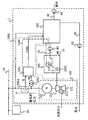
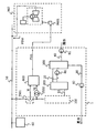
- FIG. 1 is a diagram showing an outline of the overall configuration of a first embodiment of a power generation / desalination system including a gas turbine power generation system according to the present invention
- FIG. 2 is a first embodiment of the power generation / desalination system according to the present invention.
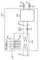
- FIG. 3 is the figure which showed the outline of the structure of the distillation system of 1st Embodiment of the electric power generation fresh water system of this invention
- FIG. 1 is a diagram showing an outline of the overall configuration of a first embodiment of a power generation / desalination system including a gas turbine power generation system according to the present invention
- FIG. 2 is a first embodiment of the power generation / desalination system according to the present invention.
- FIG. 3 is the figure which showed the outline of the structure of the distillation system of 1st Embodiment of the electric
- FIG. 5 is the active electric power and switch control signal of a hysteresis controller in 1st Embodiment of the electric power generation fresh water system of this invention
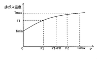
- FIG. 6 is a diagram showing the relationship between the active power and the exhaust gas temperature in the first embodiment of the power generation / desalination system of the present invention
- FIG. 7 is the power generation / desalination system of the present invention.
- FIG. 8 is a diagram showing an outline of the overall configuration of another aspect of the first embodiment of the power generation / desalination system of the present invention
- FIG. 9 is the first diagram of the power generation / desalination system of the present invention. It is the figure which showed the outline of the control algorithm of the controller of another aspect of embodiment of this invention.
- the power generation / desalination system 1 is roughly configured by a gas turbine power generation system 1000 that generates power and a water generation system 300 that obtains fresh water from seawater by distillation.
- the power system 50 associated with the power generation / desalination system 1 is a system to which power is supplied by the power generation / desalination system 1, and the power consumption system 60 whose power consumption fluctuates with time is linked to the power system 50.
- the gas turbine power generation system 1000 is generally configured by a power generation unit 100, a detector that detects power generated by a power generator in the power generation unit 100, and an exhaust gas temperature adjustment mechanism 1100.
- the power generation unit 100 includes a compressor (compressor) 121 that compresses air, a combustor 122 that mixes and burns compressed air and fuel generated by the compressor 121, and a gas turbine that is driven by combustion gas generated by the combustor 122. 123 and a generator 110.
- the power generation unit 100 receives natural gas, which is fuel, from a natural gas supply unit (not shown) and uses it as fuel for power generation.
- the generator 110 has a rotor that is mechanically connected to the shaft of the gas turbine 123, and generates power by driving the gas turbine 123.
- the power generation unit 100 is controlled by a gas turbine power generation controller (not shown) so that the voltage and frequency of the power system 50 are within a predetermined range. Be controlled.
- the control method of the gas turbine power generation system for the independent system can be based on a known method.
- a current sensor 5501 and a voltage sensor 5502 are provided at the output end of the generator 110 in order to detect the electrical output of the generator 110, that is, the generated power of the generator 110.
- Detection value Ig of current sensor 5501 and detection value Vg of voltage sensor 5502 are output to controller 600.
- the controller 600 calculates the active power of the generator 110 based on the detection values of the sensors 5501 and 5502 and outputs a load adjustment control signal CMD to the fresh water generation system 300.
- the current sensor 5501 and the voltage sensor 5502 constitute a detector that detects the electrical output output from the generator 110.
- the fresh water generation system 300 warms the seawater pumped by the pump 81 through the pipe 40 by the heat energy of the exhaust gas obtained from the power generation unit 100 and the heat energy of the electric heater 3005 generated by the power received from the power system 50. Fresh water is produced by an evaporation method in which water vapor is generated and the water vapor is cooled again.
- This fresh water generation system 300 is a heat exchanger that exchanges heat of high-pressure and high-temperature steam obtained from the exhaust heat recovery boiler 200 via the pipe 20 and heat obtained from the electric heater 3005 with high-pressure water in the pipe 3004. 3002, a pump 85 that circulates the hot water heat-exchanged by the heat exchanger 3002, and a distillation system 3003.
- the electric heater 3005 is linked to the three-phase power system 50 via the switch 3001. ON / OFF of the switch 3001 is controlled by the controller 600.
- the distillation system 3003 of the fresh water generation system 300 is roughly constituted by an evaporator 30031, an air cooler 30033, a pipe 30032, and a tank 30034.
- the evaporator 30031 stores the seawater pumped up by the pump 81 and heats the stored seawater with the heat energy of the high-pressure and high-temperature steam obtained by the heat exchanger 3002 to generate steam.
- the air cooler 30033 air-cools the water vapor generated by the evaporator 30031 transported via the pipe 30032 to generate fresh water.
- the tank 30034 temporarily stores fresh water obtained by air cooling by the air cooler 30033. Fresh water temporarily stored in the tank 30034 is supplied to consumers through the piping 30 by the pump 82 according to the water demand.
- an exhaust heat recovery boiler 200 includes a heat exchanger 2001 that exchanges heat of exhaust gas introduced from the power generation unit 100 through the exhaust gas conduit 10 with high-pressure water in the high-pressure water circulation pipe 20, and exhaust gas from outside air. And a high-pressure water circulation pipe 20 that circulates high-pressure water passing through the heat exchanger 2001. The high-temperature and high-pressure water heated by the heat exchanger 2001 is transported to the fresh water generation system 300 through the pipe 20 by the pump 80.
- the exhaust gas conduit 10 conveys the exhaust gas from the gas turbine 123 to the exhaust heat recovery boiler 200.
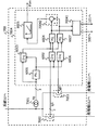
- phase calculator 6001 Based on the phase calculator 6001 for calculating the positive phase voltage phase and the phase information obtained by the phase calculator 6001 for calculating the active power of the output voltage at the electrical output of the generator 110.
- Dq converters 6002 and 6003 for calculating dq components of the output voltage and output current of the generator 110, an active power calculator 6004, and a hysteresis controller 6005 are provided.
- the active power calculator 6004 inputs the output values of the dq converters 6002 and 6003 and calculates the active power P of the generator 110.
- the calculated active power P is input to the hysteresis controller 6005.
- the hysteresis controller 6005 obtains a control signal CMD for controlling the switch 3001 from the input active power P and outputs it to the switch 3001.
- FIG. 5 shows the relationship between the active power P that is the input of the hysteresis controller 6005 and the switch control signal CMD that is the output.
- the hysteresis controller 6005 turns off the CMD as the output signal while the active power P drops from the rated output power Pmax of the power generation unit 100 to the predetermined value P1.
- the switch control signal CMD is switched on.
- the hysteresis controller 6005 switches the signal CMD on, the hysteresis controller 6005 fixes the signal CMD on even if the active power P rises, and the signal CMD is changed until the active power P becomes higher than the second predetermined value P2. turn on.
- the signal CMD is switched off.
- the second predetermined value P2 is set to be larger than the sum of the predetermined value P1 which is a reference for starting energization of the electric heater 3005 and the power consumption PR of the electric heater 3005.
- FIG. 6 shows the relationship between the active power P, the predetermined value P1, the second predetermined value P2, and the exhaust gas temperature.
- the exhaust gas temperature of the gas turbine 123 increases as the effective power P increases. Further, when the power consumption of the power consuming equipment 60 decreases, that is, when the active power P decreases, the exhaust gas temperature decreases, and when the power consumption increases, the exhaust gas temperature increases. It can be seen that a high thermal stress is generated in the exhaust gas conduit 10, the exhaust heat recovery boiler 200, and the like due to the temperature range and the repetition frequency.
- the operation waveform of each component of the present embodiment will be described with reference to FIG.
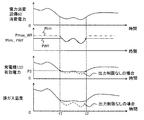
- the waveforms indicate, in order from the top, the power consumption of the power consumption facility 60, the control signal CMD of the switch 3001, the active power of the generator 110, and the exhaust gas temperature of the gas turbine 123.
- the controller 600 detects a reduction in the load on the generator 110, that is, the load on the gas turbine 123, and sends a control signal CMD to turn on the electric heater 3005. Turn it on. Since CMD is turned on, the power load becomes the power consumption facility 60 and the electric heater 3005, and the power consumption increases. In this case, since the power generation unit 100 increases the generated power to maintain the system frequency, the effective power increases to P1 + PR as a result. Thereafter, when the power consumption of the power consumption facility 60 increases and the effective power output from the generator 110 exceeds the second predetermined value P2 at time t2, the controller 600 turns off the control signal CMD.
- the exhaust gas temperature adjustment mechanism 1100 is roughly configured by the controller 600 and the electric heater 3005 of the fresh water generation system 300.
- the generator 110 detected using the current sensor 5501 and the voltage sensor 5502.
- the controller 600 outputs a switch control signal CMD for turning on the switch 3001 to the switch 3001 to supply power to the electric heater 3005 of the fresh water generation system 300.
- the exhaust gas temperature of the gas turbine generator decreases as the electrical output decreases.
- the exhaust gas temperature has a temperature difference of 300 ° C. due to electrical output. Therefore, when the electric load fluctuates with time, the exhaust gas temperature also fluctuates greatly, and the thermal stress in the exhaust gas conduit 10, the exhaust heat recovery boiler 200, etc. becomes excessive, which may lead to equipment failure.
- the exhaust gas temperature adjustment mechanism 1100 described above, electric power is supplied to the electric heater 3005 at a light load, and by increasing the power consumption given to the fresh water generation system 300, the amount of power generated by the generator 110 increases.
- the fluctuation range of the generated power of the generator 110 can be reduced. Therefore, the gas turbine 123 is operated so that the exhaust gas temperature becomes equal to or higher than the predetermined temperature, and the exhaust gas temperature is suppressed from becoming lower than the predetermined temperature. Therefore, even if the energy demand fluctuates, it is possible to prevent a large thermal stress from being generated in the exhaust gas conduit 10, the exhaust heat recovery boiler 200, and the like. Operates stably.
- fresh water fresh water
- seawater desalination technology such as seawater desalination that is used as domestic water such as drinking water or water for agricultural industry has attracted attention.
- the conventional fresh water generation system requires energy such as heat and electric power, and fossil fuel is generally used as the energy source. Therefore, there are restrictions on the energy source, and the fresh water generation cost is high.
- fossil fuels also need to be transported from the continent, making water production extremely expensive.
- a fresh water generation system based on the evaporation method normally obtains fresh water by warming seawater only by electric energy.
- the power generation unit 100 and the fresh water generation system 300 are connected to the exhaust gas conduit 10 and the exhaust heat. Connection is made via a recovery boiler 200.
- the efficiency of a gas turbine power generation system is about 40%, and most of the loss is discarded as thermal energy of exhaust gas.
- the power generation / desalination system 1 of the present embodiment that uses the heat energy of the exhaust gas for seawater heating, it is possible to produce water that effectively uses the heat discharged from the gas turbine 123, and the same amount of power and fresh water can be separately used.
- the heat of the heater 3005 is also exchanged by the heat exchanger 3002
- the heat generated by the heater 3005 can be used effectively, so that the water generation efficiency, particularly when the power consumption of the power consumption facility 60 is low, Efficiency can be improved and stable water production can be achieved at a lower cost.
- the energization control is facilitated by controlling on / off of energization to the electric heater 3005 by the switch 3001.
- the switch 3001 is turned on. Hunting, in which CMD on / off associated with subsequent increase in generated power is not stable, can be avoided, and the gas turbine power generation system 1000 can be stably operated.
- the electrical output of the generator 110 is directly detected by the current sensor 5501 and the voltage sensor 5502, but the method for detecting the electrical output of the generator 110 is not limited to this.
- Another aspect of the first embodiment will be described with reference to FIGS. 8 and 9.
- Another aspect of the first embodiment of the gas turbine power generation system, the power generation / desalination system, and the control method for the gas turbine power generation system according to the present invention is, for example, as shown in FIG. It is installed on the system 50 side.
- the controller 601 detects the power value Pg output to the power system 50 based on the detection signals Ig and Vg obtained by the current sensor 5501 and the voltage sensor 5502 as shown in FIG.
- a detector 6012 for calculating the power consumption Pheat in the electric heater 3005 based on the electric heater control signal CMD for Pg is provided.
- the sum of the power value Pg and the power consumption Pheat is used as an input to the hysteresis controller 6005.
- the electric switch 3001 since the electric switch 3001 operates with a predetermined delay time after issuing the opening / closing command, an error occurs if the effective power of the generator 110 is calculated using the electric heater control signal CMD as it is.
- the signal CMD is temporally delayed using a delay device 6011 that calculates a time delay corresponding to the operation delay time of the switch 3001 shown in FIGS.
- the power consumption Pheat in the electric heater is calculated from the output.
- the active power of the generator 110 is calculated, and the power consumption of the water generation system 300 is increased at light load. Therefore, it is possible to reduce the thermal stress of the exhaust gas conduit 10 and the exhaust heat recovery boiler 200 by avoiding a large decrease in the exhaust gas temperature, and it is possible to suppress the shortening of the equipment life and the equipment damage. Therefore, stable power generation and fresh water generation are possible.
- FIG. 10 is a diagram showing an outline of the overall configuration of the second embodiment of the power generation / desalination system according to the present invention
- FIG. 11 shows the control algorithm of the controller of the second embodiment of the power generation / desalination system according to the present invention.
- FIG. 12 is a schematic diagram, FIG.
- FIG. 12 is a diagram showing the relationship between the active power of the output limiter controller and the output limit value in the second embodiment of the power generation / desalination system of the present invention, and FIG.
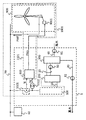
- FIG. 14 is the outline of the whole structure of the other aspect of 2nd Embodiment of the power generation desalination system of this invention.
- FIG. 15 is a diagram schematically showing the overall configuration of still another aspect of the second embodiment of the power generation / desalination system of the present invention.
- FIG. 16 is a diagram of the power generation / desalination system of the present invention. The figure which showed the outline of the whole structure of another aspect of 2nd Embodiment, A.
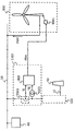
- a wind power generation facility 900 is linked to the power system 50 as an output-restrictable power source capable of limiting its output, Further, the controller 800 is configured to output a signal that limits the output of the wind power generation equipment 900.
- the current sensor 5501 and the voltage sensor 5502 detect the current and voltage of the generated power output from the generator 110 in the power generation unit 100, respectively.
- the controller 800 calculates the effective power of the generator 110 in the power generation unit 100 based on the detection values Ig and Vg detected by the current sensor 5001 and the voltage sensor 5002. Further, the controller 800 calculates an output reduction command to the wind power generation facility 900 based on the calculated effective power of the generator 110, and outputs an output restriction control signal Plim to the control device 9001 of the wind power generation facility 900.
- the control device 9001 of the wind power generation facility 900 receives the output restriction control signal Plim from the controller 800, and limits the generated power PWF in the wind power generation facility 900 to Plim or less.
- a method for limiting the generated power in the wind power generation facility 900 can be a known method.
- the controller 800 will be described in detail below with reference to FIG.
- the controller 800 calculates the active power of the output voltage of the electrical output of the generator 110, a phase calculator 8001 that calculates the positive voltage phase, and the generator based on the phase information obtained by the phase calculator 8001.
- Dq converters 8002 and 8003 for calculating dq components of output voltage and output current, an active power calculator 8004, and an output limiter calculator 8005 are provided.
- the active power calculator 8004 receives the output values of the dq converters 8002 and 8003 and calculates the active power P of the generator 110.
- the calculated active power calculation value P is output to the output limiter calculator 8005.
- the output limiter calculator 8005 calculates an output limit value Plim that is proportional to the active power calculation value P calculated by the active power calculator 8004, and outputs the calculation result Plim to the control device 9001 of the wind turbine generator 900.
- FIG. 12 shows the relationship between the active power calculation value P and the output limit value Plim calculated by the output limiter calculator 8005.
- the limit value Plim simply increases according to the value of the active power calculation value P when the active power calculation value P is equal to or less than a predetermined value P3 that is a reference for limiting the generated power PWF of the wind power generation equipment 900. Further, when the calculated active power P is larger than the predetermined value P3, the generated power PWF of the wind power generation facility 900 is set to be equal to the rated generated power Pmax_WF.
- the predetermined value P3 is set to a value smaller than the rated power output Pmax of the power generation unit 100.
- the output limit value Plim is set to the rated generated power Pmax_WF of the wind power generation facility 900, and the output of the wind power generation facility 900 is not limited. Further, when the active power calculation value P is equal to or less than the predetermined value P3, the output limit value Plim is set to a value equal to or less than the rated generated power Pmax_WF of the wind power generation facility 900, and the output of the wind power generation facility 900 is limited.
- FIG. 13 shows operation waveforms of each configuration of the present embodiment.
- the waveforms are the power consumption of the power consumption facility 60, the output power PWF and the output limit value Plim of the wind power generation facility 900, the effective power of the generator 110, and the exhaust gas temperature of the gas turbine 123 from the top.
- the output limit value Plim of the wind power generation facility 900 becomes smaller than the rated value Pmax_WF, and wind power The generated power PWF of the power generation facility 900 is limited. Thereafter, when the power consumption of the power consumption facility 60 increases and the active power output from the generator 110 exceeds the predetermined value P3 at time t2, the controller 600 makes the output limit value Plim equal to the rated value Pmax_WF.
- the exhaust gas temperature adjustment mechanism 1101 is roughly configured by the controller 800 and the wind power generation equipment 900. Configurations other than those described above are substantially the same as those of the gas turbine power generation system and power generation / desalination system of the first embodiment.
- the effective power of the generator 110 obtained using the current sensor 5501 and the voltage sensor 5502 is calculated.
- the controller 800 outputs to the control device 9001 an output limit value Plim that limits the amount of power generated by the wind power generation facility 900.
- the generated power PWF in the wind power generation facility 900 is limited, and the power generator 110 sharing ratio of the power supplied to the power consumption facility 60 is increased.
- the generated power of the generator 110 is increased by the limited power, and the gas turbine 123 is operated so that the exhaust gas temperature becomes equal to or higher than the predetermined temperature, so that the exhaust gas temperature becomes less than the predetermined temperature. . Therefore, even if the energy demand fluctuates, it is possible to prevent a large thermal stress from being generated in the exhaust gas conduit 10, the exhaust heat recovery boiler 200, and the like, and it is possible to suppress the shortening of the equipment life and the equipment damage, thereby stabilizing the system. It becomes possible to operate.
- the power generation unit 100 and the fresh water generation system 300 are connected via the exhaust gas conduit 10 and the exhaust heat recovery boiler 200, it is possible to produce fresh water that effectively uses the heat discharged from the gas turbine 123, and the inexpensive electric power. Supply and supply of fresh water become possible.
- the electric heater for supplying heat to the fresh water generation system 300 can be arbitrarily configured, and by not providing the electric heater, the main circuit configuration of the power generation fresh water generation system 1 can be simplified. Maintenance can be simplified and cost can be reduced.
- the active power calculation value P is unnecessarily necessary. Therefore, it is possible to generate power by both the wind power generation equipment 900 and the power generator 110, and thus it is possible to generate power at a lower cost.
- the effective power output from the generator 110 is calculated based on the output terminal voltage and output current of the generator 110, but the method for calculating the effective power output from the generator 110 is not limited to this.
- Another aspect of the second embodiment will be described with reference to FIG.
- Another aspect of the second embodiment of the gas turbine power generation system, power generation / desalination system, and control method of the gas turbine power generation system of the present invention is as shown in FIG.
- the output of the generator 110 is calculated from the difference from the generated power output from the power generation facility 900.
- the current Ig 1 supplied to the power consuming equipment 60 is detected by the current sensor 5503, the current Ig 2 supplied by the wind power generation equipment 900 is detected by the current sensor 5504, and each is output to the subtracter 850.
- the subtractor 850 subtracts the current Ig 2 from the input current Ig 1 to calculate a current value Ig that can be regarded as equivalent to the current output from the generator 110 and outputs the current value Ig to the controller 800.
- the controller 800 calculates the effective power of the generator 110 based on the voltage Vg detected by the voltage sensor 5502 and the current value Ig calculated by the subtractor 850, and calculates an output reduction command to the wind power generation facility 900.
- the output restriction control signal Plim is output to the control device 9001 of the wind power generation facility 900.
- the effective power of the generator 110 in the power generation unit 100 is calculated,
- the generated power PWF can be limited. Therefore, it is possible to reduce the thermal stress of the exhaust gas conduit 10 and the exhaust heat recovery boiler 200 by avoiding a large decrease in the exhaust gas temperature, and it is possible to suppress the shortening of the equipment life and the equipment damage. Therefore, stable power generation and fresh water generation are possible.
- FIG. 15 shows an aspect in which a photovoltaic power generation system 950 is provided as an output-restrictable power source
- FIG. 16 shows an aspect in which a biomass power generation system 960 is provided as an output-restrictable power source.
- the controller 800 calculates an output reduction command to the photovoltaic power generation system 950 based on the calculated effective power of the generator 110.
- the output restriction control signal Plim is output to the control device 9501 of the photovoltaic power generation system 950.
- the control device 9501 of the solar power generation system 950 receives the output restriction control signal Plim from the controller 800, and limits the generated power PS in the solar power generation system 950.
- the controller 800 calculates an output reduction command to the biomass power generation system 960 based on the calculated effective power of the generator 110, and the biomass
- the output restriction control signal Plim is output to the control device 9601 of the power generation system 960.
- the control device 9601 of the biomass power generation system 960 receives the output restriction control signal Plim from the controller 800, and limits the generated power PBM in the biomass power generation system 960.
- substantially the same effect as that of the second embodiment can be expected. Furthermore, when the biomass power generation system generates power with a gas engine, it can be expected that the output limiting speed is fast, and therefore, output limitation with higher accuracy than that of the wind power generation facility 900 can be expected.
- FIG. 17 is a diagram showing an outline of the overall configuration of the third embodiment of the power generation / desalination system of the present invention
- FIG. 18 shows the control algorithm of the controller of the third embodiment of the power generation / desalination system of the present invention.
- FIG. 19 is a diagram showing an outline, FIG.
- FIG. 19 is a diagram showing an outline of the entire configuration of another aspect of the third embodiment of the power generation / desalination system of the present invention
- FIG. 20 is a diagram of the power generation / desalination system according to the present invention. It is the figure which showed the outline of the control algorithm of the controller of the other aspect of 3 embodiment.
- the gas turbine power generation system 1000 includes one power generation unit, whereas the gas turbine power generation system 1002 according to the present embodiment includes two power generation units.
- the third embodiment details of the third embodiment will be described with reference to FIGS. 17 and 18.
- the third embodiment of the gas turbine power generation system, the power generation / desalination system, and the control method of the gas turbine power generation system includes two power generation units 100 and 101 that perform power generation by the gas turbine. .
- the power generation units 100 and 101 have the same structure.
- the power generation units 100 and 101 are connected to the power system 50 via the interconnection unit 700.
- the exhaust gas conduit 11 of the power generation unit 101 is connected to the exhaust heat recovery boiler 200 together with the exhaust gas conduit 10 of the power generation unit 100, and both exhaust gases of the power generation units 100 and 101 serve as a heat source for the exhaust heat recovery boiler 200.
- the configuration of the interconnecting unit 700 will be described with reference to FIG.
- the interconnection unit 700 includes a controller 7004 that calculates the output limit value Plim of the wind power generation system 900 and the balance control of the interconnection of the electrical main circuit and the power generation units 100 and 101.
- the interconnection unit 700 includes current sensors 7002 and 7003 for detecting the AC output currents of the generators 111 and 112, and the detected values ig0 and ig1 are input to the controller 7004.
- the controller 7004 detects the phase of the system voltage signal Vg detected by the voltage sensor 7001 by the phase calculator 6001 similarly to the controller 600 of the first embodiment, and the phase information is detected by the dq conversion detectors 6002, 6003. Output to 6006.
- the dq conversion detectors 6002 and 6006 perform dq conversion on the current detection values ig0 and ig1, and output the output signals to the active power calculators 6004 and 6007.
- the power calculators 6004 and 6007 calculate the effective power output from the generators 111 and 112 in the power generation units 100 and 101, respectively, from the dq conversion value of the system voltage and the outputs of the dq conversion detectors 6002 and 6003. .
- the calculated active power value is input to the adder 70042 and the balance detector 70041.
- the adder 70042 adds the calculated active power values of the generators 111 and 112 to calculate the effective power output by the two power generation units 100 and 101.
- the output limiter calculated value 8005 indicates the calculated effective power.
- the output limit value Plim is calculated.
- the balance detector 70041 calculates the ratio (output ratio) of the outputs of the generators 111 and 112 to the rated output, compares the two output ratios, and suppresses the output to the generator with the larger output ratio. Thus, an adjustment signal corresponding to the fuel adjustment amount of the gas turbine is transmitted.
- the adjustment signal is input to a power generation system controller (not shown), and the outputs of the power generation unit 100 and the power generation unit 101 are balanced. Note that the output of the generator with the smaller output ratio may be increased, and may be determined as appropriate according to the magnitude of the output ratio.
- the exhaust gas temperature adjustment mechanism 1102 is roughly configured by the controller 7004 and the wind power generation equipment 900 in the interconnection unit 700. Configurations other than those described above are substantially the same as those of the gas turbine power generation system and the power generation / desalination system of the first or second embodiment.
- the active power output from the generators 111 and 112 is calculated, and wind power generation is performed at light load.
- the generated power PWF at the facility 900 can be limited. Therefore, by avoiding a large decrease in the exhaust gas temperature of the gas turbine 123, it becomes possible to reduce the thermal stresses of the exhaust gas conduits 10, 11 and the exhaust heat recovery boiler 200, etc., shortening the equipment life and causing equipment damage. It is suppressed. Therefore, stable power generation and fresh water generation are possible.
- the output of the power generation unit 100 and the power generation unit 101 is balanced by including the balance detector 70041 that controls the electrical output of the two gas turbine generators to be balanced. Accordingly, the thermal stress applied to the exhaust gas conduits 10 and 11 can be equalized by suppressing the variation in the exhaust gas temperature, so that the thermal stress can be avoided from concentrating on the one exhaust gas conduit 10 or the exhaust gas conduit 11. Therefore, the life of the exhaust gas conduits 10 and 11 can be extended, and a more reliable high-output gas turbine power generation system and power generation / desalination system are provided.
- the configuration for limiting the output of the wind power generation system 900 is shown.
- the power consumption of the electric heater 3005 that includes the system unit 701 and supplies heat to the fresh water generation system 300 can be controlled.
- the interconnection unit 701 inputs the output of the adder 70042 to the hysteresis controller 6005, and the hysteresis controller 6005 in the controller 7014 in the interconnection unit 701 controls the control signal of the electric heater 3005.
- CMD is calculated. Also by such an aspect, the same effect as that of the third embodiment can be obtained.
- the aspect in which the structures of the power generation units 100 and 101 are equal is illustrated, but when the rated capacity of the generators of the plurality of power generation units is different, the ratio of the output power to the rated capacity of the plurality of power generation units (The correction signal may be generated by the balance detector 70041 so that the output ratios are equal to each other. Also by such an aspect, the same effect as that of the third embodiment can be obtained.
- an exhaust gas temperature adjusting mechanism having a communication port that calculates the effective power of the generator 110 and transmits an output limit value Plim for limiting the output of the wind power generation equipment 900 to the control device 9001 of the wind power generation equipment 900.
- the target for consuming electric power at a light load when the active power is a predetermined value P1 or less is the electricity of the water generation system 300.
- the heater 3005 for example, there is a motor drive system that drives a pump 81 that pumps seawater into the evaporator 30031. By actively driving the motor drive system at light loads, the fluctuation range of the generated power of the generator 110 of the power generation unit 100 can be reduced, and highly reliable and inexpensive power supply and fresh water supply are possible. It becomes.
- Wind power generation facilities 9001, 9501, 9601 ... control device, 950 ... Solar power generation system, 960 ... Biomass power generation system, 1000, 1001, 1002 ... gas turbine power generation system, 1100, 1101, 1102, 1103 ... Exhaust gas temperature adjustment mechanism.
Landscapes
- Engineering & Computer Science (AREA)
- Mechanical Engineering (AREA)
- General Engineering & Computer Science (AREA)
- Chemical & Material Sciences (AREA)
- Combustion & Propulsion (AREA)
- Power Engineering (AREA)
- Control Of Eletrric Generators (AREA)
Description
本発明は、ガスタービン発電システムおよびそれを備えた発電造水システム、ならびにガスタービン発電システムの制御方法に関する。
タービン設備と水製造設備を備えたタービンシステムにおいて、ガスタービン設備、ガスタービン設備からの排気ガスを熱源として蒸気を生成する排熱回収型の蒸気生成設備、この蒸気生成設備からの蒸気により回転動力を得る蒸気タービン設備、および蒸気生成設備からの蒸気を利用して原水(例えば海水や工業用水等)を蒸留して純水を得る水製造設備を備えているものがある(特許文献1参照)。
例えば離島や砂漠地帯等に設置して1つのプラントでエネルギ(電力や動力等)と水とを得ようとすると、水については貯留できるのでストックがある限りプラントの運転状況に関わらず供給可能なのに対し、エネルギは性質上保存することができない。
ガスタービン発電システムにより電力を供給される電力系統には、時間的に消費電力の変動する電力消費設備が必ず連係している。
ここで、ガスタービン発電システムのガスタービンの排ガス温度は、発電機に供給する機械的エネルギ[kW]に対して単調増加の特性を有している。従って、電力消費設備での消費電力に排ガス温度は単調増加の特性を有していると言うことができる。
例えば、電力消費設備での消費電力が少ない場合とガスタービンシステムの定格発電時では、排ガス温度に百度を上回る温度差が生じることがある。
例えば、電力消費設備での消費電力が少ない場合とガスタービンシステムの定格発電時では、排ガス温度に百度を上回る温度差が生じることがある。
このような大きな排ガス温度の変化は、排ガス導管等に大きな熱応力を発生させ、機器寿命の短縮や機器損傷を起こし得る。
従って、エネルギと水の供給に上記従来技術を適用した場合、エネルギ需要が変動する際に排ガス導管等にダメージが加わり、システムの安定稼働が困難となる恐れがある。
このように安定して稼働できない場合、造水にも影響が及ぶため、安定して発電を継続することが求められる。
このように安定して稼働できない場合、造水にも影響が及ぶため、安定して発電を継続することが求められる。
本発明は、上記の事情に鑑みてなされたものであり、ガスタービンからの排ガス温度の変動を小さくすることで、排ガス導管等へのダメージを低減することが可能なガスタービン発電システムと、このようなガスタービン発電システムを備えた発電造水システム、ならびにガスタービン発電システムの制御方法を提供することを目的とする。
上記目的を達成するために、本発明は、ガスタービン発電システム(1000,1001,1002)であって、空気を圧縮する圧縮機(121)と、この圧縮機で生成した圧縮空気と燃料を混合して燃焼する燃焼器(122)と、この燃焼器で生成した燃焼ガスにより駆動するガスタービン(123)と、このガスタービンの駆動によって発電する発電機(110,111,112)とを有した発電ユニット(100,101)と、前記発電機の出力する電気的出力を検出する検出器(5501,5502,5503,5504,7001,7002,7003)と、この検出器で検出された前記発電機の電気的出力から前記発電機の有効電力を求め、この求めた有効電力が所定値以下となるときは、前記ガスタービンの排ガス温度が所定温度未満とならないように調整する排ガス温度調整機構(1100,1101,1102)とを備えたことを特徴とする。
本発明によれば、排ガス温度調整機構によってガスタービンからの排ガス温度の変動を小さくすることができ、排ガス導管等へのダメージを低減することが可能となる。したがって、ガスタービン発電システムを安定して稼働することができ、例えば造水を伴う発電造水システムに好適なガスタービン発電システムおよびその制御方法が提供される。
以下に本発明のガスタービン発電システムおよび発電造水システム、ならびにガスタービン発電システムの制御方法の実施形態を、図面を用いて説明する。
<第1の実施形態>
本発明のガスタービン発電システムおよび発電造水システム、ならびにガスタービン発電システムの制御方法の第1の実施形態を、図1乃至図9を用いて説明する。
図1は、本発明のガスタービン発電システムを備えた発電造水システムの第1の実施形態の全体構成の概略を示した図、図2は、本発明の発電造水システムの第1の実施形態の造水システムの構成の概略を示した図、図3は、本発明の発電造水システムの第1の実施形態の蒸留システムの構成の概略を示した図、図4は、本発明の発電造水システムの第1の実施形態のコントローラの制御アルゴリズムの概略を示した図、図5は、本発明の発電造水システムの第1の実施形態におけるヒステリシス制御器の有効電力とスイッチ制御信号との関係を示した図、図6は、本発明の発電造水システムの第1の実施形態における有効電力と排ガス温度との関係を示した図、図7は、本発明の発電造水システムの第1の実施形態の各構成の動作波形の一例を示した図、図8は、本発明の発電造水システムの第1の実施形態の別の態様の全体構成の概略を示した図、図9は、本発明の発電造水システムの第1の実施形態の別の態様のコントローラの制御アルゴリズムの概略を示した図、である。
本発明のガスタービン発電システムおよび発電造水システム、ならびにガスタービン発電システムの制御方法の第1の実施形態を、図1乃至図9を用いて説明する。
図1は、本発明のガスタービン発電システムを備えた発電造水システムの第1の実施形態の全体構成の概略を示した図、図2は、本発明の発電造水システムの第1の実施形態の造水システムの構成の概略を示した図、図3は、本発明の発電造水システムの第1の実施形態の蒸留システムの構成の概略を示した図、図4は、本発明の発電造水システムの第1の実施形態のコントローラの制御アルゴリズムの概略を示した図、図5は、本発明の発電造水システムの第1の実施形態におけるヒステリシス制御器の有効電力とスイッチ制御信号との関係を示した図、図6は、本発明の発電造水システムの第1の実施形態における有効電力と排ガス温度との関係を示した図、図7は、本発明の発電造水システムの第1の実施形態の各構成の動作波形の一例を示した図、図8は、本発明の発電造水システムの第1の実施形態の別の態様の全体構成の概略を示した図、図9は、本発明の発電造水システムの第1の実施形態の別の態様のコントローラの制御アルゴリズムの概略を示した図、である。
図1において、発電造水システム1は、大きくは、発電を行うガスタービン発電システム1000と、蒸留により海水から真水を得る造水システム300とにより概略構成されている。
まず電力系統50の構成について説明する。
発電造水システム1の連係する電力系統50は、発電造水システム1により電力を供給される系統であり、この電力系統50には時間的に消費電力の変動する電力消費設備60が連係する。
発電造水システム1の連係する電力系統50は、発電造水システム1により電力を供給される系統であり、この電力系統50には時間的に消費電力の変動する電力消費設備60が連係する。
次に、ガスタービン発電システム1000の構成について説明する。
ガスタービン発電システム1000は、発電ユニット100と、この発電ユニット100内の発電機の発電する発電電力を検出する検出器と、排ガス温度調整機構1100とにより概略構成される。
ガスタービン発電システム1000は、発電ユニット100と、この発電ユニット100内の発電機の発電する発電電力を検出する検出器と、排ガス温度調整機構1100とにより概略構成される。
発電ユニット100は、空気を圧縮するコンプレッサ(圧縮機)121と、コンプレッサ121で生成した圧縮空気と燃料を混合して燃焼する燃焼器122と、燃焼器122で生成した燃焼ガスにより駆動するガスタービン123と、発電機110とにより概略構成される。発電ユニット100は、図示しない天然ガス供給部より燃料である天然ガスを入力し、発電のための燃料とする。
発電機110は、ガスタービン123の軸に機械的に接続された回転子を有しており、ガスタービン123の駆動によって発電する。
発電機110は、ガスタービン123の軸に機械的に接続された回転子を有しており、ガスタービン123の駆動によって発電する。
電力系統50に連係する電源は発電造水システム1のみの独立系統であるため、電力系統50の電圧や周波数を所定の範囲内に収めるように、発電ユニット100は図示しないガスタービン発電制御器により制御される。独立系統用のガスタービン発電システムの制御方法は、公知の方法によることができる。
発電機110の出力端には、発電機110の電気的出力、つまり発電機110の発電電力を検出するために、電流センサ5501および電圧センサ5502が備えられている。電流センサ5501の検出値Igおよび電圧センサ5502の検出値Vgはコントローラ600に出力される。コントローラ600は、センサ5501,5502での検出値を基に発電機110の有効電力を算出し、造水システム300へ負荷調整用制御信号CMDを出力する。
電流センサ5501と電圧センサ5502とにより、発電機110の出力する電気的出力を検出する検出器は構成される。
電流センサ5501と電圧センサ5502とにより、発電機110の出力する電気的出力を検出する検出器は構成される。
次に、発電造水システム1における造水システム300の構成を、図2を用いて説明する。
造水システム300は、発電ユニット100から得る排ガスの熱エネルギと電力系統50より受電する電力によって発熱した電気ヒータ3005の熱エネルギとにより、ポンプ81により配管40を介して汲み上げられた海水を温めて水蒸気を発生させ、この水蒸気を再び冷却する蒸発法により真水を製造する。
この造水システム300は、配管20を介して排熱回収ボイラ200より得られる高圧高温水蒸気の熱と電気ヒータ3005から得られる熱とを配管3004内の高圧水に対して熱交換する熱交換器3002と、この熱交換器3002で熱交換された温水を循環するポンプ85と、蒸留システム3003とにより概略構成される。
この造水システム300は、配管20を介して排熱回収ボイラ200より得られる高圧高温水蒸気の熱と電気ヒータ3005から得られる熱とを配管3004内の高圧水に対して熱交換する熱交換器3002と、この熱交換器3002で熱交換された温水を循環するポンプ85と、蒸留システム3003とにより概略構成される。
電気ヒータ3005は、スイッチ3001を介して3相の電力系統50に連係する。スイッチ3001のON、OFFはコントローラ600により制御される。
造水システム300の蒸留システム3003の構成を、図3を用いて説明する。
図3において、蒸留システム3003は、蒸発器30031、風冷機30033、配管30032、タンク30034により概略構成される。
蒸発器30031は、ポンプ81により汲み上げられた海水を蓄えるとともに、熱交換器3002によって得られた高圧高温水蒸気の有する熱エネルギにより、この蓄えた海水を加熱して水蒸気を生成する。風冷器30033は、配管30032を介して輸送された蒸発器30031で生成された水蒸気を空冷して真水を生成する。タンク30034は、風冷器30033による空冷で得られた真水を一時的に蓄える。タンク30034に一時蓄えられた真水は、水需要に応じてポンプ82により配管30を介して需要家に供給される。
図3において、蒸留システム3003は、蒸発器30031、風冷機30033、配管30032、タンク30034により概略構成される。
蒸発器30031は、ポンプ81により汲み上げられた海水を蓄えるとともに、熱交換器3002によって得られた高圧高温水蒸気の有する熱エネルギにより、この蓄えた海水を加熱して水蒸気を生成する。風冷器30033は、配管30032を介して輸送された蒸発器30031で生成された水蒸気を空冷して真水を生成する。タンク30034は、風冷器30033による空冷で得られた真水を一時的に蓄える。タンク30034に一時蓄えられた真水は、水需要に応じてポンプ82により配管30を介して需要家に供給される。
排熱回収ボイラ200の構成について、図1を用いて説明する。
図1において、排熱回収ボイラ200は、排ガス導管10によって発電ユニット100より導入された排ガスの熱を高圧水循環配管20内の高圧の水に対して熱交換する熱交換器2001と、排ガスを外気に放出する経路15と、熱交換器2001を通過する高圧の水を循環させる高圧水循環配管20を備えている。熱交換器2001によって加熱した高温高圧の水をポンプ80により配管20を介して造水システム300に運搬する。
排ガス導管10は、ガスタービン123の排ガスを排熱回収ボイラ200に運搬する。
コントローラ600の構成、およびスイッチ3001の制御アルゴリズムについて、図4を用いて説明する。
コントローラ600は、発電機110の電気的出力における出力電圧の有効電力を算出するための、正相電圧位相を算出する位相算出器6001と、この位相算出器6001により得られた位相情報を基に発電機110の出力電圧および出力電流のd-q成分を算出するd-q変換器6002,6003と、有効電力算出器6004と、ヒステリシス制御器6005とを備える。
有効電力算出器6004は、d-q変換器6002,6003の出力値を入力して発電機110の有効電力Pを算出する。算出された有効電力Pは、ヒステリシス制御器6005に入力される。ヒステリシス制御器6005は、入力された有効電力Pよりスイッチ3001を制御する制御信号CMDを求め、スイッチ3001に出力する。
ヒステリシス制御器6005の入力である有効電力Pと、出力であるスイッチ制御信号CMDの関係を図5に示す。
ヒステリシス制御器6005は、有効電力Pが発電ユニット100の定格出力電力Pmaxから所定の値P1まで下がる間は、出力信号であるCMDはオフとする。有効電力PがP1より小さくなった場合、スイッチ制御信号CMDをオンに切り替える。
また、ヒステリシス制御器6005は、一度、信号CMDをオンに切り替えたら、有効電力Pが上昇しても信号CMDをオンに固定し、有効電力Pが第2所定値P2より高くなるまで信号CMDをオンにする。そして有効電力Pが第2所定値P2より高くなった場合に信号CMDをオフに切り替える。この第2所定値P2は、電気ヒータ3005に通電を開始する基準である所定値P1と電気ヒータ3005の消費電力PRの和より大きくなるように設定する。
有効電力P、所定値P1、第2所定値P2、および排ガス温度の関係を図6に示す。
図6に示すように、ガスタービン123の排ガス温度は、有効電力Pが増加するにつれて高くなる。
また、電力消費設備60の消費電力が少なくなった場合、つまり有効電力Pが小さくなった場合は、排ガス温度は下がり、消費電力が大きくなった場合には排ガス温度は高くなる。この温度幅および繰り返し頻度により、排ガス導管10や排熱回収ボイラ200等に高い熱応力が発生することが分かる。
また、電力消費設備60の消費電力が少なくなった場合、つまり有効電力Pが小さくなった場合は、排ガス温度は下がり、消費電力が大きくなった場合には排ガス温度は高くなる。この温度幅および繰り返し頻度により、排ガス導管10や排熱回収ボイラ200等に高い熱応力が発生することが分かる。
本実施形態の各構成の動作波形を、図7を用いて説明する。波形は、上から順に、電力消費設備60の消費電力、スイッチ3001の制御信号CMD、発電機110の有効電力、そしてガスタービン123の排ガス温度を示している。
時刻t1において、電力消費設備60の消費電力がP1を下回ると、コントローラ600は発電機110の負荷、すなわちガスタービン123の負荷の低減を検出し、電気ヒータ3005を投入させるために制御信号CMDをONにする。
CMDがONになったため、電力負荷は電力消費設備60と電気ヒータ3005となり、消費電力が増える。
この場合、発電ユニット100は系統の周波数を維持させるため発電電力を増加させるため、結果的に有効電力がP1+PRまで増加する。
その後、電力消費設備60の消費電力が増加し、発電機110の出力する有効電力が時刻t2において第2所定値P2を超えたとき、コントローラ600は制御信号CMDをオフにする。
CMDがONになったため、電力負荷は電力消費設備60と電気ヒータ3005となり、消費電力が増える。
この場合、発電ユニット100は系統の周波数を維持させるため発電電力を増加させるため、結果的に有効電力がP1+PRまで増加する。
その後、電力消費設備60の消費電力が増加し、発電機110の出力する有効電力が時刻t2において第2所定値P2を超えたとき、コントローラ600は制御信号CMDをオフにする。
本実施形態においては、コントローラ600と造水システム300の電気ヒータ3005とにより、排ガス温度調整機構1100は概略構成される。
上述した本発明のガスタービン発電システムおよび発電造水システム、ならびにガスタービン発電システムの制御方法の第1の実施形態によれば、電流センサ5501と電圧センサ5502とを用いて検出される発電機110の有効電力が所定値P1以下となる軽負荷時には、コントローラ600は、造水システム300の電気ヒータ3005に電力を供給するためにスイッチ3001をオンにするスイッチ制御信号CMDをスイッチ3001に出力する。
上述のように、ガスタービン発電機の排ガス温度は電気的出力が減少すると排ガス温度も低下する。ガスタービン発電機によっては、排ガス温度は電気的出力により300℃の温度差が生じる例もある。従って、電気的負荷が時間的に変動する場合、排ガス温度も大きく変動し、排ガス導管10や排熱回収ボイラ200等での熱応力が過大になり、装置故障を招く可能性がある。
しかし、上述の排ガス温度調整機構1100を備えることにより、軽負荷時には電気ヒータ3005に電力が供給され、造水システム300に与える消費電力を増加させることにより、発電機110での発電量が増加し、発電機110の発電電力の変動幅を低減することができる。よって排ガス温度が所定温度以上となるようにガスタービン123は稼働し、排ガス温度が所定温度未満となることが抑制される。従って、エネルギ需要が変動したとしても排ガス導管10や排熱回収ボイラ200等に大きな熱応力が発生することが防止され、機器寿命の短縮や機器損傷することが抑制されて、ガスタービン発電システム1000が安定して稼働する。
また、近年、世界的な人口増加や気候変動により、水不足が深刻化しつつあり、水資源の確保が重要な課題となっている。こうした状況から、例えば海水から淡水(真水)を造水し、飲料水などの生活用水や農工業用水として利用する海水淡水化などの造水技術が注目されている。特に、離島においては上記水資源の確保のほか、安定した電力供給に対する需要がある。
従来の造水システムでは、熱や電力などのエネルギが必要であり、そのエネルギ源として、一般的には化石燃料が使用されている。そのため、エネルギ源の制約があり、造水コストも高い。離島においては、化石燃料も大陸より輸送する必要があり、造水が極めて高コストになる。
従来の造水システムでは、熱や電力などのエネルギが必要であり、そのエネルギ源として、一般的には化石燃料が使用されている。そのため、エネルギ源の制約があり、造水コストも高い。離島においては、化石燃料も大陸より輸送する必要があり、造水が極めて高コストになる。
蒸発法による造水システムは、通常は電気エネルギのみにより海水を温めることで真水を得るが、本実施形態の発電造水システムでは、発電ユニット100と造水システム300を、排ガス導管10および排熱回収ボイラ200を介して接続している。
通常、ガスタービン発電システムの効率は、約40%であり、損失分の多くは排ガスの熱エネルギとして廃棄される。しかしこの排ガスの熱エネルギを海水加熱に用いる本実施形態の発電造水システム1によれば、ガスタービン123の排出する熱を有効活用した造水が可能となり、同じ量の電力と造水を個別に実施する場合に比べ、天然ガス消費量を格段に低減することができ、安価な電力供給と真水の供給が可能となる。また、コントローラ600と電気ヒータ3005とにより、排ガス温度が所定値未満とならないようにコントロールしているため、排ガス温度調整が可能となり、発電造水システムの高信頼化が図れる。よって安定した発電および造水が可能であり、電力および水の安定供給に大きく寄与する。
通常、ガスタービン発電システムの効率は、約40%であり、損失分の多くは排ガスの熱エネルギとして廃棄される。しかしこの排ガスの熱エネルギを海水加熱に用いる本実施形態の発電造水システム1によれば、ガスタービン123の排出する熱を有効活用した造水が可能となり、同じ量の電力と造水を個別に実施する場合に比べ、天然ガス消費量を格段に低減することができ、安価な電力供給と真水の供給が可能となる。また、コントローラ600と電気ヒータ3005とにより、排ガス温度が所定値未満とならないようにコントロールしているため、排ガス温度調整が可能となり、発電造水システムの高信頼化が図れる。よって安定した発電および造水が可能であり、電力および水の安定供給に大きく寄与する。
また、ヒータ3005の熱も熱交換機3002によって熱交換することにより、ヒータ3005の発する熱を有効に利用することができるため、造水効率、特に電力消費設備60の消費電力の少ないときの造水効率の向上を図ることができ、より低コストで安定した造水が可能となる。
更に、図5に示すように、ヒータ3005の出力を発電機110の発電電力に応じて変更することにより、運転状態に応じた柔軟な運用が実現できる。
また、スイッチ3001により電気ヒータ3005への通電のオン、オフを制御することにより、通電制御が容易となる。
更に、スイッチ3001の切替を決める第2所定値P2を、電気ヒータ3005に通電する基準である所定値P1と電気ヒータ3005の消費電力PRの和より大きくなるように設定することで、スイッチ3001投入後の発電電力増加に伴うCMDのオンオフが安定しないハンチングを回避することができ、ガスタービン発電システム1000の安定的な運用が可能となる。
なお、本実施形態では、発電機110の電気的出力を電流センサ5501・電圧センサ5502によって直接検出したが、発電機110の電気的出力の検出方法はこれに限定されない。以下、第1の実施形態の別の態様について図8および図9を用いて説明する。
本発明のガスタービン発電システムおよび発電造水システム、ならびにガスタービン発電システムの制御方法の第1の実施形態の別の態様は、例えば図8に示すように、電流センサ5501および電圧センサ5502が電力系統50側に設置されたものである。
このとき、コントローラ601は、図9に示すように、電流センサ5501および電圧センサ5502により得た検出信号Ig,Vgを基にして、電力系統50に出力される電力値Pgを検出し、電力値Pgを電気ヒータ制御信号CMDを基に電気ヒータ3005での消費電力Pheatを計算する検出器6012を備えている。また電力値Pgと消費電力Pheatの和をヒステリシス制御器6005の入力とする。
更に、一般的に、電気スイッチ3001は開閉指令を出してから所定の遅れ時間を伴って作動するため、電気ヒータ制御信号CMDをそのまま用いて発電機110の有効電力を算出すると、誤差が生じる。本誤差の解消のため、図8および図9で示すスイッチ3001の作動遅れ時間相当の時間遅れをコントローラ601内で算出する遅延器6011を用いて信号CMDを時間的に遅延させ、遅延器6011の出力から電気ヒータでの消費電力Pheatを算出する。
本発明のガスタービン発電システムおよび発電造水システム、ならびにガスタービン発電システムの制御方法の第1の実施形態の別の態様は、例えば図8に示すように、電流センサ5501および電圧センサ5502が電力系統50側に設置されたものである。
このとき、コントローラ601は、図9に示すように、電流センサ5501および電圧センサ5502により得た検出信号Ig,Vgを基にして、電力系統50に出力される電力値Pgを検出し、電力値Pgを電気ヒータ制御信号CMDを基に電気ヒータ3005での消費電力Pheatを計算する検出器6012を備えている。また電力値Pgと消費電力Pheatの和をヒステリシス制御器6005の入力とする。
更に、一般的に、電気スイッチ3001は開閉指令を出してから所定の遅れ時間を伴って作動するため、電気ヒータ制御信号CMDをそのまま用いて発電機110の有効電力を算出すると、誤差が生じる。本誤差の解消のため、図8および図9で示すスイッチ3001の作動遅れ時間相当の時間遅れをコントローラ601内で算出する遅延器6011を用いて信号CMDを時間的に遅延させ、遅延器6011の出力から電気ヒータでの消費電力Pheatを算出する。
このような態様のガスタービン発電システムおよび発電造水システム、ならびにガスタービン発電システムの制御方法においても、発電機110の有効電力を算出し、軽負荷時には造水システム300の消費電力を増加させる。よって、排ガス温度の大きな低下を回避することで、排ガス導管10や排熱回収ボイラ200の熱応力を低減することが可能となり、機器寿命の短縮や機器損傷することも抑制される。従って、安定した発電および造水が可能である。
<第2の実施形態>
本発明のガスタービン発電システムおよび発電造水システム、ならびにガスタービン発電システムの制御方法の第2の実施形態を図10乃至図16を用いて説明する。
第2の実施形態の説明において、第1の実施形態と同一の要素については同一の符号を用い、説明は省略する。
図10は、本発明の発電造水システムの第2の実施形態の全体構成の概略を示した図、図11は、本発明の発電造水システムの第2の実施形態のコントローラの制御アルゴリズムの概略を示した図、図12は、本発明の発電造水システムの第2の実施形態における出力リミッタ制御器の有効電力と出力リミット値との関係を示した図、図13は、本発明の発電造水システムの第2の実施形態の各構成の動作波形の一例を示した図、図14は、本発明の発電造水システムの第2の実施形態の他の態様の全体構成の概略を示した図、図15は、本発明の発電造水システムの第2の実施形態の更に別の他の態様の全体構成の概略を示した図、図16は、本発明の発電造水システムの第2の実施形態の更に別の他の態様の全体構成の概略を示した図、である。
本発明のガスタービン発電システムおよび発電造水システム、ならびにガスタービン発電システムの制御方法の第2の実施形態を図10乃至図16を用いて説明する。
第2の実施形態の説明において、第1の実施形態と同一の要素については同一の符号を用い、説明は省略する。
図10は、本発明の発電造水システムの第2の実施形態の全体構成の概略を示した図、図11は、本発明の発電造水システムの第2の実施形態のコントローラの制御アルゴリズムの概略を示した図、図12は、本発明の発電造水システムの第2の実施形態における出力リミッタ制御器の有効電力と出力リミット値との関係を示した図、図13は、本発明の発電造水システムの第2の実施形態の各構成の動作波形の一例を示した図、図14は、本発明の発電造水システムの第2の実施形態の他の態様の全体構成の概略を示した図、図15は、本発明の発電造水システムの第2の実施形態の更に別の他の態様の全体構成の概略を示した図、図16は、本発明の発電造水システムの第2の実施形態の更に別の他の態様の全体構成の概略を示した図、である。
第1実施形態では、電力系統50における電力消費設備60の電力消費量が小さい状態である発電機110の負荷が軽い場合は、発電造水システム1内の電気ヒータ3005をONすることにより発電機110の負荷を重くすることで排ガス温度を調整していた。
これに対し、本実施形態のガスタービン発電システム1001では、発電機110の負荷が軽い場合は、風力発電設備900の発電電力を減らすことにより発電ユニット100における発電機110の負荷を増加させ、排ガス温度の低下を抑制する。
以下、図10乃至図13を用いて、第2の実施形態の詳細を説明する。
これに対し、本実施形態のガスタービン発電システム1001では、発電機110の負荷が軽い場合は、風力発電設備900の発電電力を減らすことにより発電ユニット100における発電機110の負荷を増加させ、排ガス温度の低下を抑制する。
以下、図10乃至図13を用いて、第2の実施形態の詳細を説明する。
図10において、本発明のガスタービン発電システムおよび発電造水システムの第2の実施形態は、電力系統50に、その出力を制限することができる出力制限可能電源として風力発電設備900が連係され、またコントローラ800が風力発電設備900の出力を制限する信号を出力する構成となっている。
電流センサ5501および電圧センサ5502は、発電ユニット100における発電機110の出力する発電電力の電流および電圧をそれぞれ検出する。
コントローラ800は、電流センサ5001、電圧センサ5002により検出した検出値Ig,Vgを基にして発電ユニット100における発電機110の有効電力を算出する。
また、コントローラ800は、算出した発電機110の有効電力を基にして、風力発電設備900への出力低下指令を算出し、風力発電設備900の制御装置9001に出力制限制御信号Plimを出力する。
また、コントローラ800は、算出した発電機110の有効電力を基にして、風力発電設備900への出力低下指令を算出し、風力発電設備900の制御装置9001に出力制限制御信号Plimを出力する。
風力発電設備900の制御装置9001は、コントローラ800より出力制限制御信号Plimを受信し、風力発電設備900での発電電力PWFをPlim以下に制限する。この風力発電設備900での発電電力制限方法については、公知の方法によることができる。
コントローラ800について、以下図11を用いて詳細に説明する。
コントローラ800は、発電機110の電気的出力の出力電圧の有効電力を算出するため、正電圧位相を算出する位相算出器8001と、この位相算出器8001により得られた位相情報を基に発電機出力電圧および出力電流のd-q成分を算出するd-q変換器8002,8003と、有効電力算出器8004と、出力リミッタ算出器8005とを備える。
有効電力算出器8004は、d-q変換器8002,8003の出力値を入力して発電機110の有効電力Pを算出する。算出された有効電力算出値Pは、出力リミッタ算出器8005に出力される。
出力リミッタ算出器8005は、有効電力算出器8004で算出された有効電力算出値Pに比例した出力リミット値Plimを算出し、この算出結果Plimを風力発電設備900の制御装置9001に出力する。
出力リミッタ算出器8005は、有効電力算出器8004で算出された有効電力算出値Pに比例した出力リミット値Plimを算出し、この算出結果Plimを風力発電設備900の制御装置9001に出力する。
出力リミッタ算出器8005で算出する、有効電力算出値Pと出力リミット値Plimの関係を図12に示す。
リミット値Plimは、有効電力算出値Pが風力発電設備900の発電電力PWFを制限する基準である所定値P3以下のときは、有効電力算出値Pの値に応じて単純に増加する。また、有効電力算出値Pが所定値P3より大きいときは、風力発電設備900の発電電力PWFが定格発電電力Pmax_WFと等しくなるよう設定されている。所定値P3は、発電ユニット100の定格電力出力Pmaxより小さい値に設定されている。つまり、有効電力算出値Pが所定値P3よりも大きいときには、出力リミット値Plimは風力発電設備900の定格発電電力Pmax_WFに設定されて風力発電設備900の出力が制限されない。また、有効電力算出値Pが所定値P3以下のときは、出力リミット値Plimは風力発電設備900の定格発電電力Pmax_WF以下の値に設定され、風力発電設備900の出力が制限される。
本実施形態の各構成の動作波形を図13に示す。
波形は、上段より電力消費設備60の消費電力、風力発電設備900の出力電力PWFと出力制限値Plim、発電機110の有効電力、そしてガスタービン123の排ガス温度である。
電力消費設備60の消費電力が減少して、発電機110の有効電力が所定値P3より小さくなった時刻t1において、風力発電設備900の出力リミット値Plimが定格値であるPmax_WFより小さくなり、風力発電設備900の発電電力PWFが制限される。
その後、電力消費設備60の消費電力が増加し、発電機110の出力する有効電力が時刻t2において所定値P3を超えたとき、コントローラ600は出力リミット値Plimが定格値であるPmax_WFと等しくする。
その後、電力消費設備60の消費電力が増加し、発電機110の出力する有効電力が時刻t2において所定値P3を超えたとき、コントローラ600は出力リミット値Plimが定格値であるPmax_WFと等しくする。
本実施形態においては、コントローラ800と風力発電設備900とにより、排ガス温度調整機構1101は概略構成される。
上述した以外の構成は第1の実施形態のガスタービン発電システムおよび発電造水システムと略同じである。
上述した以外の構成は第1の実施形態のガスタービン発電システムおよび発電造水システムと略同じである。
本発明のガスタービン発電システムおよび発電造水システム、ならびにガスタービン発電システムの制御方法の第2の実施形態では、電流センサ5501と電圧センサ5502とを用いて求められた発電機110の有効電力が所定値P3以下となる軽負荷時には、コントローラ800は、風力発電設備900の発電量を制限する値の出力リミット値Plimを制御装置9001に出力する。これにより、風力発電設備900での発電電力PWFが制限され、電力消費設備60に供給する電力の発電機110分担割合が高くなる。このため、制限された電力分だけ発電機110の発電電力が増加し、排ガス温度が所定温度以上となるようにガスタービン123が稼働して、排ガス温度が所定温度未満となることが抑制される。よって、エネルギ需要が変動したとしても排ガス導管10や排熱回収ボイラ200等に大きな熱応力が発生することが防止され、機器寿命の短縮や機器損傷することが抑制されて、システムが安定して稼働することが可能となる。
また、発電ユニット100と造水システム300を、排ガス導管10および排熱回収ボイラ200を介して接続しているため、ガスタービン123の排出する熱を有効活用した造水が可能となり、安価な電力供給と真水の供給が可能となる。
また、発電ユニット100と造水システム300を、排ガス導管10および排熱回収ボイラ200を介して接続しているため、ガスタービン123の排出する熱を有効活用した造水が可能となり、安価な電力供給と真水の供給が可能となる。
更に、本実施形態では、造水システム300に熱量を供給する電気ヒータは任意構成とすることができ、電気ヒータを設けないことで発電造水システム1の主回路構成の簡略化が可能となり、メンテナンスの簡易化および費用低減が可能である。
更に、有効電力算出値Pが風力発電設備900の発電電力を制限する基準である所定値P3を、発電ユニット100の定格電力出力Pmaxより小さい値に設定することにより、不必要に風力発電設備900の出力電力を低減することが防止され、風力発電設備900と発電機110の両者による発電が可能となるため、より安価な発電が可能となる。
なお、本実施形態では、発電機110の出力端電圧と出力電流を基に発電機110の出力する有効電力を算出したが、発電機110の出力する有効電力の算出方法はこれに限定されない。以下、第2の実施形態の別の態様について図14を用いて説明する。
本発明のガスタービン発電システムおよび発電造水システム、ならびにガスタービン発電システムの制御方法の第2の実施形態の別の態様は、図14に示すように、電力消費設備60の消費する電力と風力発電設備900の出力する発電電力との差より発電機110の出力を算出するものである。
本発明のガスタービン発電システムおよび発電造水システム、ならびにガスタービン発電システムの制御方法の第2の実施形態の別の態様は、図14に示すように、電力消費設備60の消費する電力と風力発電設備900の出力する発電電力との差より発電機110の出力を算出するものである。
図14において、電流センサ5503により電力消費設備60に供給される電流Ig1を検出し、電流センサ5504により風力発電設備900の供給する電流Ig2を検出し、それぞれ減算器850に出力する。減算器850は、入力された電流Ig1から電流Ig2を減算することで、発電機110の出力する電流と等価とみなせる電流値Igを算出し、コントローラ800に出力する。コントローラ800は電圧センサ5502で検出された電圧Vgおよび減算器850で演算された電流値Igを基にして、発電機110の有効電力を算出し、風力発電設備900への出力低下指令を算出し、風力発電設備900の制御装置9001に出力制限制御信号Plimを出力する。
このような態様のガスタービン発電システムおよび発電造水システム、ならびにガスタービン発電システムの制御方法においても、発電ユニット100における発電機110の有効電力を算出し、軽負荷時には、風力発電設備900での発電電力PWFを制限することができる。よって、排ガス温度の大きな低下を回避することで、排ガス導管10や排熱回収ボイラ200の熱応力を低減することが可能となり、機器寿命の短縮や機器損傷することも抑制される。従って、安定した発電および造水が可能である。
また、本実施形態では、出力制限可能電源として風力発電設備900が設けられている態様を示したが、出力制限可能電源はこれに限定されない。以下、第2の実施形態の更に別の態様について図15および図16を用いて説明する。
図15は、出力制限可能電源として太陽光発電システム950が設けられている態様、図16は、出力制限可能電源としてバイオマス発電システム960が設けられている態様である。
図15は、出力制限可能電源として太陽光発電システム950が設けられている態様、図16は、出力制限可能電源としてバイオマス発電システム960が設けられている態様である。
図15に示すように、太陽光発電システム950が設けられている場合は、コントローラ800は、算出した発電機110の有効電力を基にして、太陽光発電システム950への出力低下指令を算出し、太陽光発電システム950の制御装置9501に出力制限制御信号Plimを出力する。
太陽光発電システム950の制御装置9501は、コントローラ800より出力制限制御信号Plimを受信し、太陽光発電システム950での発電電力PSを制限する。
太陽光発電システム950の制御装置9501は、コントローラ800より出力制限制御信号Plimを受信し、太陽光発電システム950での発電電力PSを制限する。
図15に示す実施態様においては、第2の実施形態とほぼ同様の効果が期待できる。その上、風力発電設備900を設ける態様と異なり、構成要素に慣性をもつ要素が無いため、風車過回転等の影響なく出力電力を制限できるため、より精度の高い出力制限が期待できる。
図16に示すように、バイオマス発電システム960が設けられている場合は、コントローラ800は、算出した発電機110の有効電力を基にして、バイオマス発電システム960への出力低下指令を算出し、バイオマス発電システム960の制御装置9601に出力制限制御信号Plimを出力する。
バイオマス発電システム960の制御装置9601は、コントローラ800より出力制限制御信号Plimを受信し、バイオマス発電システム960での発電電力PBMを制限する。
バイオマス発電システム960の制御装置9601は、コントローラ800より出力制限制御信号Plimを受信し、バイオマス発電システム960での発電電力PBMを制限する。
図16に示す実施態様においては、第2の実施形態とほぼ同様の効果が期待できる。更に、バイオマス発電システムがガスエンジンにより発電する場合は、出力制限速度が速いことが期待できるため、風力発電設備900に比べて精度の高い出力制限が期待できる。
<第3の実施形態>
本発明のガスタービン発電システムおよび発電造水システム、ならびにガスタービン発電システムの制御方法の第3の実施形態を図17乃至図20を用いて説明する。
第3の実施形態の説明において、第1の実施形態と同一の要素については同一の符号を用い、説明は省略する。
図17は、本発明の発電造水システムの第3の実施形態の全体構成の概略を示した図、図18は、本発明の発電造水システムの第3の実施形態のコントローラの制御アルゴリズムの概略を示した図、図19は、本発明の発電造水システムの第3の実施形態の他の態様の全体構成の概略を示した図、図20は、本発明の発電造水システムの第3の実施形態の他の態様のコントローラの制御アルゴリズムの概略を示した図、である。
本発明のガスタービン発電システムおよび発電造水システム、ならびにガスタービン発電システムの制御方法の第3の実施形態を図17乃至図20を用いて説明する。
第3の実施形態の説明において、第1の実施形態と同一の要素については同一の符号を用い、説明は省略する。
図17は、本発明の発電造水システムの第3の実施形態の全体構成の概略を示した図、図18は、本発明の発電造水システムの第3の実施形態のコントローラの制御アルゴリズムの概略を示した図、図19は、本発明の発電造水システムの第3の実施形態の他の態様の全体構成の概略を示した図、図20は、本発明の発電造水システムの第3の実施形態の他の態様のコントローラの制御アルゴリズムの概略を示した図、である。
第1実施形態では、ガスタービン発電システム1000が発電ユニットを1つ備えているのに対し、本実施形態のガスタービン発電システム1002は、発電ユニットを2つ備えている。
以下、図17および図18を用いて、第3の実施形態の詳細を説明する。
以下、図17および図18を用いて、第3の実施形態の詳細を説明する。
図17に示すように、ガスタービン発電システムおよび発電造水システム、ならびにガスタービン発電システムの制御方法の第3の実施形態は、ガスタービンによる発電を行う発電ユニット100,101を2つ備えている。
発電ユニット100,101は等しい構造を備えている。この発電ユニット100,101は連系部700を介して電力系統50に接続する。
発電ユニット101の排ガス導管11は、発電ユニット100の排ガス導管10とともに排熱回収ボイラ200に接続され、発電ユニット100,101の排ガスは両方とも排熱回収ボイラ200の熱源となる。
発電ユニット100,101は等しい構造を備えている。この発電ユニット100,101は連系部700を介して電力系統50に接続する。
発電ユニット101の排ガス導管11は、発電ユニット100の排ガス導管10とともに排熱回収ボイラ200に接続され、発電ユニット100,101の排ガスは両方とも排熱回収ボイラ200の熱源となる。
図18を用いて、連系部700の構成を説明する。
連系部700は、電気的主回路の連系と発電ユニット100,101のバランス制御、および風力発電システム900の出力リミット値Plimを算出するコントローラ7004を備える。
また,連系部700は、発電機111,112それぞれの交流出力電流を検出する電流センサ7002,7003を備え、その検出値ig0,ig1はコントローラ7004に入力される。
コントローラ7004では、電圧センサ7001で検出した系統電圧信号Vgを、第1の実施形態のコントローラ600と同様に位相算出器6001により位相検出し、その位相情報をd-q変換検出器6002,6003,6006に出力する。
d-q変換検出器6002,6006は、電流検出値ig0,ig1をd-q変換し、その出力信号を有効電力算出器6004,6007に出力する。
電力算出器6004,6007は、系統電圧のd-q変換値およびd-q変換検出器6002,6003の出力より、それぞれ発電ユニット100,101における発電機111,112の出力する有効電力を算出する。算出した有効電力の算出値は、加算器70042およびバランス検出器70041に入力される。
d-q変換検出器6002,6006は、電流検出値ig0,ig1をd-q変換し、その出力信号を有効電力算出器6004,6007に出力する。
電力算出器6004,6007は、系統電圧のd-q変換値およびd-q変換検出器6002,6003の出力より、それぞれ発電ユニット100,101における発電機111,112の出力する有効電力を算出する。算出した有効電力の算出値は、加算器70042およびバランス検出器70041に入力される。
加算器70042は発電機111,112のそれぞれの有効電力算出値を加算することで、2つの発電ユニット100,101によって出力される有効電力を算出し、出力リミッタ算出値8005ではこの算出した有効電力より出力リミット値Plimを算出する。
バランス検出器70041は、発電機111,112の出力の定格出力に対する比率(出力比率)をそれぞれ演算し、この2つの出力比率を比較して、出力比率の大きい側の発電機に出力を抑制するよう、ガスタービンの燃料調整量に相当する調整信号を送信する。調整信号は図示しない発電システム内制御器に入力され、発電ユニット100と発電ユニット101の出力がバランスする。なお、出力比率の小さい側の発電機の出力を増加させてもよく、出力比率の大小に応じて適宜決定すればよい。
本実施形態においては、連系部700内のコントローラ7004と風力発電設備900とにより、排ガス温度調整機構1102は概略構成される。
上述した構成以外の構成は、第1の実施形態または第2の実施形態のガスタービン発電システムおよび発電造水システムと略同じである。
上述した構成以外の構成は、第1の実施形態または第2の実施形態のガスタービン発電システムおよび発電造水システムと略同じである。
本発明のガスタービン発電システムおよび発電造水システム、ならびにガスタービン発電システムの制御方法の第3の実施形態においても、発電機111,112の出力する有効電力を算出し、軽負荷時には、風力発電設備900での発電電力PWFを制限することができる。よって、ガスタービン123の排ガス温度の大きな低下を回避することで、排ガス導管10,11や排熱回収ボイラ200等の熱応力を低減することが可能となり、機器寿命の短縮や機器損傷することも抑制される。従って、安定した発電および造水が可能である。
また、2つのガスタービン発電ユニット100,101によって電力を供給するには、片方のガスタービンに電気的出力が集中すると、集中した側のガスタービンの排ガス導管系に大きな熱応力がかかり、一方側のみ寿命短縮のおそれがある。
しかし、本実施形態の発電造水システム1では、2つのガスタービン発電機の電気的出力をバランスするよう制御するバランス検出器70041を備えることにより、発電ユニット100と発電ユニット101の出力がバランスすることにより、排ガス温度のばらつきを抑制して排ガス導管10,11にかかる熱応力を均等化させて、片方の排ガス導管10または排ガス導管11に熱応力が集中することを回避することができる。よって、排ガス導管10,11の長寿命化を図ることができ、より信頼性の高い高出力のガスタービン発電システムや発電造水システムが提供される。
しかし、本実施形態の発電造水システム1では、2つのガスタービン発電機の電気的出力をバランスするよう制御するバランス検出器70041を備えることにより、発電ユニット100と発電ユニット101の出力がバランスすることにより、排ガス温度のばらつきを抑制して排ガス導管10,11にかかる熱応力を均等化させて、片方の排ガス導管10または排ガス導管11に熱応力が集中することを回避することができる。よって、排ガス導管10,11の長寿命化を図ることができ、より信頼性の高い高出力のガスタービン発電システムや発電造水システムが提供される。
本実施形態では、発電ユニット100,101が2つの場合を示したが、発電ユニットは3台以上の場合でも、本実施形態と同様の検出器および制御系を備えることにより、排ガス導管への熱応力集中を回避することができる。
なお、本実施形態では、風力発電システム900の出力を制限する構成を示したが、図19に示すように、電力消費設備60に対して発電造水システム1のみにより電力供給する構成でも、連系部701を備え、造水システム300に熱を供給する電気ヒータ3005の消費電力を制御することができる。
この場合、図20に示すように、連系部701は、加算器70042の出力をヒステリシス制御器6005に入力し、連系部701内のコントローラ7014におけるヒステリシス制御器6005により電気ヒータ3005の制御信号CMDを算出するように構成する。
このような態様によっても、第3の実施形態と同様の効果を得ることができる。
この場合、図20に示すように、連系部701は、加算器70042の出力をヒステリシス制御器6005に入力し、連系部701内のコントローラ7014におけるヒステリシス制御器6005により電気ヒータ3005の制御信号CMDを算出するように構成する。
このような態様によっても、第3の実施形態と同様の効果を得ることができる。
また、本実施形態では、発電ユニット100,101の構造が等しい態様を例示したが、複数の発電ユニットの発電機の定格容量が異なる場合は、複数の発電ユニットの定格容量に対する出力電力の比率(出力比率)が各々等しくなるようにバランス検出器70041で補正信号を作ればよい。
このような態様によっても、第3の実施形態と同様の効果を得ることができる。
このような態様によっても、第3の実施形態と同様の効果を得ることができる。
<その他>
なお、本発明は上記の実施形態に限られず、種々の変形、応用が可能なものである。
なお、本発明は上記の実施形態に限られず、種々の変形、応用が可能なものである。
例えば、上述の実施形態では、排ガスを造水に活用するシステムについて説明したが、図21に示すように、ガスタービン123の排ガスを煙突90に導く、排ガスエネルギーを利用する造水システムが存在しないガスタービン発電システムにおいても、発電機110の有効電力を算出し、風力発電設備900の出力を制限する出力リミット値Plimを風力発電設備900の制御装置9001へ送信する通信ポートを有する排ガス温度調整機構(1103)を備えることにより、軽負荷時には、風力発電設備900での発電電力を制限することにより、煙突90の応力低減による長寿命化の効果が期待できる。
また、本発明のガスタービン発電システムおよび発電造水システム、ならびにガスタービン発電システムの制御方法において、有効電力が所定値P1以下となる軽負荷時に電力を消費する対象は、造水システム300の電気ヒータ3005の他にも、例えば蒸発器30031に海水を汲み上げるポンプ81を駆動するモータドライブシステムがある。
軽負荷時に、モータドライブシステムを積極的に駆動することによっても、発電ユニット100の発電機110の発電電力の変動幅を低減することができ、高信頼かつ安価な電力供給と真水の供給が可能となる。
軽負荷時に、モータドライブシステムを積極的に駆動することによっても、発電ユニット100の発電機110の発電電力の変動幅を低減することができ、高信頼かつ安価な電力供給と真水の供給が可能となる。
1…発電造水システム、
10,11…排ガス導管、
15…経路、
20,30,40…配管、
50…電力系統、
60…電力消費設備、
80,81,82,85…ポンプ、
90…煙突、
100,101…発電ユニット、
110,111,112…発電機、
121…コンプレッサ、
122…燃焼器、
123…ガスタービン、
200…排熱回収ボイラ、
2001…熱交換器、
300…造水システム、
3001…スイッチ、
3002…熱交換器、
3003…蒸留システム、
30031…蒸発器、
30033…風冷機、
30032…配管、
30034…タンク、
3004…配管、
3005…電気ヒータ、
5501,5503,5504,7002,7003…電流センサ、
5502,7001…電圧センサ、
600,601…コントローラ、
6001…位相算出器、
6011…遅延器、
6012…検出器、
6002,6003…d-q変換器、
6004…有効電力算出器、
6005…ヒステリシス制御器、
6007…有効電力算出器、
700,701…連系部、
7004,7014…コントローラ、
70041…バランス検出器、
70042…加算器、
800…コントローラ、
8001…位相算出器、
8002,8003…d-q変換器、
8004…有効電力算出器、
8005…出力リミッタ算出器、
850…減算器、
900…風力発電設備、
9001,9501,9601…制御装置、
950…太陽光発電システム、
960…バイオマス発電システム、
1000,1001,1002…ガスタービン発電システム、
1100,1101,1102,1103…排ガス温度調整機構。
10,11…排ガス導管、
15…経路、
20,30,40…配管、
50…電力系統、
60…電力消費設備、
80,81,82,85…ポンプ、
90…煙突、
100,101…発電ユニット、
110,111,112…発電機、
121…コンプレッサ、
122…燃焼器、
123…ガスタービン、
200…排熱回収ボイラ、
2001…熱交換器、
300…造水システム、
3001…スイッチ、
3002…熱交換器、
3003…蒸留システム、
30031…蒸発器、
30033…風冷機、
30032…配管、
30034…タンク、
3004…配管、
3005…電気ヒータ、
5501,5503,5504,7002,7003…電流センサ、
5502,7001…電圧センサ、
600,601…コントローラ、
6001…位相算出器、
6011…遅延器、
6012…検出器、
6002,6003…d-q変換器、
6004…有効電力算出器、
6005…ヒステリシス制御器、
6007…有効電力算出器、
700,701…連系部、
7004,7014…コントローラ、
70041…バランス検出器、
70042…加算器、
800…コントローラ、
8001…位相算出器、
8002,8003…d-q変換器、
8004…有効電力算出器、
8005…出力リミッタ算出器、
850…減算器、
900…風力発電設備、
9001,9501,9601…制御装置、
950…太陽光発電システム、
960…バイオマス発電システム、
1000,1001,1002…ガスタービン発電システム、
1100,1101,1102,1103…排ガス温度調整機構。
Claims (17)
- ガスタービン発電システム(1000,1001,1002)であって、
空気を圧縮する圧縮機(121)と、この圧縮機で生成した圧縮空気と燃料を混合して燃焼する燃焼器(122)と、この燃焼器で生成した燃焼ガスにより駆動するガスタービン(123)と、このガスタービンの駆動によって発電する発電機(110,111,112)とを有した発電ユニット(100,101)と、
前記発電機の出力する電気的出力を検出する検出器(5501,5502,5503,5504,7001,7002,7003)と、
この検出器で検出された前記発電機の電気的出力から前記発電機の有効電力を求め、この求めた有効電力が所定値以下となるときは、前記ガスタービンの排ガス温度が所定温度未満とならないように調整する排ガス温度調整機構(1100,1101,1102,1103)とを備えた
ことを特徴とするガスタービン発電システム。 - 請求項1に記載のガスタービン発電システムにおいて、
前記排ガス温度調整機構(1100)は、
前記発電機の発電した電力によって発熱する電気ヒータ(3005)と、
前記発電機の有効電力が所定値以下となるときは、前記ガスタービンの排ガス温度が所定温度未満とならないように、前記電気ヒータに通電させるコントローラ(600、601)とを有した
ことを特徴とするガスタービン発電システム。 - 請求項2に記載のガスタービン発電システムにおいて、
前記排ガス温度調整機構(1100)は、
前記発電機の有効電力が前記所定値以下となるときに、前記電気ヒータに通電する電力量を調整する前記コントローラ(600,601)を更に有した
ことを特徴とするガスタービン発電システム。 - 請求項3に記載のガスタービン発電システムにおいて、
前記排ガス温度調整機構(1100)は、
前記電気ヒータへの電力の通電を調整可能なスイッチ(3001)と、前記発電機の有効電力が前記所定値以下となるときに、前記電気ヒータに通電する電力量を調整するよう前記スイッチを制御する前記コントローラ(600,601)とを更に有した
ことを特徴とするガスタービン発電システム。 - 請求項4に記載のガスタービン発電システムにおいて、
前記排ガス温度調整機構(1100)は、
前記発電機の有効電力が前記電気ヒータに通電する基準である前記所定値と前記電気ヒータの消費電力の和より大きな値である第2所定値以上となるときに、前記電気ヒータへの通電を止めるよう前記スイッチを制御する前記コントローラ(600,601)を更に有した
ことを特徴とするガスタービン発電システム。 - 請求項1に記載のガスタービン発電システムにおいて、
前記排ガス温度調整機構(1101)は、
前記発電機の発電した電力を消費する電力系統に電力を送電する出力制限可能電源(900,950,960)と、
前記発電機の有効電力が所定値以下となるときは、前記ガスタービンの排ガス温度が所定温度未満とならないように、前記出力制限可能電源の発電電力を制限する信号を出力するコントローラ(800)とを有した
ことを特徴とするガスタービン発電システム。 - 請求項6に記載のガスタービン発電システムにおいて、
前記排ガス温度調整機構(1101)は、
前記出力制限可能電源の発電電力を制限する基準である前記所定値を、前記発電機の定格容量以下とする前記コントローラ(800)を更に有した
ことを特徴とするガスタービン発電システム。 - 請求項6に記載のガスタービン発電システムにおいて、
前記発電機の電気的出力を、前記出力制限可能電源の出力する電気的出力と前記電力系統に連係された電力消費設備に供給される電気的出力との差より検出する前記検出器(5503,5504)を更に備えた
ことを特徴とするガスタービン発電システム。 - 請求項6に記載のガスタービン発電システムにおいて、
前記出力制限可能電源は、風力発電設備(900)、太陽光発電設備(950)、バイオマス発電設備(960)の少なくともいずれか一つである
ことを特徴とするガスタービン発電システム。 - 請求項1に記載のガスタービン発電システムにおいて、
前記発電ユニット(100,101)が少なくとも2以上並列に接続されており、
前記検出器(7001,7002,7003)は、前記並列に接続された発電ユニットの前記発電機(111,112)の電気的出力を個別に検出するよう配置され、
前記排ガス温度調整機構(1102)は、前記並列に接続された発電ユニットの定格容量に対する発電電力の比率である出力比率に差が生じた場合には、この出力比率を等しくするよう前記発電ユニットを調整する信号を出力するコントローラ(7004,7014)を有した
ことを特徴とするガスタービン発電システム。 - 請求項1乃至10のいずれか1項に記載のガスタービン発電システムと、
前記ガスタービン発電システムの前記ガスタービンから排出された排ガスを蒸気生成設備(200)に導く排ガス導管(10,11)と、
この排ガス導管によって導かれた前記排ガスを熱源として蒸気を生成する前記蒸気生成設備(200)と、
この蒸気生成設備からの蒸気を利用して原水を蒸留して純水を得る水製造設備(300)とを備えた
ことを特徴とする発電造水システム。 - 請求項11に記載の発電造水システムにおいて、
前記排ガス導管によって導かれた前記排ガスと前記発電機の発電した電力によって発熱する電気ヒータ(3005)とを熱源として蒸気を生成する前記蒸気生成設備(200)を備えた
ことを特徴とする発電造水システム。 - ガスタービン発電システムの制御方法(1000,1001,1002)であって、
空気を圧縮する圧縮機(121)と、この圧縮機で生成した圧縮空気と燃料を混合して燃焼する燃焼器(122)と、この燃焼器で生成した燃焼ガスにより駆動するガスタービン(123)と、このガスタービンの駆動によって発電する発電機(110,111,112)とを有した発電ユニット(100,101)によって電力を発電する際に、
前記発電機の出力する電気的出力を検出器(5501,5502,5503,5504,7001,7002,7003)によって検出し、
この検出器で検出された前記発電機の電気的出力から前記発電機の有効電力を求め、この求めた有効電力が所定値以下となるときは、前記ガスタービンの排ガス温度が所定温度未満とならないように排ガス温度調整機構(1100,1101,1102)によって調整する
ことを特徴とするガスタービン発電システムの制御方法。 - 請求項13に記載のガスタービン発電システムの制御方法において、
前記発電ユニット(100,101)が少なくとも2以上並列に接続されている場合に、
前記検出器(7001,7002,7003)によって、前記並列に接続された発電ユニットの前記発電機(111,112)の電気的出力を個別に検出し、
前記並列に接続された発電ユニットの定格容量に対する発電電力の比率である出力比率に差が生じた場合には、この出力比率を等しくするよう前記発電ユニットを前記排ガス温度調整機構(1102)のコントローラ(7004,7014)によって調整する
ことを特徴とするガスタービン発電システムの制御方法。 - 請求項1に記載のガスタービン発電システムにおいて、
前記排ガス温度調整機構(1103)は、
前記発電機の有効電力が所定値以下となるときは、前記ガスタービンの排ガス温度が所定値未満とならないように、該発電機の連系する電力系統に連系した他の出力制限可能な電源(900,950,960)の発電電力を制限する信号を出力する通信手段を有した
ことを特長とするガスタービン発電システム。 - 請求項15に記載のガスタービン発電システムにおいて、
前記排ガス温度調整機構(1103)は、
前記出力制限可能電源の発電電力を制限する基準である前記所定値を、前記発電機の定格容量以下とするコントローラ(800)を更に有した
ことを特長とするガスタービン発電システム。 - 請求項15記載のガスタービン発電システムにおいて、
前記出力制限可能電源は、風力発電設備(900)、太陽光発電設備(950)、バイオマス発電設備(960)の少なくともいずれか一つである
ことを特長とするガスタービン発電システム。
Priority Applications (1)
| Application Number | Priority Date | Filing Date | Title |
|---|---|---|---|
| PCT/JP2012/066780 WO2014002272A1 (ja) | 2012-06-29 | 2012-06-29 | ガスタービン発電システムおよび発電造水システム、ならびにガスタービン発電システムの制御方法 |
Applications Claiming Priority (1)
| Application Number | Priority Date | Filing Date | Title |
|---|---|---|---|
| PCT/JP2012/066780 WO2014002272A1 (ja) | 2012-06-29 | 2012-06-29 | ガスタービン発電システムおよび発電造水システム、ならびにガスタービン発電システムの制御方法 |
Publications (1)
| Publication Number | Publication Date |
|---|---|
| WO2014002272A1 true WO2014002272A1 (ja) | 2014-01-03 |
Family
ID=49782495
Family Applications (1)
| Application Number | Title | Priority Date | Filing Date |
|---|---|---|---|
| PCT/JP2012/066780 Ceased WO2014002272A1 (ja) | 2012-06-29 | 2012-06-29 | ガスタービン発電システムおよび発電造水システム、ならびにガスタービン発電システムの制御方法 |
Country Status (1)
| Country | Link |
|---|---|
| WO (1) | WO2014002272A1 (ja) |
Cited By (1)
| Publication number | Priority date | Publication date | Assignee | Title |
|---|---|---|---|---|
| CN104807071A (zh) * | 2014-01-28 | 2015-07-29 | 国家电网公司 | 供热机组调整方法及装置 |
Citations (2)
| Publication number | Priority date | Publication date | Assignee | Title |
|---|---|---|---|---|
| JP2003239764A (ja) * | 2002-02-15 | 2003-08-27 | Ebara Corp | ガスタービン装置及びその制御方法 |
| JP2006328977A (ja) * | 2005-05-23 | 2006-12-07 | Hitachi Ltd | タービンシステム及びその構築方法 |
-
2012
- 2012-06-29 WO PCT/JP2012/066780 patent/WO2014002272A1/ja not_active Ceased
Patent Citations (2)
| Publication number | Priority date | Publication date | Assignee | Title |
|---|---|---|---|---|
| JP2003239764A (ja) * | 2002-02-15 | 2003-08-27 | Ebara Corp | ガスタービン装置及びその制御方法 |
| JP2006328977A (ja) * | 2005-05-23 | 2006-12-07 | Hitachi Ltd | タービンシステム及びその構築方法 |
Cited By (1)
| Publication number | Priority date | Publication date | Assignee | Title |
|---|---|---|---|---|
| CN104807071A (zh) * | 2014-01-28 | 2015-07-29 | 国家电网公司 | 供热机组调整方法及装置 |
Similar Documents
| Publication | Publication Date | Title |
|---|---|---|
| JP5783764B2 (ja) | 太陽熱複合発電所を運転するための方法ならびにこの方法を実施するための太陽熱複合発電所 | |
| CN101802396B (zh) | 独立供电系统 | |
| JP6038448B2 (ja) | 太陽熱複合発電システム及び太陽熱複合発電方法 | |
| EP2891772B1 (en) | Start control unit for steam turbine plant | |
| RU2535442C2 (ru) | Способ эксплуатации комбинированной электростанции | |
| EP2801705B1 (en) | Method for operating a combined-cycle power plant | |
| GB2449181A (en) | Solar hybrid combined cycle power plant | |
| JP6458026B2 (ja) | 燃料電池排熱による発電システム | |
| US20080022685A1 (en) | Concentrate solar thermal energy electric power plant logic boiler | |
| KR20160003850A (ko) | 복합 화력 발전소 작동 방법 | |
| CN106981879A (zh) | 用于操作发电设备的方法及发电设备 | |
| US20170279281A1 (en) | Power generation assembly, management system and method | |
| WO2014002272A1 (ja) | ガスタービン発電システムおよび発電造水システム、ならびにガスタービン発電システムの制御方法 | |
| EP3245389B1 (en) | Thermal energy storage plant | |
| KR101613227B1 (ko) | 선박의 폐열을 이용한 전력 생산 장치 및 방법 | |
| JP5799548B2 (ja) | 発電システム | |
| RU2738251C2 (ru) | Способ управления системой мультивалентного энергоснабжения | |
| US9567911B2 (en) | Power plant and method for generating electrical power | |
| RU2856550C1 (ru) | Когенерационная газотурбинная энергетическая установка | |
| JP7303696B2 (ja) | 発電プラントの制御装置、発電プラント、及び、発電プラントの制御方法 | |
| US20230280046A1 (en) | An energy system for supply of hot water | |
| JP2006029739A (ja) | コージェネレーション用追焚制御装置付き排熱ボイラ | |
| JP2014125987A (ja) | ガスタービンシステム及びガスタービンシステムの運転方法 | |
| RU2300636C1 (ru) | Комбинированная тепло- и электроснабжающая установка | |
| US9127653B2 (en) | Solar thermal installation and method for operating a solar thermal installation |
Legal Events
| Date | Code | Title | Description |
|---|---|---|---|
| 121 | Ep: the epo has been informed by wipo that ep was designated in this application |
Ref document number: 12879784 Country of ref document: EP Kind code of ref document: A1 |
|
| NENP | Non-entry into the national phase |
Ref country code: DE |
|
| 122 | Ep: pct application non-entry in european phase |
Ref document number: 12879784 Country of ref document: EP Kind code of ref document: A1 |
|
| NENP | Non-entry into the national phase |
Ref country code: JP |