WO2014002265A1 - 中継装置、情報処理装置、アクセス制御方法およびプログラム - Google Patents
中継装置、情報処理装置、アクセス制御方法およびプログラム Download PDFInfo
- Publication number
- WO2014002265A1 WO2014002265A1 PCT/JP2012/066758 JP2012066758W WO2014002265A1 WO 2014002265 A1 WO2014002265 A1 WO 2014002265A1 JP 2012066758 W JP2012066758 W JP 2012066758W WO 2014002265 A1 WO2014002265 A1 WO 2014002265A1
- Authority
- WO
- WIPO (PCT)
- Prior art keywords
- identification information
- relay device
- relay
- user
- address
- Prior art date
Links
Images


Classifications
-
- H—ELECTRICITY
- H04—ELECTRIC COMMUNICATION TECHNIQUE
- H04L—TRANSMISSION OF DIGITAL INFORMATION, e.g. TELEGRAPHIC COMMUNICATION
- H04L12/00—Data switching networks
- H04L12/28—Data switching networks characterised by path configuration, e.g. LAN [Local Area Networks] or WAN [Wide Area Networks]
- H04L12/46—Interconnection of networks
- H04L12/4604—LAN interconnection over a backbone network, e.g. Internet, Frame Relay
- H04L12/462—LAN interconnection over a bridge based backbone
- H04L12/4625—Single bridge functionality, e.g. connection of two networks over a single bridge
Definitions
- the present invention relates to a relay device, an information processing device, an access control method, and a program.
- the information processing system includes a server device that provides a service and a relay device that relays communication data.
- the user can use the service by accessing the server device using the client device.
- the security of the server device becomes a problem. For example, confidential information handled by the server device may be read illegally or the server device may be used illegally. Therefore, access to the server device in the network may be restricted for each user.
- the operation terminal when operating a device in a home network from a user's operation terminal, there is a proposal to perform authentication by transmitting a user name and password from the operation terminal to the home gateway.
- the operation terminal obtains a table having access permission information for each user's device from the home gateway.
- the operation terminal performs access management for each device based on the table.
- a reverse proxy that manages authenticated users by assigning a session identifier to the user and converts the destination of received data to access a different server for each authenticated user.
- a device proposal For example, every time a user logs in to the system, a session ID (IDentifier) is notified to the user terminal, and when an information provision request including the session ID is received from the user terminal, the validity of the information provision request is confirmed based on the session ID. There are also suggestions.
- Access control for each user may be performed using a relay device.
- a relay device For example, it is conceivable to assign a plurality of logically divided virtual networks (sometimes referred to as VLAN (Virtual Local Area Network)) to the relay device.
- VLAN Virtual Local Area Network
- the client apparatus is assigned to a VLAN corresponding to the authenticated user. In this way, the access destination of the client device is limited to server devices belonging to the same VLAN.
- an object of the present invention is to provide a relay device, an information processing device, an access control method, and a program that can easily perform access control for each user.
- a relay device has setting means and control means.
- the setting unit When receiving the first identification information indicating the user and the second identification information indicating the transmission source node, the setting unit identifies the destination node to which access is permitted in association with each of the plurality of user identification information.
- the third identification information indicating the destination node corresponding to the first identification information is acquired from the information processing apparatus that stores the information, and the second identification information and the third identification are obtained as a combination in which data relay is permitted.
- Information is set in the storage means.
- the control means determines whether or not to relay the data based on the information set in the storage means when relaying the data including the identification information of the transmission source node and the identification information of the destination node. To do.
- an information processing apparatus capable of communicating with a relay apparatus that relays data transmitted by a transmission source node.
- This information processing apparatus has storage means and providing means.
- the storage unit stores identification information indicating a destination node permitted to be accessed in association with identification information of a plurality of users.
- the providing unit receives the first identification information indicating the user and the second identification information indicating the transmission source node from the relay device, the providing unit refers to the storage unit and determines a destination node corresponding to the first identification information.
- the third identification information shown is searched, and the third identification information is provided to the relay device as the identification information of the destination node that is allowed to relay data corresponding to the second identification information.
- the first identification information indicating the user and the second identification information indicating the transmission source node are received using the relay apparatus
- the first identification information and the second identification information are received by the information processing apparatus.
- the third identification information is provided to the relay device as the identification information of the destination node that is allowed to relay data corresponding to the second identification information.
- a program executed by a computer for relaying data transmitted by a transmission source node When the computer receives the first identification information indicating the user and the second identification information indicating the transmission source node, the program allows the destination node to be accessed in association with the identification information of the plurality of users.
- the third identification information indicating the destination node corresponding to the first identification information is acquired from the information processing apparatus that stores the identification information indicating the second identification information and the second identification information as a combination that allows data relay.
- the data based on the information set in the storage means is set. It is determined whether or not to relay the process.
- a program executed by a computer that can communicate with a relay device that relays data transmitted by a transmission source node.
- the computer receives the first identification information indicating the user and the second identification information indicating the transmission source node from the relay device, the program is allowed to access the computer in association with the identification information of the plurality of users.
- the third identification information indicating the destination node corresponding to the first identification information is searched, and the data of the data corresponding to the second identification information is retrieved.
- a process of providing third identification information to the relay device as identification information of a destination node permitted to be relayed is executed.
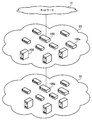
- FIG. 1 illustrates an information processing system according to the first embodiment.
- the information processing system according to the first embodiment includes a relay device 1, an information processing device 2, and nodes 3, 4, 5, and 6.
- the relay device 1, the information processing device 2, and the nodes 4, 5, and 6 are connected via a network.
- Node 3 communicates with nodes 4, 5, and 6 via relay device 1.
- the node 3 is a client device used by the user.
- the nodes 3, 4, 5, and 6 may be physical computers (sometimes referred to as physical machines) or virtual computers (sometimes referred to as virtual machines) that operate on the physical machines.
- the relay device 1 relays the data transmitted by the transmission source node.
- the relay device 1 includes a storage unit 1a, a setting unit 1b, and a control unit 1c.
- the storage unit 1a stores data used for the processing of the control unit 1c.
- the setting unit 1b receives first identification information indicating a user and second identification information indicating a transmission source node.
- the first identification information may be a user ID.
- the second identification information may be address information used for data transfer in the network.
- As the address information for example, an IP (Internet Protocol) address used for communication control in the third layer of the OSI (Open Systems Interconnection) reference model is conceivable.
- the setting unit 1b acquires, from the information processing apparatus 2, third identification information indicating a destination node that is allowed to access corresponding to the first identification information, based on the first identification information.
- the third identification information may be an address indicating a destination node.
- the third identification information may be an IP address.
- the setting unit 1b transmits the first identification information and the second identification information to the information processing device 2, and acquires the third identification information from the information processing device 2 as a response.
- the setting unit 1b sets the second identification information and the third identification information in the storage unit 1a as a combination that allows data relay.
- the control unit 1c determines whether to relay the data based on the information set in the storage unit 1a. To do. When the combination of identification information of each node included in the data is set in the storage unit 1a as a combination that allows relaying, the control unit 1c determines to relay the data. Then, the control unit 1c relays the data. On the other hand, if the storage unit 1a is not set as an allowable combination, the control unit 1c determines that the data is not relayed. Then, the control means 1c discards the data.
- the information processing apparatus 2 includes a storage unit 2a and a providing unit 2b.
- the storage unit 2a stores identification information indicating a destination node to which access is permitted in association with identification information of a plurality of users. Identification information indicating a plurality of destination nodes permitted to access may be associated with identification information of one user. There may be a plurality of identification information for each destination node.
- the providing unit 2b When the providing unit 2b receives the first identification information and the second identification information from the relay device 1, the providing unit 2b refers to the storage unit 2a and provides third identification information indicating a destination node corresponding to the first identification information. Search for. The providing unit 2b provides the relay apparatus 1 with the third identification information as the identification information of the destination node that is allowed to relay data in correspondence with the second identification information.
- the identification information of the relay device 1 is “DIDA”
- the identification information of the node 3 is “SID1”
- the identification information of the node 4 is “DID1”
- the identification information of the node 5 is “DID2”
- the identification information of the node 6 is “DID3”.
- the identification information of the user who uses the node 3 is “UID1”. Further, it is assumed that there is no information set in the storage unit 1a before step S1 shown below.
- the relay device 1 receives the data 3a from the node 3 (step S1).
- the data 3a includes a transmission source “SID1”, a destination “DIDA”, and user data “UID1”.
- the relay device 1 transmits “UID1” (and “SID1”) extracted from the data 3a to the information processing device 2 (step S2).
- the information processing apparatus 2 searches the storage means 2a using “UID1” as a key, and extracts a destination “DID1” that is allowed to be accessed in response to the user of “UID1”. Access to a plurality of destinations may be permitted per user. For example, the storage unit 2a also has a record registration indicating that access to the destination “DID2, DID3” is permitted for the user of “UID2”. The information processing apparatus 2 provides “DID1” to the relay apparatus 1 as a destination that is allowed to relay data corresponding to the transmission source “SID1”. The relay device 1 sets “SID1” and “DID1” in the storage unit 1a as a combination that allows data relay (step S3).
- the relay device 1 receives the data 3b from the node 3.
- the data 3b includes a transmission source “SID1”, a destination “DID1”, and user data “Data”.
- a combination of “SID1” and “DID1” is set in the storage unit 1a. Therefore, the relay device 1 relays the data 3b (step S4).
- the relay device 1 receives the data 3c from the node 3.
- the data 3c includes a transmission source “SID1”, a destination “DID2”, and user data “Data”.
- a combination of “SID1” and “DID2” is not set in the storage unit 1a. Therefore, the relay device 1 does not relay the data 3c (step S5).
- the relay device 1 acquires and holds the access control setting contents for each node for each user from the information processing apparatus 2, and determines whether to relay data based on the setting contents. For this reason, when it is desired to change the contents of access control for each user, the setting contents stored in the storage unit 2a may be changed. This is because the change content can be acquired by the relay device 1 and the change content can be reflected. Therefore, the administrator of the information processing system can save the trouble of setting the relay device 1 individually. In addition to the relay device 1, a plurality of relay devices may be operated. In this case, the trouble of searching for the relay device 1 to be set can be saved. Thus, access control for each user can be easily performed. In addition, the administrator's work can be saved, and access control can be set efficiently.
- a large number of relay devices and nodes can be operated.
- the processing power may be expanded by scaling out, and the number of nodes may increase.
- the connection relationship between the virtual machine and the virtual switch can be updated frequently. This is because a virtual machine is added to or deleted from a physical machine or moved to another physical machine depending on the operating status (user usage or load, etc.).
- the burden of changing the setting of each relay device (or virtual switch) at the time of connection change is particularly large. Therefore, it is particularly useful when the relay device 1 and the information processing device 2 are applied to a large-scale network.
- each relay device 1 acquires the setting contents of access control for each user from the information processing device 2. Therefore, even if a plurality of relay apparatuses 1 are provided for each network for which access control is desired, it is possible to easily set access control for each relay apparatus 1 for each user.
- the relay device 1 and the information processing device 2 may include a processor such as a CPU (Central Processing Unit) and a memory such as a RAM (Random Access Memory). In that case, the information processing of the relay device 1 and the information processing device 2 can be realized by the processor executing a program stored in the memory.
- a processor such as a CPU (Central Processing Unit) and a memory such as a RAM (Random Access Memory).
- the information processing of the relay device 1 and the information processing device 2 can be realized by the processor executing a program stored in the memory.
- FIG. 2 illustrates an information processing system according to the second embodiment.
- the information processing system according to the second embodiment includes relay devices 100, 100a, 100b, a management server 200, and business servers 300, 300a, 400, 400a.
- the relay device 100 is connected to the firewall 11.
- the firewall 11 is connected to the network 10.
- the network 10 may be a local area network (LAN) or a wide area network such as the Internet or a wide area network (WAN).
- LAN local area network
- WAN wide area network
- the firewall 11 monitors communication (for example, an IP packet) between the network 10 side (external side) and the relay device 100 side (internal side), and permits only communication that matches a predetermined rule. Reject communications that do not match
- the relay apparatuses 100, 100a, 100b, the management server 200, and the business servers 300, 300a are connected to the network 20.
- the relay device 100b and the business servers 400 and 400a are connected to the network 30.
- the networks 20 and 30 are LANs.
- the networks 20 and 30 may be networks of the same site, or networks of different sites (for example, a head office and a branch office).
- the relay devices 100, 100a, and 100b are switches that relay communication data.
- the relay apparatuses 100, 100a, and 100b may be L3 (Layer 3) switches or routers that perform routing between different network segments.
- the relay apparatuses 100, 100a, and 100b communicate with the management server 200, acquire access control information for each user, and perform access control based on the information.
- the relay devices 100, 100a, and 100b may be realized by a computer.
- the management server 200 is a server computer that centrally manages access control information for each user.
- the management server 200 provides access control information to the relay apparatuses 100, 100a, and 100b.
- the management server 200 may be connected to a network other than the network 20 (for example, the network 30).
- the business servers 300, 300a, 400, and 400a are server computers that execute business applications.
- the business servers 300, 300a, 400, and 400a provide services by business applications to the clients 500, 500a, 600, and 600a.
- the business servers 300, 300a, 400, and 400a have a Web server function. From the clients 500, 500a, 600, and 600a, services provided by the business servers 300, 300a, 400, and 400a can be used using software called a Web browser.
- the firewall 11 permits communication of an application port corresponding to HTTP (HyperText Transfer Protocol) or HTTPS (HTTP over Secure Socket Layer). Then, HTTP requests and responses can be transmitted and received between the clients 500, 500a and the business servers 300, 300a, 400, 400a. The same applies to FTP (File Transfer Protocol).
- HTTP HyperText Transfer Protocol
- HTTPS HTTP over Secure Socket Layer
- the user can access the information processing system according to the second embodiment by operating the clients 500, 500a, 600, and 600a.
- Clients 500, 500a, 600, and 600a are client computers.
- the clients 500, 500a, 600, and 600a may be electronic devices such as mobile phones and smart devices (for example, smartphones and tablet terminals).
- the clients 500 and 500a connect to the network 10 via the access point 12 and access the information processing system.
- the access point 12 is a relay device that relays wireless communication.
- the access point 12 may be a radio base station connected to the network 10 via a mobile communication network.
- the clients 600 and 600a are connected to the relay device 100a.
- Clients 600 and 600a may be connected to relay device 100a via another network.
- a service is used from the client 500.
- the user designates a URL (Uniform Resource Locator) of a business application to be used on a Web browser running on the client 500.
- the client 500 inquires a DNS (Domain Name System) server connected to the network 10 for an FQDN (Fully Quality Domain Name) in the URL, thereby resolving an IP address corresponding to the FQDN.
- DNS Domain Name System
- FQDN Full Quality Domain Name
- the Web browser transmits a request with the resolved IP address as the destination IP address.
- the service provided by the business server from the client 500 can be used.
- FQDN it is conceivable to provide a DNS server in a network segment accessible from the clients 600 and 600a.
- IP addresses used in the information processing system according to the second embodiment are as follows.
- the network address of the network 20 is “192.168.10.0”.
- the network address of the network 30 is “192.168.20.0”.
- the relay device 100 is “192.168.10.1”.
- the relay device 100a is “192.168.10.2”.
- the relay device 100b is “192.168.20.1”.
- the relay apparatus 100b may have an IP address on the network 20 side.
- the management server 200 is “192.168.10.10.”
- the business server 300 is “192.168.10.101”.
- the business server 300a is “192.168.10.102”.
- the business server 400 is “192.168.20.010”.
- the business server 400a is “192.168.20.102”.
- a predetermined IP address (for example, an IP address of the network 20) may be assigned to the clients 500 and 500a using, for example, a VPN (Virtual Private Network) technique. Then, a request specifying the IP address of each business server as the destination may be issued. In this case, for example, the client 500 or 500a is caused to execute VPN client software.
- a VPN server that communicates with a VPN client and assigns an IP address is provided between the firewall 11 and the relay apparatus 100. The VPN client encapsulates the IP packet including the request using a predetermined protocol and sends it to the VPN server. The VPN server transfers the request obtained by releasing the encapsulation to the relay device 100.
- a VPN may be implemented using a UTM (Unified Threat Management) device or the like.
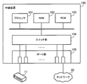
- FIG. 3 is a diagram illustrating a hardware example of the relay device according to the second embodiment.
- the relay device 100 includes a processor 101, a RAM 102, a ROM (Read Only Memory) 103, a switch unit 104, and a port unit 105.
- the relay apparatuses 100a and 100b can also be realized using the same units as the relay apparatus 100.
- the processor 101 executes a firmware program.
- the processor 101 may be a multiprocessor.
- the processor 101 is, for example, a CPU, MPU (Micro Processing Unit), DSP (Digital Signal Processor), ASIC (Application Specific Integrated Circuit), FPGA (Field Programmable Gate Array) or PLD (Programmable Logic Device).
- the processor 101 may be a combination of two or more elements of CPU, MPU, DSP, ASIC, FPGA, and PLD.
- the RAM 102 temporarily stores firmware programs and data.
- the ROM 103 stores firmware programs and data in advance.
- the ROM 103 may be a rewritable nonvolatile memory such as a flash memory.
- the switch unit 104 acquires a frame received at each port of the port unit 105 and outputs the frame to the processor 101.
- the switch unit 104 acquires a frame determined to be relayed from the processor 101.
- the switch unit 104 determines a port that outputs the frame based on a destination MAC (Media Access Control) address included in the frame.
- the switch unit 104 may hold a transfer table for determining a transfer destination port. When routing is performed in the network layer, the MAC address and the transfer destination port may be resolved from the destination IP address included in the IP packet in the frame using ARP (Address Resolution Protocol) or the like.
- the switch unit 104 outputs the frame to the determined port.
- the port unit 105 has a plurality of ports that communicate with other devices such as the management server 200 via the firewall 11 and the network 20.
- a part of the port unit 105 is directly or indirectly connected to the firewall 11 by a predetermined cable.
- the other part of the port unit 105 is directly or indirectly connected to the network 20 by a predetermined cable.
- FIG. 4 is a diagram illustrating a hardware example of the management server according to the second embodiment.
- the management server 200 includes a processor 201, a RAM 202, an HDD (Hard Disk Drive) 203, a communication unit 204, an image signal processing unit 205, an input signal processing unit 206, a disk drive 207, and a device connection unit 208. Each unit is connected to the bus of the management server 200.
- the business servers 300, 300 a, 400, 400 a and the clients 500, 500 a, 600, 600 a can also be realized using the same units as the management server 200.
- the processor 201 controls information processing of the management server 200.
- the processor 201 may be a multiprocessor.
- the processor 201 is, for example, a CPU, MPU, DSP, ASIC, FPGA, or PLD.
- the processor 201 may be a combination of two or more elements of CPU, MPU, DSP, ASIC, FPGA, and PLD.
- the RAM 202 is a main storage device of the management server 200.
- the RAM 202 temporarily stores at least part of an OS (Operating System) program and application programs to be executed by the processor 201.
- the RAM 202 stores various data used for processing by the processor 201.
- the HDD 203 is an auxiliary storage device of the management server 200.
- the HDD 203 magnetically writes data to and reads data from a built-in magnetic disk.
- the HDD 203 stores an OS program, application programs, and various data.
- the management server 200 may include other types of auxiliary storage devices such as flash memory and SSD (Solid State Drive), or may include a plurality of auxiliary storage devices.
- the communication unit 204 is an interface that can communicate with other computers and the relay devices 100, 100 a, 100 b through the network 20.
- the communication unit 204 may be a wired interface or a wireless interface.
- the image signal processing unit 205 outputs an image to the display 21 connected to the management server 200 in accordance with an instruction from the processor 201.
- a CRT (CathodeathRay Tube) display As the display 21, a CRT (CathodeathRay Tube) display, a liquid crystal display, or the like can be used.
- the input signal processing unit 206 acquires an input signal from the input device 22 connected to the management server 200 and outputs it to the processor 201.
- the input device 22 for example, a pointing device such as a mouse or a touch panel, a keyboard, or the like can be used.
- the disk drive 207 is a drive device that reads a program and data recorded on the optical disk 23 using a laser beam or the like.
- the optical disc 23 for example, a DVD (Digital Versatile Disc), DVD-RAM, CD-ROM (Compact Disc Read Only Memory), CD-R (Recordable) / RW (ReWritable) or the like can be used.
- the disk drive 207 stores the program and data read from the optical disk 23 in the RAM 202 or the HDD 203 in accordance with an instruction from the processor 201.
- the device connection unit 208 is a communication interface for connecting peripheral devices to the management server 200.
- the memory device 24 and the reader / writer device 25 can be connected to the device connection unit 208.
- the memory device 24 is a recording medium equipped with a communication function with the device connection unit 208.
- the reader / writer device 25 is a device that writes data to the memory card 26 or reads data from the memory card 26.
- the memory card 26 is a card type recording medium.
- the device connection unit 208 stores a program or data read from the memory device 24 or the memory card 26 in the RAM 202 or the HDD 203 in accordance with an instruction from the processor 201.
- FIG. 5 is a diagram illustrating an example of software according to the second embodiment.
- 5 may be a module of a program executed by the relay devices 100, 100a, 100b and the processor of the management server 200.
- 5 may be an electronic circuit such as an ASIC or FPGA included in the relay apparatuses 100, 100a, and 100b and the management server 200.
- the firewall 11 and the access point 12 are not shown.
- the relay device 100 includes a storage unit 110 and an access control unit 120.
- the storage unit 110 stores information used for processing of the access control unit 120.
- the information includes a session management table.
- the session management table is information for access control in which a combination of IP addresses permitted to be relayed is registered. Below, the information which shows the said combination may be called session information.
- the storage unit 110 can be mounted using the RAM 120.
- the access control unit 120 receives information for login authentication from the clients 500 and 500a.
- the login authentication may be referred to as network login authentication.
- the network login authentication is login authentication for connecting to the networks 20 and 30.
- login authentication may occur individually for services provided by each business server.
- the term “login authentication” refers to network login authentication.
- the access control unit 120 receives login authentication information from the clients 500 and 500a.
- the access control unit 120 transmits the login authentication information to the management server 200 and requests authentication.
- the information for login authentication includes a user ID and a password.
- the login authentication information may include client address information (IP address or MAC address).
- the access control unit 120 may provide the clients 500 and 500a with a GUI (Graphical User Interface) for inputting login authentication information.
- GUI Graphic User Interface
- the GUI can be provided to the clients 500 and 500a as a Web page (login page).
- a web server that provides a login page may be provided separately. Then, when an access specifying the business server as a destination is received from the clients 500 and 500a before login authentication, the access destination may be redirected to the URL of the login page.
- the access control unit 120 may receive the user ID and password input on the login page.
- the access control unit 120 receives session information corresponding to the authentication result from the management server 200 and registers it in the session management table stored in the storage unit 110. Then, when the access control unit 120 relays a request addressed to the business servers 300, 300 a, 400, and 400 a after login authentication, the access control unit 120 determines whether to relay the request based on the session management table stored in the storage unit 110. Determine whether. When relaying the request, the access control unit 120 outputs the request to the switch unit 104. The switch unit 104 refers to the destination of the request and sends the request from a predetermined port. When the request is not relayed, the access control unit 120 discards the request.
- the storage unit 110 is an example of the storage unit 1a according to the first embodiment.
- the access control unit 120 is an example of the setting unit 1b and the control unit 1c according to the first embodiment.
- the relay device 100a includes a storage unit 110a and an access control unit 120a.
- the relay device 100b includes a storage unit 110b and an access control unit 120b.
- the storage units 110a and 110b store a session management table.
- the access control unit 120a performs access control on the business servers 300, 300a, 400, and 400a based on the session management table stored in the storage unit 110a.
- the access control unit 120b performs access control on the business servers 300, 300a, 400, and 400a based on the session management table stored in the storage unit 110b.
- the management server 200 includes a storage unit 210 and a management unit 220.
- the storage unit 210 stores information used for processing of the management unit 220.
- the information includes a user management table, an access management table, and a connection management table.
- the user management table is information in which basic user information is registered.
- the basic user information includes, for example, information indicating whether or not simultaneous connection using a user ID, a password, and a plurality of clients (hereinafter sometimes referred to as multiple connection) is possible.
- the access management table is information in which the IP address of a business server that allows access for each user is registered.
- the connection management table is information for managing the current connection state in the relay apparatuses 100, 100a, and 100b.
- the storage unit 210 can be mounted using the RAM 202 or the HDD 203.
- the management unit 220 When the management unit 220 receives an authentication request from the relay devices 100, 100 a, 100 b, the management unit 220 executes an authentication process based on the information stored in the storage unit 210. The management unit 220 generates session information according to the authentication result and provides it to the requesting relay device.
- the storage unit 210 is an example of the storage unit 2a according to the first embodiment.
- the management unit 220 is an example of the providing unit 2b according to the first embodiment.
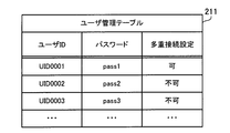
- FIG. 6 illustrates an example of a user management table according to the second embodiment.
- the user management table 211 is stored in the storage unit 210.
- the user management table 211 includes items of user ID, password, and multiple connection setting.
- the user ID is registered in the user ID item.
- a password is registered in the password item.
- permission information indicating whether multiple connection is permitted is registered. For example, the information “permitted” is registered in the item of “multiple connection setting” and the information “impossible” is registered in the item of “multiple connection setting”.
- the user with the user ID “UID0001” is hereinafter referred to as user A.
- the user with the user ID “UID0002” is called user B.
- the user with the user ID “UID0003” is called user C.
- the setting contents of the user management table 211 can be appropriately changed, for example, by an administrator of the information processing system, for example, when it is desired to change permission information for multiple connections for each user.
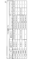
- FIG. 7 illustrates an example of an access management table according to the second embodiment.
- the access management table 212 is stored in the storage unit 210.
- the access management table 212 includes items of ROLE, user ID, terminal IP address, terminal MAC address, and ACL (Access Control List).
- ROLE item a ROLE number for identifying a record (data unit for one line) is registered.
- ROLE1 indicates a record in which the ROLE number “1” is set in the ROLE item of the access management table 212.
- the term ROLE may be used as a term indicating one record in the access management table 212.
- the user ID is registered in the user ID item.
- the IP address of the client is registered in the terminal IP address item.
- the MAC address of the client is registered in the terminal MAC address item.
- ACL item a list of IP addresses of business servers permitted to access is registered.
- a plurality of IP addresses can be registered per ROLL. The numbers “1”, “2”, “3”, and “4” obtained by subdividing the ACL items are given for convenience. Further, when there are a large number of access destination servers, five or more IP addresses may be registered.
- the access management table 212 includes items for which no information is registered in each record. In that case, a hyphen symbol “-” is shown. When “-” is registered in the terminal IP address item, it indicates an arbitrary terminal IP address. When “ ⁇ ” is registered in the item of the terminal MAC address, an arbitrary MAC address is indicated.
- ROLE is “1”
- user ID is “UID0001”
- terminal IP address is “192.168.10.11”
- terminal MAC address is “08-b4-25-9e-0c”.
- -46 ACL“ 192.168.10.101 ”,“ 192.168.10.102 ”,“ 192.168.20.010 ”,“ 192.168.20.102 ”are registered. ing.
- the ACL Indicates that access to the IP address is permitted. In this case, access to the business servers 300, 300a, 400, 400a is permitted.
- the ACL is “192.168.10.101” and “192.168.20” for the same user ID “UID0001” and IP address “192.168.10.11”. .101 ".
- ROLE for each user is registered in the access management table 212.
- a plurality of ROLEs may be registered for one user.
- a range of IP addresses that allow access may be registered in the ACL using a network address or the like.
- a single business server may use a plurality of IP addresses (for example, for each service to be provided). In that case, it is only necessary to register in the ACL only the IP address that is desired to be allowed to access among the plurality of IP addresses of the one business server.
- the setting contents of the access management table 212 can be changed when a user is added / deleted, a business server is added / deleted, a network connection of the business server is changed, or the like.
- the administrator of the information processing system can change the setting contents of the access management table 212 when these changes occur.
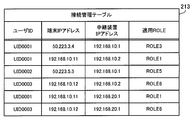
- FIG. 8 is a diagram illustrating an example of a connection management table according to the second embodiment.
- the connection management table 213 is stored in the storage unit 210.
- the connection management table 213 is updated by the management unit 220.
- the connection management table 213 includes items of user ID, terminal IP address, relay device IP address, and applicable ROLE.
- the user ID is registered in the user ID item.
- the IP address of the client is registered in the terminal IP address item.
- the relay device IP address item the IP address of the relay device that has made the authentication request is registered.
- the applied ROLE item information indicating the ROLE to be applied as a result of the authentication is registered.
- the applied ROLE is a ROLE provided to the relay apparatus by the management server 200. After receiving the provision of ROLE, the relay apparatus can perform access control based on the ROLE.
- the connection management table 213 can also be referred to as a ROLE history provided to the relay device.
- the user ID is “UID0001”
- the terminal IP address is “50.223.3.4”
- the relay device IP address is “192.168.10.1”
- the applicable ROLE is “ROLE3”. "Is registered.
- IP address “50.223.3.4” is the IP address of the client 500, for example.
- the user ID is “UID0001”
- the terminal IP address is “192.168.10.11”
- the relay device IP address is “192.168.10.2”
- the applicable ROLE is “ Information “ROLE1” is registered.
- IP address “192.168.10.11” is, for example, the IP address of the client 600.
- connection management table 213 Similar records are registered for the user B with the user ID “UID0002” and the user C with the user ID “UID0003”. The meaning of each information registered in the record is as described above.
- the user B uses the client 500a.
- the IP address “50.23.5.5” is the IP address of the client 500a.
- the user C uses the client 600a.
- the IP address “192.168.10.12” is the IP address of the client 600a.
- Two records may be registered in the connection management table 213 for one client.
- the second record for the clients 600 and 600a is registered as follows.
- the user ID is “UID0001”
- the terminal IP address is “192.168.10.11”
- the relay device IP address is “192.168.20.1”
- the applicable ROLE is “ROLE1”. "Is registered.
- the user ID is “UID0003”
- the terminal IP address is “192.168.10.12”
- the relay device IP address is “192.168.20.1”
- the applicable ROLE is “ Information "ROLE6" is registered.
- the relay device may be registered using a device other than the relay device IP address. For example, a predetermined identification name is assigned in advance to each of the relay devices 100, 100a, and 100b.
- the connection management table 213 may include an item for setting the identification name instead of the relay device IP address item.
- FIG. 9 is a diagram illustrating an example of a session management table according to the second embodiment.
- FIG. 9A illustrates the session management table 111.
- the session management table 111 is stored in the storage unit 110.
- the session management table 111 is updated by the access control unit 120.
- the session management table 111 includes items of ROLE, terminal IP address, and ACL.
- the ROLE item the ROLE number of the ROLE that is the basis of the session information is registered.
- the IP address of the client is registered in the terminal IP address item.
- the ACL item an IP address of a business server that allows relaying is registered.
- the numbers “1”, “2”, “3”, and “4”, which are subdivided ACL items, are assigned for convenience as in the access management table 212.
- the session management table 111 there is a part where information is not registered in each record. The hyphen symbol “-” is written in that place.
- the session management table 111 information that ROLE is “3”, the terminal IP address is “50.223.3.4”, and the ACL is “192.168.10.101” is registered. This indicates that relaying of communication data whose source / destination IP address pairs are “50.223.3.4” and “192.168.10.101” is permitted. That is, in the case of the source IP address “50.223.3.4” and the destination IP address “192.168.10.101” (upstream), the source IP address “192.168.10.101”, the destination Relaying is allowed even in the case of the IP address “50.223.3.4” (downlink).
- ROLE is “5”
- the terminal IP address is “50.223.55.5”
- ACL is “192.168.10.101”, “192.168.10.102”.
- FIG. 9B illustrates the session management table 111a.
- the session management table 111a is stored in the storage unit 110a.
- the session management table 111a is updated by the access control unit 120a. Since the setting contents of the items included in the session management table 111a are the same as those of the session management table 111, description thereof is omitted.
- FIG. 9C illustrates the session management table 111b.
- the session management table 111b is stored in the storage unit 110b.
- the session management table 111b is updated by the access control unit 120b. Since the setting contents of the items included in the session management table 111b are the same as those of the session management table 111, description thereof is omitted.
- the session management tables 111, 111a, and 111b correspond to a session information group held by the relay devices 100, 100a, and 100b in the connection state indicated by the connection management table 213.
- One record is one session information.
- the session management tables 111, 111a, and 111b may include items of user ID and password.
- the management server 200 may provide session information including a user ID and a password to the relay devices 100, 100a, and 100b. In this way, for example, when the relay device 100 receives an access from the terminal IP address registered in the session management table 111, the relay device 100 can record the user ID for the terminal IP address in the access log.
- the session management tables 111, 111a, and 111b may include an item of MAC address.
- the management server 200 may provide session information including the terminal MAC address to the relay devices 100, 100a, and 100b. This is because, for example, it may be possible to use a MAC address for identifying the client 500 or the like in the relay apparatus 100.
- FIG. 10 is a diagram illustrating an example of communication data according to the second embodiment.
- FIG. 10 illustrates communication data transmitted and received by the information processing system according to the second embodiment.
- the frame 40 is an example of an Ethernet frame (Ethernet and Ethernet are registered trademarks).
- the frame 40 includes fields of a preamble, a destination MAC address, a transmission source MAC address, a type, a payload, and FCS (Frame Check Sequence).
- Preamble is a field that contains a signal for synchronization.
- the destination MAC address is a field for setting a destination MAC address used for path selection in the second layer (data link layer) of the OSI reference model.
- the source MAC address is a field for setting the source MAC address.
- the type is a field for setting information indicating an upper layer protocol (for example, IP).
- the payload is a field for setting the main body of data handled by the upper layer protocol.
- FCS is a field for setting information for detecting a frame error.
- the IP packet 50 is included in the payload of the frame 40.
- the IP packet 50 is sometimes called a datagram.
- the IP packet 50 includes a source IP address, a destination IP address, and data fields.
- the transmission source IP address is a field for setting a transmission source IP address used for route selection in the third layer (network layer) of the OSI reference model.
- the destination IP address is a field for setting the source IP address.
- Data is a field for setting the communication data body.
- Data 60 is included in the data field of the IP packet 50.
- the data 60 may include a user ID and a password.
- the data 60 may include an IP address or a MAC address of the client.
- the user ID, password, and address information included in the data 60 may be information on the seventh layer (application layer) of the OSI reference model.
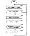
- FIG. 11 is a flowchart illustrating an example of authentication processing according to the second embodiment. In the following, the process illustrated in FIG. 11 will be described in order of step number.
- the access control unit 120 receives information for login authentication from the client 500.
- the user A uses a web browser on the client 500 to access a web page (login page) for entering a user ID and password.
- the user A inputs his / her user ID “UID0001” and password “pass1” on the login page.
- the client 500 transmits a frame including the input information (login authentication information) to the relay apparatus 100.
- the access control unit 120 receives the frame.
- the IP packet in the frame includes a source IP address and a source MAC address. In this case, the transmission source IP address is “50.223.3.4”.
- the source MAC address is a predetermined MAC address.
- the access control unit 120 also extracts the address information and adds it to the login authentication information.
- Step S12 The access control unit 120 transmits an authentication request including information for login authentication to the management server 200.
- the login authentication information is stored in the data portion of the IP packet and transmitted to the management server 200.
- the management unit 220 receives an authentication request from the relay device 100.
- Step S13 The management unit 220 refers to the user management table 211 stored in the storage unit 210, and collates the user ID and the password. If the verification is successful, the process proceeds to step S14. If the collation is not successful (collation failure), the process proceeds to step S19. Specifically, if the set of the user ID and password included in the authentication request is registered in the user management table 211, the verification is successful. If the combination of the user ID and password included in the authentication request is not registered in the user management table 211, the verification is unsuccessful.
- the management unit 220 refers to the access management table 212 stored in the storage unit 210 and searches the ACL.
- the search key is the user ID, source IP address, and source MAC address included in the authentication request.
- the management unit 220 extracts a corresponding record as a search result if there is at least a record with a matching user ID. There may be multiple search results. In that case, one with the largest matching key is extracted as a search result.
- the user ID “UID0001” and the IP address “50.223.3.4” (and the source MAC address) of the client 500 are acquired.
- the record “ROLE3” is obtained as a search result.
- Step S15 The management unit 220 determines whether or not the ACL has been searched in Step S14. If the search is successful, the process proceeds to step S16. If not, the process proceeds to step S19.
- Step S16 The management unit 220 determines whether there is a multiple connection restriction for the user being processed. If there is a restriction on multiple connections, the process proceeds to step S19. If there is no multiple connection restriction, the process proceeds to step S17.
- Step S17 The management unit 220 updates the connection management table 213. Specifically, the management unit 220 registers, in the connection management table 213, the user ID received in the authentication request, the transmission source IP address (terminal IP address), and the ROLE number (application ROLE) of the record searched in step S14. Further, in the authentication request (IP packet included in the frame), the IP address of the relay device 100 is set as the source IP address. Therefore, the IP address of the relay device 100 (relay device IP address) is also registered in the connection management table 213.
- Step S18 The management unit 220 generates session information based on the access management table 212. Specifically, the combination of the ROLE number of the ROLE searched in step S14, the terminal IP address, and the ACL is used as the session information.
- the management unit 220 sets the source IP address received in the authentication request as the terminal IP address, and uses it as session information.
- the management unit 220 may provide the session information including the user ID (hereinafter the same). The management unit 220 responds to the relay apparatus 100 with the session information and authentication success. Then, the process proceeds to step S20.
- Step S19 The management unit 220 responds to the relay device 100 with an authentication failure.
- Step S20 The access control unit 120 receives a response to the authentication request from the management server 200, and determines whether the authentication is successful based on the response. If the authentication is successful, the process proceeds to step S21. If it is an authentication failure, the process proceeds to step S23.
- Step S21 The access control unit 120 registers the session information received together with the successful authentication in the session management table 111 stored in the storage unit 110.
- the record “ROLE3” is registered in the session management table 111.
- Step S22 The access control unit 120 responds to the client 500 with a successful authentication. Then, the process ends.
- Step S ⁇ b> 23 The access control unit 120 sends an authentication failure response to the client 500. Then, the process ends.
- step S18 even if there is no terminal IP address record that matches the accepted source IP address, a predetermined ROLE (ROLE for which no terminal IP address is set) is extracted for the corresponding user to generate session information. To do. For this reason, for example, even when the IP address of the client 500 is dynamically assigned, the predetermined ROLE can be applied.
- DHCP Dynamic Host Configuration Protocol
- step S18 the management unit 220 sets the IP address of the client 600 acquired from the relay device 100 when generating session information using the terminal IP address that has not been set in the ROLE of the access management table 212.
- the access control unit 120 may perform the setting process. Specifically, the management unit 220 generates session information with no terminal IP address set for “ROLE3”, and sends the session information to the relay device 100.
- step S21 the transmission source IP address extracted in step S11 is set in the session information by the responsibility of the access control unit 120, and is registered in the session management table 111.
- the password is managed by the user management table 211
- the password may be managed by the access management table 212. If it does so, even if it is the same user, a different password for every ROLE can be utilized for authentication. That is, the management unit 220 uses a password as a key when searching for an ACL in step S14. In this case, step S13 may be skipped.
- FIG. 12 is a flowchart illustrating an example of relay processing according to the second embodiment. In the following, the process illustrated in FIG. 12 will be described in order of step number.
- Step S31 The access control unit 120 receives communication data to be relayed.
- this communication data is a request transmitted from the client 500 to the business server 300.
- the destination IP address of the request is “192.168.10.101”.
- the source IP address of the request is “50.223.3.4”.
- the access control unit 120 extracts a transmission source IP address from the IP packet of communication data.
- Step S32 The access control unit 120 refers to the session management table 111 stored in the storage unit 110 and determines whether there is session information corresponding to the transmission source IP address. If there is session information corresponding to the source IP address, the process proceeds to step S38. If there is no session information corresponding to the source IP address, the process proceeds to step S33.
- Step S33 The access control unit 120 transmits a confirmation request for inquiring whether or not the transmission source IP address is registered in the connection management table 213 to the management server 200.
- This confirmation request may be called an authentication confirmation request.
- the reason for this is as follows. If the authentication process described with reference to FIG. 11 is successful (if authenticated), the management server 200 should have registered the transmission source IP address in the connection management table 213. For this reason, the confirmation as to whether or not the transmission source IP address has been registered in the connection management table 213 results in confirming the success or failure of the authentication process (whether or not it has been authenticated). The processing procedure of the management server 200 for the confirmation request will be described later.
- Step S34 The access control unit 120 receives a response to the authentication confirmation request from the management server 200.
- the response includes a confirmation result as to whether or not authentication has been completed. If the confirmation result is authenticated, the session information corresponding to the applied ROLE is included in the response.
- the session information includes a combination of the source IP address and ACL extracted in step S31.
- Step S35 The access control unit 120 determines whether or not it has been authenticated based on the response. If already authenticated, the process proceeds to step S36. If not authenticated, the process proceeds to step S37.
- Step S ⁇ b> 36 The access control unit 120 registers the received session information in the session management table 111. Then, the process proceeds to step S38.
- Step S37 The access control unit 120 redirects to the login page. For example, an HTTP request (request in step S31) received from the client 500 is replaced with a request specifying the URL of the login page and transferred. Provision of the login page may be performed by the relay apparatus 100 or another Web server. Then, a login page is displayed on the Web browser of the client 500, and the user is prompted to input a user ID and password (authentication information). Then, the process ends.
- the procedure after accepting the user ID and password is the procedure of the authentication process in FIG.
- the communication data received in step S31 is not relayed.
- the communication data may be stored in a RAM or the like, and relaying may be suspended. After successful authentication, it may be determined again whether relaying is to be performed.
- Step S38 The access control unit 120 refers to the session management table 111 and determines whether or not relaying between the source / destination IP addresses extracted in step S31 is permitted. If relaying is permitted, the process proceeds to step S39. If relaying is not permitted, the process proceeds to step S40.
- Step S39 The access control unit 120 outputs the communication data received in step S31 to the switch unit 104.
- the switch unit 104 transfers communication data to the destination IP address (communication data is relayed). Then, the process ends.
- Step S40 The access control unit 120 discards the communication data received in step S31. That is, the communication data is not relayed. Then, the process ends. In this way, the relay device 100 relays communication data.
- the relay device 100 collates the combination of the source IP address and the destination IP address included in the communication data with the session management table 111, and determines whether to relay the communication data. When communication data is not relayed, the client 500 may be notified that access to the destination IP address is not permitted.
- the reason for requesting authentication confirmation to the management server 200 as in steps S33 and S34 is that one client may access different business servers via a plurality of relay devices.
- the clients 600 and 600a may access the business servers 400 and 400a via both the relay devices 100a and 100b.
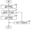
- FIG. 13 is a flowchart illustrating an authentication confirmation example (part 1) according to the second embodiment. In the following, the process illustrated in FIG. 13 will be described in order of step number.
- Step S41 The management unit 220 receives the confirmation request in step S33 from the relay device 100.
- the confirmation request includes the IP address of the client to be confirmed.
- Step S42 The management unit 220 refers to the connection management table 213 stored in the storage unit 210, and determines whether or not the IP address has been registered. If already registered, the process proceeds to step S43. If not registered, the process proceeds to step S45. If there is a record in which the IP address is set in the terminal IP address field of the connection management table 213, it is registered. On the other hand, if there is no record in which the IP address is set in the terminal IP address item of the connection management table 213, the record is not registered.
- Step S43 The management unit 220 updates the connection management table 213. Specifically, the management unit 220 adds a record including the client IP address (terminal IP address) received in the confirmation request to the connection management table 213.
- the record to be added includes the user ID of the record that is the basis for determining that it has been registered in step S42 and the setting value of the applied ROLE. Further, the added record includes the IP address (relay device IP address) of the relay device 100 that is the transmission source IP address of the confirmation request.
- the confirmation request (the IP packet included in the frame) includes the IP address of the relay device 100 as the source IP address. This IP address is set in the item of the relay device IP address of the record.
- Step S44 The management unit 220 generates session information based on the access management table 212. Specifically, the combination of the ROLE number of the application ROLE set in the new record in step S43, the terminal IP address, and the ACL corresponding to the ROLE number is used as session information. Then, in response to the confirmation request, the management unit 220 responds to the relay apparatus 100 that it has been authenticated. The response includes the generated session information. Then, the process ends.
- Step S ⁇ b> 45 The management unit 220 responds to the relay apparatus 100 that the authentication request is not authenticated. Then, the process ends. In this way, the management server 200 executes authentication confirmation processing in response to the confirmation request from the relay apparatus 100.
- the relay apparatuses 100, 100a, 100b and the management server 200 that executes the procedures of FIGS. 11 to 13 will be described.
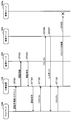
- FIG. 14 is a diagram illustrating a specific example (part 1) of communication according to the second embodiment. In the following, the process illustrated in FIG. 14 will be described in order of step number. It is assumed that there is no entry (registered record) in the session management table 111 and the connection management table 213 immediately before step ST101.
- Step ST101 The client 500 transmits the login authentication information input by the user A on the login page to the relay device 100.
- the authentication information includes a user ID “UID0001” and a password “pass1”.
- the relay device 100 receives authentication information.
- the authentication information is sent to the relay device 100 using the frame described with reference to FIG.
- Step ST102 The relay device 100 extracts the source IP address “50.223.3.4” and the source MAC address from the frame.
- Relay device 100 adds the source IP address and source MAC address to the authentication information received in step ST101. That is, a new frame is generated in which the extracted source IP address and source MAC address are set in the data portion of the IP packet.
- the relay device 100 transmits the frame to the management server 200. This frame corresponds to an authentication request.
- the authentication request includes the user ID, password, transmission source IP address and transmission source MAC address of the frame received in step ST101 as authentication information.
- the management server 200 receives the authentication request.
- Step ST103 The management server 200 collates the user ID and password included in the authentication request with the registered content of the user management table 211.
- the user management table 211 a set of a user ID “UID0001” and a password “pass1” is registered. For this reason, this verification succeeds.
- the access management table 212 includes the user ID “UID0001”, the terminal IP address “ ⁇ ”, and the MAC address “ ⁇ ”. “ROLE3” exists.
- the management server 200 identifies “ROLE3” as the application ROLE. Further, according to the user management table 211, there is no restriction on the multiple connection for the user A (since the multiple connection setting is “possible”).
- the management server 200 generates session information including the transmission source IP address “50.223.3.4” using “ROLE3”, and transmits it to the relay apparatus 100 together with a notification of successful authentication.
- the relay device 100 receives session information and a notification of successful authentication.
- the management server 200 also updates the connection management table 213. Specifically, a record of user ID “UID0001”, terminal IP address “50.223.3.4”, relay device IP address “192.168.10.1”, and applicable ROLE “ROLE3” is stored in the connection management table 213. Add to
- Step ST104 The relay device 100 registers the received session information in the session management table 111. In this case, a record of ROLE “3”, terminal IP address “50.223.3.4”, ACL “192.168.10.101” is registered in the session management table 111.
- the relay apparatus 100 transmits a notification of successful authentication to the client 500.
- the client 500 receives a notification of successful authentication.
- Step ST105 The client 500 transmits a request addressed to the business server 300.
- the destination IP address of the request is “192.168.10.101”.
- the source IP address is “50.223.3.4”.
- the relay device 100 receives the request.
- Step ST106 The relay device 100 collates the source / destination IP address pair included in the IP packet of the received request with the registered content of the session management table 111.
- the session management table 111 there is a record of “ROLE3” registered in step ST104. That is, relaying of the request is permitted. Therefore, the relay device 100 transfers the request to the business server 300.
- the business server 300 receives the request.
- Step ST107 The business server 300 executes processing according to the received request.
- the business server 300 transmits a response corresponding to the processing result to the client 500.
- the response is transmitted to the client 500 via the relay device 100.
- the relay apparatus 100 also determines that relaying is permitted for communication from the business server 300 to the client 500 based on the session management table 111. Therefore, the relay device 100 relays the response.
- the client 500 receives the response.
- Step ST108 The client 500 transmits a request addressed to the business server 300a.
- the request is transferred to the relay apparatus 100 via the firewall 11.
- the destination IP address included in the IP packet of the request is “192.168.10.102”.
- the transmission source IP address is “50.223.3.4”.
- the relay device 100 receives the request.
- Step ST109 The relay device 100 collates the source / destination IP address pair included in the IP packet of the received request with the registered content of the session management table 111.
- the session management table 111 includes a record including the transmission source IP address “50.223.3.4”.
- the corresponding ACL does not include the destination IP address “192.168.10.102”. That is, relaying of the request is not permitted. Therefore, the relay device 100 discards the request without relaying the request.
- the client 500 can access the business server 300 registered in the ACL of “ROLE3” through the network login authentication.
- access to other business servers in the ACL of “ROLE3” is not permitted. For this reason, access to other business servers is restricted by the relay device 100.
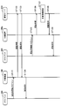
- FIG. 15 is a diagram illustrating a specific example (part 2) of communication according to the second embodiment. In the following, the process illustrated in FIG. 15 will be described in order of step number. It is assumed that there are no entries in the session management table 111 and the connection management table 213 immediately before step ST111.
- Step ST111 The client 500 transmits a request addressed to the business server 300.
- the request is transferred to the relay apparatus 100 via the firewall 11.
- the relay device 100 receives the request.
- the destination IP address included in the IP packet of the request received by the relay device 100 is “192.168.10.101”.
- the transmission source IP address is “50.223.3.4”.
- Step ST112 The relay device 100 collates the source / destination IP address pair included in the IP packet of the received request with the registered content of the session management table 111. There is no entry in the session management table 111 at this time. That is, there is no record including the source IP address “50.223.3.4”. Therefore, the relay device 100 transmits an authentication confirmation request to the management server 200.
- the confirmation request (data portion of the IP packet) includes the source IP address “50.223.3.4”.
- the management server 200 receives the confirmation request.
- Step ST113 The management server 200 collates the transmission source IP address included in the confirmation request with the registered content of the connection management table 213. There is no entry in the connection management table 213 at this time. That is, there is no record including the source IP address “50.223.3.4”. Therefore, the management server 200 responds to the relay apparatus 100 that it is not authenticated. The relay device 100 receives the response.
- Step ST114 The relay device 100 redirects the received request to the login page.
- the relay apparatus 100 can provide a login page, for example, the data of the login page is provided to the client 500.
- the client 500 receives the login page data. You may redirect to a login page provided by another Web server. Then, the Web browser of the client 500 presents a login page to the user A.
- Step ST115 The client 500 transmits the login authentication information input by the user A on the login page to the relay device 100.
- the authentication information includes a user ID “UID0001” and a password “pass1”.
- the relay device 100 receives authentication information (frame).
- Step ST116 The relay device 100 extracts the transmission source IP address “50.223.3.4” and the transmission source MAC address from the received frame.
- the relay device 100 generates a new frame (authentication request) in which the extracted transmission source IP address and transmission source MAC address are set in the data portion of the IP packet, and transmits the frame to the management server 200.
- the management server 200 receives the authentication request.
- the authentication request includes a user ID and a password.
- Step ST117 The management server 200 generates session information in the same manner as in step ST103 of FIG. In addition, a new record is added to the connection management table 213.
- the management server 200 transmits the generated session information and a notification of successful authentication to the relay device 100.
- the relay device 100 receives session information and a notification of successful authentication.
- Step ST118 The relay apparatus 100 registers the session information received from the management server 200 in the session management table 111, similarly to step ST104 in FIG.
- the relay apparatus 100 transmits a notification of successful authentication to the client 500.
- the client 500 receives a notification of successful authentication.
- the client 500 can access the business server 300 by the same procedure as that after step ST105 in FIG. Next, a case where the user A performs network login authentication using both the clients 500 and 600 will be exemplified.
- FIG. 16 is a diagram illustrating a specific example (part 3) of communication according to the second embodiment. In the following, the process illustrated in FIG. 16 will be described in order of step number. It is assumed that there are no entries in the session management tables 111 and 111a and the connection management table 213 immediately before step ST121.
- Step ST121 The client 500 transmits the login authentication information input by the user A on the login page to the relay device 100.
- the authentication information includes a user ID “UID0001” and a password “pass1”.
- the relay device 100 receives authentication information (frame).
- Step ST122 The relay device 100 extracts the transmission source IP address “50.223.3.4” and the transmission source MAC address from the received frame.
- the relay device 100 generates a new frame (authentication request) in which the extracted transmission source IP address and transmission source MAC address are set in the data portion of the IP packet, and transmits the frame to the management server 200.
- the management server 200 receives the authentication request.
- the authentication request includes a user ID and a password.
- Step ST123 The management server 200 generates session information in the same manner as in step ST103 of FIG. Also, a record is added to the connection management table 213. Specifically, the record includes a user ID “UID0001”, a terminal IP address “50.223.3.4”, a relay device IP address “192.168.10.1”, and an applicable ROLE “ROLE3”.
- the management server 200 transmits the generated session information and a notification of successful authentication to the relay device 100.
- the relay device 100 receives session information and a notification of successful authentication.
- Step ST124 The relay apparatus 100 registers the session information ("ROLE3" record) received from the management server 200 in the session management table 111, similarly to step ST104 of FIG.
- the relay apparatus 100 transmits a notification of successful authentication to the client 500.
- the client 500 receives a notification of successful authentication.
- Step ST125 The client 600 transmits the login authentication information input by the user A on the login page to the relay device 100a.
- the authentication information includes a user ID “UID0001” and a password “pass1”.
- the relay device 100a receives the authentication information (frame).
- Step ST126 The relay device 100a extracts the transmission source IP address “192.168.10.11” and the transmission source MAC address “08-b4-25-9e-0c-46” from the received frame.
- the relay device 100a generates a new frame (authentication request) in which the extracted transmission source IP address and transmission source MAC address are set in the data portion of the IP packet, and transmits the frame to the management server 200.
- the management server 200 receives the authentication request.
- the authentication request includes a user ID and a password.
- Step ST127 The management server 200 collates the user ID and password included in the authentication request with the registered contents of the user management table 211.
- the user management table 211 a set of a user ID “UID0001” and a password “pass1” is registered. For this reason, this verification succeeds.
- the access management table 212 includes a record including the user ID “UID0001”, the source IP address “192.168.10.11”, and the source MAC address “08-b4-25-9e-0c-46”. “ROLE1” exists.
- the management server 200 identifies “ROLE1” as the application ROLE. Furthermore, a record “ROLE3” has already been added to the connection management table 213 in step ST123.
- the user ID “UID0001” can be set to multiplex connection. Therefore, the management server 200 determines that a new connection with “ROLE1” is permitted (that is, there is no restriction on multiple connections).
- Step ST128) The management server 200 generates session information using “ROLE1” in the access management table 212, and transmits it to the relay device 100a together with a notification of successful authentication.
- the relay device 100a receives session information and a notification of successful authentication.
- the management server 200 also updates the connection management table 213. Specifically, records of user ID “UID0001”, terminal IP address “192.168.10.11”, relay device IP address “192.168.10.2”, and applicable ROLE “ROLE1” are stored in the connection management table 213. Add to
- Step ST129 The relay device 100a registers the session information received from the management server 200 in the session management table 111a (a record of “ROLE1”).
- the relay device 100a transmits a notification of successful authentication to the client 600.
- the client 600 receives a notification of successful authentication.
- the user management table 211 In this way, whether or not multiple connections are allowed can be controlled by setting the user management table 211.
- the user A (“UID0001”) has “permitted” for the multiple connection setting. For this reason, the user A can access the business server using both the clients 500 and 600.
- the multiple connection setting is “impossible”. For this reason, access using a plurality of clients is not permitted for user B.
- the range of business servers accessible from the clients 500 and 600 is limited by the relay devices 100 and 100a that relay the communication of the clients 500 and 600, respectively.
- the range of accessible business servers can be different between the clients 500 and 600. As described above, even when one user uses a plurality of clients, access control can be performed in units of clients.
- FIG. 17 is a diagram illustrating a specific example (part 4) of communication according to the second embodiment. In the following, the process illustrated in FIG. 17 will be described in order of step number. It is assumed that there is no entry in the session management tables 111a and 111b and the connection management table 213 immediately before step ST131.
- Step ST131 The client 600 transmits the login authentication information input by the user A on the login page to the relay device 100a.
- the authentication information includes a user ID “UID0001” and a password “pass1”.
- the relay device 100a receives the authentication information (frame).
- Step ST132 The relay device 100a extracts the transmission source IP address “192.168.10.11” and the transmission source MAC address “08-b4-25-9e-0c-46” from the received frame.
- the relay device 100a generates a new frame (authentication request) in which the extracted transmission source IP address and transmission source MAC address are set in the data portion of the IP packet, and transmits the frame to the management server 200.
- the management server 200 receives the authentication request.
- the authentication request includes a user ID and a password.
- Step ST133 The management server 200 collates the user ID and the password, and refers to the access management table 212 to generate session information “ROLE1”.
- the reason why “ROLE1” is selected includes the user ID “UID0001”, the terminal IP address “192.168.10.11”, and the source MAC address “08-b4-25-9e-0c-46”. This matches with the information included in the authentication request.
- a record is added to the connection management table 213. Specifically, the record is “UID0001”, terminal IP address “192.168.10.11”, relay device IP address “192.168.10.2”, and applicable ROLE “ROLE1”.
- the management server 200 transmits the generated session information and a notification of successful authentication to the relay device 100a.
- the relay device 100a receives session information and a notification of successful authentication.
- Step ST134 The relay device 100a registers the session information received from the management server 200 in the session management table 111a (record “ROLE1”).
- the relay device 100a transmits a notification of successful authentication to the client 600.
- the client 600 receives a notification of successful authentication.
- Step ST135) The client 600 transmits a request addressed to the business server 400.
- the request is transferred to the relay device 100a.
- the destination IP address included in the IP packet of the request is “192.168.20.010”.
- the source IP address is “192.168.10.11.”.
- the relay device 100a receives the request.
- Step ST136 The relay device 100a collates the source / destination IP address pair included in the IP packet of the received request with the registered content of the session management table 111a.
- the session management table 111a there is a record of “ROLE1” registered in step ST134.
- “ROLE1” there is “192.168.20.101” in ACL for terminal IP address “192.168.10.11”. That is, relaying of the request is permitted. Therefore, the relay device 100a transfers the request to the business server 400.
- the relay device 100b exists on the communication path to the business server 400.
- the relay device 100b receives the request.
- Step ST137 The relay apparatus 100b collates the source / destination IP address pair included in the IP packet of the received request with the registered content of the session management table 111b. There is no entry in the session management table 111b at this point. That is, there is no record including the source IP address “192.168.10.11”. Therefore, the relay device 100b transmits an authentication confirmation request to the management server 200.
- the confirmation request (data portion of the IP packet) includes the IP address “192.168.10.11” of the client 600.
- the management server 200 receives the confirmation request. Note that the relay device 100b suspends the request received in step ST136 (for example, stores it in the RAM).
- Step ST138 The management server 200 collates the transmission source IP address included in the confirmation request with the registered content of the connection management table 213.
- the terminal IP address of this record is “192.168.10.11”. Since this matches the IP address of the client 600 to be confirmed, the management server 200 determines that it has been authenticated.
- the management server 200 identifies the application ROLE “ROLE1” from the record.
- the management server 200 refers to “ROLE1” in the access management table 212 and generates session information.
- the management server 200 transmits the generated session information and the authenticated notification to the relay device 100b.
- the relay device 100b receives the session information and the authenticated notification.
- the management server 200 adds a record to the connection management table 213.
- the record includes a user ID “UID0001”, a terminal IP address “192.168.10.11”, a relay device IP address “192.168.20.1”, and an applicable ROLE “ROLE1”.
- Step ST139 The relay device 100b registers the session information received from the management server 200 in the session management table 111b (record “ROLE1”).
- the relay apparatus 100b collates the source / destination IP address pair included in the IP packet of the request whose relay is suspended in step ST137 with the registered content of the session management table 111b.
- a record “ROLE1” exists in the session management table 111b.
- “192.168.20.101” is included in the ACL with respect to the terminal IP address “192.168.10.11”. That is, relaying of the request is permitted. Therefore, the relay device 100b transfers the request to the business server 400.
- the business server 400 receives the request.
- Step ST140 The business server 400 executes processing according to the received request.
- the business server 400 transmits a response corresponding to the processing result to the client 600.
- the response is transferred to the client 600 via the relay devices 100b and 100a in this order.
- the client 600 receives the response.
- the client 600 can access the business server 400 via the relay devices 100a and 100b. That is, even when a business server is accessed from a single client via a plurality of relay devices, access control can be appropriately performed using the ROLE applied to the first relay device.
- the relay apparatus 100b since the relay apparatus 100b does not need to input the login authentication information to the user A again, it is possible to save the user A from inputting redundant information. Further, it is not necessary to perform the authentication process repeatedly.
- the management server 200 may provide the authentication result to the business servers 300, 300a, 400, and 400a.
- a business application that runs on the business servers 300, 300a, 400, and 400a may perform user authentication individually. In this case, it is conceivable to use the authentication result of the management server 200. Then, collective authentication for each business application is possible. Such collective authentication is sometimes referred to as single sign-on.
- FIG. 18 is a flowchart illustrating an authentication confirmation example (part 2) according to the second embodiment.
- the management unit 220 receives an authentication confirmation request from the business server 300.
- the confirmation request includes the IP address to be confirmed.
- the IP address to be confirmed is the IP address of the client that has accessed the business server 300.
- the IP address is “50.223.3.4”.
- the business server 300 executes an authentication confirmation agent.
- the agent receives a request from a client, the agent transmits an authentication confirmation request to the management server 200.
- Step S52 The management unit 220 refers to the connection management table 213 stored in the storage unit 210 and determines whether or not the client IP address has been registered. If already registered, the process proceeds to step S53. If not registered, the process proceeds to step S54. For example, when there is a record in which the IP address is set in the terminal IP address item of the connection management table 213, the IP address is already registered. On the other hand, when there is no record in which the IP address is set in the terminal IP address item of the connection management table 213, the IP address is not registered.
- Step S53 The management unit 220 extracts the user ID included in the corresponding record from the connection management table 213. In response to the confirmation request, the management unit 220 responds to the business server 300 that it has been authenticated. The response includes the extracted user ID. Then, the process ends.
- Step S ⁇ b> 54 The management unit 220 responds to the business server 300 that the authentication request is not authenticated. Then, the process ends.
- the business server 300 receives the provision of the user ID from the management server 200. Then, the business server 300 starts providing a service to the client.
- the reason why the management server 200 provides the user ID to the business server 300 is that the service provided by the business server may be managed for each user. For example, it is possible to provide a GUI that is customized for each user, or to limit the functions that can be used for each user on a business server basis. Next, a specific example of such single sign-on communication will be described.
- FIG. 19 is a diagram illustrating a specific example (part 5) of communication according to the second embodiment.
- the connection management table 213 includes records having a user ID “UID0001”, a terminal IP address “192.168.10.11”, a relay device IP address “192.168.10.2”, and an applicable ROLE “ROLE1”.
- Step ST141 The client 600 transmits a request addressed to the business server 300.
- the request is transferred to the relay device 100a.
- the destination IP address included in the IP packet of the request is “192.168.10.101”.
- the source IP address is “192.168.10.11.”.
- the relay device 100a receives the request.
- Step ST142 The relay device 100a collates the source / destination IP address pair included in the IP packet of the received request with the registered content of the session management table 111a.
- the session management table 111a has a record “ROLE1”. That is, relaying of the request is permitted. Therefore, the relay device 100a transfers the request to the business server 300.
- the business server 300 receives the request. For example, this request is assumed to be a request that the business server 300 receives from the client 600 at the first access.
- Step ST143 The business server 300 extracts the source IP address included in the IP packet of the request.
- the source IP address is “192.168.10.11.”.
- the business server 300 transmits an authentication confirmation request to the management server 200.
- the data part of the IP packet of the confirmation request includes the extracted source IP address (IP address of the client 600).
- the management server 200 receives the confirmation request.
- Step ST144 The management server 200 collates the IP address of the client 600 included in the confirmation request with the registered content of the connection management table 213.
- the connection management table 213 there is a record including the terminal IP address “192.168.10.11”. Therefore, the management server 200 determines that it has been authenticated, and acquires the user ID “UID0001” registered in the record.
- the management server 200 responds to the business server 300 that it has been authenticated together with the user ID.
- the business server 300 receives the response.
- Step ST145 The business server 300 confirms that it has been authenticated by the response. Then, the business server 300 executes processing according to the request received in step ST142. At that time, the user ID provided from the management server 200 is used. For example, a different business menu page is provided for each user. Thereby, a service customized for each user can be provided.
- the business server 300 transmits a response corresponding to the processing result to the client 600. The response is transferred to the client 600 via the relay device 100a. The client 600 receives the response.
- Step ST146 The client 600 transmits a request addressed to the business server 300a.
- the request is transferred to the relay device 100a.
- the destination IP address included in the IP packet of the request is “192.168.10.102”.
- the source IP address is “192.168.10.11.”.
- the relay device 100a receives the request.
- Step ST147 The relay device 100a collates the source / destination IP address pair included in the IP packet of the received request with the registered content of the session management table 111a.
- the session management table 111a has a record “ROLE1”. That is, relaying of the request is permitted. Therefore, the relay device 100a transfers the request to the business server 300a.
- the business server 300a receives the request. For example, it is assumed that this request is a request received by the business server 300a from the client 600 at the first access.
- Step ST148 The business server 300a extracts the source IP address included in the IP packet of the request.
- the source IP address is “192.168.10.11.”.
- the business server 300 a transmits an authentication confirmation request to the management server 200.
- the extracted source IP address is included in the data part of the IP packet of the confirmation request.
- the management server 200 receives the confirmation request.
- Step ST149 The management server 200 collates the transmission source IP address included in the confirmation request with the registered content of the connection management table 213.
- the connection management table 213 there is a record including the terminal IP address “192.168.10.11”. Therefore, the management server 200 determines that it has been authenticated, and acquires the user ID “UID0001” registered in the record.
- the management server 200 responds to the business server 300a that it has been authenticated together with the user ID.
- the business server 300a receives the response.
- Step ST150 The business server 300a confirms that it has been authenticated by the response. Then, the business server 300a executes processing according to the request received in step ST147. At this time, the user ID provided from the management server 200 is used as in step ST145. The business server 300a transmits a response according to the processing result to the client 600. The response is transferred to the client 600 via the relay device 100a. The client 600 receives the response.
- each business server does not need to request the client to provide a user ID individually when providing the service.
- the business servers 300 and 300a continue to provide the service without confirming the authentication with respect to the management server 200.
- FIG. 20 is a flowchart illustrating an example of logout processing according to the second embodiment. In the following, the process illustrated in FIG. 20 will be described in order of step number.
- Step S ⁇ b> 61 The access control unit 120 receives a logout request from the client 500.
- Step S62 The access control unit 120 extracts the source IP address included in the IP packet of the logout request.
- the extracted source IP address is “50.223.3.4”.
- the access control unit 120 generates a logout request including the extracted IP address of the client 500 in the data portion of the IP packet, and transmits the logout request to the management server 200.
- the management unit 220 receives the logout request transmitted by the relay device 100.
- the management unit 220 refers to the connection management table 213 stored in the storage unit 210, and sets the IP address of the client 500 included in the logout request (data portion of the IP packet) as the terminal IP address item. Search for recorded records.
- the management server 200 acquires the settings of the relay device IP address and the application ROLE included in the searched record.
- the management server 200 instructs to delete the session information corresponding to the applicable ROLE, with the acquired relay device IP address as the destination. For example, in the logout request from the client 500, the relay apparatus 100 is instructed to delete the record “ROLE3”.
- the deletion instruction may be issued to a plurality of relay apparatuses.
- the management server 200 deletes the record retrieved from the connection management table 213. For example, in the logout request from the client 500, all records with the terminal IP address “50.223.3.4” are deleted from the connection management table 213.
- Step S65 The access control unit 120 deletes the record (session information) of the session management table 111 stored in the storage unit 110 based on an instruction from the management server 200. For example, the access control unit 120 deletes the record “ROLE3” from the session management table 111.
- Step S66 The access control unit 120 responds to the management server 200 that the deletion of the session information has been completed.
- Step S67 The management unit 220 receives a deletion completion response from the relay apparatus that has issued the deletion instruction in step S64. When a deletion instruction is issued to a plurality of relay apparatuses, the management unit 220 receives a deletion completion response from the plurality of relay apparatuses.
- Step S ⁇ b> 68 When the management unit 220 receives a deletion completion response from all of the instructed relay devices, it sends a logout completion response to the relay device 100. (Step S69) Upon receiving the response from the management server 200, the access control unit 120 responds to the client that logout is complete.
- the relay device 100 and the management server 200 execute logout processing.
- the management server 200 receives a logout request of a client from one relay device, the management server 200 instructs all relay devices holding the session information related to the client to delete the session information. For this reason, it is possible to prevent extra session information from remaining in each relay apparatus.
- a specific example of communication in logout processing will be described.
- FIG. 21 is a diagram illustrating a specific example (part 6) of communication according to the second embodiment.
- the process illustrated in FIG. 21 will be described in order of step number.
- a record “ROLE1” exists in the session management tables 111a and 111b immediately before step ST151.
- the connection management table 213 there are records of user ID “UID0001”, terminal IP address “192.168.10.11”, relay device IP address “192.168.10.2”, and applicable ROLE “ROLE1”.
- the connection management table 213 includes records of user ID “UID0001”, terminal IP address “192.168.10.11”, relay device IP address “192.168.20.1”, and applicable ROLE “ROLE1”. It shall exist.
- Step ST151 The client 600 transmits a logout request to the relay device 100a.
- the relay device 100a receives the logout request.
- the logout request received by the relay device 100a includes the IP address “192.168.10.11” of the client 600 as the source IP address of the IP packet.
- Step ST152 The relay device 100a extracts the source IP address.
- the relay device 100a generates a logout request including the extracted IP address of the client 600 in the data portion of the IP packet, and transmits the logout request to the management server 200.
- the management server 200 receives the logout request.
- the management server 200 refers to the connection management table 213 and searches for a record in which the IP address is set in the terminal IP address item.
- the setting value of the item of the terminal IP address is “192.168.10.11”.
- the management server 200 acquires two relay device IP addresses “192.168.10.2” and “192.168.20.1” from these records. Further, according to the two records, the ROLE applied to these two relay apparatuses 100a and 100b is “ROLE1”. Therefore, the management server 200 instructs the relay apparatus 100a to delete the session information “ROLE1”.
- Step ST154 The management server 200 instructs the relay apparatus 100b to delete the session information of “ROLE1”. However, the instruction in step ST154 may be performed simultaneously with step ST153.
- Step ST155 The management server 200 deletes the two records searched in step ST153 from the connection management table 213.
- Step ST156 Based on the deletion instruction from the management server 200, the relay device 100a deletes the record “ROLE1” from the session management table 111a. Then, the relay device 100a responds to the management server 200 with deletion completion. The management server 200 receives the response.
- Step ST157 The relay device 100b deletes the record “ROLE1” from the session management table 111b based on the delete instruction from the management server 200. Then, the relay device 100b responds to the management server 200 with deletion completion. The management server 200 receives the response.
- Step ST158 The management server 200 responds to the relay device 100a with logout completion in response to the logout request in step ST152.
- the relay device 100a receives the response.
- Step ST159 The relay apparatus 100a responds to the client 600 with logout completion in response to the logout request in step ST151.
- the client 600 receives the response.
- the relay apparatuses 100a and 100b and the management server 200 execute logout processing.
- the client 600 can also access the business server via both the relay apparatuses 100a and 100b. Even in such a case, the session information held by both of the relay apparatuses 100a and 100b can be properly deleted by a single logout request from the client 600. As a result, the connection from the client 600 can be blocked.
- the timing at which the session information is deleted from the relay devices 100, 100a, 100b may be other than the timing at which the logout request is received from the client 500 or the like.
- the relay devices 100, 100a, and 100b may detect a timeout for the session information, and delete the session information when the timeout is detected.
- the relay devices 100, 100a, and 100b monitor the time from the last connection received from the client for each session information. Then, when the unconnected time up to the present time is equal to or greater than the threshold, the session information is deleted.
- the relay devices 100, 100a, and 100b notify the management server 200 that the session information has been deleted due to timeout (including the ROLL number of the deleted session information). Then, the management server 200 deletes the record including the IP address and ROLE number of the relay device that is the transmission source of the notification from the connection management table 213. In this way, it is possible to block the connection from the client due to timeout.
- FIG. 22 is a diagram illustrating an example (part 1) of the accessible range according to the second embodiment.
- FIG. 22 illustrates a business server that users A, B, and C can access using clients 500, 500a, and 600a. This is a case where the contents of each table illustrated in FIGS. 7 to 9 are held in the relay apparatuses 100, 100a, 100b and the management server 200.
- the user A can access the business server 300 using the client 500. This is because the relay apparatus 100 that relays the request of the client 500 holds the session information “ROLE3”.
- the user B can access the business servers 300 and 300a using the client 500a. This is because the relay apparatus 100 that relays the request of the client 500a holds the session information “ROLE5”.
- the user C can access the business servers 400 and 400a using the client 600a. This is because the relay apparatuses 100a and 100b that relay the request of the client 600a hold the session information “ROLE6”.
- FIG. 23 is a diagram illustrating an example (part 2) of the accessible range according to the second embodiment.
- FIG. 22 illustrates a business server that user A can access using the clients 500 and 600. This is a case where the contents of each table illustrated in FIGS. 7 to 9 are held in the relay apparatuses 100, 100a, 100b and the management server 200.
- the user A can access the business server 300 using the client 500. This is because the relay apparatus 100 that relays the request of the client 500 holds the session information “ROLE3”.
- the user A can access the business servers 300, 300 a, 400, and 400 a using the client 600. This is because the relay devices 100a and 100b that relay the request of the client 600 hold the session information of “ROLE1”.
- the relay devices 100, 100a, 100b and the management server 200 can limit the range of business servers accessible for each user and for each client used by the user.
- FIG. 24 is a diagram illustrating another example (part 1) of the second embodiment.
- execution servers 700 and 700 a are provided in the network 20.
- the execution servers 700 and 700a are server computers capable of operating virtual machines and virtual switches.
- the execution servers 700 and 700a can be realized using the same hardware as the management server 200.
- the execution server 700 executes software called a hypervisor.
- the hypervisor operates the virtual switch 710 and the virtual machines 720 and 730 on the execution server 700.
- the hypervisor allocates a part of calculation resources such as a CPU and a storage area resource such as a RAM included in the execution server 700 to the virtual switch 710 and the virtual machines 720 and 730.
- the execution server 700a also operates a virtual switch and a virtual machine.
- the virtual switch 710 relays communication between the virtual machines 720 and 730 and the network 20.
- the virtual machines 720 and 730 are used as business servers.
- the virtual switch 710 may include a storage unit and an access control unit that store session information, similarly to the relay devices 100, 100a, and 100b (the relay device 100b is not shown in FIG. 24). Then, access control regarding the virtual machines 720 and 730 may be performed using the virtual switch 710. In that case, the execution server 700 can also be called a relay device.
- FIG. 25 is a diagram illustrating another example (part 2) of the second embodiment.
- the information processing system according to the second embodiment illustrated in FIG. 2 can include a large number of network devices including the relay devices 100, 100a, and 100b, and physical machines and virtual machines.
- the administrator of the information processing system may search for a target relay device and individually set a VLAN or the like.
- the work cost for individually changing the settings for the relay apparatus is also a problem.
- the setting contents of user access control are centrally managed by the management server 200.
- Each relay device acquires the setting contents of access control for the user from the management server 200 when an access from the client occurs.
- the user management table 211 and the access management table 212 held by the management server 200 may be changed.
- IP addresses for access control settings, it is not necessary to make detailed settings at the data link layer level for a large number of switches such as VLANs. Since it is only necessary to specify the nodes at both ends to be permitted access by the IP address, the setting contents are simpler than the setting at the data link layer level. For this reason, it is easy to perform maintenance and can contribute to the efficiency of operation management.
- a plurality of management servers 200 may be provided according to the load. For example, you may provide in both the networks 20 and 30. FIG. In that case, the contents of the user management table 211, the access management table 212, and the connection management table 213 may be synchronized with each management server.
- the relay apparatuses 100, 100a, and 100b may be L3 switches or routers. Further, the relay apparatuses 100, 100a, 100b may be load distribution apparatuses that distribute access loads to the business servers 300, 300a, 400, 400a. Alternatively, the functions of the firewall 11 may be integrated into the relay device 100. In that case, the relay apparatus 100 can be called a firewall.
- the relay device 100 may be an appliance device such as a UTM device incorporating a firewall or VPN server function.
- the relay devices 100, 100a, and 100b can also be realized by a computer having the same configuration as the management server 200.
- a VPN server may be provided.
- the relay apparatus 100 may have a VPN server function, and the user authentication process may be linked with the authentication in the VPN.
- the access control for the client 500 used by the user A can be set in the relay device 100. Therefore, it is not necessary to impose duplicate authentication information on the user, and the convenience of access can be further improved.
- the access control is performed for each user or for each client device used by the user.
- access control for each user can be performed in more detail.
- the third embodiment exemplifies a method for that purpose.
- the information processing system of the third embodiment and the hardware examples / software examples of the respective devices are the same as the information processing system of the second embodiment and the hardware examples of the respective devices described with reference to FIGS. Since it is similar to the software example, the description is omitted. Further, the same names and symbols as those of the second embodiment are used for the respective devices of the third embodiment.
- the contents of the access management table held by the management server 200 are different from those in the second embodiment. Further, the contents of the session management table held by each of the relay devices 100, 100a, and 100b are different from those of the second embodiment.
- FIG. 26 is a diagram illustrating an example of an access management table according to the third embodiment.
- the access management table 212a is stored in the storage unit 210.
- the access management table 212a includes items of ROLE, user ID, terminal IP address, terminal MAC address, connection permission time zone, connection permission relay device, and ACL.
- the information registered in the items of ROLE, user ID, terminal IP address, terminal MAC address, and ACL is the same as that in the access management table 212, and thus the description thereof is omitted.
- connection permission time zone item a time zone allowing access to the ACL is registered.
- connection permitted relay device an IP address of a relay device permitted as an access source is registered.
- ROLE is “11”
- user ID is “UID0001”
- terminal IP address is “192.168.10.11”
- terminal MAC address is “08-b4-25-9e-0c”.
- a record “ROLE12” is registered in the access management table 212a.
- “ROLE12” is a ROLE when a client having the same address information as “ROLE11” accesses from 17:00 to 9:00. For example, by registering an ACL different from “ROLE11”, it is possible to change the range of business servers that allow access depending on the time zone.
- the setting of the connection permission relay device is also different. Specifically, in “ROLE13”, the setting of the connection permitted relay device item is the relay device 100a (IP address “192.168.10.2”), whereas in “ROLE14”, the setting of the same item is set in the relay device. 100b (IP address “192.168.20.1”). That is, according to “ROLE13”, the user B with the user ID “UID0002” is allowed to access only through the relay device 100a from 8:00 to 19:00. On the other hand, according to “ROLE14”, the user B is only allowed to access via the relay device 100b from 19:00 to 00:00. In other time zones, access by user B is not permitted.
- a connection-permitted relay device may be registered using a device other than the IP address of the relay device. For example, a predetermined identification name is assigned in advance to each of the relay devices 100, 100a, and 100b. Then, the identification name may be set in the item of the connection permission relay device instead of the IP address of the relay device.
- the management unit 220 generates session information based on the access management table 212a and provides it to the relay apparatuses 100, 100a, and 100b. Next, an example of a session management table held by the relay device 100 will be described.
- the session management table held by the relay devices 100a and 100b has a similar data structure.
- FIG. 27 is a diagram illustrating an example of a session management table according to the third embodiment.
- the session management table 111c is stored in the storage unit 110.
- the session management table 111c is updated by the access control unit 120.
- the session management table 111c includes items of ROLE, terminal IP address, connection permission time zone, and ACL.
- the connection permission time zone item a time zone allowing access to the ACL is registered.
- ROLE is “11”
- the terminal IP address is “192.168.10.11”
- the connection permission time zone is “9: 00-17: 00”
- the ACL is “192.168.”. .10.101, ... "is registered. This means that the relay of communication data whose source / destination IP address pair is “192.168.10.11” and any IP address included in the ACL is allowed from 9 o'clock to 17 o'clock. Indicates.
- the relay devices 100, 100a, and 100b according to the third embodiment execute the procedures described in FIGS. 11 to 13, FIG. 18, and FIG. Description of each of these procedures is omitted.
- the management unit 220 also considers the current time and the IP address of the relay device that is the transmission source of the authentication request when searching the ACL in step S14 of FIG. That is, the ACL that matches the conditions of the user ID, terminal IP address, terminal MAC address, connection permission time zone, and connection permission relay device is extracted from the access management table 212a. If there is no ACL that matches the condition, it is determined in step S15 that the authentication has failed.
- the relay devices 100, 100a, and 100b also update the session management table according to the time zone.
- the session management processing procedure will be exemplified.
- the access control unit 120 will be described, but the processing of the access control units 120a and 120b is the same procedure.
- FIG. 28 is a flowchart illustrating an example of session management according to the third embodiment. In the following, the process illustrated in FIG. 28 will be described in order of step number.
- the access control unit 120 monitors the session management table 111c stored in the storage unit 110.
- Step S72 The access control unit 120 determines whether there is session information that has exceeded the connection permission time period among the session information registered in the session management table 111c. If there is session information that exceeds the connection permission time period, the process proceeds to step S73. If there is no session information that exceeds the connection permission time period, the process proceeds to step S71.
- the access control unit 120 can make the determination by comparing the time of RTC (Real Time ⁇ ⁇ ⁇ Clock) included in the relay device 100 with the connection permission time zone of each record (session information) of the session management table 111c. . For example, in the session information of “ROLE11” in the session management table 111c, the connection permission time zone is from 9:00 to 17:00. Therefore, the access control unit 120 deletes the session information of “ROLE11” after 17:00.
- RTC Real Time ⁇ ⁇ ⁇ Clock
- Step S73 The access control unit 120 deletes from the session management table 111c the session information that is determined to have exceeded the connection permission time period in step S72.
- Step S74 The access control unit 120 notifies the management server 200 that the session information has been deleted.
- the notification includes information on the terminal IP address included in the deleted session information.
- Step S75 In response to the notification in step S74, the access control unit 120 determines whether or not session information for the next time zone including the same terminal IP address as the deleted session information has been received from the management server 200. . If received, the process proceeds to step S76. If not received, the process proceeds to step S71. For example, when the record “ROLE11” is deleted from the session management table 111c, the access control unit 120 can receive session information corresponding to “ROLE12” from the management server 200 as session information for the next time slot.
- Step S76 The access control unit 120 registers the received session information of the next time zone in the session management table 111c. Then, the process proceeds to step S71. In this way, the relay device 100 deletes session information that has exceeded the connection permission time zone. Then, when the user next tries to access via the relay device 100, the user is again authenticated. Thereby, it is possible to limit access that exceeds the connection permission time zone.
- the management unit 220 of the management server 200 includes the same terminal IP address as the session information that has been notified of deletion (an arbitrary IP address when the session information is provided by an arbitrary source IP address).
- a record for the next time zone is searched from the access management table 212.
- the record of the next time zone is a record including the time zone next to the time zone included in the session information notified of the deletion in the connection permission time zone.
- the management unit 220 When any record is retrieved, the management unit 220 generates session information based on the record and provides the session information to the relay device 100. If no record is retrieved, the management unit 220 does not transmit session information for the next time zone. When the management unit 220 provides new session information to the relay device 100, the management unit 220 registers the provision status of the session information in the connection management table 213.
- the ACL is also updated to another time zone, and the range of accessible business servers is changed. Further, when applying the ACL of the next time zone, it is not necessary to impose a re-authentication operation on the user.
- the management server 200 that has received the notification in step S74 extracts a record including the corresponding terminal IP address from the connection management table 213.
- the management server 200 acquires all the relay device IP addresses corresponding to the terminal IP address.
- the management server 200 instructs all relay devices corresponding to the acquired relay device IP address to delete the session information including the terminal IP address. As a result, as in the case of logging out, it is possible to prevent extra session information from remaining in each relay device.
- FIG. 29 is a diagram illustrating an example (part 1) of the accessible range according to the third embodiment.
- FIG. 29 illustrates a business server that user A can access using the client 600.
- 27 is an example of access control based on the setting contents of the access management table 212a shown in FIG.
- the user A can access the business servers 300, 300a, 400, and 400a from 9:00 to 17:00. This is because the relay apparatuses 100a and 100b that relay the request of the client 600 determine whether or not relaying is possible using the session information “ROLE11”.
- the user A can access the business servers 400 and 400a from 17:00 to 9:00. This is because the relay apparatuses 100a and 100b use the session information “ROLE12” to determine whether or not relaying is possible.
- the relay apparatuses 100, 100a, 100b and the management server 200 can limit the range of business servers that can be accessed for each user and for each time period.
- FIG. 30 is a diagram illustrating an example (part 2) of the accessible range according to the third embodiment.
- FIG. 30 illustrates a business server that user B can access using the client 600a.
- 27 is an example of access control based on the setting contents of the access management table 212a shown in FIG.
- the user B can access the business servers 300, 300a, 400, and 400a via the relay device 100a from 8:00 to 19:00. This is because the relay apparatuses 100a and 100b determine whether or not relaying is possible using the session information “ROLE13”.
- the user B can access the business servers 400 and 400a via the relay device 100b from 19:00 to 0:00. This is because the relay apparatus 100b determines whether or not relaying is possible using the session information “ROLE14”.
- access control according to the time zone can be performed for each user. Furthermore, it is possible to limit the relay devices connected to each client. It is also possible to change the limit of the relay device to be connected according to the time zone.
- the contents of these access controls are centrally managed by the management server 200. For example, if the administrator of the information processing system changes the setting of the access management table 212a, it is possible to perform access control in which the changed content is reflected on each relay device. Thereby, the setting of access control for every relay apparatus can be performed easily.
- the information processing according to the first embodiment can be realized by causing the relay device 1 and the information processing device 2 to execute a program.
- the information processing according to the second embodiment can be realized by causing the relay apparatuses 100, 100a, 100b and the management server 200 to execute programs.
- the program can be recorded on a computer-readable recording medium (for example, the optical disc 23, the memory device 24, the memory card 26, and the like).
- a portable recording medium on which the program is recorded is provided. It is also possible to store the program in a storage device of another computer and distribute the program via a network.
- the computer stores, for example, a program recorded on a portable recording medium or a program received from another computer in a storage device, and reads and executes the program from the storage device.
- a program read from a portable recording medium may be directly executed, or a program received from another computer via a network may be directly executed.
- IPv4 Internet Protocol version 4
- IPv6 Internet Protocol version 6
- IPv6 Internet Protocol version 6
Landscapes
- Engineering & Computer Science (AREA)
- Computer Networks & Wireless Communication (AREA)
- Signal Processing (AREA)
- Data Exchanges In Wide-Area Networks (AREA)
- Information Transfer Between Computers (AREA)
- Small-Scale Networks (AREA)
Abstract
ユーザごとのアクセス制御を容易に行うこと。 設定手段(1b)は、ユーザを示す第1の識別情報および送信元のノード(3)を示す第2の識別情報を受信すると、第1の識別情報に対応してアクセスが許容された宛先のノード(4)を示す第3の識別情報を情報処理装置(2)から取得し、データの中継が許容された組み合わせとして第2の識別情報と第3の識別情報とを記憶手段(1a)に設定する。制御手段(1c)は、送信元のノード(3)の識別情報と宛先のノード(4)の識別情報とを含むデータ(3b)の中継を行う際に、記憶手段(1a)に設定された情報に基づいて、当該データ(3b)を中継するか否かを判定する。
Description
本発明は中継装置、情報処理装置、アクセス制御方法およびプログラムに関する。
コンピュータなどの複数の情報処理装置を、ネットワークを介して接続した情報処理システムが利用されている。例えば、情報処理システムはサービスを提供するサーバ装置と通信データを中継する中継装置とを含む。ユーザはクライアント装置を用いてサーバ装置にアクセスし、サービスを利用し得る。
しかし、不特定多数のユーザが同じサーバ装置にアクセス可能であると、サーバ装置のセキュリティが問題となる。例えば、当該サーバ装置で扱う機密情報が不正に読み出されたり、サーバ装置を不正に利用されたりするおそれがある。そこで、ネットワーク内のサーバ装置へのアクセスをユーザごとに制限することがある。
例えば、ユーザの操作端末からホームネットワーク内の機器を操作する際に、ユーザ名やパスワードを操作端末からホームゲートウェイに送信して認証を行う提案がある。この提案では、ユーザが認証されると、操作端末が当該ユーザの機器単位のアクセス許可情報をもつテーブルをホームゲートウェイから取得する。操作端末が当該テーブルに基づき機器単位のアクセス管理を行う。
なお、例えばユーザ認証された場合にセッション識別子をユーザに割り当てることで、認証済のユーザを管理し、また、認証済のユーザごとに異なるサーバにアクセスするように受信データの宛先を変換するリバースプロキシ装置の提案がある。更に、例えばユーザがシステムにログインするごとにセッションID(IDentifier)をユーザ端末に通知し、セッションIDを含む情報提供要求をユーザ端末から受信すると、セッションIDに基づき情報提供要求の正当性を確認する提案もある。
中継装置を用いてユーザごとのアクセス制御を行うことがある。例えば、論理的に分割された複数の仮想的なネットワーク(VLAN(Virtual Local Area Network)と呼ばれることがある)を中継装置に割り当てることが考えられる。例えば、認証されたユーザに応じたVLANにクライアント装置を所属させる。こうして、クライアント装置のアクセス先を同じVLANに所属するサーバ装置に制限する。
しかし、この方法では、ユーザごとのアクセス制御のための情報を中継装置に予め保持させることになる。この場合、当該情報のメンテナンスが容易でないという問題がある。例えば、複数の中継装置を利用するとき、中継装置が増減するたびに個々の中継装置の設定を変更するとなると、設定変更のための作業コストが増大し得る。
一側面によれば、本発明は、ユーザごとのアクセス制御を容易に行うことができる中継装置、情報処理装置、アクセス制御方法およびプログラムを提供することを目的とする。
一実施態様によれば、中継装置が提供される。この中継装置は設定手段と制御手段とを有する。設定手段は、ユーザを示す第1の識別情報および送信元のノードを示す第2の識別情報を受信すると、複数のユーザの識別情報それぞれに対応付けてアクセスが許容された宛先のノードを示す識別情報を記憶する情報処理装置から、第1の識別情報に対応する宛先のノードを示す第3の識別情報を取得し、データの中継が許容された組み合わせとして第2の識別情報と第3の識別情報とを記憶手段に設定する。制御手段は、送信元のノードの識別情報と宛先のノードの識別情報とを含むデータの中継を行う際に、記憶手段に設定された情報に基づいて、当該データを中継するか否かを判定する。
また、一実施態様によれば、送信元のノードにより送信されたデータを中継する中継装置と通信可能な情報処理装置が提供される。この情報処理装置は記憶手段と提供手段とを有する。記憶手段は、複数のユーザの識別情報それぞれに対応付けてアクセスが許容された宛先のノードを示す識別情報を記憶する。提供手段は、ユーザを示す第1の識別情報および送信元のノードを示す第2の識別情報を中継装置から受信すると、記憶手段を参照して、第1の識別情報に対応する宛先のノードを示す第3の識別情報を検索し、第2の識別情報に対応してデータの中継が許容された宛先のノードの識別情報として第3の識別情報を中継装置に提供する。
また、一実施態様によれば、送信元のノードにより送信されたデータを中継する中継装置および中継装置と通信可能な情報処理装置を含むシステムで実行されるアクセス制御方法が提供される。このアクセス制御方法では、ユーザを示す第1の識別情報および送信元のノードを示す第2の識別情報を中継装置を用いて受信すると、第1の識別情報および第2の識別情報を情報処理装置に送信する。情報処理装置を用いて、複数のユーザの識別情報それぞれに対応付けてアクセスが許容された宛先のノードの識別情報を記憶する記憶手段を参照して、第1の識別情報に対応する宛先のノードを示す第3の識別情報を検索し、第2の識別情報に対応してデータの中継が許容された宛先のノードの識別情報として第3の識別情報を中継装置に提供する。送信元のノードの識別情報と宛先のノードの識別情報とを含むデータの中継を、中継装置を用いて行う際に、情報処理装置から提供された情報に基づいて、当該データを中継するか否かを判定する。
また、一実施態様によれば、送信元のノードにより送信されたデータを中継するためのコンピュータによって実行されるプログラムが提供される。このプログラムは、コンピュータに、ユーザを示す第1の識別情報および送信元のノードを示す第2の識別情報を受信すると、複数のユーザの識別情報それぞれに対応付けてアクセスが許容された宛先のノードを示す識別情報を記憶する情報処理装置から、第1の識別情報に対応する宛先のノードを示す第3の識別情報を取得し、データの中継が許容された組み合わせとして第2の識別情報と第3の識別情報とを記憶手段に設定し、送信元のノードの識別情報と宛先のノードの識別情報とを含むデータの中継を行う際に、記憶手段に設定された情報に基づいて、当該データを中継するか否かを判定する、処理を実行させる。
また、一実施態様によれば、送信元のノードにより送信されたデータを中継する中継装置と通信可能なコンピュータによって実行されるプログラムが提供される。このプログラムは、コンピュータに、ユーザを示す第1の識別情報および送信元のノードを示す第2の識別情報を中継装置から受信すると、複数のユーザの識別情報それぞれに対応付けてアクセスが許容された宛先のノードを示す識別情報を記憶する記憶手段を参照して、第1の識別情報に対応する宛先のノードを示す第3の識別情報を検索し、第2の識別情報に対応してデータの中継が許容された宛先のノードの識別情報として第3の識別情報を中継装置に提供する、処理を実行させる。
一実施態様によれば、ユーザごとのアクセス制御を容易に行うことができる。
本発明の上記および他の目的、特徴および利点は本発明の例として好ましい実施の形態を表す添付の図面と関連した以下の説明により明らかになるであろう。
本発明の上記および他の目的、特徴および利点は本発明の例として好ましい実施の形態を表す添付の図面と関連した以下の説明により明らかになるであろう。
以下、本実施の形態を図面を参照して説明する。
[第1の実施の形態]
図1は、第1の実施の形態の情報処理システムを示す図である。第1の実施の形態の情報処理システムは、中継装置1、情報処理装置2およびノード3,4,5,6を含む。中継装置1、情報処理装置2およびノード4,5,6は、ネットワークを介して接続されている。ノード3は中継装置1を介してノード4,5,6と通信する。例えば、ノード3はユーザが利用するクライアント装置である。ノード3,4,5,6は、物理的なコンピュータ(物理マシンと呼ぶことがある)でもよいし、物理マシン上で動作する仮想的なコンピュータ(仮想マシンと呼ぶことがある)でもよい。
[第1の実施の形態]
図1は、第1の実施の形態の情報処理システムを示す図である。第1の実施の形態の情報処理システムは、中継装置1、情報処理装置2およびノード3,4,5,6を含む。中継装置1、情報処理装置2およびノード4,5,6は、ネットワークを介して接続されている。ノード3は中継装置1を介してノード4,5,6と通信する。例えば、ノード3はユーザが利用するクライアント装置である。ノード3,4,5,6は、物理的なコンピュータ(物理マシンと呼ぶことがある)でもよいし、物理マシン上で動作する仮想的なコンピュータ(仮想マシンと呼ぶことがある)でもよい。
中継装置1は、送信元のノードにより送信されたデータを中継する。中継装置1は、記憶手段1a、設定手段1bおよび制御手段1cを有する。
記憶手段1aは、制御手段1cの処理に用いるデータを記憶する。
記憶手段1aは、制御手段1cの処理に用いるデータを記憶する。
設定手段1bは、ユーザを示す第1の識別情報および送信元のノードを示す第2の識別情報を受信する。第1の識別情報はユーザIDでもよい。第2の識別情報はネットワークにおいてデータの転送に用いられるアドレス情報でもよい。当該アドレス情報として、例えばOSI(Open Systems Interconnection)参照モデルの第3層の通信制御に用いられるIP(Internet Protocol)アドレスが考えられる。
設定手段1bは、第1の識別情報に基づいて、第1の識別情報に対応してアクセスが許容された宛先のノードを示す第3の識別情報を情報処理装置2から取得する。第3の識別情報は宛先のノードを示すアドレスでもよい。例えば、第3の識別情報はIPアドレスでもよい。例えば、設定手段1bは第1の識別情報と第2の識別情報とを情報処理装置2に送信し、その応答として第3の識別情報を情報処理装置2から取得する。設定手段1bは、データの中継が許容された組み合わせとして第2の識別情報と第3の識別情報とを記憶手段1aに設定する。
制御手段1cは、送信元のノードの識別情報と宛先のノードの識別情報とを含むデータを中継するとき、記憶手段1aに設定された情報に基づいて、当該データを中継するか否かを判定する。当該データに含まれる各ノードの識別情報の組み合わせが、中継が許容された組み合わせとして記憶手段1aに設定されている場合、制御手段1cは当該データを中継すると判定する。すると、制御手段1cは当該データの中継を行う。一方、中継が許容された組み合わせとして記憶手段1aに設定されていない場合、制御手段1cは当該データを中継しないと判定する。すると、制御手段1cは当該データを破棄する。
情報処理装置2は、記憶手段2aおよび提供手段2bを有する。
記憶手段2aは、複数のユーザの識別情報それぞれに対応付けてアクセスが許容された宛先のノードを示す識別情報を記憶する。1ユーザの識別情報につきアクセスが許容された複数の宛先のノードを示す識別情報が対応付けられていてもよい。1つの宛先のノードにつき複数の識別情報があってもよい。
記憶手段2aは、複数のユーザの識別情報それぞれに対応付けてアクセスが許容された宛先のノードを示す識別情報を記憶する。1ユーザの識別情報につきアクセスが許容された複数の宛先のノードを示す識別情報が対応付けられていてもよい。1つの宛先のノードにつき複数の識別情報があってもよい。
提供手段2bは、第1の識別情報および第2の識別情報を中継装置1から受信すると、記憶手段2aを参照して、第1の識別情報に対応する宛先のノードを示す第3の識別情報を検索する。提供手段2bは、第2の識別情報に対応してデータの中継が許容された宛先のノードの識別情報として第3の識別情報を中継装置1に提供する。
ここで、ノード3からノード4,5,6にアクセスする場合を考える。中継装置1の識別情報を“DIDa”、ノード3の識別情報を“SID1”、ノード4の識別情報を“DID1”、ノード5の識別情報を“DID2”、ノード6の識別情報を“DID3”とする。ノード3を利用するユーザの識別情報を“UID1”とする。また、以下に示すステップS1の前には記憶手段1aに設定されている情報はないものとする。
まず、中継装置1はデータ3aをノード3から受信する(ステップS1)。データ3aは送信元“SID1”、宛先“DIDa”、ユーザデータ“UID1”を含む。中継装置1はデータ3aから抽出した“UID1”(および“SID1”)を情報処理装置2に送信する(ステップS2)。
情報処理装置2は“UID1”をキーに記憶手段2aを検索し、“UID1”のユーザに対応してアクセスが許容された宛先“DID1”を抽出する。1ユーザにつき複数の宛先へのアクセスを許容してもよい。例えば、記憶手段2aには“UID2”のユーザにつき宛先“DID2,DID3”へのアクセスを許容することを示すレコードの登録もある。情報処理装置2は、送信元“SID1”に対応してデータの中継が許容された宛先として“DID1”を中継装置1に提供する。中継装置1は“SID1”と“DID1”とをデータの中継が許容された組み合わせとして記憶手段1aに設定する(ステップS3)。
その後、中継装置1はデータ3bをノード3から受信する。データ3bは、送信元“SID1”、宛先“DID1”、ユーザデータ“Data”を含む。この時点で、記憶手段1aには“SID1”と“DID1”との組み合わせが設定されている。よって、中継装置1はデータ3bを中継する(ステップS4)。更に、中継装置1はデータ3cをノード3から受信する。データ3cは、送信元“SID1”、宛先“DID2”、ユーザデータ“Data”を含む。記憶手段1aには、“SID1”と“DID2”との組み合わせは設定されていない。よって、中継装置1はデータ3cを中継しない(ステップS5)。
このように、中継装置1はユーザごとの各ノードに対するアクセス制御の設定内容を情報処理装置2から取得して保持し、当該設定内容に基づいてデータを中継するか否かを判定する。このため、ユーザごとのアクセス制御の内容を変更したい場合には、記憶手段2aに記憶された設定内容を変更すればよい。変更内容を中継装置1により取得させ、当該変更内容を反映させることができるからである。したがって、情報処理システムの管理者が中継装置1を個別に設定する手間を省ける。また、中継装置1の他にも複数の中継装置が運用されていることもある。その場合に、設定対象の中継装置1を探し出す手間を省ける。このように、ユーザごとのアクセス制御を容易に行うことができる。また、管理者の作業を省力化でき、アクセス制御の設定を効率的に行うことができる。
特に、大規模なネットワークでは、多数の中継装置、ノードが運用され得る。処理能力をスケールアウトにより拡張することもあり、ノードが増大し得る。また、アクセス先ノードに仮想マシンが用いられる場合や、仮想マシンの通信を中継する仮想スイッチが用いられる場合には、仮想マシンと仮想スイッチとの接続関係が頻繁に更新され得る。仮想マシンは稼働状況(ユーザの利用有無や負荷など)に応じて、物理マシン上に追加または削除されたり、他の物理マシンへ移動されたりするからである。このように大規模なネットワークでは、接続変更時の各中継装置(または仮想スイッチ)の設定変更の作業負担が特に大きい。よって、大規模なネットワークに対して中継装置1および情報処理装置2を適用する場合、特に有用である。
例えば、アクセス制御したいネットワークの入口に中継装置1を配置すれば、ユーザごとにアクセス可能なノードを容易に制限できる。また、個々の中継装置1が、ユーザごとのアクセス制御の設定内容を情報処理装置2から取得する。よって、アクセス制御したいネットワークごとに中継装置1を複数設けたとしても個々の中継装置1に対するユーザごとのアクセス制御の設定を容易に行える。
なお、中継装置1および情報処理装置2は、CPU(Central Processing Unit)などのプロセッサとRAM(Random Access Memory)などのメモリとを備えてもよい。その場合、中継装置1および情報処理装置2の情報処理は、メモリに記憶されたプログラムをプロセッサが実行することで実現できる。
[第2の実施の形態]
図2は、第2の実施の形態の情報処理システムを示す図である。第2の実施の形態の情報処理システムは、中継装置100,100a,100b、管理サーバ200、業務サーバ300,300a,400,400aを含む。中継装置100は、ファイアウォール11に接続されている。ファイアウォール11はネットワーク10に接続されている。例えば、ネットワーク10はLAN(Local Area Network)でもよいし、インターネットやWAN(Wide Area Network)などの広域ネットワークでもよい。
図2は、第2の実施の形態の情報処理システムを示す図である。第2の実施の形態の情報処理システムは、中継装置100,100a,100b、管理サーバ200、業務サーバ300,300a,400,400aを含む。中継装置100は、ファイアウォール11に接続されている。ファイアウォール11はネットワーク10に接続されている。例えば、ネットワーク10はLAN(Local Area Network)でもよいし、インターネットやWAN(Wide Area Network)などの広域ネットワークでもよい。
ファイアウォール11は、ネットワーク10側(外部側)と中継装置100側(内部側)との間の通信(例えば、IPパケット)を監視し、所定のルールに合致した通信のみを許可し、所定のルールに合致しない通信を拒否する。
中継装置100,100a,100b、管理サーバ200および業務サーバ300,300aは、ネットワーク20に接続されている。中継装置100bおよび業務サーバ400,400aは、ネットワーク30に接続されている。例えば、ネットワーク20,30はLANである。ネットワーク20,30は、同一拠点のネットワークでもよいし、異なる拠点(例えば、本社と支社)のネットワークでもよい。
中継装置100,100a,100bは、通信データを中継するスイッチである。中継装置100,100a,100bは、異なるネットワークセグメント間のルーティングを行うL3(Layer 3)スイッチまたはルータでもよい。中継装置100,100a,100bは、管理サーバ200と通信して、ユーザごとのアクセス制御の情報を取得し、当該情報に基づいてアクセス制御を行う。中継装置100,100a,100bは、コンピュータによって実現されてもよい。
管理サーバ200は、ユーザごとのアクセス制御の情報を一元管理するサーバコンピュータである。管理サーバ200は、中継装置100,100a,100bにアクセス制御の情報を提供する。なお、管理サーバ200をネットワーク20以外のネットワーク(例えば、ネットワーク30)に接続してもよい。
業務サーバ300,300a,400,400aは、業務アプリケーションを実行するサーバコンピュータである。業務サーバ300,300a,400,400aは業務アプリケーションによるサービスをクライアント500,500a,600,600aに提供する。例えば、業務サーバ300,300a,400,400aはWebサーバ機能を有する。クライアント500,500a,600,600aからは、Webブラウザと呼ばれるソフトウェアを用いて、業務サーバ300,300a,400,400aが提供するサービスを利用できる。
その場合、ファイアウォール11では、HTTP(HyperText Transfer Protocol)やHTTPS(HTTP over Secure Socket Layer)などに対応するアプリケーションポートの通信を許可しておく。そうすれば、クライアント500,500aと業務サーバ300,300a,400,400aの間で、HTTPのリクエストやレスポンスを送受信できる。FTP(File Transfer Protocol)なども同様である。
ユーザは、クライアント500,500a,600,600aを操作して第2の実施の形態の情報処理システムにアクセスできる。クライアント500,500a,600,600aは、クライアントコンピュータである。クライアント500,500a,600,600aは、携帯電話機やスマートデバイス(例えば、スマートフォンやタブレット端末)などの電子装置でもよい。
クライアント500,500aは、アクセスポイント12を介してネットワーク10に接続し、情報処理システムにアクセスする。アクセスポイント12は無線通信を中継する中継装置である。アクセスポイント12は移動通信網を介してネットワーク10に接続する無線基地局でもよい。クライアント600,600aは、中継装置100aに接続されている。クライアント600,600aは、他のネットワークを介して中継装置100aに接続されてもよい。
例えば、クライアント500からサービスを利用する場合を考える。例えば、ユーザはクライアント500で動作するWebブラウザ上で、利用したい業務アプリケーションのURL(Uniform Resource Locator)を指定する。クライアント500はURL中のFQDN(Fully Qualified Domain Name)を、ネットワーク10に接続されたDNS(Domain Name System)サーバに問い合わせることで、FQDNに対応するIPアドレスを解決する。Webブラウザは、解決したIPアドレスを宛先IPアドレスとしたリクエストを送信する。こうして、クライアント500から業務サーバが提供するサービスを利用できる。例えば、クライアント600,600aからサービスを利用する場合も同様である。FQDNでアクセス先を指定する場合、クライアント600,600aからアクセス可能なネットワークセグメントにDNSサーバを設けることが考えられる。
ここで、一例として、第2の実施の形態の情報処理システムで用いるIPアドレスを次の通りとする。ネットワーク20のネットワークアドレスは“192.168.10.0”である。ネットワーク30のネットワークアドレスは“192.168.20.0”である。中継装置100は“192.168.10.1”である。中継装置100aは“192.168.10.2”である。中継装置100bは“192.168.20.1”である。ただし、中継装置100bがネットワーク20,30の間のルーティングをする場合にはネットワーク20側のIPアドレスを有してもよい。管理サーバ200は“192.168.10.10”である。業務サーバ300は“192.168.10.101”である。業務サーバ300aは“192.168.10.102”である。業務サーバ400は“192.168.20.101”である。業務サーバ400aは“192.168.20.102”である。
または、例えばVPN(Virtual Private Network)の技術を用いて、クライアント500,500aに、所定のIPアドレス(例えば、ネットワーク20のIPアドレス)を割り当ててもよい。そして、各業務サーバのIPアドレスを宛先に指定したリクエストを発行させてもよい。その場合、例えば、クライアント500,500aにVPNクライアントのソフトウェアを実行させる。例えば、VPNクライアントと通信してIPアドレスを割り当てるVPNサーバをファイアウォール11と中継装置100との間などに設ける。VPNクライアントはリクエストを含むIPパケットを、所定のプロトコルを用いてカプセル化してVPNサーバへ送る。VPNサーバは、カプセル化を解除して得たリクエストを中継装置100に転送する。ファイアウォール11に代えて、UTM(Unified Threat Management)装置などを用いてVPNを実装してもよい。
図3は、第2の実施の形態の中継装置のハードウェア例を示す図である。中継装置100は、プロセッサ101、RAM102、ROM(Read Only Memory)103、スイッチ部104およびポート部105を有する。中継装置100a,100bも中継装置100と同様のユニットを用いて実現できる。
プロセッサ101は、ファームウェアプログラムを実行する。プロセッサ101は、マルチプロセッサであってもよい。プロセッサ101は、例えばCPU、MPU(Micro Processing Unit)、DSP(Digital Signal Processor)、ASIC(Application Specific Integrated Circuit)、FPGA(Field Programmable Gate Array)またはPLD(Programmable Logic Device)である。プロセッサ101は、CPU、MPU、DSP、ASIC、FPGA、PLDのうちの2以上の要素の組み合わせであってもよい。
RAM102は、ファームウェアプログラムやデータを一時的に記憶する。
ROM103は、ファームウェアプログラムやデータを予め記憶している。ROM103は、フラッシュメモリなど、書き換え可能な不揮発性メモリであってもよい。
ROM103は、ファームウェアプログラムやデータを予め記憶している。ROM103は、フラッシュメモリなど、書き換え可能な不揮発性メモリであってもよい。
スイッチ部104は、ポート部105の各ポートで受信されたフレームを取得し、プロセッサ101に出力する。スイッチ部104は、中継すると判定されたフレームをプロセッサ101から取得する。スイッチ部104は、当該フレームに含まれる宛先MAC(Media Access Control)アドレスに基づき、当該フレームを出力するポートを判定する。スイッチ部104は転送先のポートを判定するための転送テーブルを保持してもよい。ネットワーク層でルーティングを行う場合には、フレーム内のIPパケットに含まれる宛先IPアドレスから、ARP(Address Resolution Protocol)などを用いて、MACアドレスおよび転送先ポートを解決してもよい。スイッチ部104は当該フレームを判定したポートに対して出力する。
ポート部105は、ファイアウォール11やネットワーク20を介して、管理サーバ200などの他の装置と通信する複数のポートを有する。例えば、ポート部105の一部がファイアウォール11と所定のケーブルにより直接または間接に接続される。また、ポート部105の他の一部がネットワーク20と所定のケーブルにより直接または間接に接続される。
図4は、第2の実施の形態の管理サーバのハードウェア例を示す図である。管理サーバ200は、プロセッサ201、RAM202、HDD(Hard Disk Drive)203、通信部204、画像信号処理部205、入力信号処理部206、ディスクドライブ207および機器接続部208を有する。各ユニットが管理サーバ200のバスに接続されている。業務サーバ300,300a,400,400aおよびクライアント500,500a,600,600aも管理サーバ200と同様のユニットを用いて実現できる。
プロセッサ201は、管理サーバ200の情報処理を制御する。プロセッサ201は、マルチプロセッサであってもよい。プロセッサ201は、例えばCPU、MPU、DSP、ASIC、FPGAまたはPLDである。プロセッサ201は、CPU、MPU、DSP、ASIC、FPGA、PLDのうちの2以上の要素の組み合わせであってもよい。
RAM202は、管理サーバ200の主記憶装置である。RAM202は、プロセッサ201に実行させるOS(Operating System)のプログラムやアプリケーションプログラムの少なくとも一部を一時的に記憶する。また、RAM202は、プロセッサ201による処理に用いる各種データを記憶する。
HDD203は、管理サーバ200の補助記憶装置である。HDD203は、内蔵した磁気ディスクに対して、磁気的にデータの書き込みおよび読み出しを行う。HDD203には、OSのプログラム、アプリケーションプログラム、および各種データが格納される。管理サーバ200は、フラッシュメモリやSSD(Solid State Drive)などの他の種類の補助記憶装置を備えてもよく、複数の補助記憶装置を備えてもよい。
通信部204は、ネットワーク20を介して他のコンピュータや中継装置100,100a,100bなどと通信を行えるインタフェースである。通信部204は、有線インタフェースでもよいし、無線インタフェースでもよい。
画像信号処理部205は、プロセッサ201からの命令に従って、管理サーバ200に接続されたディスプレイ21に画像を出力する。ディスプレイ21としては、CRT(Cathode Ray Tube)ディスプレイや液晶ディスプレイなどを用いることができる。
入力信号処理部206は、管理サーバ200に接続された入力デバイス22から入力信号を取得し、プロセッサ201に出力する。入力デバイス22としては、例えば、マウスやタッチパネルなどのポインティングデバイス、キーボードなどを用いることができる。
ディスクドライブ207は、レーザ光などを利用して、光ディスク23に記録されたプログラムやデータを読み取る駆動装置である。光ディスク23として、例えば、DVD(Digital Versatile Disc)、DVD-RAM、CD-ROM(Compact Disc Read Only Memory)、CD-R(Recordable)/RW(ReWritable)などを使用できる。ディスクドライブ207は、例えば、プロセッサ201からの命令に従って、光ディスク23から読み取ったプログラムやデータをRAM202またはHDD203に格納する。
機器接続部208は、管理サーバ200に周辺機器を接続するための通信インタフェースである。例えば、機器接続部208にはメモリ装置24やリーダライタ装置25を接続することができる。メモリ装置24は、機器接続部208との通信機能を搭載した記録媒体である。リーダライタ装置25は、メモリカード26へのデータの書き込み、またはメモリカード26からのデータの読み出しを行う装置である。メモリカード26は、カード型の記録媒体である。機器接続部208は、例えば、プロセッサ201からの命令に従って、メモリ装置24またはメモリカード26から読み取ったプログラムやデータをRAM202またはHDD203に格納する。
図5は、第2の実施の形態のソフトウェア例を示す図である。図5に示す各ユニットの一部または全部は、中継装置100,100a,100bおよび管理サーバ200のプロセッサが実行するプログラムのモジュールであってもよい。また、図5に示す各ユニットの一部または全部は、中継装置100,100a,100bおよび管理サーバ200が備えるASICやFPGAなどの電子回路であってもよい。なお、図5ではファイアウォール11やアクセスポイント12の図示を省略している。
中継装置100は、記憶部110およびアクセス制御部120を有する。
記憶部110は、アクセス制御部120の処理に用いられる情報を記憶する。当該情報には、セッション管理テーブルが含まれる。セッション管理テーブルは、中継することが許容されたIPアドレスの組み合わせを登録したアクセス制御のための情報である。以下では、当該組み合わせを示す情報をセッション情報と呼ぶことがある。例えば、記憶部110はRAM120を用いて実装できる。
記憶部110は、アクセス制御部120の処理に用いられる情報を記憶する。当該情報には、セッション管理テーブルが含まれる。セッション管理テーブルは、中継することが許容されたIPアドレスの組み合わせを登録したアクセス制御のための情報である。以下では、当該組み合わせを示す情報をセッション情報と呼ぶことがある。例えば、記憶部110はRAM120を用いて実装できる。
アクセス制御部120は、クライアント500,500aからログイン認証用の情報を受信する。以下の説明では、当該ログイン認証をネットワークログイン認証ということがある。ネットワークログイン認証とは、ネットワーク20,30に接続するためのログイン認証である。ここで、業務サーバそれぞれが提供するサービスに対して個々にログイン認証が発生することもある。ただし、以下の説明では単にログイン認証という場合、ネットワークログイン認証を指すものとする。アクセス制御部120は、クライアント500,500aからログイン認証用の情報を受信する。アクセス制御部120は、当該ログイン認証用の情報を管理サーバ200に送信して認証を依頼する。ログイン認証用の情報は、ユーザIDおよびパスワードを含む。また、ログイン認証用の情報は、クライアントのアドレス情報(IPアドレスやMACアドレス)などを含み得る。
アクセス制御部120は、ログイン認証用の情報を入力するためのGUI(Graphical User Interface)をクライアント500,500aに提供してもよい。例えば、中継装置100がWebサーバ機能を備えれば、当該GUIをWebページ(ログインページ)としてクライアント500,500aに提供できる。あるいは、ログインページを提供するWebサーバを別個に設けてもよい。そして、クライアント500,500aからログイン認証前に業務サーバを宛先に指定したアクセスを受け付けた場合に、ログインページのURLへアクセス先をリダイレクトさせてもよい。更に、アクセス制御部120は当該ログインページで入力されたユーザIDやパスワードを受信してもよい。
アクセス制御部120は、認証結果に応じたセッション情報を管理サーバ200から受信し、記憶部110に記憶されたセッション管理テーブルに登録する。そして、アクセス制御部120は、ログイン認証後、業務サーバ300,300a,400,400a宛のリクエストを中継するとき、記憶部110に記憶されたセッション管理テーブルに基づいて、当該リクエストを中継するか否かを判定する。当該リクエストを中継する場合、アクセス制御部120は、スイッチ部104に当該リクエストを出力する。スイッチ部104は、当該リクエストの宛先を参照し、所定のポートから当該リクエストを送出する。当該リクエストを中継しない場合、アクセス制御部120は当該リクエストを破棄する。
なお、記憶部110は第1の実施の形態の記憶手段1aの一例である。アクセス制御部120は第1の実施の形態の設定手段1bおよび制御手段1cの一例である。
中継装置100aは、記憶部110aおよびアクセス制御部120aを有する。中継装置100bは、記憶部110bおよびアクセス制御部120bを有する。ここで、記憶部110a,110bは記憶部110と同様に、セッション管理テーブルを記憶する。また、アクセス制御部120aはアクセス制御部120と同様に、記憶部110aに記憶されたセッション管理テーブルに基づいて業務サーバ300,300a,400,400aに対するアクセス制御を行う。また、アクセス制御部120bはアクセス制御部120と同様に、記憶部110bに記憶されたセッション管理テーブルに基づいて業務サーバ300,300a,400,400aに対するアクセス制御を行う。
中継装置100aは、記憶部110aおよびアクセス制御部120aを有する。中継装置100bは、記憶部110bおよびアクセス制御部120bを有する。ここで、記憶部110a,110bは記憶部110と同様に、セッション管理テーブルを記憶する。また、アクセス制御部120aはアクセス制御部120と同様に、記憶部110aに記憶されたセッション管理テーブルに基づいて業務サーバ300,300a,400,400aに対するアクセス制御を行う。また、アクセス制御部120bはアクセス制御部120と同様に、記憶部110bに記憶されたセッション管理テーブルに基づいて業務サーバ300,300a,400,400aに対するアクセス制御を行う。
管理サーバ200は、記憶部210および管理部220を有する。
記憶部210は、管理部220の処理に用いられる情報を記憶する。当該情報には、ユーザ管理テーブル、アクセス管理テーブルおよび接続管理テーブルが含まれる。ユーザ管理テーブルは、ユーザの基本情報を登録した情報である。ユーザの基本情報は、例えば、ユーザID、パスワードおよび複数クライアントを用いた同時接続(以下では多重接続ということがある)の可否などを示す情報を含む。アクセス管理テーブルは、ユーザごとにアクセスを許容する業務サーバのIPアドレスを登録した情報である。接続管理テーブルは、中継装置100,100a,100bにおける現在の接続状態を管理するための情報である。例えば、記憶部210はRAM202やHDD203を用いて実装できる。
記憶部210は、管理部220の処理に用いられる情報を記憶する。当該情報には、ユーザ管理テーブル、アクセス管理テーブルおよび接続管理テーブルが含まれる。ユーザ管理テーブルは、ユーザの基本情報を登録した情報である。ユーザの基本情報は、例えば、ユーザID、パスワードおよび複数クライアントを用いた同時接続(以下では多重接続ということがある)の可否などを示す情報を含む。アクセス管理テーブルは、ユーザごとにアクセスを許容する業務サーバのIPアドレスを登録した情報である。接続管理テーブルは、中継装置100,100a,100bにおける現在の接続状態を管理するための情報である。例えば、記憶部210はRAM202やHDD203を用いて実装できる。
管理部220は、中継装置100,100a,100bから認証依頼を受信すると、記憶部210に記憶された情報に基づいて、認証処理を実行する。管理部220は、認証結果に応じて、セッション情報を生成し、依頼元の中継装置に提供する。
なお、記憶部210は第1の実施の形態の記憶手段2aの一例である。管理部220は第1の実施の形態の提供手段2bの一例である。
図6は、第2の実施の形態のユーザ管理テーブルの例を示す図である。ユーザ管理テーブル211は記憶部210に格納される。ユーザ管理テーブル211は、ユーザID、パスワードおよび多重接続設定の項目を含む。
図6は、第2の実施の形態のユーザ管理テーブルの例を示す図である。ユーザ管理テーブル211は記憶部210に格納される。ユーザ管理テーブル211は、ユーザID、パスワードおよび多重接続設定の項目を含む。
ユーザIDの項目には、ユーザIDが登録される。パスワードの項目には、パスワードが登録される。多重接続設定の項目には、多重接続を許容するか否かを示す許可情報が登録される。例えば、多重接続が許容される場合には“可”という情報が、多重接続が許容されていない場合には“不可”という情報が、多重接続設定の項目に登録される。
例えば、ユーザ管理テーブル211には、ユーザIDが“UID0001”、パスワードが“pass1”、多重接続設定が“可”という情報が登録されている。これは、ユーザID“UID0001”に対してログイン用のパスワードとして“pass1”が設定されていること、当該ユーザについて多重接続が許容されていることを示す。
ここで、以下ではユーザID“UID0001”のユーザをユーザAと呼ぶ。ユーザID“UID0002”のユーザをユーザBと呼ぶ。ユーザID“UID0003”のユーザをユーザCと呼ぶ。
ユーザ管理テーブル211の設定内容は、ユーザごとの多重接続の許可情報を変更したい場合などに、例えば情報処理システムの管理者により、適宜変更可能である。
図7は、第2の実施の形態のアクセス管理テーブルの例を示す図である。アクセス管理テーブル212は記憶部210に格納される。アクセス管理テーブル212は、ROLE、ユーザID、端末IPアドレス、端末MACアドレスおよびACL(Access Control List)の項目を含む。
図7は、第2の実施の形態のアクセス管理テーブルの例を示す図である。アクセス管理テーブル212は記憶部210に格納される。アクセス管理テーブル212は、ROLE、ユーザID、端末IPアドレス、端末MACアドレスおよびACL(Access Control List)の項目を含む。
ROLEの項目には、レコード(1行分のデータ単位)を識別するためのROLE番号が登録される。例えば、“ROLE1”という場合、アクセス管理テーブル212のROLEの項目にROLE番号“1”が設定されたレコードを示す。ROLEという用語をアクセス管理テーブル212のある1つのレコードを指す用語として用いることがある。
ユーザIDの項目には、ユーザIDが登録される。端末IPアドレスの項目には、クライアントのIPアドレスが登録される。端末MACアドレスの項目には、クライアントのMACアドレスが登録される。ACLの項目には、アクセスが許容された業務サーバのIPアドレスのリストが登録される。ACLの項目には、1つのROLEにつき複数のIPアドレスを登録できる。ACLの項目を細分化した“1”、“2”、“3”、“4”の番号は便宜的に付したものである。更に多数のアクセス先サーバが存在する場合には、5個以上のIPアドレスが登録されてもよい。
アクセス管理テーブル212には、各レコードにおいて情報が登録されていない項目もある。その場合にはハイフン記号“-”を表記している。端末IPアドレスの項目で“-”が登録されている場合は、任意の端末IPアドレスを示す。端末MACアドレスの項目で“-”が登録されている場合は、任意のMACアドレスを示す。
例えば、アクセス管理テーブル212には、ROLEが“1”、ユーザIDが“UID0001”、端末IPアドレスが“192.168.10.11”、端末MACアドレスが“08-b4-25-9e-0c-46”、ACLが“192.168.10.101”、“192.168.10.102”、“192.168.20.101”、“192.168.20.102”という情報が登録されている。
これは、ユーザID“0001”のユーザAが、IPアドレス“192.168.10.11”、MACアドレス“08-b4-25-9e-0c-46”であるクライアントからアクセスする場合、当該ACLのIPアドレスへのアクセスが許容されることを示す。この場合、業務サーバ300,300a,400,400aへのアクセスが許容されていることになる。
これに対し、“ROLE2”では、同一のユーザID“UID0001”およびIPアドレス“192.168.10.11”に対して、ACLが“192.168.10.101”、“192.168.20.101”である。
これは、ユーザID“0001”のユーザAが、IPアドレス“192.168.10.11”であるクライアントからアクセスする場合、当該ACLのIPアドレスへのアクセスが許容されることを示す。“ROLE2”では、“ROLE1”に比べて、MACアドレスの一致は課していない。この場合、業務サーバ300,400へのアクセスが許容されていることなる。なお、IPアドレス“192.168.10.11”およびMACアドレス“08-b4-25-9e-0c-46”の両方が認証用の情報から検出される場合は、“ROLE2”よりも“ROLE1”が優先して適用される。
また、“ROLE3”では、同一のユーザID“UID0001”に対して、ACLが“192.168.10.101”という情報が登録されている。“ROLE3”では、“ROLE1”や“ROLE2”に比べて、IPアドレスおよびMACアドレスの一致は課していない。この場合、業務サーバ300へのアクセスが許容されていることになる。IPアドレス“192.168.10.11”およびMACアドレス“08-b4-25-9e-0c-46”の両方が認証用の情報から検出される場合は、“ROLE3”よりも“ROLE1”が優先して適用される。IPアドレス“192.168.10.11”のみが認証用の情報から検出される場合は、“ROLE3”よりも“ROLE2”が優先して適用される。それ以外の場合に“ROLE3”が適用される。
このように、アクセス管理テーブル212にはユーザごとのROLEが登録される。1ユーザに対して複数のROLEを登録してもよい。また、ACLにはネットワークアドレスなどを用いてアクセスを許容するIPアドレスの範囲を登録してもよい。
1つの業務サーバで(例えば、提供するサービスごとに)複数のIPアドレスを利用することもある。その場合には、当該1つの業務サーバの複数のIPアドレスのうち、アクセスを許容したいIPアドレスのみをACLに登録すればよい。
アクセス管理テーブル212の設定内容は、ユーザの追加/削除、業務サーバの追加/削除、業務サーバのネットワーク接続変更などが発生した際に、設定変更が可能である。例えば、情報処理システムの管理者は、これらの変更が発生した際に、アクセス管理テーブル212の設定内容を変更することができる。
図8は、第2の実施の形態の接続管理テーブルの例を示す図である。接続管理テーブル213は、記憶部210に格納される。接続管理テーブル213は、管理部220により更新される。接続管理テーブル213は、ユーザID、端末IPアドレス、中継装置IPアドレスおよび適用ROLEの項目を含む。
ユーザIDの項目には、ユーザIDが登録される。端末IPアドレスの項目には、クライアントのIPアドレスが登録される。中継装置IPアドレスの項目には、認証依頼を行った中継装置のIPアドレスが登録される。適用ROLEの項目には、認証された結果、適用されるROLEを示す情報が登録される。ここで、適用されるROLEとは、管理サーバ200により当該中継装置に提供されるROLEである。ROLEの提供を受けた後、当該中継装置は、当該ROLEに基づくアクセス制御を行えるようになる。接続管理テーブル213は、中継装置に提供されたROLEの履歴ということもできる。
例えば、接続管理テーブル213には、ユーザIDが“UID0001”、端末IPアドレスが“50.223.3.4”、中継装置IPアドレスが“192.168.10.1”、適用ROLEが“ROLE3”という情報が登録されている。
これは、ユーザID“UID0001”のユーザAがIPアドレス“50.223.3.4”のクライアントを用いて、中継装置100(IPアドレス“192.168.10.1”)を介した業務サーバへのアクセスが可能であることを示す。また、アクセス制御のために適用されるROLEが“ROLE3”であることを示す。ここで、IPアドレス“50.223.3.4”は、例えばクライアント500のIPアドレスである。
また、例えば接続管理テーブル213には、ユーザIDが“UID0001”、端末IPアドレスが“192.168.10.11”、中継装置IPアドレスが“192.168.10.2”、適用ROLEが“ROLE1”という情報が登録されている。
これは、ユーザID“UID0001”のユーザAが、IPアドレス“192.168.10.11”のクライアントを用いて、中継装置100a(IPアドレス“192.168.10.2”)を介した業務サーバへのアクセスが可能であることを示す。また、アクセス制御のために適用されるROLEが“ROLE1”であることを示す。ここで、IPアドレス“192.168.10.11”は、例えばクライアント600のIPアドレスである。
例えば、接続管理テーブル213には、ユーザID“UID0002”のユーザBおよびユーザID“UID0003”のユーザCに対しても同様のレコードが登録されている。レコードに登録された各情報の意味は上述した通りである。ここで、ユーザBはクライアント500aを利用しているとする。接続管理テーブル213において、IPアドレス“50.223.5.5”はクライアント500aのIPアドレスである。また、ユーザCはクライアント600aを利用しているとする。接続管理テーブル213において、IPアドレス“192.168.10.12”はクライアント600aのIPアドレスである。
1つのクライアントに対して、2つのレコードが接続管理テーブル213に登録されることもある。例えば、クライアント600,600aについて2つ目のレコードが次のように登録されている。
例えば、接続管理テーブル213には、ユーザIDが“UID0001”、端末IPアドレスが“192.168.10.11”、中継装置IPアドレスが“192.168.20.1”、適用ROLEが“ROLE1”という情報が登録されている。
これは、ユーザID“UID0001”のユーザAが、クライアント600(IPアドレス“192.168.10.11”)を用いて、中継装置100b(IPアドレス“192.168.20.1”)を介した業務サーバへのアクセスが可能であることを示す。また、アクセス制御のために適用されるROLEが“ROLE1”であることを示す。
また、例えば接続管理テーブル213には、ユーザIDが“UID0003”、端末IPアドレスが“192.168.10.12”、中継装置IPアドレスが“192.168.20.1”、適用ROLEが“ROLE6”という情報が登録されている。
これは、ユーザID“UID0003”のユーザCが、クライアント600a(IPアドレス“192.168.10.12”)を用いて、中継装置100b(IPアドレス“192.168.20.1”)を介した業務サーバへのアクセスが可能であることを示す。またアクセス制御のために適用されるROLEが“ROLE6”であることを示す。
なお、接続管理テーブル213では、中継装置IPアドレス以外を用いて、中継装置を登録してもよい。例えば、中継装置100,100a,100bそれぞれに所定の識別名称を予め付与しておく。そして、接続管理テーブル213には、中継装置IPアドレスの項目に代えて、当該識別名称を設定する項目を設けてもよい。
図9は、第2の実施の形態のセッション管理テーブルの例を示す図である。図9(A)はセッション管理テーブル111を例示している。セッション管理テーブル111は、記憶部110に格納される。セッション管理テーブル111は、アクセス制御部120により更新される。セッション管理テーブル111は、ROLE、端末IPアドレスおよびACLの項目を含む。
ROLEの項目には、セッション情報の元となったROLEのROLE番号が登録される。端末IPアドレスの項目には、クライアントのIPアドレスが登録される。ACLの項目には、中継を許容する業務サーバのIPアドレスが登録される。ACLの項目を細分化した“1”、“2”、“3”、“4”の番号は、アクセス管理テーブル212と同様に、便宜的に付したものである。セッション管理テーブル111には、各レコードにおいて情報が登録されていない箇所もある。その箇所にはハイフン記号“-”を表記している。
例えば、セッション管理テーブル111には、ROLEが“3”、端末IPアドレスが“50.223.3.4”、ACLが“192.168.10.101”という情報が登録されている。これは、送信元/宛先IPアドレスの組が“50.223.3.4”、“192.168.10.101”である通信データの中継を許容することを示す。すなわち、送信元IPアドレス“50.223.3.4”、宛先IPアドレス“192.168.10.101”の場合(上り)も、送信元IPアドレス“192.168.10.101”、宛先IPアドレス“50.223.3.4”の場合(下り)も中継を許容する。
また、例えばセッション管理テーブル111には、ROLEが“5”、端末IPアドレスが“50.223.5.5”、ACLが“192.168.10.101”、“192.168.10.102”という情報が登録されている。これは、送信元/宛先IPアドレスの組が“50.223.5.5”、“192.168.10.101”である通信データの中継を許容することを示す。また、送信元/宛先IPアドレスの組が“50.223.5.5”、“192.168.10.102”である通信データの中継を許容することを示す。
図9(B)はセッション管理テーブル111aを例示している。セッション管理テーブル111aは、記憶部110aに格納される。セッション管理テーブル111aは、アクセス制御部120aにより更新される。セッション管理テーブル111aに含まれる項目の設定内容はセッション管理テーブル111と同様であるため、説明を省略する。
図9(C)はセッション管理テーブル111bを例示している。セッション管理テーブル111bは、記憶部110bに格納される。セッション管理テーブル111bは、アクセス制御部120bにより更新される。セッション管理テーブル111bに含まれる項目の設定内容はセッション管理テーブル111と同様であるため、説明を省略する。
ここで、セッション管理テーブル111,111a,111bは、接続管理テーブル213で示される接続状態である場合の、中継装置100,100a,100bが保持するセッション情報群に相当する。1レコードが1つのセッション情報である。
なお、セッション管理テーブル111,111a,111bはユーザIDやパスワードの項目を含んでもよい。管理サーバ200はユーザIDやパスワードを含むセッション情報を中継装置100,100a,100bに提供してもよい。このようにすれば、例えば、中継装置100はセッション管理テーブル111に登録された端末IPアドレスからアクセスを受け付けたとき、当該端末IPアドレスに対するユーザIDをアクセスログに記録できる。
また、セッション管理テーブル111,111a,111bは、MACアドレスの項目を含んでもよい。管理サーバ200は端末MACアドレスを含むセッション情報を中継装置100,100a,100bに提供してもよい。例えば、中継装置100におけるクライアント500などの識別にMACアドレスを用いたい場合も考えられるからである。
図10は、第2の実施の形態の通信データの例を示す図である。図10では、第2の実施の形態の情報処理システムで送受信される通信データを例示している。フレーム40は、イーサネットフレーム(イーサネットおよびEthernetは登録商標)の例である。フレーム40は、プリアンブル、宛先MACアドレス、送信元MACアドレス、タイプ、ペイロード、FCS(Frame Check Sequence)のフィールドを含む。
プリアンブルは同期用の信号を含むフィールドである。宛先MACアドレスはOSI参照モデルの第2層(データリンク層)の経路選択に用いられる宛先のMACアドレスを設定するフィールドである。送信元MACアドレスは送信元のMACアドレスを設定するフィールドである。タイプは上位層プロトコル(例えば、IP)を示す情報を設定するフィールドである。ペイロードは上位層プロトコルで扱うデータの本体を設定するフィールドである。FCSはフレームエラーを検出するための情報を設定するフィールドである。
IPパケット50はフレーム40のペイロードに含まれる。IPパケット50はデータグラムと呼ばれることもある。IPパケット50は送信元IPアドレス、宛先IPアドレスおよびデータのフィールドを含む。
送信元IPアドレスは、OSI参照モデルの第3層(ネットワーク層)の経路選択に用いられる送信元のIPアドレスを設定するフィールドである。宛先IPアドレスは送信元のIPアドレスを設定するフィールドである。データは、通信データ本体を設定するフィールドである。
データ60は、IPパケット50のデータのフィールドに含まれる。例えば、何れかのクライアントが何れかの中継装置に対してログイン認証用の情報を送信する場合、データ60にはユーザIDおよびパスワードが含まれ得る。また、何れかの中継装置が管理サーバ200に認証依頼などを行う場合、データ60にはクライアントのIPアドレスやMACアドレスなどが含まれ得る。データ60に含まれるユーザID、パスワードおよびアドレス情報などは、OSI参照モデルの第7層(アプリケーション層)の情報でもよい。
次に、第2の実施の形態における各処理の手順を説明する。以下では、クライアント500が中継装置100などを介して業務サーバにアクセスする場合を主に例示するが、他のクライアントおよび他の中継装置を用いる場合も同様の手順である。まず、ネットワークログイン認証の手順を説明する。
図11は、第2の実施の形態の認証処理の例を示すフローチャートである。以下、図11に示す処理をステップ番号に沿って説明する。
(ステップS11)アクセス制御部120は、クライアント500からログイン認証用の情報を受信する。例えば、ユーザAは、クライアント500上のWebブラウザを用いてユーザIDやパスワードを入力するためのWebページ(ログインページ)へアクセスする。例えば、ユーザAは自身のユーザID“UID0001”およびパスワード“pass1”を当該ログインページに入力する。クライアント500は、入力された情報(ログイン認証用の情報)を含むフレームを中継装置100へ宛てて送信する。アクセス制御部120は当該フレームを受信する。フレーム内のIPパケットには、送信元IPアドレスおよび送信元MACアドレスが含まれる。この場合、送信元IPアドレスは“50.223.3.4”である。送信元MACアドレスは所定のMACアドレスである。アクセス制御部120は、これらのアドレス情報も抽出して、ログイン認証用の情報に加える。
(ステップS11)アクセス制御部120は、クライアント500からログイン認証用の情報を受信する。例えば、ユーザAは、クライアント500上のWebブラウザを用いてユーザIDやパスワードを入力するためのWebページ(ログインページ)へアクセスする。例えば、ユーザAは自身のユーザID“UID0001”およびパスワード“pass1”を当該ログインページに入力する。クライアント500は、入力された情報(ログイン認証用の情報)を含むフレームを中継装置100へ宛てて送信する。アクセス制御部120は当該フレームを受信する。フレーム内のIPパケットには、送信元IPアドレスおよび送信元MACアドレスが含まれる。この場合、送信元IPアドレスは“50.223.3.4”である。送信元MACアドレスは所定のMACアドレスである。アクセス制御部120は、これらのアドレス情報も抽出して、ログイン認証用の情報に加える。
(ステップS12)アクセス制御部120は、ログイン認証用の情報を含む認証依頼を管理サーバ200に送信する。ログイン認証用の情報は、IPパケットのデータ部分に格納されて管理サーバ200に送信される。管理部220は中継装置100から認証依頼を受信する。
(ステップS13)管理部220は、記憶部210に記憶されたユーザ管理テーブル211を参照して、ユーザIDとパスワードとを照合する。照合成功である場合、処理をステップS14に進める。照合成功でない(照合失敗)の場合、処理をステップS19に進める。具体的には、認証依頼に含まれるユーザIDとパスワードとの組がユーザ管理テーブル211に登録されていれば照合成功である。認証依頼に含まれるユーザIDとパスワードとの組がユーザ管理テーブル211に登録されていなければ照合失敗である。
(ステップS14)管理部220は、記憶部210に記憶されたアクセス管理テーブル212を参照して、ACLを検索する。検索のキーは、認証依頼に含まれるユーザID、送信元IPアドレスおよび送信元MACアドレスである。管理部220は、少なくともユーザIDが一致するレコードがあれば、該当のレコードを検索結果として抽出する。検索結果が複数件になる場合もある。その場合は、一致するキーが最大のものを1件抽出して検索結果とする。本例の場合は、ユーザID“UID0001”、クライアント500のIPアドレス“50.223.3.4”(および送信元MACアドレス)を取得している。この場合、“ROLE3”のレコードが検索結果として得られることになる。
(ステップS15)管理部220は、ステップS14においてACLを検索できたか否かを判定する。検索できた場合、処理をステップS16に進める。検索できなかった場合、処理をステップS19に進める。
(ステップS16)管理部220は、処理中のユーザにつき多重接続の制約があるか否かを判定する。多重接続の制約がある場合、処理をステップS19に進める。多重接続の制約がない場合、処理をステップS17に進める。多重接続の制約があるとは次の場合である。すなわち、(1)処理中のユーザにつきユーザ管理テーブル211の多重接続設定が“不可”であり、かつ、(2)当該ユーザにつき認証依頼で受け付けた送信元IPアドレスとは別の端末IPアドレスのレコードが接続管理テーブル213に登録済の場合である。(1)、(2)の何れか一方が満たされていない場合は、多重接続の制約はないと判定する。
(ステップS17)管理部220は、接続管理テーブル213を更新する。具体的には、管理部220は認証依頼で受け付けたユーザID、送信元IPアドレス(端末IPアドレス)およびステップS14で検索したレコードのROLE番号(適用ROLE)を接続管理テーブル213に登録する。また、認証依頼(のフレームに含まれるIPパケット)には、送信元IPアドレスとして中継装置100のIPアドレスが設定されている。よって、当該中継装置100のIPアドレス(中継装置IPアドレス)も接続管理テーブル213に登録する。
(ステップS18)管理部220は、アクセス管理テーブル212に基づいて、セッション情報を生成する。具体的には、ステップS14で検索したROLEのROLE番号、端末IPアドレスおよびACLの組み合わせをセッション情報とする。ステップS14で“ROLE3”を取得している場合、当該レコードには端末IPアドレスが未設定である。この場合、管理部220は認証依頼で受け付けた送信元IPアドレスを端末IPアドレスに設定してセッション情報とする。ユーザIDも提供する場合、管理部220はセッション情報にユーザIDを含めて提供してもよい(以下、同様)。管理部220は、当該セッション情報と認証成功とを中継装置100に応答する。そして、処理をステップS20に進める。
(ステップS19)管理部220は、認証失敗を中継装置100に応答する。
(ステップS20)アクセス制御部120は、認証依頼に対する応答を管理サーバ200から受信し、当該応答に基づいて認証成功であるか否かを判定する。認証成功である場合、処理をステップS21に進める。認証失敗である場合、処理をステップS23に進める。
(ステップS20)アクセス制御部120は、認証依頼に対する応答を管理サーバ200から受信し、当該応答に基づいて認証成功であるか否かを判定する。認証成功である場合、処理をステップS21に進める。認証失敗である場合、処理をステップS23に進める。
(ステップS21)アクセス制御部120は、認証成功とともに受信したセッション情報を記憶部110に記憶されたセッション管理テーブル111に登録する。上記の例では、セッション管理テーブル111に“ROLE3”のレコードが登録されることになる。
(ステップS22)アクセス制御部120は、クライアント500に認証成功を応答する。そして、処理を終了する。
(ステップS23)アクセス制御部120は、クライアント500に認証失敗を応答する。そして、処理を終了する。
(ステップS23)アクセス制御部120は、クライアント500に認証失敗を応答する。そして、処理を終了する。
このようにして、中継装置100および管理サーバ200は、ネットワークログイン認証を行う。ステップS18では、受け付けた送信元IPアドレスと一致する端末IPアドレスのレコードが存在しない場合でも、対応するユーザにつき所定のROLE(端末IPアドレスが設定されていないROLE)を抽出してセッション情報を生成する。このため、例えば、クライアント500のIPアドレスが動的に割り当てられている場合にも当該所定のROLEを適用することができる。具体的には、クライアント500が移動通信網を介して通信する場合やクライアント600に固定のIPアドレスを割り当てない場合など、DHCP(Dynamic Host Configuration Protocol)を用いてクライアントに動的にIPアドレスが割り当てられることもある。すなわち、クライアントに静的IPアドレスが割り当てられている場合に限らず、動的IPアドレスが割り当てられている場合にもクライアントからのアクセス制御が可能である。
なお、ステップS18では、アクセス管理テーブル212のROLEにおいて、端末IPアドレスが未設定のものを用いてセッション情報を生成する際に、中継装置100から取得したクライアント600のIPアドレスを管理部220が設定するものとした。一方、アクセス制御部120が当該設定の処理を行ってもよい。具体的には、管理部220は、“ROLE3”について端末IPアドレスを未設定の状態でセッション情報を生成し、中継装置100に送る。そして、ステップS21において、アクセス制御部120の責任によりステップS11で抽出した送信元IPアドレスを当該セッション情報に設定して、セッション管理テーブル111に登録する。
また、ユーザ管理テーブル211でパスワードを管理するものとしたが、アクセス管理テーブル212でパスワードを管理してもよい。そうすれば、同一ユーザであってもROLEごとに異なるパスワードを認証用に利用できる。すなわち、管理部220は、ステップS14においてACLを検索する際にパスワードもキーに用いる。この場合、ステップS13をスキップしてもよい。
次に、中継装置100による通信データの中継処理の手順を説明する。
図12は、第2の実施の形態の中継処理の例を示すフローチャートである。以下、図12に示す処理をステップ番号に沿って説明する。
図12は、第2の実施の形態の中継処理の例を示すフローチャートである。以下、図12に示す処理をステップ番号に沿って説明する。
(ステップS31)アクセス制御部120は、中継対象の通信データを受信する。例えば、この通信データはクライアント500が業務サーバ300へ宛てて送信したリクエストである。その場合、当該リクエストの宛先IPアドレスは“192.168.10.101”である。また、当該リクエストの送信元IPアドレスは“50.223.3.4”である。アクセス制御部120は、通信データのIPパケットから送信元IPアドレスを抽出する。
(ステップS32)アクセス制御部120は、記憶部110に記憶されたセッション管理テーブル111を参照して、当該送信元IPアドレスに対応するセッション情報があるか否かを判定する。送信元IPアドレスに対応するセッション情報がある場合、処理をステップS38に進める。送信元IPアドレスに対応するセッション情報がない場合、処理をステップS33に進める。
(ステップS33)アクセス制御部120は、当該送信元IPアドレスが接続管理テーブル213に登録済であるか否かを問い合わせるための確認要求を管理サーバ200に送信する。この確認要求を認証の確認要求と呼ぶことがある。このように呼ぶ理由は次の通りである。図11で説明した認証処理に成功していれば(認証済であれば)、管理サーバ200は接続管理テーブル213に当該送信元IPアドレスを登録しているはずである。このため、当該送信元IPアドレスが接続管理テーブル213に登録済であるか否かの確認は、結果的に認証処理の成否(認証済か否か)を確認することになるからである。当該確認要求に対する管理サーバ200の処理手順は後述する。
(ステップS34)アクセス制御部120は、認証の確認要求に対する応答を管理サーバ200から受信する。当該応答には、認証済であるか否かの確認結果が含まれる。また、確認結果が認証済である場合、適用ROLEに対応するセッション情報が当該応答に含まれる。セッション情報はステップS31で抽出された送信元IPアドレスとACLとの組み合わせを含む。
(ステップS35)アクセス制御部120は、当該応答に基づいて認証済であるか否かを判定する。認証済である場合、処理をステップS36に進める。認証済でない場合、処理をステップS37に進める。
(ステップS36)アクセス制御部120は、受信したセッション情報をセッション管理テーブル111に登録する。そして、処理をステップS38に進める。
(ステップS37)アクセス制御部120は、ログインページにリダイレクトさせる。例えば、クライアント500から受信したHTTPのリクエスト(ステップS31のリクエスト)を、ログインページのURLを指定したリクエストに置き換えて転送する。ログインページの提供は中継装置100が行ってもよいし、他のWebサーバが行ってもよい。すると、クライアント500のWebブラウザにはログインページが表示され、ユーザIDやパスワード(認証用の情報)の入力がユーザに促される。そして、処理を終了する。ユーザIDおよびパスワードを受け付けた後の手順は図11の認証処理の手順となる。この場合、ステップS31で受信した通信データの中継は行われないことになる。例えば、当該通信データをRAMなどに格納して中継を保留しておき、認証に成功した後に、中継を行うかを再度判断するようにしてもよい。
(ステップS37)アクセス制御部120は、ログインページにリダイレクトさせる。例えば、クライアント500から受信したHTTPのリクエスト(ステップS31のリクエスト)を、ログインページのURLを指定したリクエストに置き換えて転送する。ログインページの提供は中継装置100が行ってもよいし、他のWebサーバが行ってもよい。すると、クライアント500のWebブラウザにはログインページが表示され、ユーザIDやパスワード(認証用の情報)の入力がユーザに促される。そして、処理を終了する。ユーザIDおよびパスワードを受け付けた後の手順は図11の認証処理の手順となる。この場合、ステップS31で受信した通信データの中継は行われないことになる。例えば、当該通信データをRAMなどに格納して中継を保留しておき、認証に成功した後に、中継を行うかを再度判断するようにしてもよい。
(ステップS38)アクセス制御部120は、セッション管理テーブル111を参照して、ステップS31で抽出された送信元/宛先IPアドレス間の中継が許容されているか否かを判定する。中継が許容されている場合、処理をステップS39に進める。中継が許容されていない場合、処理をステップS40に進める。
(ステップS39)アクセス制御部120は、ステップS31で受信した通信データをスイッチ部104に出力する。スイッチ部104は宛先IPアドレスに対して通信データを転送する(通信データが中継される)。そして、処理を終了する。
(ステップS40)アクセス制御部120は、ステップS31で受信した通信データを破棄する。すなわち、当該通信データを中継しない。そして、処理を終了する。
このようにして、中継装置100は通信データの中継を行う。中継装置100は、通信データに含まれる送信元IPアドレスおよび宛先IPアドレスの組み合わせと、セッション管理テーブル111とを照合して、通信データを中継するか否かを判定する。通信データを中継しない場合には、当該宛先IPアドレスへのアクセスが許可されていない旨をクライアント500に通知してもよい。
このようにして、中継装置100は通信データの中継を行う。中継装置100は、通信データに含まれる送信元IPアドレスおよび宛先IPアドレスの組み合わせと、セッション管理テーブル111とを照合して、通信データを中継するか否かを判定する。通信データを中継しない場合には、当該宛先IPアドレスへのアクセスが許可されていない旨をクライアント500に通知してもよい。
また、ステップS33,S34のように管理サーバ200に認証の確認要求を行う理由は、1つのクライアントが複数の中継装置を介して異なる業務サーバにアクセスする可能性があるからである。例えば、クライアント600,600aは中継装置100a,100bの両方を経由して業務サーバ400,400aにアクセスする可能性がある。認証の確認要求を行うことで、ユーザに対して中継装置100aで認証操作を行った後、中継装置100bで再度の認証操作を課さずに済む。よって、再度の認証操作を課す場合よりもユーザの手間を省ける。
次に、ステップS33,S34の間で実行される管理サーバ200の処理手順を説明する。
図13は、第2の実施の形態の認証確認例(その1)を示すフローチャートである。以下、図13に示す処理をステップ番号に沿って説明する。
図13は、第2の実施の形態の認証確認例(その1)を示すフローチャートである。以下、図13に示す処理をステップ番号に沿って説明する。
(ステップS41)管理部220は、ステップS33の確認要求を中継装置100から受信する。確認要求には確認対象のクライアントのIPアドレスが含まれる。
(ステップS42)管理部220は、記憶部210に記憶された接続管理テーブル213を参照して、当該IPアドレスが登録済であるか否かを判定する。登録済である場合、処理をステップS43に進める。登録済でない場合、処理をステップS45に進める。接続管理テーブル213の端末IPアドレスの項目に、当該IPアドレスが設定されたレコードが存在する場合、登録済である。一方、接続管理テーブル213の端末IPアドレスの項目に当該IPアドレスが設定されたレコードが存在しない場合、登録済でない。
(ステップS42)管理部220は、記憶部210に記憶された接続管理テーブル213を参照して、当該IPアドレスが登録済であるか否かを判定する。登録済である場合、処理をステップS43に進める。登録済でない場合、処理をステップS45に進める。接続管理テーブル213の端末IPアドレスの項目に、当該IPアドレスが設定されたレコードが存在する場合、登録済である。一方、接続管理テーブル213の端末IPアドレスの項目に当該IPアドレスが設定されたレコードが存在しない場合、登録済でない。
(ステップS43)管理部220は、接続管理テーブル213を更新する。具体的には、管理部220は確認要求で受け付けたクライアントのIPアドレス(端末IPアドレス)を含むレコードを接続管理テーブル213に追加する。追加されるレコードは、ステップS42で登録済と判断した根拠となるレコードのユーザIDおよび適用ROLEの設定値を含む。また、追加されるレコードは、確認要求の送信元IPアドレスである中継装置100のIPアドレス(中継装置IPアドレス)を含む。具体的には、確認要求(のフレームに含まれるIPパケット)は送信元IPアドレスとして中継装置100のIPアドレスを含む。このIPアドレスを当該レコードの中継装置IPアドレスの項目に設定する。
(ステップS44)管理部220は、アクセス管理テーブル212に基づいて、セッション情報を生成する。具体的には、ステップS43で新たなレコードに設定した適用ROLEのROLE番号、端末IPアドレスおよび当該ROLE番号に対応するACLの組み合わせをセッション情報とする。そして、管理部220は、確認要求に対して、認証済である旨を中継装置100に応答する。当該応答には、生成したセッション情報が含まれる。そして、処理を終了する。
(ステップS45)管理部220は、確認要求に対して未認証である旨を中継装置100に応答する。そして、処理を終了する。
このようにして、管理サーバ200は中継装置100からの確認要求に対して認証確認の処理を実行する。次に、図11~13の手順を実行する中継装置100,100a,100bおよび管理サーバ200の通信の具体例を説明する。
このようにして、管理サーバ200は中継装置100からの確認要求に対して認証確認の処理を実行する。次に、図11~13の手順を実行する中継装置100,100a,100bおよび管理サーバ200の通信の具体例を説明する。
図14は、第2の実施の形態の通信の具体例(その1)を示す図である。以下、図14に示す処理をステップ番号に沿って説明する。ステップST101の直前では、セッション管理テーブル111および接続管理テーブル213のエントリ(登録されたレコード)はないものとする。
(ステップST101)クライアント500は、ログインページでユーザAにより入力されたログイン認証用の情報を中継装置100に送信する。当該認証用の情報には、ユーザID“UID0001”およびパスワード“pass1”が含まれる。中継装置100は認証用の情報を受信する。認証用の情報は、図10で説明したフレームを用いて中継装置100に送られる。
(ステップST102)中継装置100は、当該フレームから送信元IPアドレス“50.223.3.4”および送信元MACアドレスを抽出する。中継装置100は送信元IPアドレスおよび送信元MACアドレスを、ステップST101で受信した認証用の情報に加える。すなわち、抽出した送信元IPアドレスおよび送信元MACアドレスをIPパケットのデータ部分に設定した新たなフレームを生成する。中継装置100は、当該フレームを管理サーバ200に送信する。このフレームは認証依頼に相当する。認証依頼は、ユーザID、パスワード、ステップST101で受信したフレームの送信元IPアドレスおよび送信元MACアドレスを認証用の情報として含む。管理サーバ200は認証依頼を受信する。
(ステップST103)管理サーバ200は、認証依頼に含まれるユーザIDおよびパスワードを、ユーザ管理テーブル211の登録内容と照合する。ユーザ管理テーブル211には、ユーザID“UID0001”とパスワード“pass1”との組が登録されている。このため本照合は成功する。また、ユーザID“UID0001”、送信元IPアドレス“50.223.3.4”に対して、アクセス管理テーブル212にはユーザID“UID0001”、端末IPアドレス“-”、MACアドレス“-”の“ROLE3”が存在する。管理サーバ200は適用ROLEとして“ROLE3”を特定する。また、ユーザ管理テーブル211によれば、ユーザAには多重接続の制約はない(多重接続設定が“可”であるため)。よって、管理サーバ200は“ROLE3”を用いて送信元IPアドレス“50.223.3.4”を含むセッション情報を生成し、認証成功の通知とともに、中継装置100に送信する。中継装置100はセッション情報と認証成功の通知とを受信する。また、管理サーバ200は接続管理テーブル213の更新も行う。具体的には、ユーザID“UID0001”、端末IPアドレス“50.223.3.4”、中継装置IPアドレス“192.168.10.1”、適用ROLE“ROLE3”のレコードを接続管理テーブル213に追加する。
(ステップST104)中継装置100は、受信したセッション情報をセッション管理テーブル111に登録する。この場合、ROLE“3”、端末IPアドレス“50.223.3.4”、ACL“192.168.10.101”のレコードがセッション管理テーブル111に登録されることになる。中継装置100は、認証成功の通知をクライアント500に送信する。クライアント500は認証成功の通知を受信する。
(ステップST105)クライアント500は、業務サーバ300へ宛てたリクエストを送信する。例えば、リクエストの宛先IPアドレスは “192.168.10.101”である。また、送信元IPアドレスは“50.223.3.4”である。中継装置100は当該リクエストを受信する。
(ステップST106)中継装置100は、受信したリクエストのIPパケットに含まれる送信元/宛先IPアドレスの組を、セッション管理テーブル111の登録内容と照合する。セッション管理テーブル111には、ステップST104で登録された“ROLE3”のレコードが存在する。すなわち、当該リクエストの中継は許容されている。よって、中継装置100は業務サーバ300に対して当該リクエストを転送する。業務サーバ300は当該リクエストを受信する。
(ステップST107)業務サーバ300は、受信したリクエストに応じた処理を実行する。業務サーバ300は、処理結果に応じたレスポンスをクライアント500に送信する。当該レスポンスは、中継装置100を介してクライアント500に送信される。前述のように中継装置100は、業務サーバ300からクライアント500への通信についても、セッション管理テーブル111に基づいて中継が許容されていると判断する。よって、中継装置100は当該レスポンスを中継する。クライアント500は当該レスポンスを受信する。
(ステップST108)クライアント500は、業務サーバ300aへ宛てたリクエストを送信する。当該リクエストはファイアウォール11を介して中継装置100へ転送される。当該リクエストのIPパケットに含まれる宛先IPアドレスは“192.168.10.102”である。送信元IPアドレスは“50.223.3.4”である。中継装置100は当該リクエストを受信する。
(ステップST109)中継装置100は、受信したリクエストのIPパケットに含まれる送信元/宛先IPアドレスの組を、セッション管理テーブル111の登録内容と照合する。この時点でセッション管理テーブル111には、送信元IPアドレス“50.223.3.4”を含むレコードは存在する。しかし、対応するACLには宛先IPアドレス“192.168.10.102”は含まれていない。すなわち、当該リクエストの中継は許容されていない。よって、中継装置100は当該リクエストの中継を行わずに、当該リクエストを破棄する。
このように、クライアント500はネットワークログイン認証を経て、“ROLE3”のACLに登録された業務サーバ300にアクセス可能となる。一方、“ROLE3”のACLで他の業務サーバについてはアクセスが許されていない。このため、中継装置100により他の業務サーバに対するアクセスは制限される。
次に、ネットワークログイン認証を経ずに、クライアント500から業務サーバ300へのアクセスを受け付けた場合の通信を例示する。
図15は、第2の実施の形態の通信の具体例(その2)を示す図である。以下、図15に示す処理をステップ番号に沿って説明する。ステップST111の直前では、セッション管理テーブル111および接続管理テーブル213のエントリはないものとする。
図15は、第2の実施の形態の通信の具体例(その2)を示す図である。以下、図15に示す処理をステップ番号に沿って説明する。ステップST111の直前では、セッション管理テーブル111および接続管理テーブル213のエントリはないものとする。
(ステップST111)クライアント500は、業務サーバ300へ宛てたリクエストを送信する。当該リクエストはファイアウォール11を介して中継装置100へ転送される。中継装置100はリクエストを受信する。中継装置100により受信されるリクエストのIPパケットに含まれる宛先IPアドレスは“192.168.10.101”である。送信元IPアドレスは“50.223.3.4”である。
(ステップST112)中継装置100は、受信したリクエストのIPパケットに含まれる送信元/宛先IPアドレスの組を、セッション管理テーブル111の登録内容と照合する。セッション管理テーブル111には、この時点でエントリはない。すなわち、送信元IPアドレス“50.223.3.4”を含むレコードは存在しない。よって、中継装置100は、認証の確認要求を管理サーバ200に送信する。当該確認要求(IPパケットのデータ部分)には送信元IPアドレス“50.223.3.4”が含まれる。管理サーバ200は確認要求を受信する。
(ステップST113)管理サーバ200は、確認要求に含まれる送信元IPアドレスを、接続管理テーブル213の登録内容と照合する。接続管理テーブル213には、この時点でエントリはない。すなわち、送信元IPアドレス“50.223.3.4”を含むレコードは存在しない。よって、管理サーバ200は、未認証である旨を中継装置100に応答する。中継装置100は当該応答を受信する。
(ステップST114)中継装置100は、受信したリクエストをログインページへリダイレクトさせる。中継装置100がログインページを提供可能な場合には、例えば、当該ログインページのデータをクライアント500に提供する。クライアント500はログインページのデータを受信する。他のWebサーバが提供するログインページにリダイレクトさせてもよい。すると、クライアント500のWebブラウザはログインページをユーザAに提示する。
(ステップST115)クライアント500は、ログインページでユーザAにより入力されたログイン認証用の情報を中継装置100に送信する。当該認証用の情報には、ユーザID“UID0001”およびパスワード“pass1”が含まれる。中継装置100は認証用の情報(フレーム)を受信する。
(ステップST116)中継装置100は、受信したフレームから送信元IPアドレス“50.223.3.4”および送信元MACアドレスを抽出する。中継装置100は、抽出した送信元IPアドレスおよび送信元MACアドレスをIPパケットのデータ部分に設定した新たなフレーム(認証依頼)を生成し、管理サーバ200に送信する。管理サーバ200は認証依頼を受信する。認証依頼にはユーザIDおよびパスワードも含まれる。
(ステップST117)管理サーバ200は、図14のステップST103と同様にして、セッション情報を生成する。また、接続管理テーブル213に新たなレコードを追加する。管理サーバ200は、生成したセッション情報と認証成功の通知とを中継装置100に送信する。中継装置100はセッション情報と認証成功の通知とを受信する。
(ステップST118)中継装置100は、図14のステップST104と同様に、管理サーバ200から受信したセッション情報をセッション管理テーブル111に登録する。中継装置100は、認証成功の通知をクライアント500に送信する。クライアント500は認証成功の通知を受信する。
以後、図14のステップST105以降と同様の手順により、クライアント500から業務サーバ300へのアクセスが可能となる。次に、ユーザAがクライアント500,600の両方を用いてネットワークログイン認証を行う場合を例示する。
図16は、第2の実施の形態の通信の具体例(その3)を示す図である。以下、図16に示す処理をステップ番号に沿って説明する。ステップST121の直前では、セッション管理テーブル111,111aおよび接続管理テーブル213のエントリはないものとする。
(ステップST121)クライアント500は、ログインページでユーザAにより入力されたログイン認証用の情報を中継装置100に送信する。当該認証用の情報には、ユーザID“UID0001”およびパスワード“pass1”が含まれる。中継装置100は認証用の情報(フレーム)を受信する。
(ステップST122)中継装置100は、受信したフレームから送信元IPアドレス“50.223.3.4”および送信元MACアドレスを抽出する。中継装置100は、抽出した送信元IPアドレスおよび送信元MACアドレスをIPパケットのデータ部分に設定した新たなフレーム(認証依頼)を生成し、管理サーバ200に送信する。管理サーバ200は認証依頼を受信する。認証依頼にはユーザIDおよびパスワードも含まれる。
(ステップST123)管理サーバ200は、図14のステップST103と同様にして、セッション情報を生成する。また、接続管理テーブル213にレコードを追加する。具体的には、ユーザID“UID0001”、端末IPアドレス“50.223.3.4”、中継装置IPアドレス“192.168.10.1”、適用ROLE“ROLE3”のレコードである。管理サーバ200は、生成したセッション情報と認証成功の通知とを中継装置100に送信する。中継装置100はセッション情報と認証成功の通知とを受信する。
(ステップST124)中継装置100は、図14のステップST104と同様に、管理サーバ200から受信したセッション情報(“ROLE3”のレコード)をセッション管理テーブル111に登録する。中継装置100は、認証成功の通知をクライアント500に送信する。クライアント500は認証成功の通知を受信する。
(ステップST125)クライアント600は、ログインページでユーザAにより入力されたログイン認証用の情報を中継装置100aに送信する。当該認証用の情報には、ユーザID“UID0001”およびパスワード“pass1”が含まれる。中継装置100aは認証用の情報(フレーム)を受信する。
(ステップST126)中継装置100aは、受信したフレームから送信元IPアドレス“192.168.10.11”および送信元MACアドレス“08-b4-25-9e-0c-46”を抽出する。中継装置100aは、抽出した送信元IPアドレスおよび送信元MACアドレスをIPパケットのデータ部分に設定した新たなフレーム(認証依頼)を生成し、管理サーバ200に送信する。管理サーバ200は認証依頼を受信する。認証依頼にはユーザIDおよびパスワードも含まれる。
(ステップST127)管理サーバ200は、認証依頼に含まれるユーザIDおよびパスワードを、ユーザ管理テーブル211の登録内容と照合する。ユーザ管理テーブル211には、ユーザID“UID0001”とパスワード“pass1”との組が登録されている。このため、本照合は成功する。また、ユーザID“UID0001”、送信元IPアドレス“192.168.10.11”、送信元MACアドレス“08-b4-25-9e-0c-46”を含むレコードとして、アクセス管理テーブル212には“ROLE1”が存在する。管理サーバ200は適用ROLEとして“ROLE1”を特定する。更に、接続管理テーブル213にはステップST123で“ROLE3”のレコードが既に追加されている。これに対し、ユーザ管理テーブル211によればユーザID“UID0001”は多重接続設定が“可”である。よって、管理サーバ200は“ROLE1”での新たな接続が許容されている(すなわち、多重接続の制約がない)と判断する。
(ステップST128)管理サーバ200は、アクセス管理テーブル212の“ROLE1”を用いてセッション情報を生成し、認証成功の通知とともに、中継装置100aに送信する。中継装置100aはセッション情報と認証成功の通知とを受信する。管理サーバ200は接続管理テーブル213の更新も行う。具体的には、ユーザID“UID0001”、端末IPアドレス“192.168.10.11”、中継装置IPアドレス“192.168.10.2”、適用ROLE“ROLE1”のレコードを接続管理テーブル213に追加する。
(ステップST129)中継装置100aは、管理サーバ200から受信したセッション情報をセッション管理テーブル111aに登録する(“ROLE1”のレコード)。中継装置100aは、認証成功の通知をクライアント600に送信する。クライアント600は認証成功の通知を受信する。
このようにして、ユーザ管理テーブル211の設定により、多重接続を許容するか否かを制御できる。ユーザ管理テーブル211において、ユーザA(“UID0001”)は多重接続設定が“可”である。このため、ユーザAはクラアント500,600の両方を用いて業務サーバにアクセス可能となる。これに対し、ユーザB(“UID0002”)は多重接続設定が“不可”である。このため、ユーザBに対しては複数のクライアントを用いたアクセスは許容されていないことになる。
また、このように多重接続した場合にも、クライアント500,600からアクセス可能な業務サーバの範囲は、クライアント500,600の通信を中継する中継装置100,100aそれぞれにより制限されることになる。アクセス可能な業務サーバの範囲は、クライアント500,600で相違し得る。このように、1ユーザが複数のクライアントを利用する場合にもクライアント単位のアクセス制御を行える。
次に、クライアント600から中継装置100a,100bを介したアクセスを行う場合を例示する。
図17は、第2の実施の形態の通信の具体例(その4)を示す図である。以下、図17に示す処理をステップ番号に沿って説明する。ステップST131の直前では、セッション管理テーブル111a,111bおよび接続管理テーブル213のエントリはないものとする。
図17は、第2の実施の形態の通信の具体例(その4)を示す図である。以下、図17に示す処理をステップ番号に沿って説明する。ステップST131の直前では、セッション管理テーブル111a,111bおよび接続管理テーブル213のエントリはないものとする。
(ステップST131)クライアント600は、ログインページでユーザAにより入力されたログイン認証用の情報を中継装置100aに送信する。当該認証用の情報には、ユーザID“UID0001”およびパスワード“pass1”が含まれる。中継装置100aは認証用の情報(フレーム)を受信する。
(ステップST132)中継装置100aは、受信したフレームから送信元IPアドレス“192.168.10.11”および送信元MACアドレス“08-b4-25-9e-0c-46”を抽出する。中継装置100aは、抽出した送信元IPアドレスおよび送信元MACアドレスをIPパケットのデータ部分に設定した新たなフレーム(認証依頼)を生成し、管理サーバ200に送信する。管理サーバ200は認証依頼を受信する。認証依頼にはユーザIDおよびパスワードも含まれる。
(ステップST133)管理サーバ200は、ユーザIDとパスワードの照合などを行い、また、アクセス管理テーブル212を参照して“ROLE1”のセッション情報を生成する。“ROLE1”が選択される理由は、ユーザID“UID0001”、端末IPアドレス“192.168.10.11”および送信元MACアドレス“08-b4-25-9e-0c-46”を含み、これらが認証依頼に含まれる情報に一致するからである。また、接続管理テーブル213にレコードを追加する。具体的には、“UID0001”、端末IPアドレス“192.168.10.11”、中継装置IPアドレス“192.168.10.2”、適用ROLE“ROLE1”のレコードである。管理サーバ200は、生成したセッション情報と認証成功の通知とを中継装置100aに送信する。中継装置100aはセッション情報と認証成功の通知とを受信する。
(ステップST134)中継装置100aは、管理サーバ200から受信したセッション情報をセッション管理テーブル111aに登録する(“ROLE1”のレコード)。中継装置100aは、認証成功の通知をクライアント600に送信する。クライアント600は認証成功の通知を受信する。
(ステップST135)クライアント600は、業務サーバ400へ宛てたリクエストを送信する。当該リクエストは中継装置100aへ転送される。当該リクエストのIPパケットに含まれる宛先IPアドレスは“192.168.20.101”である。送信元IPアドレスは“192.168.10.11”である。中継装置100aは当該リクエストを受信する。
(ステップST136)中継装置100aは、受信したリクエストのIPパケットに含まれる送信元/宛先IPアドレスの組を、セッション管理テーブル111aの登録内容と照合する。セッション管理テーブル111aには、ステップST134で登録された“ROLE1”のレコードが存在する。“ROLE1”では、端末IPアドレス“192.168.10.11”に対し、ACLに“192.168.20.101”がある。すなわち、当該リクエストの中継は許容されている。よって、中継装置100aは業務サーバ400に対して当該リクエストを転送する。業務サーバ400への通信経路には、中継装置100bが存在している。中継装置100bは当該リクエストを受信する。
(ステップST137)中継装置100bは、受信したリクエストのIPパケットに含まれる送信元/宛先IPアドレスの組を、セッション管理テーブル111bの登録内容と照合する。セッション管理テーブル111bには、この時点でエントリはない。すなわち、送信元IPアドレス“192.168.10.11”を含むレコードは存在しない。よって、中継装置100bは、認証の確認要求を管理サーバ200に送信する。当該確認要求(IPパケットのデータ部分)にはクライアント600のIPアドレス“192.168.10.11”が含まれる。管理サーバ200は確認要求を受信する。なお、中継装置100bは、ステップST136で受信したリクエストを保留する(例えば、RAMに格納する)。
(ステップST138)管理サーバ200は、確認要求に含まれる送信元IPアドレスを、接続管理テーブル213の登録内容と照合する。接続管理テーブル213には、ステップST133で登録されたレコードが存在する。このレコードの端末IPアドレスは“192.168.10.11”である。これは確認対象のクライアント600のIPアドレスと一致するので、管理サーバ200は認証済であると判断する。管理サーバ200は、当該レコードから適用ROLE“ROLE1”を特定する。管理サーバ200は、アクセス管理テーブル212の“ROLE1”を参照して、セッション情報を生成する。管理サーバ200は、生成したセッション情報と認証済の通知とを中継装置100bに送信する。中継装置100bはセッション情報と認証済の通知とを受信する。管理サーバ200は、接続管理テーブル213にレコードを追加する。具体的には、ユーザID“UID0001”、端末IPアドレス“192.168.10.11”、中継装置IPアドレス“192.168.20.1”、適用ROLE“ROLE1”のレコードである。
(ステップST139)中継装置100bは、管理サーバ200から受信したセッション情報をセッション管理テーブル111bに登録する(“ROLE1”のレコード)。中継装置100bは、ステップST137で中継を保留したリクエストのIPパケットに含まれる送信元/宛先IPアドレスの組を、セッション管理テーブル111bの登録内容と照合する。この時点でセッション管理テーブル111bには“ROLE1”のレコードが存在する。“ROLE1”では、端末IPアドレス“192.168.10.11”に対し、ACLに“192.168.20.101”が含まれる。すなわち、当該リクエストの中継は許容されている。よって、中継装置100bは業務サーバ400に対して当該リクエストを転送する。業務サーバ400は当該リクエストを受信する。
(ステップST140)業務サーバ400は、受信したリクエストに応じた処理を実行する。業務サーバ400は、処理結果に応じたレスポンスをクライアント600に送信する。当該レスポンスは中継装置100b,100aの順に経由してクライアント600に転送される。クライアント600は当該レスポンスを受信する。
このようにして、クライアント600は、中継装置100a,100bを介して業務サーバ400にアクセスできる。すなわち、1つのクライアントから複数の中継装置を介して業務サーバにアクセスする場合にも、最初の中継装置に適用されたROLEを用いて、適正にアクセス制御を行える。このとき、中継装置100bはユーザAに対してログイン認証用の情報を再度入力させずに済むので、ユーザAによる重複した情報を入力する手間を省ける。また、認証処理を重複して行わずに済む。
これまでの説明では、中継装置100,100a,100bと管理サーバ200との間の認証の流れを例示した。これに対し、管理サーバ200は、業務サーバ300,300a,400,400aに認証結果を提供してもよい。例えば、業務サーバ300,300a,400,400aで動作する業務アプリケーションが個別にユーザ認証を行うことがある。この場合に、管理サーバ200の認証結果を流用することが考えられる。そうすれば、各業務アプリケーションに対する一括認証が可能である。このような一括認証はシングルサインオンと呼ばれることがある。
以下では、そのための管理サーバ200の処理手順を説明する。なお、管理サーバ200と業務サーバ300との間の処理を説明するが、業務サーバ300a,400,400aについても同様の処理手順である。
図18は、第2の実施の形態の認証確認例(その2)を示すフローチャートである。以下、図18に示す処理をステップ番号に沿って説明する。
(ステップS51)管理部220は、業務サーバ300から認証の確認要求を受信する。確認要求には確認対象のIPアドレスが含まれる。ここで、確認対象のIPアドレスとは、業務サーバ300へアクセスしてきたクライアントのIPアドレスである。例えば、クライアント500であれば、当該IPアドレスは“50.223.3.4”である。例えば、業務サーバ300では認証確認用のエージェントが実行される。例えば、当該エージェントは、クライアントからのリクエストを受信すると、管理サーバ200に認証の確認要求を送信する。
(ステップS51)管理部220は、業務サーバ300から認証の確認要求を受信する。確認要求には確認対象のIPアドレスが含まれる。ここで、確認対象のIPアドレスとは、業務サーバ300へアクセスしてきたクライアントのIPアドレスである。例えば、クライアント500であれば、当該IPアドレスは“50.223.3.4”である。例えば、業務サーバ300では認証確認用のエージェントが実行される。例えば、当該エージェントは、クライアントからのリクエストを受信すると、管理サーバ200に認証の確認要求を送信する。
(ステップS52)管理部220は、記憶部210に記憶された接続管理テーブル213を参照して、クライアントのIPアドレスが登録済であるか否かを判定する。登録済である場合、処理をステップS53に進める。登録済でない場合、処理をステップS54に進める。例えば、接続管理テーブル213の端末IPアドレスの項目に当該IPアドレスが設定されたレコードが存在する場合、当該IPアドレスは登録済である。一方、接続管理テーブル213の端末IPアドレスの項目に当該IPアドレスが設定されたレコードが存在しない場合、当該IPアドレスは登録済でない。
(ステップS53)管理部220は、接続管理テーブル213から該当レコードに含まれるユーザIDを抽出する。管理部220は、確認要求に対して、認証済である旨を業務サーバ300に応答する。当該応答には、抽出したユーザIDが含まれる。そして、処理を終了する。
(ステップS54)管理部220は、確認要求に対して未認証である旨を業務サーバ300に応答する。そして、処理を終了する。
このように、認証済の場合、業務サーバ300は管理サーバ200からユーザIDの提供を受ける。そして、業務サーバ300はクライアントへのサービス提供を開始する。管理サーバ200が業務サーバ300にユーザIDを提供する理由は、業務サーバが提供するサービスがユーザごとに管理されている場合があり得るからである。例えば、ユーザごとにカスタマイズされたGUIを提供する、業務サーバ単位でユーザごとに利用可能な機能を制限する、などが考えられる。次に、このようなシングルサインオンの通信の具体例を説明する。
このように、認証済の場合、業務サーバ300は管理サーバ200からユーザIDの提供を受ける。そして、業務サーバ300はクライアントへのサービス提供を開始する。管理サーバ200が業務サーバ300にユーザIDを提供する理由は、業務サーバが提供するサービスがユーザごとに管理されている場合があり得るからである。例えば、ユーザごとにカスタマイズされたGUIを提供する、業務サーバ単位でユーザごとに利用可能な機能を制限する、などが考えられる。次に、このようなシングルサインオンの通信の具体例を説明する。
図19は、第2の実施の形態の通信の具体例(その5)を示す図である。以下、図19に示す処理をステップ番号に沿って説明する。ステップST141の直前では、セッション管理テーブル111aには“ROLE1”のレコードが存在するものとする。接続管理テーブル213にはユーザID“UID0001”、端末IPアドレス“192.168.10.11”、中継装置IPアドレス“192.168.10.2”、適用ROLE“ROLE1”のレコードが存在するものとする。
(ステップST141)クライアント600は、業務サーバ300へ宛てたリクエストを送信する。当該リクエストは中継装置100aへ転送される。当該リクエストのIPパケットに含まれる宛先IPアドレスは“192.168.10.101”である。送信元IPアドレスは“192.168.10.11”である。中継装置100aは当該リクエストを受信する。
(ステップST142)中継装置100aは、受信したリクエストのIPパケットに含まれる送信元/宛先IPアドレスの組をセッション管理テーブル111aの登録内容と照合する。セッション管理テーブル111aには“ROLE1”のレコードが存在する。すなわち、当該リクエストの中継は許容されている。よって、中継装置100aは業務サーバ300に対して当該リクエストを転送する。業務サーバ300は当該リクエストを受信する。例えば、このリクエストは業務サーバ300がクライアント600からアクセスの初回に受け付けるリクエストであるものとする。
(ステップST143)業務サーバ300は、当該リクエストのIPパケットに含まれる送信元IPアドレスを抽出する。送信元IPアドレスは“192.168.10.11”である。業務サーバ300は、認証の確認要求を管理サーバ200に送信する。当該確認要求のIPパケットのデータ部分には、抽出された送信元IPアドレス(クライアント600のIPアドレス)が含まれる。管理サーバ200は当該確認要求を受信する。
(ステップST144)管理サーバ200は、確認要求に含まれるクライアント600のIPアドレスを、接続管理テーブル213の登録内容と照合する。接続管理テーブル213には、端末IPアドレスが“192.168.10.11”を含むレコードが存在する。よって、管理サーバ200は認証済であると判断し、当該レコードに登録されたユーザID“UID0001”を取得する。管理サーバ200はユーザIDとともに認証済である旨を業務サーバ300に応答する。業務サーバ300は当該応答を受信する。
(ステップST145)業務サーバ300は、当該応答により認証済であることを確認する。すると、業務サーバ300は、ステップST142で受信したリクエストに応じた処理を実行する。その際、管理サーバ200から提供されたユーザIDを用いる。例えば、ユーザごとに異なる業務メニューページを提供する。これにより、ユーザごとにカスタマイズされたサービスを提供できる。業務サーバ300は、処理結果に応じたレスポンスをクライアント600に送信する。当該レスポンスは中継装置100aを経由してクライアント600に転送される。クライアント600は当該レスポンスを受信する。
(ステップST146)クライアント600は、業務サーバ300aへ宛てたリクエストを送信する。当該リクエストは中継装置100aへ転送される。当該リクエストのIPパケットに含まれる宛先IPアドレスは“192.168.10.102”である。送信元IPアドレスは“192.168.10.11”である。中継装置100aは当該リクエストを受信する。
(ステップST147)中継装置100aは、受信したリクエストのIPパケットに含まれる送信元/宛先IPアドレスの組をセッション管理テーブル111aの登録内容と照合する。セッション管理テーブル111aには“ROLE1”のレコードが存在する。すなわち、当該リクエストの中継は許容されている。よって、中継装置100aは業務サーバ300aに対して当該リクエストを転送する。業務サーバ300aは当該リクエストを受信する。例えば、このリクエストは業務サーバ300aがクライアント600からアクセスの初回に受け付けたリクエストであるものとする。
(ステップST148)業務サーバ300aは、当該リクエストのIPパケットに含まれる送信元IPアドレスを抽出する。送信元IPアドレスは“192.168.10.11”である。業務サーバ300aは、認証の確認要求を管理サーバ200に送信する。当該確認要求のIPパケットのデータ部分には、抽出された送信元IPアドレスが含まれる。管理サーバ200は当該確認要求を受信する。
(ステップST149)管理サーバ200は、確認要求に含まれる送信元IPアドレスを、接続管理テーブル213の登録内容と照合する。接続管理テーブル213には、端末IPアドレスが“192.168.10.11”を含むレコードが存在する。よって、管理サーバ200は認証済であると判断し、当該レコードに登録されたユーザID“UID0001”を取得する。管理サーバ200はユーザIDとともに認証済である旨を業務サーバ300aに応答する。業務サーバ300aは当該応答を受信する。
(ステップST150)業務サーバ300aは、当該応答により認証済であることを確認する。すると、業務サーバ300aは、ステップST147で受信したリクエストに応じた処理を実行する。その際、ステップST145と同様に、管理サーバ200から提供されたユーザIDを用いる。業務サーバ300aは、処理結果に応じたレスポンスをクライアント600に送信する。当該レスポンスは中継装置100aを経由してクライアント600に転送される。クライアント600は当該レスポンスを受信する。
このようにして、業務サーバ300,300aに対するシングルサインオンを実行する。業務サーバ400,400aについても同様である。管理サーバ200が各業務サーバへユーザIDを提供すれば、各業務サーバは、サービス提供にあたり、クライアントに個別にユーザIDの提供を求めなくてもよい。ステップST144,ST149で認証済が確認された後は、業務サーバ300,300aは管理サーバ200に対する認証の確認を行わずにサービスの提供を継続することになる。
このようにして、シングルサインオンを実現すれば、ネットワークログイン認証により、各業務アプリケーションに対する認証も一括して行える。シングルサインオンを実現すれば、ユーザによる認証情報の重複入力の手間を省けるので、ユーザの利便性を一層向上し得る。
次に、ネットワークログインに対するログアウトの手順を説明する。
図20は、第2の実施の形態のログアウト処理の例を示すフローチャートである。以下、図20に示す処理をステップ番号に沿って説明する。
図20は、第2の実施の形態のログアウト処理の例を示すフローチャートである。以下、図20に示す処理をステップ番号に沿って説明する。
(ステップS61)アクセス制御部120は、クライアント500からログアウト要求を受信する。
(ステップS62)アクセス制御部120は、ログアウト要求のIPパケットに含まれる送信元IPアドレスを抽出する。ここでは、抽出される送信元IPアドレスは“50.223.3.4”である。アクセス制御部120は、抽出したクライアント500のIPアドレスをIPパケットのデータ部分に含めたログアウト要求を生成し、管理サーバ200に送信する。
(ステップS62)アクセス制御部120は、ログアウト要求のIPパケットに含まれる送信元IPアドレスを抽出する。ここでは、抽出される送信元IPアドレスは“50.223.3.4”である。アクセス制御部120は、抽出したクライアント500のIPアドレスをIPパケットのデータ部分に含めたログアウト要求を生成し、管理サーバ200に送信する。
(ステップS63)管理部220は、中継装置100が送信したログアウト要求を受信する。
(ステップS64)管理部220は、記憶部210に記憶された接続管理テーブル213を参照し、ログアウト要求(IPパケットのデータ部分)に含まれるクライアント500のIPアドレスが、端末IPアドレスの項目に設定されたレコードを検索する。管理サーバ200は、検索されたレコードに含まれる中継装置IPアドレスおよび適用ROLEの設定を取得する。管理サーバ200は、取得された中継装置IPアドレスを宛先として、当該適用ROLEに対応するセッション情報を削除するように指示する。例えば、クライアント500からのログアウト要求では、“ROLE3”のレコードを削除するように中継装置100に指示する。当該削除の指示は、複数の中継装置に対して行われることもある。また、管理サーバ200は、接続管理テーブル213上から検索されたレコードを削除する。例えば、クライアント500からのログアウト要求では端末IPアドレス“50.223.3.4”の全レコードが接続管理テーブル213から削除されることになる。
(ステップS64)管理部220は、記憶部210に記憶された接続管理テーブル213を参照し、ログアウト要求(IPパケットのデータ部分)に含まれるクライアント500のIPアドレスが、端末IPアドレスの項目に設定されたレコードを検索する。管理サーバ200は、検索されたレコードに含まれる中継装置IPアドレスおよび適用ROLEの設定を取得する。管理サーバ200は、取得された中継装置IPアドレスを宛先として、当該適用ROLEに対応するセッション情報を削除するように指示する。例えば、クライアント500からのログアウト要求では、“ROLE3”のレコードを削除するように中継装置100に指示する。当該削除の指示は、複数の中継装置に対して行われることもある。また、管理サーバ200は、接続管理テーブル213上から検索されたレコードを削除する。例えば、クライアント500からのログアウト要求では端末IPアドレス“50.223.3.4”の全レコードが接続管理テーブル213から削除されることになる。
(ステップS65)アクセス制御部120は、管理サーバ200からの指示に基づいて、記憶部110に記憶されたセッション管理テーブル111のレコード(セッション情報)を削除する。例えば、アクセス制御部120は“ROLE3”のレコードをセッション管理テーブル111から削除する。
(ステップS66)アクセス制御部120は、セッション情報の削除が完了した旨を管理サーバ200に応答する。
(ステップS67)管理部220は、ステップS64で削除の指示を行った中継装置から削除完了の応答を受信する。複数の中継装置に対して削除の指示を行った場合には、管理部220は複数の中継装置から削除完了の応答を受信する。
(ステップS67)管理部220は、ステップS64で削除の指示を行った中継装置から削除完了の応答を受信する。複数の中継装置に対して削除の指示を行った場合には、管理部220は複数の中継装置から削除完了の応答を受信する。
(ステップS68)管理部220は、指示を行った全ての中継装置から削除完了の応答を受信するとログアウト完了を中継装置100に応答する。
(ステップS69)アクセス制御部120は、管理サーバ200から当該応答を受信すると、ログアウト完了をクライアントに応答する。
(ステップS69)アクセス制御部120は、管理サーバ200から当該応答を受信すると、ログアウト完了をクライアントに応答する。
このようにして、中継装置100および管理サーバ200はログアウト処理を実行する。管理サーバ200は、1つの中継装置からあるクライアントのログアウト要求を受信すると、当該クライアントに係るセッション情報を保持する全ての中継装置に対してセッション情報の削除を指示する。このため、各中継装置に余計なセッション情報が残留することを防げる。次にログアウト処理における通信の具体例を説明する。
図21は、第2の実施の形態の通信の具体例(その6)を示す図である。以下、図21に示す処理をステップ番号に沿って説明する。ステップST151の直前では、セッション管理テーブル111a,111bには“ROLE1”のレコードが存在するものとする。接続管理テーブル213には、ユーザID“UID0001”、端末IPアドレス“192.168.10.11”、中継装置IPアドレス“192.168.10.2”、適用ROLE“ROLE1”のレコードが存在するものとする。また、接続管理テーブル213には、ユーザID“UID0001”、端末IPアドレス“192.168.10.11”、中継装置IPアドレス“192.168.20.1”、適用ROLE“ROLE1”のレコードが存在するものとする。
(ステップST151)クライアント600は、中継装置100a宛てにログアウト要求を送信する。中継装置100aはログアウト要求を受信する。中継装置100aが受信するログアウト要求には、IPパケットの送信元IPアドレスとしてクライアント600のIPアドレス“192.168.10.11”が含まれる。
(ステップST152)中継装置100aは、当該送信元IPアドレスを抽出する。中継装置100aは、抽出されたクライアント600のIPアドレスをIPパケットのデータ部分に含めたログアウト要求を生成して管理サーバ200に送信する。管理サーバ200は当該ログアウト要求を受信する。
(ステップST153)管理サーバ200は、接続管理テーブル213を参照して、当該IPアドレスが端末IPアドレスの項目に設定されたレコードを検索する。ここでは、端末IPアドレスの項目の設定値が“192.168.10.11”である上記の2つのレコードが存在している。管理サーバ200は、これらのレコードから2つの中継装置IPアドレス“192.168.10.2”、“192.168.20.1”を取得する。また、当該2つのレコードによれば、これら2つの中継装置100a,100bに適用されたROLEは“ROLE1”である。よって、管理サーバ200は、中継装置100aに“ROLE1”のセッション情報の削除を指示する。
(ステップST154)管理サーバ200は、中継装置100bにも“ROLE1”のセッション情報の削除を指示する。ただし、ステップST154の指示はステップST153と同時に行われてもよい。
(ステップST155)管理サーバ200は、ステップST153で検索された2つのレコードを接続管理テーブル213から削除する。
(ステップST156)中継装置100aは、管理サーバ200からの削除指示に基づいて、セッション管理テーブル111aから“ROLE1”のレコードを削除する。そして、中継装置100aは削除完了を管理サーバ200に応答する。管理サーバ200は当該応答を受信する。
(ステップST156)中継装置100aは、管理サーバ200からの削除指示に基づいて、セッション管理テーブル111aから“ROLE1”のレコードを削除する。そして、中継装置100aは削除完了を管理サーバ200に応答する。管理サーバ200は当該応答を受信する。
(ステップST157)中継装置100bは、管理サーバ200からの削除指示に基づいて、セッション管理テーブル111bから“ROLE1”のレコードを削除する。そして、中継装置100bは削除完了を管理サーバ200に応答する。管理サーバ200は当該応答を受信する。
(ステップST158)管理サーバ200は、ステップST152のログアウト要求に対してログアウト完了を中継装置100aに応答する。中継装置100aは当該応答を受信する。
(ステップST159)中継装置100aは、ステップST151のログアウト要求に対してログアウト完了をクライアント600に応答する。クライアント600は当該応答を受信する。
このようにして、中継装置100a,100bおよび管理サーバ200はログアウト処理を実行する。例えば、図17で説明したように、クライアント600から中継装置100a,100bの両方を経由した業務サーバへのアクセスも可能である。このような場合にも、クライアント600からの1回のログアウト要求で、中継装置100a,100bの両方が保持するセッション情報を適正に消去できる。これによって、クライアント600からの接続を閉塞させることができる。
なお、中継装置100,100a,100bからセッション情報が削除されるタイミングは、クライアント500などからログアウト要求を受信したタイミング以外のタイミングも考え得る。例えば、中継装置100,100a,100bは、セッション情報についてタイムアウトを検出し、タイムアウトを検出した場合に、当該セッション情報を削除してもよい。具体的には、中継装置100,100a,100bは、セッション情報ごとに前回クライアントからの接続を受け付けてからの時間を監視する。そして、現在までの未接続の時間が閾値以上となった場合に、当該セッション情報を削除する。
中継装置100,100a,100bは、タイムアウトでセッション情報を削除した場合にも、管理サーバ200に削除した旨(削除したセッション情報のROLE番号を含む)を通知する。すると、管理サーバ200は、接続管理テーブル213から、当該通知の送信元の中継装置のIPアドレスおよびROLE番号を含むレコードを削除する。このように、タイムアウトによりクライアントからの接続を閉塞させることも可能である。
図22は、第2の実施の形態のアクセス可能範囲の例(その1)を示す図である。図22では、ユーザA,B,Cそれぞれがクライアント500,500a,600aを用いてアクセスできる業務サーバを例示している。図7~9で例示した各テーブル内容が中継装置100,100a,100bおよび管理サーバ200に保持されている場合である。
この場合、ユーザAはクライアント500を用いて業務サーバ300にアクセス可能である。クライアント500のリクエストを中継する中継装置100が“ROLE3”のセッション情報を保持するからである。
また、ユーザBはクライアント500aを用いて業務サーバ300,300aにアクセス可能である。クライアント500aのリクエストを中継する中継装置100が“ROLE5”のセッション情報を保持するからである。
更に、ユーザCはクライアント600aを用いて業務サーバ400,400aにアクセス可能である。クライアント600aのリクエストを中継する中継装置100a,100bが“ROLE6”のセッション情報を保持するからである。
図23は、第2の実施の形態のアクセス可能範囲の例(その2)を示す図である。図22では、ユーザAがクライアント500,600を用いてアクセスできる業務サーバを例示している。図7~9で例示した各テーブル内容が中継装置100,100a,100bおよび管理サーバ200に保持されている場合である。
この場合、ユーザAはクライアント500を用いて業務サーバ300にアクセス可能である。クライアント500のリクエストを中継する中継装置100が“ROLE3”のセッション情報を保持するからである。
また、ユーザAはクライアント600を用いて業務サーバ300,300a,400,400aにアクセス可能である。クライアント600のリクエストを中継する中継装置100a,100bが“ROLE1”のセッション情報を保持するからである。
このようにして、中継装置100,100a,100bおよび管理サーバ200は、ユーザごとおよび、ユーザが利用するクライアントごとにアクセス可能な業務サーバの範囲を制限することができる。
ところで、業務サーバは仮想サーバを用いて実装されてもよい。
図24は、第2の実施の形態の他の例(その1)を示す図である。例えば、ネットワーク20に実行サーバ700,700aを設ける。実行サーバ700,700aは仮想マシンおよび仮想スイッチが動作可能なサーバコンピュータである。実行サーバ700,700aは、管理サーバ200と同様のハードウェアを用いて実現できる。例えば、実行サーバ700はハイパーバイザと呼ばれるソフトウェアを実行する。
図24は、第2の実施の形態の他の例(その1)を示す図である。例えば、ネットワーク20に実行サーバ700,700aを設ける。実行サーバ700,700aは仮想マシンおよび仮想スイッチが動作可能なサーバコンピュータである。実行サーバ700,700aは、管理サーバ200と同様のハードウェアを用いて実現できる。例えば、実行サーバ700はハイパーバイザと呼ばれるソフトウェアを実行する。
ハイパーバイザは、実行サーバ700上で仮想スイッチ710および仮想マシン720,730を動作させる。ハイパーバイザは、仮想スイッチ710および仮想マシン720,730に、実行サーバ700が備えるCPUなどの演算のリソースやRAMなどの記憶領域のリソースの一部を割り当てる。実行サーバ700aも実行サーバ700と同様に仮想スイッチおよび仮想マシンを動作させる。
仮想スイッチ710は、仮想マシン720,730とネットワーク20との間の通信を中継する。仮想マシン720,730は、業務サーバとして用いられる。ここで、仮想スイッチ710は、中継装置100,100a,100b(中継装置100bは図24では図示を省略)と同様に、セッション情報を記憶する記憶部やアクセス制御部を有してもよい。そして、仮想スイッチ710を用いて仮想マシン720,730に関するアクセス制御を行ってもよい。その場合、実行サーバ700を中継装置と呼ぶこともできる。
図25は、第2の実施の形態の他の例(その2)を示す図である。図2で例示した第2の実施の形態の情報処理システムでは、中継装置100,100a,100bを含む多数のネットワーク機器、および、物理マシンや仮想マシンが含まれ得る。そして、ユーザごとのアクセス制御の設定を変更する場合、例えば、情報処理システムの管理者が対象となる中継装置を探し出して、個別にVLANなどを設定することも考えられる。しかし、多数のネットワーク機器の中から、対象の中継装置を探し出すことは容易でない。また、中継装置に対して個々に設定変更を行うための作業コストも問題となる。
特に、大規模なネットワークでは、物理マシン、仮想マシンおよび中継装置の数も多い。また、物理マシンや仮想マシンの追加や物理マシン、仮想マシン、中継装置および仮想スイッチの接続変更も頻繁に起こり得る。このような場合、中継装置を管理者が個別に設定変更するための作業負担は特に大きくなり得る。
これに対し、第2の実施の形態では、ユーザのアクセス制御の設定内容を管理サーバ200により一元管理する。そして、各中継装置は、クライアントからのアクセスが発生した際に、当該ユーザに対するアクセス制御の設定内容を管理サーバ200から取得する。各業務サーバのアクセス制御の設定変更を行いたい場合には、管理サーバ200が保持するユーザ管理テーブル211やアクセス管理テーブル212を変更すればよい。
このため、管理者が設定対象の中継装置を探し出す手間を省け、また、中継装置に対して個々に設定変更を行うための作業コストも削減できる。このようにして、中継装置に対するユーザごとのアクセス制御の設定を容易に行うことができる。また、管理者の作業を省力化でき、アクセス制御の設定を効率的に行うことができる。また、新たにネットワークセグメントを設けたい場合にも、第2の実施の形態の中継装置を当該セグメントの入口に設ければ、当該セグメントに対するアクセス制御を容易に導入することができる。
また、アクセス制御の設定にIPアドレスを用いることで、例えばVLANのように多数のスイッチに対してデータリンク層レベルでの細かな設定を行わずに済む。アクセスを許容したい両末端のノードをIPアドレスにより指定すればよいため、データリンク層レベルでの設定に比べて設定内容も平易である。このため、メンテナンスを行い易く、運用管理の効率化にも寄与し得る。
なお、管理サーバ200はその負荷に応じて複数設けてもよい。例えば、ネットワーク20,30の両方に設けてもよい。その場合、各管理サーバでユーザ管理テーブル211、アクセス管理テーブル212および接続管理テーブル213の内容を同期してもよい。
また、上述したように中継装置100,100a,100bはL3スイッチやルータでもよい。更に、中継装置100,100a,100bは、業務サーバ300,300a,400,400aに対するアクセス負荷を分散する負荷分散装置でもよい。あるいは、中継装置100にファイアウォール11の機能を集約してもよい。その場合、中継装置100をファイアウォールと呼ぶことができる。中継装置100は、ファイアウォールやVPNサーバの機能を組み込んだUTM装置などのアプライアンス装置でもよい。中継装置100,100a,100bを管理サーバ200と同様の構成を有するコンピュータによって実現することもできる。
更に、図2の説明において、VPNサーバを設けてもよいことを説明した。中継装置100がVPNサーバ機能を備え、ユーザ認証の処理をVPNにおける認証と連携してもよい。そうすれば、例えばユーザAがVPNへの認証に成功した時点で、ユーザAが利用するクライアント500に対するアクセス制御の設定を中継装置100に行えることになる。よって、ユーザに対して重複した認証情報の入力を課さずに済み、アクセスの利便性を一層向上し得る。
[第3の実施の形態]
以下、第3の実施の形態を説明する。前述の第2の実施の形態との相違点を主に説明し、共通の事項の説明を省略する。
以下、第3の実施の形態を説明する。前述の第2の実施の形態との相違点を主に説明し、共通の事項の説明を省略する。
第2の実施の形態では、ユーザごと、またはユーザが利用するクライアント装置ごとのアクセス制御を行うことを例示した。これに加え、ユーザごとのアクセス制御を更に詳細に行うことも可能である。第3の実施の形態では、そのための方法を例示する。
ここで、第3の実施の形態の情報処理システムおよび各装置のハードウェア例/ソフトウェア例は、図2~5で説明した第2の実施の形態の情報処理システムおよび各装置のハードウェア例/ソフトウェア例と同様であるため説明を省略する。また、第3の実施の形態の各装置についても第2の実施の形態と同一の名称・符号を用いる。
第3の実施の形態では、管理サーバ200が保持するアクセス管理テーブルの内容が第2の実施の形態と異なる。また、中継装置100,100a,100bそれぞれが保持するセッション管理テーブルの内容が第2の実施の形態と異なる。
図26は、第3の実施の形態のアクセス管理テーブルの例を示す図である。アクセス管理テーブル212aは、記憶部210に格納される。アクセス管理テーブル212aはROLE、ユーザID、端末IPアドレス、端末MACアドレス、接続許可時間帯、接続許可中継装置およびACLの項目を含む。ここで、ROLE、ユーザID、端末IPアドレス、端末MACアドレスおよびACLの項目に登録される情報は、アクセス管理テーブル212と同様であるため説明を省略する。
接続許可時間帯の項目には、ACLへのアクセスを許容する時間帯が登録される。接続許可中継装置の項目には、アクセス元として許容される中継装置のIPアドレスが登録される。
例えば、アクセス管理テーブル212aには、ROLEが“11”、ユーザIDが“UID0001”、端末IPアドレスが“192.168.10.11”、端末MACアドレスが“08-b4-25-9e-0c-46”、接続許可時間帯が“9:00-17:00”、接続許可中継装置が“192.168.10.2”、ACLが“192.168.10.101,・・・”という情報が登録されている。
これは、ユーザID“0001”のユーザAが、IPアドレス“192.168.10.11”、MACアドレス“08-b4-25-9e-0c-46”であるクライアントから9時から17時の間に、中継装置100aを介してアクセスする場合に、当該ACLのIPアドレスへのアクセスが許容されることを示す。
一方、アクセス管理テーブル212aには、“ROLE12”のレコードが登録されている。“ROLE12”は、“ROLE11”と同じアドレス情報をもつクライアントが、17時から9時の間にアクセスを行う場合のROLEである。例えば、“ROLE11”とは異なるACLを登録することで、時間帯によってアクセスを許容する業務サーバの範囲を変えることができる。
また、アクセス管理テーブル212aの“ROLE13”および“ROLE14”も同様である。ただし、“ROLE14”では、接続許可中継装置の設定も異なっている。具体的には“ROLE13”では接続許可中継装置の項目の設定が中継装置100a(IPアドレス“192.168.10.2”)であるのに対し、“ROLE14”では同項目の設定が中継装置100b(IPアドレス“192.168.20.1”)である。すなわち、“ROLE13”によれば、ユーザID“UID0002”のユーザBは、8時から19時の間は中継装置100aを介したアクセスのみが許容されている。一方、“ROLE14”によれば、ユーザBは、19時から0時の間は中継装置100bを介したアクセスのみが許容されている。それ以外の時間帯では、ユーザBによるアクセスは許容されていない。
なお、アクセス管理テーブル212aでは、中継装置のIPアドレス以外を用いて、接続許可中継装置を登録してもよい。例えば、中継装置100,100a,100bそれぞれに所定の識別名称を予め付与しておく。そして、接続許可中継装置の項目には、中継装置のIPアドレスに代えて、当該識別名称を設定してもよい。
管理部220は、アクセス管理テーブル212aに基づいてセッション情報を生成し、中継装置100,100a,100bに提供する。次に、中継装置100が保持するセッション管理テーブルの例を説明する。中継装置100a,100bが保持するセッション管理テーブルも同様のデータ構造である。
図27は、第3の実施の形態のセッション管理テーブルの例を示す図である。セッション管理テーブル111cは、記憶部110に格納される。セッション管理テーブル111cは、アクセス制御部120により更新される。セッション管理テーブル111cは、ROLE、端末IPアドレス、接続許可時間帯およびACLの項目を含む。ここで、ROLE、端末IPアドレスおよびACLの項目に登録される情報は、セッション管理テーブル111と同様であるため説明を省略する。接続許可時間帯の項目には、ACLへのアクセスを許容する時間帯が登録される。
例えば、セッション管理テーブル111cには、ROLEが“11”、端末IPアドレスが“192.168.10.11”、接続許可時間帯が“9:00-17:00”、ACLが“192.168.10.101,・・・”という情報が登録されている。これは、送信元/宛先IPアドレスの組が“192.168.10.11”およびACLに含まれる何れかのIPアドレスである通信データの中継が、9時から17時の間において許容されていることを示す。
次に、第3の実施の形態の処理手順を説明する。ここで、第3の実施の形態の中継装置100,100a,100bは、図11~13、図18および図20で説明した各手順を実行する。これらの各手順については説明を省略する。
ただし、管理部220は、図11のステップS14においてACLを検索する際に、現在の時刻および認証依頼の送信元の中継装置のIPアドレスをも考慮する。すなわち、ユーザID、端末IPアドレス、端末MACアドレス、接続許可時間帯および接続許可中継装置の条件が一致するACLをアクセス管理テーブル212aから抽出することになる。条件に一致するACLが存在しない場合はステップS15において認証失敗と判定する。
第3の実施の形態では、第2の実施の形態の処理手順に加えて、中継装置100,100a,100bは時間帯に応じたセッション管理テーブルの更新も行う。次に、当該セッション管理の処理手順を例示する。以下では、アクセス制御部120について説明するが、アクセス制御部120a,120bの処理も同様の手順である。
図28は、第3の実施の形態のセッション管理の例を示すフローチャートである。以下、図28に示す処理をステップ番号に沿って説明する。
(ステップS71)アクセス制御部120は、記憶部110に記憶されたセッション管理テーブル111cを監視する。
(ステップS71)アクセス制御部120は、記憶部110に記憶されたセッション管理テーブル111cを監視する。
(ステップS72)アクセス制御部120は、セッション管理テーブル111cに登録されたセッション情報のうち、接続許可時間帯を超過したセッション情報があるか否かを判定する。接続許可時間帯を超過したセッション情報がある場合、処理をステップS73に進める。接続許可時間帯を超過したセッション情報がない場合、処理をステップS71に進める。例えば、アクセス制御部120は、中継装置100が備えるRTC(Real Time Clock)の時刻と、セッション管理テーブル111cの各レコード(セッション情報)の接続許可時間帯とを対比することで、当該判定を行える。例えば、セッション管理テーブル111cの“ROLE11”のセッション情報は接続許可時間帯が9時から17時である。よって、アクセス制御部120は17時を超えると、“ROLE11”のセッション情報を削除する。
(ステップS73)アクセス制御部120は、ステップS72で接続許可時間帯を超過したと判断されたセッション情報をセッション管理テーブル111cから削除する。
(ステップS74)アクセス制御部120は、セッション情報を削除した旨を管理サーバ200に通知する。当該通知には、削除したセッション情報に含まれる端末IPアドレスの情報が含まれる。
(ステップS74)アクセス制御部120は、セッション情報を削除した旨を管理サーバ200に通知する。当該通知には、削除したセッション情報に含まれる端末IPアドレスの情報が含まれる。
(ステップS75)アクセス制御部120は、ステップS74の通知に対して、削除したセッション情報と同一の端末IPアドレスを含む次の時間帯のセッション情報を管理サーバ200から受信したか否かを判定する。受信した場合、処理をステップS76に進める。受信していない場合、処理をステップS71に進める。例えば、セッション管理テーブル111cから“ROLE11”のレコードを削除した場合、アクセス制御部120は、次の時間帯のセッション情報として“ROLE12”に対応するセッション情報を管理サーバ200から受信し得る。
(ステップS76)アクセス制御部120は、受信した次の時間帯のセッション情報をセッション管理テーブル111cに登録する。そして、処理をステップS71に進める。
このようにして、中継装置100は、接続許可時間帯を超過したセッション情報を削除する。すると、ユーザが次に中継装置100を介したアクセスを試みるとき、当該ユーザに対して再度の認証が課されることになる。これにより、接続許可時間帯を超過したアクセスを制限することができる。
このようにして、中継装置100は、接続許可時間帯を超過したセッション情報を削除する。すると、ユーザが次に中継装置100を介したアクセスを試みるとき、当該ユーザに対して再度の認証が課されることになる。これにより、接続許可時間帯を超過したアクセスを制限することができる。
更に、管理サーバ200の管理部220は、削除の通知があったセッション情報と同一の端末IPアドレス(任意の送信元IPアドレスによってセッション情報が提供されていた場合は、任意のIPアドレス)を含む次の時間帯のレコードをアクセス管理テーブル212から検索する。次の時間帯のレコードとは削除の通知があったセッション情報に含まれる時間帯の次の時間帯を接続許可時間帯に含むレコードである。
管理部220は、何れかのレコードが検索された場合は、当該レコードに基づいてセッション情報を生成し、中継装置100に提供する。何れのレコードも検索されない場合は、管理部220は次の時間帯のセッション情報の送信を行わない。管理部220は、新たなセッション情報を中継装置100に提供した場合、当該セッション情報の提供状況を接続管理テーブル213に登録する。
このようにして、中継装置100のセッション情報が更新されれば、ACLも別時間帯のものに更新されることになり、アクセス可能な業務サーバの範囲が変更されることになる。また、次の時間帯のACLを適用する場合に、ユーザに対して再度の認証操作を課さずに済む。
なお、ステップS74の通知を受けた管理サーバ200は、接続管理テーブル213から該当の端末IPアドレスを含むレコードを抽出する。管理サーバ200は、当該端末IPアドレスに対応する全ての中継装置IPアドレスを取得する。そして、管理サーバ200は、取得した中継装置IPアドレスに対応する全ての中継装置に対して当該端末IPアドレスを含むセッション情報の削除を指示する。これにより、ログアウトする場合と同様に、各中継装置に余計なセッション情報が残留することの防止を図れる。
図29は、第3の実施の形態のアクセス可能範囲の例(その1)を示す図である。図29では、ユーザAがクライアント600を用いてアクセスできる業務サーバを例示している。図26で示したアクセス管理テーブル212aの設定内容に基づくアクセス制御の例である。
この場合、ユーザAは9時から17時の間は業務サーバ300,300a,400,400aにアクセス可能である。クライアント600のリクエストを中継する中継装置100a,100bが“ROLE11”のセッション情報を用いて中継の可否を判断するからである。
一方、ユーザAは17時から9時の間は業務サーバ400,400aにアクセス可能である。中継装置100a,100bが“ROLE12”のセッション情報を用いて中継の可否を判断するからである。
このようにして、中継装置100,100a,100bおよび管理サーバ200は、ユーザごと、かつ、時間帯ごとに、アクセス可能な業務サーバの範囲を制限することができる。
図30は、第3の実施の形態のアクセス可能範囲の例(その2)を示す図である。図30では、ユーザBがクライアント600aを用いてアクセスできる業務サーバを例示している。図26で示したアクセス管理テーブル212aの設定内容に基づくアクセス制御の例である。
この場合、ユーザBは8時から19時の間は、中継装置100aを介して、業務サーバ300,300a,400,400aにアクセス可能である。中継装置100a,100bが“ROLE13”のセッション情報を用いて中継の可否を判断するからである。
一方、ユーザBは19時から0時の間は、中継装置100bを介して、業務サーバ400,400aにアクセス可能である。中継装置100bが“ROLE14”のセッション情報を用いて中継の可否を判断するからである。
このように、ユーザごとに時間帯に応じたアクセス制御を行える。更に、クライアントごとに接続する中継装置を制限することができる。接続する中継装置の制限を時間帯に応じて変更することも可能である。これらのアクセス制御の内容は、管理サーバ200により一元管理される。例えば、情報処理システムの管理者は、アクセス管理テーブル212aの設定を変更すれば、当該変更内容を各中継装置に反映させたアクセス制御を行うことが可能である。これにより、中継装置ごとのアクセス制御の設定を容易に行うことができる。
なお、前述のように、第1の実施の形態の情報処理は、中継装置1および情報処理装置2にプログラムを実行させることで実現できる。また、第2の実施の形態の情報処理は、中継装置100,100a,100bおよび管理サーバ200にプログラムを実行させることで実現できる。プログラムは、コンピュータ読み取り可能な記録媒体(例えば、光ディスク23、メモリ装置24およびメモリカード26など)に記録できる。
プログラムを流通させる場合、例えば、当該プログラムを記録した可搬記録媒体が提供される。また、プログラムを他のコンピュータの記憶装置に格納しておき、ネットワーク経由でプログラムを配布することもできる。コンピュータは、例えば、可搬記録媒体に記録されたプログラムまたは他のコンピュータから受信したプログラムを、記憶装置に格納し、当該記憶装置からプログラムを読み込んで実行する。ただし、可搬記録媒体から読み込んだプログラムを直接実行してもよく、他のコンピュータからネットワークを介して受信したプログラムを直接実行してもよい。
また、上記の情報処理の少なくとも一部を、DSP、ASIC、PLDなどの電子回路で実現することもできる。
更に、上記の説明ではIPv4(Internet Protocol version 4)を例示して説明したが、IPv6(Internet Protocol version 6)を通信プロトコルとして用いた場合も同様である。具体的には、IPv4を用いて例示したIPアドレスに代えて、IPv6に対応したIPv6アドレスを用いることができる。
更に、上記の説明ではIPv4(Internet Protocol version 4)を例示して説明したが、IPv6(Internet Protocol version 6)を通信プロトコルとして用いた場合も同様である。具体的には、IPv4を用いて例示したIPアドレスに代えて、IPv6に対応したIPv6アドレスを用いることができる。
上記については単に本発明の原理を示すものである。更に、多数の変形や変更が当業者にとって可能であり、本発明は上記に示し、説明した正確な構成および応用例に限定されるものではなく、対応する全ての変形例および均等物は、添付の請求項およびその均等物による本発明の範囲とみなされる。
1 中継装置
1a,2a 記憶手段
1b 設定手段
1c 制御手段
2 情報処理装置
2b 提供手段
3,4,5,6 ノード
3a,3b,3c データ
1a,2a 記憶手段
1b 設定手段
1c 制御手段
2 情報処理装置
2b 提供手段
3,4,5,6 ノード
3a,3b,3c データ
Claims (20)
- ユーザを示す第1の識別情報および送信元のノードを示す第2の識別情報を受信すると、複数のユーザの識別情報それぞれに対応付けてアクセスが許容された宛先のノードを示す識別情報を記憶する情報処理装置から、前記第1の識別情報に対応する宛先のノードを示す第3の識別情報を取得し、データの中継が許容された組み合わせとして前記第2の識別情報と前記第3の識別情報とを記憶手段に設定する設定手段と、
送信元のノードの識別情報と宛先のノードの識別情報とを含むデータの中継を行う際に、前記記憶手段に設定された情報に基づいて、当該データを中継するか否かを判定する制御手段と、を有する中継装置。 - 前記情報処理装置は、ユーザの識別情報および送信元のノードの識別情報に対応付けてアクセスが許容された宛先のノードを示す識別情報を記憶しており、
前記設定手段は、前記第1の識別情報および前記第2の識別情報に対応する宛先のノードを示す前記第3の識別情報を取得する、請求の範囲第1項記載の中継装置。 - 前記情報処理装置は、ユーザの識別情報に対応付けて送信元のノードの識別情報によらずにアクセスが許容された宛先のノードを示す識別情報を記憶しており、
前記設定手段は、前記第1の識別情報および前記第2の識別情報に対応する宛先のノードを示す識別情報が前記情報処理装置に記憶されていない場合には、前記第1の識別情報に対して送信元のノードの識別情報によらずにアクセスが許容された宛先のノードを示す識別情報を前記第3の識別情報として取得する、請求の範囲第2項記載の中継装置。 - 前記制御手段は、データの中継を行う際に、送信元および宛先のノードの識別情報の組み合わせが前記記憶手段に設定された組み合わせに一致する場合にはデータを中継すると判定して当該データを宛先のノードに対して転送し、また、送信元および宛先のノードの識別情報の組み合わせが前記記憶手段に設定されていない場合には当該データを中継しないと判定して当該データを破棄する、請求の範囲第1項乃至第3項の何れか1項に記載の中継装置。
- 前記情報処理装置は、他の中継装置に設定されている送信元および宛先のノードの識別情報の組み合わせを記憶しており、
前記制御手段は、データの中継を行う際に、送信元のノードの識別情報を含む組み合わせが前記記憶手段に設定されていない場合、当該送信元のノードの識別情報を含む組み合わせが他の中継装置に設定されているか否かを前記情報処理装置に問い合わせ、当該組み合わせが他の中継装置に設定されている場合には前記情報処理装置から当該組み合わせを取得し、取得された当該組み合わせに基づいて当該データを中継するか否かを判定し、また、当該組み合わせが他の中継装置に設定されていない場合には当該データを中継しない、請求の範囲第1項乃至第4項の何れか1項に記載の中継装置。 - 前記設定手段は、前記第3の識別情報とともにアクセスが許容される時間帯を示す情報を前記情報処理装置から取得し、前記第2の識別情報および前記第3の識別情報に対応付けて前記記憶手段に設定し、
前記制御手段は、現時刻が前記時間帯を過ぎると、前記時間帯を示す情報に対応する前記第2の識別情報および前記第3の識別情報の組み合わせを前記記憶手段から削除する、請求の範囲第1項乃至第5項の何れか1項に記載の中継装置。 - 送信元および宛先のノードの識別情報はデータの転送に用いられるアドレス情報である、請求の範囲第1項乃至第6項の何れか1項に記載の中継装置。
- 送信元のノードにより送信されたデータを中継する中継装置と通信可能な情報処理装置であって、
複数のユーザの識別情報それぞれに対応付けてアクセスが許容された宛先のノードを示す識別情報を記憶する記憶手段と、
ユーザを示す第1の識別情報および送信元のノードを示す第2の識別情報を中継装置から受信すると、前記記憶手段を参照して、前記第1の識別情報に対応する宛先のノードを示す第3の識別情報を検索し、前記第2の識別情報に対応してデータの中継が許容された宛先のノードの識別情報として前記第3の識別情報を当該中継装置に提供する提供手段と、を有する情報処理装置。 - 前記記憶手段は、ユーザの識別情報に対応付けて複数の送信元のノードを用いた多重のアクセスを許容するか否かを示す許可情報を記憶しており、
前記提供手段は、前記第3の識別情報を中継装置に提供した後に、前記第1の識別情報および送信元のノードを示しており前記第2の識別情報とは異なる識別情報を中継装置から受信すると、前記許可情報に基づいて、前記第3の識別情報を当該中継装置に提供するか否かを判定する、請求の範囲第8項記載の情報処理装置。 - 前記記憶手段は、ユーザの識別情報および送信元のノードの識別情報に対応付けてアクセスが許容された宛先のノードを示す識別情報を記憶しており、
前記提供手段は、前記第1の識別情報および前記第2の識別情報に対応する宛先のノードを示す前記第3の識別情報を検索する、請求の範囲第8項または第9項記載の情報処理装置。 - 前記記憶手段は、ユーザの識別情報に対応付けて送信元のノードの識別情報によらずにアクセスが許容された宛先のノードを示す識別情報を記憶しており、
前記提供手段は、前記第1の識別情報および前記第2の識別情報に対応する宛先のノードを示す識別情報が前記記憶手段に記憶されていない場合には、前記第1の識別情報に対して送信元のノードの識別情報によらずにアクセスが許容された宛先のノードを示す識別情報を検索し、前記第3の識別情報として中継装置に提供する、請求の範囲第10項記載の情報処理装置。 - 前記提供手段は、送信元のノードの識別情報に対応付けて宛先のノードの識別情報を中継装置に提供したことの履歴を前記記憶手段に登録し、前記第2の識別情報が前記履歴に登録済か否かの問い合わせを他の中継装置から受信すると、前記履歴を参照して、前記第2の識別情報が登録済であれば前記第3の識別情報を当該他の中継装置に提供し、また、前記第2の識別情報が登録済でなければ未登録である旨を当該他の中継装置に応答する、請求の範囲第8項乃至第11項の何れか1項に記載の情報処理装置。
- 前記提供手段は、宛先のノードの識別情報を提供した中継装置の識別情報も送信元のノードの識別情報に対応付けて前記履歴に登録し、前記第2の識別情報を含むログアウト要求を受信すると、前記履歴を参照して、前記第2の識別情報に対して前記第3の識別情報を提供した全ての中継装置に前記第2の識別情報と前記第3の識別情報との組み合わせについて中継を許容する旨の設定を削除させ、前記履歴の前記第2の識別情報の記録を削除する、請求の範囲第12項記載の情報処理装置。
- 前記記憶手段は、ユーザの識別情報および時間帯を示す情報に対応付けてアクセスが許容される宛先のノードの識別情報を記憶しており、
前記提供手段は、前記記憶手段を参照して、前記第1の識別情報および現時刻の時間帯を示す情報に対応する宛先のノードを示す前記第3の識別情報を検索する、請求の範囲第8項乃至第13項の何れか1項に記載の情報処理装置。 - 前記記憶手段は、ユーザの識別情報および中継装置の識別情報に対応付けてアクセスが許容される宛先のノードの識別情報を記憶しており、
前記提供手段は、前記記憶手段を参照して、前記第1の識別情報および前記第2の識別情報を送信した中継装置の識別情報に対応する宛先のノードを示す前記第3の識別情報を検索する、請求の範囲第8項乃至第14項の何れか1項に記載の情報処理装置。 - 前記提供手段は、ユーザの識別情報および送信元のノードの識別情報に対応付けて中継装置に情報を提供したことの履歴を前記記憶手段に登録し、宛先のノードに対して転送されたデータに含まれる送信元のノードの識別情報が前記履歴に登録済か否かの問い合わせを当該宛先のノードから受信すると、前記履歴を参照して、当該送信元のノードの識別情報が登録済であれば当該送信元のノードの識別情報に対応するユーザの識別情報を前記履歴から取得して当該宛先のノードに提供し、また、当該送信元のノードの識別情報が前記履歴に登録済でなければ未登録である旨を当該宛先のノードに応答する、請求の範囲第8項乃至第15項の何れか1項に記載の情報処理装置。
- 送信元および宛先のノードの識別情報はデータの転送に用いられるアドレス情報である、請求の範囲第8項乃至第16項の何れか1項に記載の情報処理装置。
- 送信元のノードにより送信されたデータを中継する中継装置および前記中継装置と通信可能な情報処理装置を含むシステムで実行されるアクセス制御方法であって、
ユーザを示す第1の識別情報および送信元のノードを示す第2の識別情報を前記中継装置を用いて受信すると、前記第1の識別情報および前記第2の識別情報を前記情報処理装置に送信し、
前記情報処理装置を用いて、複数のユーザの識別情報それぞれに対応付けてアクセスが許容された宛先のノードの識別情報を記憶する記憶手段を参照して、前記第1の識別情報に対応する宛先のノードを示す第3の識別情報を検索し、前記第2の識別情報に対応してデータの中継が許容された宛先のノードの識別情報として前記第3の識別情報を前記中継装置に提供し、
送信元のノードの識別情報と宛先のノードの識別情報とを含むデータの中継を、前記中継装置を用いて行う際に、前記情報処理装置から提供された情報に基づいて、当該データを中継するか否かを判定する、アクセス制御方法。 - 送信元のノードにより送信されたデータを中継するためのコンピュータに、
ユーザを示す第1の識別情報および送信元のノードを示す第2の識別情報を受信すると、複数のユーザの識別情報それぞれに対応付けてアクセスが許容された宛先のノードを示す識別情報を記憶する情報処理装置から、前記第1の識別情報に対応する宛先のノードを示す第3の識別情報を取得し、データの中継が許容された組み合わせとして前記第2の識別情報と前記第3の識別情報とを記憶手段に設定し、
送信元のノードの識別情報と宛先のノードの識別情報とを含むデータの中継を行う際に、前記記憶手段に設定された情報に基づいて、当該データを中継するか否かを判定する、処理を実行させるプログラム。 - 送信元のノードにより送信されたデータを中継する中継装置と通信可能なコンピュータに、
ユーザを示す第1の識別情報および送信元のノードを示す第2の識別情報を前記中継装置から受信すると、複数のユーザの識別情報それぞれに対応付けてアクセスが許容された宛先のノードを示す識別情報を記憶する記憶手段を参照して、前記第1の識別情報に対応する宛先のノードを示す第3の識別情報を検索し、
前記第2の識別情報に対応してデータの中継が許容された宛先のノードの識別情報として前記第3の識別情報を前記中継装置に提供する、処理を実行させるプログラム。
Priority Applications (2)
| Application Number | Priority Date | Filing Date | Title |
|---|---|---|---|
| JP2014522333A JP5800089B2 (ja) | 2012-06-29 | 2012-06-29 | 中継装置、情報処理装置、アクセス制御方法およびプログラム |
| PCT/JP2012/066758 WO2014002265A1 (ja) | 2012-06-29 | 2012-06-29 | 中継装置、情報処理装置、アクセス制御方法およびプログラム |
Applications Claiming Priority (1)
| Application Number | Priority Date | Filing Date | Title |
|---|---|---|---|
| PCT/JP2012/066758 WO2014002265A1 (ja) | 2012-06-29 | 2012-06-29 | 中継装置、情報処理装置、アクセス制御方法およびプログラム |
Publications (1)
| Publication Number | Publication Date |
|---|---|
| WO2014002265A1 true WO2014002265A1 (ja) | 2014-01-03 |
Family
ID=49782488
Family Applications (1)
| Application Number | Title | Priority Date | Filing Date |
|---|---|---|---|
| PCT/JP2012/066758 WO2014002265A1 (ja) | 2012-06-29 | 2012-06-29 | 中継装置、情報処理装置、アクセス制御方法およびプログラム |
Country Status (2)
| Country | Link |
|---|---|
| JP (1) | JP5800089B2 (ja) |
| WO (1) | WO2014002265A1 (ja) |
Families Citing this family (1)
| Publication number | Priority date | Publication date | Assignee | Title |
|---|---|---|---|---|
| JP5970494B2 (ja) * | 2014-04-15 | 2016-08-17 | 西日本電信電話株式会社 | 中継装置、認証制御方法及びコンピュータプログラム |
Citations (2)
| Publication number | Priority date | Publication date | Assignee | Title |
|---|---|---|---|---|
| JP2002223228A (ja) * | 2000-11-17 | 2002-08-09 | Alcatel Internetworking Inc | 通信ネットワークのための統合ポリシー実施サービス |
| JP2005159683A (ja) * | 2003-11-25 | 2005-06-16 | Nippon Telegr & Teleph Corp <Ntt> | 情報通過制御システム、情報通過制御装置、プログラム及び記録媒体 |
-
2012
- 2012-06-29 JP JP2014522333A patent/JP5800089B2/ja active Active
- 2012-06-29 WO PCT/JP2012/066758 patent/WO2014002265A1/ja active Application Filing
Patent Citations (2)
| Publication number | Priority date | Publication date | Assignee | Title |
|---|---|---|---|---|
| JP2002223228A (ja) * | 2000-11-17 | 2002-08-09 | Alcatel Internetworking Inc | 通信ネットワークのための統合ポリシー実施サービス |
| JP2005159683A (ja) * | 2003-11-25 | 2005-06-16 | Nippon Telegr & Teleph Corp <Ntt> | 情報通過制御システム、情報通過制御装置、プログラム及び記録媒体 |
Also Published As
| Publication number | Publication date |
|---|---|
| JPWO2014002265A1 (ja) | 2016-05-30 |
| JP5800089B2 (ja) | 2015-10-28 |
Similar Documents
| Publication | Publication Date | Title |
|---|---|---|
| US7406524B2 (en) | Secret session supporting load balancer | |
| JP5824911B2 (ja) | 情報処理装置、情報処理プログラムおよび管理方法 | |
| JP5480265B2 (ja) | セキュアなリソース名前解決 | |
| US8910248B2 (en) | Terminal connection status management with network authentication | |
| JP5088100B2 (ja) | Ipネットワークシステム、そのアクセス制御方法、ipアドレス配布装置、及びipアドレス配布方法 | |
| WO2022247751A1 (zh) | 远程访问应用的方法、系统、装置、设备及存储介质 | |
| US20100014529A1 (en) | Network Communication Apparatus, Network Communication Method, And Address Management Apparatus | |
| CN110995656B (zh) | 负载均衡方法、装置、设备及存储介质 | |
| CA2404910C (en) | Data networks | |
| CN109379339B (zh) | 一种Portal认证方法及装置 | |
| US20130100857A1 (en) | Secure Hotspot Roaming | |
| CN108600225B (zh) | 一种认证方法及装置 | |
| US11784993B2 (en) | Cross site request forgery (CSRF) protection for web browsers | |
| KR102359070B1 (ko) | 접속 및 인증 요청들이 재방향설정되는 포털 주소들로 서브캐리어 디바이스 식별자들을 매핑하고 대량 가입자 장치 설정을 용이하게 하는 포털 집성 서비스 | |
| CN110971701B (zh) | 物联网通信方法及装置 | |
| JP5979304B2 (ja) | プログラム、情報処理装置および更新方法 | |
| JP5800089B2 (ja) | 中継装置、情報処理装置、アクセス制御方法およびプログラム | |
| JP2010187314A (ja) | 認証機能付きネットワーク中継機器及びそれを用いた端末の認証方法 | |
| JP6378121B2 (ja) | ゲートウェイ装置及び通信方法 | |
| US20100257274A1 (en) | Communication system, communication method, and shared-authentication apparatus | |
| JP4886651B2 (ja) | Lan制御情報管理装置、lan制御システムおよびlan制御情報管理方法 | |
| JP2007060610A (ja) | ネットワーク接続システム、ネットワーク接続装置、そのプログラムおよび記録媒体 | |
| JP4878043B2 (ja) | アクセス制御システム、接続制御装置および接続制御方法 | |
| WO2008016972A2 (en) | Supporting a response to a mid-dialog failure | |
| CN114499965B (zh) | 一种基于pop3协议的上网认证方法及系统 |
Legal Events
| Date | Code | Title | Description |
|---|---|---|---|
| 121 | Ep: the epo has been informed by wipo that ep was designated in this application |
Ref document number: 12879615 Country of ref document: EP Kind code of ref document: A1 |
|
| ENP | Entry into the national phase |
Ref document number: 2014522333 Country of ref document: JP Kind code of ref document: A |
|
| NENP | Non-entry into the national phase |
Ref country code: DE |
|
| 122 | Ep: pct application non-entry in european phase |
Ref document number: 12879615 Country of ref document: EP Kind code of ref document: A1 |