WO2013190862A1 - Image processing device and image processing method - Google Patents
Image processing device and image processing method Download PDFInfo
- Publication number
- WO2013190862A1 WO2013190862A1 PCT/JP2013/053883 JP2013053883W WO2013190862A1 WO 2013190862 A1 WO2013190862 A1 WO 2013190862A1 JP 2013053883 W JP2013053883 W JP 2013053883W WO 2013190862 A1 WO2013190862 A1 WO 2013190862A1
- Authority
- WO
- WIPO (PCT)
- Prior art keywords
- corresponding points
- unit
- basic matrix
- image
- image processing
- Prior art date
Links
Images


Classifications
-
- G—PHYSICS
- G06—COMPUTING; CALCULATING OR COUNTING
- G06T—IMAGE DATA PROCESSING OR GENERATION, IN GENERAL
- G06T7/00—Image analysis
- G06T7/50—Depth or shape recovery
- G06T7/55—Depth or shape recovery from multiple images
-
- G—PHYSICS
- G06—COMPUTING; CALCULATING OR COUNTING
- G06T—IMAGE DATA PROCESSING OR GENERATION, IN GENERAL
- G06T7/00—Image analysis
- G06T7/70—Determining position or orientation of objects or cameras
- G06T7/73—Determining position or orientation of objects or cameras using feature-based methods
-
- G—PHYSICS
- G06—COMPUTING; CALCULATING OR COUNTING
- G06T—IMAGE DATA PROCESSING OR GENERATION, IN GENERAL
- G06T7/00—Image analysis
- G06T7/20—Analysis of motion
- G06T7/246—Analysis of motion using feature-based methods, e.g. the tracking of corners or segments
-
- G—PHYSICS
- G06—COMPUTING; CALCULATING OR COUNTING
- G06T—IMAGE DATA PROCESSING OR GENERATION, IN GENERAL
- G06T7/00—Image analysis
- G06T7/50—Depth or shape recovery
- G06T7/55—Depth or shape recovery from multiple images
- G06T7/579—Depth or shape recovery from multiple images from motion
-
- H—ELECTRICITY
- H04—ELECTRIC COMMUNICATION TECHNIQUE
- H04N—PICTORIAL COMMUNICATION, e.g. TELEVISION
- H04N13/00—Stereoscopic video systems; Multi-view video systems; Details thereof
- H04N13/10—Processing, recording or transmission of stereoscopic or multi-view image signals
- H04N13/106—Processing image signals
- H04N13/128—Adjusting depth or disparity
-
- H—ELECTRICITY
- H04—ELECTRIC COMMUNICATION TECHNIQUE
- H04N—PICTORIAL COMMUNICATION, e.g. TELEVISION
- H04N23/00—Cameras or camera modules comprising electronic image sensors; Control thereof
- H04N23/60—Control of cameras or camera modules
- H04N23/68—Control of cameras or camera modules for stable pick-up of the scene, e.g. compensating for camera body vibrations
- H04N23/681—Motion detection
- H04N23/6811—Motion detection based on the image signal
-
- H—ELECTRICITY
- H04—ELECTRIC COMMUNICATION TECHNIQUE
- H04N—PICTORIAL COMMUNICATION, e.g. TELEVISION
- H04N23/00—Cameras or camera modules comprising electronic image sensors; Control thereof
- H04N23/60—Control of cameras or camera modules
- H04N23/68—Control of cameras or camera modules for stable pick-up of the scene, e.g. compensating for camera body vibrations
- H04N23/682—Vibration or motion blur correction
- H04N23/683—Vibration or motion blur correction performed by a processor, e.g. controlling the readout of an image memory
-
- H—ELECTRICITY
- H04—ELECTRIC COMMUNICATION TECHNIQUE
- H04N—PICTORIAL COMMUNICATION, e.g. TELEVISION
- H04N23/00—Cameras or camera modules comprising electronic image sensors; Control thereof
- H04N23/80—Camera processing pipelines; Components thereof
-
- G—PHYSICS
- G06—COMPUTING; CALCULATING OR COUNTING
- G06T—IMAGE DATA PROCESSING OR GENERATION, IN GENERAL
- G06T2207/00—Indexing scheme for image analysis or image enhancement
- G06T2207/10—Image acquisition modality
- G06T2207/10004—Still image; Photographic image
- G06T2207/10012—Stereo images
-
- G—PHYSICS
- G06—COMPUTING; CALCULATING OR COUNTING
- G06T—IMAGE DATA PROCESSING OR GENERATION, IN GENERAL
- G06T2207/00—Indexing scheme for image analysis or image enhancement
- G06T2207/10—Image acquisition modality
- G06T2207/10028—Range image; Depth image; 3D point clouds
-
- G—PHYSICS
- G06—COMPUTING; CALCULATING OR COUNTING
- G06T—IMAGE DATA PROCESSING OR GENERATION, IN GENERAL
- G06T2207/00—Indexing scheme for image analysis or image enhancement
- G06T2207/30—Subject of image; Context of image processing
- G06T2207/30244—Camera pose
Definitions
- the present invention relates to an image processing apparatus and an image processing method.
- a difference in position and posture of a camera that has acquired these images can be obtained based on these images. That is, it is known that a basic matrix is obtained based on the difference between images, and the above-described relationship between the position and orientation of the camera is calculated based on this basic matrix.
- Japanese Patent Application Laid-Open No. 2008-259076 discloses a basic matrix calculated from a plurality of images and motion information between the images based on the basic matrix calculated from the basic matrix. Based on this, a technique for performing image stabilization correction of an image is disclosed.
- the basic matrix is calculated based on corresponding points corresponding to each other between the target images.
- an object of the present invention is to provide an image processing apparatus and an image processing method capable of obtaining a basic matrix with high accuracy.
- an image processing apparatus acquires an image acquisition unit that acquires a plurality of images and a plurality of first corresponding points that correspond to each other between the plurality of images.
- a corresponding point acquisition unit a first basic matrix calculation unit that calculates a first basic matrix based on the plurality of first corresponding points, and a plurality of the first basic matrixes based on the first basic matrix
- a depth calculation unit that calculates a depth for a corresponding point
- a corresponding point extraction unit that extracts a plurality of second corresponding points from a plurality of the first corresponding points based on the depth
- a plurality of the second points A basic matrix determination unit that calculates a second basic matrix based on the corresponding points.
- an imaging device includes an imaging unit that captures an image of a subject, and an image acquisition unit that acquires a plurality of the images captured at different times with respect to the same subject.
- a corresponding point acquisition unit that acquires a plurality of first corresponding points that correspond to each other in the plurality of images, and a first basic matrix that calculates a first basic matrix based on the plurality of first corresponding points
- a calculating unit ; a depth calculating unit for calculating a depth based on the first basic matrix; and a correspondence for extracting a plurality of second corresponding points from the plurality of first corresponding points based on the depth.
- a point extraction unit; a basic matrix determination unit that calculates a second basic matrix based on the plurality of second corresponding points; and a blur that exists between the plurality of images based on the second basic matrix.
- a correction unit for correcting.
- an image processing method acquires a plurality of images and acquires a plurality of first corresponding points corresponding to each other between the plurality of images. Calculating a first base matrix based on the plurality of first corresponding points; calculating a depth for the plurality of first corresponding points based on the first base matrix; Extracting a plurality of second corresponding points from the plurality of first corresponding points based on the depth; calculating a second base matrix based on the plurality of second corresponding points; Are provided.
- a computer-readable recording medium acquires a plurality of images and includes a plurality of first corresponding points corresponding to each other between the plurality of images. Obtaining, calculating a first base matrix based on the plurality of first corresponding points, and calculating depths for the plurality of first corresponding points based on the first base matrix. And extracting a plurality of second corresponding points from the plurality of first corresponding points based on the depth, and calculating a second base matrix based on the plurality of second corresponding points.
- An image processing program for causing a computer to execute is recorded.
- the base matrix is determined using the corresponding points selected so as to increase the depth difference based on the depth of the corresponding points obtained from the first base matrix, the base matrix with high accuracy is obtained.
- An image processing apparatus and an image processing method can be provided.
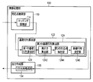
- FIG. 1 is a block diagram illustrating a configuration example of an image processing apparatus according to the first embodiment.
- FIG. 2 is a block diagram illustrating a configuration example of the basic matrix calculation unit according to the first embodiment.
- FIG. 3 is a block diagram illustrating a configuration example of the first basic matrix calculation unit according to the first embodiment.
- FIG. 4 is a block diagram illustrating a configuration example of the image processing unit according to the first embodiment.
- FIG. 5 is a flowchart illustrating an example of a shake correction process according to the first embodiment.
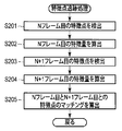
- FIG. 6 is a flowchart showing an example of the feature point tracking process according to the first embodiment.
- FIG. 1 is a block diagram illustrating a configuration example of an image processing apparatus according to the first embodiment.
- FIG. 2 is a block diagram illustrating a configuration example of the basic matrix calculation unit according to the first embodiment.
- FIG. 3 is a block diagram illustrating a configuration example of the first basic matrix calculation unit according to the first embodiment.
- FIG. 4 is a
- FIG. 7A is a diagram for explaining the feature point tracking processing according to the first embodiment, and is a schematic diagram illustrating an image example of an Nth frame to be processed.
- FIG. 7B is a diagram for explaining the feature point tracking processing according to the first embodiment, and is a schematic diagram illustrating an image example of an N + 1th frame to be processed.
- FIG. 8A is a diagram for explaining the feature point tracking process according to the first embodiment, and is a schematic diagram illustrating an example of a feature point in an N-th frame image to be processed.
- FIG. 8B is a diagram for explaining the feature point tracking process according to the first embodiment, and is a schematic diagram illustrating an example of the feature point in the image of the N + 1th frame to be processed.
- FIG. 9 is a diagram for explaining the feature point tracking processing according to the first embodiment, and is a schematic diagram illustrating an example of correspondence of feature points in the processing target image.
- FIG. 10 is a flowchart illustrating an example of posture estimation processing according to the first embodiment.
- FIG. 11 is a flowchart illustrating an example of a first basic matrix calculation process according to the first embodiment.
- FIG. 12 is a flowchart illustrating an example of the inlier number calculation process according to the first embodiment.
- FIG. 13 is a diagram for explaining the posture estimation process according to the first embodiment, and is a diagram illustrating an example of the relationship of the number of inlier corresponding points to the depth.
- FIG. 14 is a block diagram illustrating a configuration example of a digital camera including the image processing apparatus according to the second embodiment.
- FIG. 15 is a block diagram illustrating a configuration example of an image processing unit according to the third embodiment.
- FIG. 10 An outline of a configuration example of the image processing apparatus 10 according to the present embodiment is shown in FIG.
- the image processing apparatus 10 performs processing on the input image information including a plurality of images, calculates information related to the difference in the position and orientation of the camera that acquired each image, and uses the difference information Is a device that outputs.
- the image processing apparatus 10 includes an image processing unit 100, a control unit 11, an image acquisition unit 12, a compression / decompression unit 13, a first storage unit 14, a second storage unit 15, and an output unit 16. Prepare. Each unit is connected to each other via a bus 17. As will be described in detail later, the image processing unit 100 plays a central role in processing related to the image processing apparatus 10.
- the image processing unit 100 includes a corresponding point acquisition unit 110, a basic matrix calculation unit 122, and an output creation unit 130.
- the corresponding point acquisition unit 110 acquires a plurality of mutually corresponding points as a first corresponding point between a plurality of images acquired from the image acquisition unit 12 and the like and input to the image processing unit 100 via the bus 17. .
- the basic matrix calculation unit 122 calculates a basic matrix that represents the relationship between a plurality of input images. As shown in FIG. 2, the basic matrix calculation unit 122 includes a first basic matrix calculation unit 123 and a second basic matrix calculation unit 124.
- the output creation unit 130 creates output information related to the input image based on the basic matrix calculated by the basic matrix calculation unit 122.
- the control unit 11 includes, for example, a CPU, controls the operation of each unit of the image processing apparatus 10, and performs various calculations.
- the image acquisition unit 12 acquires image information (image data) including a plurality of images (moving images) processed by the image processing apparatus 10.
- the compression / decompression unit 13 compresses and decompresses image information.
- the first storage unit 14 includes, for example, a RAM and performs temporary storage necessary for various processes and calculations.
- the second storage unit 15 includes, for example, a ROM, and stores various programs necessary for control and calculation of the image processing apparatus 10.
- the output unit 16 outputs the output information created by the image processing unit 100.
- storage part 15 were set as another structure in a present Example, it is good also as one memory
- the basic matrix calculation unit 122 will be described in more detail.
- a configuration example of the first basic matrix calculation unit 123 is shown in FIG.
- the first basic matrix calculation unit 123 includes a corresponding point extraction unit 1231, a temporary basic matrix calculation unit 1232, an inlier calculation unit 1233, an iterative determination unit 1234, and a first basic matrix determination. Part 1235.
- the corresponding point extraction unit 1231 randomly extracts, for example, eight points from the first corresponding points acquired by the corresponding point acquisition unit 110.
- the temporary basic matrix calculation unit 1232 calculates a basic matrix based on the eight first corresponding points extracted by the corresponding point extraction unit 1231.
- a basic matrix calculated from eight points extracted at random is referred to as a temporary basic matrix.
- the inlier calculating unit 1233 calculates an epipolar line for each first corresponding point acquired by the corresponding point acquiring unit 110 based on the temporary basic matrix calculated by the temporary basic matrix calculating unit 1232, and the epipolar line and the first The distance to the corresponding point is calculated.
- the inlier calculation unit 1233 determines whether or not the distance from the epipolar line is smaller than a predetermined threshold value for each first corresponding point, and sets the corresponding point less than the predetermined threshold value (or less) as the inlier corresponding point. The number of corresponding points that are inlier corresponding points among the first corresponding points is counted.
- the repetition determination unit 1234 repeats the calculation of the number of inlier corresponding points corresponding to each temporary base matrix, that is, the processing from the corresponding point extraction unit 1231 to the inlier calculation unit 1233 a predetermined number of times or until a predetermined condition is satisfied. And a plurality of provisional basic matrices and the number of inlier corresponding points for the temporary basic matrix.
- the first basic matrix determination unit 1235 compares the number of inlier corresponding points for each temporary basic matrix, and determines the temporary basic matrix having the largest number of inlier corresponding points as the first basic matrix.
- the second basic matrix calculation unit 124 includes a depth calculation unit 1242, a second corresponding point extraction unit 1244, and a basic matrix determination unit 1246.
- the depth calculation unit 1242 restores the three-dimensional coordinates of each inlier corresponding point based on the first basic matrix.
- the second corresponding point extraction unit 1244 extracts eight points from the inlier corresponding points so that the depth in the depth direction becomes deeper. These eight points are referred to as second corresponding points.
- the basic matrix determination unit 1246 calculates a second basic matrix based on the second corresponding points.
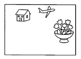
- the image processing apparatus 10 will be specifically described as an apparatus that performs a process of removing blur on an input moving image and outputs a moving image from which the blur has been removed. That is, the image acquisition unit 12 acquires a plurality of image (moving image) data. This image data is an image including subject information as shown in FIG.
- the image processing unit 100 functions as a shake correction unit. An outline of a configuration example of the image processing unit 100 according to this embodiment is shown in FIG.
- the image processing unit 100 includes a corresponding point acquisition unit 110, a posture estimation unit 120 having a basic matrix calculation unit 122, and an output creation unit 130.
- the corresponding point acquisition unit 110 includes a feature point tracking unit 112 that calculates corresponding points based on the feature points in the image acquired by the image acquisition unit 12.
- the feature point tracking unit 112 includes a feature point detection unit 1122, a feature amount calculation unit 1124, and a matching calculation unit 1126.
- the feature point detection unit 1122 receives the image data (moving image) acquired by the image acquisition unit 12 via the bus 17 and receives the Nth frame image and the N + 1th frame image (between consecutive images) of the moving image. ) And feature point candidates are detected.
- the feature amount calculation unit 1124 calculates the feature amount of each feature point candidate detected by the feature point detection unit 1122, and determines a point having a high feature amount as a feature point.
- the matching calculation unit 1126 acquires the correspondence between the feature point of the Nth frame and the feature point of the (N + 1) th frame for the feature point determined by the feature amount calculation unit 1124.
- the feature point for which the correspondence relationship has been acquired will be referred to as a first corresponding point.
- the posture estimation unit 120 includes the basic matrix calculation unit 122, the basic matrix calculation unit 126, and the rotation / translation calculation unit 128 described above.
- the basic matrix calculation unit 126 calculates a basic matrix based on the second basic matrix.
- the rotation / translation calculation unit 128 calculates the rotation and translation of the imaging device that has captured the N + 1th frame relative to the imaging device that has captured the Nth frame, based on the basic matrix.
- the output creation unit 130 includes a correction unit 132 that corrects blurring. Based on the rotation and translation of the imaging device calculated by the posture estimation unit 120, the correction unit 132 performs correction to remove blurring between the Nth frame image and the N + 1th frame image. The output unit 16 outputs a moving image from which blurring has been removed.
- Image data (moving image data) acquired by the image acquisition unit 12 is input to the image processing unit (blur correction unit) 100 via the bus 17.
- the image processing unit (blur correction unit) 100 acquires a moving image and sets a variable N representing a frame number to 1.
- the feature point tracking unit 112 of the image processing unit (blur correction unit) 100 performs a feature point tracking process for tracking the feature points between the Nth frame and the (N + 1) th frame.
- FIG. 7A shows an Nth frame image
- FIG. 7B shows an N + 1th frame image.
- the example shown in this figure is an image of a scene in which there is a flower in the foreground, a house in the back, and an airplane flying.
- the imaging unit that captured them is taken around the right back direction.
- the feature point detection unit 1122 in the feature point tracking unit 112 detects feature point candidates for the Nth frame.
- the feature point detection unit 1122 detects, for example, an object corner or line intersection (corner) in the image as a feature point candidate.
- a generally known method using a Harris operator is used.
- a method using a SUSAN (Smallest Unified Segment Assessing Nucleus) operator that detects an edge may be used.
- the Harris operator and the SUSAN operator are examples, and other approaches may be used.
- the feature amount calculation unit 1124 in the feature point tracking unit 112 calculates the feature amount of each feature point candidate detected in step S201.
- the feature amount is calculated using, for example, a generally known SIFT (Scale Invariant Feature Transform) or SURF (Speeded Up Robust Features). SIFT and SURF are examples, and other methods can be used.
- the feature amount calculation unit 1124 determines a probable feature point among the feature point candidates as the feature point based on the feature amount. For example, when the image of the Nth frame is the image shown in FIG. 7A, as a result of step S202, for example, a feature point as schematically indicated by a circle in FIG. 8A is determined. Normally, the amount of feature points may reach several thousand points, but only a few feature points are illustrated here for simplicity of explanation.
- step S203 the feature point detection unit 1122 in the feature point tracking unit 112 detects feature point candidates for the (N + 1) th frame in the same manner as in step S201.
- step S204 the feature amount calculation unit 1124 calculates the feature amount of the feature point candidate for the (N + 1) th frame as in step S202, and determines the feature point. For example, when the image of the (N + 1) th frame is the image shown in FIG. 7B, as a result of step S204, for example, feature points as schematically indicated by ⁇ marks in FIG. 8B are determined.
- the feature points of the N frame and the feature point of the (N + 1) frame are then detected by the matching calculation unit 1126 in the feature point tracking unit 112 in step S205.
- the correspondence between the feature points of the Nth frame and the (N + 1) th frame is determined.
- corresponding points that have a relationship of being the same point of the subject between images are determined.
- FIGS. 7A and 7B when the correspondence is displayed as a vector in the image of the (N + 1) th frame, the schematic diagram of FIG.
- the feature point at which the correspondence relationship between the Nth frame and the N + 1th frame determined in this way is obtained will be referred to as a first corresponding point.
- the feature point tracking process is sequentially performed while increasing the value of N by 1. Therefore, in the feature point tracking process when N ⁇ 2, the feature points and feature amounts of the Nth frame are calculated during the feature point tracking process of the (N ⁇ 1) th frame.
- the feature point and feature amount of the Nth frame calculated in the feature point tracking process of the N-1 frame may be read.
- the posture estimation unit 120 of the image processing unit (blur correction unit) 100 performs posture estimation processing for estimating the posture of the (N + 1) th frame with respect to the Nth frame.
- the posture estimation process will be described with reference to the flowchart shown in FIG.
- the first basic matrix calculation unit 123 of the posture estimation unit 120 performs a first basic matrix calculation process. This process is performed by a method using, for example, RANSAC (RANdom Sampl Consensus).
- step S401 the corresponding point extraction unit 1231 of the first basic matrix calculation unit 123 sets the first of a plurality of points (eight points in the present embodiment) among the first corresponding points determined by the feature point tracking process. Corresponding points are extracted at random.
- step S402 the temporary base matrix calculation unit 1232 of the first base matrix calculation unit 123 calculates a base matrix using, for example, a known 8-point algorithm based on the extracted first corresponding points of 8 points.
- the basic matrix calculated here will be referred to as a temporary basic matrix.
- step S403 the inlier calculation unit 1233 of the first basic matrix calculation unit 123 performs an inlier number calculation process.
- the inlier number calculation process epipolar geometry related to two images of the Nth frame and the (N + 1) th frame is considered.
- the corresponding point is inlier (highly evaluated).
- the inlier number calculation process the number of corresponding points that are inliers among the plurality of first corresponding points is obtained.
- step S501 the inlier calculation unit 1233 sets a variable I indicating the number of inliers to 8. This is because in the present embodiment, the first corresponding point used for calculating the temporary base matrix is counted as an inlier.
- step S502 the inlier calculation unit 1233 calculates the distance between the epipolar line obtained from the temporary base matrix and each first corresponding point as a target.
- step S503 the inlier calculation unit 1233 determines whether the distance from the epipolar line calculated in step S502 is less than (or may be less than) a predetermined threshold. When it is determined that the distance is less than the threshold, the inlier calculation unit 1233 increases the variable I representing the number of inliers by 1 in step S504. Of the first corresponding points, the corresponding points whose distance from the epipolar line is less than a predetermined threshold will be referred to as inlier corresponding points. Thereafter, the process proceeds to step S505. If it is determined in step S503 that the distance is greater than or equal to a predetermined threshold, the process proceeds to step S505.
- step S505 the inlier calculation unit 1233 determines whether or not the processing in steps S502 to S504 has been performed for all the first corresponding points. When it is determined that the process has not been performed, the process returns to step S502, and the same process is performed for the next first corresponding point. If it is determined in step S505 that the process has been performed, the process returns to the first basic matrix calculation process using the variable I as a return value.
- the number I of first corresponding points that are inliers with respect to the first temporary base matrix among all the first corresponding points is calculated.
- the temporary base matrix having a larger number of inlier corresponding points is a base matrix that appropriately represents the relationship between the Nth frame image and the (N + 1) th frame image.
- step S404 the repetition determination unit 1234 of the first basic matrix calculation unit 123 determines whether or not the processing in steps S401 to S403 has been performed a predetermined number of times. If not, the process returns to step S401. When it is determined in step S404 that the process has been performed a predetermined number of times, the process proceeds to step S405.
- step S405 the first basic matrix determining unit 1235 of the first basic matrix calculating unit 123 determines the temporary basic matrix having the largest number of inlier corresponding points I as the first basic matrix. For the inlier corresponding points in the first basic matrix, corresponding points corresponding to a moving object such as an airplane in FIGS. 7A and 7B are deleted, and corresponding points of a house and a flower that are stationary objects are extracted.
- the number of temporary base matrices for calculating the number of inlier corresponding points determined in step S404 is set to a predetermined number.
- the present invention is not limited to this, and the number of inlier corresponding points may be calculated for the temporary base matrix until a predetermined end condition is satisfied.
- the process returns to the posture estimation process using the first basic matrix as a return value.
- the second basic matrix calculation unit 124 of the posture estimation unit 120 calculates a second basic matrix based on the first basic matrix obtained in the first basic matrix calculation process. . That is, in step S302, the depth calculation unit 1242 of the second basic matrix calculation unit 124 uses the first basic matrix determined by the first basic matrix calculation unit 123 (processing in step S301) to determine the inlier corresponding point. Reconstruct 3D coordinates. In general, it is known that when a basic matrix is used, three-dimensional coordinates corresponding to a space in which an object at each point in an image exists are obtained. As a result, in the case of images such as FIGS.
- 7A and 7B for example, the relationship between the distance representing the depth and the number of inlier corresponding points as shown by the histogram in FIG. 13 is obtained. 7A and 7B, corresponding points detected by the airplane are not inlier corresponding points because the airplane is moving and are not shown in FIG.
- step S303 the second corresponding point extraction unit 1244 of the second basic matrix calculation unit 124 selects (extracts) a plurality (eight points in the present embodiment) of the second corresponding points from the inlier corresponding points.
- the second corresponding point extraction unit 1244 selects an inlier corresponding point with a large depth based on the restored three-dimensional coordinates.
- the second corresponding point extraction unit 1244 selects, for example, four inlier corresponding points closest to the front (most recent) and four inlier corresponding points farthest (most rear) as the second corresponding points. (Extract.
- the corresponding points used for the second corresponding points are not limited to the four inlier corresponding points closest to the front and the four inlier corresponding points farthest away.
- Various extraction methods that increase the depth difference between the second corresponding points may be used. For example, those satisfying the predetermined condition in order from the latest inlier corresponding point may be selectively extracted, and those satisfying the predetermined condition in order from the innermost inlier corresponding point may be selectively extracted.
- the predetermined condition is 4 points from the latest and 4 points from the back, the above-described embodiment is obtained.
- the predetermined condition may be regularly extracted such as first, third, fifth and seventh in order.
- the image plane may be divided into four regions and one point may be extracted from each region.
- four points satisfying the reliability may be extracted sequentially from the front side, and four points satisfying the reliability may be extracted sequentially from the back side.
- a second threshold value that is stricter than the threshold value used in the inlier number calculation process may be used for the determination of reliability. That is, even if the distance between the epipolar line and the inlier corresponding point is smaller than the second threshold value, the foremost four points and the farthest four points are selected as the second corresponding points. Good.
- step S304 the basic matrix determination unit 1246 of the second basic matrix calculation unit 124 calculates a second basic matrix based on the eight second corresponding points selected in step S303.
- the calculation of the second basic matrix is the same as the temporary basic matrix calculation method in step S402.
- step S305 the basic matrix calculation unit 126 of the posture estimation unit 120 calculates a basic matrix based on the second basic matrix. In order to calculate the basic matrix from the basic matrix, a generally known method is used.
- step S306 the rotation / translation calculation unit 128 of the posture estimation unit 120 calculates a rotation matrix and a translation vector based on the basic matrix calculated in step S305.
- this rotation matrix and translation vector represent the difference between the position and orientation of the camera that acquired the Nth frame image and the position and orientation of the camera that acquired the N + 1th frame image. That is, the rotation matrix and the translation vector represent the camera shake amount from which the images from the Nth frame to the N + 1th frame are acquired. Thereafter, the process returns to the blur correction process described with reference to FIG.
- the correction unit 132 of the image processing unit (blur correction unit) 100 calculates a blur correction amount based on the rotation matrix and the translation vector calculated in the posture estimation process. That is, the correction unit 132 of the output generation unit 130 is an image suitable for canceling the camera shake generated between the Nth frame and the (N + 1) th frame obtained as the rotation matrix and the translation vector calculated in step S306. The amount of correction is calculated. At this time, for example, using a low-pass filter, the correction amount is determined so that smooth correction is achieved without performing rapid correction.
- the correction unit 132 performs image conversion based on the correction amount calculated in step S104, and removes image blurring. In this manner, an image from which blurring generated between the Nth frame and the (N + 1) th frame is removed is created.
- step S106 the image processing unit (blur correction unit) 100 determines whether there is a next frame. When it is determined that there is a next frame, the image processing unit (blur correction unit) 100 substitutes N + 1 for a variable N in step S107. Thereafter, the process returns to step S102. When it is determined in step S107 that there is no next frame, the blur correction process ends.
- the image from which the blur is removed is output via the output unit 16. Note that the blur removal process may be sequentially performed for each frame input from the image acquisition unit 12, and images from which blur is removed may be sequentially output from the output unit 16.
- the image acquisition unit 12 functions as an image acquisition unit that acquires a plurality of images.
- the corresponding point acquisition unit 110 functions as a corresponding point acquisition unit that acquires a plurality of first corresponding points corresponding to each other between the plurality of images.
- the first basic matrix calculation unit 123 functions as a first basic matrix calculation unit that calculates a first basic matrix based on a plurality of the first corresponding points.
- the depth calculation unit 1242 functions as a depth calculation unit that calculates depths for the plurality of first corresponding points based on the first basic matrix.
- the second corresponding point extraction unit 1244 functions as a corresponding point extraction unit that extracts a plurality of second corresponding points from the plurality of first corresponding points based on the depth.
- the base matrix determination unit 1246 functions as a base matrix determination unit that calculates a second base matrix based on the plurality of second corresponding points.
- the correction unit 132 functions as a correction unit that corrects a blur existing between the plurality of images based on the second basic matrix.
- the image processing apparatus 10 can remove the blur of the input moving image and output an image without blur.
- the blur is removed based only on the input image, for example, when the image processing apparatus 10 is mounted on a digital camera as a camera shake correction mechanism, no other sensor or drive mechanism is required. .
- the basic matrix cannot be calculated based on corresponding points having no depth in the subject, and the error of the calculated basic matrix is increased and accuracy is increased based on corresponding points having a shallow depth. It is known to decline.
- the three-dimensional coordinates of the subject are restored based on the first basic matrix calculated by a general method, and the second selected so as to increase the depth based on the three-dimensional coordinates.
- a basic matrix is calculated based on the corresponding points. Therefore, compared to the case where the corresponding points used for calculation of the basic matrix are randomly selected and not controlled, for example, when only RANSAC is used, the accuracy of the basic matrix calculated according to the present embodiment is improved. To do.
- blurring is removed based on the difference in images between the Nth frame and the (N + 1) th frame, that is, between adjacent frames.
- the present invention is not limited to this, and blurring may be removed based on image differences between frames that are several frames apart, such as when the difference can be extracted more accurately in images that are several frames apart.
- the feature point tracking unit 112 in the corresponding point acquisition unit 110 matches two images based on the feature points.
- the matching search unit instead of the feature point tracking unit 112, performs matching of two images.
- the matching search unit calculates a corresponding point that functions as a first corresponding point in the first embodiment, for example, by generally known block matching.
- the image processing apparatus 10 operates similarly to the case of the first embodiment, and can obtain the same effect.
- the corresponding point acquisition unit 110 may acquire the corresponding point using any method as long as a corresponding point is obtained between the Nth frame image and the N + 1th frame image.
- any method for acquiring the first corresponding point by the corresponding point acquiring unit 110 any method of feature-based matching or any method of region-based matching may be used. May be used.
- the present embodiment relates to a digital camera 1 including the image processing apparatus 10 of the first embodiment.
- a configuration example of the digital camera 1 according to the present embodiment is shown in FIG.
- the digital camera 1 includes an image processing apparatus 10 having an image processing unit 100 that functions as a blur correction unit.
- the digital camera 1 includes a CPU 20, an imaging optical system 22, an imaging device 24, an AFE (Analog Front End) 26, a signal image processing unit 28, a compression / decompression unit 30, and a RAM (Random Access Memory) 32.
- the CPU 20 functions as a control unit and controls each unit of the digital camera 1.
- the imaging optical system 22 includes a lens, a diaphragm, and the like, and guides the subject image to the imaging element 24.
- the image sensor 24 converts the subject image guided through the imaging optical system 22 into an electrical signal.
- the AFE 26 performs analog signal processing such as correlated double sampling, analog gain control, and A / D conversion.
- the signal image processing unit 28 performs image processing such as color separation, white balance, and gamma conversion on the digital image signal output from the AFE 26.
- the compression / decompression unit 30 compresses or decompresses an image.
- the RAM 32 performs temporary storage necessary for various processes and calculations.
- the ROM 34 stores various programs necessary for the control and calculation of the digital camera 1.
- the operation unit 36 receives an input of an instruction related to the operation of the digital camera 1 from the user.
- the recording unit 38 is detachably connected to the digital camera 1, for example, and records an image acquired by the digital camera 1.
- the display processing unit 40 performs image processing for displaying on the display unit 42.
- the display unit 42 includes, for example, a liquid crystal display and displays the image processed by the display processing unit 40.
- the image signal of the subject that is incident on the image sensor 24 through the imaging optical system 22 and converted into an electrical signal is subjected to image processing by the AFE 26 and the signal image processing unit 28.
- These image signals are sequentially input to the image processing apparatus 10.
- the image processing apparatus 10 sequentially performs the blur correction process described in the first embodiment on the input image.
- the image signal from which the blur is removed is output from the image processing apparatus 10.
- the image signal from which the blur is removed is displayed on the display unit 42 via the display processing unit 40. Further, the image signal from which the blur is removed is recorded in the recording unit 38.
- the blur removal is performed in the image processing apparatus 10 as described in the first embodiment. Therefore, image blurring due to camera shake or the like of the user operating the digital camera 1 is removed, and an image recorded in the recording unit 38 and an image displayed on the display unit 42 are acquired by a camera that does not include the image processing device 10. Higher quality than the rendered image.
- the image processing apparatus 10 is an apparatus that performs three-dimensional reconstruction of a subject based on a plurality of images obtained by photographing the same subject from different directions.
- a configuration example of the image processing unit 100 according to the present embodiment is shown in FIG.
- the corresponding point acquisition unit 110 includes the matching search unit 114 as in the modification of the first embodiment.
- the feature point tracking unit 112 similar to that of the first embodiment may be used.
- the basic matrix calculation unit 122 calculates the second basic matrix as in the case of the first embodiment.
- the output creation unit 130 includes a three-dimensional reconstruction unit 134.
- the three-dimensional reconstruction unit 134 performs three-dimensional reconstruction of the subject based on the second basic matrix.
- the image acquisition unit 12 acquires, for example, two images obtained by photographing the same subject from different directions.
- the corresponding point acquisition unit 110 acquires the first corresponding point of the two images.
- the basic matrix calculation unit 122 calculates a second basic matrix. That is, as in the case of the first embodiment, the first basic matrix calculation unit 123 calculates the first basic matrix based on the first corresponding points acquired by the corresponding point acquisition unit 110.
- the depth calculation unit 1242 of the second basic matrix calculation unit 124 calculates the three-dimensional coordinates of the first corresponding point based on the first basic matrix.
- the second corresponding point extraction unit 1244 extracts the second corresponding point so that the depth becomes deeper based on the three-dimensional coordinates of the first corresponding point.
- the basic matrix determination unit 1246 determines a second basic matrix based on the second corresponding points.
- the three-dimensional reconstruction unit 134 determines the three-dimensional coordinates of each point of the input image using a known method based on the second basic matrix, and performs three-dimensional reconstruction. For example, the three-dimensional reconstruction unit 134 may create a three-dimensional reconstruction image. The result of the three-dimensional reconstruction is output via the output unit 16. Thus, for example, the three-dimensional reconstruction unit 134 functions as a three-dimensional reconstruction unit that performs three-dimensional reconstruction of the subject based on the second basic matrix.
- the image processing apparatus 10 can perform three-dimensional reconstruction based on two images without the position information of the camera that acquired the image. According to the present embodiment, since the basic matrix calculation unit 122 calculates the second basic matrix based on the first basic matrix, the accuracy of the basic matrix obtained is high. Therefore, the image processing apparatus 10 can perform three-dimensional reconstruction with high accuracy.
- the present invention is not limited to the above-described embodiment as it is, and can be embodied by modifying constituent elements without departing from the scope of the invention in the implementation stage.
- various inventions can be formed by appropriately combining a plurality of components disclosed in the embodiment. For example, even if some constituent elements are deleted from all the constituent elements shown in the embodiment, the problem described in the column of problems to be solved by the invention can be solved and the effect of the invention can be obtained. The configuration in which this component is deleted can also be extracted as an invention.
- constituent elements over different embodiments may be appropriately combined.
Abstract
An image processing device (10) comprises: an image acquiring unit (12); a corresponding point acquiring unit (110); a first fundamental matrix calculation unit (123); a depth calculation unit (1242); a corresponding point extraction unit (1244); and a fundamental matrix determination unit (1246). The image acquiring unit (12) acquires a plurality of images. The corresponding point acquiring unit (110) acquires a plurality of first corresponding points corresponding to each other among said images. The first fundamental matrix calculation unit (123) calculates a first fundamental matrix on the basis of said first corresponding points. The depth calculation unit (1242) calculates, based on said first fundamental matrix, the depths corresponding to said first corresponding points. The corresponding point extraction unit (1244) extracts, based on said depths, a plurality of second corresponding points from among said first corresponding points. The fundamental matrix determination unit (1246) calculates a second fundamental matrix on the basis of said second corresponding points.
Description
本発明は、画像処理装置及び画像処理方法に関する。
The present invention relates to an image processing apparatus and an image processing method.
一般に、同一被写体を異なる方向から撮像した複数の画像について、これら画像を取得したカメラの、画像を取得した際の位置及び姿勢の違いは、これら画像に基づいて得られることが知られている。すなわち、画像間の差異に基づいて基礎行列が得られ、この基礎行列に基づいて上述のカメラの位置及び姿勢の関係が算出されることが知られている。例えば日本国特開2008-259076号公報には、複数の画像から算出された基礎行列及びその基礎行列から算出された基本行列に基づいて、これら画像間の動き情報を算出し、この動き情報に基づいて、画像の防振補正を行う技術が開示されている。ここで基礎行列は、対象とする画像間で互いに対応する対応点に基づいて算出されている。
Generally, for a plurality of images obtained by capturing the same subject from different directions, it is known that a difference in position and posture of a camera that has acquired these images can be obtained based on these images. That is, it is known that a basic matrix is obtained based on the difference between images, and the above-described relationship between the position and orientation of the camera is calculated based on this basic matrix. For example, Japanese Patent Application Laid-Open No. 2008-259076 discloses a basic matrix calculated from a plurality of images and motion information between the images based on the basic matrix calculated from the basic matrix. Based on this, a technique for performing image stabilization correction of an image is disclosed. Here, the basic matrix is calculated based on corresponding points corresponding to each other between the target images.
基礎行列を高精度に得るためには、算出に用いる対応点の選択が重要な役割を果たすことが知られている。例えば、その被写体が存在する空間における奥行きがなく平面上に位置する点に相当する画像上の点が対応点として選択された場合、基礎行列は算出され得ない。また、この奥行きが小さい場合、算出される基礎行列の精度は低くなる。
It is known that selection of corresponding points used for calculation plays an important role in obtaining a basic matrix with high accuracy. For example, when a point on the image corresponding to a point located on a plane with no depth in the space where the subject exists is selected as the corresponding point, the basic matrix cannot be calculated. In addition, when the depth is small, the accuracy of the calculated basic matrix is low.
そこで本発明は、精度が高い基礎行列を得ることができる画像処理装置及び画像処理方法を提供することを目的とする。
Therefore, an object of the present invention is to provide an image processing apparatus and an image processing method capable of obtaining a basic matrix with high accuracy.
前記目的を果たすため、本発明の一態様によれば、画像処理装置は、複数の画像を取得する画像取得部と、複数の前記画像間で、互いに対応する複数の第1の対応点を取得する対応点取得部と、複数の前記第1の対応点に基づいて第1の基礎行列を算出する第1の基礎行列算出部と、前記第1の基礎行列に基づいて複数の前記第1の対応点に対する奥行きを算出する奥行き算出部と、前記奥行きに基づいて、複数の前記第1の対応点のうちから複数の第2の対応点を抽出する対応点抽出部と、複数の前記第2の対応点に基づいて第2の基礎行列を算出する基礎行列決定部と、を具備する。
To achieve the above object, according to an aspect of the present invention, an image processing apparatus acquires an image acquisition unit that acquires a plurality of images and a plurality of first corresponding points that correspond to each other between the plurality of images. A corresponding point acquisition unit, a first basic matrix calculation unit that calculates a first basic matrix based on the plurality of first corresponding points, and a plurality of the first basic matrixes based on the first basic matrix A depth calculation unit that calculates a depth for a corresponding point, a corresponding point extraction unit that extracts a plurality of second corresponding points from a plurality of the first corresponding points based on the depth, and a plurality of the second points A basic matrix determination unit that calculates a second basic matrix based on the corresponding points.
前記目的を果たすため、本発明の一態様によれば、撮像装置は、被写体の画像を撮像する撮像部と、同一の前記被写体に関して異なる時間に撮像された複数の前記画像を取得する画像取得部と、複数の前記画像において互いに対応する複数の第1の対応点を取得する対応点取得部と、複数の前記第1の対応点に基づいて第1の基礎行列を算出する第1の基礎行列算出部と、前記第1の基礎行列に基づいて奥行きを算出する奥行き算出部と、前記奥行きに基づいて、複数の前記第1の対応点のうちから複数の第2の対応点を抽出する対応点抽出部と、複数の前記第2の対応点に基づいて第2の基礎行列を算出する基礎行列決定部と、前記第2の基礎行列に基づいて、前記複数の画像の間に存在するブレを補正する補正部と、を具備する。
To achieve the above object, according to one aspect of the present invention, an imaging device includes an imaging unit that captures an image of a subject, and an image acquisition unit that acquires a plurality of the images captured at different times with respect to the same subject. A corresponding point acquisition unit that acquires a plurality of first corresponding points that correspond to each other in the plurality of images, and a first basic matrix that calculates a first basic matrix based on the plurality of first corresponding points A calculating unit; a depth calculating unit for calculating a depth based on the first basic matrix; and a correspondence for extracting a plurality of second corresponding points from the plurality of first corresponding points based on the depth. A point extraction unit; a basic matrix determination unit that calculates a second basic matrix based on the plurality of second corresponding points; and a blur that exists between the plurality of images based on the second basic matrix. And a correction unit for correcting.
前記目的を果たすため、本発明の一態様によれば、画像処理方法は、複数の画像を取得することと、複数の前記画像間で、互いに対応する複数の第1の対応点を取得することと、複数の前記第1の対応点に基づいて第1の基礎行列を算出することと、前記第1の基礎行列に基づいて複数の前記第1の対応点に対する奥行きを算出することと、前記奥行きに基づいて、複数の前記第1の対応点のうちから複数の第2の対応点を抽出することと、複数の前記第2の対応点に基づいて第2の基礎行列を算出することと、を具備する。
To achieve the above object, according to an aspect of the present invention, an image processing method acquires a plurality of images and acquires a plurality of first corresponding points corresponding to each other between the plurality of images. Calculating a first base matrix based on the plurality of first corresponding points; calculating a depth for the plurality of first corresponding points based on the first base matrix; Extracting a plurality of second corresponding points from the plurality of first corresponding points based on the depth; calculating a second base matrix based on the plurality of second corresponding points; Are provided.
前記目的を果たすため、本発明の一態様によれば、コンピュータ読み取り可能な記録媒体は、複数の画像を取得することと、複数の前記画像間で、互いに対応する複数の第1の対応点を取得することと、複数の前記第1の対応点に基づいて第1の基礎行列を算出することと、前記第1の基礎行列に基づいて複数の前記第1の対応点に対する奥行きを算出することと、前記奥行きに基づいて、複数の前記第1の対応点のうちから複数の第2の対応点を抽出することと、複数の前記第2の対応点に基づいて第2の基礎行列を算出することと、をコンピュータに実行させる画像処理プログラムを記録している。
To achieve the above object, according to an aspect of the present invention, a computer-readable recording medium acquires a plurality of images and includes a plurality of first corresponding points corresponding to each other between the plurality of images. Obtaining, calculating a first base matrix based on the plurality of first corresponding points, and calculating depths for the plurality of first corresponding points based on the first base matrix. And extracting a plurality of second corresponding points from the plurality of first corresponding points based on the depth, and calculating a second base matrix based on the plurality of second corresponding points. An image processing program for causing a computer to execute is recorded.
本発明によれば、第1の基礎行列から得られる対応点の奥行きに基づいて、奥行差が大きくなるように選択された対応点を用いて基礎行列が決定されるので、精度が高い基礎行列を得ることができる画像処理装置及び画像処理方法を提供できる。
According to the present invention, since the base matrix is determined using the corresponding points selected so as to increase the depth difference based on the depth of the corresponding points obtained from the first base matrix, the base matrix with high accuracy is obtained. An image processing apparatus and an image processing method can be provided.
[第1の実施形態]
本発明の第1の実施形態について図面を参照して説明する。本実施形態に係る画像処理装置10の構成例の概略を図1に示す。画像処理装置10は、入力された複数の画像を含む画像情報に対して処理を行い、各画像を取得したカメラの位置及び姿勢の差に係る情報を算出し、この差の情報を用いた結果を出力する装置である。 [First Embodiment]
A first embodiment of the present invention will be described with reference to the drawings. An outline of a configuration example of theimage processing apparatus 10 according to the present embodiment is shown in FIG. The image processing apparatus 10 performs processing on the input image information including a plurality of images, calculates information related to the difference in the position and orientation of the camera that acquired each image, and uses the difference information Is a device that outputs.
本発明の第1の実施形態について図面を参照して説明する。本実施形態に係る画像処理装置10の構成例の概略を図1に示す。画像処理装置10は、入力された複数の画像を含む画像情報に対して処理を行い、各画像を取得したカメラの位置及び姿勢の差に係る情報を算出し、この差の情報を用いた結果を出力する装置である。 [First Embodiment]
A first embodiment of the present invention will be described with reference to the drawings. An outline of a configuration example of the
画像処理装置10は、画像処理部100と、制御部11と、画像取得部12と、圧縮伸長部13と、第1の記憶部14と、第2の記憶部15と、出力部16とを備える。各部は、バス17を介して互いに接続されている。画像処理部100は、後に詳述するとおり、この画像処理装置10に係る処理の中心を担う。画像処理部100は、対応点取得部110と、基礎行列算出部122と、出力作成部130とを有する。対応点取得部110は、画像取得部12等から取得され、バス17を介して画像処理部100に入力された複数の画像間で、複数の互いに対応する点を第1の対応点として取得する。基礎行列算出部122は、入力された複数の画像の関係を表す基礎行列を算出する。図2に示されるように、基礎行列算出部122は、第1の基礎行列算出部123と、第2の基礎行列算出部124とを含む。出力作成部130は、基礎行列算出部122が算出した基礎行列に基づいて、入力された画像に係る出力情報を作成する。
The image processing apparatus 10 includes an image processing unit 100, a control unit 11, an image acquisition unit 12, a compression / decompression unit 13, a first storage unit 14, a second storage unit 15, and an output unit 16. Prepare. Each unit is connected to each other via a bus 17. As will be described in detail later, the image processing unit 100 plays a central role in processing related to the image processing apparatus 10. The image processing unit 100 includes a corresponding point acquisition unit 110, a basic matrix calculation unit 122, and an output creation unit 130. The corresponding point acquisition unit 110 acquires a plurality of mutually corresponding points as a first corresponding point between a plurality of images acquired from the image acquisition unit 12 and the like and input to the image processing unit 100 via the bus 17. . The basic matrix calculation unit 122 calculates a basic matrix that represents the relationship between a plurality of input images. As shown in FIG. 2, the basic matrix calculation unit 122 includes a first basic matrix calculation unit 123 and a second basic matrix calculation unit 124. The output creation unit 130 creates output information related to the input image based on the basic matrix calculated by the basic matrix calculation unit 122.
制御部11は、例えばCPUを含み、画像処理装置10の各部の動作を制御し、また各種演算を行う。画像取得部12は、画像処理装置10で処理する複数の画像(動画像)を含む画像情報(画像データ)を取得する。圧縮伸長部13は、画像情報の圧縮及び伸長を行う。第1の記憶部14は、例えばRAMを含み、各種処理及び演算に必要な一時記憶を行う。第2の記憶部15は、例えばROMを含み、画像処理装置10の制御や演算に必要な各種プログラム等を記憶する。出力部16は、画像処理部100で作成された出力情報を出力する。なお、第1の記憶部14と第2の記憶部15は、本実施例においては別構成としたが、1つの記憶部としても構わない。
The control unit 11 includes, for example, a CPU, controls the operation of each unit of the image processing apparatus 10, and performs various calculations. The image acquisition unit 12 acquires image information (image data) including a plurality of images (moving images) processed by the image processing apparatus 10. The compression / decompression unit 13 compresses and decompresses image information. The first storage unit 14 includes, for example, a RAM and performs temporary storage necessary for various processes and calculations. The second storage unit 15 includes, for example, a ROM, and stores various programs necessary for control and calculation of the image processing apparatus 10. The output unit 16 outputs the output information created by the image processing unit 100. In addition, although the 1st memory | storage part 14 and the 2nd memory | storage part 15 were set as another structure in a present Example, it is good also as one memory | storage part.
基礎行列算出部122についてさらに詳細に説明する。第1の基礎行列算出部123の構成例を図3に示す。この図に示すように、第1の基礎行列算出部123は、対応点抽出部1231と、仮基礎行列算出部1232と、インライア算出部1233と、繰り返し判定部1234と、第1の基礎行列決定部1235とを有する。対応点抽出部1231は、対応点取得部110が取得した第1の対応点のうちから、例えば8点をランダムに抽出する。仮基礎行列算出部1232は、対応点抽出部1231により抽出された8点の第1の対応点に基づいて、基礎行列を算出する。ここで、ランダムに抽出された8点から算出した基礎行列を仮基礎行列と称することにする。インライア算出部1233は、対応点取得部110が取得した各第1の対応点について、仮基礎行列算出部1232が算出した仮基礎行列に基づいてエピポーラ線を算出し、このエピポーラ線と当該第1の対応点との距離を算出する。インライア算出部1233は、第1の対応点それぞれに対し、エピポーラ線との距離が所定の閾値より小さいか否かを判断し、所定の閾値未満(以下でもよい)の対応点をインライア対応点とし、第1の対応点のうちインライア対応点となる対応点の数を数える。繰り返し判定部1234は、各仮基礎行列に対応するインライア対応点の数の算出、つまり対応点抽出部1231の処理からインライア算出部1233までの処理を、所定の回数又は所定の条件を満たすまで繰り返させ、複数の仮基礎行列と当該仮基礎行列に対するインライア対応点の数を取得する。第1の基礎行列決定部1235は、各仮基礎行列に対するインライア対応点の数を比較し、最もインライア対応点の数が多い仮基礎行列を第1の基礎行列として決定する。
The basic matrix calculation unit 122 will be described in more detail. A configuration example of the first basic matrix calculation unit 123 is shown in FIG. As shown in this figure, the first basic matrix calculation unit 123 includes a corresponding point extraction unit 1231, a temporary basic matrix calculation unit 1232, an inlier calculation unit 1233, an iterative determination unit 1234, and a first basic matrix determination. Part 1235. The corresponding point extraction unit 1231 randomly extracts, for example, eight points from the first corresponding points acquired by the corresponding point acquisition unit 110. The temporary basic matrix calculation unit 1232 calculates a basic matrix based on the eight first corresponding points extracted by the corresponding point extraction unit 1231. Here, a basic matrix calculated from eight points extracted at random is referred to as a temporary basic matrix. The inlier calculating unit 1233 calculates an epipolar line for each first corresponding point acquired by the corresponding point acquiring unit 110 based on the temporary basic matrix calculated by the temporary basic matrix calculating unit 1232, and the epipolar line and the first The distance to the corresponding point is calculated. The inlier calculation unit 1233 determines whether or not the distance from the epipolar line is smaller than a predetermined threshold value for each first corresponding point, and sets the corresponding point less than the predetermined threshold value (or less) as the inlier corresponding point. The number of corresponding points that are inlier corresponding points among the first corresponding points is counted. The repetition determination unit 1234 repeats the calculation of the number of inlier corresponding points corresponding to each temporary base matrix, that is, the processing from the corresponding point extraction unit 1231 to the inlier calculation unit 1233 a predetermined number of times or until a predetermined condition is satisfied. And a plurality of provisional basic matrices and the number of inlier corresponding points for the temporary basic matrix. The first basic matrix determination unit 1235 compares the number of inlier corresponding points for each temporary basic matrix, and determines the temporary basic matrix having the largest number of inlier corresponding points as the first basic matrix.
第2の基礎行列算出部124は、図2に示されるように、奥行き算出部1242と、第2の対応点抽出部1244と、基礎行列決定部1246とを有する。奥行き算出部1242は、第1の基礎行列に基づいて、各インライア対応点の3次元座標の復元を行う。第2の対応点抽出部1244は、インライア対応点の中から、奥行き方向の深さが深くなるように、8点を抽出する。この8点を第2の対応点と称する。基礎行列決定部1246は、第2の対応点に基づいて第2の基礎行列を算出する。
As shown in FIG. 2, the second basic matrix calculation unit 124 includes a depth calculation unit 1242, a second corresponding point extraction unit 1244, and a basic matrix determination unit 1246. The depth calculation unit 1242 restores the three-dimensional coordinates of each inlier corresponding point based on the first basic matrix. The second corresponding point extraction unit 1244 extracts eight points from the inlier corresponding points so that the depth in the depth direction becomes deeper. These eight points are referred to as second corresponding points. The basic matrix determination unit 1246 calculates a second basic matrix based on the second corresponding points.
このように、インライア対応点から3次元座標を復元することで、正確な対応点からの3次元座標の復元が可能となるため、繰り返し演算をすることなく、正確な第2の対応点の抽出から第2の基礎行列を算出することが可能となる。
Thus, by restoring the 3D coordinates from the inlier corresponding points, it is possible to restore the 3D coordinates from the exact corresponding points, so that the accurate second corresponding points can be extracted without repeated calculations. From this, it is possible to calculate the second basic matrix.
以降、画像処理装置10は、入力された動画像に対してブレを除去する処理を施し、ブレが除去された動画像を出力する装置であるものとして、具体的に説明する。すなわち、画像取得部12は、複数の画像(動画像)データを取得する。この画像データは、後述する図7A等に示されるように被写体の情報を含んだ画像である。画像処理部100は、ブレ補正部として機能する。この実施形態に係る画像処理部100の構成例の概略を図4に示す。画像処理部100は、対応点取得部110と、基礎行列算出部122を有する姿勢推定部120と、出力作成部130とを含む。
Hereinafter, the image processing apparatus 10 will be specifically described as an apparatus that performs a process of removing blur on an input moving image and outputs a moving image from which the blur has been removed. That is, the image acquisition unit 12 acquires a plurality of image (moving image) data. This image data is an image including subject information as shown in FIG. The image processing unit 100 functions as a shake correction unit. An outline of a configuration example of the image processing unit 100 according to this embodiment is shown in FIG. The image processing unit 100 includes a corresponding point acquisition unit 110, a posture estimation unit 120 having a basic matrix calculation unit 122, and an output creation unit 130.
対応点取得部110は、画像取得部12が取得した画像における特徴点に基づいて対応点を算出する特徴点追跡部112を有する。特徴点追跡部112は、特徴点検出部1122と、特徴量算出部1124と、マッチング算出部1126とを有する。特徴点検出部1122は、画像取得部12が取得した画像データ(動画像)を、バス17を介して入力され、当該動画像のNフレーム目の画像とN+1フレーム目の画像(連続する画像間)とのそれぞれの特徴点の候補を検出する。特徴量算出部1124は、特徴点検出部1122で検出された各特徴点の候補の特徴量を算出し、特徴量の高い点を特徴点として決定する。マッチング算出部1126は、特徴量算出部1124によって決定された特徴点について、Nフレーム目の特徴点とN+1フレーム目の特徴点との対応関係を取得する。対応関係が取得された特徴点を第1の対応点と称することにする。
The corresponding point acquisition unit 110 includes a feature point tracking unit 112 that calculates corresponding points based on the feature points in the image acquired by the image acquisition unit 12. The feature point tracking unit 112 includes a feature point detection unit 1122, a feature amount calculation unit 1124, and a matching calculation unit 1126. The feature point detection unit 1122 receives the image data (moving image) acquired by the image acquisition unit 12 via the bus 17 and receives the Nth frame image and the N + 1th frame image (between consecutive images) of the moving image. ) And feature point candidates are detected. The feature amount calculation unit 1124 calculates the feature amount of each feature point candidate detected by the feature point detection unit 1122, and determines a point having a high feature amount as a feature point. The matching calculation unit 1126 acquires the correspondence between the feature point of the Nth frame and the feature point of the (N + 1) th frame for the feature point determined by the feature amount calculation unit 1124. The feature point for which the correspondence relationship has been acquired will be referred to as a first corresponding point.
姿勢推定部120は、上述の基礎行列算出部122と、基本行列算出部126と、回転・並進算出部128とを有する。基本行列算出部126は、第2の基礎行列に基づいて、基本行列を算出する。回転・並進算出部128は、基本行列に基づいて、Nフレーム目を撮影した撮像装置に対するN+1フレーム目を撮影した撮像装置の回転及び並進を算出する。
The posture estimation unit 120 includes the basic matrix calculation unit 122, the basic matrix calculation unit 126, and the rotation / translation calculation unit 128 described above. The basic matrix calculation unit 126 calculates a basic matrix based on the second basic matrix. The rotation / translation calculation unit 128 calculates the rotation and translation of the imaging device that has captured the N + 1th frame relative to the imaging device that has captured the Nth frame, based on the basic matrix.
出力作成部130は、ブレを補正する補正部132を有する。補正部132は、姿勢推定部120が算出した撮像装置の回転及び並進に基づいて、Nフレーム目の画像とN+1フレーム目の画像との間にあるブレを除去する補正を行う。出力部16は、ブレを除去した動画像を出力する。
The output creation unit 130 includes a correction unit 132 that corrects blurring. Based on the rotation and translation of the imaging device calculated by the posture estimation unit 120, the correction unit 132 performs correction to remove blurring between the Nth frame image and the N + 1th frame image. The output unit 16 outputs a moving image from which blurring has been removed.
次に、本実施形態に係る画像処理装置10によるブレの除去に係る動作を説明する。画像処理装置10におけるブレ補正処理を、図5に示すフローチャートを参照して説明する。画像取得部12により取得した画像データ(動画像データ)が、バス17を介して画像処理部(ブレ補正部)100に入力される。ステップS101において画像処理部(ブレ補正部)100は、動画像を取得して、フレームの番号を表す変数Nを1に設定する。ステップS102において画像処理部(ブレ補正部)100の特徴点追跡部112は、Nフレーム目とN+1フレーム目との間の特徴点の追跡を行う特徴点追跡処理を行う。
Next, an operation related to blur removal by the image processing apparatus 10 according to the present embodiment will be described. The blur correction process in the image processing apparatus 10 will be described with reference to the flowchart shown in FIG. Image data (moving image data) acquired by the image acquisition unit 12 is input to the image processing unit (blur correction unit) 100 via the bus 17. In step S101, the image processing unit (blur correction unit) 100 acquires a moving image and sets a variable N representing a frame number to 1. In step S102, the feature point tracking unit 112 of the image processing unit (blur correction unit) 100 performs a feature point tracking process for tracking the feature points between the Nth frame and the (N + 1) th frame.
特徴点追跡処理を図6に示すフローチャート及び図7A乃至9に示す模式図を参照して説明する。ここで図7AはNフレーム目の画像を示し、図7BはN+1フレーム目の画像を示す。この図に示す例は、手前に花があり、奥に家があり、飛行機が飛んでいる場面の画像である。図7A及び7Bの場合、Nフレーム目の画像に対してN+1フレーム目の画像では、これらを撮影した撮像部が右奥方向に回り込んで撮影されている。
Feature point tracking processing will be described with reference to a flowchart shown in FIG. 6 and schematic diagrams shown in FIGS. 7A to 9. Here, FIG. 7A shows an Nth frame image, and FIG. 7B shows an N + 1th frame image. The example shown in this figure is an image of a scene in which there is a flower in the foreground, a house in the back, and an airplane flying. In the case of FIGS. 7A and 7B, in the image of the (N + 1) th frame with respect to the image of the Nth frame, the imaging unit that captured them is taken around the right back direction.
図6に示すように、本発明の特徴点追跡処理では、先ず、ステップS201において特徴点追跡部112内の特徴点検出部1122が、Nフレーム目の特徴点の候補の検出を行う。特徴点検出部1122は、例えば画像における物体の角や線の交わり(コーナー)等を特徴点の候補として検出する。この特徴点の候補の検出には、例えば一般的に知られているHarrisオペレータを用いた方法が利用される。また、例えばエッジを検出するSUSAN(Smallest Univalue Segment Assimilating Nucleus)オペレータを用いた方法が利用されてもよい。HarrisオペレータやSUSANオペレータは一例であり、他の手法も用いられ得る。
As shown in FIG. 6, in the feature point tracking process of the present invention, first, in step S201, the feature point detection unit 1122 in the feature point tracking unit 112 detects feature point candidates for the Nth frame. The feature point detection unit 1122 detects, for example, an object corner or line intersection (corner) in the image as a feature point candidate. For this feature point candidate detection, for example, a generally known method using a Harris operator is used. In addition, for example, a method using a SUSAN (Smallest Unified Segment Assessing Nucleus) operator that detects an edge may be used. The Harris operator and the SUSAN operator are examples, and other approaches may be used.
ステップS202において、特徴点追跡部112内の特徴量算出部1124によって、ステップS201で検出された各特徴点の候補の特徴量を算出する。ここで、特徴量は、例えば一般に知られているSIFT(Scale Invariant Feature Transform)やSURF(Speeded Up Robust Features)を用いて算出される。SIFTやSURFは一例であり、他の手法も用いられ得る。特徴量算出部1124は、特徴量に基づいて、特徴点の候補のうち確からしい特徴点を特徴点として決定する。例えばNフレーム目の画像が図7Aに示された画像の場合、ステップS202の結果、例えば図8Aに模式的に○印で示されるような特徴点が決定される。なお、通常であれば、特徴点の量は数千点にも及ぶことがあるが、ここでは説明を簡単にするため、数点の特徴点のみを例示する。
In step S202, the feature amount calculation unit 1124 in the feature point tracking unit 112 calculates the feature amount of each feature point candidate detected in step S201. Here, the feature amount is calculated using, for example, a generally known SIFT (Scale Invariant Feature Transform) or SURF (Speeded Up Robust Features). SIFT and SURF are examples, and other methods can be used. The feature amount calculation unit 1124 determines a probable feature point among the feature point candidates as the feature point based on the feature amount. For example, when the image of the Nth frame is the image shown in FIG. 7A, as a result of step S202, for example, a feature point as schematically indicated by a circle in FIG. 8A is determined. Normally, the amount of feature points may reach several thousand points, but only a few feature points are illustrated here for simplicity of explanation.
ステップS203において、特徴点追跡部112内の特徴点検出部1122によって、N+1フレーム目の特徴点の候補の検出を、ステップS201の場合と同様に行う。ステップS204において、特徴量算出部1124は、ステップS202の場合と同様にN+1フレーム目の特徴点の候補の特徴量を算出し、特徴点を決定する。例えば、N+1フレーム目の画像が図7Bに示された画像の場合、ステップS204の結果、例えば図8Bに模式的に△印で示されるような特徴点が決定される。
In step S203, the feature point detection unit 1122 in the feature point tracking unit 112 detects feature point candidates for the (N + 1) th frame in the same manner as in step S201. In step S204, the feature amount calculation unit 1124 calculates the feature amount of the feature point candidate for the (N + 1) th frame as in step S202, and determines the feature point. For example, when the image of the (N + 1) th frame is the image shown in FIG. 7B, as a result of step S204, for example, feature points as schematically indicated by Δ marks in FIG. 8B are determined.
これらNフレームの特徴点とN+1フレームの特徴点が決定された後、次に、ステップS205において、特徴点追跡部112内のマッチング算出部1126によって、Nフレーム目とN+1フレーム目との特徴点及びそれらの特徴量を用いて、Nフレーム目とN+1フレーム目との特徴点の対応関係を決定する。つまり、画像間で被写体同一点となる関係にある対応点を決定する。例えば、図7A及び7Bに示されたNフレーム目の画像とN+1フレーム目の画像との場合、対応関係をN+1フレーム目の画像にベクトル表示すると、図9の模式図のようになる。このようにして決定されたNフレーム目とN+1フレーム目との対応関係が得られた特徴点を第1の対応点と称することにする。ステップS205の後、処理は図5を参照して説明しているブレ補正処理に戻る。
After the feature points of the N frame and the feature point of the (N + 1) frame are determined, the feature points of the Nth frame and the (N + 1) th frame are then detected by the matching calculation unit 1126 in the feature point tracking unit 112 in step S205. Using these feature amounts, the correspondence between the feature points of the Nth frame and the (N + 1) th frame is determined. In other words, corresponding points that have a relationship of being the same point of the subject between images are determined. For example, in the case of the image of the Nth frame and the image of the (N + 1) th frame shown in FIGS. 7A and 7B, when the correspondence is displayed as a vector in the image of the (N + 1) th frame, the schematic diagram of FIG. The feature point at which the correspondence relationship between the Nth frame and the N + 1th frame determined in this way is obtained will be referred to as a first corresponding point. After step S205, the process returns to the blur correction process described with reference to FIG.
なお、後述の通り、Nの値を1ずつ増加させながら順に特徴点追跡処理を行う。したがって、N≧2における特徴点追跡処理においては、Nフレーム目の特徴点及び特徴量は、N-1フレーム目の特徴点追跡処理の際に算出されている。ステップS201及びステップS202では、N-1フレームの特徴点追跡処理において算出されたNフレーム目の特徴点と特徴量とを読み出してもよい。
As will be described later, the feature point tracking process is sequentially performed while increasing the value of N by 1. Therefore, in the feature point tracking process when N ≧ 2, the feature points and feature amounts of the Nth frame are calculated during the feature point tracking process of the (N−1) th frame. In step S201 and step S202, the feature point and feature amount of the Nth frame calculated in the feature point tracking process of the N-1 frame may be read.
図5に戻って説明を続ける。ステップS103において画像処理部(ブレ補正部)100の姿勢推定部120は、Nフレーム目に対するN+1フレーム目の姿勢を推定する姿勢推定処理を行う。姿勢推定処理を図10に示すフローチャートを参照して説明する。ステップS301において姿勢推定部120の第1の基礎行列算出部123は、第1の基礎行列算出処理を行う。この処理は、例えばRANSAC(RANdom SAmple Consensus)を用いた方法で行われる。
Referring back to FIG. In step S103, the posture estimation unit 120 of the image processing unit (blur correction unit) 100 performs posture estimation processing for estimating the posture of the (N + 1) th frame with respect to the Nth frame. The posture estimation process will be described with reference to the flowchart shown in FIG. In step S301, the first basic matrix calculation unit 123 of the posture estimation unit 120 performs a first basic matrix calculation process. This process is performed by a method using, for example, RANSAC (RANdom Sampl Consensus).
この第1の基礎行列算出処理を図11に示すフローチャートを参照して説明する。ステップS401において、第1の基礎行列算出部123の対応点抽出部1231は、特徴点追跡処理で決定された第1の対応点のうち、複数点(本実施形態では8点)の第1の対応点をランダムに抽出する。ステップS402において、第1の基礎行列算出部123の仮基礎行列算出部1232は、抽出した8点の第1の対応点に基づいて、例えば公知の8点アルゴリズムを用いて基礎行列を算出する。ここで算出された基礎行列を仮基礎行列と称することにする。
The first basic matrix calculation process will be described with reference to the flowchart shown in FIG. In step S401, the corresponding point extraction unit 1231 of the first basic matrix calculation unit 123 sets the first of a plurality of points (eight points in the present embodiment) among the first corresponding points determined by the feature point tracking process. Corresponding points are extracted at random. In step S402, the temporary base matrix calculation unit 1232 of the first base matrix calculation unit 123 calculates a base matrix using, for example, a known 8-point algorithm based on the extracted first corresponding points of 8 points. The basic matrix calculated here will be referred to as a temporary basic matrix.
ステップS403において、第1の基礎行列算出部123のインライア算出部1233は、インライア個数算出処理を行う。インライア個数算出処理では、Nフレーム目とN+1フレーム目との2枚の画像に係るエピポーラ幾何を考える。このとき、特徴点追跡処理で求まった各第1の対応点について、仮基礎行列から求まるエピポーラ線(評価線)との距離が所定の閾値より小さいとき、その対応点をインライア(評価が高い)とする。インライア個数算出処理では、複数の第1の対応点のうちインライアである対応点の個数が求められる。
In step S403, the inlier calculation unit 1233 of the first basic matrix calculation unit 123 performs an inlier number calculation process. In the inlier number calculation process, epipolar geometry related to two images of the Nth frame and the (N + 1) th frame is considered. At this time, for each first corresponding point obtained by the feature point tracking process, when the distance from the epipolar line (evaluation line) obtained from the temporary basic matrix is smaller than a predetermined threshold, the corresponding point is inlier (highly evaluated). And In the inlier number calculation process, the number of corresponding points that are inliers among the plurality of first corresponding points is obtained.
インライア個数算出処理を図12に示すフローチャートを参照して説明する。ステップS501においてインライア算出部1233は、インライアの個数を表す変数Iを8に設定する。これは、本実施形態では仮基礎行列の算出に用いた第1の対応点をインライアとしてカウントするためである。
The inlier number calculation process will be described with reference to the flowchart shown in FIG. In step S501, the inlier calculation unit 1233 sets a variable I indicating the number of inliers to 8. This is because in the present embodiment, the first corresponding point used for calculating the temporary base matrix is counted as an inlier.
続いて特徴点追跡処理で求まった全ての第1の対応点について以下の処理を行う。ステップS502において、インライア算出部1233は、仮基礎行列から求まるエピポーラ線と対象とする各第1の対応点との距離を算出する。ステップS503において、インライア算出部1233は、ステップS502で算出されたエピポーラ線との距離が所定の閾値未満(以下でもよい)であるか否かを判定する。距離が閾値未満であると判定されたとき、ステップS504においてインライア算出部1233は、インライアの個数を表す変数Iを1増加させる。第1の対応点のうち、エピポーラ線との距離が所定の閾値未満である対応点をインライア対応点と称することにする。その後処理はステップS505に進む。ステップS503の判定で距離が所定の閾値以上であると判定されたとき処理はステップS505に進む。
Subsequently, the following processing is performed for all the first corresponding points obtained by the feature point tracking processing. In step S502, the inlier calculation unit 1233 calculates the distance between the epipolar line obtained from the temporary base matrix and each first corresponding point as a target. In step S503, the inlier calculation unit 1233 determines whether the distance from the epipolar line calculated in step S502 is less than (or may be less than) a predetermined threshold. When it is determined that the distance is less than the threshold, the inlier calculation unit 1233 increases the variable I representing the number of inliers by 1 in step S504. Of the first corresponding points, the corresponding points whose distance from the epipolar line is less than a predetermined threshold will be referred to as inlier corresponding points. Thereafter, the process proceeds to step S505. If it is determined in step S503 that the distance is greater than or equal to a predetermined threshold, the process proceeds to step S505.
ステップS505においてインライア算出部1233は、全ての第1の対応点についてステップS502乃至ステップS504の処理がなされたか否かを判定する。処理がなされていないと判定されたとき、処理はステップS502に戻り、次の第1の対応点について同様の処理を行う。ステップS505の判定において、処理がなされたと判定されたとき、変数Iを戻り値として、処理は第1の基礎行列算出処理に戻る。
In step S505, the inlier calculation unit 1233 determines whether or not the processing in steps S502 to S504 has been performed for all the first corresponding points. When it is determined that the process has not been performed, the process returns to step S502, and the same process is performed for the next first corresponding point. If it is determined in step S505 that the process has been performed, the process returns to the first basic matrix calculation process using the variable I as a return value.
このようにして、全ての第1の対応点のうち第1の仮基礎行列に対してインライアである第1の対応点の個数Iが算出される。ここで、インライア対応点の個数が多い仮基礎行列ほど、Nフレーム目の画像とN+1フレーム目の画像との関係を適切に表す基礎行列であるといえる。
Thus, the number I of first corresponding points that are inliers with respect to the first temporary base matrix among all the first corresponding points is calculated. Here, it can be said that the temporary base matrix having a larger number of inlier corresponding points is a base matrix that appropriately represents the relationship between the Nth frame image and the (N + 1) th frame image.
図11に戻って説明を続ける。ステップS404において第1の基礎行列算出部123の繰り返し判定部1234は、ステップS401乃至ステップS403の処理が所定回数行われたか否かを判定する。所定の回数行われていないとき、処理はステップS401に戻る。ステップS404において所定の回数処理が行われたと判定されたとき、処理はステップS405に進む。ステップS405において第1の基礎行列算出部123の第1の基礎行列決定部1235は、インライア対応点の個数Iが最も大きい仮基礎行列を第1の基礎行列として決定する。この第1の基礎行列におけるインライア対応点は、例えば図7A及び7Bにおける飛行機のような動体に対応する対応点は削除され、静止物体である家及び花の対応点が抽出されることになる。
Referring back to FIG. In step S404, the repetition determination unit 1234 of the first basic matrix calculation unit 123 determines whether or not the processing in steps S401 to S403 has been performed a predetermined number of times. If not, the process returns to step S401. When it is determined in step S404 that the process has been performed a predetermined number of times, the process proceeds to step S405. In step S405, the first basic matrix determining unit 1235 of the first basic matrix calculating unit 123 determines the temporary basic matrix having the largest number of inlier corresponding points I as the first basic matrix. For the inlier corresponding points in the first basic matrix, corresponding points corresponding to a moving object such as an airplane in FIGS. 7A and 7B are deleted, and corresponding points of a house and a flower that are stationary objects are extracted.
ここでは、ステップS404の判断によるインライア対応点の個数を算出する仮基礎行列の数を所定数としている。しかしながらこれに限らず、所定の終了条件が満たされるまで、仮基礎行列についてインライア対応点の個数を算出するようにしてもよい。ステップS405の後、処理は第1の基礎行列を戻り値として姿勢推定処理に戻る。
Here, the number of temporary base matrices for calculating the number of inlier corresponding points determined in step S404 is set to a predetermined number. However, the present invention is not limited to this, and the number of inlier corresponding points may be calculated for the temporary base matrix until a predetermined end condition is satisfied. After step S405, the process returns to the posture estimation process using the first basic matrix as a return value.
図10に戻って説明を続ける。ステップS302乃至ステップS304において、姿勢推定部120の第2の基礎行列算出部124は、第1の基礎行列算出処理で求められた第1の基礎行列に基づいて、第2の基礎行列を算出する。すなわち、ステップS302において、第2の基礎行列算出部124の奥行き算出部1242は、第1の基礎行列算出部123(ステップS301の処理)で決定した第1の基礎行列を用いてインライア対応点の3次元の座標の復元を行う。一般に基礎行列を用いると、画像中の各点の被写体が存在する空間に対応する3次元座標が求まることが知られている。その結果、例えば図7A及び7Bのような画像の場合、図13にヒストグラムで示すような、奥行きを表す距離とインライア対応点の個数との関係が得られる。なお、図7A及び7Bにおいて飛行機に検出された対応点は、飛行機が移動しているためインライア対応点とはならず図13には示されていない。
Referring back to FIG. In steps S302 to S304, the second basic matrix calculation unit 124 of the posture estimation unit 120 calculates a second basic matrix based on the first basic matrix obtained in the first basic matrix calculation process. . That is, in step S302, the depth calculation unit 1242 of the second basic matrix calculation unit 124 uses the first basic matrix determined by the first basic matrix calculation unit 123 (processing in step S301) to determine the inlier corresponding point. Reconstruct 3D coordinates. In general, it is known that when a basic matrix is used, three-dimensional coordinates corresponding to a space in which an object at each point in an image exists are obtained. As a result, in the case of images such as FIGS. 7A and 7B, for example, the relationship between the distance representing the depth and the number of inlier corresponding points as shown by the histogram in FIG. 13 is obtained. 7A and 7B, corresponding points detected by the airplane are not inlier corresponding points because the airplane is moving and are not shown in FIG.
ステップS303において第2の基礎行列算出部124の第2の対応点抽出部1244は、インライア対応点の中から複数(本実施形態では8点)の第2の対応点を選択(抽出)する。このステップS303による選択において、第2の対応点抽出部1244は、復元した3次元座標に基づいて、奥行きが離れたインライア対応点を選択する。第2の対応点抽出部1244は、例えば最も手前側(最近)の近い4点のインライア対応点と、最も奥側(最奥)の遠い4点のインライア対応点を第2の対応点として選択(抽出)する。
In step S303, the second corresponding point extraction unit 1244 of the second basic matrix calculation unit 124 selects (extracts) a plurality (eight points in the present embodiment) of the second corresponding points from the inlier corresponding points. In the selection in step S303, the second corresponding point extraction unit 1244 selects an inlier corresponding point with a large depth based on the restored three-dimensional coordinates. The second corresponding point extraction unit 1244 selects, for example, four inlier corresponding points closest to the front (most recent) and four inlier corresponding points farthest (most rear) as the second corresponding points. (Extract.
なお、第2の対応点に用いる対応点は、最も手前側の近い4点のインライア対応点と、最も奥側の遠い4点のインライア対応点とに限定されない。第2の対応点の奥行き差が大きくなる種々の抽出方法が用いられ得る。例えば、最近のインライア対応点から順に所定の条件を満たすものが選択的に抽出され、さらに最奥のインライア対応点から順に所定の条件を満たすものが選択的に抽出されてもよい。この所定の条件が最近から4点及び最奥から4点であれば、上述の実施形態となる。また、この所定の条件は、例えば順に1,3,5,7番目など規則的に抽出されるものでもよい。また、所定の条件として、例えば画像平面を4つの領域に区切ってそれぞれの領域から1点ずつ抽出されるようにしてもよい。また、手前側から順に信頼性を満たす4点が抽出され、奥側から順に信頼性を満たす4点が抽出されるようにしてもよい。ここで信頼性の判断には、例えばインライア個数算出処理で用いた閾値よりも厳しい第2の閾値が用いられてもよい。すなわち、エピポーラ線とインライア対応点との距離がこの第2の閾値よりも小さいものであって、最も手前側の4点と最も奥側の4点とが第2の対応点として選択されてもよい。また、奥行き方向に離れているだけでなく、画像平面において離れた点を用いることが好ましい。信頼性が判断され、また、画像平面において離れた点が用いられるようにすると、後述の得られる第2の基礎行列の精度がより向上する。また、第2の対応点は、手前側と奥側とそれぞれ4点でなくてもよい。ただし、第2の対応点は、手前側と奥側とそれぞれ4点であることが好ましい。
Note that the corresponding points used for the second corresponding points are not limited to the four inlier corresponding points closest to the front and the four inlier corresponding points farthest away. Various extraction methods that increase the depth difference between the second corresponding points may be used. For example, those satisfying the predetermined condition in order from the latest inlier corresponding point may be selectively extracted, and those satisfying the predetermined condition in order from the innermost inlier corresponding point may be selectively extracted. If the predetermined condition is 4 points from the latest and 4 points from the back, the above-described embodiment is obtained. Further, the predetermined condition may be regularly extracted such as first, third, fifth and seventh in order. Further, as the predetermined condition, for example, the image plane may be divided into four regions and one point may be extracted from each region. Alternatively, four points satisfying the reliability may be extracted sequentially from the front side, and four points satisfying the reliability may be extracted sequentially from the back side. Here, for example, a second threshold value that is stricter than the threshold value used in the inlier number calculation process may be used for the determination of reliability. That is, even if the distance between the epipolar line and the inlier corresponding point is smaller than the second threshold value, the foremost four points and the farthest four points are selected as the second corresponding points. Good. In addition, it is preferable to use points that are not only separated in the depth direction but also separated in the image plane. If the reliability is determined and a distant point is used in the image plane, the accuracy of a second basic matrix obtained later is further improved. Further, the second corresponding points may not be four points on the near side and the far side. However, it is preferable that the second corresponding points are four points each on the near side and the far side.
ステップS304において第2の基礎行列算出部124の基礎行列決定部1246は、ステップS303で選択された8点の第2の対応点に基づいて、第2の基礎行列を算出する。第2の基礎行列の算出は、ステップS402における仮基礎行列の算出手法と同様である。ステップS305において姿勢推定部120の基本行列算出部126は、第2の基礎行列に基づいて、基本行列を算出する。基礎行列から基本行列を算出するには、一般に知られている手法が用いられる。ステップS306において、姿勢推定部120の回転・並進算出部128は、ステップS305で算出された基本行列に基づいて回転行列及び並進ベクトルを算出する。ここで、この回転行列及び並進ベクトルは、Nフレーム目の画像を取得したカメラの位置及び姿勢とN+1フレーム目の画像を取得したカメラの位置及び姿勢との差を表す。すなわち、この回転行列及び並進ベクトルは、Nフレーム目の画像を取得してからN+1フレーム目の画像を取得するまでのそれら画像を取得したカメラブレ量を表す。その後、処理は図5を参照して説明しているブレ補正処理に戻る。
In step S304, the basic matrix determination unit 1246 of the second basic matrix calculation unit 124 calculates a second basic matrix based on the eight second corresponding points selected in step S303. The calculation of the second basic matrix is the same as the temporary basic matrix calculation method in step S402. In step S305, the basic matrix calculation unit 126 of the posture estimation unit 120 calculates a basic matrix based on the second basic matrix. In order to calculate the basic matrix from the basic matrix, a generally known method is used. In step S306, the rotation / translation calculation unit 128 of the posture estimation unit 120 calculates a rotation matrix and a translation vector based on the basic matrix calculated in step S305. Here, this rotation matrix and translation vector represent the difference between the position and orientation of the camera that acquired the Nth frame image and the position and orientation of the camera that acquired the N + 1th frame image. That is, the rotation matrix and the translation vector represent the camera shake amount from which the images from the Nth frame to the N + 1th frame are acquired. Thereafter, the process returns to the blur correction process described with reference to FIG.
図5に戻って説明を続ける。ステップS104において、画像処理部(ブレ補正部)100の補正部132は、姿勢推定処理で算出された回転行列及び並進ベクトルに基づいてブレの補正量を算出する。すなわち、出力作成部130の補正部132は、ステップS306で算出された回転行列及び並進ベクトルとして求まったNフレーム目とN+1フレーム目との間に生じたカメラのブレを相殺するために適切な画像の補正量を算出する。この際、例えばローパスフィルタ等を用いて、急激な補正が行われずに滑らかな補正となるように補正量は決定される。ステップS105において補正部132は、ステップS104で算出した補正量に基づいて画像変換を行い、画像のブレを除去する。このようにして、Nフレーム目とN+1フレーム目との間に生じたブレが除去された画像が作成される。
Referring back to FIG. In step S104, the correction unit 132 of the image processing unit (blur correction unit) 100 calculates a blur correction amount based on the rotation matrix and the translation vector calculated in the posture estimation process. That is, the correction unit 132 of the output generation unit 130 is an image suitable for canceling the camera shake generated between the Nth frame and the (N + 1) th frame obtained as the rotation matrix and the translation vector calculated in step S306. The amount of correction is calculated. At this time, for example, using a low-pass filter, the correction amount is determined so that smooth correction is achieved without performing rapid correction. In step S105, the correction unit 132 performs image conversion based on the correction amount calculated in step S104, and removes image blurring. In this manner, an image from which blurring generated between the Nth frame and the (N + 1) th frame is removed is created.
ステップS106において画像処理部(ブレ補正部)100は、次フレームがあるか否かを判定する。次フレームがあると判定されたとき、ステップS107において画像処理部(ブレ補正部)100は、変数NにN+1を代入する。その後処理はステップS102に戻る。ステップS107の判定で次フレームがないと判定されたとき、ブレ補正処理は終了する。ブレが除去された画像は、出力部16を介して出力される。なお、上記のブレ除去処理は、画像取得部12から入力されたフレームごとに順次行われ、ブレが除去された画像が順次出力部16から出力されてもよい。
In step S106, the image processing unit (blur correction unit) 100 determines whether there is a next frame. When it is determined that there is a next frame, the image processing unit (blur correction unit) 100 substitutes N + 1 for a variable N in step S107. Thereafter, the process returns to step S102. When it is determined in step S107 that there is no next frame, the blur correction process ends. The image from which the blur is removed is output via the output unit 16. Note that the blur removal process may be sequentially performed for each frame input from the image acquisition unit 12, and images from which blur is removed may be sequentially output from the output unit 16.
このように、例えば画像取得部12は、複数の画像を取得する画像取得部として機能する。例えば対応点取得部110は、複数の前記画像間で、互いに対応する複数の第1の対応点を取得する対応点取得部として機能する。例えば第1の基礎行列算出部123は、複数の前記第1の対応点に基づいて第1の基礎行列を算出する第1の基礎行列算出部として機能する。例えば奥行き算出部1242は、前記第1の基礎行列に基づいて複数の前記第1の対応点に対する奥行きを算出する奥行き算出部として機能する。例えば第2の対応点抽出部1244は、前記奥行きに基づいて、複数の前記第1の対応点のうちから複数の第2の対応点を抽出する対応点抽出部として機能する。例えば基礎行列決定部1246は、複数の前記第2の対応点に基づいて第2の基礎行列を算出する基礎行列決定部として機能する。例えば補正部132は、前記第2の基礎行列に基づいて、前記複数の画像の間に存在するブレを補正する補正部として機能する。
Thus, for example, the image acquisition unit 12 functions as an image acquisition unit that acquires a plurality of images. For example, the corresponding point acquisition unit 110 functions as a corresponding point acquisition unit that acquires a plurality of first corresponding points corresponding to each other between the plurality of images. For example, the first basic matrix calculation unit 123 functions as a first basic matrix calculation unit that calculates a first basic matrix based on a plurality of the first corresponding points. For example, the depth calculation unit 1242 functions as a depth calculation unit that calculates depths for the plurality of first corresponding points based on the first basic matrix. For example, the second corresponding point extraction unit 1244 functions as a corresponding point extraction unit that extracts a plurality of second corresponding points from the plurality of first corresponding points based on the depth. For example, the base matrix determination unit 1246 functions as a base matrix determination unit that calculates a second base matrix based on the plurality of second corresponding points. For example, the correction unit 132 functions as a correction unit that corrects a blur existing between the plurality of images based on the second basic matrix.
本実施形態によれば画像処理装置10は、入力された動画像のブレを除去し、ブレのない画像を出力することができる。本実施形態では、入力画像のみに基づいてブレの除去が行われるので、例えば手振れ補正機構として画像処理装置10がデジタルカメラに実装される場合などに、他のセンサや駆動機構などを必要としない。
According to this embodiment, the image processing apparatus 10 can remove the blur of the input moving image and output an image without blur. In the present embodiment, since the blur is removed based only on the input image, for example, when the image processing apparatus 10 is mounted on a digital camera as a camera shake correction mechanism, no other sensor or drive mechanism is required. .
一般に、画像から基礎行列を求める際に、被写体における奥行きがない対応点に基づくと基礎行列は算出され得ず、また奥行きが浅い対応点に基づくと算出される基礎行列の誤差は大きくなり精度が低下することが知られている。本実施形態によれば、一般的な手法で算出された第1の基礎行列に基づいて被写体の3次元座標が復元され、この3次元座標に基づいて奥行きが深くなるように選択された第2の対応点に基づいて基礎行列が算出される。したがって、例えばRANSACのみを用いるときのように基礎行列の算出に用いられる対応点がランダムに選択されて制御がされない場合に比較して、本実施形態によれば算出される基礎行列の精度が向上する。
In general, when obtaining a basic matrix from an image, the basic matrix cannot be calculated based on corresponding points having no depth in the subject, and the error of the calculated basic matrix is increased and accuracy is increased based on corresponding points having a shallow depth. It is known to decline. According to the present embodiment, the three-dimensional coordinates of the subject are restored based on the first basic matrix calculated by a general method, and the second selected so as to increase the depth based on the three-dimensional coordinates. A basic matrix is calculated based on the corresponding points. Therefore, compared to the case where the corresponding points used for calculation of the basic matrix are randomly selected and not controlled, for example, when only RANSAC is used, the accuracy of the basic matrix calculated according to the present embodiment is improved. To do.
なお、本実施形態では、Nフレーム目とN+1フレーム目との間の、すなわち隣接するフレーム間の画像の差異に基づいてブレを除去する例が示されている。しかしながらこれに限らず、数フレーム離れた画像の方が、その差異を精度よく抽出できる場合など、数フレーム離れたフレーム間の画像の差異に基づいてブレを除去してもよい。
In the present embodiment, an example is shown in which blurring is removed based on the difference in images between the Nth frame and the (N + 1) th frame, that is, between adjacent frames. However, the present invention is not limited to this, and blurring may be removed based on image differences between frames that are several frames apart, such as when the difference can be extracted more accurately in images that are several frames apart.
[第1の実施形態の変形例]
第1の実施形態の変形例について説明する。ここでは、第1の実施形態との相違点について説明し、同一の部分については、同一の符号を付してその説明を省略する。第1の実施形態では、対応点取得部110内の特徴点追跡部112が特徴点に基づいて2画像のマッチングを行っている。これに対して本変形例では、特徴点追跡部112に代わって、マッチング探索部が2画像のマッチングを行う。マッチング探索部は、例えば一般に知られているブロックマッチングによって、第1の実施形態における第1の対応点として機能する対応点を算出する。 [Modification of First Embodiment]
A modification of the first embodiment will be described. Here, differences from the first embodiment will be described, and the same portions will be denoted by the same reference numerals and description thereof will be omitted. In the first embodiment, the featurepoint tracking unit 112 in the corresponding point acquisition unit 110 matches two images based on the feature points. On the other hand, in this modification, instead of the feature point tracking unit 112, the matching search unit performs matching of two images. The matching search unit calculates a corresponding point that functions as a first corresponding point in the first embodiment, for example, by generally known block matching.
第1の実施形態の変形例について説明する。ここでは、第1の実施形態との相違点について説明し、同一の部分については、同一の符号を付してその説明を省略する。第1の実施形態では、対応点取得部110内の特徴点追跡部112が特徴点に基づいて2画像のマッチングを行っている。これに対して本変形例では、特徴点追跡部112に代わって、マッチング探索部が2画像のマッチングを行う。マッチング探索部は、例えば一般に知られているブロックマッチングによって、第1の実施形態における第1の対応点として機能する対応点を算出する。 [Modification of First Embodiment]
A modification of the first embodiment will be described. Here, differences from the first embodiment will be described, and the same portions will be denoted by the same reference numerals and description thereof will be omitted. In the first embodiment, the feature
その他の構成は、第1の実施形態の場合と同様である。本実施形態によれば画像処理装置10は、第1の実施形態の場合と同様に動作し、同様の効果を得ることができる。このように、対応点取得部110は、Nフレーム目の画像とN+1フレーム目の画像との間で対応する点が得られれば、どのような手法を用いて対応点を取得してもよい。すなわち、対応点取得部110による第1の対応点の取得方法には、特徴ベースマッチングの何れの手法が用いられても、領域ベースマッチングの何れの手法が用いられても、それらの組み合わせの手法が用いられてもよい。
Other configurations are the same as those in the first embodiment. According to the present embodiment, the image processing apparatus 10 operates similarly to the case of the first embodiment, and can obtain the same effect. As described above, the corresponding point acquisition unit 110 may acquire the corresponding point using any method as long as a corresponding point is obtained between the Nth frame image and the N + 1th frame image. In other words, as a method for acquiring the first corresponding point by the corresponding point acquiring unit 110, any method of feature-based matching or any method of region-based matching may be used. May be used.
[第2の実施形態]
第2の実施形態について説明する。ここでは、第1の実施形態との相違点について説明し、同一の部分については、同一の符号を付してその説明を省略する。本実施形態は、第1の実施形態の画像処理装置10を備えるデジタルカメラ1に係る。本実施形態に係るデジタルカメラ1の構成例を図14に示す。デジタルカメラ1は、ブレ補正部として機能する画像処理部100を有する画像処理装置10を備える。また、デジタルカメラ1は、CPU20と、撮像光学系22と、撮像素子24と、AFE(Analog Front End)26と、信号画像処理部28と、圧縮伸長部30と、RAM(Random Access Memory)32と、ROM(Read Only Memory)34と、操作部36と、記録部38と、表示処理部40と、表示部42とを備える。 [Second Embodiment]
A second embodiment will be described. Here, differences from the first embodiment will be described, and the same portions will be denoted by the same reference numerals and description thereof will be omitted. The present embodiment relates to adigital camera 1 including the image processing apparatus 10 of the first embodiment. A configuration example of the digital camera 1 according to the present embodiment is shown in FIG. The digital camera 1 includes an image processing apparatus 10 having an image processing unit 100 that functions as a blur correction unit. The digital camera 1 includes a CPU 20, an imaging optical system 22, an imaging device 24, an AFE (Analog Front End) 26, a signal image processing unit 28, a compression / decompression unit 30, and a RAM (Random Access Memory) 32. A ROM (Read Only Memory) 34, an operation unit 36, a recording unit 38, a display processing unit 40, and a display unit 42.
第2の実施形態について説明する。ここでは、第1の実施形態との相違点について説明し、同一の部分については、同一の符号を付してその説明を省略する。本実施形態は、第1の実施形態の画像処理装置10を備えるデジタルカメラ1に係る。本実施形態に係るデジタルカメラ1の構成例を図14に示す。デジタルカメラ1は、ブレ補正部として機能する画像処理部100を有する画像処理装置10を備える。また、デジタルカメラ1は、CPU20と、撮像光学系22と、撮像素子24と、AFE(Analog Front End)26と、信号画像処理部28と、圧縮伸長部30と、RAM(Random Access Memory)32と、ROM(Read Only Memory)34と、操作部36と、記録部38と、表示処理部40と、表示部42とを備える。 [Second Embodiment]
A second embodiment will be described. Here, differences from the first embodiment will be described, and the same portions will be denoted by the same reference numerals and description thereof will be omitted. The present embodiment relates to a
CPU20は、制御部として機能し、デジタルカメラ1の各部を制御する。撮像光学系22は、レンズや絞り等を含み、被写体像を撮像素子24に導く。撮像素子24は、撮像光学系22を介して導かれた被写体像を電気信号に変換する。AFE26は、相関二重サンプリング、アナログゲインコントロール、A/D変換等のアナログ信号処理を行う。信号画像処理部28は、AFE26から出力されたデジタル画像信号に対して、色分解、ホワイトバランス、ガンマ変換等の画像処理を行う。圧縮伸長部30は、画像の圧縮や伸長等を行う。RAM32は、各種処理及び演算に必要な一時記憶を行う。ROM34は、デジタルカメラ1の制御や演算に必要な各種プログラム等を記憶する。操作部36は、ユーザからのデジタルカメラ1の操作に係る指示の入力を受け付ける。記録部38は、例えばデジタルカメラ1に取り外し可能に接続されており、デジタルカメラ1で取得した画像を記録する。表示処理部40は、表示部42に表示させるための画像処理を行う。表示部42は、例えば液晶ディスプレイ等を含み、表示処理部40で処理された画像を表示する。
The CPU 20 functions as a control unit and controls each unit of the digital camera 1. The imaging optical system 22 includes a lens, a diaphragm, and the like, and guides the subject image to the imaging element 24. The image sensor 24 converts the subject image guided through the imaging optical system 22 into an electrical signal. The AFE 26 performs analog signal processing such as correlated double sampling, analog gain control, and A / D conversion. The signal image processing unit 28 performs image processing such as color separation, white balance, and gamma conversion on the digital image signal output from the AFE 26. The compression / decompression unit 30 compresses or decompresses an image. The RAM 32 performs temporary storage necessary for various processes and calculations. The ROM 34 stores various programs necessary for the control and calculation of the digital camera 1. The operation unit 36 receives an input of an instruction related to the operation of the digital camera 1 from the user. The recording unit 38 is detachably connected to the digital camera 1, for example, and records an image acquired by the digital camera 1. The display processing unit 40 performs image processing for displaying on the display unit 42. The display unit 42 includes, for example, a liquid crystal display and displays the image processed by the display processing unit 40.
撮像光学系22を介して撮像素子24に入射して電気信号に変換された被写体の画像信号は、AFE26及び信号画像処理部28で画像処理される。これらの画像信号は、画像処理装置10に順次入力される。画像処理装置10は、入力された画像に対して順次第1の実施形態で説明したブレ補正処理を行う。ブレの除去がなされた画像の信号は、画像処理装置10から出力される。このブレが除去された画像の信号は、表示処理部40を介して表示部42に表示される。また、ブレが除去された画像信号は、記録部38に記録される。
The image signal of the subject that is incident on the image sensor 24 through the imaging optical system 22 and converted into an electrical signal is subjected to image processing by the AFE 26 and the signal image processing unit 28. These image signals are sequentially input to the image processing apparatus 10. The image processing apparatus 10 sequentially performs the blur correction process described in the first embodiment on the input image. The image signal from which the blur is removed is output from the image processing apparatus 10. The image signal from which the blur is removed is displayed on the display unit 42 via the display processing unit 40. Further, the image signal from which the blur is removed is recorded in the recording unit 38.
本実施形態によれば、画像処理装置10において第1の実施形態で説明したとおりブレの除去が行われる。したがって、デジタルカメラ1を操作するユーザの手振れ等による画像のブレが除去され、記録部38に記録される画像や、表示部42に表示される画像は、画像処理装置10を備えないカメラで取得された画像よりも品質が高い。
According to the present embodiment, the blur removal is performed in the image processing apparatus 10 as described in the first embodiment. Therefore, image blurring due to camera shake or the like of the user operating the digital camera 1 is removed, and an image recorded in the recording unit 38 and an image displayed on the display unit 42 are acquired by a camera that does not include the image processing device 10. Higher quality than the rendered image.
[第3の実施形態]
第3の実施形態について説明する。ここでは、第1の実施形態との相違点について説明し、同一の部分については、同一の符号を付してその説明を省略する。本実施形態に係る画像処理装置10は、同一被写体を異なる方向から撮影した複数の画像に基づいて、その被写体の3次元再構成を行う装置である。本実施形態に係る画像処理部100の構成例を図15に示す。本実施形態において、図15に示す例では対応点取得部110は、第1の実施形態の変形例と同様にマッチング探索部114を有する。マッチング探索部114でなく、第1の実施形態と同様の特徴点追跡部112が用いられてもよい。本実施形態では、マッチング探索部114から出力された対応点に基づいて、基礎行列算出部122は、第1の実施形態の場合と同様に第2の基礎行列を算出する。また、本実施形態では、出力作成部130は、3次元再構成部134を有する。3次元再構成部134は、第2の基礎行列に基づいて、被写体の3次元再構成を行う。 [Third Embodiment]
A third embodiment will be described. Here, differences from the first embodiment will be described, and the same portions will be denoted by the same reference numerals and description thereof will be omitted. Theimage processing apparatus 10 according to the present embodiment is an apparatus that performs three-dimensional reconstruction of a subject based on a plurality of images obtained by photographing the same subject from different directions. A configuration example of the image processing unit 100 according to the present embodiment is shown in FIG. In the present embodiment, in the example illustrated in FIG. 15, the corresponding point acquisition unit 110 includes the matching search unit 114 as in the modification of the first embodiment. Instead of the matching search unit 114, the feature point tracking unit 112 similar to that of the first embodiment may be used. In the present embodiment, based on the corresponding points output from the matching search unit 114, the basic matrix calculation unit 122 calculates the second basic matrix as in the case of the first embodiment. In the present embodiment, the output creation unit 130 includes a three-dimensional reconstruction unit 134. The three-dimensional reconstruction unit 134 performs three-dimensional reconstruction of the subject based on the second basic matrix.
第3の実施形態について説明する。ここでは、第1の実施形態との相違点について説明し、同一の部分については、同一の符号を付してその説明を省略する。本実施形態に係る画像処理装置10は、同一被写体を異なる方向から撮影した複数の画像に基づいて、その被写体の3次元再構成を行う装置である。本実施形態に係る画像処理部100の構成例を図15に示す。本実施形態において、図15に示す例では対応点取得部110は、第1の実施形態の変形例と同様にマッチング探索部114を有する。マッチング探索部114でなく、第1の実施形態と同様の特徴点追跡部112が用いられてもよい。本実施形態では、マッチング探索部114から出力された対応点に基づいて、基礎行列算出部122は、第1の実施形態の場合と同様に第2の基礎行列を算出する。また、本実施形態では、出力作成部130は、3次元再構成部134を有する。3次元再構成部134は、第2の基礎行列に基づいて、被写体の3次元再構成を行う。 [Third Embodiment]
A third embodiment will be described. Here, differences from the first embodiment will be described, and the same portions will be denoted by the same reference numerals and description thereof will be omitted. The
本実施形態に係る画像処理装置10の動作を簡単に説明する。本実施形態では、画像取得部12は、同一被写体を異なる方向から撮影した例えば2枚の画像を取得する。対応点取得部110は、2枚の画像の第1の対応点を取得する。基礎行列算出部122は、第2の基礎行列を算出する。すなわち、第1の実施形態の場合と同様に、第1の基礎行列算出部123は、対応点取得部110が取得した第1の対応点に基づいて、第1の基礎行列を算出する。第2の基礎行列算出部124の奥行き算出部1242は、第1の基礎行列に基づいて、第1の対応点の3次元座標を算出する。第2の対応点抽出部1244は、第1の対応点の3次元座標に基づいて、深さが深くなるように、第2の対応点を抽出する。基礎行列決定部1246は、第2の対応点に基づいて、第2の基礎行列を決定する。
The operation of the image processing apparatus 10 according to this embodiment will be briefly described. In the present embodiment, the image acquisition unit 12 acquires, for example, two images obtained by photographing the same subject from different directions. The corresponding point acquisition unit 110 acquires the first corresponding point of the two images. The basic matrix calculation unit 122 calculates a second basic matrix. That is, as in the case of the first embodiment, the first basic matrix calculation unit 123 calculates the first basic matrix based on the first corresponding points acquired by the corresponding point acquisition unit 110. The depth calculation unit 1242 of the second basic matrix calculation unit 124 calculates the three-dimensional coordinates of the first corresponding point based on the first basic matrix. The second corresponding point extraction unit 1244 extracts the second corresponding point so that the depth becomes deeper based on the three-dimensional coordinates of the first corresponding point. The basic matrix determination unit 1246 determines a second basic matrix based on the second corresponding points.
3次元再構成部134は、第2の基礎行列に基づいて、公知の方法を用いて入力画像の各点の3次元座標を決定し、3次元再構成を行う。例えば3次元再構成部134は、3次元再構成画像を作成してもよい。3次元再構成の結果は、出力部16を介して出力される。このように、例えば3次元再構成部134は、前記第2の基礎行列に基づいて、前記被写体の3次元再構成を行う3次元再構成部として機能する。
The three-dimensional reconstruction unit 134 determines the three-dimensional coordinates of each point of the input image using a known method based on the second basic matrix, and performs three-dimensional reconstruction. For example, the three-dimensional reconstruction unit 134 may create a three-dimensional reconstruction image. The result of the three-dimensional reconstruction is output via the output unit 16. Thus, for example, the three-dimensional reconstruction unit 134 functions as a three-dimensional reconstruction unit that performs three-dimensional reconstruction of the subject based on the second basic matrix.
本実施形態によれば、画像処理装置10は、画像を取得したカメラの位置情報がなくても2枚の画像に基づいて3次元再構成を行うことができる。本実施形態によれば、基礎行列算出部122は、第1の基礎行列に基づいて第2の基礎行列を算出しているので、得られる基礎行列の精度は高い。したがって、画像処理装置10は、高い精度の3次元再構成を行うことができる。
According to this embodiment, the image processing apparatus 10 can perform three-dimensional reconstruction based on two images without the position information of the camera that acquired the image. According to the present embodiment, since the basic matrix calculation unit 122 calculates the second basic matrix based on the first basic matrix, the accuracy of the basic matrix obtained is high. Therefore, the image processing apparatus 10 can perform three-dimensional reconstruction with high accuracy.
なお、本発明は上記実施形態そのままに限定されるものではなく、実施段階ではその要旨を逸脱しない範囲で構成要素を変形して具体化できる。また、上記実施形態に開示されている複数の構成要素の適宜な組み合わせにより、種々の発明を形成できる。例えば、実施形態に示される全構成要素から幾つかの構成要素を削除しても、発明が解決しようとする課題の欄で述べられた課題が解決でき、かつ、発明の効果が得られる場合には、この構成要素が削除された構成も発明として抽出され得る。さらに、異なる実施形態にわたる構成要素を適宜組み合わせてもよい。
Note that the present invention is not limited to the above-described embodiment as it is, and can be embodied by modifying constituent elements without departing from the scope of the invention in the implementation stage. In addition, various inventions can be formed by appropriately combining a plurality of components disclosed in the embodiment. For example, even if some constituent elements are deleted from all the constituent elements shown in the embodiment, the problem described in the column of problems to be solved by the invention can be solved and the effect of the invention can be obtained. The configuration in which this component is deleted can also be extracted as an invention. Furthermore, constituent elements over different embodiments may be appropriately combined.
Claims (10)
- 複数の画像を取得する画像取得部と、
複数の前記画像間で、互いに対応する複数の第1の対応点を取得する対応点取得部と、
複数の前記第1の対応点に基づいて第1の基礎行列を算出する第1の基礎行列算出部と、
前記第1の基礎行列に基づいて複数の前記第1の対応点に対する奥行きを算出する奥行き算出部と、
前記奥行きに基づいて、複数の前記第1の対応点のうちから複数の第2の対応点を抽出する対応点抽出部と、
複数の前記第2の対応点に基づいて第2の基礎行列を算出する基礎行列決定部と、
を具備する画像処理装置。 An image acquisition unit for acquiring a plurality of images;
A corresponding point acquisition unit that acquires a plurality of first corresponding points corresponding to each other between the plurality of images;
A first basic matrix calculation unit for calculating a first basic matrix based on a plurality of the first corresponding points;
A depth calculation unit that calculates depths for the plurality of first corresponding points based on the first basic matrix;
A corresponding point extracting unit that extracts a plurality of second corresponding points from the plurality of first corresponding points based on the depth;
A base matrix determining unit that calculates a second base matrix based on a plurality of the second corresponding points;
An image processing apparatus comprising: - 前記対応点抽出部により抽出される複数の前記第2の対応点は、前記奥行きに基づいて、前記第1の対応点のうちから、最近の対応点から順に選択的に抽出され、さらに最奥の対応点から順に選択的に抽出される
請求項1に記載の画像処理装置。 The plurality of second corresponding points extracted by the corresponding point extracting unit are selectively extracted from the first corresponding points in order from the most recent corresponding point based on the depth, and further to the innermost side. The image processing apparatus according to claim 1, wherein the image processing apparatus is selectively extracted sequentially from corresponding points. - 前記対応点抽出部は、前記第1の基礎行列に基づいて前記第1の対応点の信頼性を評価し、前記信頼性に基づいて前記第2の対応点を抽出する
請求項1又は2に記載の画像処理装置。 The corresponding point extraction unit evaluates the reliability of the first corresponding point based on the first basic matrix, and extracts the second corresponding point based on the reliability. The image processing apparatus described. - 前記対応点抽出部により抽出される複数の前記第2の対応点は、前記奥行きに基づいて、前記第1の対応点のうちから、最近の対応点と最奥の対応点とを含む対応点が抽出される
請求項1又は2に記載の画像処理装置。 The plurality of second corresponding points extracted by the corresponding point extracting unit include corresponding points including the latest corresponding point and the deepest corresponding point among the first corresponding points based on the depth. The image processing apparatus according to claim 1, wherein the image is extracted. - 複数の前記画像は、同一の被写体に関して異なる時間に撮像された画像であり、
前記第2の基礎行列に基づいて、前記複数の画像の間に存在するブレを補正する補正部をさらに具備する
請求項1又は2に記載の画像処理装置。 The plurality of images are images taken at different times with respect to the same subject,
The image processing apparatus according to claim 1, further comprising: a correction unit that corrects a blur existing between the plurality of images based on the second basic matrix. - 前記第2の基礎行列に基づいて、前記画像の3次元再構成を行う3次元再構成部をさらに具備する
請求項1又は2に記載の画像処理装置。 The image processing apparatus according to claim 1, further comprising a three-dimensional reconstruction unit that performs three-dimensional reconstruction of the image based on the second basic matrix. - 前記第1の基礎行列算出部は、前記第1の対応点の中から所定数の対応点をランダムに選択して行う繰り返し演算によって前記第1の基礎行列を算出する請求項1又は2に記載の画像処理装置。 3. The first basic matrix calculation unit according to claim 1, wherein the first basic matrix calculation unit calculates the first basic matrix by an iterative calculation performed by randomly selecting a predetermined number of corresponding points from the first corresponding points. Image processing apparatus.
- 被写体の画像を撮像する撮像部と、
同一の前記被写体に関して異なる時間に撮像された複数の前記画像を取得する画像取得部と、
複数の前記画像において互いに対応する複数の第1の対応点を取得する対応点取得部と、
複数の前記第1の対応点に基づいて第1の基礎行列を算出する第1の基礎行列算出部と、
前記第1の基礎行列に基づいて奥行きを算出する奥行き算出部と、
前記奥行きに基づいて、複数の前記第1の対応点のうちから複数の第2の対応点を抽出する対応点抽出部と、
複数の前記第2の対応点に基づいて第2の基礎行列を算出する基礎行列決定部と、
前記第2の基礎行列に基づいて、前記複数の画像の間に存在するブレを補正する補正部と、
を具備する撮像装置。 An imaging unit that captures an image of a subject;
An image acquisition unit that acquires a plurality of the images captured at different times with respect to the same subject;
A corresponding point acquisition unit that acquires a plurality of first corresponding points corresponding to each other in the plurality of images;
A first basic matrix calculation unit for calculating a first basic matrix based on a plurality of the first corresponding points;
A depth calculation unit for calculating a depth based on the first basic matrix;
A corresponding point extracting unit that extracts a plurality of second corresponding points from the plurality of first corresponding points based on the depth;
A base matrix determining unit that calculates a second base matrix based on a plurality of the second corresponding points;
A correction unit that corrects a blur existing between the plurality of images based on the second basic matrix;
An imaging apparatus comprising: - 複数の画像を取得することと、
複数の前記画像間で、互いに対応する複数の第1の対応点を取得することと、
複数の前記第1の対応点に基づいて第1の基礎行列を算出することと、
前記第1の基礎行列に基づいて複数の前記第1の対応点に対する奥行きを算出することと、
前記奥行きに基づいて、複数の前記第1の対応点のうちから複数の第2の対応点を抽出することと、
複数の前記第2の対応点に基づいて第2の基礎行列を算出することと、
を具備する画像処理方法。 Acquiring multiple images,
Obtaining a plurality of first corresponding points corresponding to each other between the plurality of images;
Calculating a first basis matrix based on a plurality of the first corresponding points;
Calculating a depth for the plurality of first corresponding points based on the first basic matrix;
Extracting a plurality of second corresponding points from the plurality of first corresponding points based on the depth;
Calculating a second base matrix based on a plurality of the second corresponding points;
An image processing method comprising: - 複数の画像を取得することと、
複数の前記画像間で、互いに対応する複数の第1の対応点を取得することと、
複数の前記第1の対応点に基づいて第1の基礎行列を算出することと、
前記第1の基礎行列に基づいて複数の前記第1の対応点に対する奥行きを算出することと、
前記奥行きに基づいて、複数の前記第1の対応点のうちから複数の第2の対応点を抽出することと、
複数の前記第2の対応点に基づいて第2の基礎行列を算出することと、
をコンピュータに実行させるためのプログラムを記録したコンピュータ読み取り可能な記録媒体。 Acquiring multiple images,
Obtaining a plurality of first corresponding points corresponding to each other between the plurality of images;
Calculating a first basis matrix based on a plurality of the first corresponding points;
Calculating a depth for the plurality of first corresponding points based on the first basic matrix;
Extracting a plurality of second corresponding points from the plurality of first corresponding points based on the depth;
Calculating a second base matrix based on a plurality of the second corresponding points;
The computer-readable recording medium which recorded the program for making a computer perform.
Priority Applications (3)
| Application Number | Priority Date | Filing Date | Title |
|---|---|---|---|
| CN201380032255.XA CN104396231B (en) | 2012-06-20 | 2013-02-18 | Image processing apparatus and image processing method |
| US14/573,040 US9760999B2 (en) | 2012-06-20 | 2014-12-17 | Image processing apparatus, imaging apparatus, and image processing method |
| US15/673,961 US10366504B2 (en) | 2012-06-20 | 2017-08-10 | Image processing apparatus and image processing method for performing three-dimensional reconstruction of plurality of images |
Applications Claiming Priority (2)
| Application Number | Priority Date | Filing Date | Title |
|---|---|---|---|
| JP2012-138569 | 2012-06-20 | ||
| JP2012138569A JP5977591B2 (en) | 2012-06-20 | 2012-06-20 | Image processing apparatus, imaging apparatus including the same, image processing method, and computer-readable recording medium recording an image processing program |
Related Child Applications (1)
| Application Number | Title | Priority Date | Filing Date |
|---|---|---|---|
| US14/573,040 Continuation US9760999B2 (en) | 2012-06-20 | 2014-12-17 | Image processing apparatus, imaging apparatus, and image processing method |
Publications (1)
| Publication Number | Publication Date |
|---|---|
| WO2013190862A1 true WO2013190862A1 (en) | 2013-12-27 |
Family
ID=49768472
Family Applications (1)
| Application Number | Title | Priority Date | Filing Date |
|---|---|---|---|
| PCT/JP2013/053883 WO2013190862A1 (en) | 2012-06-20 | 2013-02-18 | Image processing device and image processing method |
Country Status (4)
| Country | Link |
|---|---|
| US (2) | US9760999B2 (en) |
| JP (1) | JP5977591B2 (en) |
| CN (1) | CN104396231B (en) |
| WO (1) | WO2013190862A1 (en) |
Cited By (2)
| Publication number | Priority date | Publication date | Assignee | Title |
|---|---|---|---|---|
| US11013595B2 (en) | 2017-08-11 | 2021-05-25 | Edwards Lifesciences Corporation | Sealing element for prosthetic heart valve |
| CN113160044A (en) * | 2020-01-23 | 2021-07-23 | 百度在线网络技术(北京)有限公司 | Depth image super-resolution method, training device, equipment and medium |
Families Citing this family (11)
| Publication number | Priority date | Publication date | Assignee | Title |
|---|---|---|---|---|
| JP6376873B2 (en) * | 2014-07-16 | 2018-08-22 | キヤノン株式会社 | Image processing apparatus, image processing method, and program |
| JP6336353B2 (en) * | 2014-08-19 | 2018-06-06 | 株式会社オーエム製作所 | Machine Tools |
| KR102281184B1 (en) * | 2014-11-20 | 2021-07-23 | 삼성전자주식회사 | Method and apparatus for calibrating image |
| JP6511980B2 (en) * | 2015-06-19 | 2019-05-15 | カシオ計算機株式会社 | Image processing apparatus, image processing method and program |
| JP6894725B2 (en) * | 2017-03-09 | 2021-06-30 | キヤノン株式会社 | Image processing device and its control method, program, storage medium |
| KR102434574B1 (en) | 2017-08-14 | 2022-08-22 | 삼성전자주식회사 | Method and apparatus for recognizing a subject existed in an image based on temporal movement or spatial movement of a feature point of the image |
| JP2019062340A (en) * | 2017-09-26 | 2019-04-18 | キヤノン株式会社 | Image shake correction apparatus and control method |
| US10594940B1 (en) * | 2018-01-12 | 2020-03-17 | Vulcan Inc. | Reduction of temporal and spatial jitter in high-precision motion quantification systems |
| US11044404B1 (en) | 2018-11-28 | 2021-06-22 | Vulcan Inc. | High-precision detection of homogeneous object activity in a sequence of images |
| US10872400B1 (en) | 2018-11-28 | 2020-12-22 | Vulcan Inc. | Spectral selection and transformation of image frames |
| CN113875221A (en) * | 2019-08-27 | 2021-12-31 | Oppo广东移动通信有限公司 | Image processing method and device, electronic equipment and computer readable storage medium |
Citations (3)
| Publication number | Priority date | Publication date | Assignee | Title |
|---|---|---|---|---|
| JPH11194027A (en) * | 1998-01-07 | 1999-07-21 | Nec Corp | Three-dimensional coordinate measuring instrument |
| JP2004213278A (en) * | 2002-12-27 | 2004-07-29 | Ricoh Co Ltd | Image processing apparatus, image processing method, image processing program, storage medium, and electronic apparatus |
| JP2007256029A (en) * | 2006-03-23 | 2007-10-04 | Denso It Laboratory Inc | Stereo image processing device |
Family Cites Families (34)
| Publication number | Priority date | Publication date | Assignee | Title |
|---|---|---|---|---|
| US5798762A (en) * | 1995-05-10 | 1998-08-25 | Cagent Technologies, Inc. | Controlling a real-time rendering engine using a list-based control mechanism |
| US5748199A (en) * | 1995-12-20 | 1998-05-05 | Synthonics Incorporated | Method and apparatus for converting a two dimensional motion picture into a three dimensional motion picture |
| US6388672B1 (en) * | 1996-02-02 | 2002-05-14 | Kabushiki Kaisha Toshiba | Graphic translate engine, floating point arithmetic unit and floating point multiply-add calculation unit |
| JP3745117B2 (en) * | 1998-05-08 | 2006-02-15 | キヤノン株式会社 | Image processing apparatus and image processing method |
| DE69812591T2 (en) * | 1998-05-20 | 2004-03-25 | Texas Instruments France | Autostereoscopic display device |
| US6525737B1 (en) * | 1998-08-20 | 2003-02-25 | Apple Computer, Inc. | Graphics processor with pipeline state storage and retrieval |
| JP4764169B2 (en) * | 2003-09-10 | 2011-08-31 | シャープ株式会社 | Lens position control device |
| US7343035B1 (en) * | 2003-10-20 | 2008-03-11 | Open Invention Network Llc | Method and system for three-dimensional feature attribution through synergy of rational polynomial coefficients and projective geometry |
| US7929801B2 (en) * | 2005-08-15 | 2011-04-19 | Sony Corporation | Depth information for auto focus using two pictures and two-dimensional Gaussian scale space theory |
| US8197070B2 (en) * | 2006-01-24 | 2012-06-12 | Seiko Epson Corporation | Color-based feature identification |
| WO2007148219A2 (en) * | 2006-06-23 | 2007-12-27 | Imax Corporation | Methods and systems for converting 2d motion pictures for stereoscopic 3d exhibition |
| US9008378B2 (en) * | 2006-12-20 | 2015-04-14 | The Board Of Trustees Of The Leland Stanford Junior University | Arrangement and imaging of biological samples |
| JP4714176B2 (en) * | 2007-03-29 | 2011-06-29 | 富士フイルム株式会社 | Stereoscopic apparatus and optical axis adjustment method |
| JP4958610B2 (en) | 2007-04-06 | 2012-06-20 | キヤノン株式会社 | Image stabilization apparatus, imaging apparatus, and image stabilization method |
| NZ567986A (en) * | 2008-05-02 | 2010-08-27 | Auckland Uniservices Ltd | Real-time stereo image matching system |
| US20100097444A1 (en) * | 2008-10-16 | 2010-04-22 | Peter Lablans | Camera System for Creating an Image From a Plurality of Images |
| US8339616B2 (en) * | 2009-03-31 | 2012-12-25 | Micrometric Vision Technologies | Method and apparatus for high-speed unconstrained three-dimensional digitalization |
| DE102009023896B4 (en) * | 2009-06-04 | 2015-06-18 | Fraunhofer-Gesellschaft zur Förderung der angewandten Forschung e.V. | Apparatus and method for detecting a plant |
| KR20110057629A (en) * | 2009-11-24 | 2011-06-01 | 엘지전자 주식회사 | A method for providing an user interface and a digital broadcast receiver |
| SG172487A1 (en) * | 2009-12-07 | 2011-07-28 | Sony Corp | A three-dimensional imaging apparatus and a method of generating a three-dimensional image of an object |
| US8134719B2 (en) * | 2010-03-19 | 2012-03-13 | Carestream Health, Inc. | 3-D imaging using telecentric defocus |
| US9743020B2 (en) * | 2010-03-23 | 2017-08-22 | California Institute Of Technology | Super resolution optofluidic microscopes for 2D and 3D imaging |
| JP5024410B2 (en) | 2010-03-29 | 2012-09-12 | カシオ計算機株式会社 | 3D modeling apparatus, 3D modeling method, and program |
| JP5467993B2 (en) * | 2010-03-30 | 2014-04-09 | 富士フイルム株式会社 | Image processing apparatus, compound-eye digital camera, and program |
| KR101630307B1 (en) * | 2010-05-12 | 2016-06-14 | 삼성전자주식회사 | A digital photographing apparatus, a method for controlling the same, and a computer-readable storage medium |
| JP5739624B2 (en) * | 2010-07-01 | 2015-06-24 | キヤノン株式会社 | Optical apparatus, imaging apparatus, and control method |
| US9344701B2 (en) * | 2010-07-23 | 2016-05-17 | 3Dmedia Corporation | Methods, systems, and computer-readable storage media for identifying a rough depth map in a scene and for determining a stereo-base distance for three-dimensional (3D) content creation |
| KR101700363B1 (en) * | 2010-09-08 | 2017-01-26 | 삼성전자주식회사 | Digital photographing apparatus and method for controlling the same |
| JP5891424B2 (en) * | 2010-09-17 | 2016-03-23 | パナソニックIpマネジメント株式会社 | 3D image creation apparatus and 3D image creation method |
| JP5917017B2 (en) * | 2011-05-11 | 2016-05-11 | キヤノン株式会社 | Image processing apparatus, control method therefor, and program |
| CN102447927B (en) * | 2011-09-19 | 2013-11-06 | 四川虹微技术有限公司 | Method for warping three-dimensional image with camera calibration parameter |
| CN103297677B (en) * | 2012-02-24 | 2016-07-06 | 卡西欧计算机株式会社 | Generate video generation device and the image generating method of reconstruct image |
| JP5901447B2 (en) * | 2012-06-27 | 2016-04-13 | オリンパス株式会社 | Image processing apparatus, imaging apparatus including the same, image processing method, and image processing program |
| JP5997645B2 (en) * | 2013-03-26 | 2016-09-28 | キヤノン株式会社 | Image processing apparatus and method, and imaging apparatus |
-
2012
- 2012-06-20 JP JP2012138569A patent/JP5977591B2/en active Active
-
2013
- 2013-02-18 CN CN201380032255.XA patent/CN104396231B/en not_active Expired - Fee Related
- 2013-02-18 WO PCT/JP2013/053883 patent/WO2013190862A1/en active Application Filing
-
2014
- 2014-12-17 US US14/573,040 patent/US9760999B2/en active Active
-
2017
- 2017-08-10 US US15/673,961 patent/US10366504B2/en not_active Expired - Fee Related
Patent Citations (3)
| Publication number | Priority date | Publication date | Assignee | Title |
|---|---|---|---|---|
| JPH11194027A (en) * | 1998-01-07 | 1999-07-21 | Nec Corp | Three-dimensional coordinate measuring instrument |
| JP2004213278A (en) * | 2002-12-27 | 2004-07-29 | Ricoh Co Ltd | Image processing apparatus, image processing method, image processing program, storage medium, and electronic apparatus |
| JP2007256029A (en) * | 2006-03-23 | 2007-10-04 | Denso It Laboratory Inc | Stereo image processing device |
Cited By (3)
| Publication number | Priority date | Publication date | Assignee | Title |
|---|---|---|---|---|
| US11013595B2 (en) | 2017-08-11 | 2021-05-25 | Edwards Lifesciences Corporation | Sealing element for prosthetic heart valve |
| CN113160044A (en) * | 2020-01-23 | 2021-07-23 | 百度在线网络技术(北京)有限公司 | Depth image super-resolution method, training device, equipment and medium |
| CN113160044B (en) * | 2020-01-23 | 2023-12-26 | 百度在线网络技术(北京)有限公司 | Depth image super-resolution method, training method and device, equipment and medium |
Also Published As
| Publication number | Publication date |
|---|---|
| CN104396231A (en) | 2015-03-04 |
| JP2014003520A (en) | 2014-01-09 |
| US10366504B2 (en) | 2019-07-30 |
| US20150103145A1 (en) | 2015-04-16 |
| US20170358100A1 (en) | 2017-12-14 |
| JP5977591B2 (en) | 2016-08-24 |
| CN104396231B (en) | 2018-05-01 |
| US9760999B2 (en) | 2017-09-12 |
Similar Documents
| Publication | Publication Date | Title |
|---|---|---|
| JP5977591B2 (en) | Image processing apparatus, imaging apparatus including the same, image processing method, and computer-readable recording medium recording an image processing program | |
| CN110264509B (en) | Method, apparatus, and storage medium for determining pose of image capturing device | |
| US10311595B2 (en) | Image processing device and its control method, imaging apparatus, and storage medium | |
| JP4958610B2 (en) | Image stabilization apparatus, imaging apparatus, and image stabilization method | |
| KR102135770B1 (en) | Method and apparatus for reconstructing 3d face with stereo camera | |
| JP5901447B2 (en) | Image processing apparatus, imaging apparatus including the same, image processing method, and image processing program | |
| JP5803467B2 (en) | Image processing apparatus, imaging apparatus, and image processing method | |
| TW201118791A (en) | System and method for obtaining camera parameters from a plurality of images, and computer program products thereof | |
| KR20130112311A (en) | Apparatus and method for reconstructing dense three dimension image | |
| JP7159384B2 (en) | Image processing device, image processing method, and program | |
| WO2012029658A1 (en) | Imaging device, image-processing device, image-processing method, and image-processing program | |
| CN109636731B (en) | Image smear elimination method, electronic device and storage medium | |
| US11250581B2 (en) | Information processing apparatus, information processing method, and storage medium | |
| CN111476812A (en) | Map segmentation method and device, pose estimation method and equipment terminal | |
| JP6395429B2 (en) | Image processing apparatus, control method thereof, and storage medium | |
| JP6576179B2 (en) | Image processing apparatus, image processing method, and program | |
| JP6601893B2 (en) | Image processing apparatus, image processing method, and program | |
| JP5953142B2 (en) | Image processing apparatus, imaging apparatus including the same, image processing method, and image processing program | |
| JP5478533B2 (en) | Omnidirectional image generation method, image generation apparatus, and program | |
| KR20190129433A (en) | Method for generating panoramic image and apparatus thereof | |
| JP6910622B2 (en) | Image processing system | |
| Xiang et al. | A modified joint trilateral filter based depth map refinement method | |
| JP4920525B2 (en) | Image processing apparatus, image processing method, and image processing program | |
| JP6525693B2 (en) | Image processing apparatus and image processing method | |
| JP2023080290A (en) | Information processing apparatus, control method of the same and program |
Legal Events
| Date | Code | Title | Description |
|---|---|---|---|
| 121 | Ep: the epo has been informed by wipo that ep was designated in this application |
Ref document number: 13807283 Country of ref document: EP Kind code of ref document: A1 |
|
| NENP | Non-entry into the national phase |
Ref country code: DE |
|
| 122 | Ep: pct application non-entry in european phase |
Ref document number: 13807283 Country of ref document: EP Kind code of ref document: A1 |