WO2013190789A1 - Reception device, and synchronous processing method therefor - Google Patents
Reception device, and synchronous processing method therefor Download PDFInfo
- Publication number
- WO2013190789A1 WO2013190789A1 PCT/JP2013/003527 JP2013003527W WO2013190789A1 WO 2013190789 A1 WO2013190789 A1 WO 2013190789A1 JP 2013003527 W JP2013003527 W JP 2013003527W WO 2013190789 A1 WO2013190789 A1 WO 2013190789A1
- Authority
- WO
- WIPO (PCT)
- Prior art keywords
- video
- time code
- time
- stream
- video stream
- Prior art date
Links
Images


Classifications
-
- H—ELECTRICITY
- H04—ELECTRIC COMMUNICATION TECHNIQUE
- H04N—PICTORIAL COMMUNICATION, e.g. TELEVISION
- H04N21/00—Selective content distribution, e.g. interactive television or video on demand [VOD]
- H04N21/40—Client devices specifically adapted for the reception of or interaction with content, e.g. set-top-box [STB]; Operations thereof
- H04N21/43—Processing of content or additional data, e.g. demultiplexing additional data from a digital video stream; Elementary client operations, e.g. monitoring of home network or synchronising decoder's clock; Client middleware
- H04N21/4302—Content synchronisation processes, e.g. decoder synchronisation
- H04N21/4307—Synchronising the rendering of multiple content streams or additional data on devices, e.g. synchronisation of audio on a mobile phone with the video output on the TV screen
- H04N21/43072—Synchronising the rendering of multiple content streams or additional data on devices, e.g. synchronisation of audio on a mobile phone with the video output on the TV screen of multiple content streams on the same device
-
- H—ELECTRICITY
- H04—ELECTRIC COMMUNICATION TECHNIQUE
- H04N—PICTORIAL COMMUNICATION, e.g. TELEVISION
- H04N21/00—Selective content distribution, e.g. interactive television or video on demand [VOD]
- H04N21/40—Client devices specifically adapted for the reception of or interaction with content, e.g. set-top-box [STB]; Operations thereof
- H04N21/43—Processing of content or additional data, e.g. demultiplexing additional data from a digital video stream; Elementary client operations, e.g. monitoring of home network or synchronising decoder's clock; Client middleware
- H04N21/4302—Content synchronisation processes, e.g. decoder synchronisation
- H04N21/4305—Synchronising client clock from received content stream, e.g. locking decoder clock with encoder clock, extraction of the PCR packets
-
- H—ELECTRICITY
- H04—ELECTRIC COMMUNICATION TECHNIQUE
- H04H—BROADCAST COMMUNICATION
- H04H20/00—Arrangements for broadcast or for distribution combined with broadcast
- H04H20/18—Arrangements for synchronising broadcast or distribution via plural systems
-
- H—ELECTRICITY
- H04—ELECTRIC COMMUNICATION TECHNIQUE
- H04N—PICTORIAL COMMUNICATION, e.g. TELEVISION
- H04N21/00—Selective content distribution, e.g. interactive television or video on demand [VOD]
- H04N21/20—Servers specifically adapted for the distribution of content, e.g. VOD servers; Operations thereof
- H04N21/23—Processing of content or additional data; Elementary server operations; Server middleware
- H04N21/242—Synchronization processes, e.g. processing of PCR [Program Clock References]
-
- H—ELECTRICITY
- H04—ELECTRIC COMMUNICATION TECHNIQUE
- H04N—PICTORIAL COMMUNICATION, e.g. TELEVISION
- H04N21/00—Selective content distribution, e.g. interactive television or video on demand [VOD]
- H04N21/40—Client devices specifically adapted for the reception of or interaction with content, e.g. set-top-box [STB]; Operations thereof
- H04N21/45—Management operations performed by the client for facilitating the reception of or the interaction with the content or administrating data related to the end-user or to the client device itself, e.g. learning user preferences for recommending movies, resolving scheduling conflicts
- H04N21/462—Content or additional data management, e.g. creating a master electronic program guide from data received from the Internet and a Head-end, controlling the complexity of a video stream by scaling the resolution or bit-rate based on the client capabilities
- H04N21/4622—Retrieving content or additional data from different sources, e.g. from a broadcast channel and the Internet
-
- H—ELECTRICITY
- H04—ELECTRIC COMMUNICATION TECHNIQUE
- H04N—PICTORIAL COMMUNICATION, e.g. TELEVISION
- H04N21/00—Selective content distribution, e.g. interactive television or video on demand [VOD]
- H04N21/60—Network structure or processes for video distribution between server and client or between remote clients; Control signalling between clients, server and network components; Transmission of management data between server and client, e.g. sending from server to client commands for recording incoming content stream; Communication details between server and client
- H04N21/61—Network physical structure; Signal processing
- H04N21/6106—Network physical structure; Signal processing specially adapted to the downstream path of the transmission network
- H04N21/6125—Network physical structure; Signal processing specially adapted to the downstream path of the transmission network involving transmission via Internet
-
- H—ELECTRICITY
- H04—ELECTRIC COMMUNICATION TECHNIQUE
- H04N—PICTORIAL COMMUNICATION, e.g. TELEVISION
- H04N21/00—Selective content distribution, e.g. interactive television or video on demand [VOD]
- H04N21/80—Generation or processing of content or additional data by content creator independently of the distribution process; Content per se
- H04N21/85—Assembly of content; Generation of multimedia applications
- H04N21/854—Content authoring
- H04N21/8547—Content authoring involving timestamps for synchronizing content
Definitions
- the present technology relates to a receiving apparatus capable of receiving one of a plurality of videos to be reproduced in synchronization with each other by broadcast, receiving the other through a network, and reproducing each of them in synchronization with each other, and a synchronization processing method thereof.
- the main broadcast audio data is transmitted as a broadcast wave, and multi-view video data and multi-audio data are transmitted via a network.
- a technique for receiving and presenting multi-view video data and multi-point audio data is disclosed.
- a receiving apparatus is capable of receiving a first video stream to which a first time code is added for each first unit of first video data through broadcasting.
- a communication receiving unit that can receive the first video data, a reference time generating unit that generates a reference time for generating a processing timing for presenting the first video data, and the first received at a predetermined timing.
- the first time code added to the video stream and the second time code added to the second video stream are acquired, and the first time code for the first time code is acquired. It includes a time code unit for calculating a delay of a time code, an adjustment unit for adjusting the reference time in consideration of the delay amount, a.
- a time code processing unit has the first time code added to the received first video stream and the second video stream added to the second video stream at a predetermined timing. 2 time codes are obtained, and the delay of the second time code with respect to the first time code is calculated.
- the adjustment unit adjusts a reference time for generating a processing timing for presenting the first video stream in consideration of the delay.
- Presentation time information is added to the first video stream, and the reception device adds the first video stream received by the broadcast reception unit to the presentation time information added to the first video stream.
- a second video decoder for decoding the second video stream received by the communication receiving unit and a second video decoder for decoding the second video stream received by the communication receiver.
- the time code processing unit acquires the first time code added to the first unit of the first video stream to be decoded by the first video decoder, and acquires the second video.
- the second video decoder is supplied with the second time code having the same value as the supplied first time code.
- the first unit of the second video stream may be one which decoding.
- the time code processing unit includes at least the first time code added to the received first video stream and the second time when the communication stream is first received during reception of the broadcast stream.
- the second time code added to the video stream may be acquired, and a delay of the second time code with respect to the first time code may be calculated.
- the adjusting unit may adjust the reference time with time data obtained by adding a predetermined margin to the delay.
- the standard time generation unit may generate the standard time using a time reference value added to the broadcast stream.
- the first video stream has the first time code added to the first picture of the GOP
- the second video stream has the second time code added to each picture. Good.
- presentation time information is added to the second video stream, and the receiving device converts the first video stream received by the broadcast receiving unit into the first video stream.
- a first video decoder that decodes the presentation time information added to the video stream so that the presentation time is matched with the reference time; and the second video stream received by the communication receiver, And a second video decoder that decodes the presentation time information added to the second video stream so that the presentation time information and the reference time are matched.
- the broadcast receiving unit receives the first video stream to which the first time code is added for each first unit of the first video data through broadcasting
- a communication receiver receives a second video stream to which a second time code is added at least for each first unit of second video data to be reproduced in synchronization with the first video data.
- the time code processing unit receives the first time code added to the received first video stream and the second video stream added to the second video stream at a predetermined timing. 2 is obtained, the delay of the second time code with respect to the first time code is calculated, and the adjustment unit presents the first video stream in consideration of the delay. And adjusting the reference time for generating the timing of the process.
- the time code processing unit is added to the first unit of the first video stream to be decoded by a first video decoder.
- 1 time code is acquired and supplied to a second video decoder, and the second video decoder adds the second time code having the same value as the supplied first time code.
- the first unit of the second video stream may be decoded.
- the first video decoder uses the presentation time information added to the first video stream to the received first video stream.
- the second video decoder adds the received second video stream to the second video stream after decoding so as to be presented at a timing coincident with the reference time, and adjusting the reference time. It is good also as decoding so that it may show at the timing when the said presentation time information performed and the said reference time corresponded.
- FIG. 5 is a time chart illustrating an outline of an operation of synchronizing a broadcast stream and a communication stream by adjusting STC in the receiving apparatus according to the first embodiment of the present technology. It is a figure explaining the time code of an MPEG2 video stream. It is a figure which shows the structure of the access unit of the head of GOP of an MPEG4-AVC video stream. It is a figure which shows the structure of access units other than the head of GOP of an MPEG4-AVC video stream.
- FIG. 6 is a diagram illustrating a configuration of Picture Timing SEI in FIGS. 4 and 5.
- the present embodiment is a transmission apparatus that transmits a stream including video transmitted by broadcasting (hereinafter referred to as “broadcast stream”) and a stream including video transmitted via the Internet (hereinafter referred to as “communication stream”).
- broadcast stream a stream including video transmitted by broadcasting
- communication stream a stream including video transmitted via the Internet
- the present invention relates to a receiving apparatus that receives a broadcast stream and a communication stream transmitted from a transmission apparatus and reproduces them in synchronization with each other and a synchronization processing method thereof.
- FIG. 1 is a diagram showing a configuration of a 3D program transmission system.
- One viewpoint video among a plurality of viewpoint videos constituting the 3D program is transmitted by broadcasting, and another one viewpoint video is transmitted by communication.
- the receiver receives these two images transmitted by broadcasting and communication, reproduces them in synchronization with each other, merges them, and presents a 3D image.
- Multi-view program Video of one view obtained by simultaneously photographing a subject with a plurality of cameras is transmitted as a main view by broadcasting, and video of one or more other views are transmitted by communication as sub-views.
- the receiver receives the video of the plurality of views, displays the video of the main view on the main screen, and displays the video of one or more subviews on the sub screen. Alternatively, the receiver switches the video to be displayed on the main screen between the main view and the sub view.
- High-resolution programs For example, some of the 4 HD video (1920 ⁇ 1080 pixels) video that is obtained by dividing the video taken by a 4K (3840 ⁇ 2160) high-resolution camera into 4 broadcasts. The rest is transmitted by communication.
- the receiver receives HD video of each system, reproduces them in synchronization with each other, and combines them to present a high resolution video of 4K size.
- the video taken by the high-resolution camera is frequency-resolved by wavelet transform or the like, the HD video having a low resolution component is transmitted by broadcasting, and the video of the remaining high-frequency component is transmitted by communication.
- the receiver frequency-synthesizes the received four HD size images by inverse wavelet transform or the like, and restores and presents them as one high-resolution image.
- Audio dubbing service In the audio dubbing service, video and Japanese audio are transmitted by broadcasting, and multilingual dubbed audio for the video is transmitted by communication.
- the receiver receives video and Japanese audio from the broadcast, while receiving multilingual dubbed audio for the video from communication, and synchronizes the broadcast video and dubbed audio to each other in response to a request from the user. Take it back and present it.
- FIG. 1 is a diagram showing a configuration of a synchronous transmission system for the broadcast stream and communication stream.
- the program material is a 3D program, a multi-view program, a high-resolution program, an audio dubbing service program, or the like.
- the program material is divided into a broadcast signal and a communication signal.
- Each of the broadcast signal and the communication signal is encoded into a stream such as MPEG2_TS by an encoder.
- a time code which is presentation time information is inserted into the encoded stream.
- One stream in which the time code is inserted is transmitted by broadcasting, and the other stream in which the time code is inserted is distributed by communication through the Internet by a distribution server.
- PCR Program Clock Reference
- PCR packets including PCR are added at regular intervals.
- the typical receiving apparatus 200 receives a broadcast stream and a communication stream related to one program.
- the typical receiving apparatus 200 extracts PCR from the received broadcast stream and communication stream, and sets or calibrates the STC (System Time Clock) that is the reference time of the receiving apparatus 200 using the PCR.
- Video presentation timing is generated from PTS (Presentation Time Stamp) that is presentation time information included in the video TS packet.
- the timing at which the communication stream is received by the receiving apparatus 200 due to fluctuations in the network traffic is delayed with respect to the broadcast stream to be reproduced in synchronization therewith.
- the communication stream is delayed with respect to the broadcast stream, it is necessary to delay the reproduction of the broadcast stream by storing the received broadcast stream in a buffer.
- the presentation timing of the video stream may be uniquely determined from the STC generated based on the PCR and the PTS that is the time management information at the time of playback included in the video TS packet. It is assumed. Therefore, it is actually difficult to realize the synchronized reproduction of the broadcast stream and the communication stream only by storing the received broadcast stream in the buffer.
- a time code added to a video stream such as an MPEG2 video stream or an MPEG4-AVC video stream is data indicating the first picture of the GOP and the presentation time for each picture in units of hours, minutes, seconds, and frames.
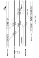
- FIG. 2 is a time chart illustrating an outline of an operation of synchronizing the broadcast stream and the communication stream by adjusting the STC in the receiving apparatus 300 according to the first embodiment of the present technology.
- the receiving apparatus 300 compares the time codes acquired from the broadcast stream and the communication stream at the time when the communication stream is first received after an instruction for synchronous reproduction of the broadcast stream and the communication stream is generated.
- the time code acquired from the broadcast stream is referred to as “first time code”
- the time code acquired from the communication stream is referred to as “second time code”.
- the first time code of the broadcast stream at the time when the communication stream is first received after the instruction of synchronous reproduction is generated is “TCb0”
- the communication stream received first after the instruction of synchronous reproduction It is determined whether the condition of TCb0> TCi00 is satisfied with the second time code of “TCi00”.
- the time code is originally expressed by four values (TCh, TCm, TCs, TCf) of hour, minute, second, and frame, but the above-mentioned TCb0 or TCi00 has the following four values. Assume that the value is converted to one value in millisecond units.
- TC (TCh ⁇ 60 + TCm) ⁇ 60 + TCs) ⁇ 1000 + TCf ⁇ 1000/60
- receiving apparatus 300 calculates offset ⁇ between “TCb0” and “TCi00” by the following equation.
- TCb0-TCi00 ⁇ (1)
- the receiving apparatus 300 adjusts the STC by the following equation with this offset ⁇ .
- STC ⁇ ⁇ 90 ⁇ m STC ′ (2)
- the reason why the offset ⁇ is multiplied by 90 is to map the offset ⁇ in milliseconds to the counter value of 90 KHz which is the same as STC.
- m is a predetermined margin.
- the receiving device 300 decodes the decoding target when the PTS included in the TS packet of the video of the broadcast stream coincides with the adjusted STC ′ at the time when the communication stream is first received.
- the video data of the communication stream having the second time code (TCi0) having the same value as the first time code (TCb0) is decoded. Thereafter, the synchronized playback of the broadcast stream and the communication stream is repeated in the same manner.
- the broadcast stream and the communication stream can be reproduced in synchronization.
- FIG. 3 is a diagram for explaining the time code of the MPEG2 video stream.
- Sequence_Header is described at the beginning of the picture layer which is the highest layer.
- Sequence_Header defines header data of a sequence of the MPEG2 bit stream.
- GOP_Header and Picture_Header are described after Sequence_Header.
- GOP_Header defines header data of the GOP (group_of_picture) layer of the MPEG bit stream. This GOP_Header is composed of group_start_code, time_code, closed_gop, broken_link, and the like.
- group_start_code is data indicating the start synchronization code of the GOP layer.
- time_code is a time code indicating the time from the start of the sequence of the first picture of the GOP. That is, time_code is a time code added for each GOP (first unit).
- closed_gop is flag data indicating that an image in a GOP can be reproduced independently from other GOPs.
- the broken_link is flag data indicating that the first B picture in the GOP cannot be accurately reproduced for editing or the like.
- the time_code is composed of data such as hour (hour), minute (minute), second (second), and frame (picture) indicating the presentation time of the first picture of the GOP.
- FIG. 4 is a diagram showing the configuration of the head access unit of the GOP of an MPEG4-AVC (Advanced Video Coding) video stream.
- the AU delimiter is information indicating a picture boundary position.
- SPS Sequence Parameter Set
- PPS Picture Parameter Set
- SEI Supplemental Enhancement Information
- Slice is data of one picture included in the access unit.
- Picture timing SEI includes Picture timing SEI.
- Picture timing SEI is timing information indicating the decoding and display timing of Slice (picture data).
- FIG. 5 is a diagram showing the configuration of an access unit other than the head of the GOP of the MPEG4-AVC video stream.
- Access units other than the head of the GOP include AU delimiter, PPS, SEI, and Slice.
- the SEI includes Picture timing SEI as in the top access unit of the GOP.
- Fig. 6 is a diagram showing the structure of Picture Timing SEI.
- Picture Timing SEI describes data of hour, minute, second and frame (n_frame). Therefore, in the MPEG4-AVC video stream, Picture Timing SEI is a time code indicating the presentation time for each picture. In other words, Picture Timing SEI is a time code added at least for each GOP.
- the MPEG2 video stream is used for video transmission by broadcasting
- the MPEG4-AVC video stream is used for video transmission by the Internet (communication). Therefore, in this case, time_code of the MPEG2 video stream is adopted as the first time code, and Picture timing SEI of the MPEG4-AVC video stream is adopted as the second time code.
- FIG. 7 is a block diagram illustrating a configuration of the receiving device 300 according to the present embodiment.
- the receiving apparatus 300 includes a tuner 301 (broadcast receiving unit), a broadcast DeMUX 302, a broadcast video buffer 303, a broadcast video decoder 304 (first video decoder), an STC generation unit 305 (reference time generation unit), Network I / F 307 (communication receiver), HTML browser 308, VOD player 309, communication streaming buffer 310, communication DeMUX 311, communication video buffer 312, STC adjustment unit 313 (adjustment unit), communication video A decoder 314 (second video decoder), a video merger 315, and a time code processing unit 316 are provided.
- the tuner 301 receives the broadcast stream (first video stream) of the channel selected by the user, generates a transport stream (TS: Transport Stream), and sends it to the broadcast DeMUX 302.
- TS Transport Stream
- the broadcast DeMUX 302 performs DeMUX processing of the transport stream, separates the video TS packets, supplies the video TS packets to the broadcast video buffer 303, and extracts the PCR from the video TS packets to generate the STC generation unit. 305 is supplied.
- the broadcast video buffer 303 buffers the video stream supplied to the broadcast video decoder 304.
- the broadcast video decoder 304 decodes the video stream read from the broadcast video buffer 303 using the STC of the STC generation unit 305 as a time base, and outputs a video signal to the video merger 315. More specifically, the broadcast video decoder 304 starts and outputs the decoding so that the video is presented at a timing when the PTS (Presentation Time Stamp) added to the video TS packet matches the STC value. Control the timing. Also, the broadcast video decoder 304 steadily supplies the time code (first time code) added to the video stream to be decoded to the time code processing unit 316 for the purpose of synchronous reproduction of broadcast and communication. .
- PTS Presentation Time Stamp
- the STC generation unit 305 generates a 27 megahertz STC based on the PCR extracted from the broadcast stream, and supplies it to the video decoder 304 for broadcasting.
- the STC generation unit 305 can adjust the STC based on the STC adjustment data from the STC adjustment unit 313.
- the network I / F 307 is a VOD player when a broadcast-linked application operating on an HTML (HyperText Markup Language) browser 308 issues an instruction for synchronous playback of a broadcast stream and a communication stream to a VOD (Video On Demand) player 309.
- the communication stream acquisition request given from 309 is transmitted to the distribution server of the broadcasting / communication facility 100 through the Internet, and the communication stream (second video) to be reproduced in synchronization with the broadcast stream as a response from the distribution server Stream).
- the communication streaming buffer 310 buffers the received communication stream.
- the communication streaming buffer 310 extracts the held communication stream and supplies it to the communication DeMUX 311.
- the communication DeMUX 311 separates the video TS packet from the communication stream extracted from the streaming buffer 310 and supplies the video TS packet to the communication video buffer 312 as a video stream.
- the communication video buffer 312 buffers the video stream supplied to the communication video decoder 314.
- the communication video decoder 314 decodes the video stream extracted from the communication video buffer 312 and supplies a communication video signal to the video merger 315. Further, the communication video decoder 314 adjusts the time code (second time code) included in the video data first acquired from the generation of the instruction for synchronous playback of the broadcast stream and the communication stream for the purpose of adjusting the STC.
- the code processing unit 316 is supplied. Further, after adjusting the STC, the video decoder for communication 314 uses the video data unit of the communication stream having the second time code having the same value as the first time code supplied from the time code processing unit 316 for communication.
- the video data is extracted from the video buffer 312, decoded, and output to the video merger 315 as a communication video signal.
- the video merger 315 merges the broadcast video signal and the communication video signal to generate a video signal for presentation, and outputs it to a display (not shown).
- the merging is performed by a method corresponding to a method for separating the program material into broadcasting and communication, such as a 3D program, a multi-view program, a high-resolution program, and an audio dubbing service program.
- the time code processing unit 316 first receives the second time code supplied from the communication video decoder 314 and the latest supplied from the broadcast video decoder 304 from the generation of an instruction for synchronous playback of the broadcast stream and the communication stream. Are compared with the first time code, and if the second time code is behind the first time code, the difference is supplied to the STC adjustment unit 313. After adjusting the STC, the time code processing unit 316 supplies the first time code supplied from the broadcast video decoder 304 to the communication video decoder 314 for the purpose of synchronous playback of the broadcast stream and the communication stream.
- the host controller 317 includes a CPU (Central Processing Unit), a ROM (Read Only Memory), a RAM (Random Access Memory), and the like. A program and data to be executed by the CPU are fixedly stored in the ROM.
- the RAM stores a program stored in the ROM, and the CPU executes the loaded program.
- the program loaded in the RAM causes the host controller 317 to operate as at least the STC generation unit 305, the HTML browser 308, the VOD player 309, the time code processing unit 316, and the STC adjustment unit 313.
- the host controller 317 can receive various instructions and data input from a user using a remote controller (not shown).
- the STC generation unit 305, the time code processing unit 316, and the STC adjustment unit 313 are not limited to being configured by software, and may be configured as hardware.
- the user of the receiving apparatus 300 selects a broadcast channel using a remote controller (not shown).
- the channel selection information from the user received by the remote controller or the like is processed by the host controller 317.
- the host controller 317 controls the tuner 301 based on channel selection information from the user.
- the broadcast stream of the channel received by the tuner 301 is sent to the broadcast DeMUX 302.
- the DeMUX 302 separates other TS packets such as video TS packets, audio TS packets, and SI (Service Information) from the broadcast stream.
- the video TS packet separated by the broadcast DeMUX 302 is supplied to the broadcast video buffer 303 as a video stream, and is temporarily held here.
- the broadcast DeMUX 302 regularly extracts the PCR from the video TS packet and supplies it to the STC generation unit 305.
- the STC generator 305 generates a 27 MHz STC (System Time Clock) based on this PCR.
- the broadcast video decoder 304 decodes the video stream read from the broadcast video buffer 303 and supplies the video signal to the video merger 315. At this time, the broadcast video decoder 304 displays the video stream in such a manner that the video is presented in a timing in which the PTS (Program Clock Reference) included in the video TS packet matches the STC provided from the STC generation unit 305. Control decode and output timing.
- the broadcast video decoder 304 supplies the time code added to the video stream to be decoded to the time code processing unit 316 for the purpose of synchronous playback of the broadcast stream and the communication stream.
- the receiving apparatus 300 acquires and executes an application (broadcast-linked application) associated with this channel or program through broadcasting or communication.
- This broadcast-linked application prompts the user to view, for example, a 3D program, a multi-view program, a high-resolution program, an audio dubbing service program, and the like by synchronized playback of a broadcast stream and a communication stream, and gives a viewing instruction (
- the reception apparatus 300 is caused to function so that the VOD player 309 transmits a communication stream acquisition request to the distribution server.
- this broadcast-linked application includes, for example, HTML (Hyper Text Markup Language) documents, BML documents (Broadcast Markup Language), MHEG documents (Multimedia and Hypermedia information coding), Java (registered trademark) scripts, still image files, and video files.
- HTML Hyper Text Markup Language
- BML documents Broadcast Markup Language
- MHEG documents Multimedia and Hypermedia information coding
- Java registered trademark
- the VOD player 309 When the VOD player 309 receives an instruction to synchronize playback of the broadcast stream and the communication stream, the VOD player 309 controls the network I / F 307 to transmit the communication stream (broadcast stream) associated with the channel or program being selected to the distribution server via the Internet. Request for transmission of a communication stream to be reproduced in synchronization with the time code, and gives an instruction to generate an offset ⁇ to the time code processing unit 316. When receiving this instruction, the time code processing unit 316 waits for the supply of the first time code from the video decoder 314 for communication.
- the communication stream transmitted from the distribution server in response to the request is accumulated in the communication streaming buffer 310 via the network I / F 307.
- the communication streaming buffer 310 holds the TS packet of the first video of the communication stream and immediately reads it and supplies it to the communication DeMUX 311.
- the communication DeMUX 311 separates the video TS packet from the communication stream read from the streaming buffer 310 and supplies it to the communication video buffer 312.
- the communication video decoder 314 decodes the video stream read from the communication video buffer 312 and supplies the video signal to the video merger 315. At this time, the communication video decoder 314 sends the second time code included in the video stream to the time code processing unit 316 as the first second time code from the generation of the instruction for synchronous playback of the broadcast stream and the communication stream. Supply.
- the first second time code supplied from the communication video decoder 314 is TCi00
- the first time code supplied from the broadcast video decoder 304 at the same timing as the second time code is TCb0.
- the time code processing unit 316 compares TCi00 and TCb0 and determines whether the condition of TCb0> TCi00 is satisfied.
- TCb0> TCi00 is established means that the video data of the communication stream to be reproduced in synchronization with the video data of the broadcast stream is actually received with a time delay. .
- the time code processing unit 316 calculates an offset ⁇ between TCb0 and TCi00 by the following equation.
- TCb0-TCi00 ⁇ (1)
- the value of the offset ⁇ is supplied to the STC adjustment unit 313.
- ⁇ ((TCbh ⁇ 60 + TCbm) ⁇ 60 + TCbs) ⁇ 1000 + TCbf ⁇ 1000/60 -((TCih x 60 + TCim) x 60 + TCis) x 1000 + TCif x 1000/60
- TCbh is a time code for broadcasting
- TCbm is a time code for broadcasting
- TCbs is a time code for broadcasting seconds
- TCbf is a time code for broadcasting frames.
- TCih is a time code for broadcasting
- TCim is a time code for minutes of communication
- TCis is a time code for communication seconds
- TCif is a time code for communication frames.
- the STC adjustment unit 313 Upon receiving the offset ⁇ , the STC adjustment unit 313 generates an STC adjustment value STC ′ according to the following equation.
- STC ⁇ ⁇ 90 ⁇ m STC ′ (2)
- the reason why the offset ⁇ is multiplied by 90 is to map the offset ⁇ in milliseconds to the counter value of 90 KHz which is the same as STC.
- m is a predetermined margin.
- the STC ′ generated as described above is supplied to the STC generation unit 305, and the STC generation unit 305 is reset by this STC ′, thereby completing the STC adjustment.
- the broadcast video decoder 304 extracts the first time code added to the video stream to be decoded and supplies the first time code to the time code processing unit 316, and also decodes the video stream and supplies the video signal to the video merger 315. To do.
- the receiving device 300 resumes the decoding and reproduction of the broadcast stream when the PTS included in the TS packet of the video of the broadcast stream matches STC ′.
- the communication video decoder 314 uses the video data unit of the video stream having the second time code (TCi0) having the same value as the first time code (TCb0) acquired from the time code processing unit 316 for communication. Are extracted from the video buffer 312 and decoded.
- the video signal obtained by the communication video decoder 314 is supplied to the video merger 315.
- the broadcast video signal and the communication video signal synchronized with each other are supplied to the video merger 315.
- the video merger 315 By supplying the video merger 315 with the broadcast video signal and the communication video signal synchronized with each other, the original 3D program, multi-view program, high-resolution program, audio dubbing service program, and the like are correctly restored.
- the adjusted STC ′ is returned to the original STC at the same time as the end of the broadcast program decoded by the STC ′.
- FIG. 8 is a time chart from the selection of the broadcast described above to the synchronization process between the broadcast stream and the communication stream, and further to the end of the synchronization process.
- the decoding start time of the video stream is shifted backward from T1 to T1 ′.
- the video is displayed in a frozen state from T1 to T1 ′.
- decoding of the video streams for broadcasting and communication is restarted at the same time from T1 ′.
- decoding is performed based on STC ′ until the program ends.
- STC ′ is returned to the STC, and the PTS jumps to the access unit that matches the STC to perform decoding.
- the broadcast video decoder 304 steadily supplies the first time code added to the video stream to be decoded to the time code processing unit 316.
- the time code processing unit 316 supplies the first time code supplied from the broadcast video decoder 304 to the communication video decoder 314 for the purpose of synchronous playback of the broadcast stream and the communication stream.
- the communication video decoder 314 extracts the video data unit of the communication stream having the second time code having the same value as the first time code supplied from the time code processing unit 316 from the communication video buffer 312. I decided to decode it.
- the video decoder for broadcasting and the video decoder for communication adjust the PTS (Presentation Time Stamp) added to each video TS packet.
- the decoding start and output timings may be controlled so that the video is presented at a timing that matches the later STC ′.
- FIG. 9 is a block diagram illustrating a configuration of a receiving device 300A according to the second embodiment.
- the time code processing unit 316 first receives the second time supplied from the video decoder for communication 314A from the generation of the instruction for synchronous playback of the broadcast stream and the communication stream. The code is compared with the latest first time code supplied from the broadcast video decoder 304A. When the second time code is delayed from the first time code, the time code processing unit 316 supplies the offset ⁇ to the STC adjustment unit 313.
- the STC adjustment unit 313 When receiving the offset ⁇ , the STC adjustment unit 313 generates an STC adjustment value STC ′, and gives the adjustment value STC ′ to the STC generation unit 305 to adjust the STC of the STC generation unit 305.
- the broadcast video decoder 304A is presented with the timing at which the PTS (Presentation Time Stamp) added to the TS packet of the broadcast stream video matches the adjusted STC ′ value.
- the decoding start and output timing are controlled.
- the video decoder for communication 314A similarly starts decoding and outputs so that the video is presented at a timing in which the PTS added to the TS packet of the video of the communication stream matches the adjusted STC ′ value. Control the timing.
- each stream can be reproduced with good synchronization.
- the STC is adjusted once before the start of the synchronized playback of the broadcast stream and the communication stream.
- the STC may be adjusted after the start of the synchronized playback.
- the STC adjustment after the start of the synchronous playback as described above is a synchronous transmission in which the program playback itself breaks down without the video of both the broadcast stream and the communication stream, particularly as in the 3D video Useful in the system.
- the margin m used when calculating the offset ⁇ may be variable according to the reception status of the communication stream. That is, if the margin is too large, the freeze time for displaying the broadcast stream becomes long, and the possibility of giving the viewer a sense of discomfort increases. On the other hand, if it is too short, there is a high possibility that playback of a 3D program or the like fails due to a lack of a communication stream. Therefore, it is desirable that the minimum necessary margin is dynamically set according to the reception status of the communication stream so that the program reproduction does not fail.
- the MPEG2 video stream is used for video transmission by broadcasting
- the MPEG4-AVC video stream is used for video transmission by the Internet (communication).
- the present technology is not limited to this.
- an MPEG2 video stream may be used for video transmission by broadcasting and communication
- an MPEG4-AVC video stream may be used for video transmission by broadcasting and communication.
- a video stream other than the MPEG2 video stream and the MPEG4-AVC video stream can be used as long as a time code is added for each predetermined unit of video data.
- this technique can also take the following structures.
- a broadcast receiving unit capable of receiving through broadcasting a first video stream to which a first time code is added for each first unit of first video data;
- a second video stream to which a second time code is added at least for each first unit of second video data to be reproduced in synchronization with the first video data can be received through a network.
- a reference time generation unit for generating a reference time for generating a timing of processing for presenting the first video data;
- the first time code added to the received first video stream and the second time code added to the second video stream are acquired at a predetermined timing, and the first time code is acquired.
- a time code processing unit for calculating a delay of the second time code with respect to the time code of An adjustment unit that adjusts the reference time in consideration of the delay.
- the receiving device is: A first video that is decoded so that the first video stream received by the broadcast receiving unit is presented at a timing when the presentation time information added to the first video stream matches the reference time.
- a decoder A second video decoder that decodes the second video stream received by the communication receiver;
- the time code processing unit obtains the first time code added to the first unit of the first video stream to be decoded by the first video decoder, and sends the first time code to the second video decoder.
- Supply The receiving device for decoding the first unit of the second video stream to which the second time code having the same value as the supplied first time code is added.
- the receiving apparatus adjusts the reference time with time data obtained by adding a predetermined margin to the delay.
- the receiving apparatus according to any one of (1) to (5), The first time code is added to the first picture of the GOP in the first video stream, and the second time code is added to each picture in the second video stream.
- Receiver device The first time code is added to the first picture of the GOP in the first video stream, and the second time code is added to each picture in the second video stream.
- the receiving device is: A first video that is decoded so that the first video stream received by the broadcast receiving unit is presented at a timing when the presentation time information added to the first video stream matches the reference time.
- a decoder A second video that is decoded so that the second video stream received by the communication receiver is presented at a timing when the presentation time information added to the second video stream matches the reference time.
- a decoder A receiving apparatus further comprising:
- the receiving device adjusts the reference time with time data obtained by adding a predetermined margin to the delay.
- the receiving device according to any one of (7) to (10), The first time code is added to the first picture of the GOP in the first video stream, and the second time code is added to each picture in the second video stream.
- Receiver device The first time code is added to the first picture of the GOP in the first video stream, and the second time code is added to each picture in the second video stream.
Abstract
Description
ことを特徴とする。 In the synchronization processing method according to another aspect of the present technology, the broadcast receiving unit receives the first video stream to which the first time code is added for each first unit of the first video data through broadcasting, A communication receiver receives a second video stream to which a second time code is added at least for each first unit of second video data to be reproduced in synchronization with the first video data. The time code processing unit receives the first time code added to the received first video stream and the second video stream added to the second video stream at a predetermined timing. 2 is obtained, the delay of the second time code with respect to the first time code is calculated, and the adjustment unit presents the first video stream in consideration of the delay. And adjusting the reference time for generating the timing of the process.
<第1の実施形態>
本実施形態は、放送により伝送される映像を含むストリーム(以下「放送ストリーム」と呼ぶ。)とインターネットにより伝送される映像を含むストリーム(以下「通信ストリーム」と呼ぶ。)を伝送する伝送装置と、伝送装置より伝送された放送ストリームと通信ストリームを受信し、これらを互いに同期させて再生する受信装置とその同期処理方法に関するものである。 Hereinafter, embodiments according to the present technology will be described.
<First Embodiment>
The present embodiment is a transmission apparatus that transmits a stream including video transmitted by broadcasting (hereinafter referred to as “broadcast stream”) and a stream including video transmitted via the Internet (hereinafter referred to as “communication stream”). The present invention relates to a receiving apparatus that receives a broadcast stream and a communication stream transmitted from a transmission apparatus and reproduces them in synchronization with each other and a synchronization processing method thereof.
1.3D番組
図1は3D番組伝送システムの構成を示す図である。
3D番組を構成する複数の視点の映像のうち1視点の映像が放送で伝送され、他の1視点の映像が通信で伝送される。受信機はこれら放送と通信で伝送される2つの映像を受信し、互いに同期をとって再生してマージし、3D映像を提示する。 The following is an example of such a synchronous transmission system for a broadcast stream and a communication stream.
1.3D Program FIG. 1 is a diagram showing a configuration of a 3D program transmission system.
One viewpoint video among a plurality of viewpoint videos constituting the 3D program is transmitted by broadcasting, and another one viewpoint video is transmitted by communication. The receiver receives these two images transmitted by broadcasting and communication, reproduces them in synchronization with each other, merges them, and presents a 3D image.
1つの被写体が複数のカメラで同時に撮影されることによって得られる一つのビューの映像がメインビューとして放送で伝送され、その他の1以上のビューの映像がサブビューとして通信で伝送される。受信機はこれら複数のビューの映像を受信し、メインビューの映像を親画面に表示させるとともに、1以上のサブビューの映像を子画面で表示させる。あるいは、受信機は、メイン画面に表示させる映像をメインビューとサブビューとの間で切り替える。 2. Multi-view program Video of one view obtained by simultaneously photographing a subject with a plurality of cameras is transmitted as a main view by broadcasting, and video of one or more other views are transmitted by communication as sub-views. The receiver receives the video of the plurality of views, displays the video of the main view on the main screen, and displays the video of one or more subviews on the sub screen. Alternatively, the receiver switches the video to be displayed on the main screen between the main view and the sub view.
例えば4Kの(画素数3840×2160)の高解像度カメラで撮影された映像が4分割されて得られる4系統のHDサイズ(画素数1920×1080)の映像のうち、一部が放送で伝送され、残りが通信で伝送される。受信機は各系統のHDサイズの映像を受信し、互いに同期をとって再生し、結合して4Kサイズの高解像度映像を提示する。あるいは、高解像度カメラで撮影された映像がウェーブレット変換などにより周波数分解され、低解像度成分のHDサイズの映像が放送で伝送され、残りの高周波成分の映像が通信で伝送される。受信機は、受信した4つのHDサイズの映像をウェーブレット逆変換などにより周波数合成して一つの高解像度映像として復元して提示する。 3. High-resolution programs For example, some of the 4 HD video (1920 × 1080 pixels) video that is obtained by dividing the video taken by a 4K (3840 × 2160) high-resolution camera into 4 broadcasts. The rest is transmitted by communication. The receiver receives HD video of each system, reproduces them in synchronization with each other, and combines them to present a high resolution video of 4K size. Alternatively, the video taken by the high-resolution camera is frequency-resolved by wavelet transform or the like, the HD video having a low resolution component is transmitted by broadcasting, and the video of the remaining high-frequency component is transmitted by communication. The receiver frequency-synthesizes the received four HD size images by inverse wavelet transform or the like, and restores and presents them as one high-resolution image.
音声吹き替えサービスでは、映像と日本語音声が放送で伝送され、映像に対する多言語の吹き替え版の音声が通信で伝送される。受信機は、映像と日本語音声を放送から受信する一方で、映像に対する多言語の吹き替え版の音声を通信から受信し、ユーザからの要求に応じて、放送の映像と吹き替え音声を互いに同期をとって再生して提示する。 4). Audio dubbing service In the audio dubbing service, video and Japanese audio are transmitted by broadcasting, and multilingual dubbed audio for the video is transmitted by communication. The receiver receives video and Japanese audio from the broadcast, while receiving multilingual dubbed audio for the video from communication, and synchronizes the broadcast video and dubbed audio to each other in response to a request from the user. Take it back and present it.
ここで、番組素材とは、3D番組、マルチビュー番組、高解像度番組、音声吹き替えサービス番組などである。放送・通信設備100において、番組素材は放送用の信号と通信用の信号とに分けられる。放送用の信号と通信用の信号はそれぞれ、エンコーダによってMPEG2_TSなどのストリームに符号化される。符号化されたストリームには提示時刻情報であるタイムコードが挿入される。タイムコードが挿入された一方のストリームは放送で送出され、タイムコードが挿入された他方のストリームは配信サーバによってインターネットを通じて通信で配信される。また、符号化の際には、ビデオのTSパケットに一定周期で時刻参照値であるPCR(Program Clock Reference)が挿入される。あるいは、PCRを含むPCRパケットが一定周期で付加される。 FIG. 1 is a diagram showing a configuration of a synchronous transmission system for the broadcast stream and communication stream.
Here, the program material is a 3D program, a multi-view program, a high-resolution program, an audio dubbing service program, or the like. In the broadcast /
図2は本技術に係る第1の実施形態の受信装置300において、STCの調整により放送ストリームと通信ストリームとを同期させる動作の概要を示すタイムチャートである。 [Overview of operation]
FIG. 2 is a time chart illustrating an outline of an operation of synchronizing the broadcast stream and the communication stream by adjusting the STC in the receiving apparatus 300 according to the first embodiment of the present technology.
ここで、同期再生の指示が発生してから最初に通信ストリームを受信した時点における、放送ストリームの第1のタイムコードを"TCb0"、同期再生の指示が発生してから最初に受信した通信ストリームの第2のタイムコードを"TCi00"としてTCb0>TCi00の条件が成立するかどうかを判定する。
尚、ここでタイムコードは本来、時、分、秒、フレームの4値(TCh,TCm,TCs,TCf)で表現されるが、上記でTCb0とかTCi00と称しているのは4値から以下の式にてミリセカンド単位の1値に変換したものを想定する。
TC=(TCh×60+TCm)×60+TCs)×1000+TCf×1000/60 1. The receiving apparatus 300 compares the time codes acquired from the broadcast stream and the communication stream at the time when the communication stream is first received after an instruction for synchronous reproduction of the broadcast stream and the communication stream is generated. The time code acquired from the broadcast stream is referred to as “first time code”, and the time code acquired from the communication stream is referred to as “second time code”.
Here, the first time code of the broadcast stream at the time when the communication stream is first received after the instruction of synchronous reproduction is generated is “TCb0”, and the communication stream received first after the instruction of synchronous reproduction is generated It is determined whether the condition of TCb0> TCi00 is satisfied with the second time code of “TCi00”.
Here, the time code is originally expressed by four values (TCh, TCm, TCs, TCf) of hour, minute, second, and frame, but the above-mentioned TCb0 or TCi00 has the following four values. Assume that the value is converted to one value in millisecond units.
TC = (TCh × 60 + TCm) × 60 + TCs) × 1000 + TCf × 1000/60
TCb0-TCi00=Δ ・・・(1) 2. When the above condition is satisfied, receiving apparatus 300 calculates offset Δ between “TCb0” and “TCi00” by the following equation.
TCb0-TCi00 = Δ (1)
STC-Δ×90-m=STC´ ・・・(2)
ここでオフセットΔに90を掛けるのは、ミリ秒単位のオフセットΔをSTCと同じ90KHzのカウンタ値にマッピングするためである。mは例えば予め決められたマージンである。 3. The receiving apparatus 300 adjusts the STC by the following equation with this offset Δ.
STC−Δ × 90−m = STC ′ (2)
Here, the reason why the offset Δ is multiplied by 90 is to map the offset Δ in milliseconds to the counter value of 90 KHz which is the same as STC. For example, m is a predetermined margin.
次に、MPEG2(Moving Picture Experts Group phase 2)ビデオストリームにおけるタイムコードについて説明する。
図3はMPEG2ビデオストリームのタイムコードを説明する図である。
最上位層であるピクチャ層の最初には、Sequence_Headerが記述されている。Sequence_HeaderはMPEG2ビットストリームのシーケンスのヘッダデータを定義するものである。Sequence_Headerの後ろにはGOP_Header、Picture_Headerが記述されている。
GOP_Headerは、MPEGビットストリームのGOP(group_of_picture)層のヘッダデータを定義するものである。このGOP_Headerは、group_start_code、time_code、closed_gop、およびbroken_linkなどから構成される。 [Time code]
Next, the time code in the MPEG2 (Moving Picture Experts Group phase 2) video stream will be described.
FIG. 3 is a diagram for explaining the time code of the MPEG2 video stream.
Sequence_Header is described at the beginning of the picture layer which is the highest layer. Sequence_Header defines header data of a sequence of the MPEG2 bit stream. GOP_Header and Picture_Header are described after Sequence_Header.
GOP_Header defines header data of the GOP (group_of_picture) layer of the MPEG bit stream. This GOP_Header is composed of group_start_code, time_code, closed_gop, broken_link, and the like.
time_codeは、GOPの先頭ピクチャのシーケンス先頭からの時間を示すタイムコードである。すなわち、time_codeはGOP(第1の単位)毎に付加されるタイムコードである。
closed_gopは、GOP内の画像が他のGOPから独立再生可能なことを示すフラグデータである。
broken_linkは、編集などのためにGOP内の先頭のBピクチャが正確に再生できないことを示すフラグデータである。
そしてtime_codeは、GOPの先頭ピクチャの提示時刻を示す時(hour)、分(minute)、秒(second)、フレーム(picture)などのデータで構成される。 group_start_code is data indicating the start synchronization code of the GOP layer.
time_code is a time code indicating the time from the start of the sequence of the first picture of the GOP. That is, time_code is a time code added for each GOP (first unit).
closed_gop is flag data indicating that an image in a GOP can be reproduced independently from other GOPs.
The broken_link is flag data indicating that the first B picture in the GOP cannot be accurately reproduced for editing or the like.
The time_code is composed of data such as hour (hour), minute (minute), second (second), and frame (picture) indicating the presentation time of the first picture of the GOP.
AU delimiterは、ピクチャ境界位置を示す情報である。
SPS(Sequence Parameter Set)は、ビデオシーケンスに関するパラメータである。SPSは、具体的には、ピクチャ単位またはスライス単位の仮想バッファのバッファサイズやビットレート情報が含まれる。
PPS(Picture Parameter Set)は、当該ピクチャに関するパラメータである。
SEI(Supplemental Enhancement Information)は、デコードに関する補助的な情報を含む付加情報である。
Sliceは、アクセスユニットに含まれる1つのピクチャのデータである。 FIG. 4 is a diagram showing the configuration of the head access unit of the GOP of an MPEG4-AVC (Advanced Video Coding) video stream.
The AU delimiter is information indicating a picture boundary position.
SPS (Sequence Parameter Set) is a parameter relating to a video sequence. Specifically, the SPS includes the buffer size and bit rate information of the virtual buffer in units of pictures or slices.
PPS (Picture Parameter Set) is a parameter related to the picture.
SEI (Supplemental Enhancement Information) is additional information including auxiliary information related to decoding.
Slice is data of one picture included in the access unit.
GOPの先頭以外のアクセスユニットは、AU delimiter、PPS、SEI、Sliceを含む。そしてSEIには、GOPの先頭のアクセスユニットと同様にPicture timing SEIが含まれている。 FIG. 5 is a diagram showing the configuration of an access unit other than the head of the GOP of the MPEG4-AVC video stream.
Access units other than the head of the GOP include AU delimiter, PPS, SEI, and Slice. The SEI includes Picture timing SEI as in the top access unit of the GOP.
図7は、本実施形態の受信装置300の構成を示すブロック図である。
受信装置300は、チューナ301(放送受信部)、放送用のDeMUX302、放送用の映像バッファ303、放送用の映像デコーダ304(第1の映像デコーダ)、STC生成部305(基準時刻生成部)、ネットワークI/F307(通信受信部)、HTMLブラウザ308、VODプレーヤ309、通信用のストリーミングバッファ310、通信用のDeMUX311、通信用の映像バッファ312、STC調整部313(調整部)、通信用の映像デコーダ314(第2の映像デコーダ)、映像マージャ315およびタイムコード処理部316を備える。 [Receiver configuration]
FIG. 7 is a block diagram illustrating a configuration of the receiving device 300 according to the present embodiment.
The receiving apparatus 300 includes a tuner 301 (broadcast receiving unit), a
また、放送用の映像デコーダ304は、放送と通信の同期再生を目的に、デコード対象の映像ストリームに付加されたタイムコード(第1のタイムコード)をタイムコード処理部316に定常的に供給する。 The
Also, the
また、通信用の映像デコーダ314は、STCの調整を目的に、放送ストリームと通信ストリームの同期再生の指示の発生から最初に取得した映像データに含まれるタイムコード(第2のタイムコード)をタイムコード処理部316に供給する。
さらに、STCの調整以後、通信用の映像デコーダ314は、タイムコード処理部316より供給された第1のタイムコードと同じ値の第2のタイムコードをもつ通信ストリームの映像データ単位を通信用の映像バッファ312から取り出してデコードし、通信系の映像信号として映像マージャ315に出力する。 The
Further, the
Further, after adjusting the STC, the video decoder for
タイムコード処理部316は、STCの調整以後、放送ストリームと通信ストリームの同期再生を目的に、放送用の映像デコーダ304より供給された第1のタイムコードを通信用の映像デコーダ314に供給する。 The time
After adjusting the STC, the time
RAMにロードされたプログラムは、ホストコントローラ317を、少なくとも、STC生成部305、HTMLブラウザ308、VODプレーヤ309、タイムコード処理部316、STC調整部313として動作させる。ホストコントローラ317は、例えば、図示しないリモートコントローラを用いてユーザからの各種指示やデータの入力を受け付けることが可能である。なお、STC生成部305、タイムコード処理部316およびSTC調整部313はソフトウェアで構成されることに限定されるものではなく、ハードウェアとして構成されてもよい。 The
The program loaded in the RAM causes the
次に、受信装置300において、放送の選局から放送ストリームと通信ストリームとの同期再生までの動作を説明する。 [Broadcast stream and communication stream synchronization processing]
Next, in the receiving apparatus 300, an operation from broadcast channel selection to synchronous reproduction of a broadcast stream and a communication stream will be described.
TCb0-TCi00=Δ ・・・(1)
このオフセットΔの値はSTC調整部313に供給される。 When the condition of TCb0> TCi00 is satisfied, the time
TCb0-TCi00 = Δ (1)
The value of the offset Δ is supplied to the
Δ=((TCbh×60+TCbm)×60+TCbs)×1000+TCbf×1000/60
-((TCih×60+TCim)×60+TCis)×1000+TCif×1000/60
によりミリ秒単位のオフセットΔが得られる。
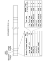
ここで、TCbhは放送の時単位のタイムコード、TCbmは放送の分単位のタイムコード、TCbsは放送の秒単位のタイムコード、TCbfは放送のフレーム単位のタイムコードである。TCihは放送の時単位のタイムコード、TCimは通信の分単位のタイムコード、TCisは通信の秒単位のタイムコード、TCifは通信のフレーム単位のタイムコードである。 Specifically, since the first time code and the second time code are expressed by a combination of hour, minute, second, and frame,
Δ = ((TCbh × 60 + TCbm) × 60 + TCbs) × 1000 + TCbf × 1000/60
-((TCih x 60 + TCim) x 60 + TCis) x 1000 + TCif x 1000/60
Gives an offset Δ in milliseconds.
Here, TCbh is a time code for broadcasting, TCbm is a time code for broadcasting, TCbs is a time code for broadcasting seconds, and TCbf is a time code for broadcasting frames. TCih is a time code for broadcasting, TCim is a time code for minutes of communication, TCis is a time code for communication seconds, and TCif is a time code for communication frames.
STC-Δ×90-m=STC´ ・・・(2)
ここで、オフセットΔに90を掛けるのは、ミリ秒単位のオフセットΔをSTCと同じ90KHzのカウンタ値にマッピングするためである。mは予め決められたマージンである。 Upon receiving the offset Δ, the
STC−Δ × 90−m = STC ′ (2)
Here, the reason why the offset Δ is multiplied by 90 is to map the offset Δ in milliseconds to the counter value of 90 KHz which is the same as STC. m is a predetermined margin.
受信装置300において、STCがSTC´に更新されることによって映像ストリームのデコードの開始時刻がT1からT1´に後方へとずらされる。T1からT1´までの間、映像はフリーズ状態で表示される。そしてT1´の時刻から放送と通信それぞれの映像ストリームのデコードが同時に再開される。その後、番組が終了するまで、STC´を基準にデコードが行われる。番組が終了すると、STC´がSTCに戻され、PTSがSTCに一致するアクセスユニットにジャンプしてデコードが行われる。 FIG. 8 is a time chart from the selection of the broadcast described above to the synchronization process between the broadcast stream and the communication stream, and further to the end of the synchronization process.
In the receiving apparatus 300, when the STC is updated to STC ′, the decoding start time of the video stream is shifted backward from T1 to T1 ′. The video is displayed in a frozen state from T1 to T1 ′. Then, decoding of the video streams for broadcasting and communication is restarted at the same time from T1 ′. Thereafter, decoding is performed based on STC ′ until the program ends. When the program ends, STC ′ is returned to the STC, and the PTS jumps to the access unit that matches the STC to perform decoding.
上記の第1の実施形態では、放送用の映像デコーダ304が、デコード対象の映像ストリームに付加された第1のタイムコードをタイムコード処理部316に定常的に供給する。タイムコード処理部316は、STCの調整以後、放送ストリームと通信ストリームの同期再生を目的に、放送用の映像デコーダ304より供給された第1のタイムコードを通信用の映像デコーダ314に供給する。そして通信用の映像デコーダ314は、タイムコード処理部316より供給された第1のタイムコードと同じ値の第2のタイムコードをもつ通信ストリームの映像データ単位を通信用の映像バッファ312から取り出してデコードすることとした。 <Second Embodiment>
In the first embodiment described above, the
この受信装置300Aにおいて、タイムコード処理部316は、第1の実施形態と同様、放送ストリームと通信ストリームの同期再生の指示の発生から最初に通信用の映像デコーダ314Aより供給された第2のタイムコードと、放送用の映像デコーダ304Aより供給された最新の第1のタイムコードとを比較する。タイムコード処理部316は、第2のタイムコードが第1のタイムコードよりも遅れている場合、そのオフセットΔをSTC調整部313に供給する。 FIG. 9 is a block diagram illustrating a configuration of a receiving device 300A according to the second embodiment.
In this receiving apparatus 300A, as in the first embodiment, the time
一方、通信用の映像デコーダ314Aも同様に、通信ストリームの映像のTSパケットに付加されたPTSが調整されたSTC´の値と一致するタイミンクでその映像が提示されるように、デコード開始および出力のタイミングを制御する。 After adjustment of the STC, the
On the other hand, the video decoder for
上記の第1の実施形態では、放送ストリームと通信ストリームとの同期再生の開始前に一度STCを調整するというものであるが、同期再生の開始以後もSTCの調整を行うようにしてよい。 <
In the first embodiment, the STC is adjusted once before the start of the synchronized playback of the broadcast stream and the communication stream. However, the STC may be adjusted after the start of the synchronized playback.
1.一定の時間周期(数分、数十分の周期)。
2.ストリーミングバッファ310に蓄えられた映像ストリームのサイズが一定値未満まで低下したとき。
3.通信用の映像バッファ312に蓄えられた映像ストリームのサイズが一定値未満まで低下したとき。
などが挙げられる。
但し、STCの調整は映像のフリーズ状態を誘発することから、あまり高い頻度で行うことは好ましくない。しかし、初回に一度のSTCの調整だけでは、インターネットの通信状況によっては、通信ストリームの受信が間に合わなくなる可能性がある。そこで、上記のように同期再生の開始以後もSTCの調整を行うことは、特に3D映像のように、放送ストリームと通信ストリームの両方の映像なしでは番組再生そのものが破綻してしまうような同期伝送システムにおいては有益である。 As a condition for adjusting the STC after the start of the synchronized playback, for example,
1. A certain period of time (a few minutes, a few tens of minutes).
2. When the size of the video stream stored in the
3. When the size of the video stream stored in the
Etc.
However, STC adjustment induces a video freeze state, so it is not preferable to perform STC adjustment too frequently. However, only by adjusting the STC once at the first time, reception of a communication stream may not be in time depending on the communication status of the Internet. Therefore, the STC adjustment after the start of the synchronous playback as described above is a synchronous transmission in which the program playback itself breaks down without the video of both the broadcast stream and the communication stream, particularly as in the 3D video Useful in the system.
(1) 第1の映像データの第1の単位毎に第1のタイムコードが付加された第1の映像ストリームを放送を通じて受信可能な放送受信部と、
前記第1の映像データに対して同期して再生されるべき第2の映像データの少なくとも前記第1の単位毎に第2のタイムコードが付加された第2の映像ストリームをネットワークを通じて受信可能な通信受信部と、
前記第1の映像データを提示する処理のタイミングを生成するための基準時刻を生成する基準時刻生成部と、
予め決められたタイミングで、前記受信された第1の映像ストリームに付加された前記第1のタイムコードと前記第2の映像ストリームに付加された前記第2のタイムコードを取得し、前記第1のタイムコードに対する前記第2のタイムコードの遅れ分を算出するタイムコード処理部と、
前記遅れ分を加味して前記基準時刻を調整する調整部と
を具備する受信装置。 In addition, this technique can also take the following structures.
(1) a broadcast receiving unit capable of receiving through broadcasting a first video stream to which a first time code is added for each first unit of first video data;
A second video stream to which a second time code is added at least for each first unit of second video data to be reproduced in synchronization with the first video data can be received through a network. A communication receiver;
A reference time generation unit for generating a reference time for generating a timing of processing for presenting the first video data;
The first time code added to the received first video stream and the second time code added to the second video stream are acquired at a predetermined timing, and the first time code is acquired. A time code processing unit for calculating a delay of the second time code with respect to the time code of
An adjustment unit that adjusts the reference time in consideration of the delay.
請求項1に記載の受信装置であって、
前記第1の映像ストリームには提示時刻情報が付加され、
前記受信装置は、
前記放送受信部により受信された前記第1の映像ストリームを、当該第1の映像ストリームに付加された前記提示時刻情報と前記基準時刻とが一致したタイミングで提示するようにデコードする第1の映像デコーダと、
前記通信受信部により受信された前記第2の映像ストリームをデコードする第2の映像デコーダと、をさらに具備し、
前記タイムコード処理部は、前記第1の映像デコーダによるデコード対象の前記第1の映像ストリームの前記第1の単位に付加された前記第1のタイムコードを取得して前記第2の映像デコーダに供給し、
前記第2の映像デコーダは、前記供給された前記第1のタイムコードと同じ値の前記第2のタイムコードが付加された前記第2の映像ストリームの前記第1の単位をデコードする
受信装置。 (2) The receiving device according to (1),
The receiving device according to
Presentation time information is added to the first video stream,
The receiving device is:
A first video that is decoded so that the first video stream received by the broadcast receiving unit is presented at a timing when the presentation time information added to the first video stream matches the reference time. A decoder;
A second video decoder that decodes the second video stream received by the communication receiver;
The time code processing unit obtains the first time code added to the first unit of the first video stream to be decoded by the first video decoder, and sends the first time code to the second video decoder. Supply
The receiving device for decoding the first unit of the second video stream to which the second time code having the same value as the supplied first time code is added.
前記調整部は、前記遅れ分に所定のマージンを付加した時間データで前記基準時刻を調整する
受信装置。 (3) The receiving apparatus according to any one of (1) to (2),
The receiver adjusts the reference time with time data obtained by adding a predetermined margin to the delay.
前記基準時刻生成部は、前記放送ストリームに付加された時刻参照値を用いて前記基準時刻を生成する
受信装置。 (4) The receiving device according to any one of (1) to (3),
The receiving apparatus that generates the reference time using a time reference value added to the broadcast stream.
前記基準時刻生成部は、前記放送ストリームに付加された時刻参照値を用いて前記基準時刻を生成する
受信装置。 (5) The receiving device according to any one of (1) to (4),
The receiving apparatus that generates the reference time using a time reference value added to the broadcast stream.
前記第1の映像ストリームには、GOPの先頭ピクチャに前記第1のタイムコードが付加され、前記第2の映像ストリームには、ピクチャ毎に前記第2のタイムコードが付加されたものである。
受信装置。 (6) The receiving apparatus according to any one of (1) to (5),
The first time code is added to the first picture of the GOP in the first video stream, and the second time code is added to each picture in the second video stream.
Receiver device.
前記第2の映像ストリームには提示時刻情報が付加され、
前記受信装置は、
前記放送受信部により受信された前記第1の映像ストリームを、当該第1の映像ストリームに付加された前記提示時刻情報と前記基準時刻とが一致したタイミングで提示するようにデコードする第1の映像デコーダと、
前記通信受信部により受信された前記第2の映像ストリームを、当該第2の映像ストリームに付加された前記提示時刻情報と前記基準時刻とが一致したタイミングで提示するようにデコードする第2の映像デコーダと、
をさらに具備する受信装置。 (7) The receiving device according to (1),
Presentation time information is added to the second video stream,
The receiving device is:
A first video that is decoded so that the first video stream received by the broadcast receiving unit is presented at a timing when the presentation time information added to the first video stream matches the reference time. A decoder;
A second video that is decoded so that the second video stream received by the communication receiver is presented at a timing when the presentation time information added to the second video stream matches the reference time. A decoder;
A receiving apparatus further comprising:
前記調整部は、前記遅れ分に所定のマージンを付加した時間データで前記基準時刻を調整する
受信装置。 (8) The receiving device according to (7),
The receiver adjusts the reference time with time data obtained by adding a predetermined margin to the delay.
前記基準時刻生成部は、前記放送ストリームに付加された時刻参照値を用いて前記基準時刻を生成する
受信装置。 (9) The receiving device according to any one of (7) to (8),
The receiving apparatus that generates the reference time using a time reference value added to the broadcast stream.
前記基準時刻生成部は、前記放送ストリームに付加された時刻参照値を用いて前記基準時刻を生成する
受信装置。 (10) The receiving device according to any one of (7) to (9),
The receiving apparatus that generates the reference time using a time reference value added to the broadcast stream.
前記第1の映像ストリームには、GOPの先頭ピクチャに前記第1のタイムコードが付加され、前記第2の映像ストリームには、ピクチャ毎に前記第2のタイムコードが付加されたものである。
受信装置。 (11) The receiving device according to any one of (7) to (10),
The first time code is added to the first picture of the GOP in the first video stream, and the second time code is added to each picture in the second video stream.
Receiver device.
300…受信装置
301…チューナ
302…放送用のDeMUX
303…放送用の映像バッファ
304…放送用の映像デコーダ
305…STC生成部
307…ネットワークI/F
308…HTMLブラウザ
309…VODプレーヤ
310…ストリーミングバッファ
311…通信用のDeMUX
312…通信用の映像バッファ
313…STC調整部
314…通信用の映像デコーダ
315…映像マージャ
316…タイムコード処理部
317…ホストコントローラ DESCRIPTION OF
303 ... Broadcasting
308 ...
312 ...
Claims (10)
- 第1の映像データの第1の単位毎に第1のタイムコードが付加された第1の映像ストリームを放送を通じて受信可能な放送受信部と、
前記第1の映像データに対して同期して再生されるべき第2の映像データの少なくとも前記第1の単位毎に第2のタイムコードが付加された第2の映像ストリームをネットワークを通じて受信可能な通信受信部と、
前記第1の映像データを提示する処理のタイミングを生成するための基準時刻を生成する基準時刻生成部と、
予め決められたタイミングで、前記受信された第1の映像ストリームに付加された前記第1のタイムコードと前記第2の映像ストリームに付加された前記第2のタイムコードを取得し、前記第1のタイムコードに対する前記第2のタイムコードの遅れ分を算出するタイムコード処理部と、
前記遅れ分を加味して前記基準時刻を調整する調整部と
を具備する受信装置。 A broadcast receiving unit capable of receiving, through broadcasting, a first video stream to which a first time code is added for each first unit of first video data;
A second video stream to which a second time code is added at least for each first unit of second video data to be reproduced in synchronization with the first video data can be received through a network. A communication receiver;
A reference time generation unit for generating a reference time for generating a timing of processing for presenting the first video data;
The first time code added to the received first video stream and the second time code added to the second video stream are acquired at a predetermined timing, and the first time code is acquired. A time code processing unit for calculating a delay of the second time code with respect to the time code of
An adjustment unit that adjusts the reference time in consideration of the delay. - 請求項1に記載の受信装置であって、
前記第1の映像ストリームには提示時刻情報が付加され、
前記受信装置は、
前記放送受信部により受信された前記第1の映像ストリームを、当該第1の映像ストリームに付加された前記提示時刻情報と前記基準時刻とが一致したタイミングで提示するようにデコードする第1の映像デコーダと、
前記通信受信部により受信された前記第2の映像ストリームをデコードする第2の映像デコーダと、をさらに具備し、
前記タイムコード処理部は、前記第1の映像デコーダによるデコード対象の前記第1の映像ストリームの前記第1の単位に付加された前記第1のタイムコードを取得して前記第2の映像デコーダに供給し、
前記第2の映像デコーダは、前記供給された前記第1のタイムコードと同じ値の前記第2のタイムコードが付加された前記第2の映像ストリームの前記第1の単位をデコードする
受信装置。 The receiving device according to claim 1,
Presentation time information is added to the first video stream,
The receiving device is:
A first video that is decoded so that the first video stream received by the broadcast receiving unit is presented at a timing when the presentation time information added to the first video stream matches the reference time. A decoder;
A second video decoder that decodes the second video stream received by the communication receiver;
The time code processing unit obtains the first time code added to the first unit of the first video stream to be decoded by the first video decoder, and sends the first time code to the second video decoder. Supply
The receiving device for decoding the first unit of the second video stream to which the second time code having the same value as the supplied first time code is added. - 請求項2に記載の受信装置であって、
前記タイムコード処理部は、少なくとも、前記放送ストリームの受信中に前記通信ストリームが最初に受信されたとき、前記受信された第1の映像ストリームに付加された前記第1のタイムコードと前記第2の映像ストリームに付加された前記第2のタイムコードを取得し、前記第1のタイムコードに対する前記第2のタイムコードの遅れ分を算出する
受信装置。 The receiving device according to claim 2,
The time code processing unit includes at least the first time code added to the received first video stream and the second time when the communication stream is first received during reception of the broadcast stream. A receiving device that obtains the second time code added to the video stream and calculates a delay of the second time code with respect to the first time code. - 請求項3に記載の受信装置であって、
前記調整部は、前記遅れ分に所定のマージンを付加した時間データで前記基準時刻を調整する
受信装置。 The receiving device according to claim 3,
The receiver adjusts the reference time with time data obtained by adding a predetermined margin to the delay. - 請求項4に記載の受信装置であって、
前記基準時刻生成部は、前記放送ストリームに付加された時刻参照値を用いて前記基準時刻を生成する
受信装置。 The receiving device according to claim 4,
The receiving apparatus that generates the reference time using a time reference value added to the broadcast stream. - 請求項5に記載の受信装置であって、
前記第1の映像ストリームには、GOPの先頭ピクチャに前記第1のタイムコードが付加され、
前記第2の映像ストリームには、ピクチャ毎に前記第2のタイムコードが付加されたものである
受信装置。 The receiving device according to claim 5,
In the first video stream, the first time code is added to the first picture of a GOP,
The receiving apparatus, wherein the second video stream is added with the second time code for each picture. - 請求項1に記載の受信装置であって、
前記第2の映像ストリームには提示時刻情報が付加され、
前記受信装置は、
前記放送受信部により受信された前記第1の映像ストリームを、当該第1の映像ストリームに付加された前記提示時刻情報と前記基準時刻とが一致したタイミングで提示するようにデコードする第1の映像デコーダと、
前記通信受信部により受信された前記第2の映像ストリームを、当該第2の映像ストリームに付加された前記提示時刻情報と前記基準時刻とが一致したタイミングで提示するようにデコードする第2の映像デコーダと、
をさらに具備する受信装置。 The receiving device according to claim 1,
Presentation time information is added to the second video stream,
The receiving device is:
A first video that is decoded so that the first video stream received by the broadcast receiving unit is presented at a timing when the presentation time information added to the first video stream matches the reference time. A decoder;
A second video that is decoded so that the second video stream received by the communication receiver is presented at a timing when the presentation time information added to the second video stream matches the reference time. A decoder;
A receiving apparatus further comprising: - 放送受信部が、第1の映像データの第1の単位毎に第1のタイムコードが付加された第1の映像ストリームを放送を通じて受信し、
通信受信部が、前記第1の映像データに対して同期して再生されるべき第2の映像データの少なくとも前記第1の単位毎に第2のタイムコードが付加された第2の映像ストリームをネットワークを通じて受信し、
タイムコード処理部が、予め決められたタイミングで、前記受信された第1の映像ストリームに付加された前記第1のタイムコードと前記第2の映像ストリームに付加された前記第2のタイムコードを取得し、前記第1のタイムコードに対する前記第2のタイムコードの遅れ分を算出し、
調整部が、前記遅れ分を加味して前記第1の映像ストリームを提示する処理のタイミングを生成するための基準時刻を調整する
同期処理方法。 The broadcast receiving unit receives the first video stream to which the first time code is added for each first unit of the first video data through broadcasting,
A communication receiver receives a second video stream to which a second time code is added at least for each first unit of second video data to be reproduced in synchronization with the first video data. Received through the network,
A time code processing unit that calculates the first time code added to the received first video stream and the second time code added to the second video stream at a predetermined timing; Obtaining and calculating a delay of the second time code with respect to the first time code;
The synchronization processing method, wherein the adjustment unit adjusts a reference time for generating the timing of the process of presenting the first video stream in consideration of the delay. - 請求項8に記載の同期処理方法であって、
前記基準時刻の調整後、前記タイムコード処理部が、第1の映像デコーダによるデコード対象の前記第1の映像ストリームの前記第1の単位に付加された前記第1のタイムコードを取得して第2の映像デコーダに供給し、
前記第2の映像デコーダが、前記供給された前記第1のタイムコードと同じ値の前記第2のタイムコードが付加された前記第2の映像ストリームの前記第1の単位をデコードする
同期処理方法。 The synchronization processing method according to claim 8, wherein
After the adjustment of the reference time, the time code processing unit obtains the first time code added to the first unit of the first video stream to be decoded by the first video decoder. 2 video decoder,
The second video decoder decodes the first unit of the second video stream to which the second time code having the same value as the supplied first time code is added. . - 請求項8に記載の同期処理方法であって、
前記基準時刻の調整後、第1の映像デコーダが、前記受信された前記第1の映像ストリームを、当該第1の映像ストリームに付加された前記提示時刻情報と前記基準時刻とが一致したタイミングで提示するようにデコードし、
前記基準時刻の調整後、第2の映像デコーダが、前記受信された前記第2の映像ストリームを、当該第2の映像ストリームに付加された前記提示時刻情報と前記基準時刻とが一致したタイミングで提示するようにデコードする
同期処理方法。 The synchronization processing method according to claim 8, wherein
After the adjustment of the reference time, the first video decoder determines that the received first video stream matches the presentation time information added to the first video stream and the reference time. Decode as presented,
After the adjustment of the reference time, the second video decoder determines that the received second video stream matches the presentation time information added to the second video stream and the reference time. Decoding as presented. Synchronous processing method.
Priority Applications (3)
| Application Number | Priority Date | Filing Date | Title |
|---|---|---|---|
| JP2014520906A JP6313704B2 (en) | 2012-06-22 | 2013-06-05 | Reception device and synchronization processing method thereof |
| EP13806945.5A EP2866457B1 (en) | 2012-06-22 | 2013-06-05 | Reception device, and synchronous processing method therefor |
| US14/400,612 US10397633B2 (en) | 2012-06-22 | 2013-06-05 | Receiver apparatus and synchronization processing method thereof |
Applications Claiming Priority (2)
| Application Number | Priority Date | Filing Date | Title |
|---|---|---|---|
| JP2012-140938 | 2012-06-22 | ||
| JP2012140938 | 2012-06-22 |
Publications (1)
| Publication Number | Publication Date |
|---|---|
| WO2013190789A1 true WO2013190789A1 (en) | 2013-12-27 |
Family
ID=49768404
Family Applications (1)
| Application Number | Title | Priority Date | Filing Date |
|---|---|---|---|
| PCT/JP2013/003527 WO2013190789A1 (en) | 2012-06-22 | 2013-06-05 | Reception device, and synchronous processing method therefor |
Country Status (5)
| Country | Link |
|---|---|
| US (1) | US10397633B2 (en) |
| EP (1) | EP2866457B1 (en) |
| JP (1) | JP6313704B2 (en) |
| AR (1) | AR091450A1 (en) |
| WO (1) | WO2013190789A1 (en) |
Cited By (7)
| Publication number | Priority date | Publication date | Assignee | Title |
|---|---|---|---|---|
| WO2015098376A1 (en) * | 2013-12-27 | 2015-07-02 | 日立マクセル株式会社 | Broadcast reception device and video display method |
| CN105516118A (en) * | 2015-12-03 | 2016-04-20 | Tcl集团股份有限公司 | Time synchronization method and time synchronization system based on non-RTC smart television |
| WO2017038481A1 (en) * | 2015-09-01 | 2017-03-09 | ソニー株式会社 | Receiving device, data processing method, and program |
| US20170208220A1 (en) * | 2016-01-14 | 2017-07-20 | Disney Enterprises, Inc. | Automatically synchronizing multiple real-time video sources |
| JP2018207505A (en) * | 2018-07-27 | 2018-12-27 | マクセル株式会社 | Broadcast reception device and video display method |
| JP2020188497A (en) * | 2019-03-26 | 2020-11-19 | ソニー株式会社 | Transmission method |
| JP2021166396A (en) * | 2020-07-29 | 2021-10-14 | ソニーグループ株式会社 | Transmission method |
Families Citing this family (6)
| Publication number | Priority date | Publication date | Assignee | Title |
|---|---|---|---|---|
| US8560719B2 (en) * | 2011-09-14 | 2013-10-15 | Mobitv, Inc. | Fragment server directed device fragment caching |
| US20150109413A1 (en) * | 2013-10-21 | 2015-04-23 | Electronics And Telecommunications Research Institute | Video reception apparatus to provide hybrid service based on transport stream system target decoder model |
| KR20150057149A (en) * | 2013-11-18 | 2015-05-28 | 한국전자통신연구원 | System and method for providing 3d broadcast service provision based on re-transmission broadcast networks |
| JP6127964B2 (en) * | 2013-12-26 | 2017-05-17 | ソニー株式会社 | Signal switching device and operation control method of signal switching device |
| US9344748B2 (en) * | 2014-03-31 | 2016-05-17 | Arris Enterprises, Inc. | Adaptive streaming transcoder synchronization |
| CN114598909B (en) * | 2022-03-30 | 2023-12-01 | 青岛海信宽带多媒体技术有限公司 | Intelligent set top box and time axis display method of live program |
Citations (4)
| Publication number | Priority date | Publication date | Assignee | Title |
|---|---|---|---|---|
| JP2005159592A (en) | 2003-11-25 | 2005-06-16 | Nippon Hoso Kyokai <Nhk> | Contents transmission apparatus and contents receiving apparatus |
| JP2008252831A (en) * | 2007-03-30 | 2008-10-16 | Sharp Corp | Broadcast receiver, broadcast retransmitting apparatus, broadcast retransmitting method, broadcast receiving system, control program, and computer readable recording medium with the control program recorded thereon |
| JP2011166615A (en) * | 2010-02-12 | 2011-08-25 | Nippon Telegr & Teleph Corp <Ntt> | Video synchronizing apparatus, video display device, video synchronizing method and program |
| JP2012010009A (en) * | 2010-06-23 | 2012-01-12 | Nippon Hoso Kyokai <Nhk> | Transmission device, server device, and reception device |
Family Cites Families (31)
| Publication number | Priority date | Publication date | Assignee | Title |
|---|---|---|---|---|
| JPH1032815A (en) * | 1996-07-16 | 1998-02-03 | Toshiba Corp | Image compositing device |
| US6587505B1 (en) * | 1998-08-31 | 2003-07-01 | Canon Kabushiki Kaisha | Image processing apparatus and method |
| US6512552B1 (en) * | 1999-03-29 | 2003-01-28 | Sony Corporation | Subpicture stream change control |
| EP1158799A1 (en) * | 2000-05-18 | 2001-11-28 | Deutsche Thomson-Brandt Gmbh | Method and receiver for providing subtitle data in several languages on demand |
| US7346698B2 (en) * | 2000-12-20 | 2008-03-18 | G. W. Hannaway & Associates | Webcasting method and system for time-based synchronization of multiple, independent media streams |
| JP4380930B2 (en) * | 2001-03-19 | 2009-12-09 | 株式会社東芝 | Audio / video decoding / playback apparatus and synchronized playback method thereof |
| US9948977B2 (en) * | 2003-01-09 | 2018-04-17 | Avago Technologies General Ip (Singapore) Pte. Ltd. | System, method, and apparatus for determining presentation time for picture without presentation time stamp |
| KR20060134911A (en) * | 2003-09-02 | 2006-12-28 | 소니 가부시끼 가이샤 | Content reception device, video/audio output timing control method, and content providing system |
| JP2005123789A (en) * | 2003-10-15 | 2005-05-12 | Matsushita Electric Ind Co Ltd | Av synchronization system |
| KR100526189B1 (en) * | 2004-02-14 | 2005-11-03 | 삼성전자주식회사 | Transcoding system and method for keeping timing parameters constant after transcoding |
| JP4229035B2 (en) * | 2004-09-28 | 2009-02-25 | ソニー株式会社 | Recording / reproducing apparatus and method, reproducing apparatus and method, recording apparatus and method, and program |
| US8140954B2 (en) * | 2005-06-05 | 2012-03-20 | International Business Machines Corporation | System and method for providing on demand captioning of broadcast programs |
| JP2007013714A (en) * | 2005-06-30 | 2007-01-18 | Toshiba Corp | Information playback apparatus and information playback method |
| CN100442858C (en) * | 2005-10-11 | 2008-12-10 | 华为技术有限公司 | Lip synchronous method for multimedia real-time transmission in packet network and apparatus thereof |
| JP2008005112A (en) * | 2006-06-21 | 2008-01-10 | Matsushita Electric Ind Co Ltd | Stream encoder and stream decoder |
| KR100905723B1 (en) * | 2006-12-08 | 2009-07-01 | 한국전자통신연구원 | System and Method for Digital Real Sense Transmitting/Receiving based on Non-Realtime |
| JP5212473B2 (en) * | 2008-06-26 | 2013-06-19 | 富士通セミコンダクター株式会社 | VIDEO / AUDIO DATA OUTPUT DEVICE AND VIDEO / AUDIO DATA OUTPUT METHOD |
| JP4409611B2 (en) * | 2008-08-04 | 2010-02-03 | シャープ株式会社 | Broadcast receiving apparatus, broadcast receiving method, control program, and computer-readable recording medium recording the control program |
| KR101535827B1 (en) * | 2008-12-05 | 2015-07-27 | 삼성전자주식회사 | Apparatus and method for audio and video synchronization in wireless communication network |
| KR101164857B1 (en) * | 2008-12-19 | 2012-07-11 | 한국전자통신연구원 | System and method for transmitting/receiving non-realtime stereoscopic broadcasting |
| JP2011066871A (en) * | 2009-08-21 | 2011-03-31 | Sony Corp | Content transmission method and display device |
| JP2011123195A (en) | 2009-12-09 | 2011-06-23 | Fuji Xerox Co Ltd | Fixing device and image forming apparatus |
| CA2845224A1 (en) * | 2010-04-04 | 2011-10-13 | Lg Electronics Inc. | Method and apparatus for processing non-real-time broadcast service and content transmitted by broadcast signal |
| KR20120010785A (en) * | 2010-07-27 | 2012-02-06 | 대양롤랜트 주식회사 | Multiple bearing unit with integrating a housing |
| KR101831775B1 (en) * | 2010-12-07 | 2018-02-26 | 삼성전자주식회사 | Transmitter and receiver for transmitting and receiving multimedia content, and reproducing method thereof |
| EP2498494A1 (en) * | 2011-03-11 | 2012-09-12 | Thomson Licensing | Decoder and method at the decoder for synchronizing the rendering of contents received through different networks |
| CN103621102B (en) * | 2011-05-12 | 2017-05-03 | 英特尔公司 | Method, device and system for synchronization of audio and video |
| WO2013021656A1 (en) * | 2011-08-11 | 2013-02-14 | パナソニック株式会社 | Playback device, playback method, integrated circuit, broadcasting system, and broadcasting method |
| JP5132808B1 (en) * | 2011-10-11 | 2013-01-30 | 株式会社東芝 | Digital broadcast recording / reproducing apparatus and digital broadcast recording / reproducing method |
| JP5121993B1 (en) * | 2011-10-11 | 2013-01-16 | 株式会社東芝 | Content processing apparatus and content synchronization method |
| JP5903924B2 (en) | 2012-02-17 | 2016-04-13 | ソニー株式会社 | Receiving apparatus and subtitle processing method |
-
2013
- 2013-06-05 WO PCT/JP2013/003527 patent/WO2013190789A1/en active Application Filing
- 2013-06-05 EP EP13806945.5A patent/EP2866457B1/en active Active
- 2013-06-05 US US14/400,612 patent/US10397633B2/en active Active
- 2013-06-05 JP JP2014520906A patent/JP6313704B2/en active Active
- 2013-06-14 AR ARP130102103 patent/AR091450A1/en unknown
Patent Citations (4)
| Publication number | Priority date | Publication date | Assignee | Title |
|---|---|---|---|---|
| JP2005159592A (en) | 2003-11-25 | 2005-06-16 | Nippon Hoso Kyokai <Nhk> | Contents transmission apparatus and contents receiving apparatus |
| JP2008252831A (en) * | 2007-03-30 | 2008-10-16 | Sharp Corp | Broadcast receiver, broadcast retransmitting apparatus, broadcast retransmitting method, broadcast receiving system, control program, and computer readable recording medium with the control program recorded thereon |
| JP2011166615A (en) * | 2010-02-12 | 2011-08-25 | Nippon Telegr & Teleph Corp <Ntt> | Video synchronizing apparatus, video display device, video synchronizing method and program |
| JP2012010009A (en) * | 2010-06-23 | 2012-01-12 | Nippon Hoso Kyokai <Nhk> | Transmission device, server device, and reception device |
Non-Patent Citations (2)
| Title |
|---|
| KINJI MATSUMURA ET AL.: "Hybridcast no Gaiyo to Gijutsu", NHK SCIENCE AND TECHNICAL RESEARCH LABORATORIES R&D REPORT, 15 November 2010 (2010-11-15), pages 10 - 17, XP008175577 * |
| KINJI MATSUMURA ET AL.: "Implementation Study of An Extra Content Service for Broadcast Programs using Synchronized IP Streaming", NEN THE INSTITUTE OF IMAGE INFORMATION AND TELEVISION ENGINEERS NENJI TAIKAI KOEN YOKOSHU, 2 August 2010 (2010-08-02), pages 10 - 5, XP008175584 * |
Cited By (19)
| Publication number | Priority date | Publication date | Assignee | Title |
|---|---|---|---|---|
| US10321186B2 (en) | 2013-12-27 | 2019-06-11 | Maxell, Ltd. | Broadcast reception device and video display method |
| WO2015098376A1 (en) * | 2013-12-27 | 2015-07-02 | 日立マクセル株式会社 | Broadcast reception device and video display method |
| EP3089465A4 (en) * | 2013-12-27 | 2017-07-05 | Hitachi Maxell, Ltd. | Broadcast reception device and video display method |
| JP2015126464A (en) * | 2013-12-27 | 2015-07-06 | 日立マクセル株式会社 | Broadcast receiver and video display method |
| US11716504B2 (en) | 2013-12-27 | 2023-08-01 | Maxell, Ltd. | Broadcast reception device and video display method |
| US11425455B2 (en) | 2013-12-27 | 2022-08-23 | Maxell, Ltd. | Broadcast reception device and video display method |
| US11134306B2 (en) | 2013-12-27 | 2021-09-28 | Maxell, Ltd. | Broadcast reception device and video display method |
| US10887644B2 (en) | 2015-09-01 | 2021-01-05 | Sony Corporation | Reception device, data processing method, and program |
| WO2017038481A1 (en) * | 2015-09-01 | 2017-03-09 | ソニー株式会社 | Receiving device, data processing method, and program |
| JPWO2017038481A1 (en) * | 2015-09-01 | 2018-06-21 | ソニー株式会社 | Reception device, data processing method, and program |
| CN105516118B (en) * | 2015-12-03 | 2019-06-11 | Tcl集团股份有限公司 | A kind of method for synchronizing time and system based on non-RTC smart television |
| CN105516118A (en) * | 2015-12-03 | 2016-04-20 | Tcl集团股份有限公司 | Time synchronization method and time synchronization system based on non-RTC smart television |
| US20170208220A1 (en) * | 2016-01-14 | 2017-07-20 | Disney Enterprises, Inc. | Automatically synchronizing multiple real-time video sources |
| US10764473B2 (en) * | 2016-01-14 | 2020-09-01 | Disney Enterprises, Inc. | Automatically synchronizing multiple real-time video sources |
| JP2018207505A (en) * | 2018-07-27 | 2018-12-27 | マクセル株式会社 | Broadcast reception device and video display method |
| JP2020188497A (en) * | 2019-03-26 | 2020-11-19 | ソニー株式会社 | Transmission method |
| JP2021166396A (en) * | 2020-07-29 | 2021-10-14 | ソニーグループ株式会社 | Transmission method |
| JP7120399B2 (en) | 2020-07-29 | 2022-08-17 | ソニーグループ株式会社 | Sending method |
| JP7371734B2 (en) | 2020-07-29 | 2023-10-31 | ソニーグループ株式会社 | How to send |
Also Published As
| Publication number | Publication date |
|---|---|
| AR091450A1 (en) | 2015-02-04 |
| US20150135247A1 (en) | 2015-05-14 |
| JPWO2013190789A1 (en) | 2016-02-08 |
| EP2866457A4 (en) | 2015-11-04 |
| EP2866457B1 (en) | 2019-03-20 |
| JP6313704B2 (en) | 2018-04-18 |
| EP2866457A1 (en) | 2015-04-29 |
| US10397633B2 (en) | 2019-08-27 |
Similar Documents
| Publication | Publication Date | Title |
|---|---|---|
| JP6313704B2 (en) | Reception device and synchronization processing method thereof | |
| US11284142B2 (en) | Reception method, transmission method, reception device, and transmission device | |
| JP6333173B2 (en) | Receiving apparatus and receiving method | |
| JP5903924B2 (en) | Receiving apparatus and subtitle processing method | |
| CA2554306C (en) | Synchronization and automation in an itv environment | |
| US8189679B2 (en) | Content receiving apparatus, method of controlling video-audio output timing and content providing system | |
| US8760579B2 (en) | Video display apparatus, video display system and video display method | |
| KR20140022716A (en) | Image data transmitting device, image data transmitting method and image data receiving device | |
| KR20060134911A (en) | Content reception device, video/audio output timing control method, and content providing system | |
| EP2485501B1 (en) | Fast channel change companion stream solution with bandwidth optimization | |
| US20120173668A1 (en) | Content transmitting apparatus, content receiving apparatus, content transmission program, content reception program, content transmitting method, and content receiving method | |
| JP2004297628A (en) | Stream switching apparatus and apparatus for providing contents thereto | |
| US20150109411A1 (en) | Image playback apparatus for 3dtv and method performed by the apparatus | |
| US9426506B2 (en) | Apparatuses for providing and receiving augmented broadcasting service in hybrid broadcasting environment | |
| US8769562B2 (en) | Digital broadcast method, data receiving device, and data transmitting device | |
| EP2814256B1 (en) | Method and apparatus for modifying a stream of digital content | |
| JP2012169993A (en) | Content synchronization device, content synchronization method, and content synchronization program | |
| CN108702533B (en) | Transmission device, transmission method, reception device, and reception method | |
| KR100802133B1 (en) | Digital signal processing apparatus for synchronizing between video and audio, and method thereof | |
| CN114189737A (en) | Digital television and rapid channel switching method thereof | |
| JP2004007541A (en) | Data multiplexing method and multiplexed data decoding method | |
| JP2005198105A (en) | Synchronization signal generator |
Legal Events
| Date | Code | Title | Description |
|---|---|---|---|
| 121 | Ep: the epo has been informed by wipo that ep was designated in this application |
Ref document number: 13806945 Country of ref document: EP Kind code of ref document: A1 |
|
| WWE | Wipo information: entry into national phase |
Ref document number: 14400612 Country of ref document: US |
|
| ENP | Entry into the national phase |
Ref document number: 2014520906 Country of ref document: JP Kind code of ref document: A |
|
| WWE | Wipo information: entry into national phase |
Ref document number: 2013806945 Country of ref document: EP |
|
| NENP | Non-entry into the national phase |
Ref country code: DE |