WO2013187334A1 - Video encoding device, video decoding device, video encoding method, video decoding method, and program - Google Patents
Video encoding device, video decoding device, video encoding method, video decoding method, and program Download PDFInfo
- Publication number
- WO2013187334A1 WO2013187334A1 PCT/JP2013/065875 JP2013065875W WO2013187334A1 WO 2013187334 A1 WO2013187334 A1 WO 2013187334A1 JP 2013065875 W JP2013065875 W JP 2013065875W WO 2013187334 A1 WO2013187334 A1 WO 2013187334A1
- Authority
- WO
- WIPO (PCT)
- Prior art keywords
- video
- encoding
- decoding
- component
- unit
- Prior art date
Links
Images


Classifications
-
- H—ELECTRICITY
- H04—ELECTRIC COMMUNICATION TECHNIQUE
- H04N—PICTORIAL COMMUNICATION, e.g. TELEVISION
- H04N19/00—Methods or arrangements for coding, decoding, compressing or decompressing digital video signals
- H04N19/10—Methods or arrangements for coding, decoding, compressing or decompressing digital video signals using adaptive coding
- H04N19/102—Methods or arrangements for coding, decoding, compressing or decompressing digital video signals using adaptive coding characterised by the element, parameter or selection affected or controlled by the adaptive coding
- H04N19/103—Selection of coding mode or of prediction mode
- H04N19/105—Selection of the reference unit for prediction within a chosen coding or prediction mode, e.g. adaptive choice of position and number of pixels used for prediction
-
- H—ELECTRICITY
- H04—ELECTRIC COMMUNICATION TECHNIQUE
- H04N—PICTORIAL COMMUNICATION, e.g. TELEVISION
- H04N19/00—Methods or arrangements for coding, decoding, compressing or decompressing digital video signals
- H04N19/85—Methods or arrangements for coding, decoding, compressing or decompressing digital video signals using pre-processing or post-processing specially adapted for video compression
- H04N19/89—Methods or arrangements for coding, decoding, compressing or decompressing digital video signals using pre-processing or post-processing specially adapted for video compression involving methods or arrangements for detection of transmission errors at the decoder
- H04N19/895—Methods or arrangements for coding, decoding, compressing or decompressing digital video signals using pre-processing or post-processing specially adapted for video compression involving methods or arrangements for detection of transmission errors at the decoder in combination with error concealment
-
- H—ELECTRICITY
- H04—ELECTRIC COMMUNICATION TECHNIQUE
- H04N—PICTORIAL COMMUNICATION, e.g. TELEVISION
- H04N19/00—Methods or arrangements for coding, decoding, compressing or decompressing digital video signals
- H04N19/10—Methods or arrangements for coding, decoding, compressing or decompressing digital video signals using adaptive coding
- H04N19/169—Methods or arrangements for coding, decoding, compressing or decompressing digital video signals using adaptive coding characterised by the coding unit, i.e. the structural portion or semantic portion of the video signal being the object or the subject of the adaptive coding
- H04N19/186—Methods or arrangements for coding, decoding, compressing or decompressing digital video signals using adaptive coding characterised by the coding unit, i.e. the structural portion or semantic portion of the video signal being the object or the subject of the adaptive coding the unit being a colour or a chrominance component
-
- H—ELECTRICITY
- H04—ELECTRIC COMMUNICATION TECHNIQUE
- H04N—PICTORIAL COMMUNICATION, e.g. TELEVISION
- H04N19/00—Methods or arrangements for coding, decoding, compressing or decompressing digital video signals
- H04N19/10—Methods or arrangements for coding, decoding, compressing or decompressing digital video signals using adaptive coding
- H04N19/169—Methods or arrangements for coding, decoding, compressing or decompressing digital video signals using adaptive coding characterised by the coding unit, i.e. the structural portion or semantic portion of the video signal being the object or the subject of the adaptive coding
- H04N19/187—Methods or arrangements for coding, decoding, compressing or decompressing digital video signals using adaptive coding characterised by the coding unit, i.e. the structural portion or semantic portion of the video signal being the object or the subject of the adaptive coding the unit being a scalable video layer
-
- H—ELECTRICITY
- H04—ELECTRIC COMMUNICATION TECHNIQUE
- H04N—PICTORIAL COMMUNICATION, e.g. TELEVISION
- H04N19/00—Methods or arrangements for coding, decoding, compressing or decompressing digital video signals
- H04N19/30—Methods or arrangements for coding, decoding, compressing or decompressing digital video signals using hierarchical techniques, e.g. scalability
- H04N19/31—Methods or arrangements for coding, decoding, compressing or decompressing digital video signals using hierarchical techniques, e.g. scalability in the temporal domain
-
- H—ELECTRICITY
- H04—ELECTRIC COMMUNICATION TECHNIQUE
- H04N—PICTORIAL COMMUNICATION, e.g. TELEVISION
- H04N19/00—Methods or arrangements for coding, decoding, compressing or decompressing digital video signals
- H04N19/30—Methods or arrangements for coding, decoding, compressing or decompressing digital video signals using hierarchical techniques, e.g. scalability
- H04N19/33—Methods or arrangements for coding, decoding, compressing or decompressing digital video signals using hierarchical techniques, e.g. scalability in the spatial domain
-
- H—ELECTRICITY
- H04—ELECTRIC COMMUNICATION TECHNIQUE
- H04N—PICTORIAL COMMUNICATION, e.g. TELEVISION
- H04N19/00—Methods or arrangements for coding, decoding, compressing or decompressing digital video signals
- H04N19/50—Methods or arrangements for coding, decoding, compressing or decompressing digital video signals using predictive coding
- H04N19/503—Methods or arrangements for coding, decoding, compressing or decompressing digital video signals using predictive coding involving temporal prediction
Definitions
- the present invention relates to a video encoding device, a video decoding device, a video encoding method, a video decoding method, and a program.
- formats such as YUV and RGB have been defined for pixel value representation methods in video signals.
- Each format defines a sampling method for color components, and also defines a plurality of expression bit numbers for color components.
- the format, the sampling method, and the combination of the number of bits are collectively referred to as a video format.
- a video format it is possible to convert the videos to each other by thinning out pixel values, interpolation processing, or the like.
- the format is, for example, YUV, RGB, Lab, CMYK, or the like.
- the sampling method is 4: 4: 4, 4: 2: 2, or 4: 2: 0 for YUV, for example.
- the number of bits is the number of bits per pixel.
- the input / output video corresponds to a predetermined video format and can be used properly according to the application.
- a profile SVC profile
- resolution scalability is defined in this profile.
- JVT Joint Video Team
- ISO / IEC MPEG and ITU-T VCEG "Text of ISO / IEC 14496-10 Advanced Video Coding"
- the present invention has been made in view of the above-described problems, and an object thereof is to efficiently compress a plurality of videos having the same design but different video formats.
- the present invention proposes the following matters in order to solve the above problems.
- the present invention is a moving image coding apparatus capable of scalable coding of an input video, wherein the input video is converted into a video having a video format different from the video format of the input video, and after the conversion Using video format conversion means for generating video, encoding side prediction means for predicting information lost when the converted video is generated by the video format conversion means, and prediction results by the encoding side prediction means
- a first encoding unit that encodes the input video a second encoding unit that encodes the converted video generated by the video format conversion unit, and a first encoding unit.
- the encoded result and the encoded result by the second encoding means are multiplexed to generate compressed data having scalability related to the video format.
- a video encoding device characterized by comprising multiplexing means.
- a moving picture coding apparatus capable of scalable coding of an input video includes a video format conversion means, a coding side prediction means, a first coding means, a second coding means, and a multiplexing Means were provided.
- the video format conversion means converts the input video to a video having a video format different from the video format of the input video, and generates a converted video.
- the encoding side prediction means predicts information lost when the converted video is generated by the video format conversion means.
- the input video is encoded by the first encoding unit using the prediction result by the encoding side prediction unit.
- the converted video generated by the video format conversion means is encoded by the second encoding means.
- the multiplexing unit multiplexes the encoding result of the first encoding unit and the encoding result of the second encoding unit to generate compressed data having scalability related to the video format. .
- the video format conversion means uses the input video (for example, , Corresponding to the format of the input video a in FIG. 4) and having a video format with less color information than the input video (for example, corresponding to the lower layer video x in FIG. 4).
- a featured video encoding device has been proposed.
- the video format conversion means uses the video format conversion means to convert the video having the same format as the input video and having less color information than the input video. It was decided to generate. For this reason, the same effect as the effect mentioned above can be produced by performing the inter-layer prediction based on the inter-color component prediction using the correlation between the components described above.
- the present invention corresponds to the first encoding means (for example, the entropy encoding unit 15 in FIG. 2 and the entropy encoding unit 25 in FIG. 3) in the moving picture encoding apparatus of (2). ) Performs base layer encoding by an existing standard method, and the encoding side prediction means (e.g., corresponding to the prediction value generation unit 12 in FIG. 2) is a pixel value of the luminance component of the decoded image of the base layer. Has been proposed to predict the lost color information.
- the encoding side prediction means e.g., corresponding to the prediction value generation unit 12 in FIG. 2
- the first encoding unit performs base layer encoding by the existing standard method, and the encoding side prediction unit performs base layer decoding image.
- the lost color information is predicted using the pixel value of the luminance component. Therefore, inter-layer prediction based on inter-color component prediction is performed using the correlation between luminance and color information, and the same effects as described above can be achieved.
- the present invention relates to the moving image encoding apparatus according to (3), wherein the encoding side prediction means includes a pixel value of a luminance component of a decoded image for the input video and a decoded image for the converted video.
- the encoding side prediction means includes a pixel value of a luminance component of a decoded image for the input video and a decoded image for the converted video.
- a moving image encoding device is proposed.
- the encoding side prediction means causes the pixel value of the luminance component of the decoded image for the input video and the pixel of the luminance component of the decoded image for the converted video. Based on the polynomial approximation, a predicted value of the color difference component lost when the converted video is generated from the input video by the video format conversion means is generated. Therefore, inter-layer prediction based on inter-color component prediction is performed using the correlation between luminance and color information, and the same effects as described above can be achieved.
- the present invention relates to the moving image encoding apparatus according to (3), wherein the encoding side prediction means includes a pixel value of a luminance component of a decoded image for the input video and a decoded image for the converted video. And the pixel value of the luminance component, and based on an interpolation filter that minimizes the error of the processing pixel value, the color difference component lost when the converted video is generated from the input video by the video format conversion unit.
- a moving picture coding apparatus that generates a predicted value is proposed.
- the encoding side prediction means causes the pixel value of the luminance component of the decoded image for the input video and the pixel of the luminance component of the decoded image for the converted video. And generating a predicted value of the color difference component lost when the converted video is generated from the input video by the video format conversion means based on the interpolation filter that minimizes the error of the processing pixel value. did. Therefore, inter-layer prediction based on inter-color component prediction is performed using the correlation between luminance and color information, and the same effects as described above can be achieved.
- the present invention relates to the moving image encoding apparatus according to (3), wherein the encoding side prediction means includes a pixel value of a luminance component of a decoded image for the input video and a decoded image for the converted video.
- the encoding side prediction means includes a pixel value of a luminance component of a decoded image for the input video and a decoded image for the converted video.
- a video encoding device is proposed.
- the encoding side prediction means causes the pixel value of the luminance component of the decoded image for the input video and the pixel of the luminance component of the decoded image for the converted video. Based on the non-linear interpolation processing, the predicted value of the color difference component lost when the converted video is generated from the input video by the video format conversion means is generated. Therefore, inter-layer prediction based on inter-color component prediction is performed using the correlation between luminance and color information, and the same effects as described above can be achieved.
- the present invention relates to the video encoding device of (1), wherein the video format conversion means (for example, equivalent to the color format conversion unit 226 in FIG. 11) uses the input video (for example, the converted video as the converted video). And a video format (for example, equivalent to the converted video ⁇ in FIG. 11) having a format different from that of the input video ⁇ in FIG. 11 and having a smaller data amount per pixel than the input video.
- the video format conversion means for example, equivalent to the color format conversion unit 226 in FIG. 11
- the input video for example, the converted video as the converted video.
- a video format for example, equivalent to the converted video ⁇ in FIG. 11 having a format different from that of the input video ⁇ in FIG. 11 and having a smaller data amount per pixel than the input video.
- the video format conversion means uses a format different from the format of the input video as the post-conversion video, and the data amount per pixel is smaller than that of the input video. It was decided to generate video in video format. For this reason, it is possible to perform the inter-layer prediction based on the inter-color component prediction using the above-described correlation between the components, and achieve the same effect as the above-described effect.
- the first encoding unit (e.g., equivalent to the entropy encoding unit 216 in FIG. 10) is a base layer encoding according to an existing standard method.
- the encoding-side prediction unit (e.g., corresponding to the prediction value generation unit 213 in FIG. 10) uses one pixel value among a plurality of components constituting the base layer decoded image, and A moving picture coding apparatus is proposed which is characterized by predicting lost information.
- the first encoding unit performs base layer encoding by the existing standard method
- the encoding side prediction unit performs the base layer decoded image.
- the lost information is predicted by using one pixel value of a plurality of components constituting the.
- the inter-layer prediction based on the inter-color component prediction is performed by using a correlation between predetermined components such as the Y component in the YUV format and the G component in the RGB format, and the above-mentioned. The same effect as that obtained can be achieved.
- the present invention relates to the moving picture coding apparatus according to (8), wherein a specific component (for example, a G component in an RGB format described later) is one of a plurality of components constituting a decoded image of the input video. And a predetermined component (e.g., corresponding to a Y component in a YUV format described later) that is one of a plurality of components constituting a decoded image of the converted video, and
- the encoding side prediction means uses the pixel value of the specific component of the decoded image for the input video and the pixel value of the predetermined component of the decoded image for the converted video based on polynomial approximation, and Proposes a moving picture coding apparatus that generates predicted values of components lost when the converted video is generated from the input video by the video format conversion means.
- a specific component that is one of a plurality of components constituting a decoded image for an input video and a decoded image for a converted video are configured.
- a predetermined component which is one of a plurality of components is in a pair relationship.
- the encoding side prediction means uses the pixel value of the specific component of the decoded image for the input video and the pixel value of the predetermined component of the decoded image for the converted video to convert the video format based on polynomial approximation. The predicted value of the component lost when the converted video is generated from the input video by the means is generated.
- the inter-layer prediction based on the inter-color component prediction is performed by using a correlation between predetermined components such as the Y component in the YUV format and the G component in the RGB format, and the above-mentioned.
- predetermined components such as the Y component in the YUV format and the G component in the RGB format
- the present invention relates to the moving picture coding apparatus according to (8), wherein a specific component that is one of a plurality of components constituting a decoded image for the input video (for example, a G component in an RGB format described later) And a predetermined component (e.g., corresponding to a Y component in a YUV format described later) that is one of a plurality of components constituting a decoded image of the converted video, and
- the encoding-side prediction means uses the pixel value of the specific component of the decoded image for the input video and the pixel value of the predetermined component of the decoded image for the converted video to generate an error in the processing pixel value.
- the video format conversion unit Based on a minimum interpolation filter, the video format conversion unit generates a predicted value of a component lost when the converted video is generated from the input video. It proposes a moving picture coding apparatus.
- a specific component that is one of a plurality of components constituting a decoded image for an input video and a decoded image for a converted video are configured.
- a predetermined component which is one of a plurality of components is in a pair relationship.
- the encoding-side prediction means uses the pixel value of the specific component of the decoded image for the input video and the pixel value of the predetermined component of the decoded image for the converted video to minimize the error of the processing pixel value.
- the predicted value of the component lost when the converted video is generated from the input video by the video format conversion means is generated.
- the inter-layer prediction based on the inter-color component prediction is performed by using a correlation between predetermined components such as the Y component in the YUV format and the G component in the RGB format, and the above-mentioned.
- predetermined components such as the Y component in the YUV format and the G component in the RGB format
- the present invention relates to the moving picture coding apparatus according to (8), wherein a specific component (for example, a G component in an RGB format described later) is one of a plurality of components constituting a decoded image for the input video. And a predetermined component (e.g., corresponding to a Y component in a YUV format described later) that is one of a plurality of components constituting a decoded image of the converted video, and
- the encoding side prediction means uses the pixel value of the specific component of the decoded image for the input video and the pixel value of the predetermined component of the decoded image for the converted video, based on nonlinear interpolation processing, Proposed a moving picture coding apparatus for generating a prediction value of a component lost when the converted video is generated from the input video by the video format conversion means.
- a specific component that is one of a plurality of components constituting a decoded image for an input video and a decoded image for a converted video are configured.
- a predetermined component which is one of a plurality of components is in a pair relationship.
- the encoding side prediction means uses the pixel value of the specific component of the decoded image for the input video and the pixel value of the predetermined component of the decoded image for the converted video based on the non-linear interpolation process to generate a video format. The predicted value of the component lost when the converted image is generated from the input image by the conversion means is generated.
- the inter-layer prediction based on the inter-color component prediction is performed by using a correlation between predetermined components such as the Y component in the YUV format and the G component in the RGB format, and the above-mentioned.
- predetermined components such as the Y component in the YUV format and the G component in the RGB format
- the present invention provides a moving picture decoding capable of scalable decoding with respect to compressed data (for example, equivalent to the compressed stream b in FIG. 5) generated by the moving picture encoding apparatus according to any one of (1) to (6).
- a demultiplexing unit that extracts a video encoding result for each video format from the compressed data; a decoding unit that decodes the encoding result for each video format extracted by the demultiplexing unit; Decoding side prediction means for predicting information lost when the converted video is generated from the input video by the video format conversion means, video decoded by the decoding means, and prediction result by the decoding side prediction means And a first video output means for obtaining the input video and a second for obtaining the converted video based on the video decoded by the decoding means. It proposes a video decoding apparatus characterized by comprising, a video output unit.
- a demultiplexing unit, a decoding unit, and a decoding side are provided in a moving image decoding apparatus capable of scalable decoding of compressed data generated by any one of the moving image encoding apparatuses of (1) to (6).
- Prediction means, first video output means, and second video output means are provided.
- the video encoding result is extracted for each video format from the compressed data by the demultiplexing means.
- the decoding unit decodes the encoding result for each video format extracted by the demultiplexing unit.
- the decoding side prediction means predicts information lost when the converted video is generated from the input video by the video format conversion means.
- the first video output unit obtains the input video by using the video decoded by the decoding unit and the prediction result by the decoding side prediction unit.
- the second video output means obtains the converted video based on the video decoded by the decoding means.
- the present invention corresponds to the decoding means (for example, the entropy decoding unit 111 in FIG. 6, the entropy decoding unit 121 in FIG. 7, and the entropy decoding unit 131 in FIG. 8) in the moving picture decoding apparatus in (12).
- the decoding means for example, the entropy decoding unit 111 in FIG. 6, the entropy decoding unit 121 in FIG. 7, and the entropy decoding unit 131 in FIG. 8 in the moving picture decoding apparatus in (12).
- the decoding result of the enhancement layer different from the base layer is decoded, and the decoding side prediction means (e.g., corresponding to the predicted value generation unit 114 in FIG. 6) is a pixel of the luminance component of the decoded image of the base layer
- the decoding unit decodes the base layer encoding result encoded by the existing standard method, and the encoding result extracted by the demultiplexing unit Among them, the encoding result of the enhancement layer different from the base layer is decoded.
- the decoding side prediction means predicts the lost color information using the pixel value of the luminance component of the decoded image of the base layer. Therefore, inter-layer prediction based on inter-color component prediction is performed using the correlation between luminance and color information, and the same effects as described above can be achieved.
- the decoding side prediction unit includes a pixel value of a luminance component of the decoded image of the base layer and a pixel value of a luminance component of the decoded image of the enhancement layer. And generating a predicted value of a color difference component lost when the converted video is generated from the input video by the video format conversion unit based on polynomial approximation. Has proposed.
- the decoding side prediction means uses the pixel value of the luminance component of the decoded image of the base layer and the pixel value of the luminance component of the decoded image of the enhancement layer.
- the predicted value of the color difference component lost when the converted video is generated from the input video by the video format conversion means is generated. Therefore, inter-layer prediction based on inter-color component prediction is performed using the correlation between luminance and color information, and the same effects as described above can be achieved.
- the decoding side prediction unit includes a pixel value of a luminance component of the decoded image of the base layer and a pixel value of the luminance component of the decoded image of the enhancement layer. And a prediction value of a color difference component lost when the converted video is generated from the input video by the video format conversion unit based on an interpolation filter that minimizes an error in the processing pixel value.
- a video decoding apparatus characterized by this is proposed.
- the decoding side prediction means uses the pixel value of the luminance component of the decoded image of the base layer and the pixel value of the luminance component of the decoded image of the enhancement layer.
- the decoding side prediction means uses the pixel value of the luminance component of the decoded image of the base layer and the pixel value of the luminance component of the decoded image of the enhancement layer.
- the decoding side prediction unit includes a pixel value of the luminance component of the decoded image of the base layer and a pixel value of the luminance component of the decoded image of the enhancement layer. And generating a predicted value of a color difference component lost when the converted video is generated from the input video by the video format conversion means based on a nonlinear interpolation process.
- a device is proposed.
- the decoding side prediction means uses the pixel value of the luminance component of the decoded image of the base layer and the pixel value of the luminance component of the decoded image of the enhancement layer.
- the predicted value of the color difference component lost when the converted image is generated from the input image by the image format conversion means is generated. Therefore, inter-layer prediction based on inter-color component prediction is performed using the correlation between luminance and color information, and the same effects as described above can be achieved.
- scalable decoding can be performed on compressed data (for example, equivalent to the compressed stream ⁇ in FIG. 12) generated by any one of the moving image encoding apparatuses (1), (7) to (11).
- a video decoding apparatus for decoding a video encoding result for each video format from the compressed data, and a decoding result for each video format extracted by the demultiplexing unit Decoding means, decoding side prediction means for predicting information lost when the converted video is generated from the input video by the video format conversion means, video decoded by the decoding means, and decoding side prediction
- a first video output means for obtaining the input video using a prediction result by the means, and the converted video based on the video decoded by the decoding means.
- a video decoding apparatus characterized in that it comprises a second video output means for obtaining and.
- a moving picture decoding apparatus capable of scalable decoding with respect to compressed data generated by the moving picture coding apparatus of any one of (1), (7) to (11) is provided with a demultiplexing means and a decoding unit. Means, decoding side prediction means, first video output means, and second video output means. Then, the video encoding result is extracted for each video format from the compressed data by the demultiplexing means. In addition, the decoding unit decodes the encoding result for each video format extracted by the demultiplexing unit. Further, the decoding side prediction means predicts information lost when the converted video is generated from the input video by the video format conversion means. In addition, the first video output unit obtains the input video by using the video decoded by the decoding unit and the prediction result by the decoding side prediction unit. Further, the second video output means obtains the converted video based on the video decoded by the decoding means.
- the present invention relates to the video decoding device of (17), wherein the decoding means (e.g., equivalent to the entropy decoding unit 311 in FIG. 13 or the entropy decoding unit 321 in FIG. 14) is encoded by an existing standard method.
- the decoding-side prediction unit e.g., corresponding to the prediction value generation unit 315 in FIG. 13 uses the pixel value of the specific component of the decoded image of the base layer to perform the loss.
- a video decoding device characterized by predicting the received information is proposed.
- the decoding unit decodes the base layer encoding result encoded by the existing standard method and the encoding result extracted by the demultiplexing unit. Among them, the encoding result of the enhancement layer different from the base layer is decoded. Further, the decoding side prediction means predicts the lost information using the pixel value of the specific component of the decoded image of the base layer. For this reason, for example, the inter-layer prediction based on the inter-color component prediction is performed by using a correlation between predetermined components such as the Y component in the YUV format and the G component in the RGB format, and the above-mentioned. The same effect as that obtained can be achieved.
- the decoding side prediction means includes the pixel value of the specific component of the decoded image of the base layer and the predetermined component of the decoded image of the enhancement layer.
- a prediction value of a component lost when the converted video is generated from the input video by the video format conversion means based on a polynomial approximation using a pixel value A device is proposed.
- the decoding-side prediction unit uses the pixel value of the specific component of the decoded image of the base layer and the pixel value of the predetermined component of the decoded image of the enhancement layer.
- the predicted value of the component lost when the converted video is generated from the input video by the video format conversion means is generated.
- the inter-layer prediction based on the inter-color component prediction is performed by using a correlation between predetermined components such as the Y component in the YUV format and the G component in the RGB format, and the above-mentioned. The same effect as that obtained can be achieved.
- the decoding-side prediction unit includes the pixel value of the specific component of the decoded image of the base layer and the predetermined component of the decoded image of the enhancement layer. Based on the interpolation filter that minimizes the error of the processed pixel value, the predicted value of the component lost when the converted video is generated from the input video by the video format conversion unit is generated using the pixel value.
- the decoding-side prediction unit uses the pixel value of the specific component of the decoded image of the base layer and the pixel value of the predetermined component of the decoded image of the enhancement layer.
- the inter-layer prediction based on the inter-color component prediction is performed by using a correlation between predetermined components such as the Y component in the YUV format and the G component in the RGB format, and the above-mentioned. The same effect as that obtained can be achieved.
- the decoding side prediction unit includes: a pixel value of the specific component of the decoded image of the base layer; and the predetermined component of the decoded image of the enhancement layer.
- a predicted value of a component lost when the converted video is generated from the input video by the video format conversion unit based on nonlinear interpolation processing using a pixel value A decoding device is proposed.
- the decoding-side prediction unit uses the pixel value of the specific component of the decoded image of the base layer and the pixel value of the predetermined component of the decoded image of the enhancement layer.
- the predicted value of the component lost when the converted video is generated from the input video by the video format conversion means is generated.
- the inter-layer prediction based on the inter-color component prediction is performed by using a correlation between predetermined components such as the Y component in the YUV format and the G component in the RGB format, and the above-mentioned. The same effect as that obtained can be achieved.
- the present invention comprises a video format conversion means, encoding side prediction means, first encoding means, second encoding means, and multiplexing means, and capable of scalable encoding of input video.
- a video encoding method in an encoding device wherein the video format conversion means converts the input video into a video having a video format different from the video format of the input video, and generates a converted video.
- a second step in which the encoding side prediction means predicts information lost when the converted video is generated by the video format conversion means, and the first encoding means comprises: A third step of encoding the input video using a prediction result by the encoding side prediction unit; and the second encoding unit includes the video format conversion unit.
- a fourth step of encoding the converted video, and the multiplexing means multiplexes the encoding result by the first encoding means and the encoding result by the second encoding means. And a fifth step of generating compressed data having scalability with respect to the video format.
- the converted video is generated by converting the input video into a video having a video format different from the video format of the input video by the video format conversion means.
- the encoding side prediction means predicts information lost when the converted video is generated by the video format conversion means.
- the input video is encoded by the first encoding unit using the prediction result by the encoding side prediction unit.
- the video encoded by the video format conversion means is encoded by the second encoding means.
- the multiplexing unit multiplexes the encoding result of the first encoding unit and the encoding result of the second encoding unit to generate compressed data having scalability related to the video format. .
- the present invention includes a demultiplexing unit, a decoding unit, a decoding-side prediction unit, a first video output unit, and a second video output unit, and is generated by the moving picture encoding device according to (22)
- a moving picture decoding method in a moving picture decoding apparatus capable of scalable decoding of compressed data wherein the demultiplexing means extracts a video encoding result for each video format from the compressed data;
- An eighth step of predicting information lost when the video is generated; the video output by the first video output means by the decoding means; and the decoding A ninth step of obtaining the input video using a prediction result by the prediction unit; and a second step of obtaining the converted video based on the video decoded by the decoding unit by the second video output unit.
- a moving picture decoding method characterized by comprising 10 steps.
- the video encoding result is extracted for each video format from the compressed data by the demultiplexing means.
- the decoding unit decodes the encoding result for each video format extracted by the demultiplexing unit.
- the decoding side prediction means predicts information lost when the converted video is generated from the input video by the video format conversion means.
- the first video output unit obtains the input video by using the video decoded by the decoding unit and the prediction result by the decoding side prediction unit.
- the second video output means obtains the converted video based on the video decoded by the decoding means.
- the present invention comprises a video format conversion unit, a coding side prediction unit, a first coding unit, a second coding unit, and a multiplexing unit, and is capable of scalable coding of input video.
- a program for causing a computer to execute a fifth step of generating compressed data having scalability related to a video format by multiplexing the encoding results of the means is proposed.
- the converted video is generated by converting the input video into a video having a video format different from the video format of the input video by the video format conversion means.
- the encoding side prediction means predicts information lost when the converted video is generated by the video format conversion means.
- the input video is encoded by the first encoding unit using the prediction result by the encoding side prediction unit.
- the video encoded by the video format conversion means is encoded by the second encoding means.
- the multiplexing unit multiplexes the encoding result of the first encoding unit and the encoding result of the second encoding unit to generate compressed data having scalability related to the video format. .
- the present invention includes a demultiplexing unit, a decoding unit, a decoding-side prediction unit, a first video output unit, and a second video output unit, and is generated by the moving image encoding device according to (24)
- a ninth step for obtaining the input video using the video decoded by the decoding means and the prediction result by the decoding side prediction means, and the second video output means are decoded by the decoding means.
- a program for causing a computer to execute the tenth step of obtaining the converted image based on the obtained image is proposed.
- the video encoding result is extracted for each video format from the compressed data by the demultiplexing means.
- the decoding unit decodes the encoding result for each video format extracted by the demultiplexing unit.
- the decoding side prediction means predicts information lost when the converted video is generated from the input video by the video format conversion means.
- the first video output unit obtains the input video by using the video decoded by the decoding unit and the prediction result by the decoding side prediction unit.
- the second video output means obtains the converted video based on the video decoded by the decoding means.
- FIG. 1 is a block diagram showing a configuration of a video encoding apparatus AA according to the first embodiment of the present invention.
- the video encoding device AA generates videos in two video formats from the input video a that has been input, multiplexes them into one video stream, and outputs them as a compressed stream b.
- YUV 4: 4: 4 format video is input as the input video a.
- YUV4: 4: 4 format video (upper layer) and YUV4: 2: 2 format video or YUV4: 2: 0 format video (lower layer) are used as two video format videos.
- the lower layer video has the same format as the format of the input video a and has a video format with less color information than the input video a.
- the enhancement layer predictive coding is performed using the decoded pixel value of the base layer. Since only the decoded pixel value is used as the base layer information, an existing standard method (for example, H.264, MPEG-2, etc.) can be used for base layer encoding.
- an existing standard method for example, H.264, MPEG-2, etc.
- the moving picture encoding apparatus AA includes a first upper layer encoding unit 10, a second upper layer encoding unit 20, a lower layer encoding unit 30, and a stream MUX unit 40.
- the stream MUX unit 40 includes encoding information c related to a UV component of an upper layer described later output from the first upper layer encoding unit 10 and an upper layer described later output from the second upper layer encoding unit 20.
- the encoding information d related to the Y component and the encoding information e of the lower layer described later output from the lower layer encoding unit 30 are input.
- the stream MUX unit 40 multiplexes the input information into one compressed stream b according to a method predetermined by a standard or the like, and outputs the multiplexed stream b.
- FIG. 2 is a block diagram showing the configuration of the first higher layer encoding unit 10.
- the first higher layer encoding unit 10 includes a color information scalable prediction unit 11, a prediction value generation unit 12, a DCT / quantization unit 13, an inverse DCT / inverse quantization unit 14, an entropy encoding unit 15, and a local memory 16. Is provided.
- the color information scalable prediction unit 11 includes a local decoded video f of a later-described higher layer Y component output from the second higher layer encoding unit 20 and a lower layer lower layer output from the lower layer encoding unit 30.
- the local decoded video g is input.
- the color information scalable predicting unit 11 uses the information of the decoded pixel value of the Y component of the upper layer and the information of the decoded pixel value of the Y component of the lower layer to perform upper processing by linear processing, interpolation filter processing, or nonlinear processing.
- a predicted value h of the UV component of the layer is generated and output.
- the color information scalable prediction unit 11 calculates S ⁇ T pixels (S is an integer satisfying S ⁇ 1 and T is an integer satisfying T ⁇ 1) around the processing pixel.
- the pixel value of the Y component is approximately expressed linearly by a polynomial.
- the obtained polynomial is applied to the pixel value of the UV component of the S ⁇ T pixel in the vicinity of the processing pixel to obtain the predicted value h of the UV component of the processing pixel.
- the color information scalable prediction unit 11 uses a filter coefficient that minimizes an error in the pixel value of the Y component of the processing pixel for the Y component of the S ⁇ T pixel near the processing pixel with the processing pixel as the center. calculate. Then, the obtained filter coefficient is applied to the pixel value of the UV component of the S ⁇ T pixel near the processing pixel to obtain the predicted value h of the UV component of the processing pixel.
- the color information scalable prediction unit 11 performs the above-described nonlinear processing.
- the color information scalable predicting unit 11 performs Y processing of the processing pixel by nonlinear processing such as a media filter or a rank filter based on the pixel value of the Y component of the S ⁇ T pixel near the processing pixel with the processing pixel as the center.
- a predicted value of the component is generated, and a difference value between the pixel value of the Y component in the processing pixel and the predicted value is obtained.
- a predicted value of the UV component of the processing pixel is generated by nonlinear processing such as a media filter or a rank filter. Then, a value obtained by scaling the difference value between the pixel value of the Y component and the predicted value based on the display bit depth of the Y component and the UV component is obtained, and the predicted value of the UV component and the scaled value are added. , The predicted value h of the UV component of the processing pixel.
- the predicted value generation unit 12 receives the UV component of the input video a, the predicted value h of the upper layer UV component, and the local decoded video i of the upper layer UV component (described later) output from the local memory 16. To do.
- the predicted value generation unit 12 generates the predicted value j by using the input information by a prediction method having the best coding efficiency among the predetermined prediction methods. And while outputting the predicted value j, the information which shows the prediction method utilized in producing
- the DCT / quantization unit 13 receives the difference information between the input video a and the predicted value j as input.
- the DCT / quantization unit 13 performs DCT on the input difference information, quantizes the DCT coefficient, and outputs the quantized DCT coefficient m.
- the inverse DCT / inverse quantization unit 14 receives the quantized DCT coefficient m as an input.
- the inverse DCT / inverse quantization unit 14 inversely quantizes the input quantized DCT coefficient m, performs inverse DCT on the inversely quantized coefficient, and outputs the inverse DCT and the inversely quantized difference information n. To do.
- the entropy encoding unit 15 receives the quantized DCT coefficient m and the prediction information k as inputs.
- the entropy encoding unit 15 encodes the input information by a variable length encoding method or an arithmetic encoding method, and outputs the encoded information as encoded information c regarding the UV component of the higher layer.
- the local memory 16 receives local decoded video.
- the local decoded video input to the local memory 16 is addition information of the predicted value j and the difference information n obtained by inverse DCT and inverse quantization.
- the local memory 16 accumulates the input local decoded video and appropriately outputs it as a local decoded video i of the UV component of the upper layer.
- FIG. 3 is a block diagram showing the configuration of the second higher layer encoding unit 20.
- the second higher layer encoding unit 20 includes a predicted value generation unit 22, a DCT / quantization unit 23, an inverse DCT / inverse quantization unit 24, an entropy encoding unit 25, and a local memory 26.
- the predicted value generation unit 22 includes a Y component of the input video a, a local decoded video f of a later-described higher layer Y component output from the local memory 26, and a later-described lower layer output from the lower-layer encoding unit 30. , And local decode video g.
- the predicted value generation unit 22 uses the input information to generate a predicted value p by a prediction method having the best coding efficiency among the predetermined prediction methods. And while outputting the predicted value p, the information which shows the prediction method utilized in producing
- the DCT / quantization unit 23 takes the difference information between the input video a and the predicted value p as an input.
- the DCT / quantization unit 23 performs DCT on the input difference information, quantizes the DCT coefficient, and outputs the quantized DCT coefficient r.
- the inverse DCT / inverse quantization unit 24 receives the quantized DCT coefficient r.
- the inverse DCT / inverse quantization unit 24 inversely quantizes the input quantized DCT coefficient r, performs inverse DCT on the inversely quantized coefficient, and outputs the result as inverse DCT and inversely quantized difference information s. To do.
- the entropy encoding unit 25 receives the quantized DCT coefficient r and the prediction information q as inputs.
- the entropy encoding unit 25 encodes the input information by a variable length encoding method or an arithmetic encoding method, and outputs the encoded information as encoded information d related to the Y component of the higher layer.
- the local memory 26 receives local decoded video.
- the local decoded video input to the local memory 26 is addition information of the predicted value p and the difference information s obtained by inverse DCT and inverse quantization.
- the local memory 26 accumulates the input local decoded video and appropriately outputs it as a local decoded video f of the Y component of the upper layer.
- FIG. 4 is a block diagram illustrating a configuration of the lower layer encoding unit 30.
- the lower layer encoding unit 30 includes a prediction value generation unit 32, a DCT / quantization unit 33, an inverse DCT / inverse quantization unit 34, an entropy encoding unit 35, a local memory 36, and a color information sampling unit 37.
- the color information sampling unit 37 receives the input video a.
- the color information sampling unit 37 generates a video in which color information is subsampled from the input video a, and outputs the video as a lower layer video x.
- the color information sampling unit 37 uses the YUV 4: 2: 2 format as the video x of the lower layer. Or YUV 4: 2: 0 format video is output.
- the predicted value generation unit 32 receives a lower layer video x and a lower layer local decoded video g (described later) output from the local memory 36.
- the predicted value generation unit 32 generates the predicted value t by using the input information by a prediction method having the best coding efficiency among the predetermined prediction methods. And while outputting the predicted value t, the information which shows the prediction method utilized in producing
- the DCT / quantization unit 33 receives as input the difference information between the video x of the lower layer and the predicted value t.
- the DCT / quantization unit 33 performs DCT on the input difference information, quantizes the DCT coefficient, and outputs the quantized DCT coefficient v.
- the inverse DCT / inverse quantization unit 34 receives the quantized DCT coefficient v as an input.
- the inverse DCT / inverse quantization unit 34 inversely quantizes the input quantized DCT coefficient v, performs inverse DCT on the inversely quantized coefficient, and outputs the inverse DCT and the inversely quantized difference information w. To do.
- the entropy encoding unit 35 receives the quantized DCT coefficient v and the prediction information u as inputs.
- the entropy encoding unit 35 encodes the input information by a variable length encoding method or an arithmetic encoding method, and outputs the encoded information as lower layer encoding information e.
- the local memory 36 receives local decoded video.
- the local decoded video input to the local memory 36 is addition information of the prediction value t and the inverse DCT and the inversely quantized difference information w.
- the local memory 36 accumulates the input local decoded video and appropriately outputs it as a lower layer local decoded video g.
- FIG. 5 is a block diagram showing a configuration of the video decoding device BB according to the first embodiment of the present invention.
- the video decoding device BB decodes the compressed stream b generated by the video encoding device AA, and generates an upper layer output video A and a lower layer output video B.
- This video decoding device BB includes a first upper layer decoding unit 110, a second upper layer decoding unit 120, a lower layer decoding unit 130, and a stream DEMUX unit 140.
- the upper layer output video A includes a decoded image A1 relating to a UV component of an upper layer described later output from the first upper layer decoding unit 110, and a Y of the upper layer described later output from the second upper layer decoding unit 120. And a decoded image A2 relating to the components.
- the stream DEMUX unit 140 receives the compressed stream b.
- the stream DEMUX unit 140 extracts the encoding information of the upper layer and the encoding information of the lower layer from the compressed stream b. Then, the encoding information C relating to the UV component of the upper layer is output to the first upper layer decoding section 110, the encoding information D relating to the Y component of the upper layer is output to the second upper layer decoding section 120, and the lower layer Is output to the lower layer decoding section 130.
- FIG. 6 is a block diagram showing a configuration of first higher layer decoding section 110.
- the first higher layer decoding unit 110 includes an entropy decoding unit 111, a color information scalable prediction unit 112, an inverse DCT / inverse quantization unit 113, a predicted value generation unit 114, and a local memory 115.
- the entropy decoding unit 111 receives the encoding information C regarding the UV component of the upper layer as an input.
- the entropy decoding unit 111 decodes the encoded information C based on the variable length encoding method or the arithmetic encoding method, extracts the difference information H and the prediction information J, and outputs them.
- the color information scalable prediction unit 112 outputs a decoded image F of a later-described higher layer Y component output from the second higher layer decoding unit 120 and a decoded image G of a lower layer described later output from the lower layer decoding unit 130. And are input. Similar to the color information scalable predictor 11 shown in FIG. 2, the color information scalable predictor 112 receives information on the decoded pixel value of the Y component of the upper layer and information on the decoded pixel value of the Y component of the lower layer.
- the upper layer UV component predicted value K is generated and output by linear processing, interpolation filter processing, or non-linear processing.
- the inverse DCT / inverse quantization unit 113 receives the difference information H as an input.
- the difference information H is a quantized DCT coefficient.
- the inverse DCT / inverse quantization unit 113 inversely quantizes the difference information H, performs inverse DCT on the result, and outputs the result as difference information L subjected to inverse quantization and inverse DCT.
- the predicted value generation unit 114 receives the prediction information J, the predicted value K of the upper layer UV component, and the decoded image M of the upper layer UV component (described later) output from the local memory 115.
- the prediction value generation unit 114 generates and outputs a prediction value N using the prediction value K and the decoded image M by a prediction method according to the prediction information J.
- the local memory 115 receives the decoded image A1 related to the UV component of the upper layer.
- the decoded image A1 regarding the UV component of the upper layer is addition information of the difference information L and the predicted value N.
- the local memory 115 accumulates the decoded image A1 related to the UV component of the upper layer and appropriately outputs it as the decoded image M of the UV component of the upper layer.
- FIG. 7 is a block diagram showing a configuration of the second higher layer decoding unit 120.
- the second higher layer decoding unit 120 includes an entropy decoding unit 121, an inverse DCT / inverse quantization unit 123, a predicted value generation unit 124, and a local memory 125.
- the entropy decoding unit 121 receives the encoding information D related to the Y component of the upper layer as an input.
- the entropy decoding unit 121 decodes the encoded information D based on the variable length encoding method or the arithmetic encoding method, and extracts and outputs the difference information P and the prediction information Q.
- the inverse DCT / inverse quantization unit 123 receives the difference information P as input.
- the difference information P is a quantized DCT coefficient.
- the inverse DCT / inverse quantization unit 123 inversely quantizes the difference information P, performs inverse DCT on the result, and outputs the result as difference information R obtained by inverse quantization and inverse DCT.
- the prediction value generation unit 124 receives the prediction information Q, the decoded image G of the lower layer, and the decoded image F of the later-described upper layer Y component output from the local memory 125.
- the prediction value generation unit 124 generates and outputs a prediction value S using the decoded images F and G by a prediction method according to the prediction information Q.
- the local memory 125 receives the decoded image A2 related to the Y component of the higher layer.
- the decoded image A2 related to the Y component of the higher layer is the addition information of the difference information R and the predicted value S.
- the local memory 125 accumulates the decoded image A2 related to the Y component of the upper layer and appropriately outputs it as a decoded image F of the Y component of the upper layer.
- FIG. 8 is a block diagram illustrating a configuration of the lower layer decoding unit 130.
- the lower layer decoding unit 130 includes an entropy decoding unit 131, an inverse DCT / inverse quantization unit 133, a predicted value generation unit 134, and a local memory 135.
- the entropy decoding unit 131 receives the encoding information E of the lower layer as an input.
- the entropy decoding unit 131 decodes the encoded information E based on the variable length encoding method or the arithmetic encoding method, and extracts and outputs the difference information T and the prediction information U.
- the inverse DCT / inverse quantization unit 133 receives the difference information T as an input.
- This difference information T is a quantized DCT coefficient.
- the inverse DCT / inverse quantization unit 133 inversely quantizes the difference information T, performs inverse DCT on the result, and outputs the result as difference information V subjected to inverse quantization and inverse DCT.
- the prediction value generation unit 134 receives the prediction information U and a decoded image G of a later-described lower layer output from the local memory 135 as inputs.
- the prediction value generation unit 134 generates and outputs a prediction value W using the decoded image G by a prediction method according to the prediction information U.
- the local memory 135 receives the output video B of the lower layer.
- the output video B of the lower layer is addition information of the difference information V and the predicted value W.
- the local memory 135 stores the output video B of the lower layer and appropriately outputs it as a decoded image G of the lower layer.
- the moving image encoding device AA performs inter-layer prediction based on inter-color component prediction using the correlation between luminance and color information.
- the color information of the upper layer can be predicted with high accuracy using the video of the lower layer. Therefore, the upper layer video (YUV 4: 4: 4 format video) and the lower layer video (YUV 4: 2: 2 format or YUV 4: 2: 0 format video) have the same picture but different video formats.
- these videos can be efficiently compressed as one compressed stream b. Therefore, for example, both the lower layer can be efficiently compressed using the broadcast video format and the upper layer as the material video format.
- the moving image encoding apparatus AA can add information for compensating for deterioration in the lower layer (SNR scalability) in the upper layer even for color components having the same video format between layers.
- the video decoding device BB performs inter-layer prediction based on inter-color component prediction using the correlation between luminance and color information. According to this, the color information of the upper layer can be predicted with high accuracy using the video of the lower layer. For this reason, it is possible to decode the upper layer output video A and the lower layer output video B with different video formats from one compressed stream b.
- FIG. 9 is a block diagram showing a configuration of a video encoding device CC according to the second embodiment of the present invention.
- the moving image encoding device CC generates videos in two video formats from the input video ⁇ that has been input, multiplexes the video into one video stream, and outputs it as a compressed stream ⁇ .
- an RGB format video is input as the input video ⁇
- an RGB format video (upper layer) and a YUV (4: 2: 0) format video (two video format videos ( The lower layer) is generated by the moving image encoding device CC. Therefore, the lower layer video is a video having a format different from the format of the input video ⁇ and a video format in which the data amount per pixel is smaller than that of the input video ⁇ .
- the number of upper layer representation bits and the number of lower layer representation bits are the same.
- the moving image encoding device CC includes an upper layer encoding unit 210, a lower layer encoding unit 220, and a stream MUX unit 230.
- the stream MUX unit 230 inputs the later-described higher layer encoding information ⁇ output from the upper layer encoding unit 210 and the later-described lower layer encoding information ⁇ output from the lower layer encoding unit 220. And The stream MUX unit 230 multiplexes the input information into one compressed stream ⁇ according to a method predetermined by a standard or the like, and outputs the multiplexed stream ⁇ .
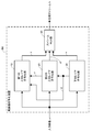
- FIG. 10 is a block diagram showing a configuration of upper layer encoding section 210.
- Upper layer encoding section 210 includes color format conversion section 211, color predicted value generation section 212, prediction value generation section 213, DCT / quantization section 214, inverse DCT / inverse quantization section 215, entropy encoding section 216, and A local memory 217 is provided.
- the prediction value generation unit 213, the DCT / quantization unit 214, the inverse DCT / inverse quantization unit 215, the entropy encoding unit 216, and the local memory 217 are the prediction value generation unit 12, DCT / quantum shown in FIG. It operates in the same manner as the conversion unit 13, inverse DCT / inverse quantization unit 14, entropy encoding unit 15, and local memory 16.
- the color format conversion unit 211 receives the local decoded video ⁇ of the lower layer as an input.
- the local decoded video ⁇ of the lower layer is a video in the YUV format. Therefore, the color format conversion unit 211 calculates the pixel values of the R component, the G component, and the B component based on the weighted sum of the pixel values of the Y component, the U component, and the V component of the local decoded video ⁇ of the lower layer. Is obtained and output as a converted image ⁇ in RGB format.
- the color prediction value generation unit 212 receives the converted video ⁇ as input.
- the color prediction value generation unit 212 generates the remaining two component prediction values based on one of the RGB components.
- the Y component and the G component are visually important components in the YUV format and the RGB format, and the Y component and the G component have substantially the same amount of information. That is, the Y component and the G component are in a pair relationship. Therefore, in the present embodiment, the G component is assumed as a reference. Then, the color prediction value generation unit 212 uses the G component as the Y component of the color information scalable prediction unit 11 illustrated in FIG. 2, and is similar to the case where the color information scalable prediction unit 11 generates the UV component prediction value h. The method predicts the RB component. Then, the reference color component (G component) in the upper layer and the predicted values of the remaining components (RB component) are output as predicted values ⁇ .
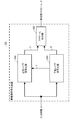
- FIG. 11 is a block diagram showing a configuration of lower layer encoding section 220.
- the lower layer encoding unit 220 includes a predicted value generation unit 221, a DCT / quantization unit 222, an inverse DCT / inverse quantization unit 223, an entropy encoding unit 224, a local memory 225, and a color format conversion unit 226.
- the prediction value generation unit 221, the DCT / quantization unit 222, the inverse DCT / inverse quantization unit 223, the entropy encoding unit 224, and the local memory 225 are respectively the prediction value generation unit 32, the DCT / quantum illustrated in FIG. It operates in the same manner as the conversion unit 33, the inverse DCT / inverse quantization unit 34, the entropy encoding unit 35, and the local memory 36.
- the color format conversion unit 226 receives the input video ⁇ .
- the input video ⁇ is an RGB format video. Therefore, the color format conversion unit 226 obtains the pixel values of the Y component, the U component, and the V component from the weighted sum of the pixel values of the R component, the G component, and the B component of the input video ⁇ , Output as converted image ⁇ in YUV format.
- FIG. 12 is a block diagram showing a configuration of a video decoding device DD according to the second embodiment of the present invention.
- the video decoding device DD decodes the compressed stream ⁇ generated in the video encoding device CC, and generates an upper layer output video ⁇ and a lower layer output video ⁇ .
- This video decoding device DD includes an upper layer decoding unit 310, a lower layer decoding unit 320, and a stream DEMUX unit 330.
- the stream DEMUX unit 330 receives the compressed stream ⁇ .
- the stream DEMUX unit 330 extracts higher layer encoding information ⁇ and lower layer encoding information ⁇ from the compressed stream ⁇ . Then, upper layer encoding information ⁇ is output to upper layer decoding section 310, and lower layer encoding information ⁇ is output to lower layer decoding section 320.
- FIG. 13 is a block diagram showing the configuration of the upper layer decoding unit 310.
- the upper layer decoding unit 310 includes an entropy decoding unit 311, a color format conversion unit 312, a color prediction value generation unit 313, an inverse DCT / inverse quantization unit 314, a prediction value generation unit 315, and a local memory 316.
- the entropy decoding unit 311, the inverse DCT / inverse quantization unit 314, the prediction value generation unit 315, and the local memory 316 are respectively the entropy decoding unit 111, the inverse DCT / inverse quantization unit 113, and the prediction value generation illustrated in FIG.
- the unit 114 and the local memory 115 operate in the same manner.
- the color format conversion unit 312 receives a decoded image ⁇ of a later-described lower layer output from the lower layer decoding unit 320.
- the decoded image ⁇ in the lower layer is a video in the YUV format. Therefore, the color format conversion unit 312 converts the pixel values of the R component, the G component, and the B component according to the weighted sum of the pixel values of the Y component, U component, and V component of the decoded image ⁇ in the lower layer. Obtained and output as a decoded image ⁇ of the lower layer of the RGB format.
- the color prediction value generation unit 313 receives the decoded image ⁇ of the lower layer as an input.
- the color prediction value generation unit 313 generates a color prediction value in the same manner as the color prediction value generation unit 212 illustrated in FIG. Then, the reference color component (G component) and the predicted value of the remaining component (RB component) in the lower layer are output as the predicted value ⁇ .
- FIG. 14 is a block diagram showing the configuration of the lower layer decoding unit 320.
- the lower layer decoding unit 320 includes an entropy decoding unit 321, an inverse DCT / inverse quantization unit 322, a predicted value generation unit 323, and a local memory 324.
- the entropy decoding unit 321, the inverse DCT / inverse quantization unit 322, the predicted value generation unit 323, and the local memory 324 are respectively the entropy decoding unit 131, the inverse DCT / inverse quantization unit 133, and the predicted value generation illustrated in FIG.
- the unit 134 and the local memory 135 operate in the same manner.
- the moving image encoding device CC performs inter-layer prediction based on inter-color component prediction using a pair relationship between the Y component and the G component. According to this, it is possible to predict the video of the upper layer with high accuracy using the video of the lower layer. Therefore, even if the upper layer video (RGB format video) and the lower layer video (YUV format video) have the same design but different video formats, these videos can be efficiently converted into one compressed stream ⁇ . It can be compressed. Therefore, for example, both the lower layer can be efficiently compressed using the broadcast video format and the upper layer as the material video format.
- the moving picture encoding device CC can add information for compensating for deterioration in the lower layer (SNR scalability) in the upper layer even for color components having the same video format between layers.
- the video decoding device DD performs inter-layer prediction based on inter-color component prediction using the paired relationship between the Y component and the G component. According to this, it is possible to predict the video of the upper layer with high accuracy using the video of the lower layer. Therefore, it is possible to decode videos having different video formats, such as the upper layer output video ⁇ and the lower layer output video ⁇ , from one compressed stream ⁇ .
- the processing of the moving image encoding devices AA and CC and the moving image decoding devices BB and DD of the present invention is recorded on a computer-readable non-transitory recording medium, and the program recorded on the recording medium is recorded as a moving image.
- the present invention can be realized by causing the encoding devices AA and CC and the video decoding devices BB and DD to read and execute them.
- a nonvolatile memory such as an EPROM or a flash memory
- a magnetic disk such as a hard disk, a CD-ROM, or the like
- reading and execution of the program recorded on the recording medium is performed by a processor provided in the moving image encoding devices AA and CC and the moving image decoding devices BB and DD.
- the above-described program may be transmitted from the moving image encoding devices AA, CC and the moving image decoding devices BB, DD storing the program in a storage device or the like via a transmission medium or by a transmission wave in the transmission medium. May be transmitted to other computer systems.
- the “transmission medium” for transmitting the program refers to a medium having a function of transmitting information, such as a network (communication network) such as the Internet or a communication line (communication line) such as a telephone line.
- the above-described program may be for realizing a part of the above-described function. Furthermore, what can implement
- a YUV 4: 4: 4 format video is input as the input video a.
- the present invention is not limited to this.
- a YUV 4: 2: 2 format video is input. May be.
- the color information sampling unit 37 in FIG. 4 generates a YUV 4: 2: 0 format video.
- the present invention is not limited to this, and the present invention is also applied to cases where, for example, three hierarchies or four hierarchies exist. it can. Even when there are three or more layers, the upper layer may be encoded and decoded sequentially from the lower layer as in the first embodiment.
- the predicted value generation unit 22 when the difference between the Y component of the input video a and the Y component of the local decoded video g of the lower layer is smaller than a predetermined threshold, the predicted value generation unit 22 The same value as that of the input video a may be output as the predicted value p. According to this, if the image quality of the local decoded video g of the lower layer is sufficiently good for the Y component, the local decoded video g of the lower layer is replaced with the Y component of the upper layer. Then, the difference information between the input video a and the predicted value p input to the DCT / quantization unit 23 becomes zero, and the entropy encoding unit 25 encodes only the prediction information q. Further, additional information and special processing are not required for the generated compressed stream b in the moving picture decoding apparatus BB described later.
- the number of bits expressed in the upper layer and the number of bits expressed in the lower layer are the same.
- the present invention is not limited to this, and may be different.
- the scalability of the number of representation bits can be realized in a video format hierarchical structure in which the number of bits of the upper layer includes the number of bits of the lower layer.
- the YUV format video is described, and in the second embodiment, the RGB format video and the YUV format video are described.
- the present invention is not limited to this, and the present invention can also be applied to scalability between other color spaces such as Lab and CMYK.
Abstract
Description
(1) 本発明は、入力映像に対するスケーラブル符号化が可能な動画像符号化装置であって、前記入力映像を、当該入力映像の映像フォーマットとは異なる映像フォーマットの映像に変換して、変換後映像を生成する映像フォーマット変換手段と、前記映像フォーマット変換手段により前記変換後映像を生成する際に失われた情報を予測する符号化側予測手段と、前記符号化側予測手段による予測結果を用いて、前記入力映像を符号化する第1の符号化手段と、前記映像フォーマット変換手段により生成された前記変換後映像を符号化する第2の符号化手段と、前記第1の符号化手段による符号化結果と、前記第2の符号化手段による符号化結果と、を多重化して、映像フォーマットに関するスケーラビリティを有する圧縮データを生成する多重化手段と、を備えることを特徴とする動画像符号化装置を提案している。 The present invention proposes the following matters in order to solve the above problems.
(1) The present invention is a moving image coding apparatus capable of scalable coding of an input video, wherein the input video is converted into a video having a video format different from the video format of the input video, and after the conversion Using video format conversion means for generating video, encoding side prediction means for predicting information lost when the converted video is generated by the video format conversion means, and prediction results by the encoding side prediction means A first encoding unit that encodes the input video, a second encoding unit that encodes the converted video generated by the video format conversion unit, and a first encoding unit. The encoded result and the encoded result by the second encoding means are multiplexed to generate compressed data having scalability related to the video format. And a video encoding device characterized by comprising multiplexing means.
[動画像符号化装置AAの構成および動作]
図1は、本発明の第1実施形態に係る動画像符号化装置AAの構成を示すブロック図である。動画像符号化装置AAは、入力された入力映像aから、2つの映像フォーマットの映像を生成し、1つの映像ストリームに多重化して、圧縮ストリームbとして出力する。 <First Embodiment>
[Configuration and Operation of Video Encoding Device AA]
FIG. 1 is a block diagram showing a configuration of a video encoding apparatus AA according to the first embodiment of the present invention. The video encoding device AA generates videos in two video formats from the input video a that has been input, multiplexes them into one video stream, and outputs them as a compressed stream b.
図2は、第1の上位レイヤ符号化部10の構成を示すブロック図である。第1の上位レイヤ符号化部10は、色情報スケーラブル予測部11、予測値生成部12、DCT/量子化部13、逆DCT/逆量子化部14、エントロピー符号化部15、およびローカルメモリ16を備える。 (Configuration and operation of first higher layer encoding unit 10)
FIG. 2 is a block diagram showing the configuration of the first higher
図3は、第2の上位レイヤ符号化部20の構成を示すブロック図である。第2の上位レイヤ符号化部20は、予測値生成部22、DCT/量子化部23、逆DCT/逆量子化部24、エントロピー符号化部25、およびローカルメモリ26を備える。 (Configuration and operation of second higher layer encoding unit 20)
FIG. 3 is a block diagram showing the configuration of the second higher
図4は、下位レイヤ符号化部30の構成を示すブロック図である。下位レイヤ符号化部30は、予測値生成部32、DCT/量子化部33、逆DCT/逆量子化部34、エントロピー符号化部35、ローカルメモリ36、および色情報サンプリング部37を備える。 (Configuration and operation of lower layer encoding unit 30)
FIG. 4 is a block diagram illustrating a configuration of the lower
図5は、本発明の第1実施形態に係る動画像復号装置BBの構成を示すブロック図である。動画像復号装置BBは、動画像符号化装置AAにおいて生成された圧縮ストリームbを復号して、上位レイヤ出力映像Aおよび下位レイヤ出力映像Bを生成する。この動画像復号装置BBは、第1の上位レイヤ復号部110、第2の上位レイヤ復号部120、下位レイヤ復号部130、およびストリームDEMUX部140を備える。上位レイヤ出力映像Aは、第1の上位レイヤ復号部110から出力される後述の上位レイヤのUV成分に関するデコード画像A1と、第2の上位レイヤ復号部120から出力される後述の上位レイヤのY成分に関するデコード画像A2と、で構成される。 [Configuration and Operation of Video Decoding Device BB]
FIG. 5 is a block diagram showing a configuration of the video decoding device BB according to the first embodiment of the present invention. The video decoding device BB decodes the compressed stream b generated by the video encoding device AA, and generates an upper layer output video A and a lower layer output video B. This video decoding device BB includes a first upper
図6は、第1の上位レイヤ復号部110の構成を示すブロック図である。第1の上位レイヤ復号部110は、エントロピー復号部111、色情報スケーラブル予測部112、逆DCT/逆量子化部113、予測値生成部114、およびローカルメモリ115を備える。 (Configuration and operation of first higher layer decoding section 110)
FIG. 6 is a block diagram showing a configuration of first higher
図7は、第2の上位レイヤ復号部120の構成を示すブロック図である。第2の上位レイヤ復号部120は、エントロピー復号部121、逆DCT/逆量子化部123、予測値生成部124、およびローカルメモリ125を備える。 (Configuration and operation of second higher layer decoding section 120)
FIG. 7 is a block diagram showing a configuration of the second higher
図8は、下位レイヤ復号部130の構成を示すブロック図である。下位レイヤ復号部130は、エントロピー復号部131、逆DCT/逆量子化部133、予測値生成部134、およびローカルメモリ135を備える。 (Configuration and operation of lower layer decoding unit 130)
FIG. 8 is a block diagram illustrating a configuration of the lower
[動画像符号化装置CCの構成および動作]
図9は、本発明の第2実施形態に係る動画像符号化装置CCの構成を示すブロック図である。動画像符号化装置CCは、入力された入力映像αから、2つの映像フォーマットの映像を生成し、1つの映像ストリームに多重化して、圧縮ストリームβとして出力する。 <Second Embodiment>
[Configuration and Operation of Video Encoding Device CC]
FIG. 9 is a block diagram showing a configuration of a video encoding device CC according to the second embodiment of the present invention. The moving image encoding device CC generates videos in two video formats from the input video α that has been input, multiplexes the video into one video stream, and outputs it as a compressed stream β.
図10は、上位レイヤ符号化部210の構成を示すブロック図である。上位レイヤ符号化部210は、色フォーマット変換部211、色予測値生成部212、予測値生成部213、DCT/量子化部214、逆DCT/逆量子化部215、エントロピー符号化部216、およびローカルメモリ217を備える。 (Configuration and operation of upper layer encoding section 210)
FIG. 10 is a block diagram showing a configuration of upper
図11は、下位レイヤ符号化部220の構成を示すブロック図である。下位レイヤ符号化部220は、予測値生成部221、DCT/量子化部222、逆DCT/逆量子化部223、エントロピー符号化部224、ローカルメモリ225、および色フォーマット変換部226を備える。 (Configuration and operation of lower layer encoding section 220)
FIG. 11 is a block diagram showing a configuration of lower
図12は、本発明の第2実施形態に係る動画像復号装置DDの構成を示すブロック図である。動画像復号装置DDは、動画像符号化装置CCにおいて生成された圧縮ストリームβを復号して、上位レイヤ出力映像κおよび下位レイヤ出力映像λを生成する。この動画像復号装置DDは、上位レイヤ復号部310、下位レイヤ復号部320、およびストリームDEMUX部330を備える。 [Configuration and Operation of Video Decoding Device DD]
FIG. 12 is a block diagram showing a configuration of a video decoding device DD according to the second embodiment of the present invention. The video decoding device DD decodes the compressed stream β generated in the video encoding device CC, and generates an upper layer output video κ and a lower layer output video λ. This video decoding device DD includes an upper
図13は、上位レイヤ復号部310の構成を示すブロック図である。上位レイヤ復号部310は、エントロピー復号部311、色フォーマット変換部312、色予測値生成部313、逆DCT/逆量子化部314、予測値生成部315、およびローカルメモリ316を備える。 (Configuration and operation of upper layer decoding section 310)
FIG. 13 is a block diagram showing the configuration of the upper
図14は、下位レイヤ復号部320の構成を示すブロック図である。下位レイヤ復号部320は、エントロピー復号部321、逆DCT/逆量子化部322、予測値生成部323、およびローカルメモリ324を備える。 (Configuration and operation of lower layer decoding section 320)
FIG. 14 is a block diagram showing the configuration of the lower
20・・・第2の上位レイヤ符号化部
30、220・・・下位レイヤ符号化部
40、230・・・ストリームMUX部
110・・・第1の上位レイヤ復号部
120・・・第2の上位レイヤ復号部
130、320・・・下位レイヤ復号部
140、330・・・ストリームDEMUX部
210・・・上位レイヤ符号化部
310・・・上位レイヤ復号部
AA、CC・・・動画像符号化装置
BB、DD・・・動画像復号装置 DESCRIPTION OF
Claims (25)
- 入力映像に対するスケーラブル符号化が可能な動画像符号化装置であって、
前記入力映像を、当該入力映像の映像フォーマットとは異なる映像フォーマットの映像に変換して、変換後映像を生成する映像フォーマット変換手段と、
前記映像フォーマット変換手段により前記変換後映像を生成する際に失われた情報を予測する符号化側予測手段と、
前記符号化側予測手段による予測結果を用いて、前記入力映像を符号化する第1の符号化手段と、
前記映像フォーマット変換手段により生成された前記変換後映像を符号化する第2の符号化手段と、
前記第1の符号化手段による符号化結果と、前記第2の符号化手段による符号化結果と、を多重化して、映像フォーマットに関するスケーラビリティを有する圧縮データを生成する多重化手段と、を備えることを特徴とする動画像符号化装置。 A video encoding device capable of scalable encoding of input video,
Video format conversion means for converting the input video into a video having a video format different from the video format of the input video, and generating a converted video;
Encoding side prediction means for predicting information lost when the converted video is generated by the video format conversion means;
First encoding means for encoding the input video using a prediction result by the encoding side prediction means;
Second encoding means for encoding the converted video generated by the video format conversion means;
A multiplexing unit that multiplexes the encoding result of the first encoding unit and the encoding result of the second encoding unit to generate compressed data having scalability related to a video format; A video encoding apparatus characterized by the above. - 前記映像フォーマット変換手段は、前記変換後映像として、前記入力映像のフォーマットと同じフォーマットで、かつ、当該入力映像より色情報の少ない映像フォーマットの映像を生成することを特徴とする請求項1に記載の動画像符号化装置。 2. The video format conversion unit according to claim 1, wherein the video format conversion unit generates a video of a video format having the same format as the format of the input video and having less color information than the input video as the converted video. Video encoding device.
- 前記第1の符号化手段は、既存の標準方式によりベースレイヤの符号化を行い、
前記符号化側予測手段は、前記ベースレイヤの復号画像の輝度成分の画素値を用いて、前記失われた色情報を予測することを特徴とする請求項2に記載の動画像符号化装置。 The first encoding means performs base layer encoding according to an existing standard method,
The moving image encoding apparatus according to claim 2, wherein the encoding side prediction means predicts the lost color information using a pixel value of a luminance component of a decoded image of the base layer. - 前記符号化側予測手段は、前記入力映像についての復号画像の輝度成分の画素値と、前記変換後映像についての復号画像の輝度成分の画素値と、を用いて、多項式近似に基づき、前記映像フォーマット変換手段により当該入力映像から当該変換後映像を生成した際に失われた色差成分の予測値を生成することを特徴とする請求項3に記載の動画像符号化装置。 The encoding side prediction means uses the pixel value of the luminance component of the decoded image for the input video and the pixel value of the luminance component of the decoded image for the converted video, based on polynomial approximation, based on the polynomial approximation 4. The moving picture coding apparatus according to claim 3, wherein a predicted value of the color difference component lost when the converted video is generated from the input video by the format conversion means.
- 前記符号化側予測手段は、前記入力映像についての復号画像の輝度成分の画素値と、前記変換後映像についての復号画像の輝度成分の画素値と、を用いて、処理画素値の誤差が最小となる補間フィルタに基づき、前記映像フォーマット変換手段により当該入力映像から当該変換後映像を生成した際に失われた色差成分の予測値を生成することを特徴とする請求項3に記載の動画像符号化装置。 The encoding side prediction means uses the pixel value of the luminance component of the decoded image for the input video and the pixel value of the luminance component of the decoded image for the converted video to minimize the error of the processing pixel value 4. The moving image according to claim 3, wherein a predicted value of a color difference component lost when the converted video is generated from the input video by the video format conversion unit based on the interpolation filter Encoding device.
- 前記符号化側予測手段は、前記入力映像についての復号画像の輝度成分の画素値と、前記変換後映像についての復号画像の輝度成分の画素値と、を用いて、非線形補間処理に基づき、前記映像フォーマット変換手段により当該入力映像から当該変換後映像を生成した際に失われた色差成分の予測値を生成することを特徴とする請求項3に記載の動画像符号化装置。 The encoding side prediction means uses the pixel value of the luminance component of the decoded image for the input video and the pixel value of the luminance component of the decoded image for the converted video, based on nonlinear interpolation processing, 4. The moving picture encoding apparatus according to claim 3, wherein a predicted value of the color difference component lost when the converted video is generated from the input video by the video format conversion means.
- 前記映像フォーマット変換手段は、前記変換後映像として、前記入力映像のフォーマットと異なるフォーマットで、かつ、1画素あたりのデータ量が当該入力映像より少ない映像フォーマットの映像を生成することを特徴とする請求項1に記載の動画像符号化装置。 The video format conversion means generates, as the converted video, a video having a format different from the format of the input video and having a data amount per pixel smaller than that of the input video. Item 4. The moving image encoding device according to Item 1.
- 前記第1の符号化手段は、既存の標準方式によりベースレイヤの符号化を行い、
前記符号化側予測手段は、前記ベースレイヤの復号画像を構成する複数の成分のうちの1つの画素値を用いて、前記失われた情報を予測することを特徴とする請求項7に記載の動画像符号化装置。 The first encoding means performs base layer encoding according to an existing standard method,
The said encoding side prediction means predicts the said lost information using one pixel value of the some components which comprise the decoded image of the said base layer, The said loss information is characterized by the above-mentioned. Video encoding device. - 前記入力映像についての復号画像を構成する複数の成分のうちの1つである特定成分と、前記変換後映像についての復号画像を構成する複数の成分のうちの1つである所定成分と、は対関係にあり、
前記符号化側予測手段は、前記入力映像についての復号画像の前記特定成分の画素値と、前記変換後映像についての復号画像の前記所定成分の画素値と、を用いて、多項式近似に基づき、前記映像フォーマット変換手段により当該入力映像から当該変換後映像を生成した際に失われた成分の予測値を生成することを特徴とする請求項8に記載の動画像符号化装置。 A specific component that is one of a plurality of components constituting a decoded image for the input video and a predetermined component that is one of a plurality of components constituting a decoded image for the converted video are: In a relationship
The encoding side prediction means uses the pixel value of the specific component of the decoded image for the input video and the pixel value of the predetermined component of the decoded image for the converted video, based on polynomial approximation, 9. The moving picture encoding apparatus according to claim 8, wherein a predicted value of a component lost when the converted video is generated from the input video by the video format conversion unit. - 前記入力映像についての復号画像を構成する複数の成分のうちの1つである特定成分と、前記変換後映像についての復号画像を構成する複数の成分のうちの1つである所定成分と、は対関係にあり、
前記符号化側予測手段は、前記入力映像についての復号画像の前記特定成分の画素値と、前記変換後映像についての復号画像の前記所定成分の画素値と、を用いて、処理画素値の誤差が最小となる補間フィルタに基づき、前記映像フォーマット変換手段により当該入力映像から当該変換後映像を生成した際に失われた成分の予測値を生成することを特徴とする請求項8に記載の動画像符号化装置。 A specific component that is one of a plurality of components constituting a decoded image for the input video and a predetermined component that is one of a plurality of components constituting a decoded image for the converted video are: In a relationship
The encoding side prediction means uses the pixel value of the specific component of the decoded image for the input video and the pixel value of the predetermined component of the decoded image for the converted video to generate an error in the processing pixel value 9. The moving image according to claim 8, wherein a predicted value of a component lost when the converted video is generated from the input video by the video format conversion unit based on an interpolation filter that minimizes the video. Image encoding device. - 前記入力映像についての復号画像を構成する複数の成分のうちの1つである特定成分と、前記変換後映像についての復号画像を構成する複数の成分のうちの1つである所定成分と、は対関係にあり、
前記符号化側予測手段は、前記入力映像についての復号画像の前記特定成分の画素値と、前記変換後映像についての復号画像の前記所定成分の画素値と、を用いて、非線形補間処理に基づき、前記映像フォーマット変換手段により当該入力映像から当該変換後映像を生成した際に失われた成分の予測値を生成することを特徴とする請求項8に記載の動画像符号化装置。 A specific component that is one of a plurality of components constituting a decoded image for the input video and a predetermined component that is one of a plurality of components constituting a decoded image for the converted video are: In a relationship
The encoding side prediction means uses the pixel value of the specific component of the decoded image for the input video and the pixel value of the predetermined component of the decoded image for the converted video based on nonlinear interpolation processing. 9. The moving picture encoding apparatus according to claim 8, wherein a predicted value of a component lost when the converted video is generated from the input video by the video format conversion means. - 請求項1から6のいずれかの動画像符号化装置で生成された圧縮データに対するスケーラブル復号が可能な動画像復号装置であって、
前記圧縮データから、映像の符号化結果を映像フォーマットごとに取り出す逆多重化手段と、
前記逆多重化手段により取り出された映像フォーマットごとの符号化結果を復号する復号手段と、
前記映像フォーマット変換手段により前記入力映像から前記変換後映像を生成した際に失われた情報を予測する復号側予測手段と、
前記復号手段により復号された映像と、前記復号側予測手段による予測結果と、を用いて、前記入力映像を求める第1の映像出力手段と、
前記復号手段により復号された映像に基づいて、前記変換後映像を求める第2の映像出力手段と、を備えることを特徴とする動画像復号装置。 A video decoding device capable of scalable decoding on compressed data generated by the video encoding device according to any one of claims 1 to 6,
Demultiplexing means for extracting a video encoding result for each video format from the compressed data;
Decoding means for decoding the encoding result for each video format extracted by the demultiplexing means;
Decoding side prediction means for predicting information lost when the converted video is generated from the input video by the video format conversion means;
First video output means for obtaining the input video using the video decoded by the decoding means and the prediction result by the decoding-side prediction means;
And a second video output means for obtaining the converted video based on the video decoded by the decoding means. - 前記復号手段は、既存の標準方式により符号化されたベースレイヤの符号化結果の復号と、前記逆多重化手段により取り出された符号化結果のうち当該ベースレイヤとは異なるエンハンスメントレイヤの符号化結果の復号と、を行い、
前記復号側予測手段は、前記ベースレイヤの復号画像の輝度成分の画素値を用いて、前記失われた色情報を予測することを特徴とする請求項12に記載の動画像復号装置。 The decoding means includes decoding of a base layer encoding result encoded by an existing standard method, and an encoding result of an enhancement layer different from the base layer among the encoding results extracted by the demultiplexing means And decrypting
13. The moving picture decoding apparatus according to claim 12, wherein the decoding side prediction unit predicts the lost color information using a pixel value of a luminance component of the decoded image of the base layer. - 前記復号側予測手段は、前記ベースレイヤの復号画像の輝度成分の画素値と、前記エンハンスメントレイヤの復号画像の輝度成分の画素値と、を用いて、多項式近似に基づき、前記映像フォーマット変換手段により前記入力映像から前記変換後映像を生成した際に失われた色差成分の予測値を生成することを特徴とする請求項13に記載の動画像復号装置。 The decoding side prediction means uses the pixel value of the luminance component of the decoded image of the base layer and the pixel value of the luminance component of the decoded image of the enhancement layer, based on polynomial approximation, by the video format conversion means. 14. The moving picture decoding apparatus according to claim 13, wherein a prediction value of a color difference component lost when the converted video is generated from the input video is generated.
- 前記復号側予測手段は、前記ベースレイヤの復号画像の輝度成分の画素値と、前記エンハンスメントレイヤの復号画像の輝度成分の画素値と、を用いて、処理画素値の誤差が最小となる補間フィルタに基づき、前記映像フォーマット変換手段により前記入力映像から前記変換後映像を生成した際に失われた色差成分の予測値を生成することを特徴とする請求項13に記載の動画像復号装置。 The decoding-side prediction means uses the pixel value of the luminance component of the decoded image of the base layer and the pixel value of the luminance component of the decoded image of the enhancement layer, and an interpolation filter that minimizes the error of the processing pixel value 14. The moving picture decoding apparatus according to claim 13, wherein a predicted value of a color difference component lost when the converted video is generated from the input video by the video format conversion unit is generated.
- 前記復号側予測手段は、前記ベースレイヤの復号画像の輝度成分の画素値と、前記エンハンスメントレイヤの復号画像の輝度成分の画素値と、を用いて、非線形補間処理に基づき、前記映像フォーマット変換手段により前記入力映像から前記変換後映像を生成した際に失われた色差成分の予測値を生成することを特徴とする請求項13に記載の動画像復号装置。 The decoding-side prediction unit uses the pixel value of the luminance component of the decoded image of the base layer and the pixel value of the luminance component of the decoded image of the enhancement layer, based on a nonlinear interpolation process, and the video format conversion unit 14. The moving picture decoding apparatus according to claim 13, wherein a predicted value of a color difference component lost when the converted video is generated from the input video is generated.
- 請求項1、7から11のいずれかの動画像符号化装置で生成された圧縮データに対するスケーラブル復号が可能な動画像復号装置であって、
前記圧縮データから、映像の符号化結果を映像フォーマットごとに取り出す逆多重化手段と、
前記逆多重化手段により取り出された映像フォーマットごとの符号化結果を復号する復号手段と、
前記映像フォーマット変換手段により前記入力映像から前記変換後映像を生成した際に失われた情報を予測する復号側予測手段と、
前記復号手段により復号された映像と、前記復号側予測手段による予測結果と、を用いて、前記入力映像を求める第1の映像出力手段と、
前記復号手段により復号された映像に基づいて、前記変換後映像を求める第2の映像出力手段と、を備えることを特徴とする動画像復号装置。 A video decoding device capable of scalable decoding with respect to compressed data generated by the video encoding device according to any one of claims 1 to 7.
Demultiplexing means for extracting a video encoding result for each video format from the compressed data;
Decoding means for decoding the encoding result for each video format extracted by the demultiplexing means;
Decoding side prediction means for predicting information lost when the converted video is generated from the input video by the video format conversion means;
First video output means for obtaining the input video using the video decoded by the decoding means and the prediction result by the decoding-side prediction means;
And a second video output means for obtaining the converted video based on the video decoded by the decoding means. - 前記復号手段は、既存の標準方式により符号化されたベースレイヤの符号化結果の復号と、前記逆多重化手段により取り出された符号化結果のうち当該ベースレイヤとは異なるエンハンスメントレイヤの符号化結果の復号と、を行い、
前記復号側予測手段は、前記ベースレイヤの復号画像の前記特定成分の画素値を用いて、前記失われた情報を予測することを特徴とする請求項17に記載の動画像復号装置。 The decoding means includes decoding of a base layer encoding result encoded by an existing standard method, and an encoding result of an enhancement layer different from the base layer among the encoding results extracted by the demultiplexing means And decrypting
The moving picture decoding apparatus according to claim 17, wherein the decoding side prediction unit predicts the lost information using a pixel value of the specific component of the decoded image of the base layer. - 前記復号側予測手段は、前記ベースレイヤの復号画像の前記特定成分の画素値と、前記エンハンスメントレイヤの復号画像の前記所定成分の画素値と、を用いて、多項式近似に基づき、前記映像フォーマット変換手段により前記入力映像から前記変換後映像を生成した際に失われた成分の予測値を生成することを特徴とする請求項18に記載の動画像復号装置。 The decoding side prediction means uses the pixel value of the specific component of the decoded image of the base layer and the pixel value of the predetermined component of the decoded image of the enhancement layer based on polynomial approximation to convert the video format 19. The moving picture decoding apparatus according to claim 18, wherein a predicted value of a component lost when the converted video is generated from the input video by means.
- 前記復号側予測手段は、前記ベースレイヤの復号画像の前記特定成分の画素値と、前記エンハンスメントレイヤの復号画像の前記所定成分の画素値と、を用いて、処理画素値の誤差が最小となる補間フィルタに基づき、前記映像フォーマット変換手段により前記入力映像から前記変換後映像を生成した際に失われた成分の予測値を生成することを特徴とする請求項18に記載の動画像復号装置。 The decoding-side prediction unit uses the pixel value of the specific component of the decoded image of the base layer and the pixel value of the predetermined component of the decoded image of the enhancement layer to minimize the error of the processing pixel value 19. The moving picture decoding apparatus according to claim 18, wherein a predicted value of a component lost when the converted video is generated from the input video by the video format conversion unit based on an interpolation filter.
- 前記復号側予測手段は、前記ベースレイヤの復号画像の前記特定成分の画素値と、前記エンハンスメントレイヤの復号画像の前記所定成分の画素値と、を用いて、非線形補間処理に基づき、前記映像フォーマット変換手段により前記入力映像から前記変換後映像を生成した際に失われた成分の予測値を生成することを特徴とする請求項18に記載の動画像復号装置。 The decoding-side prediction means uses the pixel value of the specific component of the decoded image of the base layer and the pixel value of the predetermined component of the decoded image of the enhancement layer based on a nonlinear interpolation process to generate the video format. 19. The moving picture decoding apparatus according to claim 18, wherein a prediction value of a component lost when the converted video is generated from the input video by a conversion unit is generated.
- 映像フォーマット変換手段、符号化側予測手段、第1の符号化手段、第2の符号化手段、および多重化手段を備え、入力映像に対するスケーラブル符号化が可能な動画像符号化装置における動画像符号化方法であって、
前記映像フォーマット変換手段が、前記入力映像を、当該入力映像の映像フォーマットとは異なる映像フォーマットの映像に変換して、変換後映像を生成する第1のステップと、
前記符号化側予測手段が、前記映像フォーマット変換手段により前記変換後映像を生成する際に失われた情報を予測する第2のステップと、
前記第1の符号化手段が、前記符号化側予測手段による予測結果を用いて、前記入力映像を符号化する第3のステップと、
前記第2の符号化手段が、前記映像フォーマット変換手段により変換された映像を符号化する第4のステップと、
前記多重化手段が、前記第1の符号化手段による符号化結果と、前記第2の符号化手段による符号化結果と、を多重化して、映像フォーマットに関するスケーラビリティを有する圧縮データを生成する第5のステップと、を備えることを特徴とする動画像符号化方法。 A moving picture code in a moving picture coding apparatus comprising a video format conversion means, a coding side prediction means, a first coding means, a second coding means, and a multiplexing means and capable of scalable coding of an input video A method of
A first step in which the video format converting means converts the input video into a video having a video format different from the video format of the input video, and generates a converted video;
A second step in which the encoding side prediction means predicts information lost when the converted video is generated by the video format conversion means;
A third step in which the first encoding means encodes the input video using a prediction result by the encoding-side prediction means;
A fourth step in which the second encoding means encodes the video converted by the video format conversion means;
The multiplexing means multiplexes the result of encoding by the first encoding means and the result of encoding by the second encoding means to generate compressed data having scalability related to the video format. And a video encoding method comprising the steps of: - 逆多重化手段、復号手段、復号側予測手段、第1の映像出力手段、および第2の映像出力手段を備え、請求項22の動画像符号化装置で生成された圧縮データに対するスケーラブル復号が可能な動画像復号装置における動画像復号方法であって、
前記逆多重化手段が、前記圧縮データから、映像の符号化結果を映像フォーマットごとに取り出す第6のステップと、
前記復号手段が、前記逆多重化手段により取り出された映像フォーマットごとの符号化結果を復号する第7のステップと、
前記復号側予測手段が、前記映像フォーマット変換手段により前記入力映像から前記変換後映像を生成した際に失われた情報を予測する第8のステップと、
前記第1の映像出力手段が、前記復号手段により復号された映像と、前記復号側予測手段による予測結果と、を用いて、前記入力映像を求める第9のステップと、
前記第2の映像出力手段が、前記復号手段により復号された映像に基づいて、前記変換後映像を求める第10のステップと、を備えることを特徴とする動画像復号方法。 A demultiplexing unit, a decoding unit, a decoding side prediction unit, a first video output unit, and a second video output unit are provided, and scalable decoding can be performed on the compressed data generated by the moving picture encoding apparatus according to claim 22. A moving image decoding method in a moving image decoding apparatus,
A sixth step in which the demultiplexing means extracts a video encoding result for each video format from the compressed data;
A seventh step in which the decoding means decodes an encoding result for each video format extracted by the demultiplexing means;
An eighth step in which the decoding side prediction means predicts information lost when the converted video is generated from the input video by the video format conversion means;
A first step in which the first video output means obtains the input video by using the video decoded by the decoding means and the prediction result by the decoding-side prediction means;
A moving picture decoding method comprising: a tenth step in which the second video output means obtains the converted video based on the video decoded by the decoding means. - 映像フォーマット変換手段、符号化側予測手段、第1の符号化手段、第2の符号化手段、および多重化手段を備え、入力映像に対するスケーラブル符号化が可能な動画像符号化装置における動画像符号化方法を、コンピュータに実行させるためのプログラムであって、
前記映像フォーマット変換手段が、前記入力映像を、当該入力映像の映像フォーマットとは異なる映像フォーマットの映像に変換して、変換後映像を生成する第1のステップと、
前記符号化側予測手段が、前記映像フォーマット変換手段により前記変換後映像を生成する際に失われた情報を予測する第2のステップと、
前記第1の符号化手段が、前記符号化側予測手段による予測結果を用いて、前記入力映像を符号化する第3のステップと、
前記第2の符号化手段が、前記映像フォーマット変換手段により変換された映像を符号化する第4のステップと、
前記多重化手段が、前記第1の符号化手段による符号化結果と、前記第2の符号化手段による符号化結果と、を多重化して、映像フォーマットに関するスケーラビリティを有する圧縮データを生成する第5のステップと、をコンピュータに実行させるためのプログラム。 A moving picture code in a moving picture coding apparatus comprising a video format conversion means, a coding side prediction means, a first coding means, a second coding means, and a multiplexing means and capable of scalable coding of an input video A program for causing a computer to execute a computerization method,
A first step in which the video format converting means converts the input video into a video having a video format different from the video format of the input video, and generates a converted video;
A second step in which the encoding side prediction means predicts information lost when the converted video is generated by the video format conversion means;
A third step in which the first encoding means encodes the input video using a prediction result by the encoding-side prediction means;
A fourth step in which the second encoding means encodes the video converted by the video format conversion means;
The multiplexing means multiplexes the result of encoding by the first encoding means and the result of encoding by the second encoding means to generate compressed data having scalability related to the video format. Program for causing a computer to execute the above steps. - 逆多重化手段、復号手段、復号側予測手段、第1の映像出力手段、および第2の映像出力手段を備え、請求項24の動画像符号化装置で生成された圧縮データに対するスケーラブル復号が可能な動画像復号装置における動画像復号方法を、コンピュータに実行させるためのプログラムであって、
前記逆多重化手段が、前記圧縮データから、映像の符号化結果を映像フォーマットごとに取り出す第6のステップと、
前記復号手段が、前記逆多重化手段により取り出された映像フォーマットごとの符号化結果を復号する第7のステップと、
前記復号側予測手段が、前記映像フォーマット変換手段により前記入力映像から前記変換後映像を生成した際に失われた情報を予測する第8のステップと、
前記第1の映像出力手段が、前記復号手段により復号された映像と、前記復号側予測手段による予測結果と、を用いて、前記入力映像を求める第9のステップと、
前記第2の映像出力手段が、前記復号手段により復号された映像に基づいて、前記変換後映像を求める第10のステップと、をコンピュータに実行させるためのプログラム。 A demultiplexing unit, a decoding unit, a decoding side prediction unit, a first video output unit, and a second video output unit are provided, and scalable decoding can be performed on the compressed data generated by the moving picture encoding apparatus according to claim 24. A program for causing a computer to execute a video decoding method in a dynamic video decoding device,
A sixth step in which the demultiplexing means extracts a video encoding result for each video format from the compressed data;
A seventh step in which the decoding means decodes an encoding result for each video format extracted by the demultiplexing means;
An eighth step in which the decoding side prediction means predicts information lost when the converted video is generated from the input video by the video format conversion means;
A first step in which the first video output means obtains the input video by using the video decoded by the decoding means and the prediction result by the decoding-side prediction means;
A program for causing a computer to execute a tenth step in which the second video output means obtains the converted video based on the video decoded by the decoding means.
Priority Applications (4)
| Application Number | Priority Date | Filing Date | Title |
|---|---|---|---|
| US14/407,877 US20150181253A1 (en) | 2012-06-14 | 2013-06-07 | Video encoding apparatus, video decoding apparatus, video encoding method, video decoding method, and computer program |
| CN201380030288.0A CN104365094B (en) | 2012-06-14 | 2013-06-07 | Moving picture encoding device, animated image decoding apparatus, moving picture encoding method, animated image coding/decoding method and program |
| GB1422150.1A GB2518088A (en) | 2012-06-14 | 2013-06-07 | Video encoding device, video decoding device, video encoding method, video decoding method, and program |
| EP13804466.4A EP2863629A4 (en) | 2012-06-14 | 2013-06-07 | Video encoding device, video decoding device, video encoding method, video decoding method, and program |
Applications Claiming Priority (2)
| Application Number | Priority Date | Filing Date | Title |
|---|---|---|---|
| JP2012135117A JP5873395B2 (en) | 2012-06-14 | 2012-06-14 | Moving picture encoding apparatus, moving picture decoding apparatus, moving picture encoding method, moving picture decoding method, and program |
| JP2012-135117 | 2012-06-14 |
Publications (1)
| Publication Number | Publication Date |
|---|---|
| WO2013187334A1 true WO2013187334A1 (en) | 2013-12-19 |
Family
ID=49758157
Family Applications (1)
| Application Number | Title | Priority Date | Filing Date |
|---|---|---|---|
| PCT/JP2013/065875 WO2013187334A1 (en) | 2012-06-14 | 2013-06-07 | Video encoding device, video decoding device, video encoding method, video decoding method, and program |
Country Status (6)
| Country | Link |
|---|---|
| US (1) | US20150181253A1 (en) |
| EP (1) | EP2863629A4 (en) |
| JP (1) | JP5873395B2 (en) |
| CN (1) | CN104365094B (en) |
| GB (1) | GB2518088A (en) |
| WO (1) | WO2013187334A1 (en) |
Cited By (1)
| Publication number | Priority date | Publication date | Assignee | Title |
|---|---|---|---|---|
| CN105850134A (en) * | 2013-12-27 | 2016-08-10 | 索尼公司 | Image processing device and method |
Families Citing this family (4)
| Publication number | Priority date | Publication date | Assignee | Title |
|---|---|---|---|---|
| WO2014000168A1 (en) | 2012-06-27 | 2014-01-03 | Intel Corporation | Cross-layer cross-channel residual prediction |
| JP6233121B2 (en) * | 2014-03-17 | 2017-11-22 | 富士ゼロックス株式会社 | Image processing apparatus and image processing program |
| US10904534B2 (en) * | 2016-04-19 | 2021-01-26 | Dolby Laboratories Licensing Corporation | Enhancement layer masking for high-dynamic range video coding |
| CN112689197B (en) * | 2019-10-18 | 2022-07-08 | 腾讯科技(深圳)有限公司 | File format conversion method and device and computer storage medium |
Citations (4)
| Publication number | Priority date | Publication date | Assignee | Title |
|---|---|---|---|---|
| JP2002369220A (en) * | 2001-06-08 | 2002-12-20 | Victor Co Of Japan Ltd | Extended image coding method, extended image decoding method, extended image coder, extended image decoder and extended image recording medium |
| JP2005176383A (en) * | 2003-12-10 | 2005-06-30 | Microsoft Corp | Coding framework of color space |
| JP2010507941A (en) * | 2006-10-25 | 2010-03-11 | フラウンホーファー−ゲゼルシャフト・ツール・フェルデルング・デル・アンゲヴァンテン・フォルシュング・アインゲトラーゲネル・フェライン | Quality scalable coding method |
| JP2010531609A (en) * | 2007-06-27 | 2010-09-24 | サムスン エレクトロニクス カンパニー リミテッド | Video data encoding and / or decoding method, recording medium, and apparatus |
Family Cites Families (3)
| Publication number | Priority date | Publication date | Assignee | Title |
|---|---|---|---|---|
| AU2003278445A1 (en) * | 2002-11-13 | 2004-06-03 | Koninklijke Philips Electronics N.V. | Transmission system with colour depth scalability |
| US20050259729A1 (en) * | 2004-05-21 | 2005-11-24 | Shijun Sun | Video coding with quality scalability |
| KR100657268B1 (en) * | 2004-07-15 | 2006-12-14 | 학교법인 대양학원 | Scalable encoding and decoding method of color video, and apparatus thereof |
-
2012
- 2012-06-14 JP JP2012135117A patent/JP5873395B2/en not_active Expired - Fee Related
-
2013
- 2013-06-07 WO PCT/JP2013/065875 patent/WO2013187334A1/en active Application Filing
- 2013-06-07 GB GB1422150.1A patent/GB2518088A/en not_active Withdrawn
- 2013-06-07 US US14/407,877 patent/US20150181253A1/en not_active Abandoned
- 2013-06-07 CN CN201380030288.0A patent/CN104365094B/en not_active Expired - Fee Related
- 2013-06-07 EP EP13804466.4A patent/EP2863629A4/en not_active Withdrawn
Patent Citations (4)
| Publication number | Priority date | Publication date | Assignee | Title |
|---|---|---|---|---|
| JP2002369220A (en) * | 2001-06-08 | 2002-12-20 | Victor Co Of Japan Ltd | Extended image coding method, extended image decoding method, extended image coder, extended image decoder and extended image recording medium |
| JP2005176383A (en) * | 2003-12-10 | 2005-06-30 | Microsoft Corp | Coding framework of color space |
| JP2010507941A (en) * | 2006-10-25 | 2010-03-11 | フラウンホーファー−ゲゼルシャフト・ツール・フェルデルング・デル・アンゲヴァンテン・フォルシュング・アインゲトラーゲネル・フェライン | Quality scalable coding method |
| JP2010531609A (en) * | 2007-06-27 | 2010-09-24 | サムスン エレクトロニクス カンパニー リミテッド | Video data encoding and / or decoding method, recording medium, and apparatus |
Non-Patent Citations (5)
| Title |
|---|
| "Text of ISO/IEC 14496-10 Advanced Video Coding", ISO/IEC MPEG AND ITU-T VCEG |
| AJAY LUTHRA ET AL.: "Draft requirements for the scalable enhancement of HEVC", INTERNATIONAL ORGANISATION FOR STANDARDISATION ISO/IEC JTC1/ SC29/WG11 CODING OF MOVING PICTURES AND AUDIO, M22557, November 2011 (2011-11-01), GENEVA, SWITZERLAND, pages 1 - 8, XP030110933 * |
| JUNGSUN KIM ET AL.: "New intra chroma prediction using inter-channel correlation", JOINT COLLABORATIVE TEAM ON VIDEO CODING (JCT-VC) OF ITU-T SG16 WP3 AND ISO/IEC JTC1/SC29/WG11, JCTVC-B021, 2ND MEETING, July 2010 (2010-07-01), GENEVA, CH, pages 1 - 9, XP030007601 * |
| SANG HEON LEE ET AL.: "INTRA PREDICTION METHOD BASED ON THE LINEAR RELATIONSHIP BETWEEN THE CHANNELS FOR YUV 4:2:0 INTRA CODING", 16TH IEEE INTERNATIONAL CONFERENCE ON IMAGE PROCESSING (ICIP), November 2009 (2009-11-01), pages 1037 - 1040, XP031628426 * |
| See also references of EP2863629A4 |
Cited By (2)
| Publication number | Priority date | Publication date | Assignee | Title |
|---|---|---|---|---|
| CN105850134A (en) * | 2013-12-27 | 2016-08-10 | 索尼公司 | Image processing device and method |
| CN105850134B (en) * | 2013-12-27 | 2020-02-14 | 索尼公司 | Image processing apparatus and method |
Also Published As
| Publication number | Publication date |
|---|---|
| JP5873395B2 (en) | 2016-03-01 |
| US20150181253A1 (en) | 2015-06-25 |
| EP2863629A4 (en) | 2015-12-02 |
| EP2863629A1 (en) | 2015-04-22 |
| GB2518088A (en) | 2015-03-11 |
| CN104365094A (en) | 2015-02-18 |
| JP2013258651A (en) | 2013-12-26 |
| CN104365094B (en) | 2018-05-18 |
Similar Documents
| Publication | Publication Date | Title |
|---|---|---|
| CN111869212B (en) | Video decoding method, device and readable medium | |
| JP7271683B2 (en) | Encoders, decoders and corresponding intra-prediction methods | |
| TWI544787B (en) | Intra prediction modes for lossy coding when transform is skipped | |
| JP6274299B2 (en) | Video decoding apparatus and video decoding method | |
| KR102301083B1 (en) | Hybrid backward-compatible signal encoding and decoding | |
| CN101467461B (en) | Multilayer-based video encoding method and apparatus thereof | |
| JP2022520944A (en) | Improved residual coding for conversion skip mode and block difference pulse code modulation | |
| JP6333942B2 (en) | Apparatus and method for scalable coding of video information | |
| CN101601299A (en) | With the method and apparatus of the enhancement layer residual of bit depth scalability prediction to coding video data and/or decoding | |
| JP2008536440A (en) | Scalable encoding and decoding methods for video signals | |
| KR20070096979A (en) | Scalable video encoding and decoding method using switching pictures and apparatus thereof | |
| JP6409516B2 (en) | Picture coding program, picture coding method, and picture coding apparatus | |
| JP5873395B2 (en) | Moving picture encoding apparatus, moving picture decoding apparatus, moving picture encoding method, moving picture decoding method, and program | |
| WO2012017945A1 (en) | Video encoding device, video decoding device, video encoding method, video decoding method, and program | |
| JP2012517178A (en) | Apparatus and method for multi-view video encoding and decoding | |
| JP5768180B2 (en) | Image decoding method and image decoding apparatus | |
| JP2012227929A (en) | Coding method and coding device for coding 3d video signal, and corresponding decoding method and decoding device | |
| JP5800362B2 (en) | Moving image sending device, moving image receiving device, moving image transmission system, moving image sending method, moving image receiving method, and program | |
| WO2010055675A1 (en) | Moving image encoding apparatus and moving image decoding apparatus | |
| CN113748678B (en) | Video encoding and decoding method and device and storage medium | |
| WO2013035358A1 (en) | Device and method for video encoding, and device and method for video decoding | |
| Singh et al. | Review of compression techniques | |
| KR20230027156A (en) | Video encoding/decoding method and device based on sub-layer level information, and a recording medium for storing a bitstream | |
| Logeswaran | Improved Moving Picture Compression Using H. 264/AVC and Run-Level Coding |
Legal Events
| Date | Code | Title | Description |
|---|---|---|---|
| 121 | Ep: the epo has been informed by wipo that ep was designated in this application |
Ref document number: 13804466 Country of ref document: EP Kind code of ref document: A1 |
|
| ENP | Entry into the national phase |
Ref document number: 1422150 Country of ref document: GB Kind code of ref document: A Free format text: PCT FILING DATE = 20130607 |
|
| WWE | Wipo information: entry into national phase |
Ref document number: 1422150.1 Country of ref document: GB Ref document number: 14407877 Country of ref document: US |
|
| NENP | Non-entry into the national phase |
Ref country code: DE |
|
| WWE | Wipo information: entry into national phase |
Ref document number: 2013804466 Country of ref document: EP |