WO2013183130A1 - Side airbag device for vehicle - Google Patents
Side airbag device for vehicle Download PDFInfo
- Publication number
- WO2013183130A1 WO2013183130A1 PCT/JP2012/064570 JP2012064570W WO2013183130A1 WO 2013183130 A1 WO2013183130 A1 WO 2013183130A1 JP 2012064570 W JP2012064570 W JP 2012064570W WO 2013183130 A1 WO2013183130 A1 WO 2013183130A1
- Authority
- WO
- WIPO (PCT)
- Prior art keywords
- vehicle
- bag portion
- shoulder
- inflated
- side airbag
- Prior art date
Links
Images


Classifications
-
- B—PERFORMING OPERATIONS; TRANSPORTING
- B60—VEHICLES IN GENERAL
- B60R—VEHICLES, VEHICLE FITTINGS, OR VEHICLE PARTS, NOT OTHERWISE PROVIDED FOR
- B60R21/00—Arrangements or fittings on vehicles for protecting or preventing injuries to occupants or pedestrians in case of accidents or other traffic risks
- B60R21/02—Occupant safety arrangements or fittings, e.g. crash pads
- B60R21/16—Inflatable occupant restraints or confinements designed to inflate upon impact or impending impact, e.g. air bags
- B60R21/23—Inflatable members
- B60R21/231—Inflatable members characterised by their shape, construction or spatial configuration
- B60R21/23138—Inflatable members characterised by their shape, construction or spatial configuration specially adapted for side protection
-
- B—PERFORMING OPERATIONS; TRANSPORTING
- B60—VEHICLES IN GENERAL
- B60R—VEHICLES, VEHICLE FITTINGS, OR VEHICLE PARTS, NOT OTHERWISE PROVIDED FOR
- B60R21/00—Arrangements or fittings on vehicles for protecting or preventing injuries to occupants or pedestrians in case of accidents or other traffic risks
- B60R21/02—Occupant safety arrangements or fittings, e.g. crash pads
- B60R21/16—Inflatable occupant restraints or confinements designed to inflate upon impact or impending impact, e.g. air bags
- B60R21/23—Inflatable members
- B60R21/231—Inflatable members characterised by their shape, construction or spatial configuration
- B60R21/233—Inflatable members characterised by their shape, construction or spatial configuration comprising a plurality of individual compartments; comprising two or more bag-like members, one within the other
-
- B—PERFORMING OPERATIONS; TRANSPORTING
- B60—VEHICLES IN GENERAL
- B60R—VEHICLES, VEHICLE FITTINGS, OR VEHICLE PARTS, NOT OTHERWISE PROVIDED FOR
- B60R21/00—Arrangements or fittings on vehicles for protecting or preventing injuries to occupants or pedestrians in case of accidents or other traffic risks
- B60R21/02—Occupant safety arrangements or fittings, e.g. crash pads
- B60R21/16—Inflatable occupant restraints or confinements designed to inflate upon impact or impending impact, e.g. air bags
- B60R21/23—Inflatable members
- B60R21/231—Inflatable members characterised by their shape, construction or spatial configuration
- B60R21/2334—Expansion control features
- B60R21/2338—Tethers
-
- B—PERFORMING OPERATIONS; TRANSPORTING
- B60—VEHICLES IN GENERAL
- B60R—VEHICLES, VEHICLE FITTINGS, OR VEHICLE PARTS, NOT OTHERWISE PROVIDED FOR
- B60R21/00—Arrangements or fittings on vehicles for protecting or preventing injuries to occupants or pedestrians in case of accidents or other traffic risks
- B60R2021/003—Arrangements or fittings on vehicles for protecting or preventing injuries to occupants or pedestrians in case of accidents or other traffic risks characterised by occupant or pedestian
- B60R2021/0039—Body parts of the occupant or pedestrian affected by the accident
- B60R2021/0041—Arms
-
- B—PERFORMING OPERATIONS; TRANSPORTING
- B60—VEHICLES IN GENERAL
- B60R—VEHICLES, VEHICLE FITTINGS, OR VEHICLE PARTS, NOT OTHERWISE PROVIDED FOR
- B60R21/00—Arrangements or fittings on vehicles for protecting or preventing injuries to occupants or pedestrians in case of accidents or other traffic risks
- B60R2021/003—Arrangements or fittings on vehicles for protecting or preventing injuries to occupants or pedestrians in case of accidents or other traffic risks characterised by occupant or pedestian
- B60R2021/0039—Body parts of the occupant or pedestrian affected by the accident
- B60R2021/0058—Shoulders
-
- B—PERFORMING OPERATIONS; TRANSPORTING
- B60—VEHICLES IN GENERAL
- B60R—VEHICLES, VEHICLE FITTINGS, OR VEHICLE PARTS, NOT OTHERWISE PROVIDED FOR
- B60R21/00—Arrangements or fittings on vehicles for protecting or preventing injuries to occupants or pedestrians in case of accidents or other traffic risks
- B60R21/02—Occupant safety arrangements or fittings, e.g. crash pads
- B60R21/16—Inflatable occupant restraints or confinements designed to inflate upon impact or impending impact, e.g. air bags
- B60R21/23—Inflatable members
- B60R21/231—Inflatable members characterised by their shape, construction or spatial configuration
- B60R21/23138—Inflatable members characterised by their shape, construction or spatial configuration specially adapted for side protection
- B60R2021/23146—Inflatable members characterised by their shape, construction or spatial configuration specially adapted for side protection seat mounted
-
- B—PERFORMING OPERATIONS; TRANSPORTING
- B60—VEHICLES IN GENERAL
- B60R—VEHICLES, VEHICLE FITTINGS, OR VEHICLE PARTS, NOT OTHERWISE PROVIDED FOR
- B60R21/00—Arrangements or fittings on vehicles for protecting or preventing injuries to occupants or pedestrians in case of accidents or other traffic risks
- B60R21/02—Occupant safety arrangements or fittings, e.g. crash pads
- B60R21/16—Inflatable occupant restraints or confinements designed to inflate upon impact or impending impact, e.g. air bags
- B60R21/23—Inflatable members
- B60R21/231—Inflatable members characterised by their shape, construction or spatial configuration
- B60R21/233—Inflatable members characterised by their shape, construction or spatial configuration comprising a plurality of individual compartments; comprising two or more bag-like members, one within the other
- B60R2021/23308—Inflatable members characterised by their shape, construction or spatial configuration comprising a plurality of individual compartments; comprising two or more bag-like members, one within the other the individual compartments defining the external shape of the bag
-
- B—PERFORMING OPERATIONS; TRANSPORTING
- B60—VEHICLES IN GENERAL
- B60R—VEHICLES, VEHICLE FITTINGS, OR VEHICLE PARTS, NOT OTHERWISE PROVIDED FOR
- B60R21/00—Arrangements or fittings on vehicles for protecting or preventing injuries to occupants or pedestrians in case of accidents or other traffic risks
- B60R21/02—Occupant safety arrangements or fittings, e.g. crash pads
- B60R21/16—Inflatable occupant restraints or confinements designed to inflate upon impact or impending impact, e.g. air bags
- B60R21/23—Inflatable members
- B60R21/231—Inflatable members characterised by their shape, construction or spatial configuration
- B60R21/233—Inflatable members characterised by their shape, construction or spatial configuration comprising a plurality of individual compartments; comprising two or more bag-like members, one within the other
- B60R2021/23324—Inner walls crating separate compartments, e.g. communicating with vents
-
- B—PERFORMING OPERATIONS; TRANSPORTING
- B60—VEHICLES IN GENERAL
- B60R—VEHICLES, VEHICLE FITTINGS, OR VEHICLE PARTS, NOT OTHERWISE PROVIDED FOR
- B60R21/00—Arrangements or fittings on vehicles for protecting or preventing injuries to occupants or pedestrians in case of accidents or other traffic risks
- B60R21/02—Occupant safety arrangements or fittings, e.g. crash pads
- B60R21/16—Inflatable occupant restraints or confinements designed to inflate upon impact or impending impact, e.g. air bags
- B60R21/23—Inflatable members
- B60R21/231—Inflatable members characterised by their shape, construction or spatial configuration
- B60R21/2334—Expansion control features
- B60R21/2338—Tethers
- B60R2021/23382—Internal tether means
-
- B—PERFORMING OPERATIONS; TRANSPORTING
- B60—VEHICLES IN GENERAL
- B60R—VEHICLES, VEHICLE FITTINGS, OR VEHICLE PARTS, NOT OTHERWISE PROVIDED FOR
- B60R21/00—Arrangements or fittings on vehicles for protecting or preventing injuries to occupants or pedestrians in case of accidents or other traffic risks
- B60R21/02—Occupant safety arrangements or fittings, e.g. crash pads
- B60R21/16—Inflatable occupant restraints or confinements designed to inflate upon impact or impending impact, e.g. air bags
- B60R21/26—Inflatable occupant restraints or confinements designed to inflate upon impact or impending impact, e.g. air bags characterised by the inflation fluid source or means to control inflation fluid flow
- B60R21/261—Inflatable occupant restraints or confinements designed to inflate upon impact or impending impact, e.g. air bags characterised by the inflation fluid source or means to control inflation fluid flow with means other than bag structure to diffuse or guide inflation fluid
- B60R2021/2612—Gas guiding means, e.g. ducts
Definitions
- the present invention relates to a vehicle side airbag device.
- the airbag is a rear tube bag portion that extends in the vertical direction on the vehicle rear side from the vehicle width direction outer side end of the chest of the seated occupant during inflation and deployment, And a front tube bag portion that is positioned on the vehicle front side from the vehicle width direction outer side end of the chest of the seated occupant on the vehicle front side from the rear tube bag portion and extends in the vertical direction.
- the upper part of the rear tube bag is located on the side of the shoulder of the seated occupant and is used as a shoulder restraint.
- the upper edge of the front tube bag is seated on the front side of the vehicle from the shoulder restraint.
- the arm support portion is located below the side of the occupant and on which the upper arm portion of the seated occupant rests.
- the shoulder portion of the seat occupant having a relatively high resistance is restrained by the shoulder restraint portion, while the upper arm portion of the seat occupant is placed on the arm support portion, so that the seat with a relatively low resistance is seated.
- the upper arm is prevented from intervening between the chest of the occupant and the airbag.
- the side collision is a so-called oblique side collision
- the seated occupant may move inertially forward of the vehicle.
- the shoulder of the seated occupant may be disengaged from the shoulder restraint, and the restraint of the shoulder of the seated occupant may not continue until the second half of the collision.
- the present invention can suppress the upper arm of the seated occupant between the chest of the seated occupant and the side airbag, and the shoulder of the seated occupant can be It is an object of the present invention to obtain a vehicle side airbag device that can be well restrained by an airbag.
- a vehicle side airbag device is provided on a vehicle seat, and is operated when a side collision of the vehicle is detected or predicted, and generates an gas.
- the gas generated by the inflator is inflated between the seated occupant and the side of the vehicle body and supplied to the side of the shoulder of the seated occupant in the inflated and deployed state
- a shoulder bag portion extending forward from the vehicle and a main bag portion positioned on the side of the chest and abdomen of the seated occupant, and the shoulder bag portion is set to be smaller in the vehicle width direction than the main bag portion. Accordingly, a side airbag that inclines or curves so that the inner side surface in the vehicle width direction on the upper end side of the main bag portion rises toward the outer side in the vehicle width direction is provided.
- the positional relationship between the seated occupant and the side airbag is, for example, the positional relationship between the international unified side impact dummy (WorldSID Dummy: WorldSID) seated on the vehicle seat and the side airbag. Set based on.
- the inflator is activated to generate gas, and the gas is supplied into the side airbag.
- the side airbag is inflated and deployed between the seated occupant and the vehicle body side portion.
- This side airbag is partitioned into a shoulder bag portion extending from the side of the shoulder portion of the seated occupant to the front of the vehicle in the inflated and deployed state, and a main bag portion positioned on the side of the chest and abdomen of the seated occupant,
- the shoulder bag portion is set to have a smaller size (expanded thickness) in the vehicle width direction than the main bag portion.
- the shoulder bag portion is inflated and deployed so as to extend from the side of the shoulder portion of the seated occupant to the vehicle front side. For this reason, for example, even when the form of the side collision is an oblique side collision, and the seated occupant moves inertially forward of the vehicle, the shoulder of the seated occupant can be prevented from being detached from the shoulder bag portion. This makes it possible to favorably restrain the seated occupant's shoulder by the side airbag regardless of the side collision.
- the main bag portion is partitioned into a front bag portion and a rear bag portion arranged in the vehicle front-rear direction in the inflated and deployed state. Yes.
- the front bag portion and the rear bag portion included in the main bag portion can be restrained so as to cover the chest and abdomen side surfaces of the seated occupant from the front and rear along the curve. Thereby, the positional relationship of the chest and abdomen and the side airbag in the vehicle front-rear direction can be stabilized.
- the vehicle side airbag device is the vehicle air bag device according to the second aspect, wherein the shoulder bag portion and the main bag portion are extended by a tether or a sewing portion that extends along the vehicle front-rear direction in the inflated and deployed state.
- the boundary between the shoulder bag portion and the main bag portion in the inflated and deployed state is lower than the center of the shoulder portion of the seated occupant as viewed from the vehicle width direction and more than the side portion of the seated occupant. It is formed so as to be located on the upper side.
- the position of the “shoulder center” is, for example, the position of the center (axial center) of the bolt provided on the shoulder of the international unified side collision dummy seated on the vehicle seat.
- the position of the “side part” is, for example, the lower end of the rear end part (shoulder part) of the upper arm part when the upper arm part of the international unified side collision dummy seated on the vehicle seat is horizontally extended forward. It is assumed to be a position.
- the side airbag is in an inflated and deployed state.
- the inner side surface in the vehicle width direction of the side airbag is recessed outward in the vehicle width direction.
- the inner side surface in the vehicle width direction on the upper end side of the main bag portion can be largely inclined or curved so as to rise as it goes outward in the vehicle width direction.
- the boundary is located below the center of the shoulder portion of the seated occupant as viewed from the vehicle width direction and above the side portion of the seated occupant.
- the front bag portion and the rear bag portion are extended by a tether or a sewing portion that extends along the vehicle vertical direction in the inflated and deployed state.
- the boundary between the front bag portion and the rear bag portion in the inflated and deployed state is formed so as to face the front-rear direction intermediate portion of the chest of the seated occupant.
- the side airbag is inflated.
- the inner side surface in the vehicle width direction of the side airbag is recessed outward in the vehicle width direction near the boundary. Therefore, the middle part of the front and rear direction on the side surface of the chest (that is, the part that protrudes most outward in the vehicle width direction, the center part in the front and rear direction or the vicinity of the center part in the front and rear direction) fits in this recess, thereby It is possible to satisfactorily stabilize the positional relationship in the vehicle front-rear direction and reduce the load on the chest (such as ribs).
- the rear bag portion has a larger dimension in the vehicle width direction in the inflated and deployed state than the front bag portion.
- the rear bag portion which has a relatively large tolerance in the vehicle width direction in the inflated and deployed state (inflated thickness) than the front bag portion, restrains the rear side of the chest and abdomen that are relatively resistant, while the front bag portion
- the front side of the chest and abdomen, which are relatively resistant, can be restrained.
- occupant restraint by the side airbag can be improved.
- the vehicle side airbag device is the vehicle side airbag apparatus according to any one of the first to fifth aspects, wherein the side airbag has an internal pressure of the shoulder bag portion in the inflated and deployed state. It is comprised so that it may become higher than the internal pressure of the said main bag part.
- the internal pressure of the shoulder bag portion that restrains the shoulder portion of the seat occupant having relatively high resistance restrains the chest and abdomen of the seat occupant having relatively low resistance. It becomes higher than the internal pressure of the main bag part. As a result, it is possible to effectively restrain the relatively resistant part while reducing the load on the part having relatively low resistance in the body of the seated occupant. As a result, occupant restraint by the side airbag can be improved.
- the shoulder bag portion and the main bag portion are supplied with gas supplied therein.
- a vent hole for discharging to the outside is formed in each.
- the internal pressure of each bag portion can be easily and independently adjusted by individually changing the size of the vent hole formed in each of the shoulder bag portion and the main bag portion.
- the side airbag has an inner tube portion positioned on the vehicle rear side of the rear bag portion in the inflated and deployed state.
- the inflator is provided in the inner tube portion, and the upper portion of the inner tube portion serves as a gas introduction portion into the shoulder bag portion, and a gas supply port into the rear bag portion is provided in the middle portion in the vertical direction of the inner tube portion. Is formed, and the inside of the front bag portion and the inside of the rear bag portion are communicated with each other at the upper end side and the lower end side thereof.
- the inflator since the inflator is provided in the inner tube communicated with the shoulder bag portion and the rear bag portion, the gas generated by the inflator can be smoothly supplied into the shoulder bag portion and the rear bag portion. .
- the shoulder bag portion and the rear bag portion can be inflated and deployed at an early stage, and the shoulder portion of the seated occupant and the rear side of the chest and abdomen can be restrained at an early stage.
- the inside of the front bag portion and the inside of the rear bag portion are communicated with each other at the upper end side and the lower end side thereof, the gas supplied into the rear bag portion can be smoothly supplied into the front bag portion. Expansion and deployment can be promoted.
- a vehicle side airbag device is the eighth aspect, wherein the front bag portion and the rear bag portion are partitioned by a tether extending in the vehicle vertical direction in the inflated and deployed state. And an upper communication portion that connects the upper end side of the front bag portion and the upper end side of the rear bag portion is provided between the upper end portion of the tether and the shoulder bag portion, and the lower end portion of the tether. And a lower communication portion between the lower end side of the front bag portion and the lower end side of the rear bag portion is provided between the lower end portion of the main bag portion and the upper communication portion, An opening area in the vehicle front-rear direction view in the inflated and deployed state is set larger than that of the lower communication portion.
- the upper communication portion that connects the front bag portion and the rear bag portion between the upper end portion of the tether and the shoulder bag portion is between the lower end portion of the tether and the lower end portion of the main bag portion.
- the opening area in the vehicle front-rear direction view in the side airbag inflated and deployed state is set larger than that of the lower communication portion in which the front bag portion and the rear bag portion are communicated.
- the vehicle side airbag device is the vehicle airbag apparatus according to the eighth or ninth aspect, wherein the front bag portion and the rear bag portion extend in the vehicle up-down direction in the inflated and deployed state.
- the inflator is housed in a diffuser provided in the inner tube portion, and the gas supply port, a gas outlet formed in the diffuser, and an opening formed in the tether,
- the gas in the front bag portion is arranged at a position offset downward from the opening at the vehicle front side edge portion of the front bag portion in the inflated and deployed state.
- a vent hole for discharging to the outside is formed.
- the gas generated by the inflator is supplied into the rear bag part through the gas outlet formed in the diffuser and the gas supply port formed in the inner tube part, and the front bag part and the rear bag
- the bag is supplied into the front bag portion through an opening formed in a tether that divides the portion.
- the gas ejection port, the gas supply port, and the opening are aligned on the same straight line (virtual straight line) in the inflated and deployed state of the side airbag, the gas generated by the inflator is passed through the rear bag portion through the front bag. It can be supplied smoothly into the section. Thereby, the expansion
- a vent hole for discharging the gas in the front bag portion to the outside is formed at the end portion of the front bag portion in the inflated and deployed state on the front side of the vehicle.
- the vent hole is formed in the tether. It is formed at a position offset downward from the opening.
- the vehicle side airbag device is the vehicle side airbag device according to any one of the eighth to tenth aspects, wherein in the inflated and deployed state, the upper end of the inner tube portion extending along the vehicle vertical direction.
- the shoulder bag portion extends toward the vehicle front side from the portion, and a bracing-like bracing portion expands and deploys between the shoulder bag portion and the inner tube portion.
- gas is preferentially supplied from the inflator provided in the inner tube portion to the shoulder bag portion extending from the upper end portion of the inner tube portion to the vehicle front side in the inflated and deployed state of the side airbag.
- a vehicle side airbag device is that, in the eleventh aspect, the diffuser is fixed to a seatback frame included in the seatback, and above the lower end of the bracing portion.
- the diffuser fixed to the seat bag frame has a support portion that supports the rear end edge of the inner tube portion above the lower end of the bracing portion. This prevents or effectively suppresses the inner tube portion from being bent near the connecting portion between the lower end of the brace and the inner tube portion when the front side of the shoulder bag portion is about to be displaced downward. it can. As a result, the deployment position of the side airbag can be more stably stabilized.
- the vehicle side airbag device is that, in the second aspect, the upper and lower ends of the surface facing the vehicle width direction in the inflated and deployed state are folded back in the vehicle front-rear direction. As a result, a pair of upper and lower tack portions are formed.
- the size of the rear bag portion in the vehicle longitudinal direction in the inflated and deployed state and the position of the boundary between the front bag portion and the rear bag portion are not changed.
- the dimension (expansion thickness) of the rear bag portion in the vehicle width direction can be increased.
- the vehicle side airbag device is the vehicle side airbag apparatus according to any one of the first to thirteenth aspects, wherein the shoulder bag portion has a vertical width dimension in the unfolded unfolded state. It is set to become smaller toward the side.
- the shoulder back portion is set in the non-inflated state, that is, in the state in which the shoulder bag portion is expanded to the front side of the seat bag without being inflated as described above. Inflates and expands so as to become thinner toward the vehicle front side.
- deployment performance (intermediation) of the shoulder bag part to the narrow clearance gap between a shoulder part of a seated passenger and a vehicle body side part can be improved.
- the upper arm portion of the seated occupant is pushed up by sliding contact with the upper end side of the main bag portion, the upper arm portion can be prevented from inadvertently interfering with the front side of the shoulder bag portion. Can be pushed up smoothly.
- the vehicle side airbag device is the vehicle airbag system according to any one of the first to fourteenth aspects, wherein the side airbag has the seat back positioned at a reference setting position and the side airbag. In the state where the airbag is inflated and deployed, the upper end of the main back portion is formed so as to incline forward with respect to the vehicle longitudinal direction.
- the above-mentioned “standard setting position” is the seat back defined by the side impact test method (ECE R95) currently used in Japan and Europe and the side impact test method (FMVSS214) adopted in the United States.
- the position (reclining angle) is a position where ribs (ribs) provided on the chest of the World SID that is worn on the seat back become substantially horizontal.
- the upper end of the main bag portion inclines forwardly relative to the vehicle longitudinal direction in the inflated and deployed state of the side airbag. Accordingly, the push-up force acting on the upper arm portion of the seated occupant by sliding contact with the inner side surface in the vehicle width direction on the upper end side of the main bag portion (that is, the surface inclined or curved so as to rise toward the outer side in the vehicle width direction).
- the action point can be set more on the vehicle front side. As a result, the moment in the push-up direction that acts on the upper arm can be increased, so that the upper arm can be pushed up more satisfactorily.
- a vehicle side airbag device is provided on a vehicle seat, and is operated when a side collision of the vehicle is detected or predicted, and generates an gas.
- the gas generated by the inflator is inflated and deployed to the front side of the seat back by being supplied inside,
- a compartment is divided into a shoulder bag portion extending forward of the vehicle and a main bag portion located on the lower side of the shoulder bag portion, and the shoulder bag portion is set smaller in the vehicle width direction than the main bag portion,
- a side airbag that inclines or curves so that the inner side surface in the vehicle width direction on the upper end side of the main bag portion rises toward the outer side in the vehicle width direction; It is provided.
- the above “upper part of the seat back” is the upper part when the seat bag is divided into three equal parts, the upper part, the middle part in the vertical direction and the lower part.
- the inflator when a side collision of the vehicle is detected or predicted, the inflator is activated to generate gas, and the gas is supplied into the side airbag.
- the side airbag is inflated and deployed from the lateral side of the seat bag in the vehicle width direction to the vehicle front side.
- the side airbag is partitioned into a shoulder bag portion that extends forward of the vehicle in the inflated and deployed state and a main bag portion that is located below the shoulder bag portion. Therefore, the shoulder portion of the seated occupant can be restrained by the shoulder back portion, and the chest and abdomen of the seated occupant can be restrained by the main back portion.
- the shoulder bag portion is set to have a smaller size (expanded thickness) in the vehicle width direction than the main bag portion.
- the shoulder bag portion is inflated and deployed so as to extend to the front of the vehicle at the top of the seat bag as described above, the shoulder back portion can extend to the front of the vehicle rather than the shoulder portion of the seated occupant.
- the shoulder of the seated occupant can be prevented from being detached from the shoulder bag part. Regardless of the form of the collision, it is possible to satisfactorily restrain the seated passenger's shoulder by the side airbag.
- the upper arm portion of the seated occupant can be prevented from being interposed between the chest of the seated occupant and the side airbag, and according to the side collision mode. Therefore, the shoulder portion of the seated occupant can be well restrained by the side airbag.
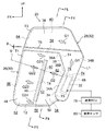
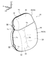
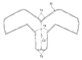
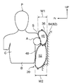
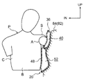
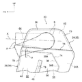
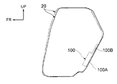
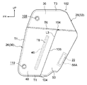
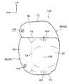
- FIG. 1 is a side view of a vehicle seat on which a vehicle side airbag device according to a first embodiment of the present invention is mounted, and is a view of a state in which the side airbag is inflated and deployed. It is an enlarged side view which expands and shows the side airbag. It is an expansion perspective view which expands and shows the side airbag.
- FIG. 3 is an enlarged cross-sectional view showing a cut surface along the line F4-F4 of FIG.
- FIG. 3 is an enlarged cross-sectional view showing a cut surface along the line F5-F5 of FIG. It is a plane expanded view which shows the base fabric of the main bag part with which the side airbag is equipped.
- FIG. 2 is an enlarged cross-sectional view showing a cut surface along the line F8-F8 in FIG.
- FIG. 2 is a cross-sectional view showing a cut surface along the line F9-F9 in FIG.
- FIG. 10 is a cross-sectional view corresponding to FIG. 9 illustrating a state in which the side airbag is compressed between the seated occupant and the door trim by the impact of the side collision. It is sectional drawing for demonstrating the condition at the time of the upper arm part of a seating passenger
- FIGS. 1-10 A vehicle side airbag device 10 according to a first embodiment of the present invention will be described with reference to FIGS.
- an arrow FR, an arrow UP, and an arrow IN that are appropriately described in each figure indicate the front direction (traveling direction), the upward direction, and the inner side in the vehicle width direction of the vehicle.
- the front-rear direction of the vehicle and the up-down direction of the vehicle are indicated unless otherwise specified.
- the side airbag device 10 includes a door-side side portion 14 ⁇ / b> A (a side portion on the side door 82 shown in FIGS. 9 and 10) of a seatback 14 in a vehicle seat 12. ).
- the seat back 14 is connected to the rear end portion of the seat cushion 16 so as to be tiltable, and a headrest 18 is connected to the upper end portion.
- the front-rear direction, the left-right direction (width direction), and the up-down direction of the vehicle seat 12 coincide with the front-rear direction, left-right direction (width direction), and up-down direction of the vehicle.
- an international unified side impact dummy (WorldSID) P is seated on the vehicle seat 12 instead of an actual occupant.
- the seating posture of this international unified side collision dummy P is determined by the side collision test method (ECE R95) currently used in Japan and Europe, or the side collision test method (FMVSS214) adopted in the United States. It is.
- the inclination angle (reclining angle) of the seat back 14 with respect to the seat cushion 16 is set at a reference setting position corresponding to the seating posture.
- the international unified side collision dummy P is referred to as “seat occupant P” for convenience of explanation.
- the side airbag device 10 includes a side airbag 20 and an inflator 22 as gas generating means for generating gas in the side airbag 20.
- the side airbag 20 is disposed inside the door side portion 14A in a state of being folded and unitized together with the inflator 22 and the like, and the seat occupant P, the vehicle body side portion and the vehicle body side portion are formed by the pressure of gas generated by the inflator 22.
- the seat back pad 24 (see FIG. 8) disposed on the door side portion 14A and a seat cover sewing portion (not shown) covering the seat back pad 24 are provided on the side airbag 20. It is configured to be cleaved by receiving expansion pressure.
- the front-back and up-down directions of the side airbag 20 described in the following description are directions in a state where the side airbag 20 is inflated and deployed, and substantially coincide with the front-back and up-down directions of the vehicle.
- the side airbag 20 includes a main bag portion 26 and a sub bag portion 28.
- a single base fabric 30 (see FIG. 6) formed by cutting out a nylon or polyester fabric material is folded in two along the fold line L1, and the peripheral portion is sewn. By sewing at T1 and T2, it is formed in a bag shape in which one end side (the upper end side in the inflated and deployed state) is opened.
- the sub-bag portion 28 has one base fabric 32 (see FIG. 7) made of the same fabric material as the base fabric 30 folded in two along the fold line L2, and the peripheral portion is sewn with sewing portions T3, T4, By sewing at T5, it is formed in a substantially inverted L-shaped bag shape.
- the sub-bag portion 28 includes an inner tube portion 34 that extends in the seat back height direction (substantially vertical direction) in an inflated and deployed state, and an upper end portion of the inner tube portion 34 from A shoulder bag portion (upper bag portion) 36 extending to the front side, and a bracing portion 38 that expands and deploys in a bracing manner between the inner tube portion 34 and the shoulder bag portion 36.
- the inside of the shoulder bag portion 36 is a shoulder chamber 40, and the lower side of the inner tube portion 34 is an inflator accommodating portion 34 ⁇ / b> A for accommodating the inflator 22.
- the upper side of the inner tube portion 34 is a gas introduction portion 34 ⁇ / b> B to the shoulder chamber 40.
- This gas introduction part 34B is formed such that the longitudinal dimension increases toward the upper end side by providing the bracing part 38, and the inside of the inflator accommodating part 34A and the shoulder chamber 40 via the gas introduction part 34B. And communicated with each other.
- the bracing portion 38 is configured such that the upper end 38A is positioned on the vehicle front side with respect to the lower end 38B in the inflated and deployed state of the side airbag 20.
- the inner tube portion 34 and the bracing portion 38 are inserted on the rear end side in the main bag portion 26, and the lower end portion of the shoulder bag portion 36 is sewn on the upper end edge of the main bag portion 26. Sewing is performed at T6.
- the main bag portion 26 and the sub bag portion are integrally coupled, and the upper end opening of the main bag portion 26 is closed by the sub bag portion 28.
- the inside of the main bag portion 26 and the inside of the sub bag portion 28 are partitioned by sewing portions T4 and T5 of the sub bag portion 28.
- a gas supply port (opening) 42 is formed in the vicinity of the central portion in the vertical direction of the inner tube portion 34, and the inside of the inner tube portion 34 and the main bag portion 26 (described later) through the gas supply port 42.
- the rear chamber 54) is in communication.
- the gas supply port 42 is formed by providing a non-sewn part between the sewing part T4 and the sewing part T5.
- a tether (strap: divider cloth) 46 is provided inside the main bag portion 26.
- the tether 46 is formed in a long rectangular shape, for example, by the same cloth material as the base fabrics 30 and 32, and as shown in FIGS. 5 and 8, one long side edge portion is formed at the sewing portion T7.
- One side portion 30A (see FIG. 6) of the fabric 30 is sewn, and the other long side edge portion is sewn to the other side portion 30B (see FIG. 6) of the base fabric 30 at the sewing portion T8.
- the tether 46 is provided so as to extend in the seat bag height direction (substantially up and down direction) when the side airbag 20 is inflated and deployed.
- the tether 46 causes the main bag portion 26 to be connected to the front bag portion 48 and the rear bag portion 48.
- the bag part 50 is partitioned.
- the front bag portion 48 is a front chamber 52
- the rear bag portion 50 is a rear chamber 54.
- the front chamber 52 and the rear chamber 54 are partitioned forward and backward by a tether 46.
- a lower communication portion (gap) 56 is formed between the lower end portion of the tether 46 and the lower end portion of the main bag portion 26, and the lower communication portion
- the front chamber 52 and the rear chamber 54 are communicated with each other via the portion 56.
- an upper communication portion (gap) 58 is formed between the upper end portion of the tether 46 and the shoulder bag portion 36, and the front chamber 52 and the rear chamber 54 communicate with each other via the upper communication portion 58.
- the tether 46 is formed with a plurality of (here, two) circular openings (vent holes) 60 and 62 arranged in the vertical direction (longitudinal direction), and the front chamber is formed through these openings 60 and 62. 52 and the rear chamber 54 communicate with each other.
- the upper opening 60 is provided so as to be positioned on the same straight line (virtual line) V as the gas supply port 42 described above in the inflated and deployed state of the side airbag 20.
- vent hole 64 that communicates the shoulder chamber 40 and the outside of the side airbag 20 is formed on the lower side of the front edge of the shoulder bag portion 36.
- the vent hole 64 is formed by providing a non-sewing part between the sewing part T3 and the sewing part T4.
- a vent hole (front chamber exhaust port) 66 that connects the front chamber 52 and the outside of the side airbag 20 is formed on the lower side of the front edge of the front bag portion 48.
- the vent hole 66 is formed by providing a non-sewn part between the sewing part T1 and the sewing part T2.
- the vent hole 66 is disposed at a position offset below the lower opening 62 formed in the tether 46 and offset above the lower communication portion 56 when the side airbag 20 is inflated and deployed.
- the inflator 22 is a so-called cylinder type inflator and is formed in a cylindrical shape.
- the inflator 22 is coaxially accommodated inside a diffuser 68 formed in a bottomed cylindrical shape, and is fixed to the diffuser 68 by caulking part of the diffuser 68.
- the inflator 22 and the diffuser 68 are accommodated in the above-described inflator accommodating portion 34 ⁇ / b> A in a state where the axial direction is along the height direction of the seat back 14 and the opening of the diffuser 68 faces upward. ing.
- a pair of upper and lower stud bolts 70 protrude from the outer peripheral portion of the diffuser 68 toward the inner side in the vehicle width direction. These stud bolts 70 penetrate the base fabrics 30 and 32 and the side frame 15A of the seat back frame 15, and a nut 72 is screwed to the tip side. Thereby, the diffuser 68 is fastened and fixed to the side frame 15 ⁇ / b> A together with the side airbag 20.
- Gas diffusers 74 and 76 are formed in the diffuser 68 at positions facing the upper end and the gas supply port 42, respectively. The gas outlet 76 facing the gas supply port 42 is formed so as to be disposed on the straight line V described above in a state where the side airbag 20 is inflated and deployed.
- a side collision ECU 78 mounted on the vehicle is electrically connected to the inflator 22 described above.
- a side collision sensor 80 for detecting a side collision is electrically connected to the side collision ECU 78.
- the side collision ECU 78 is configured to operate the inflator 22 when a side collision (inevitable) is detected based on a signal from the side collision sensor 80.
- a pre-crash sensor for predicting (predicting) a side collision is electrically connected to the side collision ECU 78
- the inflator is used when the side collision ECU 78 predicts a side collision based on a signal from the pre-crash sensor. 22 may be configured to be operated.
- gas ejected from a gas ejection hole (not shown) provided in the inflator 22 is ejected from the gas ejection ports 74 and 76 of the diffuser 68.
- the gas G1 ejected from the gas ejection port 74 of the diffuser 68 is supplied to the shoulder chamber 40 through the gas introduction part 34B of the inner tube part 34. Thereby, the shoulder bag part 36 expand
- the gas G2 ejected from the gas ejection port 76 of the diffuser 68 is supplied to the rear chamber 54 through the gas supply port 42 of the inner tube portion 34.
- the rear bag part 50 expand
- the gas G2 supplied to the rear chamber 54 is supplied to the front chamber 52 through upper and lower openings 60 and 62 formed in the upper communication portion 58, the lower communication portion 56 and the tether 46 (FIG. 2). (See arrows G21, G22, G23, G24).
- the front bag part 48 is inflated and deployed.
- the side airbag 20 in the inflated and deployed state will be described in detail.
- the side airbag 20 when the side airbag 20 is inflated and deployed, the side airbag 20 is interposed between the seated occupant P and the door trim 84 (vehicle body side portion) of the side door 82.
- the shoulder bag portion 36 is inflated and deployed so as to extend from the side of the shoulder portion S of the seated occupant P to the vehicle front side, and the front bag portion 48 and the rear bag are expanded.
- the portion 50 is inflated and deployed so as to be aligned in the front-rear direction below the shoulder bag portion 36.
- the shoulder bag portion 36 extends from the upper portion of the seat bag 14 (the upper portion when the seat bag 14 is divided into three equal parts into the upper portion, the middle portion in the vertical direction, and the lower portion) to the front of the vehicle.
- the front bag portion 48 is inflated and deployed on the front side of the chest C and the abdomen B of the seated occupant P
- the rear bag portion 50 is inflated on the side of the rear side of the chest C and the abdomen B of the seated occupant P. expand.
- the inner tube portion 34 is inflated and deployed so as to extend along the vehicle vertical direction on the rear side of the rear bag portion 50
- the bracing portion 38 includes a rear end side of the front bag portion 48 and an upper end side of the inner tube portion 34. It expands and develops in the form of a brace.
- the expansion thickness (dimension in the vehicle width direction: the same applies hereinafter) W1 of the shoulder bag portion 36 is set to be smaller than the expansion thickness W2 of the front bag portion 48.
- the expansion thickness W3 of the rear bag portion 50 is set to be larger than the expansion thickness W2 of the front bag portion 48. That is, the inflated thickness of the side airbag 20 in the inflated and deployed state is set to a relationship of W3> W2> W1.
- FIG. 10 shows a state in which the side airbag 20 is compressed between the seated occupant P and the door trim 84 due to the impact of the side collision.
- the dimensional relationship in the inflated thickness of the side airbag 20 is set by the vertical width dimension of the shoulder bag portion 36 in the unexpanded state and the sewing position of the tether 46 to the main back portion 26. Has been.
- the expansion thickness W1 of the shoulder bag portion 36 is set to be smaller than the expansion thickness W2 of the front bag portion 48, so that the vehicle width direction on the upper end side of the front bag portion 48 is shown in FIG.
- the upper arm portion pushing surface 86 is curved so that the inner side surface rises toward the outside in the vehicle width direction. In addition, you may make it the structure which inclines so that the upper arm part pushing surface 86 may rise as it goes to a vehicle width direction outer side.
- the side airbag 20 has a shoulder portion of the seated occupant P as seen from the vehicle width direction at the boundary between the shoulder bag portion 36 and the main bag portion 26, that is, the sewing portion T6 (see FIG. 2: not shown in FIG. 1). It is formed so as to be located below the center O of S and above the side U of the seated occupant P. Specifically, the position is aligned with the lower end of a core member (not shown) provided on the shoulder S of the seated occupant P, that is, the international unified side collision dummy P, in the vehicle width direction.
- the above-described sewing portion T6 is formed so as to incline forward with respect to the vehicle front-rear direction as shown in FIGS. 2 and 12 when the seat back 14 is located at the reference setting position described above.
- Yes. 2 indicates the inclination angle of the sewing portion T6 with respect to the vehicle longitudinal direction.
- the shoulder bag portion 36 is set such that the vertical width dimension in the unexpanded unfolded state becomes smaller toward the vehicle front side, and as shown in FIG. It expands and develops in a substantially truncated cone shape that slopes upward.
- the side airbag 20 has a boundary in the vehicle front-rear direction between the front bag portion 48 and the rear bag portion 50, that is, a tether 46 on the side surface of the chest C of the seated occupant P. It is formed so as to face the front-rear direction intermediate part (the front-rear direction center part or the vicinity of the front-rear direction center part).
- the inner side surface in the vehicle width direction of the side airbag 20 is recessed outward in the vehicle width direction in the plan view shown in FIG.
- the concave portion 90 is opposed to the front-rear direction intermediate portion (that is, the portion that protrudes most outward in the vehicle width direction) on the side surface of the chest C.
- the volume of the shoulder bag portion 36 is set to be sufficiently smaller than the volume of the main bag portion 26, and the gas ejected from the inflator 22 is preferentially supplied to the shoulder chamber 40.
- the internal pressure of the shoulder bag portion 36 in the inflated and deployed state is configured to be higher than the internal pressure of the main bag portion 26 (the internal pressures of the front bag portion 48 and the rear bag portion 50).
- the upper communication portion 58 is set to have a larger opening area in the vehicle front-rear direction view when the side airbag 20 is inflated and deployed than the lower communication portion 56.
- region 92 which is the part above the tether 46 in the main bag part 26 may increase, and the expansion
- the inflator 22 is operated by the side collision ECU 78. Then, the gas ejected from the inflator 22 is supplied into the side airbag 20, and the side airbag 20 is inflated and deployed between the seat occupant P and the door trim 84 of the side door 82.
- the side airbag 20 includes a shoulder bag portion 36 that extends from the side of the shoulder portion S of the seated occupant P to the vehicle front side in an inflated and deployed state, and a main bag that is positioned on the sides of the chest C and the abdominal portion B of the seated occupant P.
- the shoulder bag portion 36 is set to have a smaller expansion thickness (dimension in the vehicle width direction) than the main bag portion 26.
- the shoulder bag portion 36 is inflated and deployed so as to extend from the side of the shoulder portion S of the seated occupant P to the vehicle front side as described above. Therefore, for example, even when the side collision is an oblique side collision and the seat occupant P is inertially moved obliquely forward of the vehicle, the shoulder S of the seat occupant P is prevented from being detached from the shoulder bag portion 36. it can. This makes it possible to favorably restrain the shoulder S of the seated occupant P by the side airbag 20 regardless of the side collision, and to maintain the restraint of the shoulder S until the second half of the collision. .
- the main bag portion 26 is partitioned into a front bag portion 48 and a rear bag portion 50 that are aligned in the vehicle front-rear direction in the inflated and deployed state. Accordingly, the front side of the chest C and the abdomen B of the seated occupant P having relatively low resistance is restrained by the front bag part 48, and the rear side of the relatively highly resistant chest C and abdomen B is restrained by the rear bag part 50. Can do. Further, as described above, the shoulder portion S and the upper arm portion A having relatively high resistance can be restrained by the shoulder bag portion 36. In this manner, the body (upper body) of the seated occupant P can be appropriately restrained by the shoulder bag portion 36, the front bag portion 48, and the rear bag portion 50 that are set according to the level of resistance.
- the front bag portion 48 and the rear bag portion 50 can be constrained so as to cover the side surfaces of the chest C and the abdomen B of the seated occupant P from the front and back along the curve. Thereby, the positional relationship of the chest C and abdomen B and the side airbag 20 in the vehicle front-rear direction can be stabilized.
- the side airbag 20 has an inner side surface in the vehicle width direction near the boundary.
- a recess 90 is formed that is recessed outward in the vehicle width direction. Accordingly, the concave portion 90 faces the middle portion in the front-rear direction on the side surfaces of the chest C and the abdomen B (that is, the portion that protrudes most outward in the vehicle width direction), thereby reducing the load on the chest C and the abdomen B (such as the ribs). can do.
- the positional relationship in the vehicle front-rear direction of the chest C and the abdomen B and the side airbag 20 can be further stabilized. Can do.
- the side airbag 20 is In the inflated and deployed state, the inner side surface in the vehicle width direction of the side airbag 20 is recessed outward in the vehicle width direction near the boundary. Thereby, the upper arm pushing surface 86 can be largely curved so as to rise as it goes outward in the vehicle width direction. Moreover, in the inflated and deployed state of the side airbag 20, the boundary is located below the center of the shoulder S of the seated occupant P as viewed from the vehicle width direction and above the side U.
- the internal pressure of the shoulder bag portion 36 that restrains the relatively resistant shoulder S restrains the chest C and the abdomen B that are relatively resistant. It is comprised so that it may become higher than the internal pressure (respective internal pressure of the front bag part 48 and the rear bag part 50) of the main bag part 26.
- FIG. Accordingly, it is possible to effectively restrain the relatively resistant part while reducing the load on the part of the seated occupant P having relatively low resistance. As a result, the occupant restraint performance by the side airbag 20 can be improved.
- the size (inflated thickness) in the vehicle width direction of the side airbag 20 in the inflated and deployed state is “rear bag portion 50> front bag portion 48> shoulder bag portion 36: W3> W2> W1”.
- the restraint according to the load tolerance level in the body of the seated occupant P can be controlled not only by setting the internal pressure of the side airbag 20 but also by setting the expansion thickness. That is, while the rear bag portion 50 having a larger inflated thickness than the front bag portion 48 restrains the rear side of the chest C and the abdomen B that are relatively highly resistant, the chest C and the abdomen B that are relatively less resistant by the front bag portion 48.
- the front side can be restrained.
- crew restraint property by the side airbag 20 can be improved further.
- the inner side surface (upper arm pushing surface 86) in the vehicle width direction on the upper end side of the front bag portion 48 is directed outward in the vehicle width direction. It can be greatly curved to rise as it goes. As a result, it is possible to promote the behavior of pushing the upper arm portion A upward.
- the shoulder bag portion 36 and the front bag portion 48 are respectively formed with vent holes 64 and 66 for discharging the gas supplied to the outside.
- the internal pressure of the shoulder bag part 36 and the front bag part 48 can be easily adjusted independently by setting and changing the size of the vent holes 64 and 66 individually.
- the vent holes 64 and 66 are provided at the front edge portion of the side airbag 20 so as to be separated from each other in the vertical direction, it is possible to prevent the gas discharged from the vent holes 64 and 66 from concentrating on one place. As a result, the seated occupant P can be made less susceptible to high temperature gas.
- the inflator 22 is provided in the shoulder bag portion 36 and the inner tube portion 34 communicated with the rear bag portion 50, the gas generated by the inflator 22 is generated in the shoulder bag portion 36 and It can be smoothly supplied into the rear bag portion 50.
- the shoulder bag part 36 and the rear bag part 50 can be inflated and deployed at an early stage, and the shoulder part S, the chest part C, and the rear side of the abdominal part B having relatively high resistance can be restrained at an early stage.
- the inside of the front bag portion 48 and the inside of the rear bag portion 50 are communicated via the upper side communicating portion 58 and the lower side communicating portion 56, the gas supplied into the rear bag portion 50 is contained in the front bag portion 48. Can be supplied smoothly, and the expansion and expansion of the front bag portion 48 can be promoted.
- the upper communication portion 58 has a larger opening area in the vehicle front-rear direction view when the side airbag 20 is inflated and deployed than the lower communication portion 56.
- the upper communication portion 58 has a larger opening area in the vehicle front-rear direction view when the side airbag 20 is inflated and deployed than the lower communication portion 56.
- the vicinity of the armpit in the upper arm portion A of the seated occupant P can be restrained by the arm arm restraint region 92, and the push-up behavior of the upper arm portion A can be promoted.
- the gas generated by the inflator 22 is supplied into the rear bag portion 50 through the gas outlet 76 formed in the diffuser 68 and the gas supply port 42 formed in the inner tube portion. , And are supplied into the front bag portion 48 through openings 60 and 62 formed in the tether 46.
- the gas ejection port 76, the gas supply port 42 and the opening 60 are aligned on the straight line V in the inflated and deployed state of the side airbag 20, the gas generated by the inflator 22 is passed through the rear bag portion 50. Can be smoothly supplied into the front bag portion 48. Thereby, the expansion
- a vent hole 66 for discharging the gas in the front bag portion 48 to the outside is formed at the edge portion on the vehicle front side of the front bag portion 48 in the inflated and deployed state. , Formed at a position offset downward from the opening 62 formed in the tether 46. Accordingly, the gas supplied to the front bag portion 48 through the opening 62 formed in the tether 46 can be prevented from being discharged directly (linearly) from the vent hole 66 to the outside. It is possible to prevent the internal pressure of the front bag portion 48 from becoming too high while improving the initial deployment performance.
- the shoulder bag 36 extending from the upper end portion of the inner tube portion 34 to the vehicle front side in the inflated and deployed state of the side airbag 20 receives gas from the inflator 22 provided in the inner tube portion 34. Supplied preferentially. Thereby, when the internal pressure of the shoulder bag portion 36 is higher than the internal pressure of the front bag portion 48, the front portion side of the shoulder bag portion 36 may be displaced downward so as to push the front bag portion 48 downward. . As a result, when the connecting portion between the shoulder bag portion 36 and the inner tube portion 34 is bent, the behavior of the side airbag 20 bows as shown by the solid line in FIG. By swinging to the side (see arrow B in FIG.
- the bracing-like bracing portion 38 is inflated and deployed between the shoulder bag portion 36 and the inner tube portion, and therefore the bending of the connecting portion is prevented or effectively suppressed by the bracing portion 38. can do. Thereby, the deployment position of the side airbag 20 can be stabilized.
- the shoulder bag portion 36 is set so that the vertical width dimension in the unexpanded unfolded state becomes smaller toward the vehicle front side, so that the shoulder bag portion 36 becomes thinner toward the vehicle front side. Inflates and expands. Thereby, the expansion
- the sewing portion T6 set at the upper end of the main bag portion 26 is in front of the vehicle longitudinal direction. Tilt up.
- the point of action of the push-up force F acting on the upper arm portion A of the seated occupant P due to sliding contact with the vehicle lateral direction inner side surface (upper arm pushing surface 86) on the upper end side of the main bag portion 26 can be further increased.
- the shoulder bag portion 36 is inflated and deployed in a substantially truncated cone shape that becomes thinner toward the front end side of the side airbag 20, and the axis X (see FIG. 12) of the shoulder bag portion 36 rises forward with respect to the vehicle longitudinal direction. Inclined to. As a result, the curved surface on the upper side of the inner side surface in the vehicle width direction of the shoulder bag portion 36 is inclined forwardly along the axis X. For this reason, when the seated occupant P is inertially moved obliquely forward of the vehicle due to the impact of the oblique side collision, the shoulder S of the seated occupant P is in sliding contact with the curved surface of the shoulder bag portion 36, so that the shoulder S is It will be pushed up. Thereby, pushing up of the upper arm part A can be promoted.
- the upper end (sewing part T6) of the main bag part 26 rises forward with respect to the vehicle front-rear direction with the seat back 14 positioned at the reference setting position and the side airbag 20 inflated and deployed.
- the structure is inclined, the present invention is not limited to this.
- the upper end of the main bag portion 26 may be configured along the vehicle front-rear direction (extend horizontally).
- the shoulder bag portion 36 may have a configuration in which the vertical width dimension is set to be constant.
- the bracing-like bracing portion 38 is inflated and deployed between the shoulder bag portion 36 and the inner tube portion 34.
- the present invention is not limited to this, and the bracing portion 38 is omitted. It may be configured as described above.
- the gas supply port 42 of the inner tube portion 34, the gas outlet 76 of the diffuser 68, and the opening 60 of the tether 46 are on the same straight line V in the inflated and deployed state of the side airbag 20.
- the present invention is not limited to this, and the positions of the gas supply port of the inner tube portion, the gas outlet of the diffuser, and the opening of the tether can be appropriately changed. The same applies to the position of the vent hole.
- the upper communication portion 58 and the lower communication portion 56 are provided above and below the tether 46.
- the present invention is not limited to this, and the upper communication portion and the lower communication portion are not limited thereto. One or both may be omitted.
- deployment state of the side airbag 20 is not restricted to the structure of the said 1st Embodiment, It can change suitably. it can.
- the side airbag 20 was set as the structure provided with the inner tube part 34, this invention is not limited to this, A rectifier cloth, a diffuser, etc. are used instead of an inner tube part, and an inflator is used. You may make it the structure which distributes gas in a shoulder bag part and a main bag part.
- vent holes 64 and 66 are formed in the shoulder bag portion 36 and the main bag portion 26, respectively.
- the present invention is not limited thereto, and the vent holes 64 and 66 are Any one or both may be omitted.
- the internal pressure of the shoulder bag portion 36 is higher than the internal pressure of the main bag portion 26 in the inflated and deployed state of the side airbag 20, but the present invention is not limited to this.
- the internal pressure of the bag portion can be appropriately changed.
- the internal pressures of the bag portions may be equal.
- the expansion thickness W3 of the rear bag part 50 was larger than the expansion thickness W2 of the front bag part 48, this invention is not limited to this, The expansion thickness of a front bag part is back. You may make it the structure larger than the expansion
- the front-rear direction boundary (tether 46) between the front bag portion 48 and the rear bag portion 50 is the front-rear direction of the chest C of the seated occupant P.
- the present invention is not limited to this, and the position of the boundary can be changed as appropriate. The same applies to the position of the boundary between the shoulder bag portion 36 and the main bag portion 26.
- main bag part 26 was set as the structure partitioned off into the front bag part 48 and the rear bag part 50, this invention is not restricted to this, The inside of the main bag part 26 is partitioned back and forth. You may make it the structure which is not.
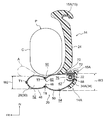
- FIG. 14 is a side view showing an inflated and deployed state of the side airbag 20 which is a constituent member of the vehicle side airbag device according to the second embodiment of the present invention.
- the configuration of the diffuser 100 is different from the diffuser 68 according to the first embodiment.
- the diffuser 100 includes a main body portion 100A having the same configuration as the diffuser 68, and an extension portion 100B (support portion) extending upward from the upper end of the main body portion 100A along the rear end edge of the inner tube portion 34.
- the upper end of the extension part 100B is located above the lower end 38B of the brace part 38 and below the upper end 38A of the brace part 38.
- the bracing behavior (see FIG. 13) of the side airbag 20 can be prevented or effectively suppressed by the brace portion 38 provided in the subbag portion 28.
- the rear end edge of the inner tube portion 34 is supported from the vehicle front side above the lower end 38B of the bracing portion 38 by the extension portion 100B provided in the diffuser 100 (see FIG. 15). .
- the deployment position of the side airbag 20 can be more stably stabilized.
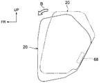
- FIG. 16 is a side view showing a non-inflated deployed state of the side airbag 102 which is a constituent member of the vehicle side airbag device according to the third embodiment of the present invention.
- the side airbag 102 is different from the side airbag 20 according to the first embodiment in that a pair of upper and lower tack portions (folded portion: pleat portion) 104 is provided on the rear bag portion 50.
- These tack portions 104 are formed by folding a part of a surface of the base fabric 30 constituting the rear bag portion 50 that faces in the vehicle width direction in the inflated and deployed state of the rear bag portion 50 along a fold line L3 along the vertical direction.
- the upper and lower end portions of the folded portion are formed by sewing at the sewing portions T1 and T6.
- an extra length portion 106 is formed between the pair of tack portions 104.
- the pair of tack portions 104 and the extra length portion 106 are formed on both side surfaces in the vehicle width direction of the rear bag portion 50 in the inflated and deployed state, but are formed only on one side surface in the vehicle width direction. It may be configured.
- the vent holes 64 and 66 according to the first embodiment are omitted.
- the shoulder bag portion 36 is formed with a circular vent hole 108 on the front end side of the surface facing the vehicle width direction outside in the inflated and deployed state.
- a circular vent hole 110 is formed in the front bag portion 48 on the front end side and the lower end side of the surface facing the vehicle width direction outside in the inflated and deployed state.
- illustration of the inner tube portion 34 and the bracing portion 38 is omitted, but the configuration other than the above is the same as that of the first embodiment.
- the extra length part 106 between the pair of tack parts 104 extends as shown in FIG. (Expanded thickness) increases.
- the expansion thickness of the rear bag portion 50 is increased by the tack portion 104, the size of the rear bag portion 50 in the vehicle front-rear direction in the inflated and deployed state, There is no need to change the position of the boundary between the portion 48 and the rear bag portion 50. Thereby, the freedom degree of design of the side airbag 102 can be improved.
- the shoulder bag portion 36 and the front bag portion 48 are formed with vent holes 108 and 110 on the surfaces facing the outer side in the vehicle width direction in the inflated and deployed state. The seated occupant P is less likely to be affected by the high temperature.
Abstract
Description
本発明の第1実施形態に係る車両用サイドエアバッグ装置10について、図1~図12に基づいて説明する。なお、各図に適宜記す矢印FR、矢印UP、矢印INは、車両の前方向(進行方向)、上方向、車幅方向の内側をそれぞれ示している。以下、単に前後、上下の方向を用いて説明する場合は、特に断りのない限り、車両前後方向の前後、車両上下方向の上下を示すものとする。 <First Embodiment>
A vehicle
図1に示されるように、本実施形態に係るサイドエアバッグ装置10は、車両用シート12におけるシートバック14のドア側サイド部14A(図9及び図10に示されるサイドドア82側の側部)に搭載されている。このシートバック14は、シートクッション16の後端部に傾倒可能に連結されており、上端部にはヘッドレスト18が連結されている。 (Constitution)
As shown in FIG. 1, the
次に、本実施形態の作用及び効果について説明する。 (Function and effect)
Next, the operation and effect of this embodiment will be described.
上記第1実施形態では、シートバック14が基準設定位置に位置し且つサイドエアバッグ20が膨張展開した状態で、メインバッグ部26の上端(縫製部T6)が車両前後方向に対して前上がりに傾斜する構成にしたが、本発明はこれに限るものではない。例えば、メインバッグ部26の上端が車両前後方向に沿う(水平に延びる)構成にしてもよい。 (Supplementary explanation of the first embodiment)
In the first embodiment, the upper end (sewing part T6) of the
図14には、本発明の第2の実施形態に係る車両用サイドエアバッグ装置の構成部材であるサイドエアバッグ20の膨張展開状態が側面図にて示されている。このサイドエアバッグ装置では、ディフューザ100の構成が前記第1実施形態に係るディフューザ68とは異なる。このディフューザ100は、ディフューザ68と同じ構成とされた本体部100Aと、該本体部100Aの上端からインナチューブ部34の後端縁に沿って上方側へ延びる延長部100B(支持部)とによって構成されている。延長部100Bの上端は、筋交い部38の下端38Bよりも上方側で且つ筋交い部38の上端38Aよりも下方側に位置している。 <Second Embodiment>
FIG. 14 is a side view showing an inflated and deployed state of the
図16には、本発明の第3の実施形態に係る車両用サイドエアバッグ装置の構成部材であるサイドエアバッグ102の非膨張での展開状態が側面図にて示されている。このサイドエアバッグ102は、後バッグ部50に上下一対のタック部(折り返し部:ひだ部)104が設けられている点で前記第1実施形態に係るサイドエアバッグ20とは異なる。これらのタック部104は、後バッグ部50を構成する基布30のうち、後バッグ部50の膨張展開状態で車幅方向を向く面の一部が上下方向に沿った折れ線L3に沿って折られると共に、当該折られた部分の上下両端部が縫製部T1、T6において縫製されることにより形成されている。これにより、一対のタック部104の間には余長部106が形成されている。なお、本実施形態では、一対のタック部104及び余長部106が、膨張展開状態の後バッグ部50における車幅方向両側面に形成されているが、車幅方向片側面のみに形成された構成にしてもよい。 <Third Embodiment>
FIG. 16 is a side view showing a non-inflated deployed state of the
Claims (16)
- 車両用シートに設けられ、車両の側面衝突が検知又は予知された場合に作動されてガスを発生させるインフレータと、
前記車両用シートのシートバックの側部に設けられ、前記インフレータが発生させるガスが内部に供給されることにより着座乗員と車体側部との間に膨張展開すると共に、膨張展開状態で着座乗員の肩部の側方から車両前方へ延びる肩バッグ部と着座乗員の胸部及び腹部の側方に位置するメインバッグ部とに区画され、前記肩バッグ部が前記メインバッグ部よりも車幅方向の寸法を小さく設定されることにより、前記メインバッグ部の上端側における車幅方向内側面が車幅方向外側へ向かうに従い上昇するように傾斜又は湾曲するサイドエアバッグと、
を備えた車両用サイドエアバッグ装置。 An inflator provided in a vehicle seat and activated when a side collision of the vehicle is detected or predicted, and generates gas;
Provided inside the seat back of the vehicle seat, the gas generated by the inflator is inflated and deployed between the seat occupant and the vehicle body side, and the seat occupant is inflated and deployed. A shoulder bag portion extending from the side of the shoulder portion toward the front of the vehicle and a main bag portion positioned on the side of the chest and abdomen of the seated occupant, the shoulder bag portion being a dimension in the vehicle width direction than the main bag portion. A side airbag that is inclined or curved so that the inner side surface in the vehicle width direction on the upper end side of the main bag portion rises toward the outer side in the vehicle width direction,
Side airbag device for vehicles provided with. - 前記メインバッグ部は、前記膨張展開状態で車両前後方向に並ぶ前バッグ部と後バッグ部とに区画されている請求項1に記載の車両用サイドエアバッグ装置。 The vehicle side airbag device according to claim 1, wherein the main bag portion is partitioned into a front bag portion and a rear bag portion arranged in the vehicle longitudinal direction in the inflated and deployed state.
- 前記肩バッグ部と前記メインバッグ部とが前記膨張展開状態で車両前後方向に沿って延びるテザー又は縫製部によって区画されると共に、
前記膨張展開状態における前記肩バッグ部と前記メインバッグ部との境界が、車幅方向から見た着座乗員の肩部の中心よりも下方側で且つ着座乗員の脇部よりも上方側に位置するように形成されている請求項2に記載の車両用サイドエアバッグ装置。 The shoulder bag portion and the main bag portion are partitioned by a tether or a sewing portion extending along the vehicle front-rear direction in the inflated and deployed state,
The boundary between the shoulder bag portion and the main bag portion in the inflated and deployed state is located below the center of the shoulder of the seated occupant as viewed from the vehicle width direction and above the side of the seated occupant. The vehicle side airbag device according to claim 2, which is formed as described above. - 前記前バッグ部と前記後バッグ部とが前記膨張展開状態で車両上下方向に沿って延びるテザー又は縫製部によって区画されると共に、
前記膨張展開状態における前記前バッグ部と前記後バッグ部との境界が、着座乗員の胸部の前後方向中間部と対向するよう形成されている請求項2に記載の車両用サイドエアバッグ装置。 The front bag portion and the rear bag portion are partitioned by a tether or a sewing portion extending along the vehicle vertical direction in the inflated and deployed state,
The vehicle side airbag device according to claim 2, wherein a boundary between the front bag portion and the rear bag portion in the inflated and deployed state is formed so as to face a front-rear direction intermediate portion of a chest of a seated occupant. - 前記後バッグ部は、前記前バッグ部よりも前記膨張展開状態における車幅方向の寸法が大きい請求項2又は請求項4に記載の車両用サイドエアバッグ装置。 5. The vehicle side airbag device according to claim 2, wherein the rear bag portion has a larger dimension in the vehicle width direction in the inflated and deployed state than the front bag portion.
- 前記サイドエアバッグは、前記膨張展開状態において、前記肩バッグ部の内圧が前記メインバッグ部の内圧よりも高くなるように構成されている請求項1~請求項5の何れか1項に記載の車両用サイドエアバッグ装置。 The side airbag according to any one of claims 1 to 5, wherein in the inflated and deployed state, an internal pressure of the shoulder bag portion is higher than an internal pressure of the main bag portion. Vehicle side airbag device.
- 前記肩バッグ部及び前記メインバッグ部には、内部に供給されたガスを外部に排出するためのベントホールが各々に形成されている請求項1~請求項6の何れか1項に記載の車両用サイドエアバッグ装置。 The vehicle according to any one of claims 1 to 6, wherein the shoulder bag portion and the main bag portion are each formed with a vent hole for discharging the gas supplied to the outside. Side airbag device.
- 前記サイドエアバッグは、前記膨張展開状態で前記後バッグ部の車両後方側に位置するインナチューブ部を有し、該インナチューブ部内に前記インフレータが設けられ、該インナチューブ部の上部が前記肩バッグ部内へのガス導入部とされ、該インナチューブ部の上下方向中間部に前記後バッグ部内へのガス供給口が形成されると共に、前記前バッグ部内と前記後バッグ部内とが両者の上端側及び下端側で連通されている請求項2に記載の車両用サイドエアバッグ装置。 The side airbag has an inner tube portion located on the vehicle rear side of the rear bag portion in the inflated and deployed state, the inflator is provided in the inner tube portion, and an upper portion of the inner tube portion is the shoulder bag A gas supply port into the rear bag portion is formed in the middle portion in the vertical direction of the inner tube portion, and the inside of the front bag portion and the inside of the rear bag portion are the upper end side of both and The side airbag device for a vehicle according to claim 2, wherein the side airbag device is communicated at a lower end side.
- 前記前バッグ部と前記後バッグ部とが前記膨張展開状態で車両上下方向に沿って延びるテザーによって区画されており、
前記テザーの上端部と前記肩バッグ部との間には、前記前バッグ部の上端側と前記後バッグ部の上端側とを連通させた上側連通部が設けられ、前記テザーの下端部と前記メインバッグ部の下端部との間には、前記前バッグ部の下端側と前記後バッグ部の下端側とを連通させた下側連通部が設けられると共に、
前記上側連通部は、前記下側連通部よりも前記膨張展開状態での車両前後方向視における開口面積が大きく設定されている請求項8に記載の車両用サイドエアバッグ装置。 The front bag portion and the rear bag portion are partitioned by a tether extending in the vehicle vertical direction in the inflated and deployed state;
Between the upper end portion of the tether and the shoulder bag portion, there is provided an upper communication portion that connects the upper end side of the front bag portion and the upper end side of the rear bag portion, and the lower end portion of the tether and the Between the lower end portion of the main bag portion is provided with a lower communication portion that communicates the lower end side of the front bag portion and the lower end side of the rear bag portion,
9. The vehicle side airbag device according to claim 8, wherein the upper communication portion has a larger opening area when viewed in the vehicle front-rear direction in the inflated and deployed state than the lower communication portion. - 前記前バッグ部と前記後バッグ部とが前記膨張展開状態で車両上下方向に沿って延びるテザーによって区画されており、
前記インフレータは、前記インナチューブ部内に設けられたディフューザ内に収容されており、前記ガス供給口と前記ディフューザに形成されたガス噴出口と前記テザーに形成された開口とが、前記膨張展開状態で同一直線上に並ぶと共に、
前記膨張展開状態の前記前バッグ部における車両前方側の端縁部には、前記開口よりも下方にオフセットした位置に、前記前バッグ部内のガスを外部に排出するためのベントホールが形成されている請求項8又は請求項9に記載の車両用サイドエアバッグ装置。 The front bag portion and the rear bag portion are partitioned by a tether extending in the vehicle vertical direction in the inflated and deployed state;
The inflator is accommodated in a diffuser provided in the inner tube portion, and the gas supply port, a gas jet port formed in the diffuser, and an opening formed in the tether are in the expanded and deployed state. Along the same line,
A vent hole for discharging the gas in the front bag portion to the outside is formed at an end edge portion of the front bag portion of the front bag portion in the inflated and deployed state at a position offset downward from the opening. The vehicle side airbag device according to claim 8 or 9. - 前記膨張展開状態では、車両上下方向に沿って延びる前記インナチューブ部の上端部から前記肩バッグ部が車両前方側へ延びると共に、前記肩バッグ部と前記インナチューブ部との間に筋交い状の筋交い部が膨張展開する請求項8~請求項10の何れか1項に記載の車両用サイドエアバッグ装置。 In the inflated and deployed state, the shoulder bag portion extends from the upper end portion of the inner tube portion extending along the vehicle vertical direction to the vehicle front side, and a brace-like bracing is provided between the shoulder bag portion and the inner tube portion. The vehicle side airbag device according to any one of claims 8 to 10, wherein the portion is inflated and deployed.
- 前記ディフューザは、前記シートバックが備えるシートバックフレームに固定されると共に、前記筋交い部の下端よりも上方側で前記インナチューブ部の後端縁を支持する支持部を有する請求項11に記載の車両用サイドエアバッグ装置。 The vehicle according to claim 11, wherein the diffuser includes a support portion that is fixed to a seat back frame included in the seat back and supports a rear end edge of the inner tube portion above a lower end of the bracing portion. Side airbag device.
- 前記後バッグ部には、前記膨張展開状態において車幅方向を向く面の上下両端側が車両前後方向に折り返されて縫製されることにより上下一対のタック部が形成されている請求項2に記載の車両用サイドエアバッグ装置。 The pair of upper and lower tack portions according to claim 2, wherein upper and lower ends of a surface facing the vehicle width direction in the inflated and deployed state are folded and sewn in the vehicle front-rear direction in the rear bag portion. Vehicle side airbag device.
- 前記肩バッグ部は、非膨張での展開状態における上下幅寸法が車両前方側へ向かうほど小さくなるように設定されている請求項1~請求項13の何れか1項に記載の車両用サイドエアバッグ装置。 The vehicle side air according to any one of claims 1 to 13, wherein the shoulder bag portion is set such that a vertical width dimension in a non-inflated deployed state becomes smaller toward a vehicle front side. Bag device.
- 前記サイドエアバッグは、前記シートバックが基準設定位置に位置し且つ前記サイドエアバッグが膨張展開した状態で、前記メインバック部の上端が車両前後方向に対して前上がりに傾斜するように形成されている請求項1~請求項14の何れか1項に記載の車両用サイドエアバッグ装置。 The side airbag is formed such that the upper end of the main back portion is inclined forwardly with respect to the vehicle front-rear direction in a state where the seat back is located at a reference setting position and the side airbag is inflated and deployed. The vehicle side airbag device according to any one of claims 1 to 14.
- 車両用シートに設けられ、車両の側面衝突が検知又は予知された場合に作動されてガスを発生させるインフレータと、
前記車両用シートのシートバックにおける車幅方向外側の側部に設けられ、前記インフレータが発生させるガスが内部に供給されることにより前記シートバックの前方側へ膨張展開すると共に、膨張展開状態で前記シートバックの上部の車両前方へ延びる肩バッグ部と該肩バッグ部の下側に位置するメインバッグ部とに区画され、前記肩バッグ部が前記メインバッグ部よりも車幅方向の寸法を小さく設定されることにより、前記メインバッグ部の上端側における車幅方向内側面が車幅方向外側へ向かうに従い上昇するように傾斜又は湾曲するサイドエアバッグと、
を備えた車両用サイドエアバッグ装置。 An inflator provided in a vehicle seat and activated when a side collision of the vehicle is detected or predicted, and generates gas;
The vehicle seat is provided at a side portion on the vehicle width direction outer side of the seat back, and the gas generated by the inflator is inflated and deployed to the front side of the seat back by being supplied to the inside. The upper portion of the seat back is divided into a shoulder bag portion extending forward of the vehicle and a main bag portion located below the shoulder bag portion, and the shoulder bag portion is set to have a smaller size in the vehicle width direction than the main bag portion. A side airbag that is inclined or curved so that the inner side surface in the vehicle width direction on the upper end side of the main bag portion rises toward the outer side in the vehicle width direction,
Side airbag device for vehicles provided with.
Priority Applications (5)
| Application Number | Priority Date | Filing Date | Title |
|---|---|---|---|
| PCT/JP2012/064570 WO2013183130A1 (en) | 2012-06-06 | 2012-06-06 | Side airbag device for vehicle |
| JP2014519751A JP5831634B2 (en) | 2012-06-06 | 2012-06-06 | Side airbag device for vehicle |
| CN201280073789.2A CN104349945B (en) | 2012-06-06 | 2012-06-06 | Side air bag device for vehicle |
| EP12878315.6A EP2860070B1 (en) | 2012-06-06 | 2012-06-06 | Side airbag device for vehicle |
| US14/405,029 US9254811B2 (en) | 2012-06-06 | 2012-06-06 | Vehicle side-airbag device |
Applications Claiming Priority (1)
| Application Number | Priority Date | Filing Date | Title |
|---|---|---|---|
| PCT/JP2012/064570 WO2013183130A1 (en) | 2012-06-06 | 2012-06-06 | Side airbag device for vehicle |
Publications (1)
| Publication Number | Publication Date |
|---|---|
| WO2013183130A1 true WO2013183130A1 (en) | 2013-12-12 |
Family
ID=49711547
Family Applications (1)
| Application Number | Title | Priority Date | Filing Date |
|---|---|---|---|
| PCT/JP2012/064570 WO2013183130A1 (en) | 2012-06-06 | 2012-06-06 | Side airbag device for vehicle |
Country Status (5)
| Country | Link |
|---|---|
| US (1) | US9254811B2 (en) |
| EP (1) | EP2860070B1 (en) |
| JP (1) | JP5831634B2 (en) |
| CN (1) | CN104349945B (en) |
| WO (1) | WO2013183130A1 (en) |
Cited By (13)
| Publication number | Priority date | Publication date | Assignee | Title |
|---|---|---|---|---|
| US8783712B2 (en) | 2012-08-02 | 2014-07-22 | Toyota Jidosha Kabushiki Kaisha | Side airbag device for vehicle |
| JP2016011034A (en) * | 2014-06-27 | 2016-01-21 | 豊田合成株式会社 | Side airbag device |
| US9296356B2 (en) | 2012-07-19 | 2016-03-29 | Toyota Jidosha Kabushiki Kaisha | Vehicle side air bag device |
| JP2016078681A (en) * | 2014-10-17 | 2016-05-16 | 三菱自動車工業株式会社 | Side airbag device |
| US9399440B2 (en) | 2012-09-04 | 2016-07-26 | Toyota Technical Development Corporation | Vehicle side airbag device and side air bag manufacturing method |
| EP3127758A1 (en) * | 2015-08-07 | 2017-02-08 | Toyoda Gosei Co., Ltd. | Far-side airbag apparatus for deployment between adjacent vehicle seats |
| US9566934B2 (en) | 2014-10-09 | 2017-02-14 | Toyota Jidosha Kabushiki Kaisha | Vehicle side airbag device and manufacturing method of a side airbag |
| JPWO2016152245A1 (en) * | 2015-03-23 | 2017-10-19 | オートリブ ディベロップメント エービー | Airbag device |
| JPWO2016158022A1 (en) * | 2015-03-30 | 2018-02-08 | オートリブ ディベロップメント エービー | Side airbag device for vehicle |
| US10053044B2 (en) | 2015-08-07 | 2018-08-21 | Toyoda Gosei Co., Ltd. | Far-side airbag apparatus |
| JP2021054390A (en) * | 2019-09-30 | 2021-04-08 | 豊田合成株式会社 | Side airbag device |
| JP2021079909A (en) * | 2019-11-22 | 2021-05-27 | Joyson Safety Systems Japan株式会社 | Side airbag and side airbag device |
| US11214222B2 (en) * | 2020-01-22 | 2022-01-04 | ZF Passive Safety Systems US Inc. | Occupant restraint system |
Families Citing this family (23)
| Publication number | Priority date | Publication date | Assignee | Title |
|---|---|---|---|---|
| DE102013015141B4 (en) * | 2013-09-13 | 2017-08-10 | Trw Automotive Gmbh | Method for protecting a vehicle occupant and gas bag |
| JP5804214B2 (en) * | 2013-09-27 | 2015-11-04 | トヨタ自動車株式会社 | Side airbag device for vehicle and vehicle seat |
| JP6229593B2 (en) * | 2014-05-28 | 2017-11-15 | 豊田合成株式会社 | Side airbag device |
| JP6179469B2 (en) * | 2014-06-23 | 2017-08-16 | トヨタ自動車株式会社 | Far side airbag device |
| US9505369B2 (en) * | 2014-09-12 | 2016-11-29 | Toyoda Gosei Co., Ltd. | Side airbag apparatus |
| JP6102880B2 (en) * | 2014-10-07 | 2017-03-29 | トヨタ自動車株式会社 | Far side airbag device |
| JP6149840B2 (en) * | 2014-10-21 | 2017-06-21 | トヨタ自動車株式会社 | Far-side airbag device for vehicles |
| JP6225877B2 (en) * | 2014-10-22 | 2017-11-08 | トヨタ自動車株式会社 | Side airbag device for vehicle |
| JP6131935B2 (en) * | 2014-12-03 | 2017-05-24 | トヨタ自動車株式会社 | Far-side airbag device for vehicles |
| CN110509884B (en) * | 2015-03-06 | 2022-08-19 | 奥托立夫开发公司 | Airbag device |
| WO2017199850A1 (en) * | 2016-05-20 | 2017-11-23 | オートリブ ディベロップメント エービー | Side airbag device |
| US9682681B1 (en) * | 2016-05-31 | 2017-06-20 | Ford Global Technologies, Llc | Adaptive side torso airbag |
| JP6561942B2 (en) * | 2016-08-22 | 2019-08-21 | トヨタ自動車株式会社 | Vehicle seat with side airbag device |
| JP6852154B2 (en) * | 2017-05-17 | 2021-03-31 | オートリブ ディベロップメント エービー | Side airbag device |
| WO2018211894A1 (en) * | 2017-05-19 | 2018-11-22 | オートリブ ディベロップメント エービー | Side air bag device |
| EP3960553B1 (en) * | 2018-01-11 | 2023-07-19 | Autoliv Development AB | Occupant protection apparatus |
| DE102018101395A1 (en) * | 2018-01-23 | 2019-07-25 | Trw Automotive Gmbh | Side airbag and vehicle occupant restraint system |
| JP6933773B2 (en) * | 2018-04-05 | 2021-09-08 | オートリブ ディベロップメント エービー | Side airbag device and vehicle seat equipped with it |
| CN109591753B (en) * | 2018-11-30 | 2023-05-02 | 硅湖职业技术学院 | Active child safety airbag drawstring control device and control method thereof |
| US10926735B2 (en) * | 2019-04-02 | 2021-02-23 | Ford Global Technologies, Llc | Vehicle seat side airbag |
| US11383670B2 (en) * | 2019-09-30 | 2022-07-12 | Toyoda Gosei Co., Ltd. | Side airbag apparatus |
| JP7263648B2 (en) * | 2020-03-06 | 2023-04-25 | 豊田合成株式会社 | side airbag device |
| JP7380499B2 (en) * | 2020-09-29 | 2023-11-15 | トヨタ自動車株式会社 | Vehicle occupant protection device |
Citations (8)
| Publication number | Priority date | Publication date | Assignee | Title |
|---|---|---|---|---|
| JP2004217184A (en) * | 2003-01-17 | 2004-08-05 | Toyoda Gosei Co Ltd | Airbag device for side collision |
| JP2005186891A (en) * | 2003-12-26 | 2005-07-14 | Fuji Heavy Ind Ltd | Side airbag device for vehicle |
| JP2007520390A (en) * | 2004-02-06 | 2007-07-26 | オートリブ ディベロップメント アクティエボラーグ | Airbags built into automobiles |
| JP2010132072A (en) | 2008-12-03 | 2010-06-17 | Toyota Motor Corp | Side airbag device for vehicle |
| JP2011020502A (en) * | 2009-07-14 | 2011-02-03 | Toyoda Gosei Co Ltd | Side air bag device |
| WO2011087026A1 (en) * | 2010-01-12 | 2011-07-21 | 三菱自動車工業株式会社 | Side airbag |
| WO2011132316A1 (en) * | 2010-04-23 | 2011-10-27 | トヨタ自動車株式会社 | Vehicle side airbag device |
| JP2011240807A (en) * | 2010-05-18 | 2011-12-01 | Nippon Plast Co Ltd | Side airbag device for automobile |
Family Cites Families (13)
| Publication number | Priority date | Publication date | Assignee | Title |
|---|---|---|---|---|
| JP2962224B2 (en) * | 1996-04-08 | 1999-10-12 | 三菱自動車工業株式会社 | Airbag for side impact |
| JP2000280853A (en) | 1999-03-30 | 2000-10-10 | Toyota Central Res & Dev Lab Inc | Air bag device for side collision |
| JP3891066B2 (en) | 2002-07-30 | 2007-03-07 | 豊田合成株式会社 | Side airbag device |
| US20030168836A1 (en) | 2002-03-11 | 2003-09-11 | Eiji Sato | Side airbag apparatus |
| CN100349767C (en) * | 2003-01-20 | 2007-11-21 | 丰田自动车株式会社 | Vehicle occupant production device |
| US7819419B2 (en) * | 2003-01-20 | 2010-10-26 | Toyota Jidosha Kabushiki Kaisha | Occupant protection device |
| JP4292894B2 (en) * | 2003-06-30 | 2009-07-08 | 豊田合成株式会社 | Side airbag device |
| CN100410109C (en) * | 2004-12-24 | 2008-08-13 | 丰田合成株式会社 | Method of folding airbag, airbag device and airbag thereof |
| JP5232422B2 (en) * | 2006-11-07 | 2013-07-10 | タカタ株式会社 | Side impact airbag, side impact airbag device, vehicle seat |
| JP5060332B2 (en) | 2008-02-14 | 2012-10-31 | 京セラドキュメントソリューションズ株式会社 | Paper feeding device and image forming apparatus having the same |
| US8696021B2 (en) * | 2009-12-21 | 2014-04-15 | Toyota Jidosha Kabushiki Kaisha | Side airbag device and method of sewing side airbag |
| EP2441627B1 (en) * | 2010-10-18 | 2014-07-16 | Autoliv Development AB | An airbag arrangement for a motor vehicle |
| JP5382199B2 (en) * | 2010-11-17 | 2014-01-08 | トヨタ自動車株式会社 | Side airbag device for vehicle |
-
2012
- 2012-06-06 JP JP2014519751A patent/JP5831634B2/en active Active
- 2012-06-06 CN CN201280073789.2A patent/CN104349945B/en not_active Expired - Fee Related
- 2012-06-06 EP EP12878315.6A patent/EP2860070B1/en not_active Not-in-force
- 2012-06-06 WO PCT/JP2012/064570 patent/WO2013183130A1/en active Application Filing
- 2012-06-06 US US14/405,029 patent/US9254811B2/en not_active Expired - Fee Related
Patent Citations (8)
| Publication number | Priority date | Publication date | Assignee | Title |
|---|---|---|---|---|
| JP2004217184A (en) * | 2003-01-17 | 2004-08-05 | Toyoda Gosei Co Ltd | Airbag device for side collision |
| JP2005186891A (en) * | 2003-12-26 | 2005-07-14 | Fuji Heavy Ind Ltd | Side airbag device for vehicle |
| JP2007520390A (en) * | 2004-02-06 | 2007-07-26 | オートリブ ディベロップメント アクティエボラーグ | Airbags built into automobiles |
| JP2010132072A (en) | 2008-12-03 | 2010-06-17 | Toyota Motor Corp | Side airbag device for vehicle |
| JP2011020502A (en) * | 2009-07-14 | 2011-02-03 | Toyoda Gosei Co Ltd | Side air bag device |
| WO2011087026A1 (en) * | 2010-01-12 | 2011-07-21 | 三菱自動車工業株式会社 | Side airbag |
| WO2011132316A1 (en) * | 2010-04-23 | 2011-10-27 | トヨタ自動車株式会社 | Vehicle side airbag device |
| JP2011240807A (en) * | 2010-05-18 | 2011-12-01 | Nippon Plast Co Ltd | Side airbag device for automobile |
Non-Patent Citations (1)
| Title |
|---|
| See also references of EP2860070A4 |
Cited By (18)
| Publication number | Priority date | Publication date | Assignee | Title |
|---|---|---|---|---|
| US9296356B2 (en) | 2012-07-19 | 2016-03-29 | Toyota Jidosha Kabushiki Kaisha | Vehicle side air bag device |
| US8783712B2 (en) | 2012-08-02 | 2014-07-22 | Toyota Jidosha Kabushiki Kaisha | Side airbag device for vehicle |
| US9399440B2 (en) | 2012-09-04 | 2016-07-26 | Toyota Technical Development Corporation | Vehicle side airbag device and side air bag manufacturing method |
| JP2016011034A (en) * | 2014-06-27 | 2016-01-21 | 豊田合成株式会社 | Side airbag device |
| US9566934B2 (en) | 2014-10-09 | 2017-02-14 | Toyota Jidosha Kabushiki Kaisha | Vehicle side airbag device and manufacturing method of a side airbag |
| JP2016078681A (en) * | 2014-10-17 | 2016-05-16 | 三菱自動車工業株式会社 | Side airbag device |
| JPWO2016152245A1 (en) * | 2015-03-23 | 2017-10-19 | オートリブ ディベロップメント エービー | Airbag device |
| JPWO2016158022A1 (en) * | 2015-03-30 | 2018-02-08 | オートリブ ディベロップメント エービー | Side airbag device for vehicle |
| EP3127758A1 (en) * | 2015-08-07 | 2017-02-08 | Toyoda Gosei Co., Ltd. | Far-side airbag apparatus for deployment between adjacent vehicle seats |
| US10053044B2 (en) | 2015-08-07 | 2018-08-21 | Toyoda Gosei Co., Ltd. | Far-side airbag apparatus |
| EP3549832A1 (en) * | 2015-08-07 | 2019-10-09 | Toyoda Gosei Co., Ltd. | Far-side airbag apparatus |
| JP2021054390A (en) * | 2019-09-30 | 2021-04-08 | 豊田合成株式会社 | Side airbag device |
| JP7283426B2 (en) | 2019-09-30 | 2023-05-30 | 豊田合成株式会社 | side airbag device |
| JP2021079909A (en) * | 2019-11-22 | 2021-05-27 | Joyson Safety Systems Japan株式会社 | Side airbag and side airbag device |
| WO2021100401A1 (en) * | 2019-11-22 | 2021-05-27 | Joyson Safety Systems Japan株式会社 | Side air bag and side air bag device |
| JP7419766B2 (en) | 2019-11-22 | 2024-01-23 | Joyson Safety Systems Japan合同会社 | Side airbags and side airbag devices |
| US11919472B2 (en) | 2019-11-22 | 2024-03-05 | Joyson Safety Systems Japan G.K. | Side airbag and side airbag device |
| US11214222B2 (en) * | 2020-01-22 | 2022-01-04 | ZF Passive Safety Systems US Inc. | Occupant restraint system |
Also Published As
| Publication number | Publication date |
|---|---|
| CN104349945A (en) | 2015-02-11 |
| CN104349945B (en) | 2016-11-09 |
| US9254811B2 (en) | 2016-02-09 |
| US20150239423A1 (en) | 2015-08-27 |
| EP2860070B1 (en) | 2017-03-08 |
| JPWO2013183130A1 (en) | 2016-01-21 |
| EP2860070A4 (en) | 2016-01-27 |
| JP5831634B2 (en) | 2015-12-09 |
| EP2860070A1 (en) | 2015-04-15 |
Similar Documents
| Publication | Publication Date | Title |
|---|---|---|
| JP5831634B2 (en) | Side airbag device for vehicle | |
| JP5664607B2 (en) | Side airbag device for vehicle | |
| JP5835484B2 (en) | Side airbag device for vehicle | |
| JP5423903B1 (en) | Side airbag device for vehicle | |
| JP5942772B2 (en) | Vehicle seat with side airbag device | |
| EP3028904B1 (en) | Vehicle side airbag device and vehicle seat | |
| JP5754436B2 (en) | Vehicle occupant restraint system | |
| JP5949737B2 (en) | Far-side airbag device for vehicles | |
| JP6131935B2 (en) | Far-side airbag device for vehicles | |
| JP5803948B2 (en) | Side airbag device for vehicle | |
| JP5817933B2 (en) | Side airbag device for vehicle | |
| JP5949712B2 (en) | Side airbag device for vehicle and vehicle seat | |
| JP6149840B2 (en) | Far-side airbag device for vehicles | |
| JP5776733B2 (en) | Side airbag device for vehicle | |
| JP5884650B2 (en) | Side airbag device for vehicle | |
| JP5998978B2 (en) | Side airbag device for vehicle | |
| KR102625278B1 (en) | Side airbag device and method of manufacturing the side airbag device | |
| JP5783145B2 (en) | Side airbag deployment method and vehicle side airbag device | |
| JP5915549B2 (en) | Side airbag device for vehicle | |
| JP2007055501A (en) | Airbag device for passenger seat | |
| JP2017144996A (en) | Vehicle side airbag device |
Legal Events
| Date | Code | Title | Description |
|---|---|---|---|
| 121 | Ep: the epo has been informed by wipo that ep was designated in this application |
Ref document number: 12878315 Country of ref document: EP Kind code of ref document: A1 |
|
| DPE1 | Request for preliminary examination filed after expiration of 19th month from priority date (pct application filed from 20040101) | ||
| ENP | Entry into the national phase |
Ref document number: 2014519751 Country of ref document: JP Kind code of ref document: A |
|
| WWE | Wipo information: entry into national phase |
Ref document number: 14405029 Country of ref document: US |
|
| REEP | Request for entry into the european phase |
Ref document number: 2012878315 Country of ref document: EP |
|
| WWE | Wipo information: entry into national phase |
Ref document number: 2012878315 Country of ref document: EP |
|
| NENP | Non-entry into the national phase |
Ref country code: DE |