WO2013182410A1 - An oven with increased ventilating effectiveness - Google Patents
An oven with increased ventilating effectiveness Download PDFInfo
- Publication number
- WO2013182410A1 WO2013182410A1 PCT/EP2013/060321 EP2013060321W WO2013182410A1 WO 2013182410 A1 WO2013182410 A1 WO 2013182410A1 EP 2013060321 W EP2013060321 W EP 2013060321W WO 2013182410 A1 WO2013182410 A1 WO 2013182410A1
- Authority
- WO
- WIPO (PCT)
- Prior art keywords
- oven
- oven cavity
- discharge line
- separator
- casing
- Prior art date
Links
Images


Classifications
-
- F—MECHANICAL ENGINEERING; LIGHTING; HEATING; WEAPONS; BLASTING
- F24—HEATING; RANGES; VENTILATING
- F24C—DOMESTIC STOVES OR RANGES ; DETAILS OF DOMESTIC STOVES OR RANGES, OF GENERAL APPLICATION
- F24C15/00—Details
- F24C15/16—Shelves, racks or trays inside ovens; Supports therefor
-
- F—MECHANICAL ENGINEERING; LIGHTING; HEATING; WEAPONS; BLASTING
- F24—HEATING; RANGES; VENTILATING
- F24C—DOMESTIC STOVES OR RANGES ; DETAILS OF DOMESTIC STOVES OR RANGES, OF GENERAL APPLICATION
- F24C15/00—Details
- F24C15/20—Removing cooking fumes
- F24C15/2007—Removing cooking fumes from oven cavities
Definitions
- the present invention relates to an oven, the ventilating effectiveness of which is increased.
- the oven cavity is separated into more than one volume by means of aseparator for the aim of cooking different foodstuffs at the same time.
- one of the separated volumes is heated instead of heating the entire oven cavity for cooking a small amount of food, thus providing energy saving.
- the hot and humid air generated during cooking is sucked from inside the oven cavity and discharged from the oven.
- the hot and humid air generated at the top compartment is discharged outside with the present ventilation means of the oven.
- the hot and humid air generated at the bottom compartment results in condensation in the top compartment and also in decrease of cooking quality at the bottom compartment since the said air cannot be discharged outside directly.
- Japanese Patent Document No. JP58193031 an oven is described, that comprises a separator placed into the cooking chamber and which divides the cooking volume into two. With the separator being placed into the cooking chamber, the front of the intermediate blowing hole, between the main suction hole and the blowing hole, is opened.
- the aim of the present invention is the realization of an oven wherein ventilation effectiveness is increased in the separated oven cavity volumes when the separator is placed into the oven cavity.
- the oven realized in order to attain the aim of the present invention comprises an exterior body, a casing positioned in the exterior body such that a gap remains therebetween, an oven cavity situated inside the casing and wherein the cooking process is performed, a rear wall situated in the oven cavity, at least one fan disposed between the exterior body and the casing that propels the air, at least one separator that can be attached to/detached from the oven cavity, dividing the oven cavity into more than one volume and at least two compartments inside the oven cavity, one situated at the top, the other at the bottom, and separated from each other by the separator.
- the air sucked from the outside environment is circulated around the casing and delivered to the outside environment.
- an air line is formed that circulates between the body and the casing.
- the oven of the present invention comprises a discharge line, one end connected inside the bottom compartment, the other end to the volume between the casing and the exterior body.
- the oven volume is divided into more than one volume by means of the separator in order that the odors do not mix with each other while cooking the foods or that the foods are cooked under different conditions.
- the water vapor collected in the bottom compartment passes through the discharge line and is thus directly delivered between the casing and the exterior body.
- the water vapor passing to between the casing and the exterior body is discharged outside with the air line.
- the oven of the present invention comprises at least one valve situated at the front of the discharge line end connected to the oven cavity and at least one opening-closing mechanism that, by moving the valve, provides the front of the discharge line end connected to the oven cavity to be opened when the separator is placed into the oven cavity and provides the front of the discharge line end connected to the oven cavity to be closed when the separator is taken outside the oven cavity.
- the hot and humid air generated inside the bottom compartment passes through the discharge line.
- the hot and humid air passing to between the casing and the body reaches the air line directed by the fan and is discharged out of the oven. Thus, formation of condensation inside the oven cavity is prevented.
- the rear wall comprises more than one hole arranged at the front of the discharge line end opening into the oven cavity.
- the valve moves by getting away from the front of the holes when the separator approaches the rear wall.
- air is provided to pass from the holes to the discharge line.
- the hot and humid air contained inside the compartment is delivered to the discharge line by passing through the holes.
- the air sucking direction can be changed by means of the holes and the valve.
- the discharge line is almost shaped as a bend.
- the air contained in the discharge line is provided to be directed effectively.
- the discharge line has a shape that enables the humid air leaving therefrom to merge with the air circulating between the exterior body and the casing.
- the water vapor generated inside the bottom compartment during cooking is directly discharged outside with the air line by passing through the discharge line.
- the end of the discharge line remaining between the exterior body and the casing is in truncated shape.
- almost all of the air passing through the discharge line is provided to leave the discharge line in the same direction and to be directed towards the air line.
- the opening-closing mechanism comprises a pusher against which the separator bears when placed into the oven cavity and at least one shaft that moves the valve by rotating around its axis when actuated by the pusher.
- the separator actuates the pusher and moves the pusher while being placed into the oven cavity.
- the shaft, connected to the pusher rotates as well, and provides the valve to be moved by rotating. Thus, the front of the end of the discharge line connected to the oven cavity is opened.
- the opening-closing mechanism comprises at least one gear rack against which the pusher bears and at least one pinion that bear against the gear rack and moves the shaft.
- the separator actuates the pusher and moves the pusher while being placed into the oven cavity.
- the gear rack moves as well, being connected to the pusher.
- the pinion rotates with the motion of the gear rack as well and the shaft being connected to the pinion also rotates.
- the valve moves away from the front of the discharge line end opening into the bottom compartment.
- the front of the discharge line end opening into the bottom compartment is opened and thus air from the bottom compartment is provided to pass into the discharge line.
- the opening-closing mechanism comprises a resilient member that provides the pusher to resume its initial position when the separator is taken out of the oven cavity.
- the resilient member is compressed while the separator is being placed into the oven cavity.
- the compressed resilient member stretches while the separator is removed from the oven cavity and provides the valve to be moved.
- the opening-closing mechanism comprises at least one resilient member against which the gear rack bears.
- the resilient member As the gear rack moves, the resilient member is compressed between the gear rack and the body wall.
- the gear rack and the pusher are released and thus the compression force exerted on the resilient member is removed.
- the resilient member stretches and provides the valve to be moved.
- the resilient member is spring-shaped.
- the shaft extends in the vertical plane.
- the shaft is situated on the diameter of the valve in the vertical axis. As the shaft moves, the valve also moves by rotating.
- an oven is realized wherein the formation of condensation in one compartment due to increase of temperature in the other compartment is prevented and the ventilation effectiveness is increased while performing cooking in different compartments.
- Figure 1 – is the front perspective view of an oven.
- Figure 2 – is the sideways perspective view of an oven.
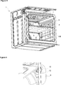
- Figure 3 — is the front perspective view of an oven without the separator therein.
- Figure 4 – is the view of detail A.
- Figure 5 — is the perspective view of an oven wherein the separator is placed.
- Figure 6 — is the view of detail B.
- Figure 7 - is the perspective view of a valve and an opening-closing mechanism.
- Figure 8 - is the top view of the opening-closing mechanism when the resilient member is compressed.
- Figure 9 - is the top view of the opening-closing mechanism when the resilient member is released.
- Figure 10 – is the partial perspective view of a casing and an exterior body.
- Figure 11 – is the partial perspective view of a casing and an exterior body from a different angle.
- the oven (1) comprises an exterior body (2), a casing (3) positioned in the exterior body (2) such that a gap remains therebetween, an oven cavity (4) situated inside the casing (3) wherein the cooking process is performed, a rear wall (5) situated in the oven cavity (4), at least one fan (6) disposed between the exterior body (2) and the casing (3), propelling the air, at least one separator (7) that can be attached to/detached from the oven cavity (4), dividing the oven cavity (4) into more than one volume and at least two compartments (8, 108) inside the oven cavity (4), one situated at the top, the other at the bottom and separated from each other by the separator (7) ( Figure 1).
- the oven (1) furthermore comprises an air line (H) situated between the exterior body (2) and the casing (3) and which enables air to be circulated around the casing (3).
- the air sucked from the outside environment by means of the air line (H), is propelled by the fan (6), circulated around the casing (3) inside the air line (H) and discharged out of the oven (1).
- the outer wall of the exterior body (2) is prevented from overheating and thereby from acting like a heat source.
- the oven (1) of the present invention comprises a discharge line (9), one end opening into the bottom compartment (108), the other end into the volume between the casing (3) and the exterior body (2).
- the inner volume of the oven (1) is divided into two by means of the separator (7) for the aim of cooking different foods at different temperatures.
- the separator (7) is placed into the oven cavity (4) by being pushed towards the rear wall (5) by the user.
- hot and humid air is generated inside the bottom compartment (108).
- the said hot and humid air is delivered to the air line (H) by passing through the discharge line (9) and is discharged from the oven (1).
- the hot and humid air formed inside the bottom compartment (108) is provided to be discharged outside directly. Consequently, condensation in the oven cavity (4) is prevented and cooking effectiveness is increased.
- the oven (1) comprises at least one valve (10) that provides the opening/closing of the front of the discharge line (9) end connected to the oven cavity (4) and at least one opening-closing mechanism (11) that, by moving the valve (10), provides air to be sucked from inside the compartment (108) by opening the front of the discharge line (9) end connected to the oven cavity (4) when the separator (7) is placed into the oven cavity (4) and provides the front of the discharge line (9) end connected to the oven cavity (4) to be closed when the separator (7) is taken out of the oven cavity (4).
- the valve (10) moves away from the front of the discharge line (9) end connected to the oven cavity (4) and opens the front of the discharge line (9) end connected to the oven cavity (4).
- the humid air contained inside the compartment (108) is provided to be discharged outside by passing through the discharge line (9) ( Figure 5, Figure 6).
- the rear wall (5) comprises more than one hole (12) arranged at the front of the discharge line (9) end connected to the oven cavity (4).
- the holes (12) are formed in various numbers and shapes and with different combinations.
- the valve (10) moves by getting away from the front of the holes (12) when the separator (7) approaches the rear wall (5).
- the hot and humid air contained inside the compartment (108) is delivered to the discharge line (9) by passing through the holes (12).
- the discharge line (9) is at least partially shaped as a bend.
- the air in the discharge line (9) is provided to be directed effectively and to be discharged outside by being delivered to the air line (H).
- the discharge line (9) is bent in the flow direction of the air circulating between the exterior body (2) and the casing (3).
- the air leaving the discharge line (9) is directed in the flow direction of the air circulating between the exterior body (2) and the casing (3).
- the humid air contained in the bottom compartment (108) is provided to be discharged from the oven (1) effectively.
- the end of the discharge line (9) remaining in the volume between the exterior body (2) and the casing (3) is in truncated shape.
- almost all of the air passing through the discharge line (9) is provided to leave the discharge line (9) in the same direction and to be delivered to the air line (H).
- the opening-closing mechanism (11) comprises a pusher (13) against which the separator (7) bears when placed in the oven cavity (4) and at least one shaft (14) that moves the valve (10) by rotating around its axis by the movement of the pusher (13).
- the separator (7) bears against the pusher (13) while approaching the rear wall (5).
- the shaft (14) moves as the separator (7) bears against the pusher (13).
- the valve (10) rotates together with the shaft (14) and moves away from the front of the discharge line (9) end opening into the compartment (108).
- the hot and humid air is sucked from inside the compartment (108) by opening the front of the discharge line (9) end connected tothe oven cavity (4) and delivered to the outside environment.
- the opening-closing mechanism (11) comprises at least one gear rack (15) disposed at the rear end of the pusher (13) and at least one pinion (16) that moves on the gear rack (15),moving the shaft (14).
- the separator (7) bears against the pusher (13) while approaching the rear wall (5).
- the gear rack (15) moves as the separator (7) bears against the pusher (13).
- the pinion (16) and the shaft (14) connected to the pinion (16) rotate as well together with the gear rack (15).
- the valve (10) also rotates together with the shaft (14) and moves away from the front of the discharge line (9) end connected to the oven cavity (4).
- the front of the discharge line (9) end connected to the bottom compartment (108) is opened, and the hot and humid air is delivered to the outside environment by being sucked from inside the compartment (108) ( Figure 7, Figure 8, Figure 9).
- the opening-closing mechanism (11) comprises at least one resilient member (17) that provides the pusher (13) to resume its initial position when the separator (7) is taken out of the oven cavity (4).
- the resilient member (17) compressed while the separator (7) is being placed into the oven cavity (4) provides the valve (10) to move and to close the front of the discharge line (9) end connected to the bottom compartment (108) by stretching when the separator (7) is taken out of the oven cavity (4).
- the resilient member (17) is disposed at the rear end of the gear rack (15).
- the separator (7) bears against the pusher (13) while approaching the rear wall (5).
- the gear rack (15) moves as the separator (7) bears against the pusher (13).
- the resilient member (17) is compressed.
- the compression force exerted to the pusher (13) is eliminated with the removal of the separator (7) from the oven cavity (4).
- the force exerted to the gear rack (15) by the pusher (13) is also eliminated.
- the compressed resilient member (17) stretches and provides the valve (10) to be moved.
- the front of the discharge line (9) end connected to the bottom compartment (108) is closed ( Figure 7, Figure 8, Figure 9).
- the resilient member (17) is spring-shaped.
- the shaft (14) extends in the vertical direction.
- the separator (7) bears against the pusher (13) while approaching the rear wall (5).
- the shaft (14) moves as the separator (7) bears against the pusher (13).
- the valve (10) also rotates together with the shaft (14) and moves away from the front of the discharge line (9) end connected to the bottom compartment (108) ( Figure 7).
- an oven (1) is realized wherein the hot and humid air generated inside the bottom compartment (108) is delivered to the outside environment effectively when the separator (7) is placed into the oven cavity (4). Consequently, condensation in the oven cavity (4) is prevented and cooking effectiveness is increased.
Abstract
The present invention relates to an oven (1) comprising an oven cavity (4), a casing (3) that surrounds the oven cavity (4), a rear wall (5) that separates the oven cavity (4) and the space containing the fan (6), at least one blowing hole (12) providing the delivery of the air into the oven cavity (4), at least one separator (7) that can be attached to / detached from the oven cavity (4), dividing the oven cavity (4) into more than one volume, at least two compartments (8, 108) situated in the oven cavity (4), separated from one another by the separator (7) and at least one suction hole (12) situated on the rear wall of the compartment (8, 108) (5), providing air to be sucked from the compartment (8, 108).
Description
The present invention relates to an oven, the ventilating effectiveness of which is increased.
In ovens, the oven cavity is separated into more than one volume by means of aseparator for the aim of cooking different foodstuffs at the same time. Sometimes, one of the separated volumes is heated instead of heating the entire oven cavity for cooking a small amount of food, thus providing energy saving.
The hot and humid air generated during cooking is sucked from inside the oven cavity and discharged from the oven. In an oven divided into two volumes, the hot and humid air generated at the top compartment is discharged outside with the present ventilation means of the oven. The hot and humid air generated at the bottom compartment results in condensation in the top compartment and also in decrease of cooking quality at the bottom compartment since the said air cannot be discharged outside directly.
In the state of the art Japanese Patent Document No. JP58193031, an oven is described, that comprises a separator placed into the cooking chamber and which divides the cooking volume into two. With the separator being placed into the cooking chamber, the front of the intermediate blowing hole, between the main suction hole and the blowing hole, is opened.
The aim of the present invention is the realization of an oven wherein ventilation effectiveness is increased in the separated oven cavity volumes when the separator is placed into the oven cavity.
The oven realized in order to attain the aim of the present invention comprises an exterior body, a casing positioned in the exterior body such that a gap remains therebetween, an oven cavity situated inside the casing and wherein the cooking process is performed, a rear wall situated in the oven cavity, at least one fan disposed between the exterior body and the casing that propels the air, at least one separator that can be attached to/detached from the oven cavity, dividing the oven cavity into more than one volume and at least two compartments inside the oven cavity, one situated at the top, the other at the bottom, and separated from each other by the separator. During operation of the fan, the air sucked from the outside environment is circulated around the casing and delivered to the outside environment. Thus, an air line is formed that circulates between the body and the casing.
The oven of the present invention comprises a discharge line, one end connected inside the bottom compartment, the other end to the volume between the casing and the exterior body. The oven volume is divided into more than one volume by means of the separator in order that the odors do not mix with each other while cooking the foods or that the foods are cooked under different conditions. During the cooking process, the water vapor collected in the bottom compartment passes through the discharge line and is thus directly delivered between the casing and the exterior body. The water vapor passing to between the casing and the exterior body is discharged outside with the air line.
The oven of the present invention comprises at least one valve situated at the front of the discharge line end connected to the oven cavity and at least one opening-closing mechanism that, by moving the valve, provides the front of the discharge line end connected to the oven cavity to be opened when the separator is placed into the oven cavity and provides the front of the discharge line end connected to the oven cavity to be closed when the separator is taken outside the oven cavity. During cooking, the hot and humid air generated inside the bottom compartment passes through the discharge line. The hot and humid air passing to between the casing and the body reaches the air line directed by the fan and is discharged out of the oven. Thus, formation of condensation inside the oven cavity is prevented.
In an embodiment of the present invention, the rear wall comprises more than one hole arranged at the front of the discharge line end opening into the oven cavity. The valve moves by getting away from the front of the holes when the separator approaches the rear wall. Thus, air is provided to pass from the holes to the discharge line. The hot and humid air contained inside the compartment is delivered to the discharge line by passing through the holes. The air sucking direction can be changed by means of the holes and the valve.
In an embodiment of the present invention, the discharge line is almost shaped as a bend. By means of the said shape, the air contained in the discharge line is provided to be directed effectively.
In an embodiment of the present invention, the discharge line has a shape that enables the humid air leaving therefrom to merge with the air circulating between the exterior body and the casing. Thus, the water vapor generated inside the bottom compartment during cooking is directly discharged outside with the air line by passing through the discharge line.
In an embodiment of the present invention, the end of the discharge line remaining between the exterior body and the casing is in truncated shape. Thus, almost all of the air passing through the discharge line is provided to leave the discharge line in the same direction and to be directed towards the air line.
In an embodiment of the present invention, the opening-closing mechanism comprises a pusher against which the separator bears when placed into the oven cavity and at least one shaft that moves the valve by rotating around its axis when actuated by the pusher. The separator actuates the pusher and moves the pusher while being placed into the oven cavity. The shaft, connected to the pusher, rotates as well, and provides the valve to be moved by rotating. Thus, the front of the end of the discharge line connected to the oven cavity is opened.
In an embodiment of the present invention, the opening-closing mechanism comprises at least one gear rack against which the pusher bears and at least one pinion that bear against the gear rack and moves the shaft. The separator actuates the pusher and moves the pusher while being placed into the oven cavity. The gear rack moves as well, being connected to the pusher. The pinion rotates with the motion of the gear rack as well and the shaft being connected to the pinion also rotates. Thus, the valve moves away from the front of the discharge line end opening into the bottom compartment. The front of the discharge line end opening into the bottom compartment is opened and thus air from the bottom compartment is provided to pass into the discharge line.
In an embodiment of the present invention, the opening-closing mechanism comprises a resilient member that provides the pusher to resume its initial position when the separator is taken out of the oven cavity. The resilient member is compressed while the separator is being placed into the oven cavity. The compressed resilient member stretches while the separator is removed from the oven cavity and provides the valve to be moved.
In an embodiment of the present invention, the opening-closing mechanism comprises at least one resilient member against which the gear rack bears. As the gear rack moves, the resilient member is compressed between the gear rack and the body wall. As the separator is removed from the oven cavity, the gear rack and the pusher are released and thus the compression force exerted on the resilient member is removed. The resilient member stretches and provides the valve to be moved.
In an embodiment of the present invention, the resilient member is spring-shaped.
In an embodiment of the present invention, the shaft extends in the vertical plane. The shaft is situated on the diameter of the valve in the vertical axis. As the shaft moves, the valve also moves by rotating.
By means of the present invention, an oven is realized wherein the formation of condensation in one compartment due to increase of temperature in the other compartment is prevented and the ventilation effectiveness is increased while performing cooking in different compartments.
An oven realized in order to attain the aim of the present invention is illustrated in the attached figures, where:
Figure 1 – is the front perspective view of an oven.
Figure 2 – is the sideways perspective view of an oven.
Figure 3 – is the front perspective view of an oven without the separator therein.
Figure 4 – is the view of detail A.
Figure 5 – is the perspective view of an oven wherein the separator is placed.
Figure 6 – is the view of detail B.
Figure 7 - is the perspective view of a valve and an opening-closing mechanism.
Figure 8 - is the top view of the opening-closing mechanism when the resilient member is compressed.
Figure 9 - is the top view of the opening-closing mechanism when the resilient member is released.
Figure 10 – is the partial perspective view of a casing and an exterior body.
Figure 11 – is the partial perspective view of a casing and an exterior body from a different angle.
The elements illustrated in the figures are numbered as follows:
- Oven
- Exterior body
- Casing
- Oven cavity
- Rear wall
- Fan
- Separator
- 108. Compartment
- Discharge line
- Valve
- Opening-closing mechanism
- Hole
- Pusher
- Shaft
- Gear rack
- Pinion
- Resilient member
The oven (1) comprises an exterior body (2), a casing (3) positioned in the exterior body (2) such that a gap remains therebetween, an oven cavity (4) situated inside the casing (3) wherein the cooking process is performed, a rear wall (5) situated in the oven cavity (4), at least one fan (6) disposed between the exterior body (2) and the casing (3), propelling the air, at least one separator (7) that can be attached to/detached from the oven cavity (4), dividing the oven cavity (4) into more than one volume and at least two compartments (8, 108) inside the oven cavity (4), one situated at the top, the other at the bottom and separated from each other by the separator (7) (Figure 1).
The oven (1) furthermore comprises an air line (H) situated between the exterior body (2) and the casing (3) and which enables air to be circulated around the casing (3). The air sucked from the outside environment by means of the air line (H), is propelled by the fan (6), circulated around the casing (3) inside the air line (H) and discharged out of the oven (1). Thus, the outer wall of the exterior body (2) is prevented from overheating and thereby from acting like a heat source.
The oven (1) of the present invention comprises a discharge line (9), one end opening into the bottom compartment (108), the other end into the volume between the casing (3) and the exterior body (2). The inner volume of the oven (1) is divided into two by means of the separator (7) for the aim of cooking different foods at different temperatures. The separator (7) is placed into the oven cavity (4) by being pushed towards the rear wall (5) by the user. During the cooking process, hot and humid air is generated inside the bottom compartment (108). The said hot and humid air is delivered to the air line (H) by passing through the discharge line (9) and is discharged from the oven (1). Thus, the hot and humid air formed inside the bottom compartment (108) is provided to be discharged outside directly. Consequently, condensation in the oven cavity (4) is prevented and cooking effectiveness is increased.
In an embodiment of the present invention, the oven (1) comprises at least one valve (10) that provides the opening/closing of the front of the discharge line (9) end connected to the oven cavity (4) and at least one opening-closing mechanism (11) that, by moving the valve (10), provides air to be sucked from inside the compartment (108) by opening the front of the discharge line (9) end connected to the oven cavity (4) when the separator (7) is placed into the oven cavity (4) and provides the front of the discharge line (9) end connected to the oven cavity (4) to be closed when the separator (7) is taken out of the oven cavity (4). When the separator (7) is placed into the oven cavity (4), the valve (10) moves away from the front of the discharge line (9) end connected to the oven cavity (4) and opens the front of the discharge line (9) end connected to the oven cavity (4). Thus, the humid air contained inside the compartment (108) is provided to be discharged outside by passing through the discharge line (9) (Figure 5, Figure 6).
When the separator (7) is taken out of the oven cavity (4), the front of the discharge line (9) end connected to the oven cavity (4) is closed by means of the valve (10) and air suction from the bottom compartment (108) is not realized. Consequently, air is provided to circulate homogeneously inside the oven cavity (4) when the separator (7) is not placed into the oven cavity (4) (Figure 3, Figure 4).
In an embodiment of the present invention, the rear wall (5) comprises more than one hole (12) arranged at the front of the discharge line (9) end connected to the oven cavity (4). The holes (12) are formed in various numbers and shapes and with different combinations. The valve (10) moves by getting away from the front of the holes (12) when the separator (7) approaches the rear wall (5). Thus, the hot and humid air contained inside the compartment (108) is delivered to the discharge line (9) by passing through the holes (12).
In an embodiment of the present invention, the discharge line (9) is at least partially shaped as a bend. By means of the bend shape, the air in the discharge line (9) is provided to be directed effectively and to be discharged outside by being delivered to the air line (H).
In an embodiment of the present invention, the discharge line (9) is bent in the flow direction of the air circulating between the exterior body (2) and the casing (3). Thus, the air leaving the discharge line (9) is directed in the flow direction of the air circulating between the exterior body (2) and the casing (3). The humid air contained in the bottom compartment (108) is provided to be discharged from the oven (1) effectively.
In an embodiment of the present invention, the end of the discharge line (9) remaining in the volume between the exterior body (2) and the casing (3) is in truncated shape. Thus, almost all of the air passing through the discharge line (9) is provided to leave the discharge line (9) in the same direction and to be delivered to the air line (H).
In an embodiment of the present invention, the opening-closing mechanism (11) comprises a pusher (13) against which the separator (7) bears when placed in the oven cavity (4) and at least one shaft (14) that moves the valve (10) by rotating around its axis by the movement of the pusher (13). The separator (7) bears against the pusher (13) while approaching the rear wall (5). The shaft (14) moves as the separator (7) bears against the pusher (13). The valve (10) rotates together with the shaft (14) and moves away from the front of the discharge line (9) end opening into the compartment (108). Thus, the hot and humid air is sucked from inside the compartment (108) by opening the front of the discharge line (9) end connected tothe oven cavity (4) and delivered to the outside environment.
In an embodiment of the present invention, the opening-closing mechanism (11) comprises at least one gear rack (15) disposed at the rear end of the pusher (13) and at least one pinion (16) that moves on the gear rack (15),moving the shaft (14). The separator (7) bears against the pusher (13) while approaching the rear wall (5). The gear rack (15) moves as the separator (7) bears against the pusher (13). The pinion (16) and the shaft (14) connected to the pinion (16) rotate as well together with the gear rack (15). The valve (10) also rotates together with the shaft (14) and moves away from the front of the discharge line (9) end connected to the oven cavity (4). Thus, the front of the discharge line (9) end connected to the bottom compartment (108) is opened, and the hot and humid air is delivered to the outside environment by being sucked from inside the compartment (108) (Figure 7, Figure 8, Figure 9).
In an embodiment of the present invention, the opening-closing mechanism (11) comprises at least one resilient member (17) that provides the pusher (13) to resume its initial position when the separator (7) is taken out of the oven cavity (4). The resilient member (17) compressed while the separator (7) is being placed into the oven cavity (4) provides the valve (10) to move and to close the front of the discharge line (9) end connected to the bottom compartment (108) by stretching when the separator (7) is taken out of the oven cavity (4).
In an embodiment of the present invention, the resilient member (17) is disposed at the rear end of the gear rack (15). The separator (7) bears against the pusher (13) while approaching the rear wall (5). The gear rack (15) moves as the separator (7) bears against the pusher (13). In the meantime, the resilient member (17) is compressed. The compression force exerted to the pusher (13) is eliminated with the removal of the separator (7) from the oven cavity (4). Thus, the force exerted to the gear rack (15) by the pusher (13) is also eliminated. As the gear rack (15) is released, the compressed resilient member (17) stretches and provides the valve (10) to be moved. Thus, the front of the discharge line (9) end connected to the bottom compartment (108) is closed (Figure 7, Figure 8, Figure 9).
In an embodiment of the present invention, the resilient member (17) is spring-shaped.
In an embodiment of the present invention, the shaft (14) extends in the vertical direction. The separator (7) bears against the pusher (13) while approaching the rear wall (5). The shaft (14) moves as the separator (7) bears against the pusher (13). The valve (10) also rotates together with the shaft (14) and moves away from the front of the discharge line (9) end connected to the bottom compartment (108) (Figure 7).
By means of the present invention, an oven (1) is realized wherein the hot and humid air generated inside the bottom compartment (108) is delivered to the outside environment effectively when the separator (7) is placed into the oven cavity (4). Consequently, condensation in the oven cavity (4) is prevented and cooking effectiveness is increased.
It is to be understood that the present invention is not limited by the embodiments disclosed above and a person skilled in the art can easily introduce different embodiments. These should be considered within the scope of the protection postulated by the claims of the present invention.
Claims (12)
- An oven (1) comprising- an exterior body (2),- a casing (3) positioned in the exterior body (2) such that a gap remains therebetween,- an oven cavity (4) disposed inside the casing (3), wherein the cooking process is performed,- a rear wall (5) situated in the oven cavity (4),- at least one fan (6) disposed between the exterior body (2) and the casing (3), moving the air,- at least one separator (7) that can be attached to/detached from the oven cavity (4), dividing the oven cavity (4) into more than one volume,- at least two compartments (8, 108) inside the oven cavity (4), one situated at the top, the other at the bottom, separated from each other by the separator (7),characterized in that- a discharge line (9), one end opening into the bottom compartment (108), the other end into the volume between the casing (3) and the exterior body (2).
- An oven (1) as in Claim 1, characterized in that at least one valve (10) that provides the opening/closing of the front of the discharge line (9) end connected to the oven cavity (4) and at least one opening-closing mechanism (11) that, by moving the valve (10), provides air to be sucked from inside the compartment (108) by opening the front of the discharge line (9) end connected to the oven cavity (4) when the separator (7) is placed into the oven cavity (4), and provides the front of the discharge line (9) end connected to the oven cavity (4) to be closed when the separator (7) is taken out of the oven cavity (4).
- An oven (1) as in Claim 1 or 2, characterized in that the rear wall (5) having more than one hole (12) arranged at the front of the discharge line (9) end connected to the oven cavity (4).
- An oven (1) as in any one of Claims 1 to 3, characterized in that the discharge line (9) that is at least partially shaped as a bend.
- An oven (1) as in any one of Claims 1 to 4, characterized in that the discharge line (9) that is bent in the direction of the air flow circulating between the exterior body (2) and the casing (3).
- An oven (1) as in any one of the above Claims, characterized in that the discharge line (9), the end of which remaining between the exterior body (2) and the casing (3) is in truncated shape.
- An oven (1) as in any one of the above Claims, characterized in that the opening-closing mechanism (11) comprising a pusher (13) against which the separator (7) bears when placed in the oven cavity (4) and at least one shaft (14) that moves the valve (10) by rotating around its axis by the movement of the pusher (13).
- An oven (1) as in Claim 7, characterized in that the opening-closing mechanism (11) having at least one gear rack (15) disposed behind the pusher (13) and at least one pinion (16) that moves on the gear rack (15), moving the shaft (14).
- An oven (1) as in Claim 7 or 8, characterized in that the opening-closing mechanism (11) having a resilient member (17) that provides the pusher (13) to resume its initial position when the separator (7) is taken out of the oven cavity (4).
- An oven (1) as in Claim 9, characterized in that the resilient member (17) that is disposed at the rear end of the gear rack (15).
- An oven (1) as in Claim 9 or 10, characterized in that the spring-shaped resilient member (17).
- An oven (7) as in any one of Claims 7 to 11, characterized in that the shaft (14) that extends in the vertical direction.
Priority Applications (1)
| Application Number | Priority Date | Filing Date | Title |
|---|---|---|---|
| EP13723174.2A EP2859275A1 (en) | 2012-06-06 | 2013-05-18 | An oven with increased ventilating effectiveness |
Applications Claiming Priority (2)
| Application Number | Priority Date | Filing Date | Title |
|---|---|---|---|
| TRA2012/06622 | 2012-06-06 | ||
| TR201206622 | 2012-06-06 |
Publications (1)
| Publication Number | Publication Date |
|---|---|
| WO2013182410A1 true WO2013182410A1 (en) | 2013-12-12 |
Family
ID=48446389
Family Applications (1)
| Application Number | Title | Priority Date | Filing Date |
|---|---|---|---|
| PCT/EP2013/060321 WO2013182410A1 (en) | 2012-06-06 | 2013-05-18 | An oven with increased ventilating effectiveness |
Country Status (2)
| Country | Link |
|---|---|
| EP (1) | EP2859275A1 (en) |
| WO (1) | WO2013182410A1 (en) |
Cited By (10)
| Publication number | Priority date | Publication date | Assignee | Title |
|---|---|---|---|---|
| US10145568B2 (en) | 2016-06-27 | 2018-12-04 | Whirlpool Corporation | High efficiency high power inner flame burner |
| USD835775S1 (en) | 2015-09-17 | 2018-12-11 | Whirlpool Corporation | Gas burner |
| US10451290B2 (en) | 2017-03-07 | 2019-10-22 | Whirlpool Corporation | Forced convection steam assembly |
| US10551056B2 (en) | 2017-02-23 | 2020-02-04 | Whirlpool Corporation | Burner base |
| US10619862B2 (en) | 2018-06-28 | 2020-04-14 | Whirlpool Corporation | Frontal cooling towers for a ventilation system of a cooking appliance |
| US10627116B2 (en) | 2018-06-26 | 2020-04-21 | Whirlpool Corporation | Ventilation system for cooking appliance |
| US10660162B2 (en) | 2017-03-16 | 2020-05-19 | Whirlpool Corporation | Power delivery system for an induction cooktop with multi-output inverters |
| US10837652B2 (en) | 2018-07-18 | 2020-11-17 | Whirlpool Corporation | Appliance secondary door |
| US10837651B2 (en) | 2015-09-24 | 2020-11-17 | Whirlpool Corporation | Oven cavity connector for operating power accessory trays for cooking appliance |
| US11777190B2 (en) | 2015-12-29 | 2023-10-03 | Whirlpool Corporation | Appliance including an antenna using a portion of appliance as a ground plane |
Citations (6)
| Publication number | Priority date | Publication date | Assignee | Title |
|---|---|---|---|---|
| JPS58193031A (en) | 1982-05-07 | 1983-11-10 | Matsushita Electric Ind Co Ltd | Oven |
| EP0641976A1 (en) * | 1993-09-04 | 1995-03-08 | AEG Hausgeräte GmbH | Electrical baking and roasting stove |
| EP1698832A2 (en) * | 2005-03-02 | 2006-09-06 | Samsung Electronics Co., Ltd. | Oven |
| EP2003400A2 (en) * | 2007-06-13 | 2008-12-17 | Samsung Electronics Co., Ltd. | Cooking apparatus with divider |
| EP2083223A1 (en) * | 2006-11-02 | 2009-07-29 | Sharp Kabushiki Kaisha | Device for diluting discharged vapor and cooker with the same |
| EP2322859A1 (en) * | 2008-08-29 | 2011-05-18 | Sharp Kabushiki Kaisha | Cooking device |
-
2013
- 2013-05-18 WO PCT/EP2013/060321 patent/WO2013182410A1/en active Application Filing
- 2013-05-18 EP EP13723174.2A patent/EP2859275A1/en not_active Withdrawn
Patent Citations (6)
| Publication number | Priority date | Publication date | Assignee | Title |
|---|---|---|---|---|
| JPS58193031A (en) | 1982-05-07 | 1983-11-10 | Matsushita Electric Ind Co Ltd | Oven |
| EP0641976A1 (en) * | 1993-09-04 | 1995-03-08 | AEG Hausgeräte GmbH | Electrical baking and roasting stove |
| EP1698832A2 (en) * | 2005-03-02 | 2006-09-06 | Samsung Electronics Co., Ltd. | Oven |
| EP2083223A1 (en) * | 2006-11-02 | 2009-07-29 | Sharp Kabushiki Kaisha | Device for diluting discharged vapor and cooker with the same |
| EP2003400A2 (en) * | 2007-06-13 | 2008-12-17 | Samsung Electronics Co., Ltd. | Cooking apparatus with divider |
| EP2322859A1 (en) * | 2008-08-29 | 2011-05-18 | Sharp Kabushiki Kaisha | Cooking device |
Cited By (12)
| Publication number | Priority date | Publication date | Assignee | Title |
|---|---|---|---|---|
| USD835775S1 (en) | 2015-09-17 | 2018-12-11 | Whirlpool Corporation | Gas burner |
| US10837651B2 (en) | 2015-09-24 | 2020-11-17 | Whirlpool Corporation | Oven cavity connector for operating power accessory trays for cooking appliance |
| US11460195B2 (en) | 2015-09-24 | 2022-10-04 | Whirlpool Corporation | Oven cavity connector for operating power accessory trays for cooking appliance |
| US11777190B2 (en) | 2015-12-29 | 2023-10-03 | Whirlpool Corporation | Appliance including an antenna using a portion of appliance as a ground plane |
| US10145568B2 (en) | 2016-06-27 | 2018-12-04 | Whirlpool Corporation | High efficiency high power inner flame burner |
| US10551056B2 (en) | 2017-02-23 | 2020-02-04 | Whirlpool Corporation | Burner base |
| US10451290B2 (en) | 2017-03-07 | 2019-10-22 | Whirlpool Corporation | Forced convection steam assembly |
| US10660162B2 (en) | 2017-03-16 | 2020-05-19 | Whirlpool Corporation | Power delivery system for an induction cooktop with multi-output inverters |
| US10627116B2 (en) | 2018-06-26 | 2020-04-21 | Whirlpool Corporation | Ventilation system for cooking appliance |
| US11226106B2 (en) | 2018-06-26 | 2022-01-18 | Whirlpool Corporation | Ventilation system for cooking appliance |
| US10619862B2 (en) | 2018-06-28 | 2020-04-14 | Whirlpool Corporation | Frontal cooling towers for a ventilation system of a cooking appliance |
| US10837652B2 (en) | 2018-07-18 | 2020-11-17 | Whirlpool Corporation | Appliance secondary door |
Also Published As
| Publication number | Publication date |
|---|---|
| EP2859275A1 (en) | 2015-04-15 |
Similar Documents
| Publication | Publication Date | Title |
|---|---|---|
| WO2013182410A1 (en) | An oven with increased ventilating effectiveness | |
| EP2764295B1 (en) | An oven with increased cooking efficiency | |
| KR101934903B1 (en) | Apparatus for preparing food | |
| KR100767850B1 (en) | Electric oven | |
| EP2857756A1 (en) | Oven | |
| JP4528849B2 (en) | Drawer type cooking device | |
| CN208582202U (en) | A kind of steam box oven all-in-one machine | |
| WO2017215926A1 (en) | An air-based cooker | |
| EP3029382B1 (en) | Kitchen appliance comprising a humidity flushing system | |
| BR112013005507B1 (en) | FOOD PREPARATION APPARATUS | |
| KR20100091683A (en) | Microwave oven having hood | |
| JP6790247B2 (en) | Ventilation device with air intake | |
| CN109965676A (en) | A kind of steam box oven all-in-one machine | |
| WO2007125123A1 (en) | An oven | |
| WO2008148846A1 (en) | An oven | |
| EP3059504A1 (en) | Kitchen oven | |
| ES2210875T3 (en) | KITCHEN OVEN WITH SUCTION BOX. | |
| CN107894014B (en) | Heating cooker | |
| EP2013543B1 (en) | Oven | |
| CN209877015U (en) | Integrated stove with cooking device | |
| CN115120088B (en) | Cooking device and integrated stove with same | |
| EP2519776B1 (en) | Oven with a ventilating duct | |
| CN208463633U (en) | Cooking apparatus | |
| WO2011026819A3 (en) | An oven whereof heat losses are decreased | |
| JP5405186B2 (en) | Cooker |
Legal Events
| Date | Code | Title | Description |
|---|---|---|---|
| 121 | Ep: the epo has been informed by wipo that ep was designated in this application |
Ref document number: 13723174 Country of ref document: EP Kind code of ref document: A1 |
|
| WWE | Wipo information: entry into national phase |
Ref document number: 2013723174 Country of ref document: EP |
|
| NENP | Non-entry into the national phase |
Ref country code: DE |