WO2013176265A1 - Pupil detection method, corneal reflex detection method, facial posture detection method, and pupil tracking method - Google Patents
Pupil detection method, corneal reflex detection method, facial posture detection method, and pupil tracking method Download PDFInfo
- Publication number
- WO2013176265A1 WO2013176265A1 PCT/JP2013/064511 JP2013064511W WO2013176265A1 WO 2013176265 A1 WO2013176265 A1 WO 2013176265A1 JP 2013064511 W JP2013064511 W JP 2013064511W WO 2013176265 A1 WO2013176265 A1 WO 2013176265A1
- Authority
- WO
- WIPO (PCT)
- Prior art keywords
- pupil
- camera
- image
- pair
- subject
- Prior art date
Links
- 0 CCC1(C(C2)C(C(C3)CC3*3CC3)C2*1)C(*)(*C)C1C=CC1C(C1)CC1*(C)* Chemical compound CCC1(C(C2)C(C(C3)CC3*3CC3)C2*1)C(*)(*C)C1C=CC1C(C1)CC1*(C)* 0.000 description 3
Images


Classifications
-
- A—HUMAN NECESSITIES
- A61—MEDICAL OR VETERINARY SCIENCE; HYGIENE
- A61B—DIAGNOSIS; SURGERY; IDENTIFICATION
- A61B3/00—Apparatus for testing the eyes; Instruments for examining the eyes
- A61B3/10—Objective types, i.e. instruments for examining the eyes independent of the patients' perceptions or reactions
- A61B3/11—Objective types, i.e. instruments for examining the eyes independent of the patients' perceptions or reactions for measuring interpupillary distance or diameter of pupils
- A61B3/111—Objective types, i.e. instruments for examining the eyes independent of the patients' perceptions or reactions for measuring interpupillary distance or diameter of pupils for measuring interpupillary distance
-
- G—PHYSICS
- G06—COMPUTING; CALCULATING OR COUNTING
- G06V—IMAGE OR VIDEO RECOGNITION OR UNDERSTANDING
- G06V40/00—Recognition of biometric, human-related or animal-related patterns in image or video data
- G06V40/10—Human or animal bodies, e.g. vehicle occupants or pedestrians; Body parts, e.g. hands
- G06V40/18—Eye characteristics, e.g. of the iris
- G06V40/197—Matching; Classification
-
- A—HUMAN NECESSITIES
- A61—MEDICAL OR VETERINARY SCIENCE; HYGIENE
- A61B—DIAGNOSIS; SURGERY; IDENTIFICATION
- A61B3/00—Apparatus for testing the eyes; Instruments for examining the eyes
- A61B3/10—Objective types, i.e. instruments for examining the eyes independent of the patients' perceptions or reactions
- A61B3/113—Objective types, i.e. instruments for examining the eyes independent of the patients' perceptions or reactions for determining or recording eye movement
-
- G—PHYSICS
- G06—COMPUTING; CALCULATING OR COUNTING
- G06F—ELECTRIC DIGITAL DATA PROCESSING
- G06F3/00—Input arrangements for transferring data to be processed into a form capable of being handled by the computer; Output arrangements for transferring data from processing unit to output unit, e.g. interface arrangements
- G06F3/01—Input arrangements or combined input and output arrangements for interaction between user and computer
- G06F3/011—Arrangements for interaction with the human body, e.g. for user immersion in virtual reality
- G06F3/013—Eye tracking input arrangements
-
- G—PHYSICS
- G06—COMPUTING; CALCULATING OR COUNTING
- G06F—ELECTRIC DIGITAL DATA PROCESSING
- G06F3/00—Input arrangements for transferring data to be processed into a form capable of being handled by the computer; Output arrangements for transferring data from processing unit to output unit, e.g. interface arrangements
- G06F3/01—Input arrangements or combined input and output arrangements for interaction between user and computer
- G06F3/03—Arrangements for converting the position or the displacement of a member into a coded form
- G06F3/033—Pointing devices displaced or positioned by the user, e.g. mice, trackballs, pens or joysticks; Accessories therefor
- G06F3/0346—Pointing devices displaced or positioned by the user, e.g. mice, trackballs, pens or joysticks; Accessories therefor with detection of the device orientation or free movement in a 3D space, e.g. 3D mice, 6-DOF [six degrees of freedom] pointers using gyroscopes, accelerometers or tilt-sensors
-
- G—PHYSICS
- G06—COMPUTING; CALCULATING OR COUNTING
- G06T—IMAGE DATA PROCESSING OR GENERATION, IN GENERAL
- G06T7/00—Image analysis
- G06T7/50—Depth or shape recovery
- G06T7/55—Depth or shape recovery from multiple images
- G06T7/593—Depth or shape recovery from multiple images from stereo images
-
- G—PHYSICS
- G06—COMPUTING; CALCULATING OR COUNTING
- G06T—IMAGE DATA PROCESSING OR GENERATION, IN GENERAL
- G06T7/00—Image analysis
- G06T7/70—Determining position or orientation of objects or cameras
- G06T7/73—Determining position or orientation of objects or cameras using feature-based methods
-
- G—PHYSICS
- G06—COMPUTING; CALCULATING OR COUNTING
- G06V—IMAGE OR VIDEO RECOGNITION OR UNDERSTANDING
- G06V40/00—Recognition of biometric, human-related or animal-related patterns in image or video data
- G06V40/10—Human or animal bodies, e.g. vehicle occupants or pedestrians; Body parts, e.g. hands
- G06V40/16—Human faces, e.g. facial parts, sketches or expressions
- G06V40/168—Feature extraction; Face representation
- G06V40/171—Local features and components; Facial parts ; Occluding parts, e.g. glasses; Geometrical relationships
-
- G—PHYSICS
- G06—COMPUTING; CALCULATING OR COUNTING
- G06V—IMAGE OR VIDEO RECOGNITION OR UNDERSTANDING
- G06V40/00—Recognition of biometric, human-related or animal-related patterns in image or video data
- G06V40/10—Human or animal bodies, e.g. vehicle occupants or pedestrians; Body parts, e.g. hands
- G06V40/18—Eye characteristics, e.g. of the iris
- G06V40/19—Sensors therefor
-
- A—HUMAN NECESSITIES
- A61—MEDICAL OR VETERINARY SCIENCE; HYGIENE
- A61B—DIAGNOSIS; SURGERY; IDENTIFICATION
- A61B3/00—Apparatus for testing the eyes; Instruments for examining the eyes
- A61B3/10—Objective types, i.e. instruments for examining the eyes independent of the patients' perceptions or reactions
- A61B3/14—Arrangements specially adapted for eye photography
- A61B3/15—Arrangements specially adapted for eye photography with means for aligning, spacing or blocking spurious reflection ; with means for relaxing
- A61B3/156—Arrangements specially adapted for eye photography with means for aligning, spacing or blocking spurious reflection ; with means for relaxing for blocking
- A61B3/158—Arrangements specially adapted for eye photography with means for aligning, spacing or blocking spurious reflection ; with means for relaxing for blocking of corneal reflection
-
- G—PHYSICS
- G06—COMPUTING; CALCULATING OR COUNTING
- G06T—IMAGE DATA PROCESSING OR GENERATION, IN GENERAL
- G06T2207/00—Indexing scheme for image analysis or image enhancement
- G06T2207/10—Image acquisition modality
- G06T2207/10004—Still image; Photographic image
- G06T2207/10012—Stereo images
-
- G—PHYSICS
- G06—COMPUTING; CALCULATING OR COUNTING
- G06T—IMAGE DATA PROCESSING OR GENERATION, IN GENERAL
- G06T2207/00—Indexing scheme for image analysis or image enhancement
- G06T2207/30—Subject of image; Context of image processing
- G06T2207/30004—Biomedical image processing
- G06T2207/30041—Eye; Retina; Ophthalmic
-
- G—PHYSICS
- G06—COMPUTING; CALCULATING OR COUNTING
- G06T—IMAGE DATA PROCESSING OR GENERATION, IN GENERAL
- G06T2207/00—Indexing scheme for image analysis or image enhancement
- G06T2207/30—Subject of image; Context of image processing
- G06T2207/30196—Human being; Person
- G06T2207/30201—Face
Definitions
- the present invention relates to a pupil detection method, a corneal reflection detection method, a face posture detection method, and a pupil tracking method for tracking a subject's pupil based on a captured image. It is about.
- Techniques for detecting the subject's pupil include, for example, gaze detection for medical examination and man-machine interface (see Patent Literature 1 below), sleepiness detection of a subject driving a vehicle (see Patent Literature 2 below) and face It can be used for a direction detection (see Patent Documents 3 and 4 below), a pupil mouse (see Patent Document 5 below) that performs input to a computer or game device without using a finger by the movement of the subject's pupil.
- the inventor has developed a technique for detecting a pupil from an image photographed by a camera.
- the detection of the pupil uses a method of distinguishing the pupil portion from the surrounding image by subtracting the bright pupil image and the dark pupil image captured by the camera.
- a light source such as near-infrared light
- the subject's face is irradiated with light along the optical axis of the camera
- the light reaches the retina from the pupil and is reflected, and the lens and cornea are reflected. Go back to the camera opening.
- the pupil is photographed brightly, and this image is referred to as a bright pupil image.
- the subject's face is illuminated with light from a light source away from the camera opening, the light reflected from the retina hardly enters the camera opening, so the pupil is photographed darkly.
- This is called a pupil image.
- the size of the pupil changes depending on the brightness of the surroundings, and becomes small and difficult to detect particularly in bright places.
- the subject is a spectacle wearer, a part of the spectacles in the vicinity of the pupil causes reflection, and the spectacle reflection is reflected, so that the detection of the pupil from a single image is a bright pupil image or Any of the dark pupil images is difficult.
- the surrounding portions other than the pupil portion have almost the same brightness in both images. Only the relief will be. Thereby, the pupil can be easily detected.
- the present inventor has proposed a differential position correction method using a face posture (see, for example, Patent Document 9).
- the detection range of the line of sight or the gazing point is limited to a range of about 0 to 30 degrees around the camera. Therefore, when it is desired to detect a gazing point or the like in a wide range in front of the subject, the position of the camera cannot be extremely lowered with respect to the subject's face. For this reason, when gaze detection or gazing point detection is performed, it is difficult to detect the nostril due to the fact that the position of the camera cannot be lowered, and at the same time, eyeglass reflection tends to appear.
- a situation in which the nostril cannot be detected or a situation in which the spectacle lens reflection overlaps the pupil is likely to occur depending on the orientation of the user's head.
- the spectacle reflection image may be erroneously detected as the pupil. Once erroneous detection is performed, the erroneously detected spectacle reflection image is tracked and the pupil cannot be detected correctly.
- the present invention has been made to solve these problems, and a pupil detection method and tracking method capable of improving robustness and accuracy without restricting the rotation state of the user's head and the camera position.
- the purpose is to provide.
- a pupil detection method includes a first step of capturing a first image by capturing a face of a target person using a first camera and a target person using a second camera.
- a sixth step of extracting two or more candidate points in the space by using the points in the three-dimensional space corresponding to the set points as candidate points in the space, and in the two spaces from the extracted candidate points in the space A seventh step of selecting a candidate point pair and calculating a distance between the selected two candidate point pairs in space for a plurality of candidate point pairs in space; An eighth step of excluding spatial candidate point pairs whose distances between candidate point pairs are not within a predetermined range; and one or more spatial candidate point pairs out of the spatial candidate point pairs not excluded
- the first image and the second image are respectively acquired by the first camera and the second camera, the first image candidate point is extracted from the first image, and the second Candidate points in the second image are extracted from the image. Then, for the combination of the candidate point in the first image and the candidate point in the second image, it is determined whether or not the combination corresponds to the same point in the three-dimensional space, and the first determined to correspond to the same point Regarding a combination of the candidate point in the image and the candidate point in the second image, a point in the three dictionary space corresponding to the combination is set as a candidate point in the space.
- a pair of candidate points in space is selected from the extracted candidate points in space, and a calculation is performed to calculate the distance between the selected pairs, and the calculated distance is not within a predetermined range.
- the pair is excluded, and one or more pairs of candidate points in the space are selected from the pairs that are not excluded. Therefore, if the pupil is reflected in the images acquired by the two cameras, the pupil can be detected, and thus robustness and accuracy can be improved without restricting the rotation state of the user's head and the camera position. Can be improved.
- a corneal reflection detection method includes a nineteenth step of detecting the subject's pupil by the pupil detection method described above, and one or more candidate corneal reflection candidates from the first image.
- a twentieth step of extracting corneal reflection candidate points in the first image a twenty-first step of extracting one or more second corneal reflection candidate points that are candidates for corneal reflection of the subject from the second image, and extraction
- Corresponding to the combination of the selected first corneal reflection candidate point in the second image and the second corneal reflection candidate point in the second image based on the coordinates and the in-image coordinates of the selected second corneal reflection candidate point in the second image.
- Calculate 3D coordinates If the position of the calculated three-dimensional coordinates and the detected three-dimensional coordinates of the pupil are within a predetermined range, the calculated three-dimensional coordinates
- the face posture detection method detects the face posture of the subject based on the three-dimensional coordinates of the pair of pupils of the subject detected by the above-described pupil detection method.
- the pupil tracking method is the 25th step of detecting a pair of pupils of the subject by the pupil detection method described above, and the face of the subject by each of the first camera and the second camera.
- a pair of subjects at a first time after the 26th step of capturing an image and acquiring an image, a step of detecting a pair of pupil pairs, and a second time after the first time A twenty-seventh step of detecting a pupil pair, a twenty-eighth step of calculating absolute and relative positions of the pair of pupil pairs detected at the first time and the second time, and the calculated first time and first 29th step of estimating the absolute position and relative position of the pair of pupil pairs at the third time after the second time based on the absolute position and relative position of the pair of pupil pairs at the time of 2 is estimated.
- the third time A 30th step of estimating in-image coordinates of each pupil of the pair of pupil pairs at a third time based on the absolute position and relative position of the pair of pupil pairs at In each of the images taken by the two cameras, a 31st step of setting a small area around the estimated intra-coordinate coordinates of the pupil, and the images taken by the first camera and the second camera at the third time In each of the steps, a thirty-second step is provided in which the position of the pupil is determined by predetermined image processing in the set small region, and the intra-image coordinates of the pupil at the third time are calculated.
- the present invention it is possible to provide a pupil detection method and a tracking method that can improve robustness and accuracy without restricting the rotation state of the user's head and the camera position.
- This pupil detection device is used as a pointing device that moves a cursor on a monitor screen of a personal computer by detecting pupil movement, a drowsiness detection system that detects movement of the pupil and detects driver drowsiness, etc. .
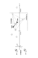
- FIG. 1 is a plan view showing a pupil detection device 10 which is a preferred embodiment of the present invention.
- the pupil detection device 10 is located in the vicinity of the left camera 2A and the right camera 2B, which are two cameras that capture the head image of the subject A, and the imaging lens on the front surface 2a of the left camera 2A.
- a light source 3a provided, a light source 3b provided at a position away from the front surface 2a of the left camera 2A, a light source 3c provided in the vicinity of the imaging lens of the front surface 2b of the right camera 2B, and a front surface 2b of the right camera 2B
- an image processing apparatus 1 connected to the left camera 2A, the right camera 2B, and the light sources 3a to 3d.
- the left camera 2A and the right camera 2B are not limited to specific types as long as they are imaging means capable of generating a face image of the subject A.
- the CCD and CMOS are capable of processing image data with high real-time characteristics.
- a digital camera having a built-in image sensor is used. Either the left camera 2A or the right camera 2B functions as a first camera and acquires a first image. Then, the other of the left camera 2A and the right camera 2B functions as a second camera and acquires a second image.
- the light source 3a is configured to be able to irradiate illumination light having a near-infrared light component toward a range covering the subject A located on the optical axis L1 along the optical axis L1 of the left camera 2A.
- the light source 3b is fixed at a position where the distance from the optical axis L1 is further away from the light source 3a, and irradiates illumination light having a near-infrared light component toward a range covering the subject A along the optical axis L1. It is configured to be possible.
- the illumination light emitted from the two light sources 3a and 3b may have the same wavelength component, and the illumination light emitted from the light source 3a makes the pupil brighter than the illumination light emitted from the light source 3b. It is better if the light source 3b is set to have different wavelength components (for example, the center wavelength of the light source 3a is 850 nm and the center wavelength of the light source 3b is 950 nm), and the light source 3b is equal in distance from the optical axis L1. The position may be fixed. In this case, the configuration of the light source can be simplified and reduced in size while causing a luminance difference in the pupil portion.
- the positional relationship between the light source 3c and the light source 3d with respect to the right camera 2B and its optical axis L2 is the same as the positional relationship between the light source 3a and the light source 3b with respect to the left camera 2A and its optical axis L1.
- the left camera 2A, the right camera 2B, and the light sources 3a to 3d are designed to increase the height of the face of the subject A for the purpose of easily preventing reflection of reflected light in the face image when the subject A is wearing glasses.
- a position where the inclination angle of the optical axis L1 or the optical axis L2 with respect to the horizontal plane is 20 to 35 degrees and the optical axis L1 or the optical axis L2 faces the direction of the subject A).
- a position where the inclination angle of the optical axis L1 or the optical axis L2 with respect to the horizontal plane is 20 to 35 degrees and the optical axis L1 or the optical axis L2 faces the direction of the subject A.
- the image processing apparatus 1 controls the imaging by the left camera 2A and the right camera 2B and the illumination light irradiation by the light sources 3a to 3d, and applies the head image of the subject A acquired by the left camera 2A and the right camera 2B. Based on this, a process of detecting and tracking the pupil of the subject A is executed (details will be described later).
- the coordinates and vector C in each camera coordinate system are The following equation (1) can be converted into a coordinate or vector W in the world coordinate system.
- Rotation matrix R and translation vector T are called external parameters and represent the posture of the camera.
- internal parameters representing camera distortion and the like can be obtained.
- T and R ⁇ 1 are represented by the following equations (4) and (5), respectively.
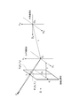
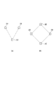
- Camera coordinate system shown in FIG. 2 is a Cartesian coordinate system, the origin is O C.
- the X axis, Y axis, and Z axis of the camera coordinate system are represented by an X C axis, a Y C axis, and a Z C axis, respectively.
- This pinhole model it is assumed that the origin O C is pinhole position, Z C axis is the optical axis of the camera, the imaging surface is present from the origin to the position of the focal length f.
- X axis of the imaging coordinate system is represented by X I-axis
- Y-axis is represented by Y I-axis.
- X I-axis and Y I-axis of the imaging coordinate system respectively parallel to the X C-axis and Y C axis of the camera coordinate system.
- an imaging target P in a three-dimensional space captured by a camera is an intersection point P u (X u , Y) between a straight line PO C connecting the imaging target P and the origin O C of the camera coordinates and the imaging surface.
- P u intersection point
- the position of P u corresponds to (X u , Y u ) in the imaging coordinate system.
- FIG. 3 shows the relationship of the coordinate system when two cameras are used.
- W is added as a subscript to the right shoulder of the symbol.
- the notation without W as a subscript is the notation of the right camera coordinate system or the left camera coordinate system.
- the origin O R of the right camera coordinate system in FIG. 2 is represented by the following equation (7) using the origin O R W of the right camera coordinate system in the world coordinate system.
- R R is the rotation matrix when converting from the world coordinate system in the right camera coordinate system.
- T R is a translation vector in the case of converting from the world coordinate system in the right camera coordinate system.
- P Ru of the projection point can be converted into the world coordinate system by the following equation (8).
- the first term and the second term of the equation (14) are vectors t R and t from the world coordinate system origin to the camera coordinate system origin in FIG. 3, respectively. This corresponds to L , and Expressions (15) and (16) are established.
- equation (14) can be expressed as the following equation (17).
- the pupil detection method according to the present embodiment includes a first step of capturing a first image by capturing a face of the subject with a first camera, and a second image by capturing the face of the subject with a second camera. A second step of acquiring, a third step of extracting one or more candidate points in the first image that are candidates for the subject's pupil from the first image, and a step of extracting the pupil of the subject from the second image.
- the third step of extracting the first image candidate points from the first image as described in Patent Documents 1 to 5, for example, pixels of the bright pupil image and the dark pupil image are used as the first image.
- the difference image obtained by calculating the difference between the values a point having a large pixel value in the difference image can be used as a candidate point in the first image.
- the third step may be executed by other methods.
- the first image it can be a candidate for a pupil based on image characteristics such as size and brightness peculiar to the pupil. What is necessary is just to extract a point.
- stereo matching used in the following explanation.
- the three-dimensional coordinates of the shooting target point are obtained by two cameras that have been subjected to camera calibration, which point in the image shot by each camera corresponds to the shooting target point is determined for each camera.
- the obtained point in the image is called an in-image candidate point.
- photographed with each of two cameras is matched mutually.
- the correspondence between the candidate points in the image by these two cameras is defined as stereo matching. Therefore, when all the candidate points in the image obtained by the two cameras correspond to the same shooting target point, the stereo matching is correctly performed.
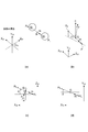
- FIG. 4 is a simplified diagram of FIG. Here, it is assumed that all are expressed in the world coordinate system. Now, the position of P L of the object caught on the respective left and right cameras, P When R, vector O L P L toward them from the origin of each camera, O R P R in the same direction of the vector O L P Lu, O R P Ru is obtained.
- the normal vector n L of the triangle O L P L O R is obtained by the outer product of the vector O L P Lu obtained by the equation (11) and the vector O L W O R W obtained by the equation (17). 19).
- This first method is particularly effective because it has high sensitivity with respect to the deviation between P L and P R about an axis about a straight line connecting two cameras.
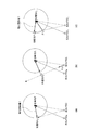
- FIGS. 5 (a) and 5 (b) An example is shown in FIGS. 5 (a) and 5 (b).
- the plane O L P L O R and the plane O L P R O R are parallel.
- not a P L P R. Therefore, if the camera horizontally aligned, but the deviation in the vertical direction of the P L and P R can be detected, the deviation of the P L and P R in the lateral direction can not be detected.
- the deviation in the horizontal direction as a result of the stereo matching P L and P R are reflected in a shift in the depth direction (Z-direction).
- FIG. 6 shows the contents of FIG. 5 in another expression.
- 6A corresponds to FIG. 5A
- FIG. 6B corresponds to FIG. 5B.
- Figure 5 (a) and FIG. 6 (a) and detects the left pupil P L in the left camera 2A, a case that detects the right pupil P R in the right camera 2B. If these are stereo-matched, the calculated three-dimensional coordinates of the target should be erroneously detected far behind the subject's face.
- FIGS. 5 (b) and. 6 (b) and detects the right pupil P R in the left camera 2A, a case that detects the left pupil P L at right camera 2B. In this case, the calculated target three-dimensional image should be erroneously detected ahead of the face. However, it is not possible to detect this shift in the coordinate in the depth direction only by the first method described above.
- the above-described first method is easy to calculate after obtaining the coordinates in the target imaging coordinate system in the image. Therefore, when there are a large number of candidate points in the image detected by the left camera 2A and the right camera 2B, the first method described above is effective for excluding candidate points in the image that do not correspond to the pupil of the subject. Is the method.
- the numbers of candidate points in the image obtained by the left and right cameras are N L and N R , respectively. These candidate points in the image are combined in a round robin manner to perform a series of operations of the first method described above. There are N L ⁇ N R combinations. Of these, combinations of candidate points in the image that are determined not to have been taken as a result of the calculation are excluded. Then, the coordinates of the candidate points in the image in the combination that remains without being excluded are stored as the coordinates on the images of both cameras as effective candidate points.
- a method for obtaining the three-dimensional coordinates of the photographing target point from the coordinates of the candidate points in the image obtained by stereo matching after stereo matching is as follows.
- This method is a method (three-dimensional reconstruction) that is obtained using a rotation matrix R and a translation vector T (formula (2)) calculated by Tsai camera calibration.
- R and T are expressed by the following formulas (22) and (23), respectively.
- the three-dimensional coordinates of the target candidate point are specifically obtained.
- the first method even if there is a mistake in the combination of candidate points in the images of the left and right cameras, this wrong combination may not be excluded.
- the three-dimensional coordinates of the target point are obtained from such an incorrect combination by the second method, it is determined whether the distance in the depth direction from the target camera to be obtained is within an appropriate range, that is, the Z coordinate.
- the Z coordinate By determining whether or not is in an appropriate range, it is possible to determine the case where the left and right pupils are mistaken as shown in FIG.
- a range in which the pupil of the subject exists may be given as a threshold as shown in Expression (27).
- the orientation of the two cameras is their the optical axes intersect at an appropriate single point is desired, the intersection and S, the positions of the two cameras O R, when the O L, O R and the axis connecting the midpoints and S of O L defines an orthogonal coordinate system with the Z axis, obtains the coordinates of M in the coordinate system, it may be applied to equation (27).
- the spectacle reflection is a reflection image, so it does not exist at one point in the three-dimensional space. Therefore, generally, when viewed from two cameras, the same shooting target point does not exist, and it looks like an object at a different point. For this reason, when the second method is executed when the spectacle reflection is a candidate point in the image and the three-dimensional coordinates of the target point are calculated, the value of the Z coordinate is not within the proper range, and the spectacle reflection is not in the pupil. I understand that there is no. Therefore, if the calculated three-dimensional coordinate value is not within the predetermined appropriate range, the selected candidate point in the first image and the candidate point in the second image correspond to the same point in the three-dimensional coordinate. You can exclude it as something you do not want.
- the first method was effective in detecting a stereo matching error in the direction around the axis about the straight line connecting the two cameras.
- the spectacle reflection often appears in the immediate vicinity of the pupil, so that strictness is required.
- the magnitude of the deviation is expressed as an angle around the axis, and the distance from the above-mentioned axis to the subject's face cannot be considered.
- the threshold value should be changed according to the distance from the axis, but the distance in the Z-axis direction is not obtained in the first method. So it can't.
- the third method not only the distance in the Z-axis direction obtained by the second method but also the distance between target candidate points obtained by each camera at that distance is known. Using this, it is determined whether or not stereo matching is correct. Next, a calculation method will be described.
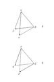
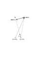
- FIG. 7 there are two cameras.
- the cameras are installed at the points O 1 and O 2 .
- the target candidate point P 1 is photographed with the camera at the point O 1
- the target candidate point P 2 is photographed with the camera at the point O 2 .
- a straight line connecting the point O 1 and the target candidate point P 1 is defined as g 1 (first straight line)
- a straight line connecting the point O 2 and the target candidate point P 2 is defined as g 2 (second straight line).
- the point (a 1 , b 1 , c 1 ) is not only a point on the common perpendicular but also a point on the straight line g 1 , and this point is H 1 .
- Expression (28) is set to t
- Expression (31) is established.
- Expression (31) When Expression (31) is substituted into Expression (30), Expression (30) can be expressed as the following Expression (32).
- becomes a small value, and the Z coordinate of the midpoint M also falls within the range where the subject exists. Therefore, it is possible to determine whether or not the target candidate points P 1 and P 2 are pupils by this third method. Specifically, the calculated
- the first method in the description of the first method, when arranged camera horizontally, but displaced in the vertical direction of the P L and P R can be detected, the deviation in the lateral direction of the P L and P R However, this problem is also present in the third method.
- a pair of two candidate points in space is selected from the extracted candidate points in space, and an operation for calculating a distance between the two selected pairs of candidate points in space is performed.
- a method of executing a seventh step performed on a pair of candidate points in space and an eighth step of excluding a pair of candidate points in space where the calculated distance between the pair of candidate points is not within a predetermined range explain. In this specification, this method may be referred to as a fourth method.
- the primary purpose of the first to third methods for executing the fifth and sixth steps described so far is to determine whether stereo matching is correct for each candidate point in the image. Then, in order to ensure that the in-space candidate points calculated from the in-image candidate points selected by the two cameras are really points where the subject's pupil was photographed, The pair of candidate points is paired, and by determining whether the distance between the paired candidate points in the space is a value within a reasonable range as the distance between human pupils, Determine if it is a pupil pair. Further, this method is effective for detecting pupil pairs of individual subjects or distinguishing individual subjects when two or more subjects are photographed.
- a pair of candidate points in space in which the calculated distance l is an invalid value as a human interpupillary distance is not a pupil pair, and the pupil pair (both pupil candidates) is excluded from the pupil pair candidates.
- a pair of candidate points in space with an appropriate distance l is determined to be a true pupil pair, and a pupil candidate forming the pupil pair is determined to be a pupil.
- the distance between human pupils is about 65 mm. Therefore, in consideration of changes in distance between pupils due to individual differences and convergence, an appropriate range for the distance l may be a predetermined range including 65 mm. For example, when the distance l is not 55 mm to 70 mm, the selected pair of in-space candidate points can be excluded from the pupil pair candidate as not being a true pupil pair.
- the candidate points in the space are determined based on human behavior characteristics, for example. It may be determined that For example, it is assumed that a straight line connecting two pupils is not greatly inclined with respect to the horizontal plane due to a person's large neck and the angle formed by a straight line connecting a pair of candidate points in space with respect to the horizontal plane A pair having a small value may be determined as a pupil pair. Moreover, you may make it select the thing with a magnitude
- the experimental environment and method are as follows. An experiment was performed in a room with a fluorescent lamp, with a subject wearing spectacles sitting at a position approximately 80 cm away from the camera and irradiating the subject's face with light from a light bulb. The reason for performing the irradiation with the light bulb is to reduce the pupil so that it has a size close to the spectacle reflection, so that erroneous detection is likely to occur. The illuminance in the vicinity of the subject's eyes was 366 to 751 lx.
- the subject's head is not fixed in particular, and the eye is instructed to open and close several times for 300 frames, and an image is taken during that time, and the pupil is detected by the conventional pupil detection method and the pupil detection method of the present embodiment. Detection was performed.
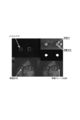
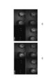
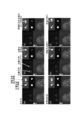
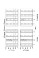
- FIG. 9 is a photograph showing the image taken in this experiment and the results of various processing performed on the image. 9 is roughly divided into a lower left part, a lower right part, an upper left part, and an upper right part, and the upper right part is divided into an upper half and a lower half.
- the lower left part of FIG. 9 is a bright pupil image in which the pupil of the subject is projected brightly.
- the lower right portion of FIG. 9 is a dark pupil image in which the subject's pupil is darkly projected.
- the upper left part of FIG. 9 is a difference image created by taking the difference between the pixel values of the bright pupil image and the dark pupil image.
- the upper half of the upper right part of FIG. 9 is a bright pupil image obtained by enlarging the pupil portion of the subject and increasing the resolution.
- the lower half of the upper right part of FIG. 9 is an image obtained by binarizing the high-resolution bright pupil image of the upper half of the upper right part of FIG.
- FIG. 10 FIG. 11 and FIG. 26 below, the respective images are similarly arranged.
- the bright pupil image in the lower left part and the dark pupil image in the lower right part of FIG. 9 are spectacle reflections that are reflections of light reflected by the spectacle lens and reflections of light reflected by the spectacle frame.
- the spectacle frame reflection is reflected. These spectacle reflections are almost eliminated to some extent in the difference image. Further, since the brightness of the pupil of the subject is greatly different between the bright pupil image and the dark pupil image, the portion corresponding to the pupil of the subject is bright in the difference image in the upper left part of FIG.
- the image processing apparatus 1 detects the presence of a pupil in this portion based on image characteristics such as brightness and size of the brightened portion, and displays a small window (small region) on the pupil portion. ing.
- This small window is used to estimate the position of the pupil and limit the target region for searching the pupil when performing pupil tracking processing described later.
- the image processing apparatus 1 performs pupil tracking processing by searching for a figure that is considered to be a pupil within this small window.
- a substantially circular figure is displayed at a position overlapping the bright pupil of the subject.
- this square shows corneal reflection that is a reflection image of light by the cornea of the subject. The corneal reflection detection process will be described later.
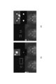
- FIG. 10 is a processed image when the subject closes his eyes.
- FIG. 10A is a processed image by the conventional pupil detection method
- FIG. 10B is a processed image by the method of the present embodiment.
- the spectacle reflection by the right eye lens portion of the spectacles remains as a white point in the difference image.
- FIG. 10A a white point due to this spectacle reflection is erroneously detected as a pupil, and a small square is displayed in this portion.
- FIG.10 (b) the white point by spectacles reflection is not detected as a pupil, but is not detected.
- FIG. 11 is a processed image immediately after the subject opens his eyes at a time later than FIG.
- FIG. 11A is a processed image by the conventional pupil detection method
- FIG. 11B is a processed image by the method of the present embodiment.
- the spectacle reflection is erroneously detected as a pupil.
- the pupil that can be photographed by the camera can be correctly detected when the subject opens his eyes.
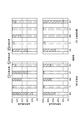
- FIG. 12 is a diagram showing the pupil detection rate of the left camera when the subject's eye is closed.
- FIG. 12A shows the pupil detection rate according to the conventional pupil detection method.
- FIG. 12B shows the pupil detection rate according to the pupil detection method of the present embodiment. Both FIG. 12A and FIG. 12B show the detection rates of the left and right pupils when five subjects are subjects.
- the positive detection rate indicates a ratio when the pupil is correctly detected.
- the non-detection rate indicates a ratio when the position of the pupil is not detected.
- the false detection rate indicates a ratio when an object other than the pupil, for example, spectacle reflection is erroneously detected as being a pupil.
- the glasses reflection is tracked while misrecognizing the erroneously detected glasses reflection as a pupil, Since it becomes impossible to detect the pupil for a long time, it is not preferable to perform erroneous detection.
- the correct detection rate is preferably 0%, the non-detection rate is 100%, and the false detection rate is preferably 0%.
- the correct detection rate is preferably 0%, the non-detection rate is 100%, and the false detection rate is preferably 0%.
- the conventional pupil detection method shown in FIG. 12A erroneous detection occurs in many subjects.
- FIG.12 (b) no false detection has arisen in all the test subjects.
- the pupil detection rate is almost the same as that in the left camera.
- FIG. 13 is a diagram showing the pupil detection rate of the left camera when the subject's eyes are open.
- FIG. 13A shows the pupil detection rate according to the conventional pupil detection method.
- FIG. 13B shows the pupil detection rate according to the pupil detection method of the present embodiment.
- FIG. 14A shows an image taken by the left camera.
- FIG. 14B shows an image taken with the right camera. Both FIG. 14A and FIG. 14B are composed of four images.
- the lower left image is a bright pupil image acquired by photographing the subject.
- the lower right image is a dark pupil image acquired by photographing the subject.
- the upper left image is a difference image generated by subtracting the pixel values of the bright pupil image and the dark pupil image. In the upper left image, a white cross-shaped figure indicates the position of the pupil detected by the pupil detection process.
- the upper right image shows the result of detecting the left and right pupil pairs of the same person.
- a white cross-shaped figure indicates the position of the pupil detected by the pupil detection process.
- a white straight line connecting white cross-shaped figures connects points detected as the left and right pupil pairs of the same person.
- the process using the shortest distance between two straight lines in the first method and the third method is performed to extract candidate points in the space, and further according to the distance between the two points.
- the process of selecting candidate points in space is executed in order to determine the subject's pupil pair. In this case, either the first method or the third method may be omitted.
- FIG. 15 is a diagram schematically showing an apparatus for executing the corneal reflection detection method according to the present embodiment and the eyeball of the subject.
- this corneal reflection detection method the left camera 2A, the right camera 2B, and the light source 3 (3a, 3c) are used.
- the above-described pupil detection method is executed using the left camera 2A and the right camera 2B in advance, and the three-dimensional coordinates of the pupil are detected.
- description will be made on a case-by-case basis according to the positions of the left camera 2A, the right camera 2B, and the light source 3 (3a, 3c).
- the light source 3a is provided in the vicinity of the camera 2A.
- a light source 3c is provided in the vicinity of the camera 2B.
- the first image is acquired by the left camera 2A while irradiating the eyeball with the light source 3a. Further, the second image is acquired by the right camera 2B while irradiating the eyeball with the light source 3c. If it does in this way, the corneal reflection in which the light of the light source 3a was reflected by the cornea will be reflected in the 1st image, and the corneal reflection in which the light of the light source 3c was reflected by the cornea will be reflected in the 2nd image.
- the shape of the cornea is a spherical shape called a corneal sphere. For this reason, the corneal reflection reflected in each of the first image and the second image appears to be emitted from the light source at the center of the corneal sphere.
- one or more first intracorneal reflection candidate points that are candidates for corneal reflection of the subject are extracted from the first image
- one or more second points that are candidates for corneal reflection of the subject are extracted from the second image. Extracting the corneal reflection candidate point in the image, selecting one point from each of the first and second corneal reflection candidate points in the image, and using the coordinates in the image of the selected point, When the three-dimensional coordinates are calculated by using the third method, it can be obtained as if the light source is located at the center of the corneal sphere.
- the obtained three-dimensional coordinates of the corneal reflection candidate are within a predetermined range with respect to the previously detected three-dimensional coordinates of the pupil, for example, a range of several mm. If it is within, the determined corneal reflection candidate is determined to be a true corneal reflection.
- the arrangement of the light source 3a and the light source 3b is the same as in the case of FIG.
- the light source used at the time of shooting is different from that in FIG. That is, the first image is acquired by the left camera 2A while irradiating the eyeball with the light source 3c, and the second image is acquired by the right camera 2B while irradiating the eyeball with the light source 3a.
- three-dimensional coordinates that are candidates for corneal reflection are obtained in the same manner as in FIG.
- the obtained three-dimensional coordinates are on the surface of the corneal sphere.
- the distance between the three-dimensional coordinates of the corneal reflection candidate and the three-dimensional coordinates of the pupil is within a range of several millimeters, it can be determined that the obtained corneal reflection candidate is a true corneal reflection.
- one light source 3 is used instead of the light source 3a and the light source 3b. Then, both when the first image is acquired by the left camera 2A and when the second image is acquired by the right camera 2B, the eyeball of the subject is irradiated by the light source 3. In this case, the required position of corneal reflection differs depending on the position of the light source 3. However, in any case, when the distance between the three-dimensional coordinate of the corneal reflection candidate and the three-dimensional coordinate of the pupil is within a range of several mm, it is determined that the obtained corneal reflection candidate is a true corneal reflection. Can do.
- both the left camera 2A and the right camera 2B can detect the candidate points in the pupil image.
- the pupil cannot be detected as an in-image candidate point in the image taken with the camera, and the first to fourth methods described above are used. May not be implemented successfully. Therefore, it is more preferable to use three or more cameras. When three cameras are used, even if a candidate point in the image of the pupil cannot be detected from an image captured by one of the cameras, the pupil is captured using images captured by the other two cameras. If the candidate points in the image are detected, the first to fourth methods described above can be executed, so that pupil detection can be performed more reliably.
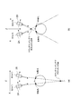
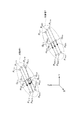
- FIG. 16 shows an example of the arrangement of three or more cameras.
- FIG. 16A shows an example of the arrangement of three cameras 2A to 2C.
- the third camera 2C is preferably arranged at a position away from a straight line connecting the first camera 2A and the second camera 2B.
- the first method or the third method described above when two different points located on a plane including this axis are photographed by different cameras with the straight line connecting the two cameras as the axis It was difficult to exclude.
- the first camera 2A and the second camera 2B are arranged side by side in the horizontal direction, the first camera 2A and the second camera 2B each detected two different points separated in the horizontal plane as candidate points in the image. In this case, it is difficult to exclude such a set of candidate points in the image.
- the three cameras 2A to 2C are preferably arranged at the positions of the vertices of the equilateral triangle. In particular, when considering the problem of spectacle reflection and pupil overlapping in the image, it is preferable that the three cameras 2A to 2C be installed at an angle of at least about 10 degrees as viewed from the subject.
- FIG. 16 (b) shows an example of the arrangement of four cameras 2A to 2D.
- the third camera 2C and the fourth camera 2D are preferably arranged at positions away from a straight line connecting the first camera 2A and the second camera 2B. More preferably, the cameras 2A to 2D are arranged at the positions of the four vertices of the rectangle. In particular, it is more preferable to arrange the cameras 2A to 2D at the positions of the four vertices of the square.
- one pupil detection result is obtained for each set of two cameras. Therefore, one pupil detection result may be obtained by performing an operation such as calculating an arithmetic average of coordinate values on the pupil detection result for each set of cameras.
- the position of the subject's pupil pair can be obtained more accurately as follows.
- Three cameras are designated as cameras 1 to 3.
- a combination of two cameras (camera pair) is determined.
- three camera pairs are obtained.
- a combination of the camera 1 and the camera 2 is a camera pair 1-2
- a combination of the camera 2 and the camera 3 is a camera pair 2-3
- a combination of the camera 3 and the camera 1 is a camera pair 3-1.
- the number of cameras used is not limited to three, but may be at least three.
- the number of camera pairs is not limited to three, and at least three sets may be determined.
- first, pupil pair candidates are determined for each camera pair. Specifically, for each of the determined at least three camera pairs, one camera of the camera pair is a first camera, the other camera of the camera pair is a second camera, and the first to ninth described above are used.
- a pair of pupils of the subject is determined as a candidate pupil pair by a pupil detection method including steps. More specifically, a candidate point in the space is acquired, and the candidate method in the space where the angle ⁇ (see Equation (20)) satisfies Equation (21) is left by the first method. By the method 3, the three-dimensional coordinates of the candidate points in space are calculated.
- the fourth method it is determined that a pair of two candidate points in the space in which the distance between the two candidate points in the space becomes an invalid value as a human interpupillary distance is not the target pupil pair. And exclude it.
- the space candidate point pairs that remain without being excluded are left as candidates for the subject's pupil pairs.
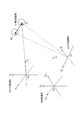
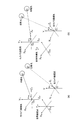
- the left eye pupil candidate P L112 of the subject 1 is detected by the camera pair 1-2. 1 of the right eye pupil candidate P R112, subject 2 of the left eye pupil candidate P L212, a right eye pupil candidates P R212 subjects 2 was required. Further, by the camera pair 2-3, the first pupil candidate P L123 of the left eye of the subject 1, the second pupil candidate R 123 of the left eye of the subject 1, the pupil candidate PR 123 of the right eye of the subject 1, the subject 2 left eye pupil candidate P L223, a right eye pupil candidates P R223 subjects 2 was required.
- R231 is obtained.
- the second pupil candidate R 123 of the left eye of the subject 1 obtained by the camera pair 2-3 is actually a spectacle reflection image of the subject 1 and is different from the actual pupil of the subject 1.
- Each other pupil candidate corresponds to the pupil of the actual subject 1.
- a vector direction vector connecting both pupils (that is, one and the other of the pupil pair candidates) and the midpoint of both pupils are obtained.
- the direction vector of the vector connecting the pupil candidate P L112, P R112 is m 112
- the midpoint is G 112.
- Direction vector of the vector connecting the pupil candidate P L123, P R123 is m 123
- the midpoint is G 123.
- the direction vector of the vector connecting the pupil candidates R 123 and PR 123 is m E123
- the middle point is G E123 .
- the direction vector of the vector connecting the pupil candidates P L131 and PR 131 is m 131 and the midpoint is G 131 .
- Direction vector of the vector connecting the pupil candidate P L212, P R212 is m 212, the midpoint is G 212.
- the direction vector of the vector connecting the pupil candidates P L223 and PR 223 is m 223 and the midpoint is G 223 .
- Direction vector of the vector connecting the pupil candidate P L231, P R231 is m 231, the midpoint is G 231.
- the direction vectors obtained by each of the three camera pairs have a property that the angle between them is almost zero. Further, the midpoint obtained by each of the three camera pairs has a property of being in a position close to each other. By utilizing such a property, it is possible to distinguish which pupil pair candidate corresponds to which subject's pupil for a plurality of subject's pupil pairs, and to detect erroneously detected pupil candidates. It can be eliminated and the correct pupil pair can be obtained. That is, the direction vector direction determined for the candidate pupil pair determined by one camera pair is equal to the direction vector direction determined for the candidate pupil pair determined by other camera pairs and a predetermined threshold value. When the above angles are formed, the candidate pupil pair determined by the one camera pair is removed.
- the midpoint G 112, G 123, G 131 , G E123 is in close position.
- Midpoint G 212, G 223, G 231 is at a position close to each other, and in a position far from the center point G 112, G 123, G 131 , G E123.
- the midpoints G 112 , G 123 , G 131 , and G E123 are the midpoints of a pair of pupil candidates of one subject (ie, subject 1)
- the midpoints G 212 , G 223 , G 231 Can be determined to be the midpoint of a pair of pupil candidates of another subject (ie, subject 2).
- the direction vector m E123 has a large angle with the direction vectors m 112 , m 123 , and m 131 . Thereby, it can be determined that the pupil candidate R 123 used for obtaining the direction vector m E123 does not correspond to the true pupil of the subject.
- the average value of the coordinates of the candidate pupil pairs that remain without being removed depending on the direction of the direction vector is taken, and this average value is determined as the final pupil position, thereby further increasing the pupil position. It can be estimated correctly. Specifically, when three cameras are used, for example, two camera pairs are selected that are closer to the midpoint and have a smaller angle formed by the direction vectors, and are included in the selected camera pair. By taking the average value of the coordinates of the pupil candidates obtained based on the two cameras and determining this average value as the final pupil position, the pupil position can be correctly estimated. After correctly estimating the position of the pupil in this way, by projecting the estimated position of the pupil onto the camera image, a window for limiting the target area for searching the pupil can be given during pupil tracking. it can.
- the pupil positions detected by different camera pairs are shifted due to errors in camera calibration (stereo calibration).
- the directions of the straight lines connecting the pupil candidates obtained by different camera pairs that is, the direction of the direction vector
- the spectacle reflection image is erroneously detected as a pupil candidate
- the direction of the straight line connecting the pupil pair including the spectacle reflection that is, the direction of the direction vector
- the spectacle reflection image overlaps the pupil image with one of the three cameras, and thus the pupil may not be detected.
- a pupil pair can be obtained only in one camera pair including two cameras excluding the one camera. Therefore, since only one pair of pupil pairs can be obtained, a method of selecting the correct pupil pair using the midpoint of the pupil pair obtained by the above-described three camera pairs and the direction vector connecting the pupil pair cannot be used. For this reason, when it is assumed that the spectacle reflection image and the pupil image overlap with each other, it is desirable that the number of cameras be at least four.
- the distance between the pupil candidate points remaining after the processing up to the previous stage is calculated as a brute force.
- the pupil candidate points whose calculated distance is equal to or less than a predetermined threshold are grouped so as to form one group.
- the predetermined threshold value can be arbitrarily determined according to the accuracy of stereo calibration by each camera pair, but needs to be smaller than a value that can be a human pupillary distance.
- the predetermined threshold may be 4.5 cm, for example.
- candidate points due to erroneous detection of spectacle reflection images and the like cannot be removed, and candidate points due to erroneous detection may be included in any group.
- candidate points due to false detection are excluded by a method using the above-described inter-pupil distance and inter-pupil direction vector (and the inter-pupil midpoint may also be used).
- the pupil pair is detected.
- the object of the calculation to calculate the distance between the candidate points, the direction vector connecting the candidate points, and the midpoint between the candidate points can be greatly reduced.
- the number of cameras is three or more and the stereo calibration of each camera pair can be performed accurately, erroneous detection of spectacle reflection can be minimized by the process up to the previous stage. For this reason, it is possible to independently detect one pupil rather than a pupil pair by grouping.
- the following method is used to track two pupils as one lump, with the constraint that the distance between the three-dimensional pupils of both eyes of the subject is constant. Now, let the three-dimensional interpupillary distance be l, and let l be known. However, in practice, once the pupil detection process is performed and the three-dimensional coordinates of both pupils are detected, l can be determined based on the detected three-dimensional coordinates of the pupil. In the subsequent pupil tracking process, the value of l determined in this way may be used.
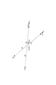
- FIG. 18 shows a state in which two pupils are moved by moving the user's head while a plurality of cameras that have undergone camera calibration are arranged.
- 3-dimensional coordinates of the left pupil P L and the right pupil P R is generally determined by stereo matching in two or more cameras which were camera calibration, the left pupil obtained P L and the right pupil P R 3
- the following pupil tracking processing is performed based on the dimensional coordinates.
- Figure 18 shows only two cameras, respectively and the left camera and the right camera, shows the left camera coordinate system to the point O L the origin, the right camera coordinate system to the point O R as the origin Yes.
- both pupil centroids G and the inter-pupil unit direction vector m are expressed by the following equations (45) and (46).
- the absolute position and relative position of the pair of pupils can be obtained from the pupil center of gravity G, the inter-pupil unit direction vector m, and the inter-pupil distance l.
- Both the pupil center of gravity G and pupillary unit direction vector m are each composed of three elements ((G x, G y, G z) and (m x, m y, m z)).
- a prediction model represented by the following equations (47) and (48) is applied to each of these six elements. Here, it is assumed that each element changes at a constant speed.
- ⁇ T represents the time between frames
- t represents the time of the current frame
- t-1 represents the previous frame
- t-2 represents the second previous frame.
- a Kalman filter may be used as the prediction model. If it is assumed that an image is missed or an image is acquired irregularly, the following method is effective. If it is assumed that the time (actual time) 2 frames before and 1 frame before is t ⁇ 2 and t ⁇ 1 and the current frame time is t 0 , each element changes at a constant speed. For example, the following equation holds.
- Equation (49) the value of each element at the current time is given by the following Equation (50).
- the unit direction vector m it is more appropriate to assume that m rotates in a constant direction at a constant speed, rather than each element independently changing at a constant speed. . That is, it is assumed that the unit direction vectors m two frames before and one frame before are m (t ⁇ 2 ) and m (t ⁇ 1 ), respectively, and they rotate on the same plane. m (t -2) and m (t -1) the inner product of m (t -2) and m (t -1) the angle ⁇ is seen in.
- Direction of rotation of the code ie m angle ⁇ is the Cartesian coordinate system the plane containing both the the x-y plane of the m (t -2) and m (t -1), m and (t -2) m ( It can be seen from the sign of the z coordinate of the outer product of t ⁇ 1 ). Therefore, m (t 0 ), which is m in the current frame, is assumed to have a rotational angular velocity ⁇ (t ⁇ 1 ) from m (t ⁇ 2 ) to m (t ⁇ 1 ) assuming constant rotation of m. It can be obtained by a condition (following equation (51)) that coincides with the rotational angular velocity ⁇ (t 0 ) from m (t ⁇ 1 ) to m (t 0 ).
- the pupil center of gravity G and the inter-pupil unit direction vector m of the current frame are predicted from G and the vector m two frames before and one frame before (G ′, m ′ and deep).
- the expressions (49) and (50) may be used instead of the expressions (47) and (48), and the expression (51) is used. May be.
- the three-dimensional coordinates P ′ L and P ′ R of the left and right pupils in the current frame are expressed by the following equations (52) and (53). Ask.
- the in-image coordinates of the pupil can be obtained by projecting the obtained three-dimensional coordinates of the pupil onto the camera image plane.
- the difference is obtained after shifting the image of the pupil part one frame before (the image in the small window) to the estimated position of the current frame.
- the interpupillary distance l given by the equations (52) and (53) is not actually constant, and the interpupillary distance l may slightly change if the accuracy of camera calibration is low. For this reason, l may be predicted from the inter-pupil distance of the previous frame by using the prediction models of Expressions (47) and (48), and Expressions (54) and (55) may be used. Note that for the prediction of the interpupillary distance l, the prediction models of the equations (49) and (50) may be used instead of the prediction models of the equations (47) and (48), or the equation (51) A prediction model may be used.
- the movement amount of corneal reflection described in Patent Document 8 is used. It is preferable to perform the differential position correction method.
- the difference position using the movement amount of corneal reflection described in Patent Document 8 It is preferable to perform the correction method.
- the corneal reflection does not always exist depending on the angle of the line of sight. Therefore, when the corneal reflection does not exist, the difference position correction is performed by the difference position correction method using the interpupillary distance as it is. As described above, when the two-dimensional coordinates of the pupil are obtained from the images of the respective cameras, the three-dimensional coordinates of the pupil in the current frame are obtained by stereo matching, and the rest is repeated.
- the corneal reflection detection method has already been described with reference to FIG. 15, but here, another method for detecting corneal reflection will be described.
- 15A to 15D if the three-dimensional coordinates of the corneal reflection obtained from the two cameras are true three-dimensional coordinates of the corneal reflection, the two left and right of the subject Similar to the distance between the two pupils, the corneal reflection distance is almost always a constant value. Therefore, corneal reflection can also be detected using a method similar to the pupil detection method of the present embodiment.
- the specific procedure is as follows. First, the subject's face is photographed by the left and right cameras to obtain an image. Next, an intra-corneal reflection candidate point that is a candidate for corneal reflection of the subject is extracted from the acquired image. At this time, in general, when the pupil cannot be detected due to closed eyes or the like, corneal reflection cannot usually be detected, so it is more efficient to extract corneal reflection candidate points from a small window (small region) centered on the already detected pupil. It is. In addition, image corneal reflection candidate points are selected and combined one by one from the images acquired by the left and right cameras, and the combination is selected based on the above-described method for extracting candidate points in space and the distance between the two points. The three-dimensional position of the left and right corneal reflections of the subject is calculated by applying the method of selecting the inner candidate point.
- an image corresponding to a range of several mm from the center of the corneal sphere is assumed on the assumption that a pupil is present within a range of several mm from the corneal reflection.
- Set a small window (small area) in the area is set. Then, by performing a difference process within this small window, the position of the pupil is determined, and the intra-image coordinates of the pupil are calculated.
- two pupil pairs may be obtained.
- one is a pupil pair consisting of a real pupil of the left eye and a real pupil of the right eye, and the other is a reflection of the glasses near the real pupil of the left eye and the right eye).
- a small window is given to the candidate pupil points in the image constituting both pupil pairs, and a corneal reflection pair is obtained for the small window.
- corneal reflection a plurality of pairs may be obtained. At that time, in each of the left eye and the right eye, the obtained corneal reflection pair candidate and the pupil constituting the pupil pair candidate and those having the closest three-dimensional distance between the corneal reflection are judged as the real pupil and the real corneal reflection. To do.
- the method described above is used.
- the three-dimensional position of the pupil of the current frame is estimated using the equations (45) to (53) from both pupil centroids G and the inter-pupil unit direction vector m that have already been clarified.
- the pupil position of each pupil in the image of the current frame is estimated.
- the two-dimensional positions of the two pupils are calculated after shifting the image around the pupil position (in the small window) in the previous frame that has already been calculated to the estimated pupil position in the current frame image. Is calculated.
- the pupil detection in the image and the three-dimensional position of the pupil are calculated. Further, the center of gravity G of both pupils and the unit direction vector m between the pupils are obtained from them, and the three-dimensional positions of the left and right pupils are recalculated by the equations (52) and (53) or the equations (54) and (55). To do. In the next frame, these pieces of information are used as the left and right pupil three-dimensional positions, the pupil center of gravity G, and the inter-pupil unit direction vector m in the previous frame. In this way, when both of the two pupils can be detected by both of the two cameras, the positional information of both pupils is handled equally.
- the left pupil P L can be detected by both cameras, it is assumed that the specific image on the right camera image and the specific image on the left camera image are P L , and the left pupil is obtained by stereo matching. and calculates the three-dimensional position of the P L. In contrast, since the right camera O R A right pupil P R is not detected, the three-dimensional position of the P R is unknown. However, since the right pupil P R in the left camera O L is able to detect, right pupil P R will be present on the straight line O L P R. Therefore, the condition that the right pupil P R is present on the straight line O L P R, the three-dimensional position of P R and a condition that is equal to the three-dimensional distance l between the length of the line segment P L P R is the pupil calculate.
- the camera O L (x 0, y 0 , z 0) and the right pupil P equation of the straight line O L P R connecting the R is, O L unit toward the P R from the direction vector u LR (u x , u y , u z ) is given by the following equation (57).
- Expression (58) When the value of Expression (57) is a parameter t and the values of x, y, and z are expressed using the parameter t, the following Expression (58) is obtained.
- the first case is a case where there is one solution of equation (59), that is, a case where equation (59) has multiple solutions.
- the second case is a case where the solution of Equation (59) is two conjugate complex numbers.
- the third case is a case where the solution of equation (59) is two different real numbers.
- the distance between the straight lines O L P R and P L is the shortest when P L P R and the direction vector u LR of the straight line are orthogonal to each other.
- inner product of the L P R and the vector u LR is zero.
- the Motoma' was t into Equation (58) determining the 3-dimensional coordinates of P R. Further, when the Motoma' was t into equation (60), between the two pupils distance is the length of the vector P L P R
- l max is the maximum inter-pupil distance and is set in advance.
- Motoma' and P R was, sought P L and G which obtained from them, vectors m which are already Motoma', use these values in the next frame .
- the solution of equation (59) becomes a conjugate complex number
- the distance between the obtained left pupil P L and the right pupil P R becomes the previously obtained with both interpupillary distance l had different values .
- the left pupil P L and the right are again obtained using the equations (52) and (53) or the equations (54) and (55). calculate the pupil P R, they are used in the next frame.
- Equation (59) when the solution of equation (59) is two different real numbers, by substituting t obtained by equation (59) into equation (58), as a candidate for P R, two 3 dimensional coordinate is obtained (FIG. 21 (c) P R and P R in '). Therefore, it is necessary to estimate which of the two obtained candidates is the true right pupil. To determine which of the two candidates is the true right pupil position, which of the obtained candidates is predicted by Equation (52) and Equation (53) (or Equation (54) and Equation (52)). the distance to the three-dimensional pupil position of P R is determined whether closer in the current frame and determines who distance to the position of P R of the current frame of the two candidates is close to the real pupil position.
- right pupil P R is instead methods assume that on a sphere of radius l around the left pupil P L, right pupil P R is centered on the left pupil P L It may be calculated on the assumption that it is on a spherical surface of l min .
- l min is a minimum value that can be considered as an interpupillary distance that is smaller than a predetermined interpupillary distance l, and may be, for example, 75% of the initially measured interpupillary distance. Note that when a nearby object is viewed, the interpupillary distance approaches due to the convergent eye movement, so a certain allowable range is required for the interpupillary distance.
- look, and it right pupil P R is detected when less than l max. Then, G, seeking m, formula (52) and (53), or using Equation (55) Equation (54), again, to calculate the left pupil P L and the right pupil P R, Use them in the next frame.
- the three-dimensional position of the pupil detected by both cameras is first determined, and one camera is determined based on the position of the pupil detected by both cameras.
- the one detected by only is detected in a dependent manner. This is because it is considered that the reliability detected by only one camera is low in the three-dimensional position detected.
- the right camera O R showed a case in which can be detected only the left pupil P L. Both right camera O R and the left pupil P L and the right pupil P R and can detect, the left camera O L, even if able to detect only the right pupil P R, similarly, first, the right pupil P R determined the three-dimensional coordinates, then we obtain the 3-dimensional coordinates of the left pupil P L.
- each pupil can be detected by another camera. That is, when the left pupil can be detected by the left camera and the right pupil can be detected by the right camera as shown in FIG. 23A, or the right pupil and the right camera can be detected by the left camera as shown in FIG. Next, the case where the left pupil can be detected will be described.
- the left pupil as derived from the detected two-dimensional pupil position from the left camera image
- the straight line O L as the unit direction vector is u LL (third linear) present on the right pupil
- O R as a unit direction vector is present on a straight line (fourth straight line) is a u RR from the right camera image.
- a straight line connecting the left pupil P ′ L and the right pupil P ′ R in the current frame predicted by the equations (52) and (53) or the equations (54) and (55).
- O L as the unit direction vector to seek common perpendicular of the straight line is u LL.
- a Motoma' common vertical line, O L as the unit direction vector is to obtain the intersection of the straight line is u LL, seek Motoma' intersection as the three-dimensional coordinates of the left pupil P L. This obtained intersection is an approach point that approaches both the third straight line and the fifth straight line.
- a Motoma' common perpendicular, O R as a unit direction vector is to obtain the intersection of the straight line is u RR, seek Motoma' intersection as the three-dimensional coordinates of the right pupil P R.
- the obtained intersection is an approach point that approaches both the fourth line and the fifth line.
- Equation (52) and Equation (53) or Equation (54) and Equation (55) are used. and calculates the left pupil P L and the right pupil P R, they are used in the next frame. In this way, the state in which each pupil is detected by only one separate camera is generally unstable. If this state continues continuously, the three-dimensional coordinates of the pupil can be estimated correctly.
- l represents the interpupillary distance obtained in the previous frame.
- this experiment was performed using an apparatus similar to the pupil detection apparatus 10 shown in FIG. More specifically, this apparatus includes two sets of optical systems configured with a camera (stereo), a light emitting circuit, a personal computer, and the like.
- Each of the optical systems includes a non-interlaced digital camera, a 16 mm lens, a visible light cut filter, and a double ring near infrared LED light source.
- the acquired image of the camera was a 60 fps gray scale image, and the size of one frame was 640 ⁇ 480 pixels.
- the inner LED and the outer LED of the ring-shaped LED light source were alternately blinked by a strobe signal from the camera to obtain a bright pupil image and a dark pupil image, respectively, and a difference image was obtained therefrom.
- the synchronization between the two cameras was shifted by 650 microseconds so that the light emitted from one of the light sources did not interfere with the other camera.
- the experiment was performed in a situation where four spectacle wearers were seated at a position approximately 80 cm away from the camera and the subject's face was illuminated with a light bulb.
- the light bulb was used to make the subject's pupil smaller by making the subject feel dazzling rather than causing the eyeglass to reflect the eyeglass, thereby making it difficult to distinguish between the pupil and the eyeglass reflection.
- the illuminance around the pupil was 262 to 345 lx.
- the subject was shaken face left and right so that a time zone in which the pupil in the camera image overlaps with the eyeglass reflection, and 300 frames of the image were taken for each subject. In the analysis, the captured image was confirmed for each frame.
- FIG. 26 shows a processed image in the right camera of the conventional method and this embodiment when the face is moved to the left and right.
- FIGS. 26A to 26C are processed images according to the conventional method.
- FIGS. 26D to 26F are images processed by the pupil tracking method of this embodiment.
- the conventional method when the face of the subject moves from the state shown in (a) to the state shown in (c), if the pupil and the spectacle reflection overlap as shown in (b), it is not the pupil at the timing shown in (c). Tracking of spectacle reflexes began.
- tracking is performed for each of the left and right pupils for each of the left and right cameras, and the pupil position is detected by correcting the differential position of corneal reflection.
- FIG. 27 shows the left and right pupil detection rates in the right camera.
- the positive detection rate is a case where the pupil is correctly detected as a pupil
- a non-detection is a case where nothing is detected
- a false detection means that a portion other than the pupil is erroneously detected as a pupil.
- the positive detection rate was high even in the conventional method, and thus the pupil tracking method of the present embodiment was a difference that was closer to 100%.
- the false detection rate was very high in the conventional method, but according to the pupil tracking method of the present embodiment, as shown in the graph on the right side of FIG. The rate decreased to zero.
- the non-detection rate is large.
- the eyeglass reflection overlaps the pupil and is reflected in the camera. Therefore, it is appropriate that the non-detected frame is not detected. This can also be seen from the fact that the non-detection rate in the conventional method and the non-detection rate in the proposed method are almost the same value. Similar results were obtained for the left camera.
- This face posture detection method is a method for detecting the face posture of the subject based on the three-dimensional coordinates of the pair of pupils of the subject detected by the above-described pupil detection method.
- the left and right rotations of the subject's head and the rotation around the front and rear axes can be detected.
- the two pupils of the left pupil P L and the right pupil P R of one of the subject is present.
- the Y w axis of the world coordinate system and a vertical axis the positive direction of the Y w axis vertically upward. That is, it is assumed that the positive direction of the Yw axis is upward in the subject's standard head posture.
- Z w axis by longitudinal axis is an axis passing through the front and rear head of the subject, the positive direction is a direction toward the rear of the head of the subject.
- the broken line is a straight line parallel to the X w -Z w plane.
- the angle ⁇ in this figure indicates the inclination of the interpupillary unit direction vector m from the horizontal plane.
- the angle ⁇ can be expressed by the following equation (65) using the component of the vector m.
- the angle ⁇ in the horizontal direction of the face when the two pupils are viewed from above the head can be shown as in FIG.
- An arrow F in the figure indicates the front direction of the face.
- the angle ⁇ can be expressed by the following equation (66) using the component of the vector m.
- the rotation angle ⁇ of around longitudinal axis of the face as an angle as viewed from the front (the negative direction of Z w axis) in a standard head pose of the subject, it can show as in FIG. 28 (d).
- the angle ⁇ can be calculated by the following equation (67).
- both pupil centroids G as face positions, it is possible to detect a face posture excluding vertical rotation.
- the face orientation is detected using only the pupil position, and the nostril is not detected. Therefore, the face direction cannot be accurately detected.
- the camera is placed considerably below the front of the subject's face, the nostril often appears in the image, so the nostril is detected by image processing, and the method described in Patent Documents 3, 4, and 9,
- the face direction can also be detected using the position of the nostril. It is conceivable that the face posture detection method is switched between when the nostril is detected and when it is not detected.
- the difference position correction has been mainly described.
- the reflected light from the face of the light from the two-wavelength light source is wavelength-separated, and the acquisition timing of the bright pupil image and the dark pupil image is simultaneously performed. This eliminates the need for differential position correction. In such a case, the differential position correction is not necessary.
- the three-dimensional coordinates of the pupil of the current frame are obtained from the information obtained in the previous frame. Since it is predicted and converted into coordinates on the image on the current frame of each camera, it is possible to provide a small window centered on it in the same manner as the method of the present invention.
- the advantage of tracking is that it is difficult to distinguish left and right pupils in pupil detection.
- the right wink operation and the left wink operation of the subject have been made to correspond to the right click operation and the left click operation in a mouse operated by a general hand.
- the right and left pupils are identified, and if one of them is not detected after that, is the pupil that continues to be detected the right pupil? Whether it is a left pupil was identified from the continuity accompanying tracking. If tracking is not performed and the pupil is detected from the entire image for each frame, there is no correlation between frames, so in a frame where one pupil cannot be detected, the detected pupil is the right pupil. Cannot be distinguished from left pupil.
- the pupil is small and even in the difference image, the pupil is dark and difficult to detect even without spectacle reflection.
- the right pupil or the left pupil is specified as the detected pupil. I gave a large window and explored only that. Even in that case, it is important that either the left or right pupil can be detected continuously.
- the interpupillary distance is originally a value that requires accuracy in order to determine the pupil pair of the subject.
- the spectacle reflection image of the subject is at a position close to the pupil image, it is necessary to accurately determine the inter-pupil distance in order to distinguish the spectacle reflection image and the pupil image.
- the interpupillary distance obtained by the calculation is the distance between the camera and the subject. Accordingly, the error from the actual interpupillary distance tends to increase. Therefore, even when the subject's head is at a specific position, even if the two pupils of the subject are correctly stereo-matched to calculate the three-dimensional coordinates of both pupils, When the person's head moves, the calculated interpupillary distance changes. For this reason, it becomes difficult to distinguish the spectacle reflection image and the pupil image of the subject. Also, camera calibration always involves errors. Therefore, it is beneficial to be able to detect the correct pupil pair even if there is an error in camera calibration.
- the interpupillary distance also changes depending on the convergence angle of both eyes of the subject. Accordingly, the interpupillary distance does not always take a constant value.
- a subject is looking at a display and a camera is attached to the display. In this case, when the subject's face is close to the display, both eyes of the subject are inward, so the interpupillary distance is shortened.
- the subject's face is far from the display, the visual axis of both eyes of the subject approaches parallel, and the interpupillary distance becomes long.
- the spectacle reflection image of the target person may be erroneously detected as a pupil image, which may make it difficult to correctly calculate the inter-pupil distance. . Therefore, a method for obtaining a correct interpupillary distance even if a pupil pair is erroneously detected will be described below.
- the calculation of the interpupillary distance is always continued based on the latest imaged image, a frequency distribution (histogram) of the obtained interpupillary distance is created, and this frequency distribution is updated as needed,
- the value of the interpupillary distance corresponding to the peak of the frequency distribution (that is, the mode value of the interpupillary distance (mode)) is determined as the final interpupillary distance value.
- the interpupillary distance calculated based on the latest image may be incorrect.
- the resolution of the interpupillary distance (that is, the width of each section of the frequency distribution) can be set to 0.1 mm, for example.
- the total frequency of the frequency distribution is set to 50, for example.
- the interpupillary distance value based on each of the latest 50 frames of images is calculated at all times, and a histogram is created based on the calculated 50 interpupillary distance values.
- the latest 50 frames are included.
- a histogram is created based only on the interpupillary distance calculated in the frame in which the interpupillary distance can be calculated, and the interpupillary distance indicating the frequency peak in this histogram is the final pupil. It is preferable to determine the distance.
- the interpupillary distance is calculated based on the 50 frames in which the value of the interpupillary distance can be calculated by going back from the period corresponding to the time corresponding to the latest 50 frames, and the calculated interpupillary distance It is also conceivable to create a histogram based on the values. However, under the situation where the subject's head moves, the value of the interpupillary distance calculated in the frame at the old time is low in reliability. For this reason, it is more preferable to create a histogram of the distance between pupils using only the images for the most recent 50 frames.
- the advantage of this method of determining the interpupillary distance using a histogram is that even if an incorrect interpupillary distance is calculated based on an image at some time, a histogram is created and the mode is adopted. By doing so, it is very unlikely to be affected by an incorrect interpupillary distance value.
- the frequency of the histogram is added in order from either the minimum or maximum value of the interpupillary distance, and the addition result is a value that is 50% of the total frequency (that is, the interpupillary distance). May be selected as the final interpupillary distance.
- the fifth step is based on the first image and the second image, from a combination of one point among the candidate points in the first image and one point among the candidate points in the second image.
- the tenth step of calculating the three-dimensional coordinates by stereo matching and the step of excluding the combination as not corresponding to the same point in the three-dimensional coordinates when the calculated three-dimensional coordinates are not within a predetermined range 11 steps may be included.
- the fifth step includes a twelfth step of determining a first straight line connecting the first image candidate point and the first camera based on the coordinates of the first image candidate point in the first image, and the second image. Based on the coordinates of the candidate point in the second image in step 13, determine a second straight line connecting the candidate point in the second image and the second camera, and determine a common perpendicular line between the first straight line and the second straight line. The same point in the three-dimensional coordinates when the length of the common perpendicular is smaller than a predetermined threshold and the value of the three-dimensional coordinates of the midpoint of the common perpendicular is not within the predetermined range. And a fifteenth step that is excluded as not corresponding to.
- a plurality of pupil pairs may be detected by the above-described pupil detection method.
- a step of determining at least three camera pairs that are combinations of two cameras among at least three cameras, and a camera for each of the determined at least three camera pairs Determining one pair of the subject's pupils as candidates for pupil pairs by the above-described pupil detection method, wherein one camera of the pair is a first camera and the other camera of the camera pair is a second camera; and at least three sets Determining a direction vector connecting one and the other of the pupil pair candidates for each of the pupil pair candidates determined by the camera pair, and the direction determined for the pupil pair candidate determined by the one camera pair
- Direction vector orientation determined for candidate pupil pairs whose vector orientation is determined by other camera pairs If the angle is equal to or larger than a predetermined threshold, the step of removing the candidate pupil pair determined by one camera pair and the average of the coordinates of the candidate pupil pair remaining unremoved by the removing step Taking a value and determining an average value as a final pupil position.
- the first camera is detected at one time after executing the thirty-third step and the thirty-third step of detecting a pair of pupil pairs by any one of the pupil detection methods described above.
- a 37th step of determining a second pupil of the subject may comprise a.
- the 38th step of detecting a pair of pupils of the subject by any one of the pupil detection methods described above, and photographing the face of the subject by each of the first camera and the second camera The 40th step of detecting the pair of pupils of the subject at the first time after the execution of the 39th step and the 38th step and the second time after the first time are obtained.
- the first pupil of the subject is detected by any one of the cameras, and the 44th step of detecting the second pupil of the subject by the other camera different from the one camera; Based on the coordinates in the image of the first pupil detected by the camera, the 45th step of calculating a third straight line passing through one camera and the first pupil, and the second detected by the other camera at the second time
- the fifty-fifth step of detecting a pair of pupils by any one of the pupil detection methods described above, and images of the subject's face are captured by the first camera and the second camera, respectively.
- the 53rd step of calculating the relative position of the pair and at a second time after the first time either the first pupil or the second pupil of the subject is placed on the first camera and the second camera.
- the three-dimensional locus of the other pupil at the second time is based on the in-image coordinates of the other pupil different from one in each of the first camera and the second camera.
- 54 based on the relative position of the pair of pupil pairs at the first time calculated in step 53 and the three-dimensional coordinates of the other pupil at the second time calculated in step 54.
- Step 58 the face of the subject is detected by each of the first camera and the second camera at one time after the 56th step and the 56th step are executed by detecting any one of the above pupil detection methods.
- Step 58 for extracting a candidate point for corneal reflection in the subject from the image acquired in Step 57, and Step 58 for acquiring an image.
- the 59th step of calculating the three-dimensional coordinates of the left and right corneal spheres of the subject based on the intracorneal reflection candidate points, and the position of the three-dimensional coordinates of the left and right corneal spheres of the subject calculated in the 59th step Based on the 60th step of setting a small region in the image acquired by each of the first camera and the second camera, and set in the 60th step To determine the position of the pupil by a predetermined image processing in the region, and the 61 step of calculating the image coordinates of the pupil may be provided with a.
- the present invention uses a pupil detection method, a corneal reflection detection method, a face posture detection method, and a pupil tracking method, and improves robustness and accuracy without restricting the rotation state of the user's head and the camera position. be able to.
- SYMBOLS 1 Image processing apparatus, 2A ... Left camera, 2B ... Right camera, 3, 3a, 3b, 3c, 3d ... Light source, 10 ... Pupil detection apparatus.
Landscapes
- Engineering & Computer Science (AREA)
- Health & Medical Sciences (AREA)
- Physics & Mathematics (AREA)
- Theoretical Computer Science (AREA)
- Life Sciences & Earth Sciences (AREA)
- General Physics & Mathematics (AREA)
- Human Computer Interaction (AREA)
- General Health & Medical Sciences (AREA)
- Ophthalmology & Optometry (AREA)
- General Engineering & Computer Science (AREA)
- Computer Vision & Pattern Recognition (AREA)
- Molecular Biology (AREA)
- Heart & Thoracic Surgery (AREA)
- Public Health (AREA)
- Veterinary Medicine (AREA)
- Biomedical Technology (AREA)
- Surgery (AREA)
- Biophysics (AREA)
- Animal Behavior & Ethology (AREA)
- Medical Informatics (AREA)
- Multimedia (AREA)
- Oral & Maxillofacial Surgery (AREA)
- Image Processing (AREA)
- Position Input By Displaying (AREA)
- User Interface Of Digital Computer (AREA)
- Image Analysis (AREA)
- Eye Examination Apparatus (AREA)
Abstract
Description
まず、本発明にかかる瞳孔検出方法を実行するための瞳孔検出装置の構成について、図面を参照しながら説明する。本瞳孔検出装置は、瞳孔移動を検出することによってパーソナルコンピュータのモニター画面上のカーソルを移動させるポインティングデバイスや、瞳孔の動きを監視して運転者の眠気を検知する眠気検知システム等として利用される。 (Pupil detection device for performing pupil detection method)
First, the configuration of a pupil detection device for executing the pupil detection method according to the present invention will be described with reference to the drawings. This pupil detection device is used as a pointing device that moves a cursor on a monitor screen of a personal computer by detecting pupil movement, a drowsiness detection system that detects movement of the pupil and detects driver drowsiness, etc. .
次に、上述した瞳孔検出装置10の動作について説明するとともに、瞳孔検出装置10を用いた瞳孔検出方法及び瞳孔追尾方法について説明する。 (Pupil detection method and pupil tracking method)
Next, the operation of the
まず、本実施形態において使用される座標系に関して説明する。図2に示すように、世界座標系において、1台のカメラが存在する場合を考える。同図では、カメラ座標系と世界座標系とは平行とされているが、これらの座標系は平行でなくてもよい。 (World coordinate system and camera coordinate system)
First, the coordinate system used in this embodiment will be described. Consider the case where there is one camera in the world coordinate system as shown in FIG. In the figure, the camera coordinate system and the world coordinate system are parallel, but these coordinate systems may not be parallel.

次に、本実施形態に係る瞳孔検出方法を説明する。本実施形態に係る瞳孔検出方法は、第1カメラにより対象者の顔を撮影して第1画像を取得する第1ステップと、第2カメラにより上記対象者の顔を撮影して第2画像を取得する第2ステップと、上記第1画像から上記対象者の瞳孔の候補となる1個以上の第1画像内候補点を抽出する第3ステップと、上記第2画像から上記対象者の瞳孔の候補となる1個以上の第2画像内候補点を抽出する第4ステップと、上記第1画像内候補点のうち1点及び上記第2画像内候補点のうち1点からなる組み合わせについて、当該組み合わせが3次元空間における同一の点に対応するか否かを判定する第5ステップと、3次元座標における同一の点に対応すると判定された上記第1画像内候補点と上記第2画像内候補点との組み合わせについて、当該組み合わせに対応する3次元空間における点を空間内候補点とすることにより、2個以上の空間内候補点を抽出する第6ステップと、上記抽出された空間内候補点の中から2個の空間内候補点の対を選択し、選択された2個の空間内候補点の対の間の距離を算出する演算を、複数の空間内候補点の対について行う第7ステップと、上記算出された空間内候補点の対の間の距離が所定範囲内にない空間内候補点の対を除外する第8ステップと、上記除外されなかった空間内候補点の対の中から、一以上の空間内候補点の対を決定し、決定された一以上の空間内候補点の対の位置に上記対象者の瞳孔の対が存在すると決定する第9ステップと、を備えている。 (Pupil detection method)
Next, a pupil detection method according to this embodiment will be described. The pupil detection method according to the present embodiment includes a first step of capturing a first image by capturing a face of the subject with a first camera, and a second image by capturing the face of the subject with a second camera. A second step of acquiring, a third step of extracting one or more candidate points in the first image that are candidates for the subject's pupil from the first image, and a step of extracting the pupil of the subject from the second image. A fourth step of extracting one or more candidate points in the second image as candidates, and a combination of one point among the candidate points in the first image and one point among the candidate points in the second image, A fifth step for determining whether or not the combination corresponds to the same point in the three-dimensional space; the candidate point in the first image and the candidate in the second image determined to correspond to the same point in the three-dimensional coordinate For combinations with points, A sixth step of extracting two or more candidate points in the space by using the points in the three-dimensional space corresponding to the combination as candidate points in the space, and two spaces from the extracted candidate points in the space A seventh step of selecting a pair of candidate points in the interior and calculating a distance between the selected pair of candidate points in the space for a plurality of pairs of candidate points in the space; An eighth step of excluding a pair of in-space candidate points whose distance between pairs of in-space candidate points is not within a predetermined range, and one or more in-space among the pairs of in-space candidate points not excluded A ninth step of determining a pair of candidate points and determining that the pair of pupils of the subject exists at the position of the determined one or more candidate point pairs in space.
まず、図4を参照して、空間内候補点を抽出する第1の方法を説明する。図4は、図3を簡略化した図である。ここでは、すべて世界座標系で表現されているものとする。いま、左右のカメラのそれぞれに写る物体の位置をPL、PRとすると、各カメラの原点からそれらに向かうベクトルOLPL、ORPRと同方向のベクトルOLPLu、ORPRuが求まる。 (Extraction of candidate points in space)
First, a first method for extracting candidate points in space will be described with reference to FIG. FIG. 4 is a simplified diagram of FIG. Here, it is assumed that all are expressed in the world coordinate system. Now, the position of P L of the object caught on the respective left and right cameras, P When R, vector O L P L toward them from the origin of each camera, O R P R in the same direction of the vector O L P Lu, O R P Ru is obtained.


次に、抽出された空間内候補点の中から2個の空間内候補点の対を選択し、選択された2個の空間内候補点の対の間の距離を算出する演算を、複数の空間内候補点の対について行う第7ステップと、上記算出された空間内候補点の対の間の距離が所定範囲内にない空間内候補点の対を除外する第8ステップを実行する方法について説明する。なお、本明細書において、この方法を第4の方法と称することがある。 (Method for selecting candidate points in space based on the distance between two points)
Next, a pair of two candidate points in space is selected from the extracted candidate points in space, and an operation for calculating a distance between the two selected pairs of candidate points in space is performed. A method of executing a seventh step performed on a pair of candidate points in space and an eighth step of excluding a pair of candidate points in space where the calculated distance between the pair of candidate points is not within a predetermined range explain. In this specification, this method may be referred to as a fourth method.
次に、以上で説明した方法を組み合わせた瞳孔検出方法による瞳孔検出実験の結果について説明する。 (Experiment of pupil detection method)
Next, the results of pupil detection experiments using a pupil detection method that combines the methods described above will be described.
次に、複数人の瞳孔対を検出する場合について説明する。
複数の対象者の瞳孔対を検出する場合にも、前述の第1~第3の方法により空間内候補点を抽出した後、2点間距離に基づき空間内候補点を選択する方法によって、複数の対象者の瞳孔対を検出することができる。例えば、第1の方法により不適切な画像内候補点を除去し、次に、除去されなかった画像内候補点に対して第2の方法により不適切な画像内候補点を判定して除去し、さらに残った画像内候補点に対して、その画像内候補点に対応する3次元座標を計算し、計算された2点の3次元座標が所定範囲内にあるものを選択することにより判定を行って、複数人の瞳孔対を検出することができる。 (Method of detecting multiple pupil pairs)
Next, a case where a plurality of pupil pairs are detected will be described.
Even when detecting pupil pairs of a plurality of subjects, a method of selecting candidate points in the space based on the distance between the two points after extracting candidate points in the space by the first to third methods described above. It is possible to detect the pupil pair of the subject. For example, inappropriate in-image candidate points are removed by the first method, and then in-image candidate points that have not been removed are determined and removed by the second method. Further, with respect to the remaining candidate points in the image, the three-dimensional coordinates corresponding to the candidate points in the image are calculated, and the determination is made by selecting the calculated two-dimensional coordinates within the predetermined range. It is possible to detect a plurality of pupil pairs.
次に、本実施形態に係る角膜反射検出方法について説明する。 (Cornea reflection detection method)
Next, the corneal reflection detection method according to this embodiment will be described.
これまで、2個のカメラのみを用いて瞳孔を検出する方法について説明を行った。しかし、少なくとも3個のカメラを用いて対象者の顔を撮影し、これらのカメラの中から少なくとも2組の第1カメラ及び第2カメラの組を選択し、選択された第1カメラ及び第2カメラの組のそれぞれを用いて、これまでに説明した2個のカメラを用いた瞳孔検出方法を実行してもよい。 (Method of detecting pupils using three or more cameras)
So far, the method for detecting the pupil using only two cameras has been described. However, the face of the subject is photographed using at least three cameras, and at least two sets of the first camera and the second camera are selected from these cameras, and the selected first camera and second camera are selected. The pupil detection method using the two cameras described so far may be executed using each of the sets of cameras.
次に、これまで説明した瞳孔検出方法で対象者の一対の瞳孔の位置を検出した後に、検出された瞳孔を追尾するための瞳孔追尾方法について説明する。 (Pupil tracking method)
Next, a pupil tracking method for tracking the detected pupil after detecting the positions of the pair of pupils of the subject by the pupil detection method described so far will be described.


次に、ここまでで説明した本実施形態の瞳孔追尾方法の実験結果を説明する。 (Experimental results of pupil tracking method)
Next, experimental results of the pupil tracking method of the present embodiment described so far will be described.
次に、本実施形態の顔姿勢検出方法について説明する。この顔姿勢検出方法は、上記の瞳孔検出方法により検出された対象者の一対の瞳孔の3次元座標に基づいて対象者の顔姿勢を検出する方法である。 (Face posture detection method)
Next, the face posture detection method of this embodiment will be described. This face posture detection method is a method for detecting the face posture of the subject based on the three-dimensional coordinates of the pair of pupils of the subject detected by the above-described pupil detection method.


上述したいくつかの実施形態においては、瞳孔間距離を求める工程があった。瞳孔間距離は、対象者の瞳孔対を決定するためには、本来、正確さを要する値である。特に、対象者の眼鏡反射像が瞳孔像と近い位置にある場合には、眼鏡反射像と瞳孔像とを区別するために、瞳孔間距離を正確に求める必要がある。 (About interpupillary distance)
In some embodiments described above, there was a step of determining the interpupillary distance. The interpupillary distance is originally a value that requires accuracy in order to determine the pupil pair of the subject. In particular, when the spectacle reflection image of the subject is at a position close to the pupil image, it is necessary to accurately determine the inter-pupil distance in order to distinguish the spectacle reflection image and the pupil image.
Claims (13)
- 第1カメラにより対象者の顔を撮影して第1画像を取得する第1ステップと、
第2カメラにより前記対象者の顔を撮影して第2画像を取得する第2ステップと、
前記第1画像から前記対象者の瞳孔の候補となる1個以上の第1画像内候補点を抽出する第3ステップと、
前記第2画像から前記対象者の瞳孔の候補となる1個以上の第2画像内候補点を抽出する第4ステップと、
前記第1画像内候補点のうち1点及び前記第2画像内候補点のうち1点からなる組み合わせについて、当該組み合わせが3次元空間における同一の点に対応するか否かを判定する第5ステップと、
3次元座標における同一の点に対応すると判定された前記第1画像内候補点と前記第2画像内候補点との組み合わせについて、当該組み合わせに対応する3次元空間における点を空間内候補点とすることにより、2個以上の空間内候補点を抽出する第6ステップと、
前記抽出された空間内候補点の中から2個の空間内候補点の対を選択し、選択された2個の空間内候補点の対の間の距離を算出する演算を、複数の空間内候補点の対について行う第7ステップと、
前記算出された空間内候補点の対の間の距離が所定範囲内にない空間内候補点の対を除外する第8ステップと、
前記除外されなかった空間内候補点の対の中から、一以上の空間内候補点の対を決定し、決定された一以上の空間内候補点の対の位置に前記対象者の瞳孔の対が存在すると決定する第9ステップと、
を備える瞳孔検出方法。 A first step of capturing a first image by photographing a subject's face with a first camera;
A second step of capturing a second image by photographing the face of the subject with a second camera;
A third step of extracting one or more candidate points in the first image that are candidates for the subject's pupil from the first image;
A fourth step of extracting from the second image one or more second image candidate points that are candidates for the subject's pupil;
Fifth step of determining whether or not the combination corresponding to one point in the first image candidate point and one point in the second image candidate point corresponds to the same point in the three-dimensional space When,
For a combination of the first image candidate point and the second image candidate point determined to correspond to the same point in three-dimensional coordinates, a point in the three-dimensional space corresponding to the combination is set as a candidate point in space. A sixth step of extracting two or more candidate points in space;
An operation for selecting a pair of candidate points in space from the extracted candidate points in space and calculating a distance between the selected pair of candidate points in space is performed in a plurality of spaces. A seventh step for the candidate point pair;
An eighth step of excluding a pair of candidate points in space where the calculated distance between the pair of candidate points in space is not within a predetermined range;
A pair of one or more candidate points in space is determined from the pair of candidate points in space that are not excluded, and the pair of pupils of the subject is located at the determined position of the pair of one or more candidate points in space. A ninth step of determining that exists,
A pupil detection method comprising: - 前記第5ステップは、
前記第1画像及び前記第2画像に基づいて、前記第1画像内候補点のうち1点及び前記第2画像内候補点のうち1点からなる組み合わせから、ステレオマッチングにより3次元座標を算出する第10ステップと、
前記算出された3次元座標の値が所定の範囲にない場合に、前記組み合わせを、3次元座標における同一の点に対応しないものとして除外する第11ステップと、
を含む請求項1に記載の瞳孔検出方法。 The fifth step includes
Based on the first image and the second image, three-dimensional coordinates are calculated by stereo matching from a combination of one of the first image candidate points and one of the second image candidate points. 10th step;
An eleventh step of excluding the combination as not corresponding to the same point in the three-dimensional coordinate when the calculated three-dimensional coordinate value is not within a predetermined range;
The pupil detection method according to claim 1. - 前記第5ステップは、
第1画像における第1画像内候補点の座標に基づいて、第1画像内候補点と第1カメラとを結ぶ第1直線を決定する第12ステップと、
第2画像における第2画像内候補点の座標に基づいて、第2画像内候補点と第2カメラとを結ぶ第2直線を決定する第13ステップと、
前記第1直線と前記第2直線との共通垂線を決定する第14ステップと、
前記共通垂線の長さが所定の閾値より小さく、かつ前記共通垂線の中点の3次元座標の値が所定の範囲内にない場合に、前記組み合わせを、3次元座標における同一の点に対応しないものとして除外する第15ステップと、
を有する請求項1又は2に記載の瞳孔検出方法。 The fifth step includes
A twelfth step of determining a first straight line connecting the candidate point in the first image and the first camera based on the coordinates of the candidate point in the first image in the first image;
A thirteenth step of determining a second straight line connecting the candidate point in the second image and the second camera based on the coordinates of the candidate point in the second image in the second image;
A fourteenth step of determining a common perpendicular to the first straight line and the second straight line;
The combination does not correspond to the same point in the three-dimensional coordinates when the length of the common perpendicular is smaller than a predetermined threshold and the value of the three-dimensional coordinates of the midpoint of the common perpendicular is not within a predetermined range 15th step to exclude as a thing,
The pupil detection method according to claim 1 or 2. - 少なくとも3個のカメラによって対象者の顔を撮影する第16ステップと、
前記少なくとも3個のカメラの中から、少なくとも2組の第1カメラ及び第2カメラの組を選択する第17ステップと、
前記選択された第1カメラ及び第2カメラの組のそれぞれを用いて、請求項1~3のいずれか一項に記載の瞳孔検出方法により対象者の瞳孔を検出する第18ステップと、を備える瞳孔検出方法。 A sixteenth step of photographing the face of the subject with at least three cameras;
A seventeenth step of selecting at least two sets of a first camera and a second camera from the at least three cameras;
The eighteenth step of detecting the pupil of the subject by the pupil detection method according to any one of claims 1 to 3, using each of the selected pair of the first camera and the second camera. Pupil detection method. - 請求項1~4のいずれか一項に記載の瞳孔検出方法により、複数人の瞳孔対を検出する瞳孔検出方法。 A pupil detection method for detecting a plurality of pupil pairs by the pupil detection method according to any one of claims 1 to 4.
- 少なくとも3個のカメラのうち2個のカメラの組み合わせであるカメラペアを少なくとも3組決定するステップと、
前記決定された少なくとも3組のカメラペアのそれぞれについて、前記カメラペアの一方のカメラを第1カメラとし、前記カメラペアの他方のカメラを第2のカメラとして、請求項1~3のいずれか一項に記載の瞳孔検出方法により対象者の瞳孔の対を瞳孔対の候補として決定するステップと、
前記少なくとも3組のカメラペアにより決定された瞳孔対の候補のそれぞれについて、前記瞳孔対の候補の一方と他方とを結ぶ方向ベクトルを求めるステップと、
一のカメラペアにより決定された瞳孔対の候補について前記求められた方向ベクトルの向きが、他の複数のカメラペアで決定された瞳孔対の候補について前記求められた方向ベクトルの向きと所定の閾値以上の角度をなす場合に、前記一のカメラペアにより決定された瞳孔対の候補を除去するステップと、
前記除去するステップにより除去されずに残った対象者の瞳孔対の候補について座標の平均値をとり、前記平均値を最終的な瞳孔の位置として決定するステップと、を備える瞳孔検出方法。 Determining at least three camera pairs that are combinations of two of the at least three cameras;
4. For each of the determined at least three camera pairs, one camera of the camera pair is a first camera and the other camera of the camera pair is a second camera. Determining a pair of pupils of the subject as a candidate for a pupil pair by the pupil detection method described in the section;
Obtaining a direction vector connecting one and the other of the pupil pair candidates for each of the pupil pair candidates determined by the at least three camera pairs;
The direction vector direction determined for a pupil pair candidate determined by one camera pair is the predetermined direction vector and the direction vector direction determined for the pupil pair candidates determined by other camera pairs. Removing the pupil pair candidates determined by the one camera pair when the above angles are formed;
A pupil detection method comprising: taking an average value of coordinates of candidate pupil pairs remaining unremoved by the removing step, and determining the average value as a final pupil position. - 請求項1~3のいずれか一項に記載の瞳孔検出方法により対象者の瞳孔を検出する第19ステップと、
前記第1画像から前記対象者の角膜反射の候補となる1個以上の第1画像内角膜反射候補点を抽出する第20ステップと、
前記第2画像から前記対象者の角膜反射の候補となる1個以上の第2画像内角膜反射候補点を抽出する第21ステップと、
前記抽出された第1画像内角膜反射候補点及び第2画像内角膜反射候補点からそれぞれ1点ずつを選択する第22ステップと、
前記第1画像における前記選択された第1画像内角膜反射候補点の画像内座標及び前記第2画像における前記選択された第2画像内角膜反射候補点の画像内座標に基づいて、前記選択された第1画像内角膜反射候補点及び第2画像内角膜反射候補点の組み合わせに対応する3次元座標を計算する第23ステップと、
前記計算された3次元座標と前記検出された瞳孔の3次元座標との位置が所定の範囲内にある場合に、前記計算された3次元座標を前記対象者の角膜反射であると判定する第24ステップと、を備える角膜反射検出方法。 A nineteenth step of detecting the pupil of the subject by the pupil detection method according to any one of claims 1 to 3,
A 20th step of extracting one or more first corneal reflection candidate points in the first image that are candidates for corneal reflection of the subject from the first image;
A 21st step of extracting one or more second corneal reflection candidate points in the second image that are candidates for corneal reflection of the subject from the second image;
A twenty-second step of selecting one point each from the extracted first corneal reflection candidate point in the first image and the second corneal reflection candidate point in the second image;
Based on the in-image coordinates of the selected first image intracorneal reflection candidate point in the first image and the in-image coordinates of the selected second image intracorneal reflection candidate point in the second image, the selected A 23rd step of calculating three-dimensional coordinates corresponding to the combination of the first image corneal reflection candidate point and the second image corneal reflection candidate point;
When the calculated three-dimensional coordinates and the detected three-dimensional coordinates of the pupil are within a predetermined range, the calculated three-dimensional coordinates are determined to be corneal reflections of the subject. A corneal reflection detection method comprising: 24 steps. - 請求項1~6のいずれか一項に記載の瞳孔検出方法により検出された対象者の一対の瞳孔の3次元座標に基づいて前記対象者の顔姿勢を検出する、顔姿勢検出方法。 A face posture detection method for detecting the face posture of the subject based on the three-dimensional coordinates of the pair of pupils of the subject detected by the pupil detection method according to any one of claims 1 to 6.
- 請求項1~6のいずれか一項に記載の瞳孔検出方法により、対象者の一対の瞳孔対を検出する第25ステップと、
前記第1カメラ及び前記第2カメラのそれぞれによって対象者の顔を撮影して画像を取得する第26ステップと、
前記一対の瞳孔対を検出するステップが実行された後の第1の時刻、及び前記第1の時刻より後の第2の時刻における前記対象者の一対の瞳孔対を検出する第27ステップと、
前記第1の時刻及び前記第2の時刻において検出された前記一対の瞳孔対の絶対位置及び相対位置を計算する第28ステップと、
前記計算された前記第1の時刻及び前記第2の時刻における一対の瞳孔対の絶対位置及び相対位置に基づいて、前記第2の時刻より後の第3の時刻における一対の瞳孔対の絶対位置及び相対位置を推定する第29ステップと、
前記推定された前記第3の時刻における一対の瞳孔対の絶対位置及び相対位置に基づいて、前記第3の時刻における一対の瞳孔対の各々の瞳孔の画像内座標を推定する第30ステップと、
前記第3の時刻における前記第1カメラ及び前記第2カメラにより撮影された画像のそれぞれにおいて、前記推定された瞳孔の画像内座標の周囲に小領域を設定する第31ステップと、
前記第3の時刻における前記第1カメラ及び前記第2カメラにより撮影された画像のそれぞれにおいて、前記設定された小領域において所定の画像処理により瞳孔の位置を決定して、前記第3の時刻における瞳孔の画像内座標を算出する第32ステップと、
を備える瞳孔追尾方法。 25th step of detecting a pair of pupils of a subject by the pupil detection method according to any one of claims 1 to 6;
A twenty-sixth step of capturing an image of the face of the subject by each of the first camera and the second camera;
A 27th step of detecting the pair of pupil pairs of the subject at a first time after the step of detecting the pair of pupil pairs is executed and a second time after the first time;
A 28th step of calculating an absolute position and a relative position of the pair of pupil pairs detected at the first time and the second time;
Based on the calculated absolute position and relative position of the pair of pupil pairs at the first time and the second time, the absolute position of the pair of pupil pairs at a third time after the second time And a 29th step of estimating the relative position;
30th step of estimating in-image coordinates of each pupil of the pair of pupil pairs at the third time based on the absolute position and relative position of the pair of pupil pairs at the estimated third time;
A thirty-first step of setting a small region around the estimated intra-image coordinates of the pupil in each of the images taken by the first camera and the second camera at the third time;
In each of the images taken by the first camera and the second camera at the third time, the position of the pupil is determined by predetermined image processing in the set small area, and at the third time A thirty-second step of calculating intra-image coordinates of the pupil;
A pupil tracking method comprising: - 請求項1~6のいずれか一項に記載の瞳孔検出方法により一対の瞳孔対を検出する第33ステップと、
前記第33ステップが実行された後の一の時刻に、前記第1カメラ及び前記第2カメラの両方により対象者の第1の瞳孔を検出するとともに、前記第1カメラ又は前記第2カメラのいずれか一方のカメラにより前記対象者の第2の瞳孔を検出する第34ステップと、
前記第1カメラ及び前記第2カメラのそれぞれにおける前記第1の瞳孔の画像内座標に基づいて前記第1の瞳孔の3次元座標を計算する第35ステップと、
前記一方のカメラにより取得した前記第2の瞳孔の画像内座標に基づいて、前記一方のカメラ及び前記第2の瞳孔を通る直線を計算する第36ステップと、
前記計算された直線上に存在し、かつ前記第1の瞳孔との3次元空間における距離が、瞳孔間距離に基づいて与えられる所定の値となる点を、対象者の第2の瞳孔として決定する第37ステップと、
を備える瞳孔追尾方法。 A thirty-third step of detecting a pair of pupil pairs by the pupil detection method according to any one of claims 1 to 6;
At one time after the 33rd step is executed, the first pupil of the subject is detected by both the first camera and the second camera, and either the first camera or the second camera is detected. A 34th step of detecting a second pupil of the subject by one of the cameras;
35th step of calculating the three-dimensional coordinates of the first pupil based on the in-image coordinates of the first pupil in each of the first camera and the second camera;
A thirty-sixth step of calculating a straight line passing through the one camera and the second pupil based on the coordinates in the image of the second pupil acquired by the one camera;
A point that exists on the calculated straight line and that has a distance in the three-dimensional space with the first pupil that is a predetermined value based on the interpupillary distance is determined as the second pupil of the subject. 37th step,
A pupil tracking method comprising: - 請求項1~6のいずれか一項に記載の瞳孔検出方法により、対象者の一対の瞳孔対を検出する第38ステップと、
前記第1カメラ及び前記第2カメラのそれぞれによって対象者の顔を撮影して画像を取得する第39ステップと、
前記第38ステップが実行された後の第1の時刻、及び前記第1の時刻より後の第2の時刻における前記対象者の一対の瞳孔対を検出する第40ステップと、
前記第1の時刻及び前記第2の時刻において検出された前記一対の瞳孔対の絶対位置及び相対位置を計算する第41ステップと、
前記計算された前記第1の時刻及び前記第2の時刻における一対の瞳孔対の絶対位置及び相対位置に基づいて、前記第2の時刻より後の第3の時刻における一対の瞳孔対の絶対位置及び相対位置を推定する第42ステップと、
前記推定された前記第3の時刻における一対の瞳孔対の絶対位置及び相対位置に基づいて、前記第3の時刻における一対の瞳孔対の各々の瞳孔の3次元座標を推定する第43ステップと、
前記第3の時刻に、前記第1カメラ又は前記第2カメラのいずれか一方のカメラにより前記対象者の第1の瞳孔を検出するとともに、前記一方のカメラと異なる他方のカメラにより前記対象者の第2の瞳孔を検出する第44ステップと、
前記第3の時刻に前記一方のカメラにより検出した前記第1の瞳孔の画像内座標に基づいて、前記一方のカメラ及び前記第1の瞳孔を通る第3直線を計算する第45ステップと、
前記第2の時刻に前記他方のカメラにより検出した前記第2の瞳孔の画像内座標に基づいて、前記他方のカメラ及び前記第2の瞳孔を通る第4直線を計算する第46ステップと、
前記第1の時刻における第1の瞳孔と第2の瞳孔とを結ぶ第5直線を計算する第47ステップと、
前記第3直線と前記第5直線との両方に接近する接近点を、前記第2の時刻における前記第1の瞳孔として決定する第48ステップと、
前記第4直線と前記第5直線との両方に接近する接近点を、前記第2の時刻における前記第2の瞳孔として決定する第49ステップと、
を備える瞳孔追尾方法。 38th step of detecting a pair of pupils of the subject by the pupil detection method according to any one of claims 1 to 6;
A thirty-ninth step of capturing an image of the subject's face by each of the first camera and the second camera;
A 40th step of detecting a pair of pupils of the subject at a first time after the execution of the 38th step and a second time after the first time;
41st step of calculating the absolute position and the relative position of the pair of pupil pairs detected at the first time and the second time;
Based on the calculated absolute position and relative position of the pair of pupil pairs at the first time and the second time, the absolute position of the pair of pupil pairs at a third time after the second time And a 42nd step of estimating the relative position;
43rd step of estimating the three-dimensional coordinates of each pupil of the pair of pupil pairs at the third time based on the absolute position and the relative position of the pair of pupil pairs at the estimated third time;
At the third time, the first pupil of the subject is detected by either one of the first camera or the second camera, and the subject's first pupil is detected by the other camera different from the one camera. A 44th step of detecting a second pupil;
A 45th step of calculating a third straight line passing through the one camera and the first pupil based on the coordinates in the image of the first pupil detected by the one camera at the third time;
A 46th step of calculating a fourth straight line passing through the other camera and the second pupil based on in-image coordinates of the second pupil detected by the other camera at the second time;
A 47th step of calculating a fifth straight line connecting the first pupil and the second pupil at the first time;
A 48th step of determining an approach point approaching both the third straight line and the fifth straight line as the first pupil at the second time;
A 49th step of determining an approach point approaching both the fourth straight line and the fifth straight line as the second pupil at the second time;
A pupil tracking method comprising: - 請求項1~5のいずれか一項に記載の瞳孔検出方法により一対の瞳孔対を検出する第50ステップと、
前記第1カメラ及び前記第2カメラのそれぞれによって対象者の顔を撮影して画像を取得する第51ステップと、
前記第50ステップが実行された後の第1の時刻における前記対象者の一対の瞳孔対のそれぞれの3次元座標を取得する第52ステップと、
前記第1の時刻における前記一対の瞳孔対の相対位置を計算する第53ステップと、
前記第1の時刻より後の第2の時刻において、対象者の第1の瞳孔又は第2の瞳孔のいずれか一方を前記第1カメラ及び前記第2カメラのいずれによっても検出できなかった場合に、前記第1カメラ及び前記第2カメラのそれぞれにおける前記一方と異なる他方の瞳孔の画像内座標に基づいて前記第2の時刻における前記他方の瞳孔の3次元座標を計算する第54ステップと、
前記第53ステップで計算した前記第1の時刻における前記一対の瞳孔対の相対位置及び前記第54ステップで計算した前記第2の時刻における前記他方の瞳孔の3次元座標に基づいて前記第2の時刻における前記一方の瞳孔の3次元座標を計算する第55ステップと、
を備える瞳孔追尾方法。 50th step of detecting a pair of pupil pairs by the pupil detection method according to any one of claims 1 to 5,
A 51st step of capturing an image by photographing the face of the subject by each of the first camera and the second camera;
A 52nd step of acquiring respective three-dimensional coordinates of the pair of pupils of the subject at a first time after the execution of the 50th step;
A 53rd step of calculating a relative position of the pair of pupil pairs at the first time;
When the subject's first pupil or second pupil cannot be detected by either the first camera or the second camera at a second time after the first time. A 54th step of calculating the three-dimensional coordinates of the other pupil at the second time based on the in-image coordinates of the other pupil different from the one in each of the first camera and the second camera;
Based on the relative position of the pair of pupils at the first time calculated in the 53rd step and the three-dimensional coordinates of the other pupil at the second time calculated in the 54th step, the second A 55th step of calculating the three-dimensional coordinates of the one pupil at the time;
A pupil tracking method comprising: - 請求項1~6のいずれか一項に記載の瞳孔検出方法により一対の瞳孔対を検出する第56ステップと、
前記第56ステップが実行された後の一の時刻に前記第1カメラ及び前記第2カメラのそれぞれによって対象者の顔を撮影して画像を取得する第57ステップと、
前記第57ステップにおいて取得した画像から前記対象者の角膜反射の候補となる画像内角膜反射候補点を抽出する第58ステップと、
前記第58ステップにおいて取得した画像内角膜反射候補点に基づいて前記対象者の左右の角膜球中心の3次元座標を計算する第59ステップと、
前記第59ステップにおいて計算された前記対象者の左右の角膜球中心の3次元座標の位置に基づいて、前記第1カメラ及び前記第2カメラのそれぞれによって取得された画像内に小領域を設定する第60ステップと、
前記第60ステップにおいて設定された小領域において所定の画像処理により瞳孔の位置を決定して、瞳孔の画像内座標を算出する第61ステップと、を備える瞳孔追尾方法。 A fifty-sixth step of detecting a pair of pupil pairs by the pupil detection method according to any one of claims 1 to 6;
57th step of acquiring an image by photographing the face of the subject by each of the first camera and the second camera at one time after the 56th step is executed;
A 58th step of extracting an in-image corneal reflection candidate point that is a candidate for the corneal reflection of the subject from the image acquired in the 57th step;
A 59th step of calculating three-dimensional coordinates of the left and right corneal sphere centers of the subject based on the intracorneal reflection candidate points acquired in the 58th step;
A small region is set in the image acquired by each of the first camera and the second camera based on the positions of the three-dimensional coordinates of the left and right corneal sphere centers of the subject calculated in the 59th step. 60th step;
A pupil tracking method comprising: a 61st step of determining a position of a pupil in a small region set in the 60th step by predetermined image processing and calculating an intra-image coordinate of the pupil.
Priority Applications (3)
| Application Number | Priority Date | Filing Date | Title |
|---|---|---|---|
| EP13793886.6A EP2857939B1 (en) | 2012-05-25 | 2013-05-24 | Pupil detection method, corneal reflex detection method, facial posture detection method, and pupil tracking method |
| US14/402,952 US9514538B2 (en) | 2012-05-25 | 2013-05-24 | Pupil detection method, corneal reflex detection method, facial posture detection method, and pupil tracking method |
| JP2014516870A JP6083761B2 (en) | 2012-05-25 | 2013-05-24 | Pupil detection method, corneal reflection detection method, face posture detection method, and pupil tracking method |
Applications Claiming Priority (2)
| Application Number | Priority Date | Filing Date | Title |
|---|---|---|---|
| JP2012120312 | 2012-05-25 | ||
| JP2012-120312 | 2012-05-25 |
Publications (1)
| Publication Number | Publication Date |
|---|---|
| WO2013176265A1 true WO2013176265A1 (en) | 2013-11-28 |
Family
ID=49623945
Family Applications (1)
| Application Number | Title | Priority Date | Filing Date |
|---|---|---|---|
| PCT/JP2013/064511 WO2013176265A1 (en) | 2012-05-25 | 2013-05-24 | Pupil detection method, corneal reflex detection method, facial posture detection method, and pupil tracking method |
Country Status (4)
| Country | Link |
|---|---|
| US (1) | US9514538B2 (en) |
| EP (1) | EP2857939B1 (en) |
| JP (1) | JP6083761B2 (en) |
| WO (1) | WO2013176265A1 (en) |
Cited By (14)
| Publication number | Priority date | Publication date | Assignee | Title |
|---|---|---|---|---|
| WO2015190204A1 (en) * | 2014-06-09 | 2015-12-17 | 国立大学法人静岡大学 | Pupil detection system, gaze detection system, pupil detection method, and pupil detection program |
| JP2016100024A (en) * | 2014-11-25 | 2016-05-30 | 三星電子株式会社Samsung Electronics Co.,Ltd. | Computing apparatus and method for three-dimensional interaction |
| JP2016122380A (en) * | 2014-12-25 | 2016-07-07 | 国立大学法人静岡大学 | Position detection device, position detection method, gazing point detection device, and image generation device |
| EP3062262A1 (en) * | 2015-02-25 | 2016-08-31 | LG Electronics Inc. | Digital device and driver monitoring method thereof |
| CN106132783A (en) * | 2014-04-08 | 2016-11-16 | Tk控股公司 | For night vision object detection and the system and method for driver assistance |
| WO2017145787A1 (en) * | 2016-02-23 | 2017-08-31 | ソニー株式会社 | Remote operation device, remote operation method, remote operation system, and program |
| JP2018503899A (en) * | 2014-12-12 | 2018-02-08 | ヴァレオ・シャルター・ウント・ゼンゾーレン・ゲーエムベーハー | Capturing device, operating device, vehicle and method for recognizing gesture and / or line-of-sight direction of vehicle occupant by synchronous operation of light emitting unit |
| JP2018518233A (en) * | 2015-05-11 | 2018-07-12 | 6 オーバー 6 ビジョン リミテッド | Apparatus, system, and method for determining interpupillary distance |
| JP2018164613A (en) * | 2017-03-28 | 2018-10-25 | 株式会社トプコン | Ophthalmologic apparatus |
| JP2020024750A (en) * | 2019-11-11 | 2020-02-13 | 株式会社Jvcケンウッド | Line-of-sight detection device, line-of-sight detection method, and computer program |
| JP2020043544A (en) * | 2018-09-13 | 2020-03-19 | キヤノン株式会社 | Imaging device, control method therefor, program, and storage medium |
| JP2020072981A (en) * | 2015-11-19 | 2020-05-14 | エンゼルプレイングカード株式会社 | Measurement system of chip |
| US10957156B2 (en) | 2016-09-12 | 2021-03-23 | Angel Playing Cards Co., Ltd. | Chip measurement system |
| US11798362B2 (en) | 2016-02-01 | 2023-10-24 | Angel Group Co., Ltd. | Chip measurement system |
Families Citing this family (30)
| Publication number | Priority date | Publication date | Assignee | Title |
|---|---|---|---|---|
| JP6554763B2 (en) * | 2014-07-01 | 2019-08-07 | 株式会社ニデック | Interpupillary distance meter |
| DE102015204283A1 (en) * | 2015-03-10 | 2016-09-15 | Robert Bosch Gmbh | Method and device for detecting the viewing direction of a person |
| JP6582604B2 (en) * | 2015-06-23 | 2019-10-02 | 富士通株式会社 | Pupil detection program, pupil detection method, pupil detection device, and gaze detection system |
| US10338451B2 (en) | 2015-08-03 | 2019-07-02 | Facebook Technologies, Llc | Devices and methods for removing zeroth order leakage in beam steering devices |
| US10552676B2 (en) | 2015-08-03 | 2020-02-04 | Facebook Technologies, Llc | Methods and devices for eye tracking based on depth sensing |
| US10297180B2 (en) | 2015-08-03 | 2019-05-21 | Facebook Technologies, Llc | Compensation of chromatic dispersion in a tunable beam steering device for improved display |
| US10459305B2 (en) | 2015-08-03 | 2019-10-29 | Facebook Technologies, Llc | Time-domain adjustment of phase retardation in a liquid crystal grating for a color display |
| US20170038591A1 (en) * | 2015-08-03 | 2017-02-09 | Oculus Vr, Llc | Display with a Tunable Pinhole Array for Augmented Reality |
| US10416454B2 (en) | 2015-10-25 | 2019-09-17 | Facebook Technologies, Llc | Combination prism array for focusing light |
| US10247858B2 (en) | 2015-10-25 | 2019-04-02 | Facebook Technologies, Llc | Liquid crystal half-wave plate lens |
| US10203566B2 (en) | 2015-12-21 | 2019-02-12 | Facebook Technologies, Llc | Enhanced spatial resolution using a segmented electrode array |
| WO2017179279A1 (en) * | 2016-04-12 | 2017-10-19 | パナソニックIpマネジメント株式会社 | Eye tracking device and eye tracking method |
| JP2019519859A (en) | 2016-06-29 | 2019-07-11 | シーイング マシーンズ リミテッド | System and method for performing gaze tracking |
| JP6751324B2 (en) * | 2016-09-14 | 2020-09-02 | 株式会社デンソーアイティーラボラトリ | Iris detection device, iris detection method, and program |
| US20180356885A1 (en) * | 2017-06-10 | 2018-12-13 | Tsunami VR, Inc. | Systems and methods for directing attention of a user to virtual content that is displayable on a user device operated by the user |
| WO2019064399A1 (en) * | 2017-09-27 | 2019-04-04 | 株式会社ソニー・インタラクティブエンタテインメント | Information processing system and object information acquisition method |
| IL275822B2 (en) | 2018-01-17 | 2024-02-01 | Magic Leap Inc | Eye center of rotation determination, depth plane selection, and render camera positioning in display systems |
| CA3088116A1 (en) * | 2018-01-17 | 2019-07-25 | Magic Leap, Inc. | Display systems and methods for determining registration between a display and a user's eyes |
| US11567336B2 (en) | 2018-07-24 | 2023-01-31 | Magic Leap, Inc. | Display systems and methods for determining registration between display and eyes of user |
| US10838490B2 (en) | 2018-10-23 | 2020-11-17 | Microsoft Technology Licensing, Llc | Translating combinations of user gaze direction and predetermined facial gestures into user input instructions for near-eye-display (NED) devices |
| US10996746B2 (en) | 2018-10-23 | 2021-05-04 | Microsoft Technology Licensing, Llc | Real-time computational solutions to a three-dimensional eye tracking framework |
| US10855979B2 (en) | 2018-10-23 | 2020-12-01 | Microsoft Technology Licensing, Llc | Interpreting eye gaze direction as user input to near-eye-display (NED) devices for enabling hands free positioning of virtual items |
| US10852823B2 (en) | 2018-10-23 | 2020-12-01 | Microsoft Technology Licensing, Llc | User-specific eye tracking calibration for near-eye-display (NED) devices |
| US10718942B2 (en) | 2018-10-23 | 2020-07-21 | Microsoft Technology Licensing, Llc | Eye tracking systems and methods for near-eye-display (NED) devices |
| US11036043B2 (en) * | 2019-01-17 | 2021-06-15 | Advanced New Technologies Co., Ltd. | Identity authentication using lens features |
| SE543455C2 (en) * | 2019-06-28 | 2021-02-23 | Tobii Ab | Method and system for 3d cornea position estimation |
| US12067162B2 (en) * | 2019-07-10 | 2024-08-20 | Nec Corporation | Gaze point detection device and gaze point detection method |
| US11868525B2 (en) | 2019-07-16 | 2024-01-09 | Magic Leap, Inc. | Eye center of rotation determination with one or more eye tracking cameras |
| US11232315B2 (en) * | 2020-04-28 | 2022-01-25 | NextVPU (Shanghai) Co., Ltd. | Image depth determining method and living body identification method, circuit, device, and medium |
| CN112926523B (en) * | 2021-03-30 | 2022-07-26 | 青岛小鸟看看科技有限公司 | Eyeball tracking method and system based on virtual reality |
Citations (12)
| Publication number | Priority date | Publication date | Assignee | Title |
|---|---|---|---|---|
| JP2007058507A (en) * | 2005-08-24 | 2007-03-08 | Konica Minolta Holdings Inc | Line of sight detecting device |
| JP2009267729A (en) * | 2008-04-24 | 2009-11-12 | Sony Corp | Image processing apparatus, image processing method, program, and recording medium |
| JP2010010926A (en) | 2008-06-25 | 2010-01-14 | Toshiba Corp | Video projector, and method for controlling the same |
| JP4431749B2 (en) | 2006-03-31 | 2010-03-17 | 国立大学法人静岡大学 | Face posture detection method |
| JP2010067104A (en) * | 2008-09-12 | 2010-03-25 | Olympus Corp | Digital photo-frame, information processing system, control method, program, and information storage medium |
| JP4452836B2 (en) | 2006-07-31 | 2010-04-21 | 国立大学法人静岡大学 | Method and apparatus for detecting pupils |
| JP4452832B2 (en) | 2006-03-31 | 2010-04-21 | 国立大学法人静岡大学 | Method and apparatus for detecting pupils |
| JP4517049B2 (en) | 2003-12-25 | 2010-08-04 | 国立大学法人静岡大学 | Gaze detection method and gaze detection apparatus |
| JP4568836B2 (en) | 2004-06-08 | 2010-10-27 | 国立大学法人静岡大学 | Real-time pupil position detection system |
| JP4765008B2 (en) | 2004-03-16 | 2011-09-07 | 国立大学法人静岡大学 | A method to detect head direction using pupil and nostril |
| JP4839432B2 (en) | 2003-12-17 | 2011-12-21 | 国立大学法人静岡大学 | Pointing device and method based on pupil position detection |
| JP4899059B2 (en) | 2007-03-30 | 2012-03-21 | 国立大学法人静岡大学 | Sleepiness detection device |
Family Cites Families (12)
| Publication number | Priority date | Publication date | Assignee | Title |
|---|---|---|---|---|
| JP3452685B2 (en) * | 1995-05-10 | 2003-09-29 | 三菱電機株式会社 | Face image processing device |
| US20050031173A1 (en) * | 2003-06-20 | 2005-02-10 | Kyungtae Hwang | Systems and methods for detecting skin, eye region, and pupils |
| KR20050025927A (en) * | 2003-09-08 | 2005-03-14 | 유웅덕 | The pupil detection method and shape descriptor extraction method for a iris recognition, iris feature extraction apparatus and method, and iris recognition system and method using its |
| US7809160B2 (en) * | 2003-11-14 | 2010-10-05 | Queen's University At Kingston | Method and apparatus for calibration-free eye tracking using multiple glints or surface reflections |
| JP4317465B2 (en) * | 2004-02-13 | 2009-08-19 | 本田技研工業株式会社 | Face identification device, face identification method, and face identification program |
| JP4991317B2 (en) * | 2006-02-06 | 2012-08-01 | 株式会社東芝 | Facial feature point detection apparatus and method |
| CN101489467B (en) * | 2006-07-14 | 2011-05-04 | 松下电器产业株式会社 | Visual axis direction detection device and visual line direction detection method |
| KR100826876B1 (en) * | 2006-09-18 | 2008-05-06 | 한국전자통신연구원 | Iris recognition method and apparatus for thereof |
| JP5429885B2 (en) * | 2008-07-24 | 2014-02-26 | 国立大学法人静岡大学 | Feature point tracking method and feature point tracking device |
| JP5915981B2 (en) | 2010-08-09 | 2016-05-11 | 国立大学法人静岡大学 | Gaze point detection method and gaze point detection device |
| JP5949319B2 (en) * | 2012-08-21 | 2016-07-06 | 富士通株式会社 | Gaze detection apparatus and gaze detection method |
| US9355315B2 (en) * | 2014-07-24 | 2016-05-31 | Microsoft Technology Licensing, Llc | Pupil detection |
-
2013
- 2013-05-24 EP EP13793886.6A patent/EP2857939B1/en not_active Not-in-force
- 2013-05-24 JP JP2014516870A patent/JP6083761B2/en active Active
- 2013-05-24 WO PCT/JP2013/064511 patent/WO2013176265A1/en active Application Filing
- 2013-05-24 US US14/402,952 patent/US9514538B2/en active Active
Patent Citations (12)
| Publication number | Priority date | Publication date | Assignee | Title |
|---|---|---|---|---|
| JP4839432B2 (en) | 2003-12-17 | 2011-12-21 | 国立大学法人静岡大学 | Pointing device and method based on pupil position detection |
| JP4517049B2 (en) | 2003-12-25 | 2010-08-04 | 国立大学法人静岡大学 | Gaze detection method and gaze detection apparatus |
| JP4765008B2 (en) | 2004-03-16 | 2011-09-07 | 国立大学法人静岡大学 | A method to detect head direction using pupil and nostril |
| JP4568836B2 (en) | 2004-06-08 | 2010-10-27 | 国立大学法人静岡大学 | Real-time pupil position detection system |
| JP2007058507A (en) * | 2005-08-24 | 2007-03-08 | Konica Minolta Holdings Inc | Line of sight detecting device |
| JP4431749B2 (en) | 2006-03-31 | 2010-03-17 | 国立大学法人静岡大学 | Face posture detection method |
| JP4452832B2 (en) | 2006-03-31 | 2010-04-21 | 国立大学法人静岡大学 | Method and apparatus for detecting pupils |
| JP4452836B2 (en) | 2006-07-31 | 2010-04-21 | 国立大学法人静岡大学 | Method and apparatus for detecting pupils |
| JP4899059B2 (en) | 2007-03-30 | 2012-03-21 | 国立大学法人静岡大学 | Sleepiness detection device |
| JP2009267729A (en) * | 2008-04-24 | 2009-11-12 | Sony Corp | Image processing apparatus, image processing method, program, and recording medium |
| JP2010010926A (en) | 2008-06-25 | 2010-01-14 | Toshiba Corp | Video projector, and method for controlling the same |
| JP2010067104A (en) * | 2008-09-12 | 2010-03-25 | Olympus Corp | Digital photo-frame, information processing system, control method, program, and information storage medium |
Cited By (24)
| Publication number | Priority date | Publication date | Assignee | Title |
|---|---|---|---|---|
| CN106132783A (en) * | 2014-04-08 | 2016-11-16 | Tk控股公司 | For night vision object detection and the system and method for driver assistance |
| WO2015190204A1 (en) * | 2014-06-09 | 2015-12-17 | 国立大学法人静岡大学 | Pupil detection system, gaze detection system, pupil detection method, and pupil detection program |
| US20170105619A1 (en) * | 2014-06-09 | 2017-04-20 | National University Corporation Shizuoka University | Pupil detection system, gaze detection system, pupil detection method, and pupil detection program |
| JPWO2015190204A1 (en) * | 2014-06-09 | 2017-04-20 | 国立大学法人静岡大学 | Pupil detection system, gaze detection system, pupil detection method, and pupil detection program |
| US10499808B2 (en) | 2014-06-09 | 2019-12-10 | National University Corporation Shizuoka University | Pupil detection system, gaze detection system, pupil detection method, and pupil detection program |
| JP2016100024A (en) * | 2014-11-25 | 2016-05-30 | 三星電子株式会社Samsung Electronics Co.,Ltd. | Computing apparatus and method for three-dimensional interaction |
| JP2018503899A (en) * | 2014-12-12 | 2018-02-08 | ヴァレオ・シャルター・ウント・ゼンゾーレン・ゲーエムベーハー | Capturing device, operating device, vehicle and method for recognizing gesture and / or line-of-sight direction of vehicle occupant by synchronous operation of light emitting unit |
| JP2016122380A (en) * | 2014-12-25 | 2016-07-07 | 国立大学法人静岡大学 | Position detection device, position detection method, gazing point detection device, and image generation device |
| EP3062262A1 (en) * | 2015-02-25 | 2016-08-31 | LG Electronics Inc. | Digital device and driver monitoring method thereof |
| KR20160103675A (en) * | 2015-02-25 | 2016-09-02 | 엘지전자 주식회사 | Digital device and method for monitering driver thereof |
| KR102381140B1 (en) | 2015-02-25 | 2022-03-31 | 엘지전자 주식회사 | Digital device and method for monitering driver thereof |
| US10015411B2 (en) | 2015-02-25 | 2018-07-03 | Lg Electronics Inc. | Digital device and driver monitoring method thereof |
| US11931105B2 (en) | 2015-05-11 | 2024-03-19 | 6 Over 6 Vision Ltd. | Apparatus, system and method of determining a pupillary distance |
| JP2018518233A (en) * | 2015-05-11 | 2018-07-12 | 6 オーバー 6 ビジョン リミテッド | Apparatus, system, and method for determining interpupillary distance |
| JP2020072981A (en) * | 2015-11-19 | 2020-05-14 | エンゼルプレイングカード株式会社 | Measurement system of chip |
| US11798362B2 (en) | 2016-02-01 | 2023-10-24 | Angel Group Co., Ltd. | Chip measurement system |
| JPWO2017145787A1 (en) * | 2016-02-23 | 2018-12-13 | ソニー株式会社 | Remote control device, remote control method, remote control system, and program |
| WO2017145787A1 (en) * | 2016-02-23 | 2017-08-31 | ソニー株式会社 | Remote operation device, remote operation method, remote operation system, and program |
| US10957156B2 (en) | 2016-09-12 | 2021-03-23 | Angel Playing Cards Co., Ltd. | Chip measurement system |
| US11475733B2 (en) | 2016-09-12 | 2022-10-18 | Angel Group Co., Ltd. | Chip measurement system |
| JP2018164613A (en) * | 2017-03-28 | 2018-10-25 | 株式会社トプコン | Ophthalmologic apparatus |
| JP2020043544A (en) * | 2018-09-13 | 2020-03-19 | キヤノン株式会社 | Imaging device, control method therefor, program, and storage medium |
| JP7122916B2 (en) | 2018-09-13 | 2022-08-22 | キヤノン株式会社 | IMAGING DEVICE AND CONTROL METHOD THEREOF, PROGRAM AND STORAGE MEDIUM |
| JP2020024750A (en) * | 2019-11-11 | 2020-02-13 | 株式会社Jvcケンウッド | Line-of-sight detection device, line-of-sight detection method, and computer program |
Also Published As
| Publication number | Publication date |
|---|---|
| EP2857939A4 (en) | 2016-09-14 |
| JP6083761B2 (en) | 2017-02-22 |
| US20150287206A1 (en) | 2015-10-08 |
| US9514538B2 (en) | 2016-12-06 |
| JPWO2013176265A1 (en) | 2016-01-14 |
| EP2857939B1 (en) | 2018-08-29 |
| EP2857939A1 (en) | 2015-04-08 |
Similar Documents
| Publication | Publication Date | Title |
|---|---|---|
| JP6083761B2 (en) | Pupil detection method, corneal reflection detection method, face posture detection method, and pupil tracking method | |
| EP2150170B1 (en) | Methods and apparatus for estimating point-of-gaze in three dimensions | |
| CN109558012B (en) | Eyeball tracking method and device | |
| CN107111753B (en) | Gaze detection offset for gaze tracking models | |
| Hennessey et al. | Noncontact binocular eye-gaze tracking for point-of-gaze estimation in three dimensions | |
| US6659611B2 (en) | System and method for eye gaze tracking using corneal image mapping | |
| CN112805659A (en) | Selecting depth planes for a multi-depth plane display system by user classification | |
| WO2015190204A1 (en) | Pupil detection system, gaze detection system, pupil detection method, and pupil detection program | |
| JP7545564B2 (en) | Eye Tracking Using an Aspheric Corneal Model | |
| CN115053270A (en) | System and method for operating a head mounted display system based on user identity | |
| KR101769177B1 (en) | Apparatus and method for eye tracking | |
| JP7030317B2 (en) | Pupil detection device and pupil detection method | |
| JP7168953B2 (en) | Gaze measurement device for automatic calibration, Gaze measurement method and Gaze measurement program | |
| KR20130107981A (en) | Device and method for tracking sight line | |
| CN114424147A (en) | Determining eye rotation center using one or more eye tracking cameras | |
| JP2022523306A (en) | Eye tracking devices and methods | |
| CN108537103B (en) | Living body face detection method and device based on pupil axis measurement | |
| CN115137293A (en) | System and method for determining reference gaze data | |
| JP2014068932A (en) | Diagnosis support apparatus and diagnosis support method | |
| CN113138664A (en) | Eyeball tracking system and method based on light field perception | |
| JP2019098024A (en) | Image processing device and method | |
| Borsato et al. | Episcleral surface tracking: challenges and possibilities for using mice sensors for wearable eye tracking | |
| WO2017081915A1 (en) | Image processing device, image processing method and program | |
| JP6269177B2 (en) | Pupil detection device, gaze detection device, and pupil detection method | |
| KR20170085933A (en) | Gazing point correction apparatus and method for non wearable eye tracker |
Legal Events
| Date | Code | Title | Description |
|---|---|---|---|
| 121 | Ep: the epo has been informed by wipo that ep was designated in this application |
Ref document number: 13793886 Country of ref document: EP Kind code of ref document: A1 |
|
| ENP | Entry into the national phase |
Ref document number: 2014516870 Country of ref document: JP Kind code of ref document: A |
|
| NENP | Non-entry into the national phase |
Ref country code: DE |
|
| WWE | Wipo information: entry into national phase |
Ref document number: 2013793886 Country of ref document: EP |
|
| WWE | Wipo information: entry into national phase |
Ref document number: 14402952 Country of ref document: US |